Deliverable 3.4 Design and Prototyping of Integrated Multi ...
52
Deliverable 3.4 Design and Prototyping of Integrated Multi-domain SliceNet Architecture Editor: EURECOM Deliverable nature: Report (R) Dissemination level: (Confidentiality) Public (PU) Contractual delivery date: 31/05/2018 Actual delivery date: 18/07/2018 Suggested readers: Infrastructure providers; Communication service providers, Digital service providers; Network operators; Vertical industries Version: 1.0 Total number of pages: 52 Keywords: Infrastructure, 5G, RAN, Core, OpenAirInterface, Mosaic-5G, Network Slicing, eHealth, Smart City, Smart Grid Abstract This document reports all the activities related to the design and prototyping of integrated multi-domain SliceNet infrastructure. The slicing-friendly integrated infrastructure comprises the enterprise network, 5G RAN, Core Network, MEC segment and the backbone to cover different SliceNet use-cases. Starting from a generic SliceNet 4G-5G virtualized infrastructure, different instantiations of the infrastructure can be built, thanks to the flexibility of the integrated platforms, in response to the needs of different SliceNet use- cases. Ref. Ares(2018)3824141 - 18/07/2018
Transcript of Deliverable 3.4 Design and Prototyping of Integrated Multi ...

Deliverable 3.4
Design and Prototyping of Integrated Multi-domain SliceNet Architecture
Editor: EURECOM
Deliverable nature: Report (R)
Dissemination level: (Confidentiality)
Public (PU)
Contractual delivery date: 31/05/2018
Actual delivery date: 18/07/2018
Suggested readers: Infrastructure providers; Communication service providers, Digital service providers; Network operators; Vertical industries
Version: 1.0
Total number of pages: 52
Keywords: Infrastructure, 5G, RAN, Core, OpenAirInterface, Mosaic-5G, Network Slicing, eHealth, Smart City, Smart Grid
Abstract
This document reports all the activities related to the design and prototyping of integrated multi-domain SliceNet infrastructure. The slicing-friendly integrated infrastructure comprises the enterprise network, 5G RAN, Core Network, MEC segment and the backbone to cover different SliceNet use-cases. Starting from a generic SliceNet 4G-5G virtualized infrastructure, different instantiations of the infrastructure can be built, thanks to the flexibility of the integrated platforms, in response to the needs of different SliceNet use-cases.
Ref. Ares(2018)3824141 - 18/07/2018

SliceNet H2020-ICT-2014-2/761913 Deliverable D3.4
Page 2 of (52) © SliceNet consortium 2018
Disclaimer
This document contains material, which is the copyright of certain SliceNet consortium parties, and may not be reproduced or copied without permission.
In case of Public (PU):
All SliceNet consortium parties have agreed to full publication of this document.
In case of Restricted to Programme (PP):
All SliceNet consortium parties have agreed to make this document available on request to other framework programme participants.
In case of Restricted to Group (RE):
All SliceNet consortium parties have agreed to full publication of this document. However this document is written for being used by <organisation / other project / company etc.> as <a contribution to standardisation / material for consideration in product development etc.>.
In case of Consortium confidential (CO):
The information contained in this document is the proprietary confidential information of the SliceNet consortium and may not be disclosed except in accordance with the consortium agreement.
The commercial use of any information contained in this document may require a license from the proprietor of that information.
Neither the SliceNet consortium as a whole, nor a certain part of the SliceNet consortium, warrant that the information contained in this document is capable of use, nor that use of the information is free from risk, accepting no liability for loss or damage suffered by any person using this information.
The EC flag in this document is owned by the European Commission and the 5G PPP logo is owned by the 5G PPP initiative. The use of the flag and the 5G PPP logo reflects that SliceNet receives funding from the European Commission, integrated in its 5G PPP initiative. Apart from this, the European Commission or the 5G PPP initiative have no responsibility for the content.
The research leading to these results has received funding from the European Union Horizon 2020 Programme under grant agreement number H2020-ICT-2014-2/761913.
Deliverable D3.4 SliceNet H2020-ICT-2016-2/761913
© SliceNet consortium 2018 Page 3 of (52)
Impressum
[Full project title] End-to-End Cognitive Network Slicing and Slice Management Framework in Virtualised Multi-Domain, Multi-Tenant 5G Networks
[Short project title] SliceNet
[Number and title of work-package] WP3 – 5G Integrated Multi-Domain Slicing-Friendly Infrastructure
[Number and title of task] T3.4 Integrated Multi-Domain SliceNet Infrastructure
[Document title] Design and prototyping of Integrated Multi-Domain SliceNet Architecture
[Editor: Name, company] Navid Nikaein, EURECOM
[Work-package leader: Name, company] Navid Nikaein, EURECOM
[Estimation of PM spent on the Deliverable]
Copyright notice
@ 2018 Participants in SliceNet project

SliceNet H2020-ICT-2014-2/761913 Deliverable D3.4
Page 4 of (52) © SliceNet consortium 2018
Executive Summary
This document specifies the integrated SliceNet infrastructure prototype covering all the network segments involved in single- and multi-domain scenarios to establish the slicing-friendly cross-domain physical and virtual infrastructure layers to provide an execution foundation for the upper layers in the SliceNet architecture. The integrated SliceNet infrastructure comprises the enterprise network, 5G Radio Access Network (RAN), Core Network (CN), Mobile Edge Computing (MEC) segment and the backbone. By elaborating the integrated infrastructure in different use-cases, this document highlights the advantages of the integrated system prototype and validates its applicability and effectiveness for enabling end-to-end (E2E) network slices not only from a network operator and infrastructure’s point of view but also from a vendor, service provider and vertical’s perspective.
Specifically, the current deliverable reports the following achievements:
A generic SliceNet infrastructure as well as a roadmap for infrastructure deployment based on the OpenAirInterface (OAI), Mosaic-5G FlexRAN, LL-MEC, and JOX platforms;
The different requirements of all use-cases stressing upon the related Quality of Service (QoS) and Quality of Experience (QoE) aspects, and the service topology per use-case;
The integrated infrastructures specified for the different use-cases including eHealth, Smart Grid and Smart City.

Deliverable D3.4 SliceNet H2020-ICT-2016-2/761913
© SliceNet consortium 2018 Page 5 of (52)
List of Authors
Company Author Contribution
ECOM Navid Nikaein; Tien Thinh Nguyen; Xenofon Vasilakos
Generic SliceNet Infrastructure; Abstract; Executive Summary; Introduction; Conclusion
RedZinc Ricardo Figueiredo Multi-Domain aspects, eHealth Blue-Eye
Dell EMC Zdravko Bozakov; Thuy Truong
eHealth use-case requirements & infrastructure
ORO Marius Iordache; Cristian Patachia; Catalin Brezeanu; Mihai Idu; Elena-Madalina Oproiu
Smart City Smart Lighting use-case requirements & infrastructure
EFACEC Ana Cristina Aleixo; João Peres
Smart Grid use-case requirements & infrastructure
ALB Pedro Neves; José Cabaça Smart Grid use-case requirements; Smart Grid Integrated Multi-Domain Slicing-Friendly Infrastructure
CIT Mark Roddy; Michael Healy eHealth use case requirements & infrastructure
UWS Jose Alcaraz Calero; Qi Wang; Zeeshan Pervez; Hector Marco; Ricardo Marco Alaez
Multi-Domain & infrastructure considerations; eHealth use-case considerations; Review of the Deliverable
OTE Agapiou Georgios Review of the Deliverable
SliceNet H2020-ICT-2014-2/761913 Deliverable D3.4
Page 6 of (52) © SliceNet consortium 2018
Table of Contents
Contents
Executive Summary .................................................................................................................... 4
List of Authors ............................................................................................................................ 5
Table of Contents ....................................................................................................................... 6
List of Figures .............................................................................................................................. 8
List of Tables ............................................................................................................................. 10
Abbreviations ........................................................................................................................... 11
1 Introduction...................................................................................................................... 14
1.1 Document Structure .................................................................................................. 14
2 A Generic SliceNet 4G-5G Virtualized Infrastructure ....................................................... 15
2.1 Instantiation of Platforms for eHealth ...................................................................... 16
2.1.1 Topology and Relationship between LL-MEC, FlexRAN and eNB/gNB .............. 17
2.1.2 Required Network Control Applications ............................................................ 17
2.2 Instantiation of Platforms for Smart Grid .................................................................. 17
2.2.1 Topology and Relationship between LL-MEC, FlexRAN and eNB/gNB .............. 18
2.2.2 Required Network Control Applications ............................................................ 18
2.3 Instantiation of Platforms for Smart City .................................................................. 18
2.3.1 Topology and Relationship between LL-MEC, FlexRAN and eNB/gNB .............. 18
2.3.2 Required Network Control Applications ............................................................ 18
2.4 Infrastructure Deployment Recommendations ........................................................ 19
3 Use-case Requirements .................................................................................................... 20
3.1 Overview of Infrastructure Requirements per Use-case ........................................... 20
3.2 QoS/QoE .................................................................................................................... 21
3.2.1 eHealth ............................................................................................................... 21
3.2.2 Smart Grid .......................................................................................................... 23
3.2.3 Smart City ........................................................................................................... 25
3.3 Service topology ........................................................................................................ 27
3.3.1 eHealth ............................................................................................................... 27
3.3.2 Smart Grid .......................................................................................................... 29
3.3.3 Smart City ........................................................................................................... 33
4 eHealth Integrated Multi-Domain Slicing-Friendly Infrastructure ................................... 37
4.1 Introduction ............................................................................................................... 37
4.2 Tele-Stroke Assessment VNF ..................................................................................... 39
4.3 Blue-Eye VNFs ............................................................................................................ 40
Deliverable D3.4 SliceNet H2020-ICT-2016-2/761913
© SliceNet consortium 2018 Page 7 of (52)
4.4 Infrastructure Deployment Milestones ..................................................................... 41
5 Smart Grid Integrated Multi-Domain Slicing-Friendly Infrastructure .............................. 43
5.1 Smart Grid Use-case - Phase 1 ................................................................................... 43
5.2 Smart Grid Use-case - Phase 2 ................................................................................... 43
5.3 Smart Grid Use-case - Phase 3 and 4 ......................................................................... 44
5.4 Infrastructure Deployments Milestones ................................................................... 45
6 Smart City Integrated Multi-Domain Slicing-Friendly Infrastructure ............................... 46
6.1 Introduction ............................................................................................................... 46
6.2 Infrastructure Deployments Milestones ................................................................... 48
7 Conclusions....................................................................................................................... 50
References ................................................................................................................................ 51
Annex A A Slicing Template for the Smart Grid Use-case .................................................... 52

SliceNet H2020-ICT-2014-2/761913 Deliverable D3.4
Page 8 of (52) © SliceNet consortium 2018
List of Figures
Figure 1. Mapping of SliceNet CP and software components ................................................. 15
Figure 2. Deployment example of a single domain SliceNet slicing-friendly infrastructure ... 16
Figure 3. Deployment example of a single domain SliceNet infrastructure for eHealth use-case ........................................................................................................................................... 17
Figure 4. Deployment example of a single domain SliceNet infrastructure for Smart Grid use-case ........................................................................................................................................... 18
Figure 5. Deployment example of a single domain SliceNet infrastructure for Smart City use-case ........................................................................................................................................... 19
Figure 6. 2D scatter plot for bandwidth and latency ............................................................... 22
Figure 7. 2D scatter plot for bandwidth and latency (finer granularity for Region b) ............. 23
Figure 8. Smart City high-level slicing approach ...................................................................... 25
Figure 9. eHealth RAN inter-domain slicing ............................................................................ 27
Figure 10. eHealth slice - functions and interfaces .................................................................. 28
Figure 11. Use-case high-level overview .................................................................................. 29
Figure 12. Power Grid and communications network up & running ....................................... 30
Figure 13. Fault (short-circuit) in section c............................................................................... 31
Figure 14. Open the circuit breaker controlled by IED4 in order to isolate faulty section c. .. 31
Figure 15. Close the circuit breaker controlled by IED5 in order to restore power to the healthy section d. ..................................................................................................................... 32
Figure 16. Reconfigured power grid, after a fault has been cleared in section c. ................... 32
Figure 17. Smart City E2E segments for slicing friendly .......................................................... 34
Figure 18. OpenAirInterface end to end architecture ............................................................. 34
Figure 19. VNF-FG creation and Smart City service delivery ................................................... 35
Figure 20. Visualization of acute stroke care processes under standard medical care (upper line in red) and using in-ambulance telemedicine (bottom line in green) .............................. 38
Figure 21. Overview of the eHealth integrated multi-domain slicing-friendly infrastructure 39
Figure 22. High-level architecture for Tele-Stroke Assessment VNF ....................................... 40
Figure 23. Blue-Eye System ...................................................................................................... 41
Figure 24. Blue-Eye System working on single direct stream .................................................. 41
Figure 25. Blue-Eye System working on multi-party streaming ............................................... 41
Figure 26. eHealth infrastructure deployment milestones ...................................................... 42
Figure 27. Smart Grid infrastructure (phase 1) ........................................................................ 43
Figure 28. Smart Grid infrastructure (phase 2) ........................................................................ 44
Figure 29. Smart Grid infrastructure (phase 3 and 4) .............................................................. 44

Deliverable D3.4 SliceNet H2020-ICT-2016-2/761913
© SliceNet consortium 2018 Page 9 of (52)
Figure 30. Smart Grid roadmap infrastructure (macro perspective with all phases) .............. 45
Figure 31. Smart Lighting roles and responsibilities ................................................................ 47
Figure 32. Smart Lighting combined DSP and NSP cross-domain planes ................................ 47
Figure 33. Smart City integrated infrastructure for network slicing ........................................ 48
Figure 34. Smart City infrastructure deployment milestones .................................................. 49

SliceNet H2020-ICT-2014-2/761913 Deliverable D3.4
Page 10 of (52) © SliceNet consortium 2018
List of Tables
Table 1. Overview of infrastructure requirements per use-case ............................................. 20
Table 2. Primary QoS requirements in eHealth ....................................................................... 22
Table 3. Summary of communication requirements for application 1 .................................... 24
Deliverable D3.4 SliceNet H2020-ICT-2016-2/761913
© SliceNet consortium 2018 Page 11 of (52)
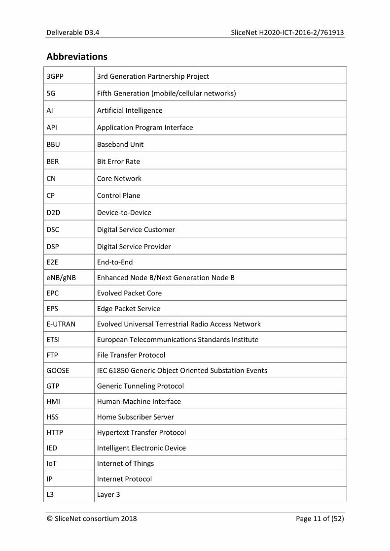
Abbreviations
3GPP 3rd Generation Partnership Project
5G Fifth Generation (mobile/cellular networks)
AI Artificial Intelligence
API Application Program Interface
BBU Baseband Unit
BER Bit Error Rate
CN Core Network
CP Control Plane
D2D Device-to-Device
DSC Digital Service Customer
DSP Digital Service Provider
E2E End-to-End
eNB/gNB Enhanced Node B/Next Generation Node B
EPC Evolved Packet Core
EPS Edge Packet Service
E-UTRAN Evolved Universal Terrestrial Radio Access Network
ETSI European Telecommunications Standards Institute
FTP File Transfer Protocol
GOOSE IEC 61850 Generic Object Oriented Substation Events
GTP Generic Tunneling Protocol
HMI Human-Machine Interface
HSS Home Subscriber Server
HTTP Hypertext Transfer Protocol
IED Intelligent Electronic Device
IoT Internet of Things
IP Internet Protocol
L3 Layer 3
SliceNet H2020-ICT-2014-2/761913 Deliverable D3.4
Page 12 of (52) © SliceNet consortium 2018
LTE Long Term Evolution
MEC Multi-Access Edge Computing
ML Machine Learning
MME Mobility Management Entity
MMS IEC 61850 Manufacturing Message Specification
MTC Machine-Type Communication
NAS National Ambulance Service
NFV Network Function Virtualization
NGMN Next Generation Mobile Networks
NS Network Slice
NSaaS Network Slices as a Service
NSI Network Slice Instance
NSP Network Service Provider
NSSI Network Slice Subnet Instance
NST Network Slice Template
OAI OpenAirInterface
OVS Open vSwitch
P2P Point to Point
PDN Packet Data Network
P-GW PDN Gateway
PMU Phasor Measurement Unit
PNF Physical Network Function
QoE Quality of Experience
QoS Quality of Service
RAN Radio Access Network
R-GOOSE IEC 61850 Routable-Generic Object Oriented Substation Events
RNIS Radio Network Information Service
RRH Remote Radio Head
RRM Radio Resource Management

Deliverable D3.4 SliceNet H2020-ICT-2016-2/761913
© SliceNet consortium 2018 Page 13 of (52)
R-SV IEC 61850 Routable-Sampled Values
RTP Real-time Transport Protocol
SAE System Architecture Evolution
SCADA Supervisory Control And Data Acquisition
SCP Secure Copy
SDK Software Development Kit
SDN Software-Defined Networking
S-GW Serving Gateway
SLA Service-Level Agreement
SST Service Slice Type
TCP Transmission Control Protocol
UDP User Datagram Protocol
UE User Equipment
UP User Plane
UPF User Plane Function
UTSS Unassisted Tele-Stroke Severity Scale
vHSS Virtual Home Subscriber Server
VIM Virtual Infrastructure Management
vMME virtual MME
VNF Virtual Network Function
VNF-FG VNF Forwarding Graph
VNFM Virtual Network Function Management
WAN Wide Area Network

SliceNet H2020-ICT-2014-2/761913 Deliverable D3.4
Page 14 of (52) © SliceNet consortium 2018
1 Introduction
This document specifies the execution, design and implementation principles that are necessary for validating a prototype demonstration of the multi-domain slicing-friendly integrated SliceNet testbed. The aim of the demonstration is, first, to highlight the advantages of the integrated system prototype and, second, to validate its applicability and effectiveness for enabling E2E network slices.
In addition, this document serves as a feasibility study for Network segment integration and interoperability in multi-domain setups for the eHealth and Smart Grid use-cases, as well as in a single domain setup for the Smart City use-case, in response to the requirements of these use-cases. Upon completing the integrated infrastructure, the fuse-cases can start to be ported to the infrastructure and prototyped within the context of task T7.2.
The task described in this document builds upon the developments of its technical work packages (WP2 and WP3), having two goals. Firstly, it has the goal of analysing and utilizing the capabilities of programmable networks in order to amplify the 5G wireless networking experience and, particularly, to exploit network function virtualization (NFV) and software-defined networking (SDN) techniques in order to support network slicing. Secondly, there is a goal of deploying and demonstrating, the SliceNet extended control and management framework in multi-domain scenarios.
1.1 Document Structure
Section 2 presents as a roadmap for infrastructure deployment, providing a generic outline discussion of a SliceNet virtualized infrastructure based on the OpenAirInterface (OAI) [1], Mosaic-5G FlexRAN, LL-MEC, and JOX platforms [2]. Section 3 summarizes the requirements of all use-cases stressing upon the related Quality of Service (QoS) and Quality of Experience (QoE) aspects, and the service topology per use-case. Sections 4 and 5 provide details on the multi-domain infrastructure proposed for the eHealth and Smart Grid use-cases, followed by a description of the single domain infrastructure designed for the Smart City use-case in Section 6. Finally, Section 7 concludes this document by outlining the main points of contributions in this task.
Deliverable D3.4 SliceNet H2020-ICT-2016-2/761913
© SliceNet consortium 2018 Page 15 of (52)
2 A Generic SliceNet 4G-5G Virtualized Infrastructure
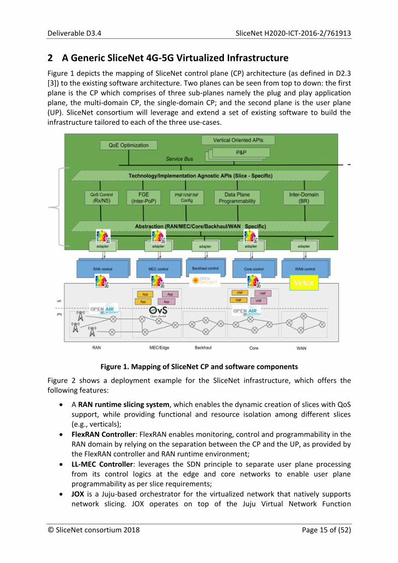
Figure 1 depicts the mapping of SliceNet control plane (CP) architecture (as defined in D2.3 [3]) to the existing software architecture. Two planes can be seen from top to down: the first plane is the CP which comprises of three sub-planes namely the plug and play application plane, the multi-domain CP, the single-domain CP; and the second plane is the user plane (UP). SliceNet consortium will leverage and extend a set of existing software to build the infrastructure tailored to each of the three use-cases.
Figure 1. Mapping of SliceNet CP and software components
Figure 2 shows a deployment example for the SliceNet infrastructure, which offers the following features:
A RAN runtime slicing system, which enables the dynamic creation of slices with QoS support, while providing functional and resource isolation among different slices (e.g., verticals);
FlexRAN Controller: FlexRAN enables monitoring, control and programmability in the RAN domain by relying on the separation between the CP and the UP, as provided by the FlexRAN controller and RAN runtime environment;
LL-MEC Controller: leverages the SDN principle to separate user plane processing from its control logics at the edge and core networks to enable user plane programmability as per slice requirements;
JOX is a Juju-based orchestrator for the virtualized network that natively supports network slicing. JOX operates on top of the Juju Virtual Network Function

SliceNet H2020-ICT-2014-2/761913 Deliverable D3.4
Page 16 of (52) © SliceNet consortium 2018
Management (VNFM) with a plugin architecture that provides an interface to FlexRAN, LL-MEC and the Virtual Infrastructure Management (VIM);
Store is in the form of a distribution repository that contains a constellation of platform packages, Software Development Kits (SDKs), control applications, datasets and models;
OAI-RAN and OAI-CN: provide the 5G communication systems with dedicated core networks support, enabled by 3GPP S1-Flex interface, on per slice basis enabling isolation among different slices;
Inter-domain peering based on OpenDaylight [4] layer 3 (L3) routing capabilities controlled by VELOX [5] to install any connectivity policies required to maintain multi-domain slices.
Figure 2. Deployment example of a single domain SliceNet slicing-friendly infrastructure
In the following, we briefly present the instantiations of platforms for three use-cases namely eHealth, Smart Grid and Smart City.
2.1 Instantiation of Platforms for eHealth
In general, eHealth requires ultra-high data rates and low-latency communication, along with a reliable broadband access to transfer real-time ultra-high-definition video from a connected moving ambulance on its way towards some given geographic destination with hard QoS/QoE support, e.g. the diagnostic team awaiting at some destination hospital. In SliceNet, coordinated RAN and CN programmability is provided by FlexRAN and LL-MEC, allowing reserving the required resources across different domains to sustain the low latency while retaining the required level of reliability for the interactive (time-critical) video traffic and potentially actuation. To trigger healthcare application, the eHealth service is supported by Store that provides application program interfaces (APIs) for service-specific data handling.

Deliverable D3.4 SliceNet H2020-ICT-2016-2/761913
© SliceNet consortium 2018 Page 17 of (52)
2.1.1 Topology and Relationship between LL-MEC, FlexRAN and eNB/gNB
In the eHealth use-case, a subset of eNBs/gNBs must be reconfigured and/or reprogrammed in real-time following the mobility of the ambulance, the paramedics team or the remote doctor(s), in order to guarantee the desired level of QoS/QoE. This requires a close proximity of the controller with respect to the eNBs/gNBs. Indicatively, a region of 10 to 50 eNBs/gNBs could be covered by the same controller to reduce the control channel latency. The user plane is programmed by LL-MEC through User Plane Function (UPF) APIs leveraging OpenFlow messages. Figure 3 shows a generic schematic of network deployment for the eHealth use-case.
2.1.2 Required Network Control Applications
Radio Resource Management (RRM), re-routing, traffic forwarding, caching, content optimization (e.g., in terms of adapting video streaming rate to spatio-temporal radio link variability), event monitoring.
Figure 3. Deployment example of a single domain SliceNet infrastructure for eHealth use-case
2.2 Instantiation of Platforms for Smart Grid
The Smart Grid use-case requires high availability, reliability and a very low-latency communication capability from the infrastructure that is typically provided by the dedicated communication network managed by the vertical. With the ability to provide functional and resource isolation at the level of the RAN together with dedicated CNs, isolation of the different slices from one another can be maintained. The SliceNet infrastructure enables the potential of using public 5G mobile networks to provide critical data communication for Smart Grids. Figure 4 shows a generic schematic of network deployment for the Smart Grid use-case.
SliceNet H2020-ICT-2014-2/761913 Deliverable D3.4
Page 18 of (52) © SliceNet consortium 2018
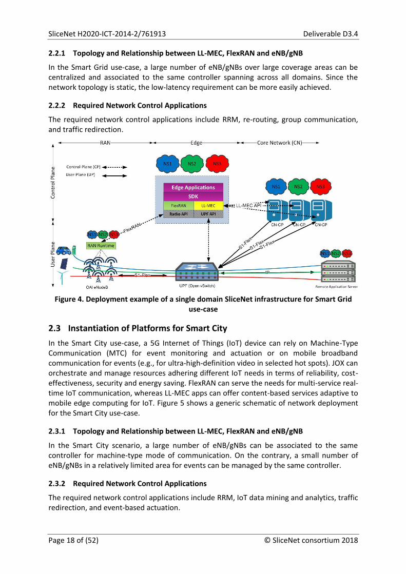
2.2.1 Topology and Relationship between LL-MEC, FlexRAN and eNB/gNB
In the Smart Grid use-case, a large number of eNB/gNBs over large coverage areas can be centralized and associated to the same controller spanning across all domains. Since the network topology is static, the low-latency requirement can be more easily achieved.
2.2.2 Required Network Control Applications
The required network control applications include RRM, re-routing, group communication, and traffic redirection.
Figure 4. Deployment example of a single domain SliceNet infrastructure for Smart Grid use-case
2.3 Instantiation of Platforms for Smart City
In the Smart City use-case, a 5G Internet of Things (IoT) device can rely on Machine-Type Communication (MTC) for event monitoring and actuation or on mobile broadband communication for events (e.g., for ultra-high-definition video in selected hot spots). JOX can orchestrate and manage resources adhering different IoT needs in terms of reliability, cost-effectiveness, security and energy saving. FlexRAN can serve the needs for multi-service real-time IoT communication, whereas LL-MEC apps can offer content-based services adaptive to mobile edge computing for IoT. Figure 5 shows a generic schematic of network deployment for the Smart City use-case.
2.3.1 Topology and Relationship between LL-MEC, FlexRAN and eNB/gNB
In the Smart City scenario, a large number of eNB/gNBs can be associated to the same controller for machine-type mode of communication. On the contrary, a small number of eNB/gNBs in a relatively limited area for events can be managed by the same controller.
2.3.2 Required Network Control Applications
The required network control applications include RRM, IoT data mining and analytics, traffic redirection, and event-based actuation.

Deliverable D3.4 SliceNet H2020-ICT-2016-2/761913
© SliceNet consortium 2018 Page 19 of (52)
Figure 5. Deployment example of a single domain SliceNet infrastructure for Smart City use-case
2.4 Infrastructure Deployment Recommendations
What follows is a recommended workflow of steps for deploying an infrastructure that is specific to use-cases. This workflow ensures a seamless and incremental testbed setup and will be adapted and extended based on service and infrastructure requirements:
Phase 1: Reproduce an in-lab testbed with two personal computers (PCs) as follows, and then connect phones and experiment with the FlexRAN APIs to create multiple RAN slices:
o PC1: OAI-RAN + SDR platform1 o PC2: OAI-CN (with GTP2 in kernel) + FlexRAN
Phase 2: Reproduce an essential in-lab testbed with at least four PCs, as follows. Then, connect phones and experiment with network control apps on top of the FlexRAN and LL-MEC SDKs. Finally, reuse/extend the existing apps to create multi-domain RAN and CN slices:
o PC [1,n]: OAI-RAN + SDR o PC n+1: FlexRAN + LL-MEC + dedicated OAI-CN (using S1-Flex) o PC n+2: OVS3- GTP o PC n+3: SDK + control apps
Phase 3: Deploy an OpenDaylight instance + OvS per simulated autonomous system and configure L3 routing to simulate the peering point between them;
Phase 4: Use JOX and/or Juju [6] to orchestrate the E2E service topology per simulated autonomous system;
Phase 5: Setup the use-case specific infrastructure and deploy the platforms.
1 Software-defined radio (SDR) 2 Generic Tunneling Protocol (GTP) 3 Open vSwitch (OvS)

SliceNet H2020-ICT-2014-2/761913 Deliverable D3.4
Page 20 of (52) © SliceNet consortium 2018
3 Use-case Requirements
3.1 Overview of Infrastructure Requirements per Use-case
Table 1 outlines the infrastructure requirements for each use-case. In the consequent sections, we discuss in further detail the latter requirements along with QoS (and related QoE) aspects per use-case, as well as about the virtual network function (VNF) and service chains, and the implied slicing requirements per use-case.
Table 1. Overview of infrastructure requirements per use-case
Use-case
Infrastructure Requirements
eHealth Dell testbed hardware: Dell R640/R730xd servers, Dell S4148F-ON switches, LimeSDR, Precision 5000 Workstations, Edge Gateway 3000 series
Dell testbed software: OpenStack [7], Open Source MANO (OSM) [8], Juju, OpenDaylight, OAI, LL-MEC, FlexRAN
CIT VNF hardware: Intel RealSense Depth Camera D435 for data capture; Gateway to which camera is attached - needs USB 3.0; CPU and GPU for the MEC; end-user target device (e.g. tablet)
CIT VNF software: Telestroke Assessment MEC-based VNF; Intel RealSense SDK 2.0
RedZinc VNF hardware: Blue-Eye Pack, Hospital client Desktop/Laptop
RedZinc VNF software: Blue-Eye Signaling VNF, Blue-Eye Multi-Party VNF
2 RANs (roaming scenario requirements)
Smart Grid
x Efacec Protection & Control Intelligent Electronic Devices (IEDs)
x LTE Modems
Efacec SCADA/HMI server/station controller/gateway/data concentrator software (UC500)
Efacec engineering software (Automation Studio)
2 RANs (Remote Radio Head - RRH, Base Band Unit - BBU and Evolved Packet Core - EPC)
ALB Network Infrastructure o 2 Servers with the following characteristics:
2 x Intel Xeon Gold 5118 128 GB RAM 2 x HDD 2 TB 7200RPM 6 x Network Interfaces (2 x 10 GB + 4 x 1 GB)
o 2 SDN switches (Pica8)
ALB Virtualized Infrastructure: o 100 vCPU o 64 GB RAM o 10 TB Storage
ALB AI Infrastructure:

Deliverable D3.4 SliceNet H2020-ICT-2016-2/761913
© SliceNet consortium 2018 Page 21 of (52)
o 2 x Intel Xeon Gold 5118 o 128 GB RAM o 12 x 2TB 7.2K RPM Near-Line SAS 6Gbps 3.5in Hot-plug Hard Drive o 2 x 300GB 10K RPM SAS 6Gbps 2.5in Flex Bay Hard Drive o 1 x NVIDIA® Tesla™ P100 GPU Computing Accelerator - 16GB HBM2
- PCIe 3.0 x16
Smart City
HP testbed servers: 3 x DL8 control, management and compute functions, and 1 x DL9, acting as compute node
2xNX-OS switches
Lighting Poles and sensors
IoT gateway (connector)
TestBed Software: OpenStack, OSM, Juju, OAI (RAN + CN), Enterprise Apps (ThingsBoards)
Testbed SDR USRPx310, eNB/gNB (commercial)
Software module for QoE and QoS
3.2 QoS/QoE
Depending on the different services in SliceNet use-cases defined in D2.1 [9], the QoE/QoS in these use-cases focus on either human-to-machine communications (eHealth) or machine-to-machine communications (Smart Grid and Smart City). From the QoE’s perspective, the use-cases are concerned with the application-level quality in relation to the Service Level Agreements (SLAs), e.g., the perceived video-based communication quality in eHealth, and the quality of information communicated in Smart Grid and Smart City, respectively.
3.2.1 eHealth
A recent Prehospital Stroke Study4 developed a system model that included the following QoE functions:
Safety of all present in the ambulance during emergency transportation;
Guaranteed data security to assure patient privacy;
Compliance with all legal and regulatory aspects of emergency care;
Scalability of the system to any type of ambulance at low cost and based on the ‘plug-and-play’ principle to facilitate widespread implementation;
No interference with the regular workflow or standing operating procedures of the ambulance personnel;
Live transfer of key vital parameters;
Robustness and reliability of the technology;
Capability for the tele-consultant to observe the patient from head-to-toe with adequate resolution for evaluation of the patient’s eyes and facial expressions while fixated on a stretcher in a moving ambulance;
User-friendliness and rapid system start-up;
4 Espinoza, A., et al. Development and Pilot Testing of 24/7 In-Ambulance Telemedicine for Acute
Stroke: Prehospital Stroke Study at the Universitair Ziekenhuis Brussel-Project (2016)

SliceNet H2020-ICT-2014-2/761913 Deliverable D3.4
Page 22 of (52) © SliceNet consortium 2018
Integration with the in-hospital acute stroke care process through advanced notification of the in-hospital team and rapid report generation and communication;
Live bidirectional audio and visual communication, with special attention for the functionality that allows the patient to see the tele-consultant while lying in a natural position;
Acceptance by expert teleconsultants and their employers based on seamless integration into their daily practice and respect for a healthy work-life balance (i.e. avoid being confined 24/7 to a stationary workstation but establish a mobile solution based on laptop computers and wireless connectivity).
Within the eHealth use-case, the real-time video streaming service provides a set of requirement ranges for QoS that guarantee an acceptable QoE, from the perspective of the health professionals, as listed in Table 2.
Table 2. Primary QoS requirements in eHealth
QoS measured QoS range
Bandwidth 1-10 Mbps
Latency 30-100 ms
Random Packet Loss ≤ 0.05%
The bandwidth and latency requirements can be mapped to a 2D scatter plot, as shown in Figure 6.
Figure 6. 2D scatter plot for bandwidth and latency
In Figure 6, three regions are identified: (a) This is the unacceptable region. This NSP knows that if the QoS falls within this area the QoE will be poor. There may be a penalty defined in the SLA for operating in this region. (b) This is the optimal QoS region. The customer will generally be happy with the QoE if the provided QoS falls within this area. (c) The customer will be happy because he is getting better service than the one requested, but the involved providers may be operating sub-optimally e.g., if they are allocating more resources than those required. It is an operational decision of the provider in which region the customer service should execute.
From the perspective of the providers, the ideal operation point could be at the lower right corner of region where the bandwidth usage for this customer is minimized (b). However, it

Deliverable D3.4 SliceNet H2020-ICT-2016-2/761913
© SliceNet consortium 2018 Page 23 of (52)
can be expected that some safety margins must be added to accommodate measurement uncertainties, etc. Therefore the QoE optimizer Optimizer defined in D2.3 [3] may aim to (probabilistically) maintain a suitable “operation point” that is well within region (b), subject to some global optimization policy/strategy. By exploiting the options in this solution space through the application of cognition approaches, the eHealth use-case poses an interesting challenge. The concept can be extended to multiple dimensions (e.g., to include other QoS parameters, such as loss, jitter, etc.).
Additionally the customer may extend the SLAs to provide an incentive for the infrastructure providers to maintain the operation point within a specific region. For instance, the customer may offer to pay 10% extra for data volumes that saw a QoS that was within region (b1) and pay 10% less if the service was within region (b2), as shown in Figure 7.
Figure 7. 2D scatter plot for bandwidth and latency (finer granularity for Region b)
Ideally, the above QoS margins can be adapted/updated by the Digital Service Provider (DSP) to better correspond to the actual perceived QoE at some points in time. One simple option to collect such feedback would be to include a simple “5 star/smiley rating” to be clicked by the use-case users at the end of the video stream.
At the end SliceNet may provide an API that the vertical can use to rate the quality of the service, either using an automated mechanism based on some metric derived by the user equipment (UE) application (e.g. observed E2E latency), or manually by collecting feedback from end users utilizing the vertical’s applications (e.g. star rating by doctors). From a SliceNet perspective, the main challenge is to map QoE to QoS, by ensuring that QoS measurements observed by the vertical services match the QoS configured within the slice architecture as well as by mapping the provided QoE feedback to the conditions and configuration of underlying physical resources.
3.2.2 Smart Grid
The Smart Grid use-case involves different types of communications with distinct performance requirements and different degrees of criticality. The use-case relies on IEC 61850 protocols both for time-critical Device-to-Device (D2D) communications and for communication between the SCADA servers and the field devices (i.e., IEDs).
Time-critical D2D communications:
IEC 61850 R-GOOSE o UDP/IP multicast;

SliceNet H2020-ICT-2014-2/761913 Deliverable D3.4
Page 24 of (52) © SliceNet consortium 2018
o Priority traffic; o Continuous heartbeat with faster retransmission when values change; o Configurable heartbeat intervals (typical: 500 ms to 2 s).
IEC 61850 R-SV o UDP/IP multicast; o Priority traffic; o Continuous stream; o Frames sent every ¼ power network cycle (5 ms at 50 Hz).
Non-time-critical communications:
IEC 61850 MMS o TCP/IP; o Client-server;
Other TCP/IP communications o Telnet-like connection using proprietary protocol; o File transfer using FTP and SCP; o Access to HTTP web server; o Other.
The use-case scenarios defined in Deliverable D2.1 [9] cover two distinct Smart Grid self-healing applications that have different requirements. The requirements for each application are enumerated in the subsequent subsections.
Bandwidth requirements for peer-to-peer communications may vary with the number of IEDs integrating a self-healing scheme. The remaining requirements are constant, regardless of the number of IEDs.
The bandwidth values indicated for R-GOOSE communications are not required for continuous streaming – they may be required for short periods of time (tens of milliseconds) during sporadic data bursts. This bandwidth can be shared with lower priority network traffic. These values refer to each IED’s throughput.
3.2.2.1 Application 1: protection coordination + automatic reconfiguration (scenarios 1 and 2)
This application relies on time-critical R-GOOSE for D2D communications, and the QoS requirements are summarised in Table 3.
Table 3. Summary of communication requirements for application 1
Requirements R-GOOSE Non-time-critical File transfer
E2E latency ≤ 10 ms ≤ 300 ms ≤ 10 s
BER < 10-4 < 10-6 < 10-6
Bandwidth 18 Mbps 10 kbps 1 Mbps
Uptime/availability ≥ 99.999 %

Deliverable D3.4 SliceNet H2020-ICT-2016-2/761913
© SliceNet consortium 2018 Page 25 of (52)
3.2.2.2 Application 2: PMU-based differential protection + automatic reconfiguration (scenarios 2 and 3)
This application relies on time-critical R-SV and R-GOOSE for D2D communications, with QoS requirements listed in Table 4.
Table 4. Summary of communication requirements for application 2
Requirements R-GOOSE R-SV Non-time-critical File transfer
E2E latency ≤ 10 ms ≤ 5 ms ≤ 300 ms ≤ 10 s
BER < 10-4 < 10-6 < 10-6 < 10-6
Bandwidth 18 Mbps 2 Mbps 10 kbps 1 Mbps
Uptime/availability ≥ 99.999 %
3.2.3 Smart City
In the Smart City use-case developed and integrated, it is about the entire solution of smart lighting within a city. A Smart City use-case is comprehensive because it includes also smart metering solutions, remote control of city buildings and infrastructure (as temperature, level of quality of air, humidity, noise and so on), traffic control and monitoring, public safety and emergency solutions.
Figure 8. Smart City high-level slicing approach
This city and buildings smart lighting management solution is a 5G network slice use-case, in the slice category of massive machine type communication (mMTC). As key requirements of this use-case, a client that requests to deploy this kind of slice must consider the parameters and limitations of the slice template.
Therefore, the template of slice begins with network topology that is a P2P (Point to Point) communication between the Lighting Management Server and each lighting pole, in a unicast manner, with thousands of endpoints connected. Regarding mobility, since the

SliceNet H2020-ICT-2014-2/761913 Deliverable D3.4
Page 26 of (52) © SliceNet consortium 2018
network topology is static and the lighting poles are fixed, as in this use-case mobility is not present, and thus it is not necessary to have handover control, leading to the consideration that in this case the resources of the Mobility Management Entity (MME) can be reduced. Figure 8 depicts the high-level network slicing approach in the Smart City use-case.
The Smart City use-case has some general network performance requirements, QoS needs that will provide the QoE for the lighting application, as explicitly defined in D2.4 [10]:
Bandwidth – 50 kbps guaranteed for every endpoint (UL & DL). In the case of an incident detected by the network sensors, the slice must be capable to raise the level of bandwidth and resources such that all affected endpoints can be authenticated in the network and have the communication up and running.
Latency – the average of this parameter should be around 500 ms with peaks at a maximum of 1000 ms, between the Management Server and the lighting poles.
Jitter – a mean value of 100 ms and maximum peak at 300 ms, with the comment that in this use-case the jitter value is not an important metric component.
Packet loss – per user flow packet loss should be less than 1% from the total number of packets exchanged per lighting pole, such that monitoring and control of entire slice to be at an optimum level avoiding critical situations.
The network needs for the use-case implementation are not intensive, although they must be taken into consideration for a real scenario implementation case with tens or even hundreds of thousands of lighting devices in place, as a large number of simultaneously connected devices, connection initiated by the device.
Regarding the QoS/QoE approach for the Smart City smart lighting use-case, there are some required sensors and monitoring capabilities that will provide information input for QoS/QoE assurance:
Monitoring capabilities o Service monitoring (E2E monitoring, app level) o Slice monitoring (data specific to a slice) o Traffic monitoring o Topology monitoring (referred as E2E topology) o VNF & Physical Network Function (PNF) monitoring; ping to specific VNFs;
health status; CPU monitoring; interface bandwidth (compared with template)
o QoS metrics and Resources metrics (P&P implementation)
Sensing capabilities o QoE sensors for the service o Defined list of sensors for the Smart City use-case, as each sensor extract one
of the monitored parameter o Defined list of actuators for the Smart City use-case o Proactive fault management, prediction and performance, linked to the first
point
Monitored parameters and values o Bandwidth o Delay o Jitter
Deliverable D3.4 SliceNet H2020-ICT-2016-2/761913
© SliceNet consortium 2018 Page 27 of (52)
o Packet loss, for e2e segment scenario(Lighting Management Server to lighting Poles)
o VMs machine states (CPU, RAM, Networking)
The vertical application has QoE requirements that are directly mapped to network QoS that guarantees the SLA and the KPIs for the apps (monitored parameters and monitoring capabilities), so it may be decided if the QoE for the application is met. The cognitive module aggregates the metrics for the fault management and performance management, the One-Stop API may allow the vertical to provide QoE feedback and the P&P Control to push to the control plane specific configuration information. The Cognition, Artificial intelligence (AI) and Machine Learning (ML) techniques are used for the slice resource management, including optimization, resource allocation, and NFV deployments.
The actuation process is intended to maintain the QoS/QoE levels, by using the QoE sensors (software that filters and interpret the QoS metrics) and is defined by the actuation capabilities:
actuation will be performed to bring QoS indicators to desired levels;
actuations on the network slices to avoid the predicted faults (prediction);
scaling of virtual infrastructure;
QoE enabled on-demand sensing.
As an example, the Smart City use-case implementation can be based on the “slicing template” specifications as mentioned in Annex A.
3.3 Service topology
3.3.1 eHealth
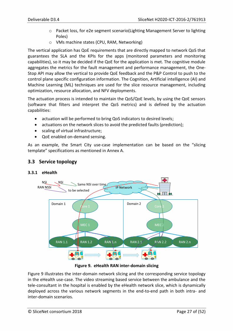
Figure 9. eHealth RAN inter-domain slicing
Figure 9 illustrates the inter-domain network slicing and the corresponding service topology in the eHealth use-case. The video streaming based service between the ambulance and the tele-consultant in the hospital is enabled by the eHealth network slice, which is dynamically deployed across the various network segments in the end-to-end path in both intra- and inter-domain scenarios.
SliceNet H2020-ICT-2014-2/761913 Deliverable D3.4
Page 28 of (52) © SliceNet consortium 2018
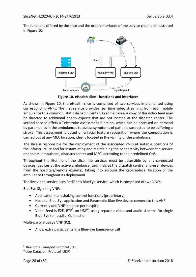
The functions offered by the slice and the order/interfaces of the service chain are illustrated in Figure 10.
Figure 10. eHealth slice - functions and interfaces
As shown in Figure 10, the eHealth slice is comprised of two services implemented using corresponding VNFs. The first service provides real time video streaming from each mobile ambulance to a common, static dispatch center. In some cases, a copy of the video feed may be directed to additional health experts that are not located at the dispatch center. The second service offers a Telestroke Assessment function, which can be accessed on demand by paramedics in the ambulances to assess symptoms of patients suspected to be suffering a stroke. This assessment is based on a facial feature recognition where the computation is carried out at any MEC location, ideally located in the vicinity of the ambulance.
The slice is responsible for the deployment of the associated VNFs at suitable positions of the infrastructure and for instantiating and maintaining the connectivity between the service endpoints (ambulance, dispatch center and MEC) according to the predefined QoS.
Throughout the lifetime of the slice, the services must be accessible by any connected devices (devices at the active ambulance, terminals at the dispatch centre, end-user devices from the hospitals/remote experts), taking into account the geographical location of the ambulance throughout its deployment.
The live video service uses RedZinc’s BlueEye service, which is comprised of two VNFs:
BlueEye Signaling VNF:
Application handshaking control functions (proprietary)
Hospital Blue-Eye application and Paramedic Blue-Eye device connect to this VNF
Currently one VNF instance per hospital
Video feed is E2E, RTP5 on UDP6, using separate video and audio streams for single Blue-Eye to hospital Connection
Multi-party BlueEye VNF (RZ):
Allow extra participants in a Blue-Eye Emergency call
5 Real-time Transport Protocol (RTP)
6 User Datagram Protocol (UDP)

Deliverable D3.4 SliceNet H2020-ICT-2016-2/761913
© SliceNet consortium 2018 Page 29 of (52)
Splits video/audio amongst participants via WebRTC, enabling more doctors to help diagnose a situation on the field, including mobile doctors such as moving in a car to the event site.
CIT’s Telestroke Assessment service is implemented as a single VNF running at the MEC infrastructure
Telestroke Assessment VNF (CIT)
3.3.2 Smart Grid
3.3.2.1 Use-case High-Level Roles & Relationships
The Smart Grid use-case relies on ultra-low latency communications between the power grid sensors/actuators (IEDs). Additionally, it also requires high density of network communications coverage, as well as with high quality (in terms of ultra-low latency capacity). Based on these requirements, the most critical aspect of the use-case is the RAN coverage. Since it is very difficult for a single Network Service Provider (NSP A) to be able to cover the whole country geography with the desired service-level agreement (SLA) for the use-case, a second NSP (B) is involved to provide complimentary RAN connectivity. Figure 11 presents the high-level overview of the use-case deployment.
Figure 11. Use-case high-level overview
In addition to providing RAN, NSP A also provides an EPC and a Core service. Both, NSP A and NSP B implement Network Slices (NSs) on their environment/network, and expose these Network Slices as a Service (NSaaS) to be subscribed by other entities. In this case, a DSP is responsible for subscribing for the NSP A and NSP B NSaaS offers and creating/composing an end-to-end Ultra-low Latency Service for the Vertical. This will allow the Vertical to attach their IEDs to the RANs and guarantee always-on connectivity with very low latencies among them.
Shortly, in terms of roles and relationships, the following responsibilities are expected:
Network Service Provider A (NSP A) o Network Slices (NSs)

SliceNet H2020-ICT-2014-2/761913 Deliverable D3.4
Page 30 of (52) © SliceNet consortium 2018
RAN Network Slice EPC Network Slice Core Network Slice
o Network Slices as a Service (NSaaS) RAN Network Slice as a Service EPC Network Slice as a Service Core Network Slice as a Service
Network Service Provider B (NSP B) o Network Slices (NSs)
RAN Network Slice o Network Slices as a Service (NSaaS)
RAN Network Slice as a Service
Digital Service Provider (DSP) o Ultra-low Latency Digital Service
3.3.2.2 Use-case High-Level Overview
This section provides a high-level overview of the use-case’s main phases.
3.3.2.2.1 Power Grid and Communications Network Up & Running
Figure 12. Power Grid and communications network up & running
Initially, the power grid is up and running, as shown in Figure 12. The following IEDs are deployed:
IEDs o 5 Active (closed) IEDs distributed in the power grid; o 1 Passive (open) IED.
IEDs are connected to the RANs from NSP A and NSP B and are communicating with each using the ultra-low latency digital service.

Deliverable D3.4 SliceNet H2020-ICT-2016-2/761913
© SliceNet consortium 2018 Page 31 of (52)
3.3.2.2.2 Fault Detection & Protection Coordination Activated
Subsequently, a fault occurs in section c, as illustrated in Figure 13. The IEDs upstream from the fault (IED1, IED2, and IED3) sense the fault and open the corresponding circuit breaker unless this operation is blocked. Since the IED1 operation is blocked by IED2 and IED3, and the IED2 operation is blocked by IED3, IED3 will be the only one opening the circuit breaker.
After opening the circuit breaker, all further power grid sections will be de-energized - sections c (faulty section) and d (healthy section) will have no electrical power.
Figure 13. Fault (short-circuit) in section c.
3.3.2.2.3 Automatic Reconfiguration
Figure 14. Open the circuit breaker controlled by IED4 in order to isolate faulty section c.

SliceNet H2020-ICT-2014-2/761913 Deliverable D3.4
Page 32 of (52) © SliceNet consortium 2018
In this phase shown in Figure 14, IED3 detects the fault, measuring short-circuit current levels, and starts its protection functions. This device that cleared the fault (IED1) sends an open command to the nearest downstream device (IED4) via IEC 61850 GOOSE.
After the device IED4 opens, a close command is sent to the IED connected to the normally open point (IED5) via IEC 61850 GOOSE, as highlighted in Figure 15.
Figure 15. Close the circuit breaker controlled by IED5 in order to restore power to the healthy section d.
3.3.2.2.4 Power Grid Reconfigured
Figure 16. Reconfigured power grid, after a fault has been cleared in section c.

Deliverable D3.4 SliceNet H2020-ICT-2016-2/761913
© SliceNet consortium 2018 Page 33 of (52)
In the final phase as shown in Figure 16, IED5 closes, energizes the d section and all line sections are now supplied and are operating under normal conditions. Power system currents and voltages in these sections are stable and at normal levels. All communications between field IEDs and between IEDs and the control center/ substation are up (all communications must be up – even for IEDs in de-energized sections).
After section c has been repaired, the system will be manually reset to its default configuration (see Figure 12) and normal operation will be resumed.
3.3.3 Smart City
The Smart City use-case is oriented to the vertical’s capabilities to access specific communication services and application, covered by the massive MTC in IoT areas.
The Smart City Smart Lighting application and service instantiation is composed by several components related to the Enterprise apps instantiation as they were specified in deliverable D3.3 [11], with element components support from D3.2 [12] related to RAN and Core.
The platform instantiation requires the using of the next components:
Lighting poles including smart sensors with different radio types capabilities o Traditional LoRa and 4G RAN in an early stage (part of Enterprise Segment) o Transition to OAI interface, to fully benefits and demonstrate the “slicing”
capabilities
IoT gateway, acting as a secured connector with specific characteristic, with functions and capabilities that are described in D3.2 [12], considered in the instantiation process as a fix and static gateway.
SliceNet Core, with two approaches o Traditional EPC, that connects traditional RAT to the SliceNet IoT Enterprise
Segment, validating the enterprise prototype [11] o Core segment, vEPC implementation (OAI RAN + Core), based on [12]
Enterprise Segment, including IoT middleware deployment and instantiation and different apps, as prototyped in [12]
It may be considered in fact that the instantiation of the Smart City platform consists of three main components, as presented in Figure 17, with 5G RAN-Core slicing capabilities, programmable Data and Control Plane as a 5G ready virtualized infrastructure, extended to the Enterprise segment:
RAN (FlexRAN)
Core Network (OAI Core)
Enterprise and applications
Deployment of Smart City use-case for the SliceNet Infrastructure based on the OAI, Mosaic-5G FlexRAN and Enterprise prototyped is represented in access part by ETTUS USRP X310 [13] or by an Huawei commercial eNodeB, for the physical layer of the eNodeB, from the MAC layer upper, it is to instantiate the OAI platform represented on one of the Virtual Machines hosted on Orange servers testbed (HPE ProLiant DL380 Gen9 Server). Another Virtual Machine is hosting the instance for the vEPC which is offering the connection of the eNodeB to the Enterprise Infrastructure where is hosting the Thingboards application.
SliceNet H2020-ICT-2014-2/761913 Deliverable D3.4
Page 34 of (52) © SliceNet consortium 2018
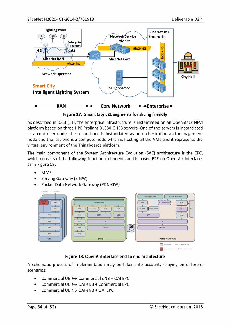
Figure 17. Smart City E2E segments for slicing friendly
As described in D3.3 [11], the enterprise infrastructure is instantiated on an OpenStack NFVI platform based on three HPE Proliant DL380 GHE8 servers. One of the servers is instantiated as a controller node, the second one is instantiated as an orchestration and management node and the last one is a compute node which is hosting all the VMs and it represents the virtual environment of the Thingboards platform.
The main component of the System Architecture Evolution (SAE) architecture is the EPC, which consists of the following functional elements and is based E2E on Open Air Interface, as in Figure 18:
MME
Serving Gateway (S-GW)
Packet Data Network Gateway (PDN-GW)
Figure 18. OpenAirInterface end to end architecture
A schematic process of implementation may be taken into account, relaying on different scenarios:
Commercial UE ↔ Commercial eNB + OAI EPC
Commercial UE ↔ OAI eNB + Commercial EPC
Commercial UE ↔ OAI eNB + OAI EPC
Deliverable D3.4 SliceNet H2020-ICT-2016-2/761913
© SliceNet consortium 2018 Page 35 of (52)
OAI UE ↔ OAI eNB + OAI EPC
OAI UE ↔ OAI eNB + Commercial EPC
OAI UE ↔ Commercial eNB + Commercial EPC
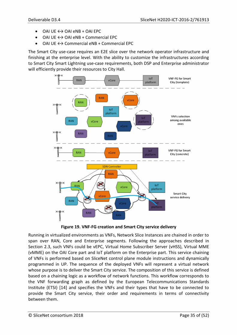
The Smart City use-case requires an E2E slice over the network operator infrastructure and finishing at the enterprise level. With the ability to customize the infrastructures according to Smart City Smart Lightning use-case requirements, both DSP and Enterprise administrator will efficiently provide their resources to City Hall.
Figure 19. VNF-FG creation and Smart City service delivery
Running in virtualized environments as VNFs, Network Slice Instances are chained in order to span over RAN, Core and Enterprise segments. Following the approaches described in Section 2.3, such VNFs could be vEPC, Virtual Home Subscriber Server (vHSS), Virtual MME (vMME) on the OAI Core part and IoT platform on the Enterprise part. This service chaining of VNFs is performed based on SliceNet control plane module instructions and dynamically programmed in UP. The sequence of the deployed VNFs will represent a virtual network whose purpose is to deliver the Smart City service. The composition of this service is defined based on a chaining logic as a workflow of network functions. This workflow corresponds to the VNF forwarding graph as defined by the European Telecommunications Standards Institute (ETSI) [14] and specifies the VNFs and their types that have to be connected to provide the Smart City service, their order and requirements in terms of connectivity between them.
SliceNet H2020-ICT-2014-2/761913 Deliverable D3.4
Page 36 of (52) © SliceNet consortium 2018
Delivery of Smart City service consists in provisioning the paths through the selected chain of VNFs. It accomplishes the use of forwarding functions running on top of NFVI to realize the proper connectivity among VNF instances specified in the VNF-FG. The enforcement of data flow forwarding rules is based on SDN controller capability to program the rules across network nodes. Figure 19 illustrates the VNF-FG creation and service delivery in the Smart City use-case.

Deliverable D3.4 SliceNet H2020-ICT-2016-2/761913
© SliceNet consortium 2018 Page 37 of (52)
4 eHealth Integrated Multi-Domain Slicing-Friendly Infrastructure
4.1 Introduction
In-ambulance telemedicine is a recently developed and promising approach for improving emergency care. The SliceNet eHealth use-case builds on a Pre-hospital Stroke Study7 that aims to facilitate widespread use of in-ambulance telestroke diagnosis and improved patient treatment pathways.
To date, significant progress has been made on in-hospital stroke management, but a scalable pre-hospital solution has not yet been established. Solving this problem would speed up treatment initiation by early activation of the in-hospital stroke response, curtail the risk of misdiagnosis, reduce the proportion of missed opportunities for treatment with intravenous thrombolysis and/or endovascular treatment, and avoid patient admission to inadequate clinical facilities.
Use of a tele-consultant to assist the ambulance personnel to correctly manage the stroke patient’s treatment pathway is desirable. Tele-consultant heuristics are required to efficiently engage in the complex patient–doctor interactions, and to make appropriate medical decisions under time pressure. For these reasons, stroke diagnosis and patient selection by paramedics is not optimal, and real-time intervention by clinical experts is needed.
Research on pre-hospital telemedicine for stroke (tele-stroke) assessment is proving to be acceptable, but reliable and available mobile broadband is acting as a take-up deterrent. 5G network slicing could be the cellular solution required for reliable audio-video communication in moving ambulances.
For every patient with suspicion of acute stroke, a stroke expert is brought virtually into the ambulance to effectively provide the following pre-hospital treatment pathway (Figure 20):
Patient triage,
Pre-hospital notification of the in-hospital team,
Collection of key information (e.g. patient identity and demographics, vital parameters, clinical presentation, medical history, premorbid functional state, concomitant medication),
Assessment of stroke severity,
Identification of candidates for specific stroke treatment (e.g. thrombolytics, endovascular approaches, aggressive blood pressure lowering, neurosurgical interventions), and
To automatically generate and send a report containing all this information to the in-hospital team.
This approach could help improve the delay from stroke onset to initiation of specific stroke therapy.
7 Espinoza, A., et al. Development and Pilot Testing of 24/7 In-Ambulance Telemedicine for Acute Stroke: Prehospital Stroke Study at the Universitair Ziekenhuis Brussel-Project (2016)

SliceNet H2020-ICT-2014-2/761913 Deliverable D3.4
Page 38 of (52) © SliceNet consortium 2018
Figure 20. Visualization of acute stroke care processes under standard medical care (upper line in red) and using in-ambulance telemedicine (bottom line in green)
The eHealth scenario envisions a slice that spans multiple administrative domains as depicted in Figure 21 of the previous section. Each domain takes on the role of an NSP and offers a domain-level slice where an E2E slice is composed of multiple domain-level slices and can be managed by a DSP. The minimal E2E slice is comprised of i)one or more mobile operators, which provide RAN, MEC and Core segments, ii) the Enterprise domain which contains the ambulances, the dispatch center and associated resources, and iii) one or more WAN domains (e.g. ISPs) which interconnect other domains. The multi-domain infrastructure on which the eHealth use-case will be prototyped is depicted below. It consists of two mobile operator domains (NSP1, NSP3), each of which has infrastructure to support RAN, MEC and Core components. Specifically this includes commodity servers with programmable NICs (P4) for hosting the MEC and Core components as well as an extendible RAN segment based on ECOMs 5G Mosaic stack. The Core segment provides a gateway responsible for realizing the connection to external domains. The WAN domain (NSP2) emulates an ISP that uses OpenFlow-enabled switches to implement the mechanisms necessary to configure specific QoS parameters between domains (e.g. classification, queuing disciplines). NSP2 may also potentially hosts VNFs by offering a VIM platform with support for service chaining. The Enterprise domain in NSP4 contains the dispatch center and associated IT infrastructure (workstations, switches) as well as the infrastructure deployed in the ambulance. This includes the BlueEye glasses and modem, as well as an ambulance mounted camera connected to a gateway with a modem. We also assume that the health experts are connected to the Enterprise domain using dedicated resources with the exception of cases that require intervention of a “field hospital”, which will be a health expert dispatched to the site in acute events (patients incarcerated in a car pile-up) where on-site expertise is needed, with the Blue-Eye Multi-Party VNF it is possible for the moving expert to be included in ongoing diagnosis, but even in this case, the presence of the experts in the Enterprise domain is assumed.

Deliverable D3.4 SliceNet H2020-ICT-2016-2/761913
© SliceNet consortium 2018 Page 39 of (52)
Figure 21. Overview of the eHealth integrated multi-domain slicing-friendly infrastructure
What multi-domain slicing requirements/support are/is envisioned
Before the slice deployment, the required VNF components will be provisioned within any domain that can support the resources according to the SLA.
Once an ambulance is deployed, it will connect to the most suitable RAN (in terms of signal strength, QoS capabilities) depending on its geographical location. As the ambulance moves, a handover must take place, which transparently migrates all established flows across RAN domains as necessary. For the tele-stroke scenario the request for remote stroke analysis will be forwarded to the nearest available instance of the facial recognition VNF. To minimize the instantiation time multiple VNF may be pre-provisioned across multiple feasible MEC locations.
4.2 Tele-Stroke Assessment VNF
The time taken to diagnose a stroke is critical to patient outcome. The Tele-Stroke Assessment VNF is a machine learning application based on the Unassisted Tele-Stroke Severity Scale (UTSS) and has been designed to assist with patient diagnosis, whilst still inside the ambulance, and as they are being transported back to the hospital. The application gives the consultant located at the hospital a first indicator of the type of stroke the patient might have, and in this way enable them to make the proper arrangements ahead of patient arrival at hospital. Any time saved with patient diagnosis, whilst still inside the ambulance, is critical here to patient outcome.
The Tele-stroke Assessment VNF, as described in Figure 22, uses an Intel RealSense camera, along with the accompanying SDK, to capture colour and depth images from a patient in an ambulance suspected of suffering from a stroke.

SliceNet H2020-ICT-2014-2/761913 Deliverable D3.4
Page 40 of (52) © SliceNet consortium 2018
Figure 22. High-level architecture for Tele-Stroke Assessment VNF
This application is connected through TCP/IP8 sockets to a cloud program running on the MEC. The MEC application is responsible for sending instructions to the patient and to perform analysis on the image data, which is sent from the ambulance application. The instructions used to conduct the examination are defined in UTSS, which is used to detect possible signs of stroke.
When the initial connection is made between the ambulance and MEC applications, the MEC application sends the first instruction to the patient in the ambulance. The ambulance application then starts transmitting image data of the patient to the MEC. As the MEC receives image data, it performs an analysis using machine learning to detect for possible signs of stroke. This process loops until all the steps are completed. The MEC application can then send the results of the analysis to the hospital / doctor.
4.3 Blue-Eye VNFs
The Blue-Eye system (Figure 23) is designed to provide portable video system to paramedics for remote diagnosis in acute situations, which is delivered via a glasses mounted camera connected to a custom 4G enabled device and battery in the paramedic belt.
8 Transmission Control Protocol (TCP)/Internet Protocol (IP)

Deliverable D3.4 SliceNet H2020-ICT-2016-2/761913
© SliceNet consortium 2018 Page 41 of (52)
Figure 23. Blue-Eye System
In a standard mode of functioning, the system connects to a hospital client, where a medical expert is attending, via a direct point-to-point stream after an authentication done in a VNF (Figure 24). This authentication also provides the appropriate addresses for the clients to find each other.
Figure 24. Blue-Eye System working on single direct stream
For the special cases that require an on-site medical expert, the Blue-Eye also has a Multi-party VNF for WebRTC video conferencing, which allows the moving expert to participate on the remote diagnosis while travelling to the event site (Figure 25).
Figure 25. Blue-Eye System working on multi-party streaming
4.4 Infrastructure Deployment Milestones
During the first phase of the deployment of the SliceNet infrastructure at the DellEMC site in Cork, the eHealth team are taking an incremental deployment approach, which builds complexity into the testbed at each milestone, whilst mitigating complexity risk (see Figure 26):
M01: RZ and CIT VNFs deployed and tested E2E without QoS non-wireless

SliceNet H2020-ICT-2014-2/761913 Deliverable D3.4
Page 42 of (52) © SliceNet consortium 2018
M02: RZ and CIT VNFs deployed and tested E2E without QoS wireless (WiFi and/or 4G)
M03: RZ and CIT VNFs deployed and tested E2E with SliceNet RAN QoS
Figure 26. eHealth infrastructure deployment milestones
The above milestones are targeted for completion during the first six months of the second year of the project, and will set the baseline infrastructure deployment that will be handed over to WP8 for integration of the SliceNet enabling technologies designed in WPs 4-6.

Deliverable D3.4 SliceNet H2020-ICT-2016-2/761913
© SliceNet consortium 2018 Page 43 of (52)
5 Smart Grid Integrated Multi-Domain Slicing-Friendly Infrastructure
The Smart Grid use-case will be implemented in four phases as mentioned in the following subsections.
5.1 Smart Grid Use-case - Phase 1
In the first phase as shown in Figure 27, the demonstrator will integrate a minimal setup of the Smart Grid use-case testbed in the network infrastructure, in which there will be a single “remote” IED connected to the lab-based 5G network communicating to a “substation” PC running the Efacec engineering tool (Automation Studio) and, if viable within the imposed timeframe, a SCADA server software (Efacec UC500). In this phase, we will have only one network domain.
Figure 27. Smart Grid infrastructure (phase 1)
5.2 Smart Grid Use-case - Phase 2
In this second phase as shown in Figure 28, we will have the communication between two IEDs in the Smart Grid use-case testbed. This scenario will give us the validation of the proposed latency requirements for the implemented network, which will be very relevant for the Smart Grid use-case validation.

SliceNet H2020-ICT-2014-2/761913 Deliverable D3.4
Page 44 of (52) © SliceNet consortium 2018
Figure 28. Smart Grid infrastructure (phase 2)
5.3 Smart Grid Use-case - Phase 3 and 4
In the third and fourth phases as shown in Figure 29, the infrastructure will allow us to exercise the Smart Grid use-case in all its possibilities, i.e., communication between IEDs, communication between IEDs-SCADA, communication between IEDs-Automation Studio and the use of a Smart Grid simulator to test the overall infrastructure.
In this final scenario, we will exercise the multi-domain feature, where the IEDs in the domain 2 will communicate with IEDs in the domain 1 via the vEPC of domain 1. The E2E NSI will consist of 2 NSSIs of each of these domains.
Figure 29. Smart Grid infrastructure (phase 3 and 4)
Deliverable D3.4 SliceNet H2020-ICT-2016-2/761913
© SliceNet consortium 2018 Page 45 of (52)
5.4 Infrastructure Deployments Milestones
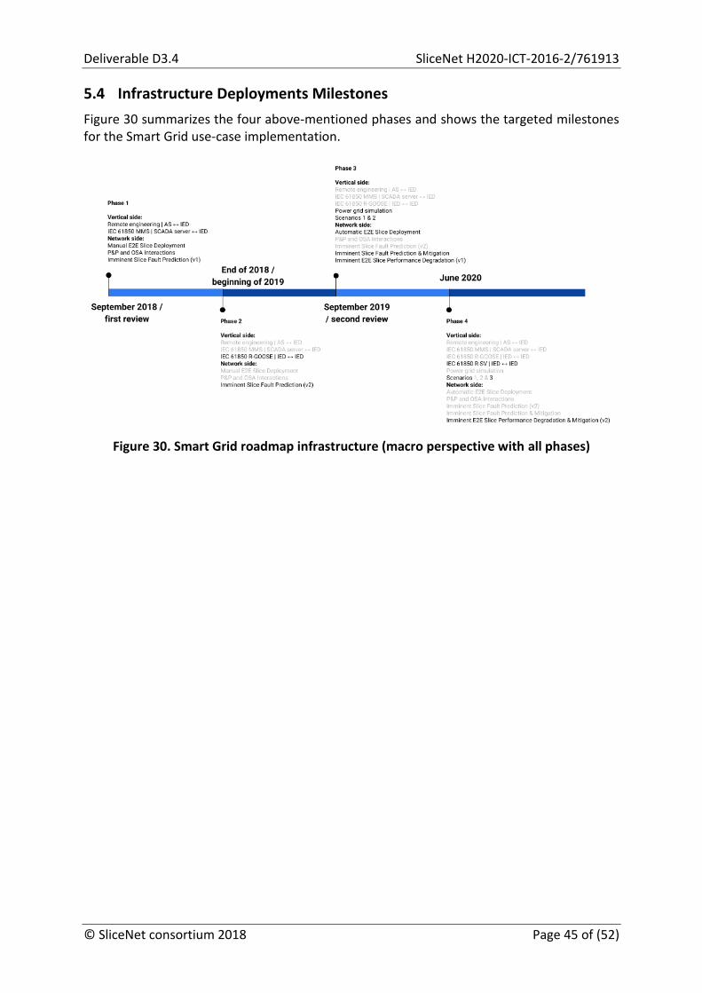
Figure 30 summarizes the four above-mentioned phases and shows the targeted milestones for the Smart Grid use-case implementation.
Figure 30. Smart Grid roadmap infrastructure (macro perspective with all phases)

SliceNet H2020-ICT-2014-2/761913 Deliverable D3.4
Page 46 of (52) © SliceNet consortium 2018
6 Smart City Integrated Multi-Domain Slicing-Friendly Infrastructure
6.1 Introduction
There are several approaches for the multi-domain envision, as expressed by different standardization bodies and detailed in [15] and [10], based on two main views, the Next-Generation Mobile Networks (NGMN) and 3GPP, and focused on several categories and scenarios as they are related to the vertical business cases: Roaming scenario and Business vertical scenario.
Moreover, there are also defined categories of administrative domain and configuration in the context of a 5G architecture framework:
Inter-domain configuration, referring to two different administrative domains required to provide the needed resources for a specific service, including network slice required support;
Multi-domain configuration, referring to more than two different administrative domains required to provide the needed resources for a specific service, including network slice required support.
SliceNet project defines roles that apply to multi-domain scenario and includes responsibilities for each actor:
Digital Service Customer (DSC) - contains the consumers of the digital services;
Digital Service Provider (DSP) - manages and exposes digital services, delivered over multiple NSP;
Network Service Provider (NSP) - exposes the network infrastructure.
The role played by the actors in the Smart City slicing-friendly infrastructure, with respect of the Section 2.4 specifications, combines the two actors roles DSP and NSP into a single one, provided in this particular situation by the telco operator that is interested also in exposing the digital services to the consumers.
The DSP and NSP combined actor fulfils the next requirements:
Network infrastructure;
Network slices;
E2E network slice and services;
Orchestration and management of resources, network slice and services.
As defined, a slicing-friendly infrastructure within a domain is an efficient fast deployment of a specific vertical slice through 5G software-networking concepts, including the defined QoS and QoE aspects. The Smart City slice is a cross-domain infrastructure layer (data layer, control layer and management layer) and has the particularity to be extending to the enterprise domain, which in this approach is under the telco administration, as presented in Figure 31.

Deliverable D3.4 SliceNet H2020-ICT-2016-2/761913
© SliceNet consortium 2018 Page 47 of (52)
Figure 31. Smart Lighting roles and responsibilities
The presented unified role and responsibility for this use-case (single-domain administration) has the particularity that it covers also the Enterprise segment (see Figure 17), as the lighting poles and IoT platform are specific elements of an enterprise, as all the network elements are integrated into the SliceNet architecture for the use-case as presented in Figure 32.
Figure 32. Smart Lighting combined DSP and NSP cross-domain planes
The proposed implementation of the use-case has the advantage to be closer to real-life scenarios (related mainly to the integration of the enterprise developed segment under the telco administration). Another advantage of this implementation is the combined role of a DSP and NSP that allows SliceNet to explore and technical innovate (without business limitations), to introduce the E2E slicing-friendly concepts, a service-based-architecture with relevant elements as cognition, sensors and actuation for QoE and QoS.
The Smart Lighting slicing approach is high level presented into Figure 33, by identifying the key virtualized network elements, service template and slicing information model, SDN/NFV.

SliceNet H2020-ICT-2014-2/761913 Deliverable D3.4
Page 48 of (52) © SliceNet consortium 2018
Figure 33. Smart City integrated infrastructure for network slicing
6.2 Infrastructure Deployments Milestones
A schematic use-case implementation (Figure 34), single-domain approach, is intended to be implementing in the next two environments:
Orange development laboratory o Commercial lighting sensor - traditional eNodeB - traditional (v)EPC -
Enterprise IoT Platform (validate Enterprise) - no QoS/QoE; o Commercial lighting sensor - OAI eNodeB - OAI EPC - Enterprise IoT Platform
(validate E2E slicing friendly & demonstrate business case) - no QoS/QoE; o OAI UE - OAI eNodeB - OAI EPC - Enterprise IoT Platform (E2E slicing creation
and validation) - QoS/QoE;
Partner laboratory9 o OAI UE - OAI eNodeB - OAI EPC - Enterprise IoT Platform (multiple network
slice development environment, multi-domain management, E2E slicing friendly) - QoS/QoE.
9 EURECOM

Deliverable D3.4 SliceNet H2020-ICT-2016-2/761913
© SliceNet consortium 2018 Page 49 of (52)
Figure 34. Smart City infrastructure deployment milestones

SliceNet H2020-ICT-2014-2/761913 Deliverable D3.4
Page 50 of (52) © SliceNet consortium 2018
7 Conclusions
The main objective of this document is to present the activities related to the design and prototyping of integrated multi-domain infrastructure to achieve an end-to-end slicing-friendly infrastructure. The proposed integrated infrastructure, which includes all the concerned network segments ranging from the access to the core network and the backbone segment, leverages OAI and Mosaic-5G platforms to provide customized deployments according to the need of different SliceNet use-cases. In addition, the current document serves as a feasibility study for the network segment integration and interoperability in single/multi-domain setups for the SliceNet use-cases (eHealth, Smart Grid, and Smart City). Finally, the use-cases will be ported to the infrastructure and prototyped within the context of task T7.2.
Deliverable D3.4 SliceNet H2020-ICT-2016-2/761913
© SliceNet consortium 2018 Page 51 of (52)
References
[1] OpenAirInterface, Jul. 2018, [Online]. Available: http://www.openairinterface.org/
[2] Mosaic-5G.io, Jul. 2018, [Online]. Available: http://mosaic-5g.io/
[3] SliceNet, Deliverable 2.3 - Control Plane System Definition, APIs and Interfaces, Apr. 2018
[4] OpenDaylight, Jul. 2018, [Online]. Available: https://www.opendaylight.org/
[5] VELOX, Jul. 2018, [Online]. Available: http://www.redzinc.net/solutions/
[6] Juju, Jul. 2018, [Online]. Available: https://jujucharms.com/
[7] OpenStack, Jul. 2018, [Online]. Available: https://www.openstack.org/
[8] Open Source MANO (OSM), Jul. 2018, [Online]. Available: https://osm.etsi.org/
[9] SliceNet, Deliverable 2.1 - Vertical Sector Requirements Analysis and Use-case, Nov. 2017
[10] SliceNet, Deliverable 2.4 - Management Plane System Definition, APIs and Interfaces, May. 2018
[11] SliceNet, Deliverable 3.3 - Design and Prototyping of 5G-Connected Virtualized Enterprise Infrastructure and Services, Jun. 2018
[12] SliceNet, Deliverable 3.2 - Design and Prototyping of SliceNet Virtualised 5G RAN-Core Infrastructure, May. 2018
[13] ETTUS USRP X310, Jul. 2018, [Online]. Available: https://www.ettus.com/product/details/X310-KIT
[14] ETSI GS NFV 002, Network Function Virtualization; Architectural Framework, Oct. 2013
[15] SliceNet, Deliverable 2.2 - Overall Architecture and Interfaces Definition, Nov. 2017

SliceNet H2020-ICT-2014-2/761913 Deliverable D3.4
Page 52 of (52) © SliceNet consortium 2018
Annex A A Slicing Template for the Smart Grid Use-case
This Annex describes an example of a slicing template for the Smart City use-case. Specifically, this use-case implementation can be based on the “slicing template” specifications, considering the next slice information definitions and links between them:
1. Slice Resource Level 1.1. Network Slice Instance (NSI), realize (1.2), deployed by Network Slice Template (NST) 1.2. Network Slice, described by NST 1.3. Network Service Descriptor, realize by NSS 1.4. VNFs and PNFs, contained by (1.3) 1.5. VNF & PNF Descriptors, realize (1.4) 1.6. Network Functions, realized by (1.5), containing NSS 1.7. Network Service, aggregates NFs
2. Service Slice Resource Level 2.1. Service catalogue 2.2. PNF and VNF involved (specific for use-case) 2.3. Aggregating the network services 2.4. Network functions 2.5. Link to the Network Slice: resource requirements for specific bandwidth, delay,
jitter, packet loss, prioritization; QoS 3. Service Slice level
3.1. Service Slice Type (SST) – mIoT (parameters) 3.2. Network Slice, contained by the SST, described by (3.3) 3.3. Network Slice Template (NST) 3.4. Deployment of the NSI using (3.3)
The QoE architecture, as defined in D2.3 [3] and D2.4 [10], contains the QoE Manager (cognition for QoE metrics) and the QoE Optimizer (cognition for slice policies and monitoring for local decision engine) that based on the Smart City described parameters will ensure the QoS/QoE, implemented through the actuators (as a limited list) that for at E2E Smart City level:
set and modify the Slice Configuration for a specific need: o management of E2E latency within the slice by modifying the NS and NSS
sequence;
set and modify the NS and NSS configuration: o increase bandwidth of a NS; o increase the CPUs;
set specific network values (e.g. bandwidth) established through cognition, based on metrics monitoring;
set sensors for packet loss, delay, jitter through the policy framework and deploy actuation based on thresholds;
set the specific parameters on the SliceNet CP;
set the triggered management procedures through the CP configuration by the P&P (devices planned upgrades);
set and modify slice configuration through prediction and historical information.
[End of document]


![HyRiM...Hybrid Risk Management for Utility Networks Collaborative Project Deliverable 3.4 Monitoring Framework and Reference Architecture Due date of deliverable: [30/09/2016] Actual](https://static.fdocuments.in/doc/165x107/60215cf6efa62f45755ffd56/hyrim-hybrid-risk-management-for-utility-networks-collaborative-project-deliverable.jpg)