Deliverable 2 – Technical Report … · Greg Oakes James Pattison Jack Pittar Ryan Pope Matthew...
22
2016 UAV Challenge Deliverable 2: Technical Report www.canberraUAV.org.au
Transcript of Deliverable 2 – Technical Report … · Greg Oakes James Pattison Jack Pittar Ryan Pope Matthew...

2016 UAV Challenge
Deliverable 2:
Technical Report 2014 UAV Outback Challenge – Search and Rescue Challenge
www.canberraUAV.org.au

Page 2 of 22
1 Table of Contents 1 Table of Contents ....................................................................................................................................................... 2
2 Statement of Originality and Accuracy ...................................................................................................................... 3
3 Compliance Statement ............................................................................................................................................... 4
4 Executive Summary .................................................................................................................................................... 7
5 Introduction and Design Approach ............................................................................................................................ 8
6 Landing Site Analysis Strategy .................................................................................................................................... 9
6.1 Finding Joe ......................................................................................................................................................... 9
6.2 Finding a Suitable Landing Site .......................................................................................................................... 9
7 System Design .......................................................................................................................................................... 10
7.1 System Diagram .............................................................................................................................................. 10
7.2 Aeronautical Requirements ............................................................................................................................ 10
7.3 Control and Termination System Design ......................................................................................................... 12
7.4 Flight Termination Method Analysis ............................................................................................................... 12
7.5 Geofence system design ................................................................................................................................. 13
7.6 Radio Equipment ............................................................................................................................................. 13
8 Risk Assessment ....................................................................................................................................................... 14
8.1 General Risk Assessment ................................................................................................................................. 14
8.2 Risks Associated With Autonomous Takeoff and Landing .............................................................................. 15
9 Risk Management .................................................................................................................................................... 17
9.1 Flight Termination ........................................................................................................................................... 17
9.2 Loss of data link ............................................................................................................................................... 17
9.3 Engine Failure .................................................................................................................................................. 18
9.4 Loss of GPS Position ........................................................................................................................................ 18
9.5 Autopilot lock-up ............................................................................................................................................. 18
9.6 Failure of Ground Control Station ................................................................................................................... 18
9.7 Li-Po Battery and Fuel Management ............................................................................................................... 19
9.8 Other risks identified in risk management section ......................................................................................... 19
10 Flight Test Results and Discussion............................................................................................................................ 20
10.1 Project Status .................................................................................................................................................. 20
10.2 Results ............................................................................................................................................................. 20
11 Conclusions .............................................................................................................................................................. 22

Page 3 of 22
2 Statement of Originality and Accuracy
We declare that this report is entirely the work of the team members listed below, and has not
previously been submitted by us, or others for this challenge or any other similar event.
We have acknowledged external material with appropriate references, quotes or notes to indicate
its source.
We declare that this report is an accurate record of activities carried out by us in preparing for this
specific challenge. The events, data and other material contained within this report actually
occurred and have been fully detailed.
Peter Barker
Darrell Burkey
Stephen Dade (team manager)
Justin Galbraith
Chris Gough
Grant Morphett
Greg Oakes
James Pattison
Jack Pittar
Ryan Pope
Matthew Ridley
Andrew Tridgell
Paul Tridgell
Paul Williamson

Page 4 of 22
3 Compliance Statement Team Name: CanberraUAV
We declare that this report and the entry that it describes complies with the rules of the 2016 UAV Challenge, and
that we enter with the intention of competing in the spirit of the challenge. Specifically we declare that our entry is
compliant with the following topics and provide reference to within our Deliverable 2 document where our method of
compliance is described:
Rules Reference
Topic Compliance Deliverable 2 Reference
Mandatory / Essential Non-compliance in this section will result in a No-Go finding unless there are significant and/or extenuating circumstances. Please read the rules in detail. If using two aircraft ensure both aircraft are considered and Deliverable 2 references are provided for both aircraft if necessary.
1.6 Maximum of two aircraft for the mission
Compliant 7.2.1
3.1.1 Must not be a commercial off-the-shelf complete system
Retrieval aircraft Compliant Support aircraft Compliant
7.1
3.1.1 Must be capable of autonomous flight Retrieval aircraft Compliant Support aircraft Compliant
7.1
3.1.1 Must have a maximum gross weight of less than 100 kg (rotary) or 150kg (fixed wing)
Retrieval aircraft Compliant Support aircraft Compliant
7.2.1
3.1.1 Must have continuous telemetry radio communication with the UAV Controller
Retrieval aircraft Compliant Support aircraft Compliant
7.6
3.1.1 Must have an easily accessible E-Stop to render the aircraft deactivated
Retrieval aircraft Compliant Support aircraft Compliant
7.2.3
3.1.1 Must have an external visual indication of state (armed, inert, disarmed)
Retrieval aircraft Compliant Support aircraft Compliant
7.2.3
3.1.1 Must have an arming switch Retrieval aircraft Compliant 7.2.3
3.1.3 Must implement automatic (on-board) detection of crossing a Geofence boundary
Retrieval aircraft Compliant Support aircraft Compliant
7.5
3.1.4 Must include a flight termination system meeting all conditions
Retrieval aircraft Compliant Support aircraft Compliant
7.3
3.1.5 & 5.3.2 Flight termination method described and analysis provided of maximum distance outside Geofence
Retrieval aircraft Compliant Support aircraft Compliant
7.4
3.1.6 All criteria for flight termination must result in immediate activation of flight termination
Retrieval aircraft Compliant Support aircraft Compliant
7.3
3.2.1 Flight in the Transit Corridor and Remote Landing Site must be autonomous
Retrieval aircraft Compliant Support aircraft Compliant
7.2.1
3.2.2 Must have a ground control station that provides a graphical display
Retrieval aircraft Compliant Support aircraft Compliant
7.2.2
3.2.2 Must provide an NMEA data feed from the ground station
Retrieval aircraft Compliant Support aircraft Compliant
7.2.2
3.2.3 Communication equipment must comply with ACMA regulations
Compliant 7.6
3.3.2 & 5.3.2 AMSL altitudes will be measured and reported as pressure altitudes
Compliant 7.2.2
3.3.3 & 5.3.2 Correct aeronautical units used Compliant N/A

Page 5 of 22
Rules Reference
Topic Compliance Deliverable 2 Reference
3.3.3 Description of how aircraft will be maintained within its airspeed envelope
Retrieval aircraft Compliant Support aircraft Compliant
7.2
3.4.5 Pyrotechnic mechanisms have safety mechanism implemented and safety manual provided
□ Compliant Not Applicable
N/A
5.2 Disclosure of sponsors and funding sources
Compliant 5
5.3.2 Statement of originality and accuracy included
Compliant 2
5.3.2 Executive summary provided Compliant 4
5.3.2 Introduction and design approach provided
Compliant 5
5.3.2 Landing site analysis strategy provided Compliant 6
5.3.2 System Diagram provided Compliant 7.1
5.3.2 Flight termination system design, state machine diagrams and transitions provided
Compliant 7.3
5.3.2 Geofence system design provided Compliant 7.5
5.3.2 Radio frequencies to be used and relevant licences provided
Compliant 7.6
5.3.2 Updated risk assessment provided Compliant 8.1
5.3.2 Assessment of the risks associated with autonomously taking off and landing provided
Compliant 8.2
5.3.2 Risk Management provided Compliant 9
5.3.2 Details of the system response to loss of data link provided
Compliant 9.2
5.3.2 Details of the system response to loss of GPS provided
Compliant 9.4
5.3.2 Details of the system response to lock-up or failure of autopilot provided
Compliant 9.5
5.3.2 Details of the system response to lock-up or failure of the GCS provided
Compliant 9.6
5.3.2 Details of the system response to loss of engine power provided
Compliant 9.3
5.3.2 Details of fuel and/or battery management provided
Compliant 9.7
5.3.2 Details of the management of other risks provided
Compliant 9.8
5.3.2 Flight tests results provided Compliant 10
5.3.2 Conclusions provided Compliant 11
5.3.2 Video provided showing the retrieval aircraft autonomously landing and taking off
Compliant 4
5.3.2 Video provided showing the teams pre-flight set up and checks
Compliant 4
Highly Desirable
7.2 “Soft Geofence” Implemented □ Not Implemented
7.5
5.3.2 Deliverable 2: Max 23 pages. Compliant □ Non-Compliant
N/A

Page 6 of 22
Additional Information:
Date: 09 April 2016 Signed by a team representative, on behalf of all team members:
Printed Name: Stephen Dade

Page 7 of 22
4 Executive Summary CanberraUAV has been fortunate to attract team members from a wide variety of relevant disciplines,
including aeromodelling, mechatronics, aerospace engineering, software engineering, communications
engineering, and photography. Building on our experiences in the 2012 and 2014 Outback Challenges, we
have continued development of flight controller software and hardware. With the new challenges
presented in the 2016 Medical Express, we have further extended our capabilities by building additional
functionality to operate with new and innovative airframes.
Our design approach is to maximise autonomy while ensuring safety to people and property. Our
redundant hierarchical architecture provides a high degree of on-board processing and decision-making.
The target tracking, automated take-off and landing, flight stabilisation, navigation, failsafe and
communication to the ground station will be situated on-board the aircraft with the ground station
providing the required overall monitoring and management functionality. A relay UAV with the same level
of autonomy will provide an additional constant communications link between the retrieval UAV and
ground station.
We are designing our system for completely automated “Joe localisation”, using a powerful on-board
computer. The aim is for the retrieval UAV to not just be able to fly itself, but to also perform automated
vertical take-offs and landings. On finding the target (and after confirmation from UAV Challenge
organisers), the UAV will land in order to collect the blood sample, render itself safe to approach, then after
the sample in in place and being armed, take off and return to the base. It will do all of this, while carefully
monitoring all aspects of the mission to ensure that safety is maintained.
Results from our test flights to date have already demonstrated almost all of the above capabilities. With
ongoing testing, we will be able to refine, debug and integrate our aircraft subsystems to provide a fully
functioning UAV for both the retrieval and relay UAV roles.
As part of this Deliverable, we have submitted two airframes. The intention is to have one airframe act as
the retrieval UAV and the other as the relay UAV; however both airframes are fully capable of performing
either role. Our intention is to continue developing and testing both airframes in the lead-up to the UAV
Challenge, with a final decision based on which airframe is most suitable for the weather conditions
(particularly wind) during the event.
Unless specifically mentioned in the relevant section, this report is applicable to both airframes.
Where it is still applicable, parts of this document have been derived from CanberraUAV’s Deliverable 2 in
the 2012 and 2014 Outback UAV Challenges.
Our videos accompanying this report (satisfying the video requirements in Section 5.3.2 of the rules) are at:
https://youtu.be/PuOYfjvZW_Y?t=5m5s for our helicopter airframe
https://youtu.be/PuOYfjvZW_Y for our multicopter fixed wing hybrid “quadplane” airframe

Page 8 of 22
5 Introduction and Design Approach This report focuses on three major parts: Our design approach, risk management and flight test results.
Our design approach is based around satisfying the rules for the UAV Challenge as our first priority. As part
of this, safety is a key feature. This is reflected in the redundancy designed into our systems, including
multiple independent radio links, a backup suite of sensors and a failsafe system which will terminate the
flight if required. In the spirit of the competition, we are designing our aircraft to be as automated as
possible, including assisted Joe-detection via on-board image processing and automatic vertical take-off
and landing.
Our risk management processes have evolved in the course of development and testing. Our extensive
development process has provided us with a comprehensive set of pre-flight checks designed to detect
errors before flight. Many hours of flight testing have yielded proven responses to various errors and
failures that may be encountered whilst airborne, with an emphasis on safety to all people and property on
the ground.
Our team has been flying a number of small and large test platforms over the 5 years, including many
flights with UAV Challenge-capable airframes. These development, test and evaluation flights have
generated a significant data set that has enabled us to iteratively refine our command and control systems
both in terms of flight accuracy and reliability. At the time of writing, final testing is underway of our
airframes and flight controllers. Systems integration of the imaging and final telemetry systems will soon
follow, with ongoing testing to determine reliability and refine some functions where necessary.
CanberraUAV would like to thank the following organisations for donations of money, equipment or
expertise:
3DRobotics
The Ardupilot development community
Canberra Model Aircraft Club (CMAC)
Gaui Helicopters
Halo Blades
Hobbyking
Monaro Models

Page 9 of 22
6 Landing Site Analysis Strategy
6.1 Finding Joe The localisation of Joe’s position will be performed via image recognition, using a similar system that was
used in the 2014 OBC. Based on previous results from this system it is expected that the calculated position
of Joe will be accurate to within 5m.
Figure 1: Example of Imaging System localisation of Joe's position
Our retrieval UAV will be equipped with a high sensitivity machine vision camera for high resolution still
colour images (PtGrey Chameleon). It will take photos at a rate of approximately 1 Hz as the aircraft loiters
or hovers over the approximate Joe coordinates provided by the UAV Challenge organisers. In order to
negate the effects of vibration causing smearing to the images, the camera will be operated at a high
shutter speed.
These images will be streamed to the on-board computer and storage, where they will be processed in near
real-time. The images will be automatically analysed for distinctive features that may that may indicate a
target of the shape and colour of a human has been found.
Images from the machine vision camera will also be downloaded to the ground station for further
evaluation to allow for the possibility of manual Joe detection should the automatic system fail to detect
Joe.
6.2 Finding a Suitable Landing Site A landing location will be determined by the personnel at the Ground Station, based on the returned
images from the retrieval UAV.
The Ground Station software will draw a safe zone (30-50m radius circles around Joe’s position) to indicate
available landing zones. The ground station personnel will then analyse this zone for any obstacles such as
fences, trees, long grass or uneven ground.
Both airframes will be fitted with a robust undercarriage with a wide footprint to enable a safe landing in
despite undulations in terrain or obstructions not shown in the aforementioned imagery.
Page 10 of 22
7 System Design
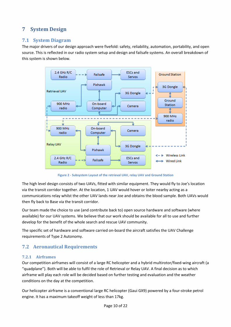
7.1 System Diagram The major drivers of our design approach were fivefold: safety, reliability, automation, portability, and open
source. This is reflected in our radio system setup and design and failsafe systems. An overall breakdown of
this system is shown below.
Figure 2 - Subsystem Layout of the retrieval UAV, relay UAV and Ground Station
The high level design consists of two UAVs, fitted with similar equipment. They would fly to Joe’s location
via the transit corridor together. At the location, 1 UAV would hover or loiter nearby acting as a
communications relay whilst the other UAV lands near Joe and obtains the blood sample. Both UAVs would
then fly back to Base via the transit corridor.
Our team made the choice to use (and contribute back to) open source hardware and software (where
available) for our UAV systems. We believe that our work should be available for all to use and further
develop for the benefit of the whole search and rescue UAV community.
The specific set of hardware and software carried on-board the aircraft satisfies the UAV Challenge
requirements of Type 2 Autonomy.
7.2 Aeronautical Requirements
7.2.1 Airframes
Our competition airframes will consist of a large RC helicopter and a hybrid multirotor/fixed-wing aircraft (a
“quadplane”). Both will be able to fulfil the role of Retrieval or Relay UAV. A final decision as to which
airframe will play each role will be decided based on further testing and evaluation and the weather
conditions on the day at the competition.
Our helicopter airframe is a conventional large RC helicopter (Gaui GX9) powered by a four-stroke petrol
engine. It has a maximum takeoff weight of less than 17kg.

Page 11 of 22
Our quadplane airframe is based on the “Pilatus Porter”, a large scale model aircraft, with the addition of
large vertical lift propellers mounted on the wings. It is powered by a two-stroke IC petrol engine for
forward flight and with large electric motors for vertical flight. It has a maximum take-off weight of less
than 16kg.
The stall speed of the quadplane airframe in fixed wing flight has been calculated to be below 28 kts. Both
the helicopter and quadplane (in vertical flight mode), however, are able to hover at zero airspeed.
On the quadplane airframe in horizontal flight mode, the Pixhawk will ensure that the aircraft’s current
airspeed is a sufficient margin above the stall speed in order to maintain adequate manoeuvrability
throughout the flight. This will be achieved via the on-board sensors including the pitot tube based airspeed
sensor, combined with the Total Energy Control System (TECS) in the flight software. This ensures the
aircraft is able to control its speed and manoeuvrability on an energy (kinetic and potential) basis. The
quadplane will automatically engage the vertical lift motors at airspeeds below 36 knots. This is a
comfortable margin above the stall speed of 28 kts.
The cruise airspeed of both airframes is 56 kts.
Both airframes are using the Pixhawk autopilot platform running the APM software – an open source
autopilot designed for autonomous vehicles. The advantage of using the APM software is that we can easily
customise and debug the software to fit in with the requirements of the OBC, such as the geofencing
requirement. The Pixhawk will feature dual GPS receivers and will be capable of carrying out the full
mission (automated waypoint travel, automated takeoff and automated landing) in conjunction with the
on-board mission control computer. The Pixhawk also features a redundant power supply, with power
coming from two separate sources.
The Pixhawk can be switched to a manual flight mode when in visual range. In this mode the RC pilot
directly controls navigation of the UAV. The geofencing and other safety systems remain active in manual
flight.
7.2.2 Ground Station
The associated ground station will consist of between 3 and 4 laptops running the “MAVProxy” GCS
software. Both radio telemetry links will be routed to all GCS laptops, such that a single laptop failure will
not cause a mission termination. A TV will be used to clearly display both position and status of the UAVs. A
NMEA output (via a MAVProxy module) will be provided from the GCS laptops. All AMSL altitudes reported
from the GCS will be pressure altitudes.
7.2.3 Arming and E-stop
On both the helicopter and quadplane platforms an arming switch and external LED will be used to enable
Outback Joe to indicate when the mission should be resumed after landing at the retrieval site. The LED will
be green when the aircraft is safe to approach. After the press-button arming switch is pushed the LED will
start flashing red to indicate that a 60 second countdown to takeoff has begun. At the end of the 60 second
countdown the LED will go solid red and the aircraft will resume its mission with an automatic takeoff. Both
the arming switch and LED will be labelled to indicate their function.
On the helicopter, the e-stop system will consist of a plug mounted on the side of the main fuselage and
connected by a short cord to the fuselage. The plug will be in series with the power supply for the radios
and ignition systems. Removing the plug will create an open circuit in the power supply for both systems,
rendering them safe. The plug will be of a type commonly used for arming of electric model aircraft. A
descriptive label will be clearly visible next to the arming plug.

Page 12 of 22
On the quadplane, the e-stop will consist of a latching, red, e-stop button with yellow surround and
appropriate wording and will be mounted on top of the fuselage. When pushed, the e-stop will isolate
power to relays/opto-isolators located within critical circuits in the UAV power system, which can be
confirmed by all status indicating LEDs switching off. The relays/opto-isolators will be located between the
battery and IC ignition system for the forward flight IC engine, between the batteries and ESCs for the
vertical lift motors and between the avionics power supply and radio modules for the radio systems.
Activation of the e-stop will remove power to all the relays/opto-isolators which will de-energise all the
aforementioned systems.
7.3 Control and Termination System Design The Control and Termination System (C&TS) is contained within the Pixhawk platform, but running on a
separate CPU with appropriate failsafe software. It will continuously monitor the autopilot. The state
diagram for this system is shown below in Figure 3.
In combination with the main autopilot CPU, it will continually monitor the avionics systems and activate
the fail-safe modes as per the UAV Challenge requirements outlined in Section 3 of the rules when a failsafe
criterion is satisfied, or when commanded by the ground station.
Figure 3 - Failsafe State Diagram
7.4 Flight Termination Method Analysis The flight termination method will be in accordance with Section 9.1 of this report. The termination will be
carried out by an independent CPU on the Pixhawk flight controller, which has exclusive access to the servo
and ESC signal lines. Based on ground testing, the control surfaces go to failsafe positions in less than 1
second after the command being issued by the ground control station.
For the helicopter airframe activation of termination will immediately cut ignition and throttle to the
engine. The aircraft will enter an emergency descent state, holding its current position. We estimate that
from an initial cruise speed of 58 knots and altitude of 400 feet the UAV will impact the ground within 30
meters from the point that termination was activated.

Page 13 of 22
For the quadplane airframe activation of termination will cut power to the vertical lift motors and set all
fixed wing control surfaces to maximum deflection. Ignition to the IC engine will be cut, and throttle set to
zero. Simulation testing indicates that for a geofence breach at cruise airspeed of 56 knots at an altitude of
400 feet the aircraft will impact the ground within 200 meters of the point that termination was activated.
This assumes worst case wind conditions of a 25 knot tail wind.
Out of the scenarios listed above, the maximum either UAV could travel past the geofence in a worst-case
scenario is 200m.
7.5 Geofence system design If the autopilot detects a mission boundary violation (either horizontal or vertical) it will raise a signal on
the C&TS, which will initiate flight termination. Mission boundary edges and altitude limits will be
programmed into the autopilot’s non-volatile memory and checked during pre-flight prep.
This system has been verified to work through extensive simulation and real world testing with prototype
airframes. The CanberraUAV geofencing system has been adopted as a standard feature in the APM
software suite.
Any lockup or failure of this function on the CPU or associated sensors will be treated as an Autopilot lock-
up (Section 9.5) and will result in the C&TS system being activated.
A “soft geofence” will be used to alert the ground station via audible signal when the aircraft's current
course is predicted to take it within 50m of the actual geofence. For the vertical component, a dataset of
terrain data for the local area will be available to the aircraft. Combined with the GPS altitude, the AGL
altitude can be determined and used to ensure the aircraft remains in the altitude (AGL) envelope as a “soft
geofence”.
7.5.1 Altitude Geofence
The barometer on board will be referenced via QNH before flight. This will be used to enforce the 1500 ft
AGL vertical component of the geofence.
On barometer failure, the autopilot will start to use GPS based altitude but with a safety margin of 500ft. If
the GPS loses lock or detects an altitude of above 1000 ft AGL the C&TS system will be activated.
7.6 Radio Equipment There will be three independent radio links to each UAV. This includes a standard 2.4 GHz RC link for
manual control, a 915-928 MHz low bandwidth link for telemetry and a 3G mobile phone network
connections (via USB dongles) for a backup telemetry links. Constant communication with the UAVs will be
maintained through these redundant links. Failover between the links is handled automatically by the APM
and ground station software.
The relay aircraft 915-928 MHz telemetry radio will be setup both as a relay for messages between the GCS
and retrieval aircraft and as a telemetry link for the relay aircraft.
The 915-928 MHz is licenced under the ACMA LIPD class licence (Item 52) and the 3G dongles will use the
standard 3G frequency bands (850MHz, 900MHz and 2100 MHz). All radios used will be “C-Tick” compliant.
The telemetry link has been confirmed to consistently work at 30km range via the relay UAV at the desired
data rate.
Page 14 of 22
8 Risk Assessment
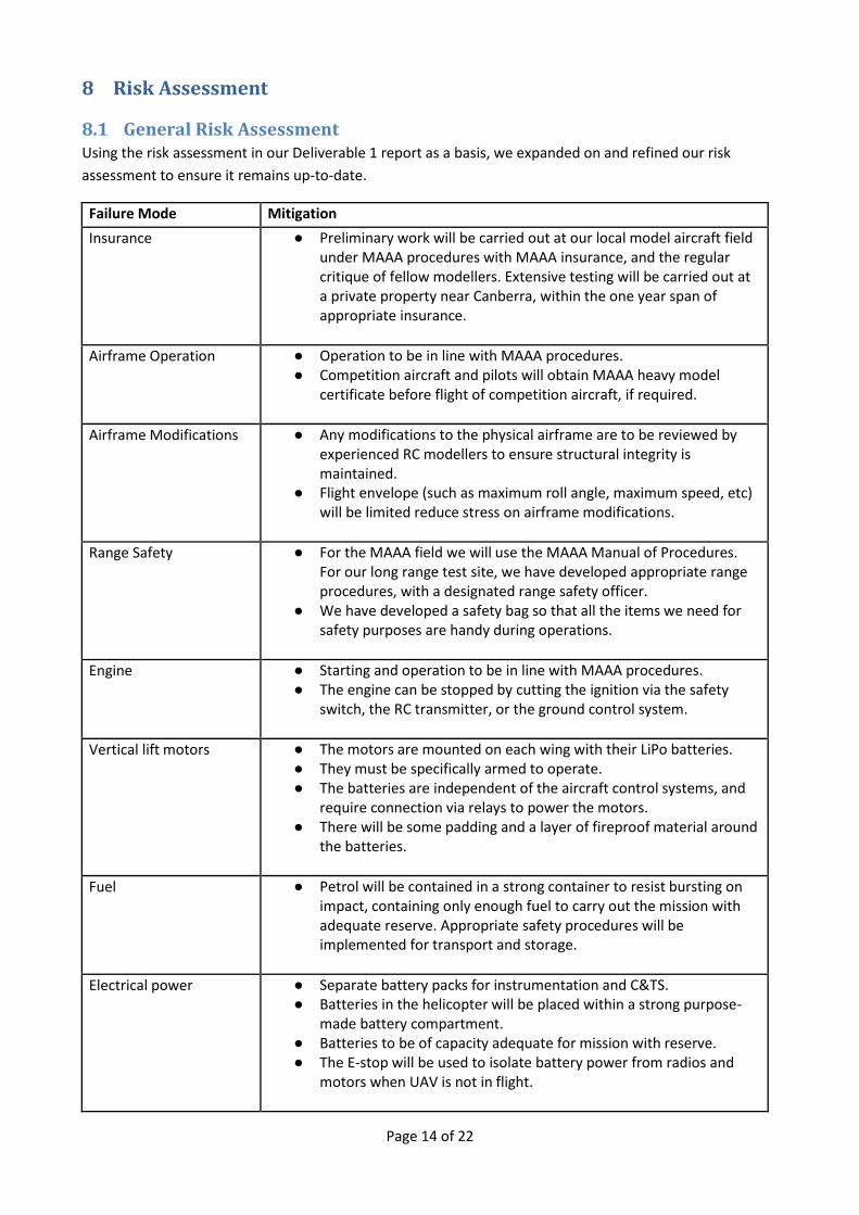
8.1 General Risk Assessment Using the risk assessment in our Deliverable 1 report as a basis, we expanded on and refined our risk
assessment to ensure it remains up-to-date.
Failure Mode Mitigation
Insurance ● Preliminary work will be carried out at our local model aircraft field under MAAA procedures with MAAA insurance, and the regular critique of fellow modellers. Extensive testing will be carried out at a private property near Canberra, within the one year span of appropriate insurance.
Airframe Operation ● Operation to be in line with MAAA procedures. ● Competition aircraft and pilots will obtain MAAA heavy model
certificate before flight of competition aircraft, if required.
Airframe Modifications ● Any modifications to the physical airframe are to be reviewed by experienced RC modellers to ensure structural integrity is maintained.
● Flight envelope (such as maximum roll angle, maximum speed, etc) will be limited reduce stress on airframe modifications.
Range Safety ● For the MAAA field we will use the MAAA Manual of Procedures. For our long range test site, we have developed appropriate range procedures, with a designated range safety officer.
● We have developed a safety bag so that all the items we need for safety purposes are handy during operations.
Engine ● Starting and operation to be in line with MAAA procedures. ● The engine can be stopped by cutting the ignition via the safety
switch, the RC transmitter, or the ground control system.
Vertical lift motors ● The motors are mounted on each wing with their LiPo batteries. ● They must be specifically armed to operate. ● The batteries are independent of the aircraft control systems, and
require connection via relays to power the motors. ● There will be some padding and a layer of fireproof material around
the batteries.
Fuel ● Petrol will be contained in a strong container to resist bursting on impact, containing only enough fuel to carry out the mission with adequate reserve. Appropriate safety procedures will be implemented for transport and storage.
Electrical power ● Separate battery packs for instrumentation and C&TS. ● Batteries in the helicopter will be placed within a strong purpose-
made battery compartment. ● Batteries to be of capacity adequate for mission with reserve. ● The E-stop will be used to isolate battery power from radios and
motors when UAV is not in flight.
Page 15 of 22
Failure Mode Mitigation
Connections, wiring and
soldering
● To be carried out by experienced electronics technician with years of experience in model aircraft and marine electronics in the field.
Autopilot ● Loss of the Autopilot's heartbeat will be detected by the C&TS and appropriate actions taken.
Geofencing system
failure
● Failure of the system running the geofencing program will alert the C&TS by loss of the heartbeat.
Fly away of UAV ● Extensive practice at test range to UAV Challenge rules (including geo-fencing), but with a soft termination to be carried out by the C&TS.
● Low energy VTOL takeoffs will be employed to enable long reaction times.
Rescue of lost UAV ● Procedures to be put in place by our experienced bushwalker prior to field testing.
Bugs in software ● Will use Software In The Loop (SITL) simulation testing to verify software and autopilot hardware, and reduce risk of software bugs.
● We have a range of smaller test aircraft and helicopters on which we test our software and practice our procedures.
Configuration
management
● We are using best software industry practice for configuration management and software version control.
Fatigue/illness of
personnel
● Fatigue and readiness to participate are actively managed during our activities.
● Team members participating on the site able to perform the role of another if required.
Damage to blood sample
on return journey
● Blood sample container will be padded and placed away from heat sources.
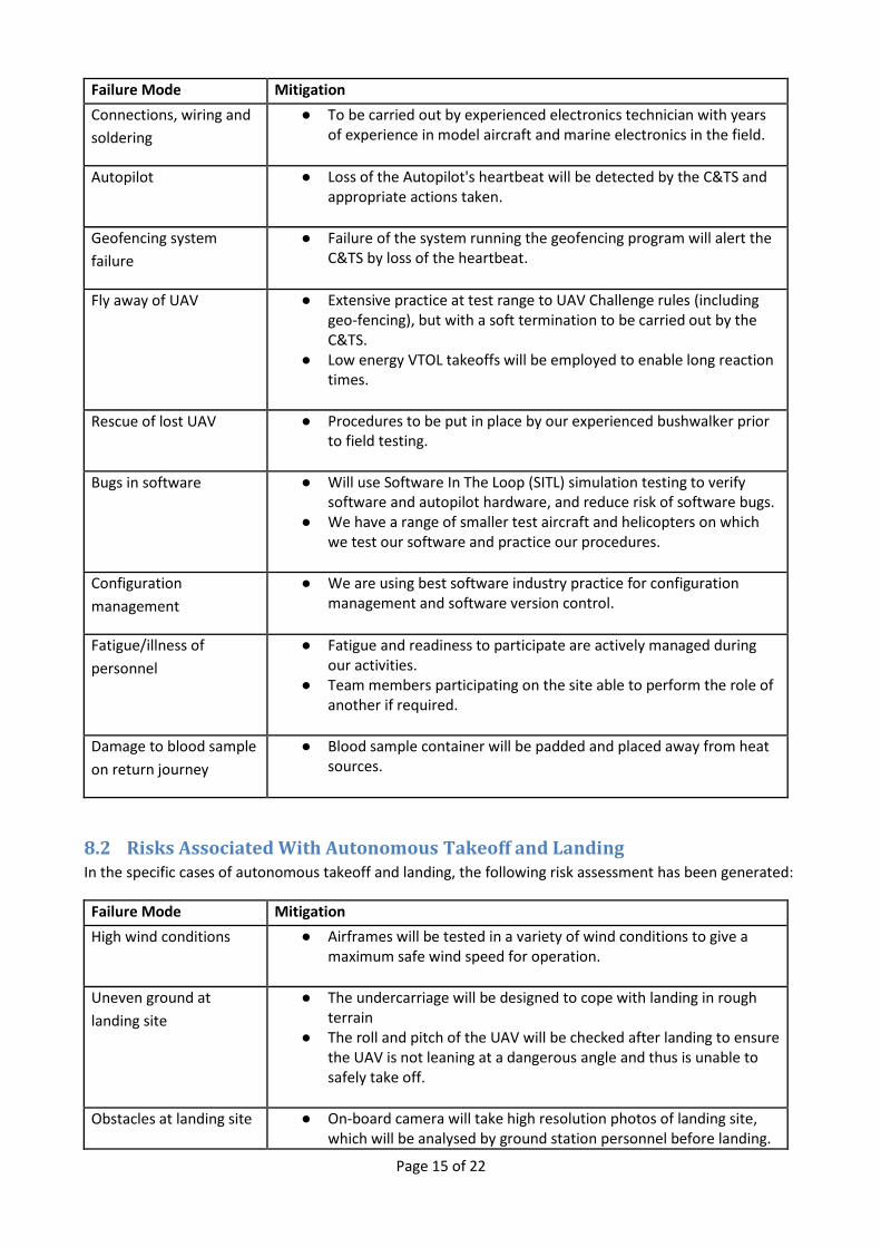
8.2 Risks Associated With Autonomous Takeoff and Landing In the specific cases of autonomous takeoff and landing, the following risk assessment has been generated:
Failure Mode Mitigation
High wind conditions ● Airframes will be tested in a variety of wind conditions to give a maximum safe wind speed for operation.
Uneven ground at
landing site
● The undercarriage will be designed to cope with landing in rough terrain
● The roll and pitch of the UAV will be checked after landing to ensure the UAV is not leaning at a dangerous angle and thus is unable to safely take off.
Obstacles at landing site ● On-board camera will take high resolution photos of landing site, which will be analysed by ground station personnel before landing.

Page 16 of 22
Failure Mode Mitigation
Unseen damage to
airframe during landing
● After landing, systems will be checked for abnormal readings via telemetry. Takeoff will be aborted if telemetry indicates damage to flight controller, radio or battery systems.
Airframe safety to
nearby people after
landing
● UAV will disarm all propulsion motors and engines upon landing.
Page 17 of 22
9 Risk Management Managing the safety of people, property and the aircraft is at the forefront of all of our design and testing
activities. We manage and reduce overall risk by ensuring we have redundancy in all mission critical
systems, the use of on-board failsafe systems and thorough ground testing and checklist procedures before
flight.
In designing our system, we started by building a risk management matrix, identifying possible modes of
failure and evaluated risk mitigation measures. This risk management matrix considered the consequence
and likelihood of potential hardware and software failures.
The following section will outline our risk management approach for key items as outlined in the
requirements for Deliverable 2.
9.1 Flight Termination We are using a control and termination system (C&TS) on board the Pixhawk’s secondary processor. This
module, although on the same physical board as the autopilot, is completely independent. The necessary
software development has been completed, tested and incorporated into our baseline flight management
system.
This system was confirmed as meeting the Outback Challenge failsafe requirements in an email from the
UAV Outback Challenge Technical Committee on March 6th 2014.
The C&TS will implement the primary OBC S&R FTS option for the quadplane using fixed maximum servo
positions and zero motor power. For the helicopter, termination is implemented by cutting ignition. The
C&TS will monitor the autopilot and will control flight surface, ESC and throttle servos, following the
specific procedures outlined in the following sections. Flight termination can also be initiated by the GCS
through controls to the autopilot via the redundant telemetry links.
In case of flight termination activation, the servo and ESC positions for the quadplane will be forced by the
C&TS system to be:
Throttle closed
Full up elevator
Full right rudder
Full down on the right aileron and full up on the left aileron
Zero throttle on vertical lift motors
Ignition cut on the IC engine
If the flight termination mode is activated by any of the conditions described in Sections 9.2-9.6 it cannot
be deactivated.
9.2 Loss of data link The on-board mission computer monitors data link integrity via MAVLink heartbeat messages sent from the
GCS at a rate of 2Hz. On loss of data link for 10 seconds, the UAV will loiter at its current position. If data
link is not re-established within 2 minutes, the UAV will then fly back to Base and loiter for 2 minutes.
During this time the safety pilot will attempt control via visual line of sight. If line of sight RC control is not
possible flight termination will be initiated. If RC control is possible the safety pilot will land the UAV. Flight
outside the mission boundary at any time will cause flight termination including during a loss of data link.

Page 18 of 22
For the specific case of the retrieval aircraft losing data link during the landing descent at the remote site
the automated landing will continue. The aircraft will not allow for takeoff and continuation of the mission
unless the data link is regained.
9.3 Engine Failure The aircraft will have electronic engine monitoring. In case of engine or ignition failure, the UAV will initiate
a controlled glide or autorotation (with the ignition off) towards the base waypoint. If the aircraft achieves
visual range of the airfield the safety pilot will be able to control the glide via the standard RC transmitter
link. If visual range of the safety pilot is not achieved the plane will land as best it can within the mission
boundary. All other failsafe systems remain active during this procedure and will initiate a full flight
termination if needed.
In the case of the quadplane, the vertical lift motors can be used to safely land the UAV in case of failure of
the IC engine. The vertical lift motors will be arranged in such a way (such as an X8 configuration, for
example) that a single vertical lift motor failure can be compensated by the remaining motors.
9.4 Loss of GPS Position In Loss of GPS Position mode the quadplane will slowly circle for 30 seconds, waiting for GPS signal. If there
is no signal after 30 seconds then the autopilot will start dead-reckoning to the base waypoint via the
Transit Corridor. During dead reckoning the on-board sensors will be used to monitor the UAV’s status. If
the UAV’s position within the mission boundary becomes uncertain or the link to GCS is lost during a period
of GPS failure then flight termination will be initiated.
On a second Loss of GPS Position, the quadplane will dead-reckon to the base waypoint (via the transit
corridor) and loiter for 2 minutes to allow a manual landing by the pilot. If this is not possible then flight
termination will be activated. If the planes position within the mission boundary becomes uncertain or the
link to GCS is lost during a period of GPS failure then flight termination will be initiated.
Unless under manual control by the safety pilot, loss of data link while in Loss of GPS Position mode will
cause an immediate flight termination.
For the helicopter Loss of GPS Position mode will cause a position hold for two minutes. If GPS position is
not regained after two minutes the helicopter will land immediately at its current position. Due to the
unreliability of dead-reckoning on rotary wing aircraft dead-reckoning will not be attempted for the
helicopter.
9.5 Autopilot lock-up The autopilot will provide a 10 Hz heartbeat signals to the C&TS system via a dedicated high-speed serial
line. If the autopilot fails to provide a heartbeat for a period of 1 second, the flight will be terminated by the
C&TS system.
9.6 Failure of Ground Control Station If an autopilot detects no communications heartbeat signal from the GCS for a period of 10 seconds then
the loss of data link procedure described above will be initiated. Note that in our design the ground station
has multiple communication links (on different frequencies) to the aircraft and is able to automatically
switch between the links to minimise the chance of link loss.

Page 19 of 22
9.7 Li-Po Battery and Fuel Management Fuel will be stored in AS/NZS 2906:2001 standard jerry cans when not required for UAV operations. The
UAV will only be fuelled shortly before a mission and will only contain an appropriate amount of fuel to
complete the mission, with some reserve.
Li-Po batteries will be stored in fireproof containers when not in use. These boxes will be stored away from
flammable or combustible objects at all times. Battery recharging will be performed away from flammable
or combustible materials. In all cases a fire extinguisher will be nearby in case of emergency
The battery condition and voltage will be checked before and after recharging and before use in a UAV
flight. Any batteries showing bad voltages or showing signs of puffing will be marked as “not good” and will
not be used.
9.8 Other risks identified in risk management section
9.8.1 Bugs in Software
All aircraft software and hardware is thoroughly tested before being used in flight. The testing regime
includes simulation where possible and small scale testing before being used in the final aircraft.
Our testing methodology is:
Design and build new component or feature
Software simulation testing where possible
Hardware simulation testing where possible
Short and long range test flights
Acceptance
We make extensive use of additional test airframes for testing new features.
9.8.2 Range Safety
Short range tests are performed at Canberra Model Aircraft Club (CMAC), where we follow all MAAA and
CMAC rules and procedures.
We have developed a range safety plan for use at our long distance testing facility. The focus of this plan is
on physical safety and on ensuring that personnel have defined roles and responsibilities. This includes the
position of “safety officer” who will oversee the day's flying activities and ensure that all procedures are
followed.

Page 20 of 22
10 Flight Test Results and Discussion
10.1 Project Status As of March 2016, CanberraUAV has achieved the following:
Successfully trialled the Pixhawk flight controller as an autonomous helicopter flight controller
Developed the APM software to support quadplanes
Built and tested a number of small and large quadplane and helicopter airframes
Successfully trialled electric staters for IC engines
10.2 Results
10.2.1 Test Flights
CanberraUAV has built up a small fleet of helicopters and quadplanes of various sizes in order to assist with
our development.
Figure 4 - Two of our test airframes. The quadplane Telemaster (L) and Trex-700 helicopter (R).
These test flights have allowed us to refine both the hardware and software required to control vertical
takeoff and landing airframes.
The hardware part has consisted of evaluating different airframes for their suitability in carrying out a long-
range mission and being able to remotely start their engines. In the case of the quadplane, we have gone
through many iterations of vertical lift systems in order to have enough power to safely lift the fixed-wing
airframe whilst not requiring excessive numbers of batteries or complicated electrical systems.
The software (APM:Plane) has been greatly enhanced to support quadplanes with automatic transition
between horizontal and vertical flight modes. The APM:Copter software (used on the helicopters) has been
further refined to be more reliable and accurate in large helicopter airframes.
We have researched and tested many different electrical power systems to develop a system capable of
handling the high current spikes caused by the manipulation of the helicopter's main rotors at a high

Page 21 of 22
response rate. The power supplies were tested for their ability to supply large amounts of transient current
with a minimal response time whilst maintaining the required voltage.
In terms of helicopter control, a flybarless (FBL) gyro was fitted between the Pixhawk and collective servos
in order to allow safe manual control of the helicopter. To do this, the APM software on the Pixhawk was
altered to output the standard 4-channel AETR (aileron, elevator, throttle and rudder) values over PWM
which would then be converted into values for the collective and tail rotor. With safe manual control
available at all times, helicopter development is both safer and faster.
Figure 5 – The Gaui GX9 with Pixawk and FBL rate controller
This has all been combined with lots of test flights! We have several workhorse test aircraft that we use to
test out the new systems as we develop them - logging dozens of hours of test fights, and spending
countless hours analysing logs to ensure that the systems we develop work as expected.
We hope that all of our work will result in us putting in a good showing at the 2016 Medical Express,
although of course we realise that things can go wrong on the day!

Page 22 of 22
11 Conclusions By using a design approach based upon safety and reliability and learning from our experiences at the 2012
and 2014 Outback Challenges, we are well on our way to presenting a more mature, more effective and
more reliable system for the 2016 UAV Challenge.
At this point in time, all of our airframes have been tested, with developmental testing broadly complete.
Our operational test and evaluation program is progressing smoothly and we plan to run as many flight
tests as practical before October 2016.
We are very pleased with our results so far andthrough the continued hard work of our team members, we
are on track to have a capable and reliable system well before the competition deadline.
The next challenge for us is to integrate our long range telemetry and camera systems, which are
incremental improvements on the reliable systems have developed and used over the past 5 years.
We are looking forward to meeting the other teams in September and competing in the 2016 Medical
Express!