
Definition of Moby Dick Trial Scenarios - ipv6-es.com€¦ · Moby Dick WP5 1 / 1 IST-2000-25394...
38
Moby Dick WP5 1 / 1 IST-2000-25394 Project Moby Dick D0501 Definition of Moby Dick Trial Scenarios Contractual Date of Delivery to the CEC: February 28, 2001 Actual Date of Delivery to the CEC: February 28, 2002 Author(s): partners in WP5 (cf. page 3) Participant(s): partners in WP5 Workpackage: WP5 Security: Public Nature: Report Version: 1.0.1 Total number of pages: 37 Abstract: This document provides the definition of the field trial environment and tests to be carried in the framework of the Moby Dick project. Keyword list: field trial, validation, test-bed.
Transcript of Definition of Moby Dick Trial Scenarios - ipv6-es.com€¦ · Moby Dick WP5 1 / 1 IST-2000-25394...
Moby Dick WP5 1 / 1
IST-2000-25394 Project Moby Dick
D0501
Definition of Moby Dick Trial Scenarios
Contractual Date of Delivery to the CEC: February 28, 2001 Actual Date of Delivery to the CEC: February 28, 2002 Author(s): partners in WP5 (cf. page 3) Participant(s): partners in WP5 Workpackage: WP5 Security: Public Nature: Report Version: 1.0.1 Total number of pages: 37 Abstract: This document provides the definition of the field trial environment and tests to be carried in the framework of the Moby Dick project. Keyword list: field trial, validation, test-bed.
D0501.doc Version 1.0 28.02.2002
Moby Dick WP5 2 / 37
D0501.doc Version 1.0 28.02.2002
Moby Dick WP5 3 / 37
Executive Summary
This documents identifies all the issues relevant to the filed trial to be set-up by the consortium of the Moby Dick project. It recaps the framework for the field trial and specifies the environment for tests in which experts and real users will evaluate the network. This includes specification and placement of hardware and software components of the field trial, specification of the networking technologies and interconnections.
The paper also gives an overview of the tests to be carried and evaluation methods. The detailed specification of the individual tests and procedures will be provided as an Annex to this document.
D0501.doc Version 1.0 28.02.2002
Moby Dick WP5 4 / 37
Authors
Partner Name Phone / Fax / E-mail
UKR Piotr Pacyna Phone: +48-12-6174040 Fax: +48-12-6342372 E-mail: [email protected] Janusz Gozdecki Phone: +48-12-6173599 Fax: +48-12-6342372 E-mail: [email protected] Zdzisław Papir Phone: +48-12-6173937 Fax: +48-12-6342372 E-mail: [email protected]
UC3M Jose Ignacio Moreno Phone: +34-916249183 Fax: +34-916248749 E-mail: [email protected] Ignacio Soto Phone: +34-91-624-5974 Fax: +34-91-624-8749 E-mail: [email protected] Pablo Serrano Phone: +34-916245974 Fax: +34-916248749 E-mail: [email protected] Antonio Cuevas Phone: + 34-91-624 8785 Fax: +34-91-624-8749 E-mail: [email protected]
USTUTT Jürgen Jähnert Phone: +49-711-685-4273 Fax: +49-711-678-8363 E-mail: [email protected]
MOTOROLA Nesrine Chaher Phone: +33-1-69354812 Fax: +33-1-69352501 E-mail:[email protected] Hong-Yon Lach Phone: +33-1-69352536 Fax: +33-1-69352501 E-mail: [email protected] Eric Melin Phone: +33-1-69 35 48 26 Fax: +33-1-69 35 25 01 E-mail: [email protected]
FhG Davinder Pal Singh Phone: +49-30-3463-7175 Fax: +49-30-3463-8175 E-mail: [email protected] Sebastian Zander Phone: +49-30-3463-7287 Fax: +49-30-3463-8287 E-mail: [email protected] Cristian Constantin Phone: +49-30-3463-7146 E-mail: [email protected]
D0501.doc Version 1.0 28.02.2002
Moby Dick WP5 5 / 37
Adrian van der Werf Phone: +49-30-3463 7139 Fax: +49-30-3463 8170 E-mail: [email protected]
EURECOM Michelle Wetterwald Phone: +33-4-93002631 Fax: +33-4-93002627 E-mail: [email protected]
ETHZ Burkhard Stiller Phone: +41-1-632-7016 Fax: +41-1-632-1035 E-mail: [email protected] H. Hasan Phone: +41-1-632-7012 Fax: +41-1-632-1035 E-mail: [email protected]
NEC Amardeo Sarma Phone: +49-62-21-13708-19 Fax: +49-6221-90511-55 E-mail: [email protected] Ralf Schmitz Phone: +49-6221-13 70 8-12 Fax: +49-6221-13 70 8-28 E-mail: [email protected] Xavier Pérez Phone: +49-6221-13708-15 Fax: +49-6221-90511-55 E-mail: [email protected]
PTIN Victor Marques Phone: Fax: E-mail: [email protected] Rui Aguiar Phone: +35-1-234-381937 Fax: +351.234.381941 E-mail: [email protected]
D0501.doc Version 1.0 28.02.2002
Moby Dick WP5 6 / 37
Table of Contents
ABBREVIATIONS.............................................................................................. 8
1. INTRODUCTION ..................................................................................... 10
2. GENERAL OBJECTIVES ....................................................................... 10
2.1 Requirements from WP2............................................................................................................. 11
2.2 Requirements from WP3............................................................................................................. 11
2.3 Requirements from WP4............................................................................................................. 12
3. FIELD-TRIAL ENVIRONMENT ............................................................... 13
3.1 Network architecture in Madrid ................................................................................................ 13 3.1.1 Adressing ............................................................................................................................... 14 3.1.2 AAAC aspects........................................................................................................................ 14 3.1.3 IPv6 mobility ......................................................................................................................... 14 3.1.4 Wireless network (IEEE 802.11b) ......................................................................................... 15 3.1.5 Quality of Service .................................................................................................................. 15
3.2 Network architecture in Stuttgart .............................................................................................. 15 3.2.1 W-CDMA Frequency............................................................................................................. 16 3.2.2 IP configuration ..................................................................................................................... 17 3.2.3 University of Stuttgart Network Plan..................................................................................... 17
3.3 Interconnection between Madrid and Stuttgart........................................................................ 18 3.3.1 Support for QoS in GÉANT................................................................................................... 19 3.3.2 Connection to GÉANT .......................................................................................................... 19
3.4 Test users ...................................................................................................................................... 20
4. SPECIFICATION OF HARDWARE AND SOFTWARE........................... 20
4.1 Hardware...................................................................................................................................... 20 4.1.1 Mobile Terminal .................................................................................................................... 20 4.1.2 Bandwidth broker................................................................................................................... 21 4.1.3 AAAC Server......................................................................................................................... 21 4.1.4 Radio Gateway....................................................................................................................... 21 4.1.5 Access Router ........................................................................................................................ 22 4.1.6 WLAN Access Router ........................................................................................................... 22
4.2 Software ........................................................................................................................................ 23 4.2.1 MIPLv6.................................................................................................................................. 23 4.2.2 AAAC System server............................................................................................................. 23 4.2.3 AAAC Attendant ................................................................................................................... 23 4.2.4 NeTraMet System .................................................................................................................. 23 4.2.5 QoS Broker ............................................................................................................................ 24 4.2.6 DiffServ ................................................................................................................................. 24 4.2.7 Radio Gateway....................................................................................................................... 24 4.2.8 MT Middleware ..................................................................................................................... 25 4.2.9 WCDMA Access Stratum...................................................................................................... 25
D0501.doc Version 1.0 28.02.2002
Moby Dick WP5 7 / 37
4.3 Other software tools..................................................................................................................... 26 4.3.1 CVS........................................................................................................................................ 26 4.3.2 Tests tools .............................................................................................................................. 26
4.4 Applications.................................................................................................................................. 26
5. TEST PLAN............................................................................................. 27
5.1 Objectives and methods for Phase 1........................................................................................... 27
5.2 Objectives and methods for Phase 2........................................................................................... 28
5.3 Objectives and methods for Phase 3........................................................................................... 28
5.4 System capabilities tests .............................................................................................................. 28 5.4.1 IPv6 on fixed-network nodes ................................................................................................. 28 5.4.2 MIPv6 on Mobile Node ......................................................................................................... 28 5.4.3 Fast Handover ........................................................................................................................ 28 5.4.4 Registration............................................................................................................................ 29 5.4.5 AAAC Server / Authorization................................................................................................ 29 5.4.6 Policy Engine ......................................................................................................................... 30 5.4.7 Metering................................................................................................................................. 30 5.4.8 Accounting............................................................................................................................. 30 5.4.9 AAAC System and QoS Interaction ...................................................................................... 30 5.4.10 Resource allocation................................................................................................................ 31
5.5 Communications capability tests ................................................................................................ 31 5.5.1 Reachability ........................................................................................................................... 31
5.5.1.1 Static trials ......................................................................................................................... 32 5.5.1.2 Mobility trials..................................................................................................................... 32
5.5.2 UDP Transmission ................................................................................................................. 33 5.5.2.1 Static trials ......................................................................................................................... 33 5.5.2.2 Mobility trials..................................................................................................................... 34
5.5.3 TCP transmission ................................................................................................................... 36
6. EVALUATION ......................................................................................... 36
6.1 Expert evaluation in field trial.................................................................................................... 37
6.2 Expert evaluation in simulation.................................................................................................. 37
6.3 User evaluation............................................................................................................................. 37
7. SUMMARY .............................................................................................. 37
8. REFERENCES ........................................................................................ 37
D0501.doc Version 1.0 28.02.2002
Moby Dick WP5 8 / 37
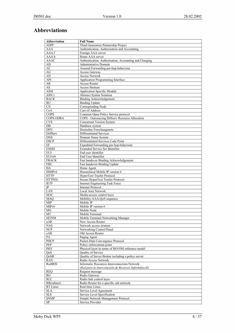
Abbreviations
Abbreviation Full Name 3GPP Third Generation Partnership Project AAA Authentication, Authorisation and Accounting AAA.f Foreign AAA server AAA.h Home AAA server AAAC Authentication, Authorisation, Accounting and Charging AD Administrative Domain AF Assured Forwarding per-hop-behaviour AG Access Gateway AN Access Network API Application Programming Interface AR Access Router AS Access Stratum ASM Application Specific Module ASN.1 Abstract Syntax Notation BACK Binding Acknowledgement BU Binding Update CN Corresponding Node CoA Care-of Address COPS Common Open Policy Service protocol COPS-ODRA COPS - Outsourcing Diffserv Resource Allocation CVS Concurrent Version System DB Database system DFN Deutsches Forschungsnetz DiffServ Differentiated Services DNS Domain Name System DSCP Differentiated Services Code Point EF Expedited Forwarding per-hop-behaviour ESSID Extended Service Set Identifier EUI End user identifier EUI-64 End User Identifier FBACK Fast handover Binding Acknowledgement FBU Fast handover Binding Update HA Home Agent HMIPv6 Hierarchical Mobile IP version 6 HTTP HyperText Trasfer Protocol HTTP(S) Secure HyperText Trasfer Protocol IETF Internet Engineering Task Force IP Internet Protocol LAN Local Area Network MAC Media-access control layer MAQ Mobility-AAA-QoS sequence MIP Mobile IP MIPv6 Mobile IP version 6 MN Mobile Node MT Mobile Terminal MTNM Mobile Terminal Networking Manager nAR New Access Router NAS Network access stratum NCP Networking Control Panel oAR Old Access Router PA Paging Agent PDCP Packet Data Convergence Protocol PEP Policy enforcement point PHY Physical layer in terms of ISO/OSI reference model QoS Quality of Service QoSB Quality of Server Broker including a policy server RAN Radio Access Network RedIRIS Informatic Resources Interconnection Network
(Red para la Interconexión de Recursos InformáticoS) REQ Request message RG Radio Gateway RLC Radio link control layer RR(subnet) Radio Router for a specific sub network RT Linux Real-time Linux SLA Service Level Agreement SLS Service Level Specification SNMP Simple Network Management Protocol SP Service Provider
D0501.doc Version 1.0 28.02.2002
Moby Dick WP5 9 / 37
Ssh Secure shell application UPS User profile subset UPS User Profile Specification URP User Registration Process VoIP Voice over IP W-CDMA Wideband Code Division Multiple Access WLAN Wireless LAN
D0501.doc Version 1.0 28.02.2002
Moby Dick WP5 10 / 37
1. Introduction This document identifies all the issues related to the field trial that will be set-up by the consortium of the Moby Dick project. The document contains a summary of a framework for the field trial, a definition of the field trial, specification of the tests and indications on the assessment methods for the results. The framework for the field trial enlists the most important concepts addressed in the Moby Dick project and shows how these concepts are reflected in the field trial. This description includes: • the motivation for the field trial, and • expectations of the field trial. The framework for field trial is provided in chapter 2 “General objectives”. The definition of the field trial encompasses numerous issues related to the environment in which the experiments will be conducted. These include: • description of the trial sites, • description of the pan-european link interconnecting the trial sites, • definition of the applications to be used, • specification of the hardware to be used in field trial and its capabilities, • specification of software including software components developed in the project, operating systems,
third-party software, and supplementary software. The definition of the field trial is provided in chapter 3 “Field-trial environment“ and 4 “Specification of hardware and software“. The description of the experiments follows in chapter 5 “Test plan“. It contains: • definitions of the trial phases, • objectives for each phase, • definitions of individual experiments. Here some specific configuration options and hints on how to proceed with the tests are provided. The full specification of individual tests and procedures will be provided as an Annex to this document on 30th September 2002. Remarks on the assessment methods and evaluation of the results are given in chapter 6 “Evaluation“.
2. General objectives The Moby Dick project aims to investigate the all-IP concept by means of design, implementation and validation of a heterogeneous all-IP network architecture for seamless wireless Internet access. The network under study incorporates three networking technologies: W-CDMA, 802.11 and Ethernet. We envision that the development of a networking architecture integrating heterogeneous technologies will facilitate access to existing and emerging IP-based communications. The Moby Dick aims to take full advantage of the IP protocol, Mobile IP, AAAC architecture and develop necessary extensions in order to enable end-to-end packet-based mobile services. The architecture is being developed with two key design principles: 1) the network should implement as many control functions as possible using IP protocol;
This includes service access control, mobility control and QoS control; 2) the network should be able to support applications with quality comparable or surpassing the quality
in traditional cellular networks. The objectives of the project have been defined in [annex1] and further discussed in [D0101]. There is a strict relationship between these objectives, and objectives of the field-trial. The field trial, a constituent part of the project, is considered as a validator for the design and the solutions found in the project. The set-up of the field trial is determined by the need to: • validate an integrated architecture incorporating support for QoS, MIPv6 and AAAC, • validate the provisioning of a seamless intra- and inter-technology hand-over, • validate the authentication and authorisation schemes supporting user mobility, • validate the development of a QoS model suitable for a dynamic wireless environment.
D0501.doc Version 1.0 28.02.2002
Moby Dick WP5 11 / 37
2.1 Requirements from WP2 WP2 is concerned with QoS. The purpose of the field trial is to validate the architecture with respect to QoS. In Moby Dick QoS will be provided based on DiffServ and appropriate admission control mechanisms performed by the QoS broker. Apart from admission control and resource provisioning, the QoS broker will also control all the QoS-related interactions with other entities of Moby Dick architecture such as AAAC. WP2 will verify by means of the field trial that the user is able to start any of the applications considered in Moby Dick such as VoIP, www or ftp and confirm that the packet flows generated or received by the application receive treatment that conforms to the Service Level Specification of the user who is using the application. The list of functional features we would like to have in the field trial can be classified into the following main areas:
o Ability to launch applications: here we deal with the full process, beginning with the user starting an application and ending with the final resource provision. Therefore, we are concerned here with:
o The ability to test the QoS provisioning functions. There will be one provisioning function per type of access network.
o The ability to test the underlying signalling such as requests for network resources required mapping functions (from the application requirements to IP QoS and from IP-level QoS to L2 QoS), transfer of the UPS to the QoS Broker, provisioning of the AR, etc.,
o The ability for the same user to launch multiple applications with similar or different QoS requirements.
o Ability to perform handovers: o Ability to perform handovers between different access network technologies.
Here the QoS-related functions are considered such provisioning of the AR. The different handovers shall be performed in the same and different administrative domains.
o Ability to perform handovers between the same technologies, in the same and different administrative domains.
o Ability to release unused resources. With the above objectives the interaction between different QoS entities will be tested. It has been decided that there will be one QoS domain per administrative domain in the field trial, and that inter-QoS-domain signalling will not be implemented (it is considered optional in the scope of WP2).
2.2 Requirements from WP3 The primary focus from the WP3 point of view is to validate the Moby Dick concept with respect to IP-based mobility management, having special requirements on enhanced handover support, as well as on the validation of a concept of IP-based paging support. The validation must be seen in context with the simulation efforts and analytical work within WP3, which complement this validation via implementations and field trial. Simulations and analyses have provided arguments why the project has chosen a fast handover approach proposed in the IETF Mobile IP Working Group, and so far not taken up hierarchical concepts, such as HMIPv6. The field trial should show that the goal to reduce the time needed for handover has been achieved and that data loss has been minimised or eliminated (seamless handover). This should hold for a combination of mobility, AAAC and QoS scenarios. The architecture of Moby Dick shows that additional procedures are needed for AAAC and QoS, which are dependent on mobility procedures and need synchronisation. Adding or synchronising with AAAC and QoS should not build-up excessive delays and should not lead to data loss. To start with, basic mobility functionalities should be demonstrated. These include: • Connection to home or foreign domain by means of registration involving stateless CoA acquisition, • Reachability. The laboratory setup and the field trial should therefore show that the solution chosen within Moby Dick maintains the seamlessness introduced by fast handover. In addition to demonstrating a seamless handover via an application running some real-time service, seamless handover should also be shown by some kind of monitoring system, which show how the messages arrive at or leave the mobile node.
D0501.doc Version 1.0 28.02.2002
Moby Dick WP5 12 / 37
The scenarios chosen for Moby Dick require that seamless handovers should be achieved for the following two scenarios: • Intra-domain, intra-technology handovers, • Intra-domain, inter-technology handovers. Handover should also be shown for: • Inter-domain, intra-technology handovers, • Inter-domain, inter-technology handovers, but the above two types of handover need not to be seamless. For paging, we need to show: • A mobile node entering the dormant mode, • A mobile node recognising that it is leaving the paging area, so it re-registers in the new paging area, • A mobile node “wakes up” and leaves the dormant mode itself, • A corresponding node “wakes up” the dormant mobile node via the paging agent. Paging, as in the case of handover, should be demonstrated not only by applications, but also by a monitoring system that shows how the messages flow between corresponding node, home agent, paging agent and mobile node.
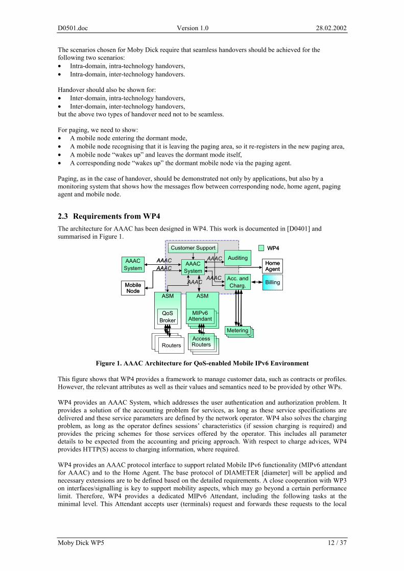
2.3 Requirements from WP4 The architecture for AAAC has been designed in WP4. This work is documented in [D0401] and summarised in Figure 1.
This figure shows that WP4 provides a framework to manage customer data, such as contracts or profiles. However, the relevant attributes as well as their values and semantics need to be provided by other WPs. WP4 provides an AAAC System, which addresses the user authentication and authorization problem. It provides a solution of the accounting problem for services, as long as these service specifications are delivered and these service parameters are defined by the network operator. WP4 also solves the charging problem, as long as the operator defines sessions’ characteristics (if session charging is required) and provides the pricing schemes for those services offered by the operator. This includes all parameter details to be expected from the accounting and pricing approach. With respect to charge advices, WP4 provides HTTP(S) access to charging information, where required. WP4 provides an AAAC protocol interface to support related Mobile IPv6 functionality (MIPv6 attendant for AAAC) and to the Home Agent. The base protocol of DIAMETER [diameter] will be applied and necessary extensions are to be defined based on the detailed requirements. A close cooperation with WP3 on interfaces/signalling is key to support mobility aspects, which may go beyond a certain performance limit. Therefore, WP4 provides a dedicated MIPv6 Attendant, including the following tasks at the minimal level. This Attendant accepts user (terminals) request and forwards these requests to the local
Acc. andCharg. Billing
AAACSystem
Auditing
Customer Support WP4
ASM ASM
AAAC
AAACAAAC
AAACAAACSystem
MobileNode
QoSBroker
Routers
MIPv6 Attendant
AccessRouters
MeteringMeteringMetering
AAACHomeAgent
Acc. andCharg. Billing
AAACSystem
Auditing
Customer Support WP4
ASM ASM
AAAC
AAACAAAC
AAACAAACSystem
MobileNode
QoSBroker
Routers
MIPv6 Attendant
AccessRouters
MeteringMeteringMeteringMeteringMeteringMetering
AAACHomeAgent
Figure 1. AAAC Architecture for QoS-enabled Mobile IPv6 Environment
D0501.doc Version 1.0 28.02.2002
Moby Dick WP5 13 / 37
AAAC System. It replies to user requests based on the response from the local AAAC System. And it configures the relevant security module to monitor the flow of packets from/to the mobile user. The interaction of AAAC System with the QoS Broker will be provided via an Application Specific Module (ASM). From WP4 point of view, this interaction aims at authorising QoS requests coming from the users, however resource availability check and reservation are matters of QoS Broker. Finally, the auditing system will analyse and report whether the service provision and consumption conform to the contract. The trial or demonstration should show the capabilities of the AAAC infrastructure with a policy-driven AAAC System. Unauthenticated user will not be able to get access to the services. However, depending on the business policy, certain minimum functionality, e.g. “emergency call” might be provided for homeless or anonymous user. In any case, service or resource consumption will be accounted for, as long as appropriate means, parameters, and specifications will be available from the operator. It will be a policy-based decision on whether homeless/anonymous user access will be charged or not in a given environment. The above detailed requirements can be summarised in the following major requirements: 1. Policy-driven decision on minimum functionality (services) provided to a homeless and anonymous
user.
2. Only authenticated and authorized users may get access to services they subscribe. Users will be authenticated by the home provider, which requires from the field trial the support of inter-domain AAAC System interactions.
3. Service/resource consumption will be accounted for, however: policy-based decision on whether homeless/anonymous user access will be charged or not.
3. Field-trial environment This chapter provides a picture of the network architecture and defines the positioning and the interconnection of the devices involved in the tests. It defines the access technologies and equipment that will be available in Madrid and Stuttgart trial sites. It does not however, provide a detailed specification of the elements – such description is given in section 4.1 “Hardware” and 4.2 “Software”.
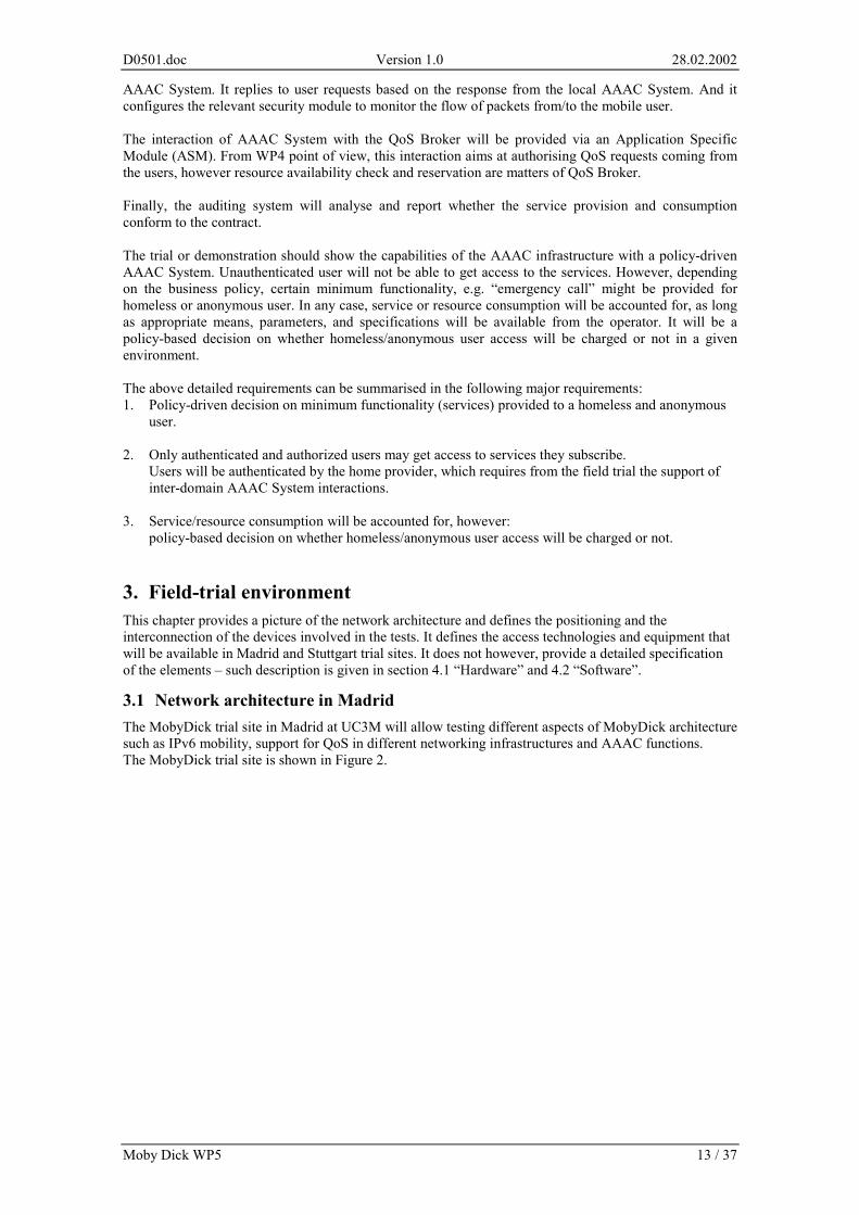
3.1 Network architecture in Madrid The MobyDick trial site in Madrid at UC3M will allow testing different aspects of MobyDick architecture such as IPv6 mobility, support for QoS in different networking infrastructures and AAAC functions. The MobyDick trial site is shown in Figure 2.
D0501.doc Version 1.0 28.02.2002
Moby Dick WP5 14 / 37
Figure 2. Field trial in Madrid
There are six different subnetworks with public IPv6 addresses. Three machines work as routers, another one as AAAC server, QoS broker and home agent, and the rest of them is user equipment, which is connected to a wired subnetwork but also has a WLAN interface.
3.1.1 Adressing The IPv6 addresses belong to the public range assigned to UC3M. The six subnetworks are 2001:0720:0410:1002/64 up to 2001:0720:0410:1007/64. The complete IPv6 address for each interface is formed following the EUI-64 ID. Therefore, every machine has a global IPv6 connectivity and they are registered with DNS. The domain name is ipv6.it.uc3m.es. The complete hostname of every machine in this MobyDick domain is formed by concatenation of the machine name (given in Figure 2) and the domain name.
3.1.2 AAAC aspects UC3M’s infrastructure allows for a large number of AAAC tests to be performed as long as the MN remains in his home domain since we have only one AAAC server that will play the role of the AAAC.h. These will be the elements involved and their functions: Device name function Lombriz MN cucaracha AAAC client escarabajo AAAC server, HA We have all the elements defined in Diameter Mobile IPv6 Application [DiaMIPv6]. For instance, we could test the security associations performed at registration phase.
3.1.3 IPv6 mobility The structure of the UC3M test-bed offers flexibility needed to make different tests that involve several machines and more than one router. With this scenario one can test inter- and intra-technology mobility. There are 4 wired networks and 2 wireless networks, all of them with IPv6 global connectivity. One can test communications between more than one mobile node attached to more than one different foreign network (wired or wireless).
D0501.doc Version 1.0 28.02.2002
Moby Dick WP5 15 / 37
3.1.4 Wireless network (IEEE 802.11b) In order to perform mobility tests, two different wireless networks have been established, so a mobile node will be able to make a handover between these two networks. An ESSID has been assigned to each network: IPv6-WLAN and IPv6-WLAN2. We are using SMC 2632W wireless cards with prism2 chipset [prism]. This driver allows building an access point using a linux machine, with the SMC wireless card. In the scenario, there are two machines acting as access points (APs), as can be seen in Figure 2. The selection of the wireless cards had been based on the requirement of sniffing and injecting IEEE 802.11 raw frames. There are applications that allow us to sniff these frames like prism2dump and ethereal [ethereal] using prism2 chipset based cards.
3.1.5 Quality of Service Several machines are involved in the QoS testing. The QoS broker runs in the machine called escarabajo.ipv6.it.uc3m.es. It will receive requests from pulga.ipv6.it.uc3m.es (simulated access router) which will perform the marking function of the Diffserv architecture, but only in order to test QoS. The real access router in this MobyDick domain is cucaracha.ipv6. The Diffserv core network is simulated with the routers cucaracha.ipv6.it.uc3m.es and termita.ipv6.it.uc3m.es. They will have the necessary elements to provide QoS (queuing disciplines, classes and filters). Different types of tests can be made, for example, from clients in the 2001:0720:0410:1004/64 to wired clients in the 2001:0720:0410:1007/64 or wireless clients in 2001:0720:0410:1007/64.
3.2 Network architecture in Stuttgart The requirements of the Moby Dick trial in Stuttgart are to verify and validate QoS enabled and AAAC supported mobility in the scenarios according to Table 1. Additionally, in every stage transition to the wired, Ethernet based IPv6 network should be possible. The detailed trial experiments will be documented in the annex to this document.
Domain 1 Domain 2 From \ to WLAN WCDMA WLAN WCDMA
WLAN Intra-technology/ Intra- Domain
Inter-technology/ Intra- domain
Intra-technology/ Inter- domain
Intra-technology/ Inter- domain
Domain 1
WCDMA Inter-technology/ Intra- Domain
Intra-technology/ Intra- domain
Intra-technology/ Inter- domain
Inter-technology/ Inter- domain
WLAN Intra-technology/ Inter- Domain
Inter-technology/ Inter- domain
Intra-technology/ Intra- domain
Inter-technology/ Intra- domain
Domain 2
WCDMA Inter-technology/ Inter- domain
Intra-technology/ Inter- domain
Intrra-technology/ Intra- domain
Inter-technology/ Intra- domain
Table 1. Mobility scenarios
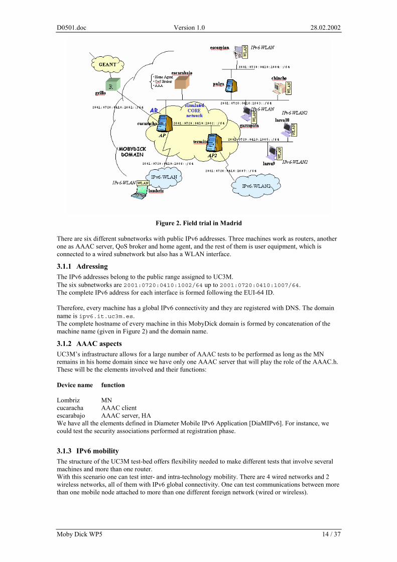
The Moby Dick field trial site at Stuttgart will be located at the campus of the University of Stuttgart in Stuttgart Vaihingen. This is the new campus in the south of Stuttgart where both institutes, the IND and the Computing center RUS are located. Figure 3 shows a detailed plan of the campus.
D0501.doc Version 1.0 28.02.2002
Moby Dick WP5 16 / 37
Figure 3. Campus of the University of Stuttgart
For the Moby Dick trial at Stuttgart, a W-CDMA licence is provided by Deutsche Telekom branch T-Mobil. The three grey circles in the figure show the coordinates and the extension of the trial site. This are mainly the geographic regions around the Buildings Allmandring 30, Allmandring 3a and Pfaffenwaldring 47. The detailed location is according to the Gauss-Krueger-Coordinates, Table 2:
Ort Koordinaten – right
Koordinaten – High
Universität Stuttgart (1) 3507020 5400300 Universität Stuttgart (2) 3507770 5401010 Universität Stuttgart (3) 3507530 5400560
Table 2. Gauss-Krüger coordinates of the Stuttgart trial site
For this region Moby Dick has got the right to use the TDD frequency band of T-Mobile. More details about this spectrum are given in the next sub-section. It is planned to install base stations with a maximum power of 1 Watt within the indicated area.
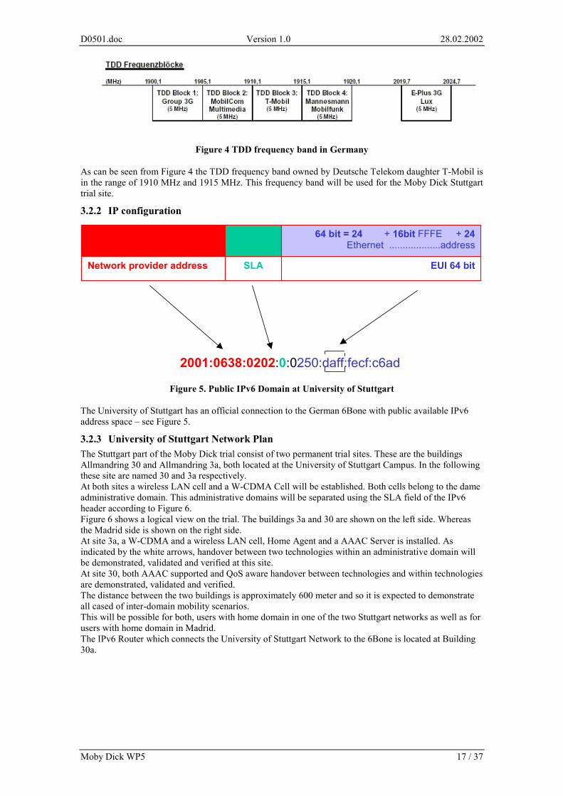
3.2.1 W-CDMA Frequency Figure 4 shows the official frequency plan of the German UMTS spectrum. In Germany there are six licenses distributed. There exists a FDD frequency band between 1920,3 MHZ and 1979,3 MHZ. This band is split into 6 parts and each of the six operators use a 10 MHZ band. Another FDD band is in the range between 2110,3 MHZ and 2169,7 MHZ. Also this spectrum is split up into 6 parts. Additionally there are 5 TDD frequency blocks distributed to 5 operators (see Figure 4).
D0501.doc Version 1.0 28.02.2002
Moby Dick WP5 17 / 37
Figure 4 TDD frequency band in Germany
As can be seen from Figure 4 the TDD frequency band owned by Deutsche Telekom daughter T-Mobil is in the range of 1910 MHz and 1915 MHz. This frequency band will be used for the Moby Dick Stuttgart trial site.
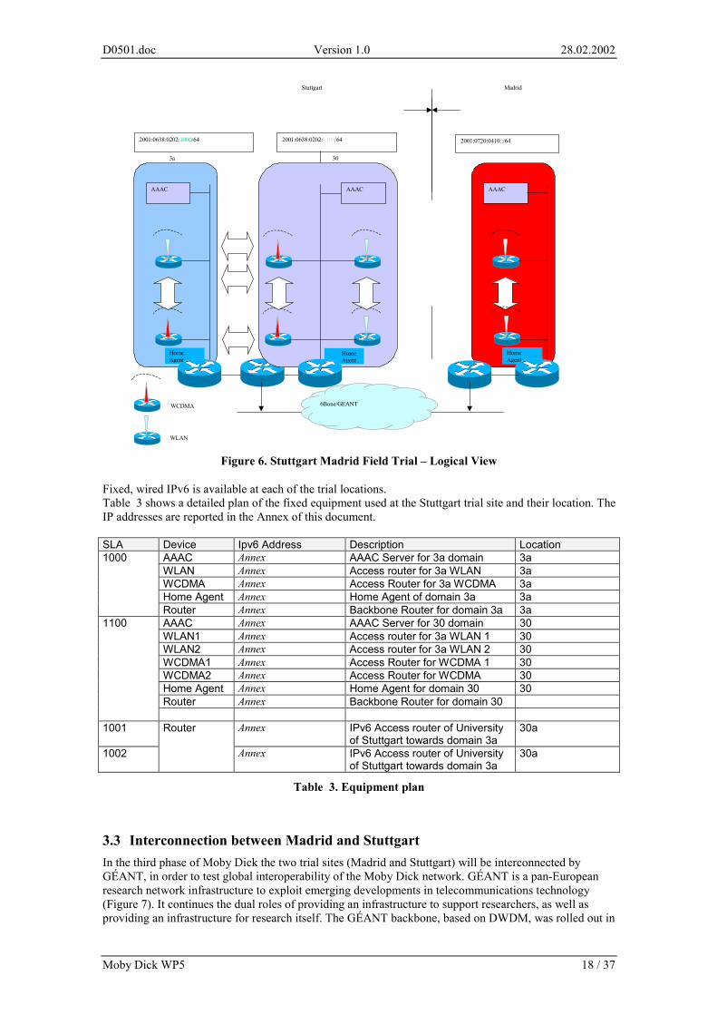
3.2.2 IP configuration
EUI 64 bit SLA Network provider address
64 bit = 24 + 16bit FFFE + 24Ethernet ...................address
16bit 48 bit 2001:0638:0202
2001:0638:0202:0:0250:daff:fecf:c6ad
Figure 5. Public IPv6 Domain at University of Stuttgart
The University of Stuttgart has an official connection to the German 6Bone with public available IPv6 address space – see Figure 5.
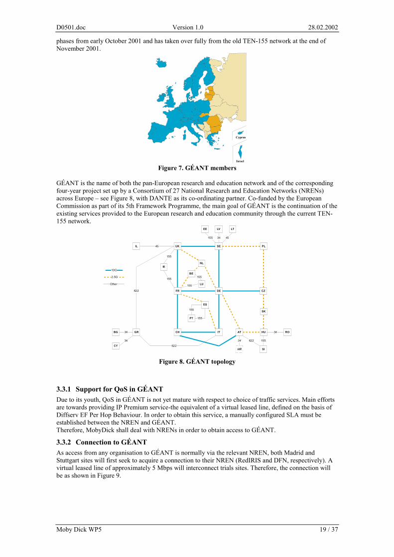
3.2.3 University of Stuttgart Network Plan The Stuttgart part of the Moby Dick trial consist of two permanent trial sites. These are the buildings Allmandring 30 and Allmandring 3a, both located at the University of Stuttgart Campus. In the following these site are named 30 and 3a respectively. At both sites a wireless LAN cell and a W-CDMA Cell will be established. Both cells belong to the dame administrative domain. This administrative domains will be separated using the SLA field of the IPv6 header according to Figure 6. Figure 6 shows a logical view on the trial. The buildings 3a and 30 are shown on the left side. Whereas the Madrid side is shown on the right side. At site 3a, a W-CDMA and a wireless LAN cell, Home Agent and a AAAC Server is installed. As indicated by the white arrows, handover between two technologies within an administrative domain will be demonstrated, validated and verified at this site. At site 30, both AAAC supported and QoS aware handover between technologies and within technologies are demonstrated, validated and verified. The distance between the two buildings is approximately 600 meter and so it is expected to demonstrate all cased of inter-domain mobility scenarios. This will be possible for both, users with home domain in one of the two Stuttgart networks as well as for users with home domain in Madrid. The IPv6 Router which connects the University of Stuttgart Network to the 6Bone is located at Building 30a.
D0501.doc Version 1.0 28.02.2002
Moby Dick WP5 18 / 37
AAAC AAAC
Home Agent
Home Agent
AAAC
Home Agent
2001:0638:0202:1100/64 2001:0638:0202:1000/64 2001:0720:0410::/64
6Bone/GEANT
Madrid Stuttgart
WLAN
WCDMA
3a 30
Figure 6. Stuttgart Madrid Field Trial – Logical View
Fixed, wired IPv6 is available at each of the trial locations. Table 3 shows a detailed plan of the fixed equipment used at the Stuttgart trial site and their location. The IP addresses are reported in the Annex of this document. SLA Device Ipv6 Address Description Location
AAAC Annex AAAC Server for 3a domain 3a WLAN Annex Access router for 3a WLAN 3a WCDMA Annex Access Router for 3a WCDMA 3a Home Agent Annex Home Agent of domain 3a 3a
1000
Router Annex Backbone Router for domain 3a 3a AAAC Annex AAAC Server for 30 domain 30 WLAN1 Annex Access router for 3a WLAN 1 30 WLAN2 Annex Access router for 3a WLAN 2 30 WCDMA1 Annex Access Router for WCDMA 1 30 WCDMA2 Annex Access Router for WCDMA 30 Home Agent Annex Home Agent for domain 30 30 Router Annex Backbone Router for domain 30
1100
1001 Annex IPv6 Access router of University
of Stuttgart towards domain 3a 30a
1002
Router
Annex IPv6 Access router of University of Stuttgart towards domain 3a
30a
Table 3. Equipment plan
3.3 Interconnection between Madrid and Stuttgart In the third phase of Moby Dick the two trial sites (Madrid and Stuttgart) will be interconnected by GÉANT, in order to test global interoperability of the Moby Dick network. GÉANT is a pan-European research network infrastructure to exploit emerging developments in telecommunications technology (Figure 7). It continues the dual roles of providing an infrastructure to support researchers, as well as providing an infrastructure for research itself. The GÉANT backbone, based on DWDM, was rolled out in
D0501.doc Version 1.0 28.02.2002
Moby Dick WP5 19 / 37
phases from early October 2001 and has taken over fully from the old TEN-155 network at the end of November 2001.
Cyprus
Israel Figure 7. GÉANT members
GÉANT is the name of both the pan-European research and education network and of the corresponding four-year project set up by a Consortium of 27 National Research and Education Networks (NRENs) across Europe – see Figure 8, with DANTE as its co-ordinating partner. Co-funded by the European Commission as part of its 5th Framework Programme, the main goal of GÉANT is the continuation of the existing services provided to the European research and education community through the current TEN-155 network.
UK
BE
NL
ITCH
DEFR
SE
AT
LV
PL
SK
CZ
HR
HU
EE LT
LU
622
622
SI
RO
PT
ES
IE
BG
CY
GR
622
34
34
45
155
155
155
155
155
155
34 155
34
155 34 45
10G
2.5G
Other
IL
Figure 8. GÉANT topology
3.3.1 Support for QoS in GÉANT Due to its youth, QoS in GÉANT is not yet mature with respect to choice of traffic services. Main efforts are towards providing IP Premium service-the equivalent of a virtual leased line, defined on the basis of Diffserv EF Per Hop Behaviour. In order to obtain this service, a manually configured SLA must be established between the NREN and GÉANT. Therefore, MobyDick shall deal with NRENs in order to obtain access to GÉANT.
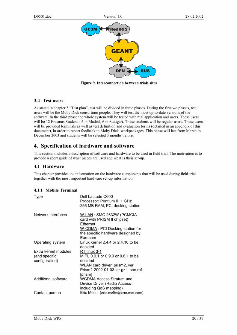
3.3.2 Connection to GÉANT As access from any organisation to GÉANT is normally via the relevant NREN, both Madrid and Stuttgart sites will first seek to acquire a connection to their NREN (RedIRIS and DFN, respectively). A virtual leased line of approximately 5 Mbps will interconnect trials sites. Therefore, the connection will be as shown in Figure 9.
D0501.doc Version 1.0 28.02.2002
Moby Dick WP5 20 / 37
Figure 9. Interconnection between trials sites
3.4 Test users As stated in chapter 5 “Test plan”, test will be divided in three phases. During the firsttwo phases, test users will be the Moby Dick consortium people. They will test the most up-to-date versions of the software. In the third phase the whole system will be tested with real application and users. These users will be 12 Erasmus Students: 6 in Madrid, 6 in Stuttgart. These students will be regular users. These users will be provided terminals as well as test definition and evaluation forms (detailed in an appendix of this document), in order to report feedback to Moby Dick workpackages. This phase will last from March to December 2003 and students will be selected 3 months before.
4. Specification of hardware and software This section includes a description of software and hardware to be used in field trial. The motivation is to provide a short guide of what pieces are used and what is their set-up.
4.1 Hardware This chapter provides the information on the hardware components that will be used during field-trial together with the most important hardware set-up information.
4.1.1 Mobile Terminal Type Dell Latitude C600
Processor: Pentium III 1 GHz 256 MB RAM, PCI docking station
Network interfaces W-LAN : SMC 2632W (PCMCIA card with PRISM II chipset) Ethernet W-CDMA : PCI Docking station for the specific hardware designed by Eurecom
Operating system Linux kernel 2.4.4 or 2.4.16 to be decided
Extra kernel modules (and specific configuration)
RT linux 3-1 MIPL 0.9.1 or 0.9.0 or 0.8.1 to be decided WLAN card driver: prism2, ver. Prism2-2002-01-03.tar.gz – see ref. [prism]
Additional software WCDMA Access Stratum and Device Driver (Radio Access including QoS mapping)
Contact person Eric Melin ([email protected])
D0501.doc Version 1.0 28.02.2002
Moby Dick WP5 21 / 37
Additional notes: for W-LAN, the SMC card is recommended, but any card with PRISM II chipset should be appropriate.
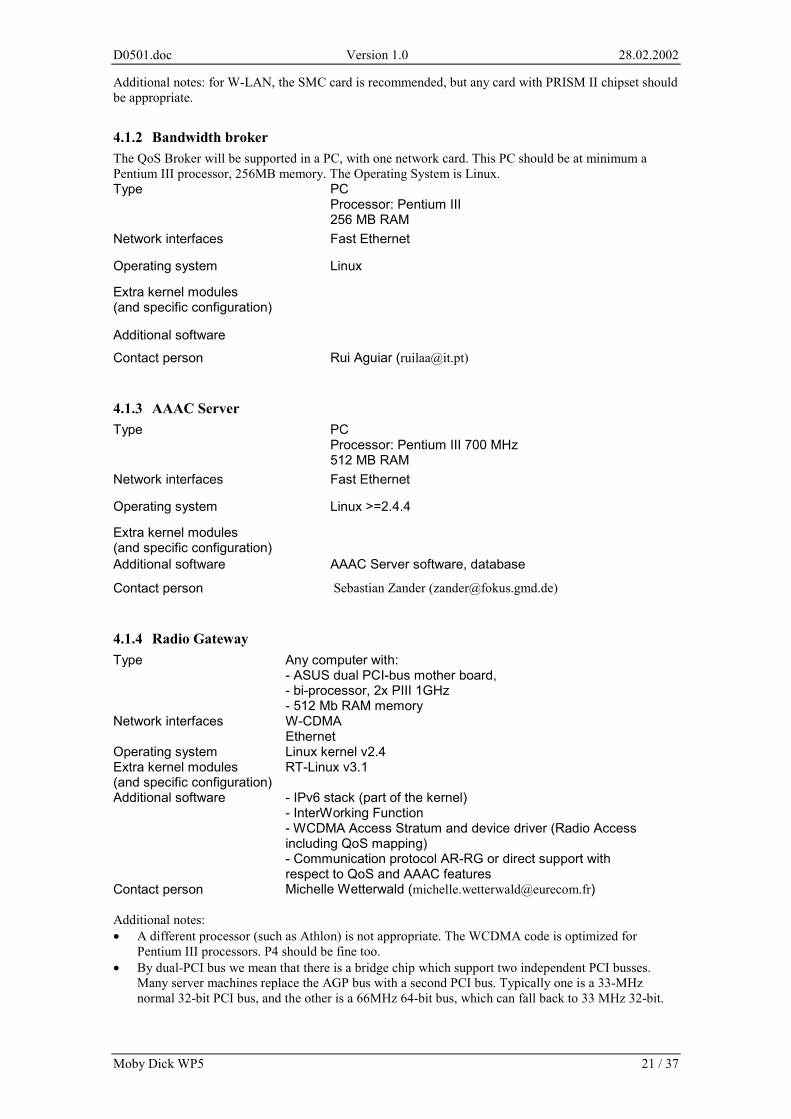
4.1.2 Bandwidth broker The QoS Broker will be supported in a PC, with one network card. This PC should be at minimum a Pentium III processor, 256MB memory. The Operating System is Linux. Type PC
Processor: Pentium III 256 MB RAM
Network interfaces Fast Ethernet
Operating system Linux
Extra kernel modules (and specific configuration)
Additional software
Contact person Rui Aguiar ([email protected])
4.1.3 AAAC Server Type PC
Processor: Pentium III 700 MHz 512 MB RAM
Network interfaces Fast Ethernet
Operating system Linux >=2.4.4
Extra kernel modules (and specific configuration)
Additional software AAAC Server software, database
Contact person Sebastian Zander ([email protected])
4.1.4 Radio Gateway Type Any computer with:
- ASUS dual PCI-bus mother board, - bi-processor, 2x PIII 1GHz - 512 Mb RAM memory
Network interfaces W-CDMA Ethernet
Operating system Linux kernel v2.4 Extra kernel modules (and specific configuration)
RT-Linux v3.1
Additional software - IPv6 stack (part of the kernel) - InterWorking Function - WCDMA Access Stratum and device driver (Radio Access including QoS mapping) - Communication protocol AR-RG or direct support with respect to QoS and AAAC features
Contact person Michelle Wetterwald ([email protected]) Additional notes: • A different processor (such as Athlon) is not appropriate. The WCDMA code is optimized for
Pentium III processors. P4 should be fine too. • By dual-PCI bus we mean that there is a bridge chip which support two independent PCI busses.
Many server machines replace the AGP bus with a second PCI bus. Typically one is a 33-MHz normal 32-bit PCI bus, and the other is a 66MHz 64-bit bus, which can fall back to 33 MHz 32-bit.
D0501.doc Version 1.0 28.02.2002
Moby Dick WP5 22 / 37
• The InterWorking Function, as defined in deliverable D0101, will perform the necessary mappings between the radio and IPv6 protocols:
- Packet forwarding support, - Paging awareness and mapping.
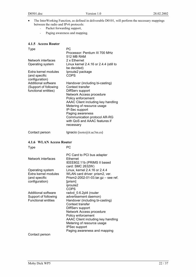
4.1.5 Access Router Type PC
Processor: Pentium III 700 MHz 512 MB RAM
Network interfaces 2 x Ethernet Operating system Linux kernel 2.4.16 or 2.4.4 (still to
be decided) Extra kernel modules (and specific configuration)
Iproute2 package COPS
Additional software (Support of following functional entities)
Handover (including bi-casting) Context transfer DiffServ support Network Access procedure Policy enforcement AAAC Client including key handling Metering of resource usage IP-Sec support Paging awareness Communication protocol AR-RG with QoS and AAAC features if necessary
Contact person Ignacio ([email protected])
4.1.6 WLAN Access Router Type PC
PC Card to PCI bus adapter
Network interfaces Ethernet IEEE802.11b (PRIMS II based card: SMC 2632W)
Operating system Linux, kernel 2.4.16 or 2.4.4 Extra kernel modules (and specific configuration)
WLAN card driver: prism2, ver. Prism2-2002-01-03.tar.gz – see ref. [prism] iproute2 COPS
Additional software Support of following Functional entities
radvd_0.6.2pl4 (router advertisement daemon) Handover (including bi-casting) Context transfer DiffServ support Network Access procedure Policy enforcement AAAC Client including key handling Metering of resource usage IPSec support Paging awareness and mapping
Contact person
D0501.doc Version 1.0 28.02.2002
Moby Dick WP5 23 / 37
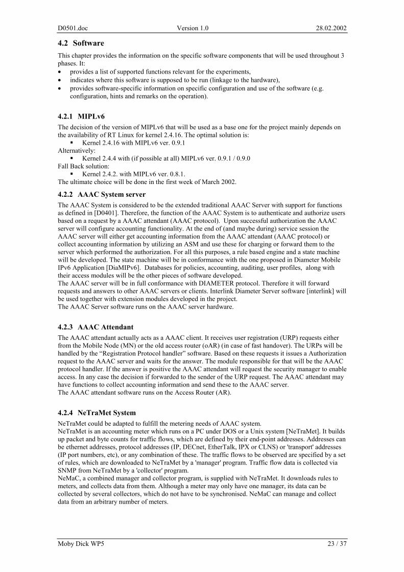
4.2 Software This chapter provides the information on the specific software components that will be used throughout 3 phases. It: • provides a list of supported functions relevant for the experiments, • indicates where this software is supposed to be run (linkage to the hardware), • provides software-specific information on specific configuration and use of the software (e.g.
configuration, hints and remarks on the operation).
4.2.1 MIPLv6 The decision of the version of MIPLv6 that will be used as a base one for the project mainly depends on the availability of RT Linux for kernel 2.4.16. The optimal solution is:
� Kernel 2.4.16 with MIPLv6 ver. 0.9.1 Alternatively:
� Kernel 2.4.4 with (if possible at all) MIPLv6 ver. 0.9.1 / 0.9.0 Fall Back solution:
� Kernel 2.4.2. with MIPLv6 ver. 0.8.1. The ultimate choice will be done in the first week of March 2002.
4.2.2 AAAC System server The AAAC System is considered to be the extended traditional AAAC Server with support for functions as defined in [D0401]. Therefore, the function of the AAAC System is to authenticate and authorize users based on a request by a AAAC attendant (AAAC protocol). Upon successful authorization the AAAC server will configure accounting functionality. At the end of (and maybe during) service session the AAAC server will either get accounting information from the AAAC attendant (AAAC protocol) or collect accounting information by utilizing an ASM and use these for charging or forward them to the server which performed the authorization. For all this purposes, a rule based engine and a state machine will be developed. The state machine will be in conformance with the one proposed in Diameter Mobile IPv6 Application [DiaMIPv6]. Databases for policies, accounting, auditing, user profiles, along with their access modules will be the other pieces of software developed. The AAAC server will be in full conformance with DIAMETER protocol. Therefore it will forward requests and answers to other AAAC servers or clients. Interlink Diameter Server software [interlink] will be used together with extension modules developed in the project. The AAAC Server software runs on the AAAC server hardware.
4.2.3 AAAC Attendant The AAAC attendant actually acts as a AAAC client. It receives user registration (URP) requests either from the Mobile Node (MN) or the old access router (oAR) (in case of fast handover). The URPs will be handled by the “Registration Protocol handler” software. Based on these requests it issues a Authorization request to the AAAC server and waits for the answer. The module responsible for that will be the AAAC protocol handler. If the answer is positive the AAAC attendant will request the security manager to enable access. In any case the decision if forwarded to the sender of the URP request. The AAAC attendant may have functions to collect accounting information and send these to the AAAC server. The AAAC attendant software runs on the Access Router (AR).
4.2.4 NeTraMet System NeTraMet could be adapted to fulfill the metering needs of AAAC system. NeTraMet is an accounting meter which runs on a PC under DOS or a Unix system [NeTraMet]. It builds up packet and byte counts for traffic flows, which are defined by their end-point addresses. Addresses can be ethernet addresses, protocol addresses (IP, DECnet, EtherTalk, IPX or CLNS) or 'transport' addresses (IP port numbers, etc), or any combination of these. The traffic flows to be observed are specified by a set of rules, which are downloaded to NeTraMet by a 'manager' program. Traffic flow data is collected via SNMP from NeTraMet by a 'collector' program. NeMaC, a combined manager and collector program, is supplied with NeTraMet. It downloads rules to meters, and collects data from them. Although a meter may only have one manager, its data can be collected by several collectors, which do not have to be synchronised. NeMaC can manage and collect data from an arbitrary number of meters.
D0501.doc Version 1.0 28.02.2002
Moby Dick WP5 24 / 37
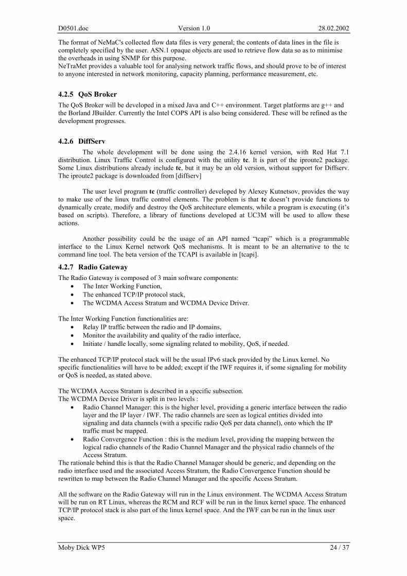
The format of NeMaC's collected flow data files is very general; the contents of data lines in the file is completely specified by the user. ASN.1 opaque objects are used to retrieve flow data so as to minimise the overheads in using SNMP for this purpose. NeTraMet provides a valuable tool for analysing network traffic flows, and should prove to be of interest to anyone interested in network monitoring, capacity planning, performance measurement, etc.
4.2.5 QoS Broker The QoS Broker will be developed in a mixed Java and C++ environment. Target platforms are g++ and the Borland JBuilder. Currently the Intel COPS API is also being considered. These will be refined as the development progresses.
4.2.6 DiffServ The whole development will be done using the 2.4.16 kernel version, with Red Hat 7.1
distribution. Linux Traffic Control is configured with the utility tc. It is part of the iproute2 package. Some Linux distributions already include tc, but it may be an old version, without support for Diffserv. The iproute2 package is downloaded from [diffserv]
The user level program tc (traffic controller) developed by Alexey Kutnetsov, provides the way
to make use of the linux traffic control elements. The problem is that tc doesn’t provide functions to dynamically create, modify and destroy the QoS architecture elements, while a program is executing (it’s based on scripts). Therefore, a library of functions developed at UC3M will be used to allow these actions.
Another possibility could be the usage of an API named “tcapi” which is a programmable
interface to the Linux Kernel network QoS mechanisms. It is meant to be an alternative to the tc command line tool. The beta version of the TCAPI is available in [tcapi].
4.2.7 Radio Gateway The Radio Gateway is composed of 3 main software components:
• The Inter Working Function, • The enhanced TCP/IP protocol stack, • The WCDMA Access Stratum and WCDMA Device Driver.
The Inter Working Function functionalities are:
• Relay IP traffic between the radio and IP domains, • Monitor the availability and quality of the radio interface, • Initiate / handle locally, some signaling related to mobility, QoS, if needed.
The enhanced TCP/IP protocol stack will be the usual IPv6 stack provided by the Linux kernel. No specific functionalities will have to be added; except if the IWF requires it, if some signaling for mobility or QoS is needed, as stated above. The WCDMA Access Stratum is described in a specific subsection. The WCDMA Device Driver is split in two levels :
• Radio Channel Manager: this is the higher level, providing a generic interface between the radio layer and the IP layer / IWF. The radio channels are seen as logical entities divided into signaling and data channels (with a specific radio QoS per data channel), onto which the IP traffic must be mapped.
• Radio Convergence Function : this is the medium level, providing the mapping between the logical radio channels of the Radio Channel Manager and the physical radio channels of the Access Stratum.
The rationale behind this is that the Radio Channel Manager should be generic, and depending on the radio interface used and the associated Access Stratum, the Radio Convergence Function should be rewritten to map between the Radio Channel Manager and the specific Access Stratum. All the software on the Radio Gateway will run in the Linux environment. The WCDMA Access Stratum will be run on RT Linux, whereas the RCM and RCF will be run in the linux kernel space. The enhanced TCP/IP protocol stack is also part of the linux kernel space. And the IWF can be run in the linux user space.
D0501.doc Version 1.0 28.02.2002
Moby Dick WP5 25 / 37
4.2.8 MT Middleware The Mobile Terminal middleware is composed of 4 main software components:
• The Networking Control Panel, • The Mobile Terminal Networking Manager, • The enhanced TCP/IP protocol stack, • The WCDMA Access Stratum and WCDMA Device Driver.
The Networking Control Panel functionalities are:
• Obtain user’s preferences related to network selection (Ethernet / WCDMA /W-LAN), • Obtain user’s preferences related to handover strategy (automatic / manual / both), • Trigger a manual handover, • Provide feedbacks and information on the networking environment for WCDMA and W-LAN.
The Mobile Terminal Networking Manager functionalities are:
• Handle user requests from the NCP regarding network selection, handover strategy, manual handover, feedbacks / information,
• Get information on the networking conditions from network drivers (Ethernet, WCDMA, W-LAN) to support the automatic handover decision making,
• Provide the automatic handover strategy with an algorithm based on user preferences and networking conditions,
• Initiate any signaling related to Mobility, AAAC, QoS with the enhanced TCP/IP protocol stack, to support handover execution,
• Initiate any reconfiguration of the enhanced TCP/IP protocol stack and network drivers (Ethernet, WCDMA, W-LAN) to support handover execution.
The enhanced TCP/IP protocol stack will be the usual IPv6 stack provided by the Linux kernel, enhanced by the MIPL patch for mobility management and any specific features needed to support QoS and AAAC. The WCDMA Access Stratum is described in a specific subsection. The WCDMA Device Driver is split in two levels :
• Radio Channel Manager, • Radio Convergence Function,
The general description of the WCDMA AS, RCM and RCF is the same as for the Radio Gateway, but the detailed functionalities of these will be different on the Mobile Terminal and on the Radio Gateway. All the software on the Mobile Terminal will run in the Linux environment. The WCDMA Access Stratum will be run on RT Linux, whereas the RCM and RCF will be run in the linux kernel space. The enhanced TCP/IP protocol stack is also part of the linux kernel space. And the NCP and MTNM can be run in the linux user space.
4.2.9 WCDMA Access Stratum The WCDMA Access Stratum is part of the WCDMA platform. A major feature of this platform is that besides the RF functions that are implemented in hardware (cf Radio Gateway and Mobile Terminal), all the protocol layers, from physical to networking, are implemented in software. They are in a module of the linux operating system, under the control of RTLinux, an open-source hard real-time operating system. The Access Stratum Protocol Layers planned for this project contain:
- Layers 1 (PHY) and 2 (MAC/RLC/PDCP) according to 3GPP specification, - Radio Resource Control (RRC) based on 3GPP, but accommodating Moby Dick framework.
Two complementary versions are available, one for the Mobile Terminal, one for the Radio Gateway, supporting several WCDMA Mobile Terminals. The Access Stratum interfaces its driver and the Non Access Stratum functions by the means of RT-FIFOS. They are allocated in the kernel address space during the initialization of the module and are seen as ordinary character devices from Linux user and kernel processes.
D0501.doc Version 1.0 28.02.2002
Moby Dick WP5 26 / 37
4.3 Other software tools
4.3.1 CVS CVS is the Concurrent Versions System [CVS1], the dominant open-source network-transparent version control system. It is in wide use around the world, including many free software projects. Using CVS, the history of sources files and documents will be recorded. It offers the following significant advantages [CVS2]: • Client/server CVS enables developers scattered by geography to function as a single team. The
version history is stored on a single central server and the client machines have a copy of all the files that the developers are working on. Clients can perform all the same operations which are available locally.
• CVS basic version control functionality maintains a history of all changes made to each directory tree it manages, operating on entire directory trees, not just single files.
• CVS can handle any binary format, in addition to source files. • In cases where several developers or teams want to each maintain their own version of the files,
because of geography and/or policy, CVS's vendor branches can import a version from another team (even if they don't use CVS), and then CVS can merge the changes from the vendor branch with the latest files if that is what is desired.
• CVS can tag the state of the directory tree at a given point, recreate that state and display the differences between tags or revisions in the standard diff formats.
• CVS runs scripts which you supply to log operations or enforce site-specific policies. • CVS has unreserved checkouts, allowing more than one developer to work on the same files at the
same time and avoiding artificial conflicts common with the exclusive check-out model. • The configuration files allow CVS to interface to external bug tracking systems. • CVS provides reliable repository access to remote hosts using Internet protocols, facilitating
collaboration with distant employees and contractors. • Its client tools are available on most platforms. Storing the Moby Dick data in a CVS server rather than in a standard server will allow for flexible and safe handling of the pieces of code that will be delivered by the various partners and the tracking of the several phases of the Field Trial in a productive way.
4.3.2 Tests tools The following additional test tools will be used:
• Protocol analysers: different pieces of software capable of monitoring and analysing W-CDMA in the RAN, 802.11 and 802.3, the equipment for monitoring and analysing the UMTS forum signalling specifications.
• Traffic generator: Stand-alone equipment or Unix or Windows workstation running software
tool that provides the capability to generate IP traffic following a specific pattern (available tools are netperf , ttcp, mgen and others [RFC2398]).
4.4 Applications This section includes a list of IPv6 applications to be used in the trials. A detailed description is provided in [D0102]. The applications will include:
� Asynchronous Applications (non-real time): o Web based, o DB access, o E-mail, o File transfer, o Remote access (telnet, ssh), o Others.
� Synchronous Applications (real time):
o VoIP, o Teleconference,
D0501.doc Version 1.0 28.02.2002
Moby Dick WP5 27 / 37
o Teleteaching, o Others.
The above set of asynchronous applications represents a large group of elastic applications that contribute a substantial portion of traffic in Internet. Synchronous applications such as voice service have been selected as a validator due to the stringent requirements they impose on the performance of the network in terms of packet loss and packet delay. Both types of applications constitute a representative set of applications used today and are likely to be used in Internet also in the future.
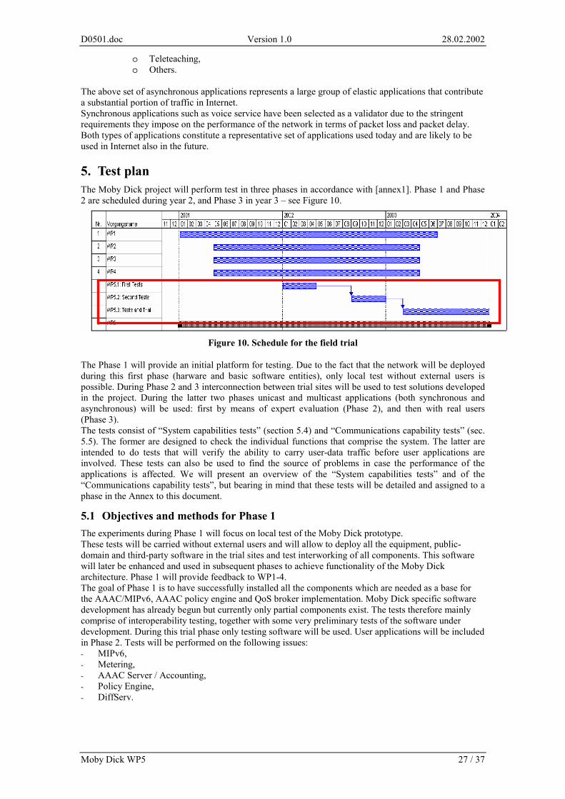
5. Test plan The Moby Dick project will perform test in three phases in accordance with [annex1]. Phase 1 and Phase 2 are scheduled during year 2, and Phase 3 in year 3 – see Figure 10.
Figure 10. Schedule for the field trial
The Phase 1 will provide an initial platform for testing. Due to the fact that the network will be deployed during this first phase (harware and basic software entities), only local test without external users is possible. During Phase 2 and 3 interconnection between trial sites will be used to test solutions developed in the project. During the latter two phases unicast and multicast applications (both synchronous and asynchronous) will be used: first by means of expert evaluation (Phase 2), and then with real users (Phase 3). The tests consist of “System capabilities tests” (section 5.4) and “Communications capability tests” (sec. 5.5). The former are designed to check the individual functions that comprise the system. The latter are intended to do tests that will verify the ability to carry user-data traffic before user applications are involved. These tests can also be used to find the source of problems in case the performance of the applications is affected. We will present an overview of the “System capabilities tests” and of the “Communications capability tests”, but bearing in mind that these tests will be detailed and assigned to a phase in the Annex to this document.
5.1 Objectives and methods for Phase 1 The experiments during Phase 1 will focus on local test of the Moby Dick prototype. These tests will be carried without external users and will allow to deploy all the equipment, public-domain and third-party software in the trial sites and test interworking of all components. This software will later be enhanced and used in subsequent phases to achieve functionality of the Moby Dick architecture. Phase 1 will provide feedback to WP1-4. The goal of Phase 1 is to have successfully installed all the components which are needed as a base for the AAAC/MIPv6, AAAC policy engine and QoS broker implementation. Moby Dick specific software development has already begun but currently only partial components exist. The tests therefore mainly comprise of interoperability testing, together with some very preliminary tests of the software under development. During this trial phase only testing software will be used. User applications will be included in Phase 2. Tests will be performed on the following issues: - MIPv6, - Metering, - AAAC Server / Accounting, - Policy Engine, - DiffServ.
D0501.doc Version 1.0 28.02.2002
Moby Dick WP5 28 / 37
5.2 Objectives and methods for Phase 2 The goal of Phase 2 is to test the implementation of AAAC/MIPv6, AAAC policy engine and QoS Broker and check interworking between themselves and with other relevant components of the distributed system developed in the project. The tests will be carried first with use of testing software and then with user applications. The majority of changes, bug identification and fixing are expected to take place during this phase. In contrast to Phase 3 only test configurations are used here (i.e. experimental user profiles and test policies).
5.3 Objectives and methods for Phase 3 The aim of this phase is to test the integrity and stability of the system by means of expert evaluation, and then to subject the system to tests with real users in real environment. The users will exercise the system by subscribing to services, attaching to the network during their stay in home or in a visited domain and invoking services. The tests to be carried involve tests of Phase 2. However, during tests with real users the emphasis will be on human factors, in order to learn the user’s perception of the system. This is further explained in chapter 6.3.
5.4 System capabilities tests System capabilities tests is a set of tests intended to check the individual functions that comprise the system. These tests will verify that given functions are present in the field trial and that their behaviour conforms to the expectations of the system designers. Some of them are relatively low-level and refer to a certain interaction such as, for example, a single step of the handover procedure. Others refer to more complex interactions and test, for example, the procedures or processes that involve complex interaction between components. All the tests are given with a brief statements of expected behaviour.
5.4.1 IPv6 on fixed-network nodes All the network nodes in the fixed network can reach each-other. This shows that MIPL protocol stack is running and configured with valid IPv6 address via stateless address configuration. A valid IPv6 addresses must adhere to the addressing plan given in sections 3.1 and 3.2.
5.4.2 MIPv6 on Mobile Node The following tests are performed regarding MN behaviour in a foreign network: 1. MN correctly discovers a new AR, 2. MN correctly configures its CoA using IPv6 Stateless Address Configuration. (64 bit Network Prefix
+ 64 bit EUI), 3. MN updates its routing tables (default route through the AR), 4. MN sends the (home) BU to its HA updating its CoA, 5. MN receives the BACK from its HA, 6. MN sets up the tunnel with the HA. The following tests are performed regarding AR behaviour: 1. AR correctly advertises its network prefix. The following tests are performed regarding HA behaviour: 1. HA receives/processes a BU from a MN, 2. HA performs proxy Neighbor Discovery for the home address of the MN, 3. HA tears down the tunnel to the old CoA, 4. HA sets up the tunnel to the new CoA, 5. HA sends a BACK to the MN.
5.4.3 Fast Handover The MN moves from one AR to another AR in the same domain. The following tests are performed regarding the MN: 1. MN detects another AR with a stronger radio signal (the method for this is for further study) 2. MN sends an RtSolPr to the old AR, 3. MN receives PrRtAdv; process it in order to construct the new COA, 4. MN sends an FBU to the old AR,
D0501.doc Version 1.0 28.02.2002
Moby Dick WP5 29 / 37
5. Upon receiving FBACK the MN connects to the new AR, 6. MN sends an FNA message to the new AR. Note: 2,3,4,5,6 may be optional when a network triggered hand-off is considered (this scenario is to be defined in more detail upon final agreement on Fast Handover+AAAC scheme.) The following tests are performed regarding the AR: 1. oAR has to include an [AAAC option] into the HI message, 2. nAR processes the [AAAC option] sets up its routing tables/network filters accordingly, that is
granting access to the network to the MN; it also issues an HACK to the oAR. The following test are performed regarding the AAAC.f: 1. The AAAC.f verifies that it already an ongoing session for the user and that a subset of the profile is
present, 2. Upon receiving a AA_Request_Message the user is authorized according to the request, user profile
subset and authorization policies, 3. An AA_Response_Message is sent back to the AR containing the authorization status and in case of
successful authorisation configuration information like keys for MN, AR, user profile subset, accounting policies etc.
5.4.4 Registration The MN boots in a foreign domain. The following tests are performed regarding the MN: 1. MN correctly discovers the AR in the foreign network, 2. MN sends an AA_Request_Message (ICMPv6 packet) to the AR, 3. MN correctly processes an AA_Response_Message received from AR, 4. when the AA_Response_Message contained no error codes denying access, the MN sets up its
routing tables accordingly (i.e. using AR as default router) and starts sending/receiving IP packets, 5. if the MIPv6 BU was not piggybacked into the AAAC signaling messages, the MN will start the
MIPv6 (home) registration procedure. The following test are performed regarding the AR: 1. AR does not forward/route any packet coming on any of its interfaces from an
unauthenticated/unauthorized source (MN), 2. AR accepts and processes ICMPv6 messages containing an AA_Request_Message. 3. AR constructs (from the AA_Request_Message received from the MN) and sends DIAMETER AA
registration request to the AAAC.f, 4. when the AR receives an AA_Response_Message containing no error codes sends an AA response
message to the MN and sets up its routing tables/network filters accordingly that is granting access to the network to the MN,
5. when the AA response message contains error codes the AR will send an AA response message to the MN saying its access was denied.
The following test are performed regarding the AAAC.f: 1. Upon receiving a AA_Request_Message the message is forwarded to the correct AAAC.h, 2. Upon receiving an AA_Response_Message from the AAAC.h the AAAC.f forwards it to the AR. The following test are performed regarding the AAAC.h: 1. Upon receiving a AA_Request_Message the user is authenticated according to the identity and
credentials provided and the authentication policies and the user is authorized according to the request, user profile and authorization policies,
2. An AA_Response_Message is sent back to the AAAC.f containing the authorization status and in case of successful authorization configuration information like keys for MN, AR, user profile subset, accounting policies etc.
5.4.5 AAAC Server / Authorization After the Interlink Software is being configured on AAAC server and client, sample policies have to be developed to test the functionality. Probably only NAS and mobility functionality will be tested, no QoS. At this time, no database is needed. The meters must be up and running on AAAC client, eventually AAAC server. User authentication could be done using different mechanism. An integrated rule based engine is not needed for phase 1, no ASM’s. Test Scenario: 1. A user attempts to use the NAS,
D0501.doc Version 1.0 28.02.2002
Moby Dick WP5 30 / 37
2. The credentials are sent by AAAC client to AAAC server, 3. Based on policies access is granted or denied,
5.4.6 Policy Engine The policy engine is tested with a test client which generates AA request. The following test are performed: 1. Authentication policies based on user profile, 2. Authorization policies based on user profile and other factors (e.g. time of day etc.), 3. Accounting policies based on service and user profile.
5.4.7 Metering After meter and meter manager/reader have been installed and configured, a test set of rules will be created for metering traffic from a traffic generation tool. The output of the meter reader must be compared to the traffic generator parameter to verify that metering of service usage works correctly.
5.4.8 Accounting We assume here that authentication and authorization have been successful completed. Scenario 1: Standard behaviour 1. Based on MN identity and AAAC.h response the correct accounting policy is selected by AAAC.f, 2. The policy is evaluated by the Rule Based Engine yielding an action, 3. The accounting is translated into a metering policy, 4. In the visited network the meters are configured protocol, 5. AAAC application gathers accounting records from all involved nodes, 6. If the session lifetime expires interim records are generated, 7. When the session ends, the accounting records are stored in the database for further processing, 8. Accounting records are send back to the AAAC.h. Scenario 2: Fast Handover, MN has connectivity to nAR and oAR at the same time (nAR and oAR belong to the same AD) 1. Accounting is running for oAR, 2. MN discovers nAR while still connected to oAR, 3. During fast handover accounting starts for nAR, 4. For the transition period, metering data is generated by both oAR and nAR, 5. AAAC context is transferred from oAR to nAR, 6. AAAC server maps the different metering data record sets into one accounting record set, 7. Accounting record is stored in database when connection is finished.
5.4.9 AAAC System and QoS Interaction AAAC and QoS interact at session setup and at session termination. Interaction between AAAC and QoS is performed solely between AAAC system server-side and QoS Broker. The aim is to test the ASM that makes this interaction possible, not to test the working of the AAAC system nor the one of the QoS Broker. At session setup, whether the user gets QoS session depends on Authentication and Authorization (AA) and the availability of resources in the network. Requirements (starting conditions):
1. Authentication has already been done and AAAC.f has the needed subset of the user profile. 2. The authorization request (or end of session request) has already been forwarded to the AAAC.f.
This authorization request has all the data needed to by the API functions of the ASM. Note: If the user is in his home domain, there is no AAAC.f involved but simply the AAAC.h. Tests: 1. AAAC server source code calls the API function checkAvailability(). This triggers a valid COPS
message sent to the QoS broker. The DEC message is received containing the needed parameters. checkAvailability() should then return these parameters.
2. AAAC server source code calls the API function QoSReservation(). This triggers a valid COPS message sent to the QoS broker with all the parameters set in QoSReservation(). The DEC message is
D0501.doc Version 1.0 28.02.2002
Moby Dick WP5 31 / 37
received indicating success or failure (and the reason). QoSReservation() should then return with the appropriate error code (0 if success).
3. AAAC server source code calls the API function releaseQoS().This triggers a valid COPS message sent to the QoS broker. The DEC message is received. releaseQoS() should then return.
5.4.10 Resource allocation Objective: to check that the QoS Broker sends resource allocation requests to the AR. Requirements (starting conditions): see section 5.4.9. Tests: 1. MT sends data with a DSCP indicating the QoS service to be applied. Verify that the MT
Middleware identifies the packet, triggers the resource allocation in the RG and AR via AAAC and that the resources are allocated (for eligible resource request), or a denial of service is issued for unauthorised service.
2. MT sends the reservation release. Verify that the resources are released.
5.5 Communications capability tests In order to take an overview of the different communications capability tests, we will list the possible factors to be taken into account. It should be noted first that the definitions are unidirectional. Since some protocols use acknowledge mechanisms, there will be backward traffic that should be also taken into account. For this reason a TCP flow requires identification of the flow and two reservations in the AR triggered when the packets traverse the node. The experiments defined in this chapter will take into account the following factors: number of destinations, location of the source or destination in the network, access technology, mobility and traffic. Number of destinations. Since some of the applications (videoconference, video on demand,…) have inherent multicast nature, the tests should evaluate the ability of the network to support such applications. Possible values: 1..n . Location of the traffic source or sink in the network. The actions taken by the system to maintain a traffic flow and the network elements that will be invoked will depend on the location of the source and sink in the network. These can be in the core network, in other operator’s fixed network or in the access network. The idea is to identify different administrative domains, testing the intercommunication among them. This dimension is clearly related to mobility, as it will be seen later. Possible values: Both in the same administrative domain, in different domains of the same network provider, in networks of different providers. Access Technology. There will be three different access technologies. While the foregoing paragraph was related to network administration and policies, this section is concerned about the availability to user layer-2-dependant features. Possible values: WLAN, Ethernet, WCDMA. Mobility. It should be considered what level of mobility a user is allowed for in each of the trials. Mobility depends not only on the availability of the access technology, but also on the location of a user in the network. For example a user may have a choice of one of three available technologies but only in its home network; but only two of them when in visited domain. Possible values: no mobility, mobility within selected technology of any network provider, different technologies of the same provider… Traffic profiles. Different traffic classes as well as different parameters and QoS assurance may be specified for users depending on their needs. This will result in numerous traffic profiles. for tests in order to test the support for QoS. Depending on the number of classes and parameters more or less trials should be performed, in order to evaluate a network carrying a traffic of a representative set of applications. Depending on the different QoS profiles defined various traffic profiles should be tested to increase the level of confidence that the network will exhibit correct behaviour for any profile. Possible values: “best effort”, “interactive”, “streaming” etc. In this section basic transmission tests are defined, grouped by common objectives and sorted by complexity. All connections may request certain quality of service by invoking eligible service class. Each connection is considered as unidirectional.
5.5.1 Reachability In order to test the network operation this test can be considered as the most simple but essential. With it, the ability to set-up data channels and the bi-directional communications at the IP layer can be tested.
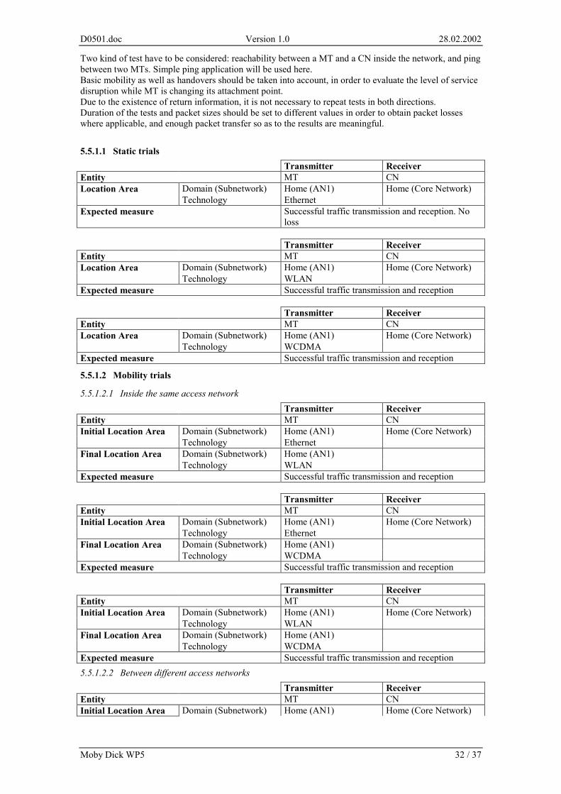
D0501.doc Version 1.0 28.02.2002
Moby Dick WP5 32 / 37
Two kind of test have to be considered: reachability between a MT and a CN inside the network, and ping between two MTs. Simple ping application will be used here. Basic mobility as well as handovers should be taken into account, in order to evaluate the level of service disruption while MT is changing its attachment point. Due to the existence of return information, it is not necessary to repeat tests in both directions. Duration of the tests and packet sizes should be set to different values in order to obtain packet losses where applicable, and enough packet transfer so as to the results are meaningful.
5.5.1.1 Static trials Transmitter Receiver Entity MT CN
Domain (Subnetwork) Home (AN1) Home (Core Network) Location Area Technology Ethernet
Expected measure Successful traffic transmission and reception. No loss
Transmitter Receiver Entity MT CN
Domain (Subnetwork) Home (AN1) Home (Core Network) Location Area Technology WLAN
Expected measure Successful traffic transmission and reception Transmitter Receiver Entity MT CN
Domain (Subnetwork) Home (AN1) Home (Core Network) Location Area Technology WCDMA
Expected measure Successful traffic transmission and reception
5.5.1.2 Mobility trials
5.5.1.2.1 Inside the same access network Transmitter Receiver Entity MT CN
Domain (Subnetwork) Home (AN1) Home (Core Network) Initial Location Area Technology Ethernet Domain (Subnetwork) Home (AN1) Final Location Area Technology WLAN
Expected measure Successful traffic transmission and reception Transmitter Receiver Entity MT CN
Domain (Subnetwork) Home (AN1) Home (Core Network) Initial Location Area Technology Ethernet Domain (Subnetwork) Home (AN1) Final Location Area Technology WCDMA
Expected measure Successful traffic transmission and reception Transmitter Receiver Entity MT CN
Domain (Subnetwork) Home (AN1) Home (Core Network) Initial Location Area Technology WLAN Domain (Subnetwork) Home (AN1) Final Location Area Technology WCDMA
Expected measure Successful traffic transmission and reception 5.5.1.2.2 Between different access networks Transmitter Receiver Entity MT CN Initial Location Area Domain (Subnetwork) Home (AN1) Home (Core Network)
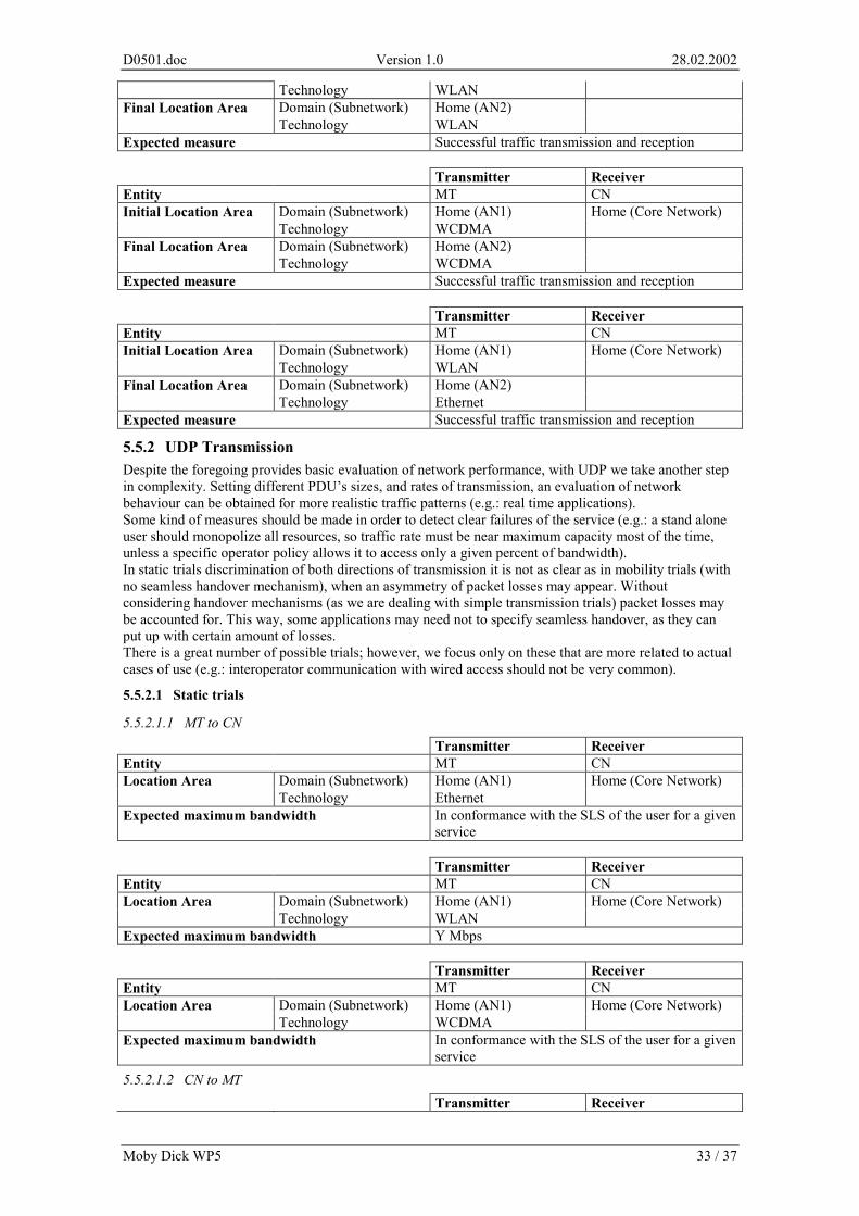
D0501.doc Version 1.0 28.02.2002
Moby Dick WP5 33 / 37
Technology WLAN Domain (Subnetwork) Home (AN2) Final Location Area Technology WLAN
Expected measure Successful traffic transmission and reception Transmitter Receiver Entity MT CN
Domain (Subnetwork) Home (AN1) Home (Core Network) Initial Location Area Technology WCDMA Domain (Subnetwork) Home (AN2) Final Location Area Technology WCDMA
Expected measure Successful traffic transmission and reception Transmitter Receiver Entity MT CN
Domain (Subnetwork) Home (AN1) Home (Core Network) Initial Location Area Technology WLAN Domain (Subnetwork) Home (AN2) Final Location Area Technology Ethernet
Expected measure Successful traffic transmission and reception
5.5.2 UDP Transmission Despite the foregoing provides basic evaluation of network performance, with UDP we take another step in complexity. Setting different PDU’s sizes, and rates of transmission, an evaluation of network behaviour can be obtained for more realistic traffic patterns (e.g.: real time applications). Some kind of measures should be made in order to detect clear failures of the service (e.g.: a stand alone user should monopolize all resources, so traffic rate must be near maximum capacity most of the time, unless a specific operator policy allows it to access only a given percent of bandwidth). In static trials discrimination of both directions of transmission it is not as clear as in mobility trials (with no seamless handover mechanism), when an asymmetry of packet losses may appear. Without considering handover mechanisms (as we are dealing with simple transmission trials) packet losses may be accounted for. This way, some applications may need not to specify seamless handover, as they can put up with certain amount of losses. There is a great number of possible trials; however, we focus only on these that are more related to actual cases of use (e.g.: interoperator communication with wired access should not be very common).
5.5.2.1 Static trials
5.5.2.1.1 MT to CN Transmitter Receiver Entity MT CN
Domain (Subnetwork) Home (AN1) Home (Core Network) Location Area Technology Ethernet
Expected maximum bandwidth In conformance with the SLS of the user for a given service
Transmitter Receiver Entity MT CN
Domain (Subnetwork) Home (AN1) Home (Core Network) Location Area Technology WLAN
Expected maximum bandwidth Y Mbps Transmitter Receiver Entity MT CN
Domain (Subnetwork) Home (AN1) Home (Core Network) Location Area Technology WCDMA
Expected maximum bandwidth In conformance with the SLS of the user for a given service
5.5.2.1.2 CN to MT Transmitter Receiver
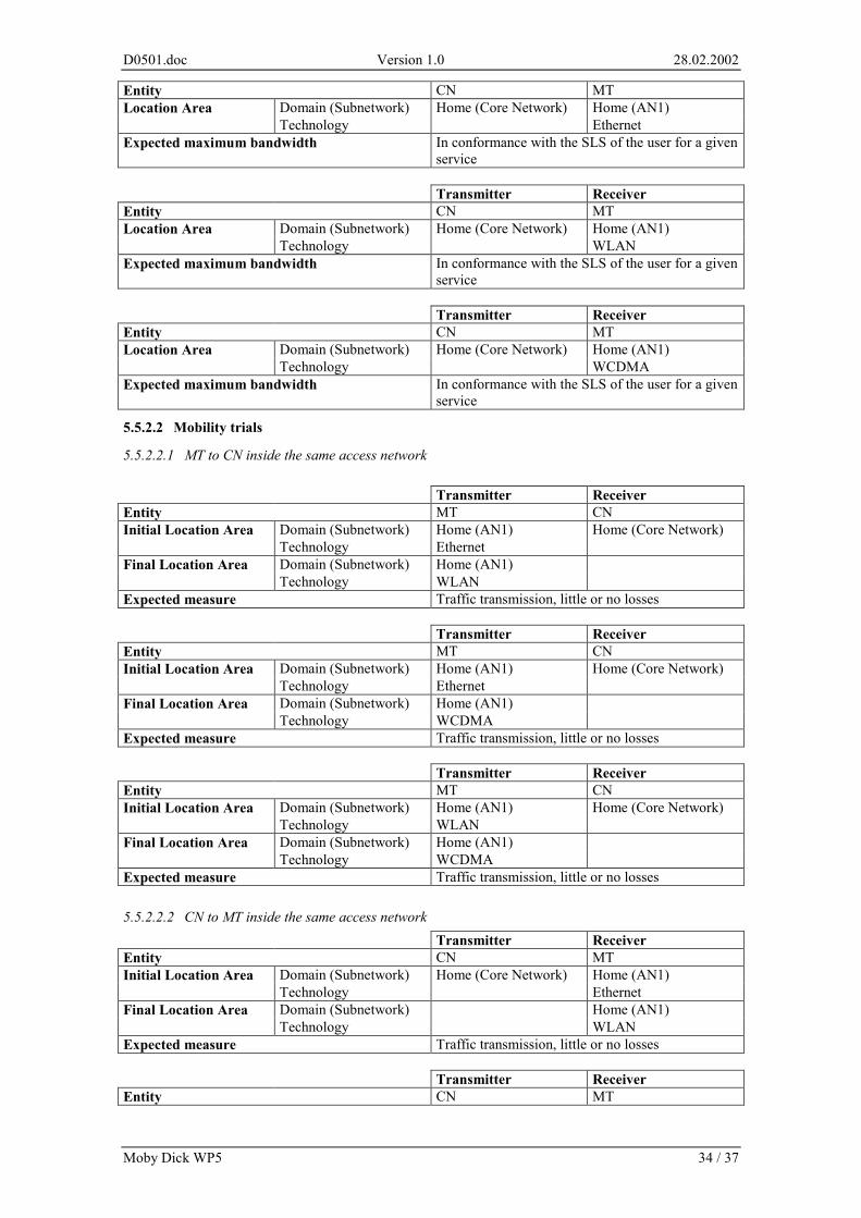
D0501.doc Version 1.0 28.02.2002
Moby Dick WP5 34 / 37
Entity CN MT Domain (Subnetwork) Home (Core Network) Home (AN1) Location Area Technology Ethernet
Expected maximum bandwidth In conformance with the SLS of the user for a given service
Transmitter Receiver Entity CN MT
Domain (Subnetwork) Home (Core Network) Home (AN1) Location Area Technology WLAN
Expected maximum bandwidth In conformance with the SLS of the user for a given service
Transmitter Receiver Entity CN MT
Domain (Subnetwork) Home (Core Network) Home (AN1) Location Area Technology WCDMA
Expected maximum bandwidth In conformance with the SLS of the user for a given service
5.5.2.2 Mobility trials
5.5.2.2.1 MT to CN inside the same access network Transmitter Receiver Entity MT CN
Domain (Subnetwork) Home (AN1) Home (Core Network) Initial Location Area Technology Ethernet Domain (Subnetwork) Home (AN1) Final Location Area Technology WLAN
Expected measure Traffic transmission, little or no losses Transmitter Receiver Entity MT CN
Domain (Subnetwork) Home (AN1) Home (Core Network) Initial Location Area Technology Ethernet Domain (Subnetwork) Home (AN1) Final Location Area Technology WCDMA
Expected measure Traffic transmission, little or no losses Transmitter Receiver Entity MT CN
Domain (Subnetwork) Home (AN1) Home (Core Network) Initial Location Area Technology WLAN Domain (Subnetwork) Home (AN1) Final Location Area Technology WCDMA
Expected measure Traffic transmission, little or no losses 5.5.2.2.2 CN to MT inside the same access network Transmitter Receiver Entity CN MT
Domain (Subnetwork) Home (Core Network) Home (AN1) Initial Location Area Technology Ethernet Domain (Subnetwork) Home (AN1) Final Location Area Technology WLAN
Expected measure Traffic transmission, little or no losses Transmitter Receiver Entity CN MT
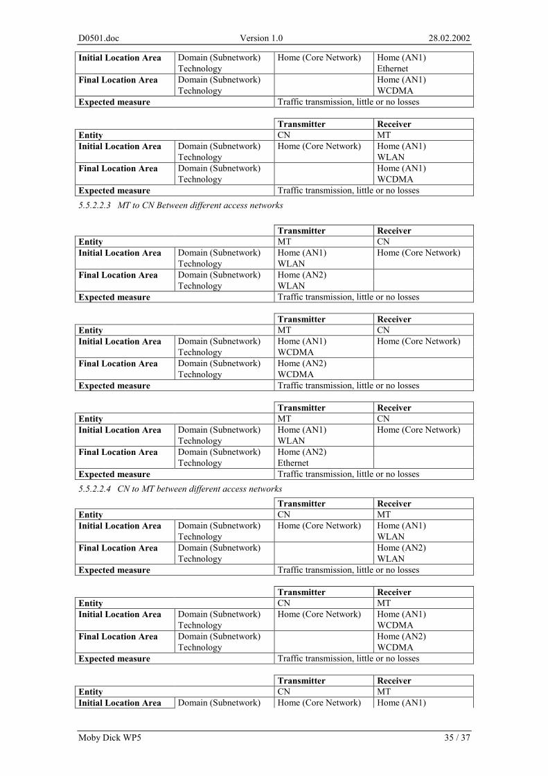
D0501.doc Version 1.0 28.02.2002
Moby Dick WP5 35 / 37
Domain (Subnetwork) Home (Core Network) Home (AN1) Initial Location Area Technology Ethernet Domain (Subnetwork) Home (AN1) Final Location Area Technology WCDMA
Expected measure Traffic transmission, little or no losses Transmitter Receiver Entity CN MT
Domain (Subnetwork) Home (Core Network) Home (AN1) Initial Location Area Technology WLAN Domain (Subnetwork) Home (AN1) Final Location Area Technology WCDMA
Expected measure Traffic transmission, little or no losses 5.5.2.2.3 MT to CN Between different access networks Transmitter Receiver Entity MT CN
Domain (Subnetwork) Home (AN1) Home (Core Network) Initial Location Area Technology WLAN Domain (Subnetwork) Home (AN2) Final Location Area Technology WLAN
Expected measure Traffic transmission, little or no losses Transmitter Receiver Entity MT CN
Domain (Subnetwork) Home (AN1) Home (Core Network) Initial Location Area Technology WCDMA Domain (Subnetwork) Home (AN2) Final Location Area Technology WCDMA
Expected measure Traffic transmission, little or no losses Transmitter Receiver Entity MT CN
Domain (Subnetwork) Home (AN1) Home (Core Network) Initial Location Area Technology WLAN Domain (Subnetwork) Home (AN2) Final Location Area Technology Ethernet
Expected measure Traffic transmission, little or no losses 5.5.2.2.4 CN to MT between different access networks Transmitter Receiver Entity CN MT
Domain (Subnetwork) Home (Core Network) Home (AN1) Initial Location Area Technology WLAN Domain (Subnetwork) Home (AN2) Final Location Area Technology WLAN
Expected measure Traffic transmission, little or no losses Transmitter Receiver Entity CN MT
Domain (Subnetwork) Home (Core Network) Home (AN1) Initial Location Area Technology WCDMA Domain (Subnetwork) Home (AN2) Final Location Area Technology WCDMA
Expected measure Traffic transmission, little or no losses Transmitter Receiver Entity CN MT Initial Location Area Domain (Subnetwork) Home (Core Network) Home (AN1)
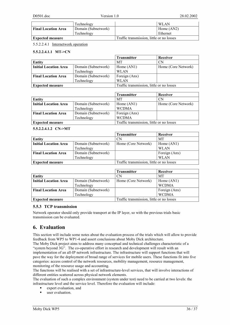
D0501.doc Version 1.0 28.02.2002
Moby Dick WP5 36 / 37
Technology WLAN Domain (Subnetwork) Home (AN2) Final Location Area Technology Ethernet
Expected measure Traffic transmission, little or no losses 5.5.2.2.4.1 Internetwork operation
5.5.2.2.4.1.1 MT->CN Transmitter Receiver Entity MT CN
Domain (Subnetwork) Home (AN1) Home (Core Network) Initial Location Area Technology WLAN Domain (Subnetwork) Foreign (Anx) Final Location Area Technology WLAN
Expected measure Traffic transmission, little or no losses Transmitter Receiver Entity MT CN
Domain (Subnetwork) Home (AN1) Home (Core Network) Initial Location Area Technology WCDMA Domain (Subnetwork) Foreign (Anx) Final Location Area Technology WCDMA
Expected measure Traffic transmission, little or no losses 5.5.2.2.4.1.2 CN->MT Transmitter Receiver Entity CN MT
Domain (Subnetwork) Home (Core Network) Home (AN1) Initial Location Area Technology WLAN Domain (Subnetwork) Foreign (Anx) Final Location Area Technology WLAN
Expected measure Traffic transmission, little or no losses Transmitter Receiver Entity CN MT
Domain (Subnetwork) Home (Core Network) Home (AN1) Initial Location Area Technology WCDMA Domain (Subnetwork) Foreign (Anx) Final Location Area Technology WCDMA
Expected measure Traffic transmission, little or no losses
5.5.3 TCP transmission Network operator should only provide transport at the IP layer, so with the previous trials basic transmission can be evaluated.
6. Evaluation This section will include some notes about the evaluation process of the trials which will allow to provide feedback from WP5 to WP1-4 and assert conclusions about Moby Dick architecture. The Moby Dick project aims to address many conceptual and technical challenges characteristic of a “system beyond 3G”. The co-operative effort in research and development will result with an implementation of an all-IP network infrastructure. The infrastructure will support functions that will pave the way for the deployment of broad range of services for mobile users. These functions fit into five categories: access control of the network resources, mobility management, resource management, monitoring of the resource usage and accounting. The functions will be realised with a set of infrastructure-level services, that will involve interactions of different entities scattered across physical network elements. The evaluation of such a complex environment (system under test) need to be carried at two levels: the infrastructure level and the service level. Therefore the evaluation will include:
� expert evaluation, and � user evaluation.
D0501.doc Version 1.0 28.02.2002
Moby Dick WP5 37 / 37
The expert evaluation will be carried with two different approaches: with simulation and in the field-trial. The user evaluation will involve real users (Erasmus students) that will use two types of applications within the area covered by the network infrastructure.
6.1 Expert evaluation in field trial In the field-trial trial the network infrastructure will be exposed to intensive testing evaluating the original design principles. Here, the functionality of the system will be checked against the requirements for the architecture that were defined in respective workpackages: WP2 (QoS), WP3 (mobility) and WP4 (AAAC), and then converted into the requirements of the field trial (sections 2.1, 2.2, 2.3). These test will first concentrate on workpackage specific requirements. Afterwards, the requirements of WP1 [D0101] will enable a cross-check and verification of the interworking of the features. The expert evaluation will also include the evaluation of the integrity and stability of the system. This kind of evaluation will be based on qualitative measures. The causes of incorrect operation, if any, will be identified and sent back to implementation teams.
6.2 Expert evaluation in simulation The are several aspects of the network design that can not be fully evaluated in the field-trial and call for other means of validation. This refers to features that will not be implemented due to manpower or time constraints. There also exist some features, that will be available in the field-trial, but can not be evaluated in full extent due to the size of the trial. An example of such features are some performance issues that need quantitative measures, e.g. latencies during the HO, signaling activity of the terminals and the resulting signaling load on the network, etc. For these cases, the simulations are considered as another means of validating the network design. They will be carried on in workpackages (WP2, WP3). The results will provide an idea of the relative changes in performance (or trends) as a function of the terms that affect the system.
6.3 User evaluation A part of the work of evaluating the network infrastructure will be carried with expert evaluation, i.e. without the participation of end users. This will be during Phase 1 and Phase 2 of the field-trial. However, the performance of the network has a substantial impact on the subjective perception and assessment of services offered by the infrastructure. Test Phase 3 will involve Erasmus students into the evaluation. The overall objective of this phase will be to take the evaluation of network technology to the user level to get qualitative feedback, evaluate user’s attitude and their interaction with the infrastructure. The observation will shed the light on user’s perception of the level of freedom they get with mobility and new features, e.g. QoS enhancements. It is also important to learn how the users understand, use and appreciate the features. It is expected that the users have little idea about the underlying technical issues and are not willing to modify their behaviour to the network-oriented way of thinking. These tests will show whether the level of transparency of underlying complexities is sufficient. The evaluation will be based on think-aloud sessions and focus group discussions. The former one will provide feedback about how the users interact with the applications and network, and will help to understand the rationale behind the behaviour of the users. The latter one will help to sum up the user’s impressions about network capabilities and collect data for future improvement.
7. Summary This document specifies all the architectural issues related to the field trial accompanied with some technical issues. It will be used in the project as a guide for the implementers and for people responsible for set-up of the trial and conducting the experiments. A thorough specification of the individual experiments and procedures will be provided as an Annex to this document.
8. References [annex1] Moby Dick, Technical Annex 1 “Description of Work” [CVS1] http://www.gnu.org/software/cvs/#introduction
[CVS2] http://www.cvshome.org/docs/overview.html
D0501.doc Version 1.0 28.02.2002
Moby Dick WP5 38 / 37
[D0101] Jürgen Jähnert ed., Moby Dick Deliverable D0101 “Moby Dick Framework Specification”, December 2001
[D0102] Jose Ignacio Moreno ed., Moby Dick Deliverable D0102 “Application Framework Specification”, draft
[D0401] Sebastian Zander ed., Moby Dick Deliverable D0401, “AAAC Design”, December 2001
[diameter] Stefano M. Faccin, Franck Le, Basavaraj Patil, Charles E. Perkins, “Diameter Mobile IPv6 Application, internet-draft, draft-le-aaa-diameter-mobileipv6-01.txt, November 2001
[DiaMIPv6] Stefano M. Faccin et al. Diameter Mobile IPv6 Application
[diffserv] http://diffserv.sourceforge.net/
[ethereal] http://www.ethereal.com/
[interlink] http://www.interlinknetworks.com/
[NeTraMet] http://www2.auckland.ac.nz/net/Accounting/ntm.Release.note.html
[prism] http://people.ssh.com/jkm/Prism2/
[RFC2398] „Some Testing Tools for TCP Implementors”, IETF RFC 2398 [sals] “COPS Usage for Outsourcing Diffserv Resource Allocation” <draft-salsano-cops-
odra-00.txt>, Stefano Salsano, October 2001.
[tcapi] http://oss.software.ibm.com/developerworks/projects/tcapi/