Geophysical Technologies – i Geophysical Technologies MODULE

Geophysics interferometer (GIF) A. Araya, A. Takamori
Definition and scope1. Construction of two fixed-mirror interferometers (1.5km x 2) along
KAGRA, for both geophysical observation and KAGRA baseline monitor.
2. Arrangement of sensors and benchmarks for monitoring environment parameters of the tunnel, rooms, and instruments
Current status1. One interferometer abandoned due to limited budget. Two vacuum systems will be constructed.2. Retro reflectors and end chambers in production.3. One laser stabilization system is being tested.3. Sample environment sensors (thermometer, hygrometer, and barometer) have been tested in the CLIO site.

Geophysics interferometer
Strain sensitivity 3x10-13
Baseline length 1500mVacuum pressure 1x10⁻⁴PaThe number of GIF 2->2(vacuum), 1(interferometer)
GeophysicsInterferometersalong KAGRA
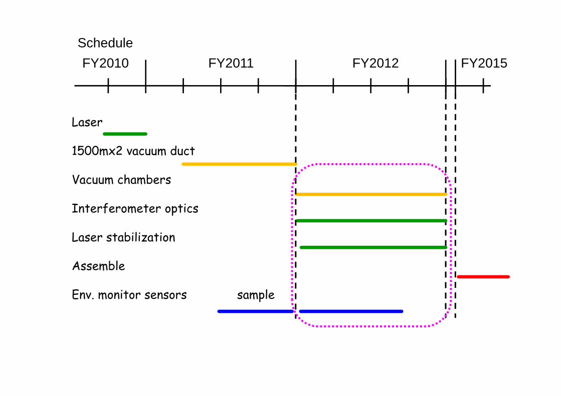
ScheduleFY2010 FY2011 FY2012 FY2015
Laser
1500mx2 vacuum duct
Vacuum chambers
Interferometer optics
Laser stabilization
Assemble
Env. monitor sensors sample

Layout around a vacuum chamber
KAGRA
GIF
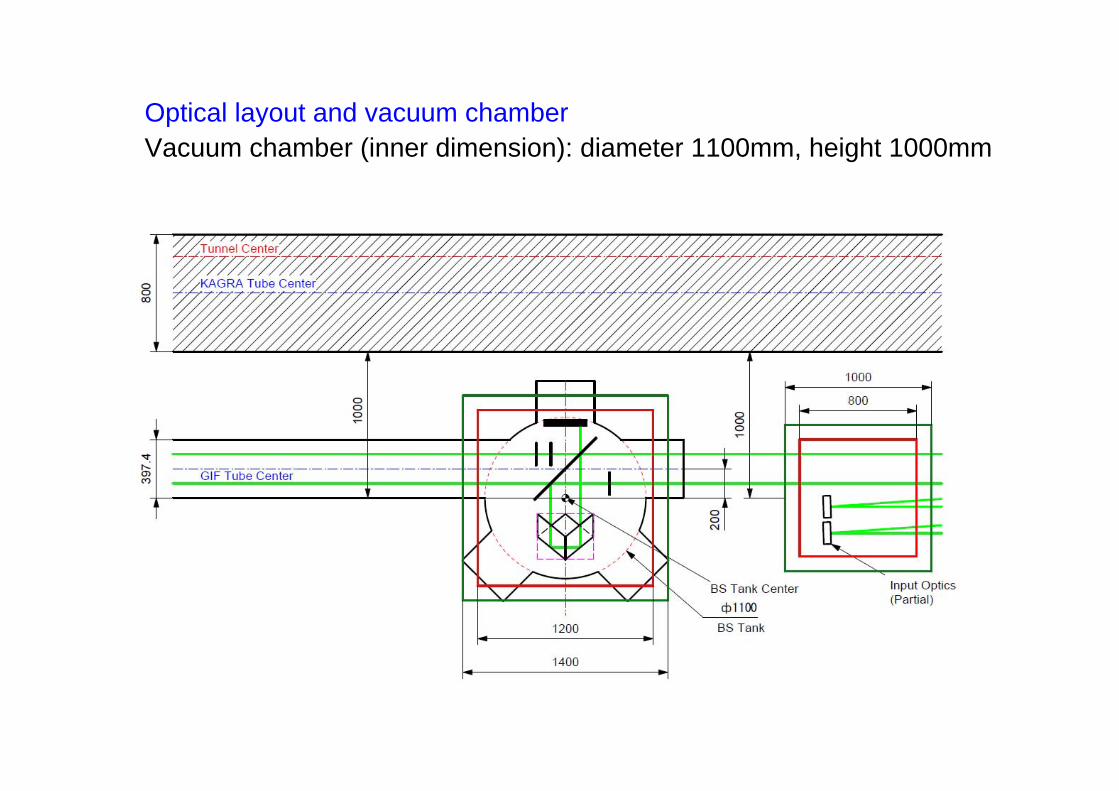
Optical layout and vacuum chamberVacuum chamber (inner dimension): diameter 1100mm, height 1000mm

nd a vacuum chamber (Input side)
One arrow indicates 1 meter.
Layout around a vacuum chamber
Vacuum chamber (inner dimension): diameter 1100mm, height 1000mm
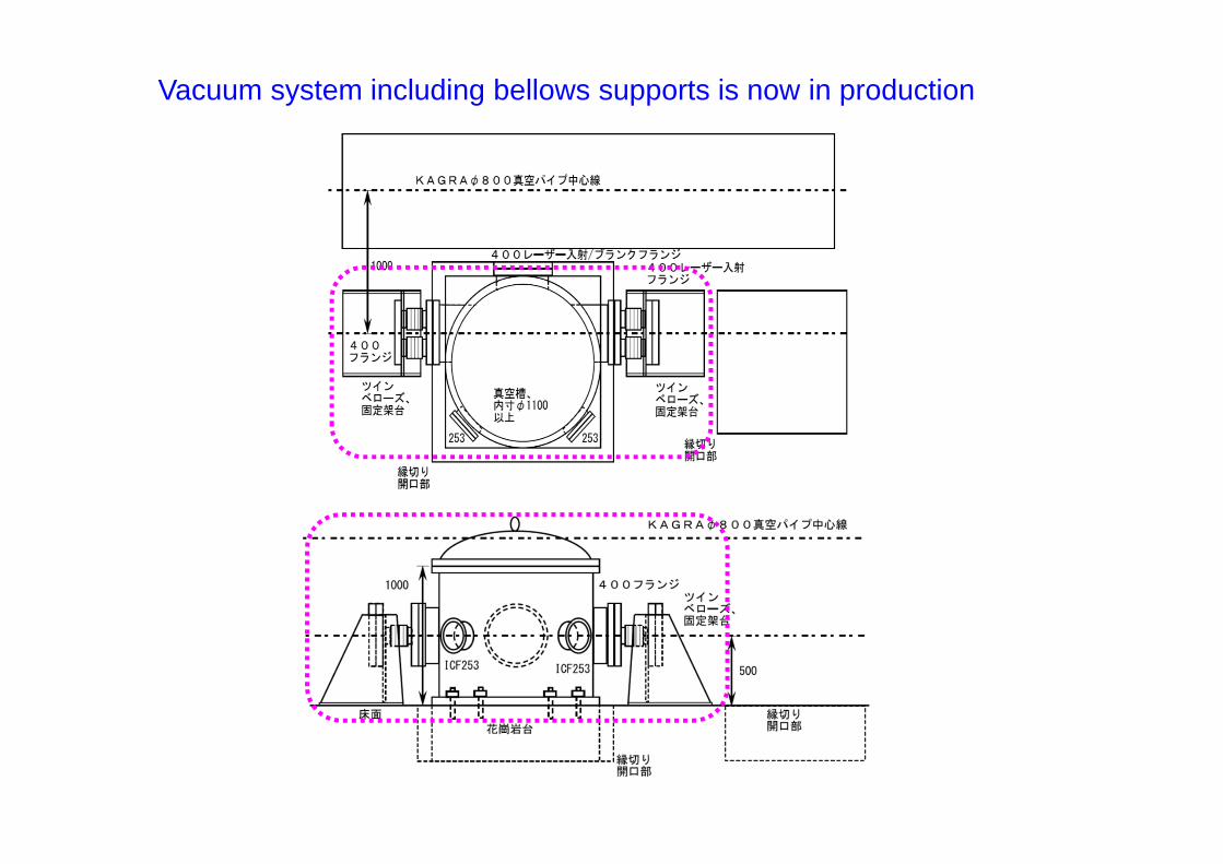
Vacuum system including bellows supports is now in production

Optics in Main Tank
• 15” Hollow Retroreflector• BS Separated to 2 pcs.• WP w/ 85 mm Apertures
Hollow Retroreflector

Surface Accuracy of Retroreflectors– A Manufacturer Specification (PLX)
• 0.3 Guaranteed• 0.1 Best effort
• Estimated Visibility DegradationVisibilities
0.05 +/- 0.03 (0.3 )0.21 +/- 0.03 (0.2 )0.53 +/- 0.02 (0.1 )
0.8
0.6
0.4
0.2
0.0
Visi
bilit
y
1.00.80.60.40.20.0
R (Roughness, x (633 nm))
Number of Mesh 10 x 10 50 x 50 100 x 100 200 x 200 gaussian fit

GIF Laser• Design & Implementation
– Lock Laser Frequency to an I2 Absorption Line• Highly Stable Quantum Standard• Frequency-Doubled Nd: YAG Laser (532 nm)
– Modulation Transfer Technique• Doppler-free detection of the absorption line
– Double Modulation• AM and FM applied to pump beam
– to resolve absorption lines (AM) and its derivative (FM)
• AOM used to apply both modulations

GIF Laser
• Full System DiagramDouble Modulation
AM Freq: 96.7 kHzFM Freq: 6.1 kHz(generated from the same OSC)
Two Feedback LoopsFast Loop:
Fed back to PZTLock Acquisition
Slow Loop:Fed back to YAG Temp.Long-Term Stabilization

GIF Laser
7th KAGRA f2f meeting
122013/02/15

GIF Laser

GIF Laser
• Experimental Results
7th KAGRA f2f meeting
142013/02/15
0.70
0.60
0.50VPD
1 [V
]
500x103450400350300250
Laser Frequency (a.u.)
-2.5
-2.0
-1.5
-1.0
-0.5
AM
Dem
od [V
]
0.3
0.2
0.1
0.0
-0.1FM D
emod
[V]
1110 absorption peak
FWHM: 4.6 MHz
Intensity of Probe BeamDoppler-broadened
AM Demodulated SignalAbsorption Lines Resolved
FM Demodulated SignalError Signal for Servo
0.3
0.2
0.1
0.0
-0.1
FM D
emod
[V]
84.0
x103
83.5
83.0
82.5
82.0
81.5
Laser Frequency (a.u.)

GIF LaserWider feedback bandwidth attained (50Hz->380Hz)
• Experimental Results
PZT (Fast) Loop Trf.UGF ~ 380 Hz
-100
0
100
Phas
e [d
eg]
10-1
100
101
102
103
104
Frequency [Hz]
10-4
10-3
10-2
10-1
100
101
Mag
nitu
de
PZT Open Loop TRF
UGF ~ 380 Hz
measurement (rough) estimation 0.01
0.1
1
10
Mag
nitu
de0.1 1 10
Frequency [Hz]
-100
0
100
Phas
e [d
eg]
Thermal Open Loop TRF
with PZT Loop Closed
measurement (rough) estimation
UGF ~ 2 Hz
Thermal (Slow) Loop Trf.UGF ~ 2 Hz, DC Gain ~ 50

GIF Laser• Status & Plan
• achieved long-term stable operation– Final Implementation Being Commissioned
• revising and optimizing optics and electronics– Delivery of Second System (not yet scheduled)
• as a backup• used for performance evaluation
– beat measurement to estimate frequency stability

Environment monitor (EM)
Environment condition of the tunnel, rooms, and instruments need tobe monitored for ensuring stable operation of detectors, correction ofdata analyses, and detection of anomalous operation.
Some sensors are directly attached to instruments for monitoring anynoises applied to the instruments to assess validity of the data, such asveto analyses.
The sensors are characterized by physical quantity, relative / absolute,dimension, measurement range, resolution, and frequency response.


already tested to be tested

Temperature, humidity, and barometric pressure at CLIOPower interruption on 25 May

Milestones (Geophysics interferometer)related sub-groups
2012.3 vacuum pipes delivery Vacuumoptics final design TunnelEM sensor determination Det Char
2012.9 vacuum valves / pumps delivery Vacuuminfra specification (clean booth, LAN) Fac. Sup.
2013.3 optical components deliveryvacuum components delivery VacuumEM sensors delivery Det Char
(2014.3) tunnel excavated Tunnel2014.6 vacuum & granite base installation Vacuum/ Fac. Sup.2014.12 vacuum installation Vacuum2015.3 optics installation
EM-DAQ operation Det Char2015.6 test observation start
safety management Fac. Sup.2015.9 observation & maintenance(2018.3) bKAGRA

Items to be purchased in FY2013
Optics mounts and breadboards
Vacuum pipes, valves, gauges, pumps
Environment sensors

Arrangement of vacuum pipes …. 22.5m x 2 are lacking for 1500m x 2 baseline

already tested to be tested