Deep Sucker Rod Pumpin for Gas Well Unloading
8
SPE ===wof~ En@saea of AiME SPE 13199 Deep Sucker Rod Pumping for Gas Well Unloading byL.JHenderson, Exxon Co. U.S.A. SPE Member Copyright 1984 Society of Petroleum Engineers of AIME ... Ths paper was presented at the 59th Annual Technical Conference and ExhibitIon held m Houston, Texas, September 16-19, 1984. The material is sub- ject to correction by the author. Permission to copy IS restricted to an abstract of not more than 300 words. Write SPE, 6200 North Central Expressway, Drawer 64706, Dallas, Texas 75206 USA. Telex 730989 SPEDAL 4BSTRACT MECHANICAL AND WELLBORl CONDITIONS Exxon Company, U.S.A.‘s Pyote Gas Unit 14-1 in the Block 16 (Ellenburger) field became the world’s deepest Figures 1 and 2 illustrate the mechanical condition of Pyote Gas Unit 14-1 before the artificial lift rod pumped Well on October 7, 1983. The rod pump was installation. Mechanical and wellbore conditions af- installed at 16,850 ft. in an attempt to extend the fecting the artificial lift installation include the prcduc~ive life of the well. The artificial lift system following: ~as designed to lift wellbore fluid that was restrictiiig the flow of gas, thus allowing the gas to be produced up the tubing-casing annulus. . The wellbore was deviated less than 2 1/2°/100 Implementation of the pro- ft. ject was possible because of the recent improvements in predictive techniques, materials available for rod A permanent production packer was set at 13,775 pumping, and industry’s experience in artificial lift. ● ft. INTRODUCTION ● A permanently attached tailpipe below the packer Exxon Company, U.S.A.’S Pyote Gas Unit 14-1 is a had a minimum internal diameter of 2.25 in. gas well in the Block 16 (Ellenburger) field located in ● Ward Co., Texas. The 5 in. production caeing was set at 17,07G ft. This West Texas gas field, initially rieveiopedin the 1?60’s, produces from 17,000 ft. by depletion drive and is currently 70% depleted. The 14-1 . Ellenburger perforations were from 16,294- 16,944 ft. was completed April 26, 1973 with an initial production rate of 3.8 MCFPD. As the bottom hole pressure s Flowing fluid level was located at 13,900 ft. decreased from 4500 psi to its current bottom hole (125 ft. below the packer) pressure of 1730 psi, the gas production steadily tirepped, Condensate and water could no longer be lifted ● by the gas, and fluid began to accumulate in the Static fluid level was located at 16,600 ft. wellbore and near wellbore region. By June of 1983, fluid buildup had reduced production to 50 kCFPD, at ● Bottom hole temperature was 250° F. which time a method of fluid removal was required to Production history euggested that, in an unloaded restore well productivity to recover the remaining condition, the well should be capable of producing 500 reserves. kCFPD with less than 20 BFPD. Enhanced gas pricing was necessary to make this EVALUATION OF ARTIFICIAL LIFT METHODS project economically feasible. Once it was granted by the gas purchaser, a rod pmp -. =r~ificial lift system was Mechanical, economic, designed and installed to restore well productivity by and reservoir constraints determined the choice of the artificial lift system Co removing 20 BFPD from a depth of 16,850 ft. The be used on the Pyote Gas Unit 14-1. As a result of the installation of this rod pumping system required use of state-of-the-art artificial lift technology and mate- risk involved in the installation, the following para- meter were established: minimize cost, utilize an rials. artificial lift system with a high salvage value, and minimize damage to the formation. Also, reservoir data on the well indicated the flowing fluid level was at 13,900 ft., References and illustration at end of paper. the flowing wellhead pressure was 500 psi, and the bottom hole pressure was 1730 psi.
-
Upload
nestor-orlando-gonzalez-p -
Category
Documents
-
view
44 -
download
3
Transcript of Deep Sucker Rod Pumpin for Gas Well Unloading

SPE===wof~ En@saea of AiME
SPE 13199
Deep Sucker Rod Pumping for Gas Well Unloading
byL.JHenderson, Exxon Co. U.S.A.
SPE Member
Copyright 1984 Society of Petroleum Engineers of AIME...
Ths paper was presented at the 59th Annual Technical Conference and ExhibitIon held m Houston, Texas, September16-19, 1984. The material is sub-ject to correction by the author. Permission to copy IS restricted to an abstract of not more than 300 words. Write SPE, 6200 North Central Expressway,Drawer 64706, Dallas, Texas 75206 USA. Telex 730989 SPEDAL
4BSTRACT MECHANICAL AND WELLBORl CONDITIONS
Exxon Company, U.S.A.‘s Pyote Gas Unit 14-1 in theBlock 16 (Ellenburger) field became the world’s deepest
Figures 1 and 2 illustrate the mechanical conditionof Pyote Gas Unit 14-1 before the artificial lift
rod pumped Well on October 7, 1983. The rod pump was installation. Mechanical and wellbore conditions af-installed at 16,850 ft. in an attempt to extend the fecting the artificial lift installation include theprcduc~ive life of the well. The artificial lift system following:~as designed to lift wellbore fluid that was restrictiiigthe flow of gas, thus allowing the gas to be produced upthe tubing-casing annulus.
. The wellbore was deviated less than 2 1/2°/100Implementation of the pro- ft.
ject was possible because of the recent improvements inpredictive techniques, materials available for rod A permanent production packer was set at 13,775pumping, and industry’s experience in artificial lift.
●
ft.
INTRODUCTION● A permanently attached tailpipe below the packer
Exxon Company, U.S.A.’S Pyote Gas Unit 14-1 is ahad a minimum internal diameter of 2.25 in.
gas well in the Block 16 (Ellenburger) field located in ●
Ward Co., Texas.The 5 in. production caeing was set at 17,07G ft.
This West Texas gas field, initiallyrieveiopedin the 1?60’s, produces from 17,000 ft. bydepletion drive and is currently 70% depleted. The 14-1
. Ellenburger perforations were from 16,294-16,944 ft.
was completed April 26, 1973 with an initial productionrate of 3.8 MCFPD . As the bottom hole pressure s Flowing fluid level was located at 13,900 ft.decreased from 4500 psi to its current bottom hole (125 ft. below the packer)pressure of 1730 psi, the gas production steadily
tirepped, Condensate and water could no longer be lifted ●
by the gas, and fluid began to accumulate in theStatic fluid level was located at 16,600 ft.
wellbore and near wellbore region. By June of 1983,
fluid buildup had reduced production to 50 kCFPD, at ●
Bottom hole temperature was 250° F.
which time a method of fluid removal was required to Production history euggested that, in an unloadedrestore well productivity to recover the remaining condition, the well should be capable of producing 500reserves. kCFPD with less than 20 BFPD.
Enhanced gas pricing was necessary to make this EVALUATION OF ARTIFICIAL LIFT METHODSproject economically feasible. Once it was granted bythe gas purchaser, a rod pmp -.=r~ificial lift system was Mechanical, economic,designed and installed to restore well productivity by
and reservoir constraintsdetermined the choice of the artificial lift system Co
removing 20 BFPD from a depth of 16,850 ft. The be used on the Pyote Gas Unit 14-1. As a result of theinstallation of this rod pumping system required use ofstate-of-the-art artificial lift technology and mate-
risk involved in the installation, the following para-meter were established: minimize cost, utilize an
rials. artificial lift system with a high salvage value, andminimize damage to the formation. Also, reservoir dataon the well indicated the flowing fluid level was at13,900 ft.,
References and illustration at end of paper.the flowing wellhead pressure was 500 psi,
and the bottom hole pressure was 1730 psi.

DEEP SUCRER ROD PUMPING FOR GAS WELL UNLOADING SPE 13199
With these guidelines set, three artificial lift:ystems were considered as candidates for removing
K?llbore fluid from the Pyote Gas Unit 14-1. The systems,valuatedwere gas lift, plunger lift, and rod pum~~~l~.
he to the low bottom hole pressure of the formation itms determined that removing the packer would be costly~nd large amounts of fluid wouid be lost : ● n.nc” ~~~
.eservoir. Since gas lift would require the in-stallation of gas lift valves below the flowing fluid.evel, installation of this system would mandate the“emoval of the existing packer and was therefore:liminated from consideration. Also, plunger liftmoved unacceptable due to the insufficient bottom holepressure and location of the packer.
Rod pumping was chosen because an artificial lift;ystem could be designed to pump from below the perfo-rations without removing the packer. This option was~adepossible by the recent development of lightweight,Iigh tensile strength 1 1/4 in. fiberglass rods. Theexperimental nature and economics of the test dictated:hat high salvage value equipment and the e.+isting:ubulars be used wherever possible to minimize the?conomic impact of an unsuccessful test.
)ESIGN PROGRAM
A computer program aided in the design of the Pyote;as Unit 14-1 installation. “Leyinpitita~.d cmtput data]sed in the design were:
INPUT
Pump DepthPumping Unit TypeMotor TypePump Plunger DiameterPumping SpeedStroke LengthRod String (Length and Diameter)E,Zr.berof Cycles AnalyzedPump Intake PressureFlowiine P~~SSiiie
Tubing Fluid GradientTubing Anchor OptionPump Load AdjustmentPump Fillage
OUTPUT
Power RequiredPolished Rod HorsepowerMotor Speed VariationPeak Polished Rod LoadMinimum Polished Rod LoadMaximum StressMinimum StressAverage Pumping SpeedMaximum TorqueRequired CounterbalanceDownhole Rod Loading for Each TaperTubing StretchLost Displacement Due to Tubing StretchGross/Net Pump StrokeGross/Net Displacement
As a precautionary measiire,... ...*ho rod-tubing frictionPump Load Adjustment) was assumed to be twice the nor-
mal amount. Also, it was assumed that 20 in. of pumpdisplacement was lost to gas interference (Pump Fill-age).
TUBING DESIGN CONSIDERATIONS
The tubing used in the Pyote Gas Unit 14-1 had tofulfill a number of requirements. Primarily,it had tomeet the requirements for burst resistance and tensilestrength. It was also necessary for the tubing to meetthe physical constraints of the wellbore. To minimizecost, every attempt was made to incorporate the existingtubulars into the design.
To remove the fluid and to minimize gas interfer-ence and gas locking, the pump had to be set at or belowthe perforations (16,900 ft. or 3125 ft. below the per-manent packer). To accomplish this without removing thepacker, it was necessary to use a tapered tubing string.Once the tailpipe was removed the minimum internal dia-meter thru the packer was 2.441 in., thus limiting thetubing size below the packer to 1.9 in. (2.113 in. maxi-fiumdiame~er),
Load calculations were performed to evaluate thefeasibility of using a tapered 2.875 in. x 1.9 in.tubing string. Table 1 gives tensile loads for thethree cases considered: Case 1 assumed the tubing wasanchored at 13,500 ft. Case 2 assumed the tubing to befull of 9.1 ppg brine water, czrryi~g the entire rodstring load, and supported only at the surface. Case 3used the same assumptions as Case 2 but included a
. . l-l5nn ft.tubing drain valve at ......
As seen in Table 1, loads for Case . ~,,~~ .......~ --a ? ovreeded
and approached the joint yield strength of the 2.875 in.tubing. However, Case 3 was chosen in view of themechanical and economic nature of the project. A tubinganchor set in 15,000 lb. tension with a 30,000 lb. shearwas selected. As an added safety factor, a fluted subwas designed and placed directly above the packer tos,~pport the tubing if it were to part.
Burst re~i~tance calculations were done for the
2.875 in. x 1.9 in. tubing string. The burst resistancecalculations assumed the tubing was full of 9.1 ppgbrine water, the tubing-casing annulus was dry, and1000 psi was required to open the tubing drain valve. Asseen in Table 2, the burst resistance loads for the2.875 in. x 1.9 in. tubing were below their upper opera-ting limits.
Once the tubing design was selected, the permanenttail assembly had to be removed and the 2.875 in. tubinghad to be unlatched from the permanent packer. The tailassembly, shown in Figure 2, was removed with a 2.25 in.jet cutter and was allowed to fall to the bottom of thewell. The 2.875 in. tubing was then removed, and a 2.875in. x 1.9 in. tapered tubing string was installed asshown in Figure 3. The pump barrel was set at 16,850 ft.with an open-ended joint of tubing below the pump.
ROD DESIGN CONSIDERATIONS
High strength steei and fiberglass rods were ini-tially considered for the Pyote Gas Unit 14-1artificial lift installation. The tensile load limita-tions of an aii Ste~i rod string were identified

;PE 13199 LEE J. HENDERSON 3
[uickly and eliminated early in the design phase of themoject. Problems such as the rod size required to~ithstand the tensile loads and the pumping unit size“equired ruled out an all steel rod design.
Fiberglass rods were an attractive alternative. . > l:~l.+.,.,m;~h~)ecauseof their hugh tensile strengcn arm LLS1,G.-U.o.-.
.1
;Omputer ~a~cu~ations of tensile and cyclic loads re-
realed that 1 in. fiberglass rods had sufficient tensiie;trength, but it was questionable if any downhole pump]troke could be achieved due to the stretch of the rods.calculations for 1 1/4 in. fiberglass rods indicated:hey could withstand the tensile.loads and attain the:equired downhole pump stroke. Also, with 1 1/4 in.:iberglass rods, the existing 2.875 in. tubing could be]sed; and, since the rods weighed 1.4 ppf, the pumpingknit size could be reduced in comparison to an all steel:od design.
The computer program was then used to refine the rod;tring design. Using a fluid gradient of 0.433 psi/ft.md a pump intake pressure of 500 psi, pumping para-meters such as stroke length, strokes per minute andmmp size were varied and evaluated to determine the:od string design. The mechanical constraints of the1.9 in. tubing determined the rod design below the>acker. The rod string selected consisted of the:ollowing: (from top to bottom)
7,42s ft. - 1 1/4 in. fiberglass rods2,200 ft. - 1 in. Grade “D” steei rods2,100 ft. - 7/8 in. Grade “D” steel rods1,900 ft. - 3/4 in. Grade “D” steel rods3,225 ft. - 5/8 in. high strength steel rods
16,850 ft.
The fiberglass rods were designed to operate within:heenvelope of the stress range diagram shown on Figureb. The Grade “D” rods were predicted to operate within:he limits of the modified Goodman diagram shown on~igure 5, while the high strength steel rods would>perate between O - 50,000 psi. The final design met:he operating constraints of each rod type.
?UMPING UNIT
Beam units can be classified into three categories:conventional class I lever system, Mark 11 class 111lever system, and the air balanced class 111 lever;ystem. The operating principle for all three units is:he same. The walking beamis activated by a crank whichis connected to a reducer and powered by a prime mover.
Any of the three units mentioned above could have>een used for the installation with only small modifi-cations to each system. However, a conventional unittas chosen because of the reduced rod load range with anlltra high slip motor, decreased acceleration and ve-locityof the rods on the downstroke, and relatively low
maintenance costs.
Using the following input parameters:
● Pump Set at 16,850 ft.● 1 1/16 in. Plunger● 8.5 Strokes Per Minute● 168 in. Stroke Length● 500 psi Pump Intake Pressure● 0.443 paifft. Fluid Gradient
the maximum torque and peak poiished rod i~ad for aconveniiofialunit were predicted to be 527,900 in.-lbs.and 31,235 lbs., respectively. Based on this predictiona conventional unit with a 640,000 in.-lbs. gear reducerand a structure rating of 36,500 lbs. was selected.
PRIME MOVERS
Standard Nema D and ultra high slip electric motorswere evaluated as potential prime movers. The primaryrequirement in motor selection was to maximize thespeed variation to reduce rod loading. Since the Nema Dmota has a reiativel~ small amount of speed variation
(0-12% at full load) it was less desirable for thisproject. Conversely, the ultra high slip motor canattain apeed variations from 0-50% by varying its elec-trical resistance.
Two advantages can be derived from the largeamounts of speed variation present in the ultra highslip motor. The first of these is obtained from therotary inertia effects of the cranks and weights. Asthe weights and cranks slow down, energy is given upwhich reduces part of the torque load on the reducer.
The second advantage is less severe rod loading. h.ietomotor deceleration during periods of peak torque, theupward acceleration and velocity of the rod string isreduced, resulting in lower peak stress. Also, due toits abiiit~ co red!u~edownward acceleration and veloc-ity, the minimum rod stress is increased. Thus the rodload range is reduced.
Using a computer program it was determined that a40 HP motor would be required to operate the conven-tional pumping unit. An ultra high slip motor wasselected with an operating range of 30.5 to 72.0 HP fromthe low to high mode, respectively. In operation themedium slip mode was used.
PUMP
The pump had to be set at or below the perforations,fit inside the 1.9 in. diameter tubing, and withstand amaximum hydrostatic load of 8000 psi. The pump wouldalso have to withstand a bottom hole temperature of 250°F and be capable of pumping 20 BFPD. To be on theconservative side, it was assumed the fluid in thewellbore would be all water and lubrication from con-densate would be minimal.
A 1 1/2 in.x 1 1/16 in. x 36 ft. tubing pump wasselected. The greater wall thickness of the tubing pump(3/16 in. as opposed to 1/8 in. with a rod insert pump)was required to withstand the hydrostatic loada. Add i-tionally, segmented barrels could be joined together tomake a 36 ft. •l*h;~opump. To.U----_ reduce friction, theinterior of the barrel was chrome plated and theplunger was spraymetai coated. TO reduce ~iipp~ge, a 6ft. plunger with a -0.003 in. fit and double standingvalves and traveling valves were used. Table 3 lists thepump parts and their corresponding metallurgy.

.4 DEEP SUCKER ROD PUMPING FOR GAS WELL UNLOADING SPE 13199
‘uMP-OFF CONTROLLER
To avoid possible damage to the rod string or;urface equipment from continuous pumping, a pump-off:ontroller was installed. A pump-off controller is aIevicewhich controls pumping time by sensing pump-off.‘ump-off in a well occurs when complete liquid fillage]t the pump does not occur.
The pump-off controller chosen used a micropro-:esaor based logic system that senses changes in thejolished rod loading from a transducer that is mountedm the walking beam. The signals are gathered at the:ransaucsr and sre transmitted to the controller, which.smounted on a pole near the pumping unit. Duriitg 28C!’)
:ycle the controller checks for pump-off by integrating:hearea limit between a line drawn through minimum loadmd the load curve during a portion of the downstroke.f the area measured is greater than the predeterminedLimit set by the operator, the controller considers theJell to be pumped off and shuts the pumping unit down.
The operator entries which control the mode of)peration as described in the previous paragraph are asfollows:
. Off Time - Time the well is shut in for refill.
● Pump up - Time the well is pumped beforemeasurement begins.
● Limit - A predetermined area as describedin the paragraph above.
● Pump Off Count - Number of consecutive puulp-off strokes before shutdown.
:he pump-off controller used on the Pyote Gas Unit 14-1incorporated the following safety features:
. An alarm light automatically turnson if the wellruns for more than 95% of the time during anoperating day without sensing pump-off.
9 If a problem exists with the signal to thecontroller or ip.validinformation is received,
the controller automatically reverts to a per-centage timer. The well will then shut in forthe number of minutes programed into off timeand would run for the same amount of run timerecorded for the previous week.
. The controller monitors and shuts off the unitif a loss of load, as would be seen with a deeprod part, occurs.
The pump-off controller parameters used to controlhe mode of operation for the Pyote Gas Unit 14-1 areisted below:
. Off Time - 15 min.● Pump Up - 1 min.● Limit - 200● Pump Off Count - 1
3ESIGE VS. OPERATING DATA
The table below compares the data predicted from thecomputer program with an actual dynamometer analysis
ACTUALCOMPUTER DYNAMOMETERPROGRAM ANALYSIS
Strokes Per Minute 8.5 8.0Surface Stroke Length (in.) 169.8 169.3Sross Plunger Travel (in.) 137.0 165.0Zear Box Torque (in.-lbs.) 527,900 584,000Beam Load (lbs.) 31,324 29,073!laximumRod Stress (psi) 25,452 23,690Minimum Rod Stress (psi) 16,549 14,767
9PERATING EVALUATION
As seen in the previous section, the loads pre-dicted by the computer program closely matched theactual loads on the equipment. The well also success-fully pumped fluid and increased gas production sub-stantially with fluid and gas rates as high as 70 BFPD(40% pump efficiency) and 450kCFPD, respectively. Therods and surface equipment successfully operated in therange outlined by the manufacturer. Due to the clear-ance of the pump (-0.003 in.), problems were encounteredwith the pump sticking; however, this problem should besolved with the installation of a larger clearance pump.Field experience with the pump-off controller was un-favorable because of rod damping and gas interference.Therefore, to minimize system damage, an intermittentoperatin-gschedule was utilized. Based on early pro-duction test data, the well was pumped one day per week.Production did not appear to be hampered by thisschedule and is being maintained.
CONCLUSIONS
Based on the field experience gained by rod pumpingthe Pyote Gas Unit 14-1, the following conclusions aresupported:
c Enhanced gas recovery is possible by utilizingdeep rod pumping.
● Rod pumping is a viable method of unloadingdeep, low-fluid producing gas wells.
● Lightweight, high strength fiberglass rods can beused to extend the depths of rod pumping.
Q Computer programs are available that can success-fully model deep, complex fiberglass rod stringperformance.
!CKNOWZEDGEHFXTS
The author would like to express his appreciation:0 the following individuals: D. M. Adams, P. G.;avazos, Jr., S. G. Gibbs, T. B. Fulton, K. B. Nolen, R... Soza, C. M. Upton, J. T. West, and G. H. Hacke.

SPE 13199....
REFERENCES
1.
2.
3.
Gibbs. S. G.,
LEE J. H...-. . . - ..--------
- Users Manual for NABLA CorporationTime Shared Computer Programs, NABLA Corporation
(August, 1978).
Gibbs, S. G. and Nolen, K. B., Principles of RodPumping, NABLA Corporation (January, 1975).
“Series 700cs Beam Pump Controller TechnicalCIata %eet”% End Devices, Incorporated (October,1982).
TABLE 1
TENSILE LOADS
Tensile Load on *Joint Yield Strength ofTop Joint 2.B75 in. 6.5ppflC-75Tubing
Case (lbs.) (lbs.)
1 102,800 135,900
2 153,400 135,900
3 129,500 135,900
*Reproduced from API Bulletin 5c2 18th Edition March 1982
TABLE 2
BURST REsISTANCELOADS
InternalPressureTubing Size Exerted on the Tubing *Tubing Burstand Grade (psi) (psi)
2.B75 in.6.5pPE/C-75 7500 9910
1.90 in,2.9ppf/N-80 9000
o !7..:- C.rJl~rh pditio” March 1982*Reproduced trom AFi DUL!=....... ..
>ERSON 5_,,_ ..-------...... . ..... ...—.... . ..--...-. ---
TABLE 3
PuMP METALLURGY
,RKSLASSEMBLY
Part Description
Barrel Coupling
Barrel (Chrome Plated I.D.)(32 ft.)
Pup Joint (4 ft.)
P“p Joint Coupling
Barrel Cage (Double
Balls
Seats
Coupling
Bushing (Seat)
LUNGER ASSEMBLY
VEIve Rod Bushing
Valve Rod
Plunger Cage (Double
...--...)Piunger (SpraYUI=L=.j
Balls
Seats
Rod Coupling
Valve Rod Connector
Valve)
Valved)
Pump Material
862o Cold Rolled Steel
1023/1026 Electric ResistanJWelded Steel
N-80 Seamless Steel
8620 Cold Rolled
gGr,e ~
Stellite
Tungsten Carbide
8620 Cold Rolled
1215 Steel
Mone1
Steel
Steel
8620 Cold Rolled Steei
MOne1
1026 CoId Drawn Steel withSpraynketalCoating
Stellite
Tungsten Carbide
Mone1
Hone1
FIG. 1 - WELLBORE BEFORE ARTIFICIAL
LIFT INSTALLATION
I .
,2.875 h.6.S PWC-75TUBING
ERMANENT PACKERAi i3,775 ft.
-.-- ....
-i6!!!kFLOWING FLUID LEVELAT lS,SOOtt.
ELLENBURGER PERFORATIONSSTATIC FLWOLEVEL AT 16,294- lS,S44tt.ATl%OOO ft. 51n. CASINQAT 17,070tt.
PBO 17,016 ft. TD 17,070tt.
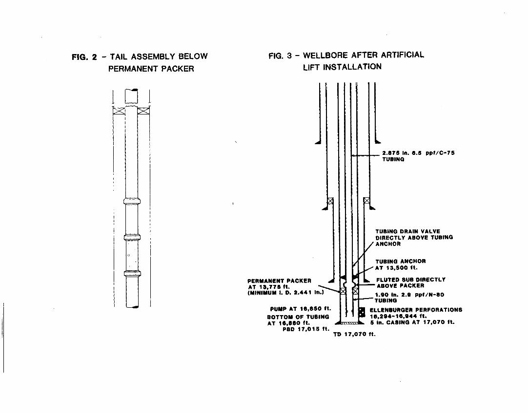
FIG. 2 - TAIL, ASSEMBLY BELOW
PERMANENT PACKER
ml
FIG. 3- WELLf30RE AFTER ARTIFICIAL
LIFT INSTALLATION
}
2.87S in.TUBING
6.5 ppf/c-75
A
U’1h
TUBING DRAIN VALVEDIRECTLY ABOVE TUBINGANCHOR
TUBING ANCHORAT i 3,S00 ft.
PERMANENT PACKER
‘%
J FLUTED SUB DIRECTLYAT 13,77S ft. ABOVE PACKER(MINIMUM L D. 2.441 In.) 1.90 in. 2.s ppf/N-80
TUBING
PUMP AT 16,S50 ft. ELLENBURGER PERFORATIONSBOTTOM OF TUEIING 18,2S4-*6,944 ft.AT 16.8S0 ft. 5 in. CASING AT 17,070 ft.
PBD 17,01!5 ft.TD 17,070 ft.

FIGI. 4- STRESS RANGE DIAGRAM FOR
I 1/4 IN. FIBERGLASS RODS
3(0,000
25,000
‘15,000
10,000
5,00C
I 1 \1’____ .It ,
—.. -—.- +’ ‘i; --;-.4. .; ..-: .--, . .
...
.. ——-,,
..__~.:1
FIG. 5- MODIFIED GOODMAN DIAGRAM
70,0~D0 ~66,000 PSI, API-D” RODS
so,a)oo
9-6 .;
iii
2000(0-
17-:::.::.::::..:.::::.::..:..:::..-:::..:::::.::::”: .:. . . .. . . . .. . . . . . . . .... . . . . . . . .::”:”:”............................. ........ ~::.:..
jo,o($o ““:;:..;;.””:’:...:”:.:...........:.........:.:..:..:..:...:....
o reproduced from APIRP 1lBR 5th Edltlon
March 1965
.

---