Dec 2010 AAVP Cambridge workshop AAVP AAVS1/2-low demonstrators Jan Geralt Bij de Vaate.
16
Dec 2010 AAVP Cambridge workshop AAVP AAVS1/2-low demonstrators AAVS1/2-low demonstrators Jan Geralt Bij de Vaate
-
date post
22-Dec-2015 -
Category
Documents
-
view
214 -
download
1
Transcript of Dec 2010 AAVP Cambridge workshop AAVP AAVS1/2-low demonstrators Jan Geralt Bij de Vaate.
Dec 2010 AAVP Cambridge workshop AAVP
AAVS1/2-low demonstratorsAAVS1/2-low demonstrators
Jan Geralt Bij de Vaate

Dec 2010 AAVP Cambridge workshop AAVP
Tile Digitisation
Tile Digitisation
Element
Digitisation
RFI Shielded
......
......
...
......
...
Power DistributionPower Distribution
Element Digitisation
...
CoolingCooling
Element Digitisation
......
Station Processing
RFI shielded
System clock
Control &Monitoring
StationBeams
PowerGrid
Element Data
C & M
Clock
To Correlator
& Services
2x 500MHzAnalogue+ power
FibreCopper
2-PolElements
Front-end
SKASKA11: AA-low : AA-low
stationstation
Each station:
Diameter: 180m# of elements: 11,300Element links: Copper

Dec 2010 AAVP Cambridge workshop AAVP
Proposed specificationProposed specification
• From draft SKA phase 1 system description, June 2010

Dec 2010 AAVP Cambridge workshop AAVP
After the 50MHz issue..After the 50MHz issue..
• And LOFAR / MWA /..
• AAVS-low needs to address– Broadband Aeff / Tsys (antenna, lna, beamforming)
– Broadband receiver
– Cost effective signal processing
– Calibration
– Monitoring & Control
• Some specs need new developments
• Some (just) need proper choices– Note: one array for 50-450MHz not possible

Dec 2010 AAVP Cambridge workshop AAVP
AA-low antenna designAA-low antenna design
• Addressed by– UCAM
– INAF / IEIIT-CNR
– ICRAR
– ASTRON (2011)
• ~10 full scale antenna prototypes build 2011
• Action– Agree on test approach/range
– Extend analyses for scan angle and frequency
Razavi 2010Wijnholds 2010

Dec 2010 AAVP Cambridge workshop AAVP
AA-low stationAA-low station
• Addressed by– UCAM
– UMAN
– 2011..ICRAR, ASTRON
• Many options
• Action– Form (small) focussed team
– AAVP, SPDO domain spec and scientist , ‘AA’ astronomer
Ap 1.5 km2 0.84 km2 0.59 km2 0.42 km2
Freq Tsys Ae8/Ts Ae16/Ts Ae32/Ts Ae64/Ts
MHz K m2 K-1 m2 K-1 m2 K-1 m2 K-1
43 9400 160 90 65 45
60 4000 375 210 150 105
85* 1600 940* 525 370 265
120* 700 1070 1200* 840 600
170* 320 1170 1310 1840* 1315
240* 160 1310 1840 2625*
340 85 1735 2470
480 60 1750
Bregman 2010
Dec 2010 AAVP Cambridge workshop AAVP
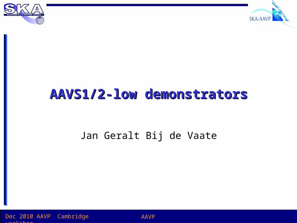
Deployment cost
Freq bandwidth
Aeff /Tsys Dynamic range
Random elements High Good Optimal Optimal
Random tiles Moderate Good Good Good
Regular grid tiles Low Optimal Good (strong gratings)
Some trade offsSome trade offs
-LOFAR, MWA, AAVP will need to confirm/complete the trade-offs-More: Filling factor, uv coverage, calibration, FoV etc..

Dec 2010 AAVP Cambridge workshop AAVP
AA-low LNAAA-low LNA
• Addressed by – INAF
– ICRAR
– UMAN
• Should not be an issue but– Coupling
– Impedance, 50, 150, 300 Ohm
– Differential
LOFAR simulation, Kant
Dec 2010 AAVP Cambridge workshop AAVP
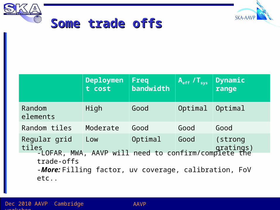
AA-low receiverAA-low receiver
• 6, 8 or 12 bits needed– 8 fine?
• SPDO: please release new RFI data!
• RFI at 55MHz (not in this plot)– Levels??
– 50-70MHz does not come for free
• Action– Requirements analyses: ASTRON+SPDO
CoDR docs

Dec 2010 AAVP Cambridge workshop AAVP
AA-low costing AA-low costing
• Analogies costing– LOFAR
– MWA
• AA station model input by AAVP PE and AA domain specialist

Dec 2010 AAVP Cambridge workshop AAVP
AAVS rationaleAAVS rationale
• Prototyping essential
• LOFAR initial test station and CS1, MWA 32T– Antenna array needs adequate receivers and back-end
– Test software
• Common test platform needed!– For AA-low options & AA-mid
– Site: Sufficient low RFI, fibre link, power,
– Signal processing (limited bandwidth?)
• Action– Define requirements test platform

Dec 2010 AAVP Cambridge workshop AAVP
AAVS1: AA-lowAAVS1: AA-low
• Demonstrate electromagnetic and front end performance– Sufficient collecting area (250-500m2?), possibly two versions
– Focus on broadband antenna and front-end design
– Evaluation using existing processing• UNIBOARD, ROACH or LOFAR / MWA
– Goal: establish antenna, tile and station configuration• Extensive station simulations required
– Critical Design Review 31-12-2011
– Commissioning 31-12-2012
– Reporting 30-6-2013

Dec 2010 AAVP Cambridge workshop AAVP
AAVS1: AA-lowAAVS1: AA-low
• Actions– Specify AAVS1
– Based on SKA1 System Requirement Specification
– Hardware costs / resources
AA-lo 70 – 450 MHz Overlap with AA-hi to provide even sensitivityInst. Bandwidth 380MHz Combine both polarisations onto one
processing channelSystem Temp 120K At 300 MHz, Sky noise 50K, Trec 70KArray Type Sparse Increases Aeff at low frequency to part
counter Sky noiseScan angle ±45°Polarisations 2 linearTile size 64 Dual polarisation elementsNo. of Tiles 4
AAVP DoW March 2010, to be updated

Dec 2010 AAVP Cambridge workshop AAVP
AAVS2: AA-lowAAVS2: AA-low
• Pre production phase:– Preparing for mass-production, design for manufacturing
• AAVS2 prototype– Test tooled production components
– SKA1 performance compliance
– Bandwidth, Tsys, stability, signal processing, calibratability, climate
– Critical Design Review 30-9-2013
– Construction 2014
– Comisioning 2015
– Reporting for SKA1 PR 31-12-2015

Dec 2010 AAVP Cambridge workshop AAVP
AAVS2 requirementsAAVS2 requirements
• In order to ramp-up production in 2016, AAVS2 should be sufficiently large: e.g. 1-2% SKA1 (~10.000 elements)
• Built with SKA1 tooling
• A couple of ‘d’ diameter stationsincluding digital station beamforming – Note: e.g. if used UNIBOARD 2 needs to production ready by 2014
• On the SKA site
• Acceptance tests of this station should be considered in absence of correlator
Schedule is tight: custom MMICs, photonic links,
signal processing boards

Dec 2010 AAVP Cambridge workshop AAVP
AA-lowAA-low
• Montly telecons
• Wiki for progress docs, minutes etc.– www.ska-aavp.eu/aavpwiki
• Workpackages– System design
– Antenna element, array
– Front-end (LNA, receiver, data link)
– Calibration & beamforming
– Proto type, Design, Construction & commisioning, Evaluation