DEAR VOLVO OWNER - az685612.vo.msecnd.net€¦ · Introduction .....6 Volvo Car Corporation and the...
247
Transcript of DEAR VOLVO OWNER - az685612.vo.msecnd.net€¦ · Introduction .....6 Volvo Car Corporation and the...


DEAR VOLVO OWNERTHANK YOU FOR CHOOSING VOLVO
We hope you will enjoy many years of driving pleasure in your Volvo. The car has been designed for the safety and comfort of you and your passengers. Volvo is one of the safest cars in the world. Your Volvo has also been designed to satisfy all cur-rent safety and environmental requirements.
In order to increase your enjoyment of the car, we recommend that you familiarise yourself with the equipment, instructions and maintenance information contained in this Owner’s Manual.

Contents
2
00 IntrodIntroductioVolvo Car Cenvironmen
02 Instruments and controlsOverview, left-hand drive car ............34Overview, right-hand drive car ..........36Driver’s door control panel ...............38Combined instrument panel .............39Indicator and warning symbols .........40Information display ...........................43Electrical socket and switch, centre console .............................................45Lighting panel ...................................46Left-hand stalk switch ......................48Right-hand stalk switch ....................50Cruise control (option) ......................52Steering wheel keypad (option) ........54Steering wheel adjustment, hazard warning flashers ................................55Parking brake, electrical socket ........56Power windows .................................57Rearview and door mirrors ...............59Power sunroof (option) ......................62Personal preferences ........................64
uctionn ........................................6orporation and the t ........................................7
01 SafetySeatbelts .......................................... 12Airbag system .................................. 15Airbags (SRS) ................................... 16Activating/deactivating the airbag (SRS) ..................................... 19Side airbags (SIPS bags) .................. 21Inflatable Curtain (IC) ....................... 23WHIPS .............................................. 24When the systems deploy ................ 26Crash mode ...................................... 27Child safety ...................................... 28

Contents
3
03 ClimGeneral incontrol ..Manual cElectronicECC (optAir distribFuel-drive
05 Locks and alarmRemote control with key blade .........94Keyless drive (option) .......................98Locking and unlocking ................... 100Alarm (option) ................................. 103
ate controlformation on climate
............................................ 68limate control, A/C ............. 70 climate control,
ion) ..................................... 72ution .................................. 75n heater (option) ............... 76
04 InteriorFront seats ........................................80Interior lighting ..................................82Storage spaces in the passenger compartment ....................................84Rear seat ...........................................86Cargo area ........................................87

Contents
4
06 StartinGeneral ...Refuelling Starting thKeyless drManual geaAutomatic Brake systStability ansystem ....Parking assBlind Spot(option) ....Towing andJump startDriving witTowing braDetachableLoading ...Adjusting h
08 Car careCleaning ..........................................162Touching up paintwork ....................165Rustproofing ...................................166
g and driving........................................ 108........................................ 110e engine ..........................111ive (option) ..................... 113rbox .............................. 114
gearbox ........................ 116em .................................. 119d traction control ........................................ 121istance (option) ............. 123
Information System BLIS ........................................ 125 recovery ....................... 128ing ................................. 130h a trailer ........................ 131cket ............................... 133 towbar ......................... 135
........................................ 140eadlamp pattern ........... 141
07 Wheels and tyresGeneral ........................................... 144Tyre pressure .................................. 148Warning triangle and spare wheel .. 150Changing wheels ............................ 151Emergency puncture repair ............ 153
Contents
5
09 MainVolvo serSelf-mainBonnet anDiesel ....Oils and fWiper blaBattery ..ReplacingFuses ....
11 SpecificationsType designation .............................220Dimensions and weights ................221Engine specifications .....................224Engine oil ........................................226Fluids and lubricants ......................230Fuel .................................................232Catalytic converter .........................234Electrical system ............................235
tenance and servicevice .................................. 170tenance ........................... 171d engine compartment .. 172
.......................................... 173luids .................................174des .................................. 178.......................................... 179 bulbs ............................. 181
.......................................... 187
10 Infotainment systemGeneral ...........................................196Audio functions ...............................197Radio functions ...............................199CD functions ...................................203Menu structure – audio system ......205Phone functions (option) .................206Menu structure – phone ..................213
Introduction
6
Intro
Owner
A good is to reayour firsportunitfunctionin differeuse of atention tthe man
The equmanual tion to sdescribeand cert
W
"Warnirisk of structio
IM
"Importo the cbeing f
duction
’s Manual
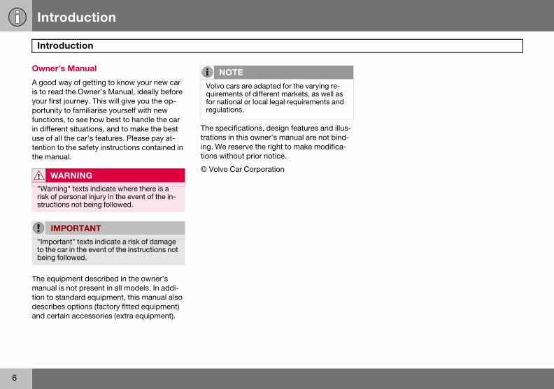
way of getting to know your new car d the Owner’s Manual, ideally before t journey. This will give you the op-y to familiarise yourself with new s, to see how best to handle the car nt situations, and to make the best
ll the car’s features. Please pay at-o the safety instructions contained in ual.
ipment described in the owner’s is not present in all models. In addi-tandard equipment, this manual also s options (factory fitted equipment) ain accessories (extra equipment).
The specifications, design features and illus-trations in this owner’s manual are not bind-ing. We reserve the right to make modifica-tions without prior notice.
© Volvo Car CorporationARNING
ng" texts indicate where there is a personal injury in the event of the in-ns not being followed.
PORTANT
tant" texts indicate a risk of damage ar in the event of the instructions not ollowed.
NOTE
Volvo cars are adapted for the varying re-quirements of different markets, as well as for national or local legal requirements and regulations.

Introduction
7
orporation and the environment
Volvo C
Environmthe threerationsalso belconside
Your Voenvironmfacturedsource-Car Corthe ISO standardthe envi
It is possible for the driver to influence fuel consumption. For more information read un-der the heading, Reducing environmental im-pact, on page 9.
Volvo Car C
ars’ environmental philosophy
ental care, safety and quality are e core values which influence all op- of the Volvo Car Corporation. We ieve that our customers share our ration for the environment.
lvo complies with strict international ental standards and is also manu-
in one of the cleanest and most re-efficient plants in the world. Volvo poration has global certification to 14001 environmental standard. This supports the work within the area of
ronment.
EPI (Environmental Product Information) is supplied for all Volvo models. There you can see how the car’s lifecycle affects the envi-ronment.
Read more at www.volvocars.com/EPI.
Fuel consumptionVolvo cars have competitive fuel consump-tion in each of their respective classes. Low-er fuel consumption generally results in lower emission of the greenhouse gas, carbon dioxide.
Introduction
8
Volvo
EfficienYour Voconceptthat encment astrol. In mwell belo
In additiPremAirground-the ozonozone cconverte
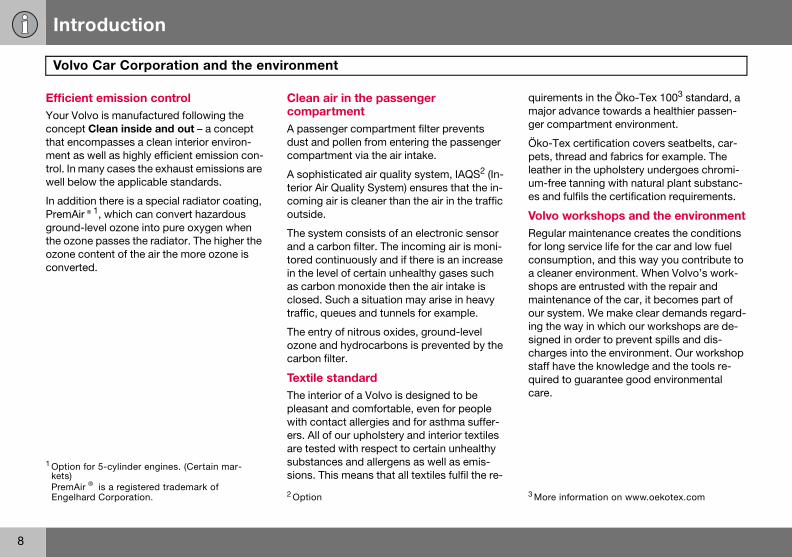
quirements in the Öko-Tex 1003 standard, a major advance towards a healthier passen-ger compartment environment.
Öko-Tex certification covers seatbelts, car-pets, thread and fabrics for example. The leather in the upholstery undergoes chromi-um-free tanning with natural plant substanc-es and fulfils the certification requirements.
Volvo workshops and the environmentRegular maintenance creates the conditions for long service life for the car and low fuel consumption, and this way you contribute to a cleaner environment. When Volvo’s work-shops are entrusted with the repair and maintenance of the car, it becomes part of our system. We make clear demands regard-ing the way in which our workshops are de-signed in order to prevent spills and dis-charges into the environment. Our workshop staff have the knowledge and the tools re-quired to guarantee good environmental care.
1 Option kets) PremAirEngelha 3 More information on www.oekotex.com
Car Corporation and the environment
t emission control lvo is manufactured following the Clean inside and out – a concept ompasses a clean interior environ- well as highly efficient emission con-any cases the exhaust emissions are w the applicable standards.
on there is a special radiator coating, ®1, which can convert hazardous level ozone into pure oxygen when e passes the radiator. The higher the
ontent of the air the more ozone is d.
Clean air in the passenger compartmentA passenger compartment filter prevents dust and pollen from entering the passenger compartment via the air intake.
A sophisticated air quality system, IAQS2 (In-terior Air Quality System) ensures that the in-coming air is cleaner than the air in the traffic outside.
The system consists of an electronic sensor and a carbon filter. The incoming air is moni-tored continuously and if there is an increase in the level of certain unhealthy gases such as carbon monoxide then the air intake is closed. Such a situation may arise in heavy traffic, queues and tunnels for example.
The entry of nitrous oxides, ground-level ozone and hydrocarbons is prevented by the carbon filter.
Textile standardThe interior of a Volvo is designed to be pleasant and comfortable, even for people with contact allergies and for asthma suffer-ers. All of our upholstery and interior textiles are tested with respect to certain unhealthy substances and allergens as well as emis-sions. This means that all textiles fulfil the re-
for 5-cylinder engines. (Certain mar-
® is a registered trademark of rd Corporation. 2 Option

Introduction
9
ReducYou canfor examchasingby serviing to th
The follofor the e
• DecreECO
• A rooanceconsafter
• RemoThe gcons
• If theheateing frtion a
• Drive• Drive
possspeecons
• Easeator oents.
ing environmental impact help reduce environmental impact, ple, by driving economically, by pur-
eco-labelled car care products and cing and maintaining the car accord-e instructions in the owner’s manual.
wing hints will help you to do your bit nvironment:
ase fuel consumption by choosing tyre pressure, see page 148.f load and ski box increase air resist-, leading to significantly higher fuel umption. Remove them immediately use.ve unnecessary items from the car. reater the load the higher the fuel
umption. car is equipped with an engine block r use it for a few hours before start-om cold. This reduces fuel consump-nd exhaust emissions. gently and avoid braking too hard. in the highest gear ible. Low engine ds result in lower fuel umption. back on the acceler-n downhill gradi-
• Use engine braking to slow down.• Avoid idling. Take consideration of local
regulations. Switch off the engine in traffic queues.
• Always dispose of envi-ronmentally hazardous waste, such as batteries and oils, in an environ-mentally safe manner. If uncertain about disposal, consult an authorised Volvo workshop for advice.
• Service your car regularly.These hints will help you reduce fuel con-sumption without increasing travel time or lessening the enjoyment of driving. Apart from being kind to your car, you’ll be saving money - and the Earth’s resources.

10
Seatbelts .................................................................................................. 12Airbag system .......................................................................................... 15Airbags (SRS) ........................................................................................... 16Activating/deactivating the airbag (SRS) .................................................. 19Side airbags (SIPS bags) .........................................................................21Inflatable Curtain (IC) ...............................................................................23WHIPS ......................................................................................................24When the systems deploy ........................................................................26Crash mode ..............................................................................................27Child safety ..............................................................................................28
01SAFETY

01 Safety
12
Seat01
Always
Tensionipositione
Heavy bquencesthat all p
Putting– Pull t
press"click
Releas– Press
belt rfully, hang
WARNING
Never modify or repair the belt yourself. Contact an authorised Volvo workshop. If the belt has been subjected to a major load, such as in a collision, the entire belt must be replaced. Some of the protective character-istics of the belt may have been lost, even if it appears to be undamaged. In addition, re-place the belt if it is worn or damaged. The new seatbelt must be type-approved and intended for installation in the same position as the replaced belt.
WARNING
The rear seat is designed for a maximum of two passengers.
belts
use a seatbelt
ng the hip strap. The belt must be d low down.
raking can have serious conse- if the seatbelts are not used. Ensure assengers use their seatbelts.
on a seatbelt:he belt out slowly and secure it by ing the buckle into the lock. A loud " indicates that the belt has locked.
ing the belt the red lock button and then let the
etract. If the belt does not retract feed it in by hand so that it does not loose.
The belt locks and cannot be withdrawn• if it is pulled out too quickly• during braking and acceleration• if the car leans heavily.It is important that the belt lies in contact against the body so it can provide maximum protection. Do not lean the backrest too far back. The belt is designed to protect in a nor-mal seating position.
Keep in mind the following:• do not use clips or anything else that can
prevent the belt from fitting properly• ensure the belt is not twisted or caught on
anything• the hip strap must be positioned low down
(not over the abdomen)• tension the hip strap over the lap by
pulling the diagonal shoulder belt as illustrated
WARNING
The seatbelts and airbags interact. If a seat-belt is not used or is used incorrectly, this may diminish the protection provided by the airbag in the event of a collision.
WARNING
Each belt is intended for one person only.

01 Safety
13
Seatbelts 01
Seatbe
An audioanyone The audminder iconsolelow spethe first
Child sereminde
Rear seThe seatwo sub
• Proviare b
Seatbelts and pregnancy
The seatbelt should always be worn during pregnancy. But it is crucial that it be worn in the correct way. The diagonal section should wrap over the shoulder then be routed be-tween the breasts and to the side of the ab-domen. The lap section should lay flat over the thighs and as low as possible under the abdomen. It must never be allowed to ride upward. Remove all slack from the belt and ensure that it fits close to the body. In addi-tion, check that there are no twists in the belt.
As a pregnancy progresses, pregnant drivers should adjust their seats and steering wheel such that they can easily maintain control of
lt reminder
signal and indicator lamp remind not wearing a seatbelt to use one. io reminder is speed-dependent. Re-ndicator lamps are located in the roof and combined instrument panel. At ed, the audio reminder will sound for six seconds.
ats are not covered by the seatbelt r system.
at tbelt reminder in the rear seat has functions:
des information on which seatbelts eing used in the rear seat. This is
shown on the information display. The message is automatically cleared after approx. 30 seconds or can be acknowl-edged manually by pressing the READ button.
• Provides a warning if one of the rear seatbelts is unfastened during a journey. This warning takes the form of a message on the information display along with the audio/visual signal. The warning ceases when the belt is re-fastened or can be acknowledged manually by pressing the READ button.
The message on the information display showing which belts are in use is always available. Press the READ button to see stored messages.
Certain marketsAn audio signal and indicator lamp remind the driver if not wearing a seatbelt to use one. At low speed, the audio reminder will sound for the first six seconds.

01 Safety
14
Seat01
the vehimust beals and they sholarge a dabdome
SeatbeAll the ssioners.tightensof a suffvides mpasseng
belts
cle as they drive (which means they able to easily operate the foot ped-steering wheel). Within this context, uld strive to position the seat with as istance as possible between their n and the steering wheel.
lt tensioner eatbelts are equipped with belt ten- A mechanism in the belt tensioner the belt around the body in the event iciently forceful collision. This pro-ore effective restraint by the belt for ers.
Seatbelt guide
The seatbelt guide is fitted on both the driver’s seat and passenger seat.
The seatbelt guide is an aid for providing bet-ter access to the seatbelt. When getting into and out of the rear seat the seatbelt is re-moved from the seatbelt guide and posi-tioned furthest back on the seatbelt bar.

01 Safety
15
Airbag system 01
Warnininstrum
The airbby the ssymbol luminatepositionapprox.system1
1 Includeand IC.
g symbol on the combined ent panel
ag system1 is continually monitored ystem’s control module. The warning on the combined instrument panel il-s when the ignition key is turned to I, II or III. The symbol goes out after seven seconds provided the airbag is fault-free.
As well as the warning sym-bol, a message may appear on the information display in some cases. If the warning symbol malfunctions, the warning triangle illuminates and the message SRS AIR-BAG SERVICE URGENT ap-pears in the information dis-play. Contact an authorised
Volvo workshop immediately.
s SRS and seatbelt tensioner, SIPS
WARNING
If the warning symbol for the airbag system remains on or illuminates while driving, it means that the airbag system is not func-tioning fully. The symbol can indicate a fault in the seatbelt buckle, SIPS, SRS or IC sys-tems. Contact an authorised Volvo work-shop immediately.

01 Safety
16
Airba01
Airbag
The car Restrainsupplemseatbeltof the stmarked
W
The sebelt is may diairbag
WARNING
To minimise the risk of injury if the airbag deploys, passengers must sit as upright as possible with their feet on the floor and back against the backrest. Seatbelts must be secured.
WARNING
Never place a child in a child seat or on a booster cushion in the front seat if the air-bag (SRS) is activated1.Never allow a child to stand or sit in front of the front passenger seat. No one shorter than 140 cm should ever sit in the front pas-senger seat if the airbag (SRS) is activated.Failure to follow the advice given above can endanger the life of the child.
1 For information on activated/deactivated air-bag (SRS) see page 19.
gs (SRS)
(SRS) on the driver’s side
has an SRS airbag (Supplemental t System) in the steering wheel to ent the protection afforded by the
. This airbag is fitted into the centre eering wheel. The steering wheel is SRS AIRBAG.
Passenger airbag (SRS)
The car has an SRS airbag (Supplemental Restraint System) to supplement the protec-tion afforded by the seatbelt. The passenger airbag1 is fitted behind a panel above the glovebox. This panel is marked SRS AIRBAG.
ARNING
atbelts and airbags interact. If a seat-not used or is used incorrectly, this minish the protection provided by the in the event of a collision.
1 Not all cars have a passenger airbag (SRS). This can be unselected when the car is or-dered.

01 Safety
17
Airbags (SRS) 01
SRS sy
SRS sys
The sysA sufficisors andgas. To flates wsmoke epletely ninflationwithin te
WARNING
Any repair must only be performed by an authorised Volvo workshop. Any interference in the SRS system could cause malfunction and result in serious per-sonal injury.
stem
tem, left-hand drive.
tem consists of airbags and sensors. ently violent collision trips the sen- the airbag(s) are inflated with hot
cushion the impact, the airbag de-hen compressed. When this occurs, scapes into the car. This is com-ormal. The entire process, including and deflation of the airbag, occurs nths of a second.
SRS system, right-hand drive.
NOTE
The sensors react differently depending on the course of the collision and whether or not the seatbelts on the driver and passen-ger side are used. It is therefore possible that only one (or none) of the airbags may inflate in a collision. The SRS system sens-es the force of the collision on the car and adapts accordingly so that one or more air-bags are deployed.
NOTE
The airbags have a function whereby their capacities are adapted to the collision force to which the car is subjected.

01 Safety
18
Airba01
Locationdrive and
W
Never steeringlovebObjecttionedBAG parea af
gs (SRS)
of the passenger airbag in left-hand right-hand drive cars
ARNING
interfere with SRS components in the g wheel or the panel above the ox.s and accessories must not be posi- or glued on or near the SRS AIR-anel (above the glovebox) or in the fected by a deployed airbag.
01 Safety
19
ing/deactivating the airbag (SRS) 01
PACOS
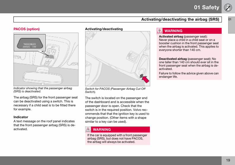
Indicator(SRS) is
The airbcan be dnecessafor exam
IndicatA text mthat the activate
WARNING
Activated airbag (passenger seat): Never place a child in a child seat or on a booster cushion in the front passenger seat when the airbag is activated. This applies to everyone shorter than 140 cm.
Deactivated airbag (passenger seat): No one taller than 140 cm should ever sit in the front passenger seat when the airbag is de-activated.Failure to follow the advice given above can endanger life.
Activat
(option)
showing that the passenger airbag deactivated.
ag (SRS) for the front passenger seat eactivated using a switch. This is ry if a child seat is to be fitted there ple.
oressage on the roof panel indicates front passenger airbag (SRS) is de-d.
Activating/deactivating
Switch for PACOS (Passenger Airbag Cut Off Switch).
The switch is located on the passenger end of the dashboard and is accessible when the passenger door is open. Check that the switch is in the required position. Volvo rec-ommends that that the ignition key is used to change position. (Other items with a shape similar to a key can be used).
WARNING
If the car is equipped with a front passenger airbag (SRS), but does not have PACOS, the airbag will always be activated.

01 Safety
20
Activ01
Switch
Switch fo
ON = Aiin this pcan sit inever chcushion
ating/deactivating the airbag (SRS)
position
r SRS in ON position.
rbag (SRS) activated. With the switch osition, persons taller than 140 cm n the front passenger seat, although ildren in a child seat or on a booster
.
Switch for SRS in OFF position.
OFF = Airbag (SRS) deactivated. With the switch in this position, children in a child seat or on a booster cushion can sit in the front passenger seat, although never persons tall-er than 140 cm.
WARNING
Do not allow anyone to sit in the front pas-senger seat if the text message in the roof panel indicates that the airbag (SRS) is de-activated and if the warning symbol for the airbag system is also displayed on the com-bined instrument panel. This indicates that there has been a severe malfunction. Con-tact an authorised Volvo workshop immedi-ately.

01 Safety
21
Side airbags (SIPS bags) 01
Side ai
Side airb
A large ptransfertion Sysroof andThe sidesenger san impobags are
Child seats and side airbagsThe side airbag does not diminish the protec-tion provided by the car to children seated in a child seat or on a booster cushion.
A child seat or booster cushion can be placed on the front passenger seat provided that the car does not have an activated1 pas-senger airbag.
WARNING
Do not put objects in the area between the outside of the seat and the door panel, since this area is required by the side air-bag.
WARNING
Use only Volvo genuine car seat covers, or seat covers approved by Volvo. Other seat covers may impede the operation of the side airbags.
1 For information on activated/deactivated air-bag (SRS) see page 19
rbags – SIPS bags
ag locations.
roportion of the collision force is red by the SIPS (Side Impact Protec-tem) to beams, pillars, the floor, the other structural parts of the body. airbags at the driver’s and front pas-eats protect the chest area and are rtant part of the SIPS. The side air- located in the front seat backrests.
Inflated side airbag.
WARNING
Side airbags are a supplement to the SIPS system. Always use a seatbelt.
WARNING
Any repair must only be performed by an authorised Volvo workshop.Any interference in the SIPS system could cause malfunction and result in serious per-sonal injury.

01 Safety
22
Side 01
SIPS b
Driver’s
The SIPbags ansion tripinflated.cupant aions theside airbside of t
airbags (SIPS bags)
ags
side
S bag system consists of side air-d sensors. A sufficiently violent colli-s the sensors and the side airbag is The airbag inflates between the oc-nd the door panel and thereby cush-
initial impact while deflating. The ag is only normally deployed on the he collision.
Passenger side
01 Safety
23
Inflatable Curtain (IC) 01
Proper
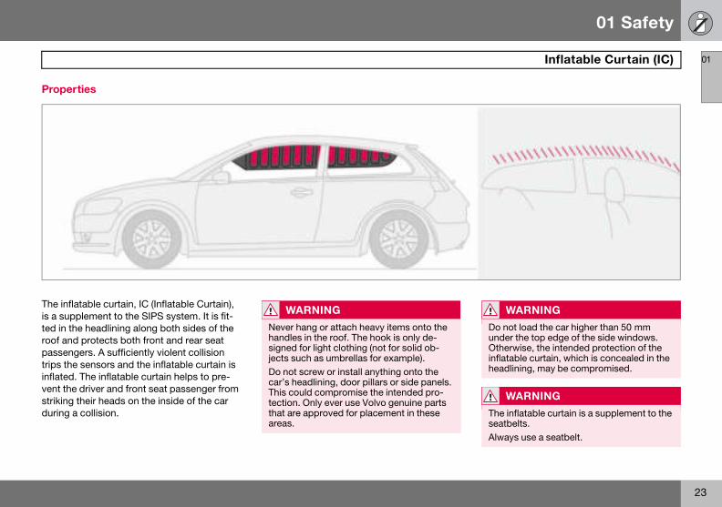
The inflais a supted in throof andpassengtrips theinflated.vent thestriking during a
WARNING
Do not load the car higher than 50 mm under the top edge of the side windows. Otherwise, the intended protection of the inflatable curtain, which is concealed in the headlining, may be compromised.
WARNING
The inflatable curtain is a supplement to the seatbelts.Always use a seatbelt.
ties
table curtain, IC (Inflatable Curtain), plement to the SIPS system. It is fit-e headlining along both sides of the protects both front and rear seat ers. A sufficiently violent collision sensors and the inflatable curtain is The inflatable curtain helps to pre- driver and front seat passenger from their heads on the inside of the car collision.
WARNING
Never hang or attach heavy items onto the handles in the roof. The hook is only de-signed for light clothing (not for solid ob-jects such as umbrellas for example).Do not screw or install anything onto the car’s headlining, door pillars or side panels. This could compromise the intended pro-tection. Only ever use Volvo genuine parts that are approved for placement in these areas.

01 Safety
24
WHIP01
ProtecWHIPS
The whiconsistsspeciallyfront seaend collthe collivehicle a
HIPS system and child seats/ooster cushions he WHIPS system does not diminish the rotection provided by the car to children eated in a child seat or on a booster cush-on.
orrect seating positionor the best possible protection, the driver nd front seat passenger should sit in the entre of the seat with as little space as pos-ible between the head and the head re-traint.
W
The Wseatbe
S
tion against whiplash injury –
plash protection system (WHIPS) of energy absorbing backrests and designed head restraints for the ts. The system is actuated by a rear-
ision, where the angle and speed of sion, and the nature of the colliding ll have an influence.
Properties of the seatWhen the WHIPS system is deployed, the front seat backrests are lowered backward to alter the seating position of the driver and front seat passenger. This reduces the risk of whiplash injury.
WbTpsi
CFacss
ARNING
HIPS system is a supplement to the lts. Always use a seatbelt.
WARNING
Never modify or repair the seat or WHIPS system yourself. Contact an authorised Volvo workshop.
01 Safety
25
WHIPS 01
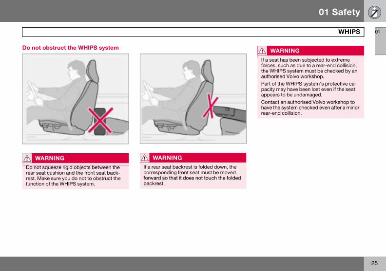
Do not
W
Do notrear serest. Mfunctio
WARNING
If a seat has been subjected to extreme forces, such as due to a rear-end collision, the WHIPS system must be checked by an authorised Volvo workshop.Part of the WHIPS system’s protective ca-pacity may have been lost even if the seat appears to be undamaged.Contact an authorised Volvo workshop to have the system checked even after a minor rear-end collision.
obstruct the WHIPS system
ARNING
squeeze rigid objects between the at cushion and the front seat back-ake sure you do not to obstruct the n of the WHIPS system.
WARNING
If a rear seat backrest is folded down, the corresponding front seat must be moved forward so that it does not touch the folded backrest.

01 Safety
26
When01
If the airlowing i
• HaveVolvoploye
• Let acomp
• Alwa
Syste
Seatbe nd/or overturning.Airbags
Side ai
Inflatab
Whipla
1The bo ctors such as the rigidity and weight of the object hit, the red.
NO
The SRtems asion
WARNING
Never drive with deployed airbags. They can make steering difficult. Other safety systems may also be damaged. The smoke and dust created when the airbags are de-ployed can cause skin and eye irritation/in-jury after intensive exposure. In case of irritation, wash with cold water. The rapid deployment sequence and airbag fabric may cause friction and skin burns.
the systems deploy
bags have been deployed, the fol-s recommended:
the car transported to an authorised workshop.Do not drive with de-d airbags.n authorised Volvo workshop replace onents in the car’s safety system.
ys contact a doctor.
m Triggered
lt tensioner In a frontal collision and/or side-impact accident a (SRS) In a frontal collision1.
rbags (SIPS) In a side-impact accident1.le Curtain IC In a side-impact accident1.sh protection WHIPS In a rear-end collision.
dywork of the car could be greatly deformed in a collision even without airbag deployment. A number of faspeed of the car, the angle of the collision etc. affects how the different safety systems of the car are trigge
TE
S, SIPS, IC and belt tensioner sys-re deployed only once during a colli-
WARNING
The airbag system’s control module is lo-cated in the centre console. If the centre console is drenched with water or other liq-uid, disconnect the battery cables. Do not attempt to start the car since the airbags may deploy. Have the car transported to an authorised Volvo workshop.

01 Safety
27
Crash mode 01
Driving
If the caCRASHon the inthe car hmode iswhen ththe car’slines, seor the b
AttempFirst, chcar. The
WARNING
Never, under any circumstances, attempt to restart the car if it smells of fuel when the crash mode message is displayed. Leave the car at once.
WARNING
If the car is in crash mode it must not be towed. It must be transported to an author-ised Volvo workshop.
after a collision
r is involved in a collision, the text MODE - SEE MANUAL may appear formation display. This means that as reduced functionality. Crash
a protective state that is enforced e collision may have damaged any of vital functions, such as the fuel nsors for one of the safety systems, rake system.
ting to start the careck that no fuel is leaking from the re must be no smell of fuel either.
If everything seems normal and you have checked for indications of fuel leakage, you may attempt to start the car.
Firstly, remove the ignition key and then rein-sert it. The car’s electronics will then try to re-set themselves to normal mode. Then try to start the car. If CRASH MODE is still shown on the display then the car must not be driv-en or towed. Even if the car appears to be driveable, hidden damage may make the car impossible to control once moving.
Moving the carIf NORMAL MODE is shown after crash mode has been reset, the car can be moved carefully out of a dangerous position. Do not move the car further than necessary.
WARNING
Never attempt to repair your car or reset the electronics yourself if the car has been in crash mode. This could result in personal injury or the car not functioning as normal. Always allow an authorised Volvo workshop to check and restore the car to normal mode after CRASH MODE has been dis-played.

01 Safety
28
Child01
Childresafely
The poschoice oweight apage 30
Childrencorrectlchild to
Volvo’s signed fequipmepoints ationed a
You ma
• a chilfront seng
• a rearuses
Location of airbag decal in door opening on front passenger side
NO
Regulachildretry. Ch
1 For infobag (SR
WARNING
Never place a child in a child seat or on a booster cushion in the front seat if the air-bag (SRS) is activated1. Failure to follow this advice can endanger the life of the child.
1 For information on activated/deactivated air-bag (SRS), see page 19.
safety
n should sit comfortably and
ition of a child in the car and the f equipment is dictated by the child’s nd size. For more information, see .
of all ages and sizes must always sit y secured in the car. Never allow a sit on the knee of a passenger.
own child safety equipment is de-or your car. Use Volvo genuine nt to best ensure that the mounting
nd attachments are correctly posi-nd are sufficiently strong.
y place:
d seat or booster cushion on the passenger seat, provided the pas-er airbag is not activated1.-facing child seat in the rear seat that the back of the front seat as support.
Child seats and airbags
Child seats and airbags are not compatible.
Always place a child in the rear seat if the passenger airbag is activated1. A child in a child seat on the front passenger seat may suffer serious injury if the airbag deploys.
TE
tions regarding the placement of n in cars vary from country to coun-eck what does apply.
rmation on activated/deactivated air-S) see page 19.
WARNING
Persons shorter than 140 cm may only sit in the front passenger seat if the passenger airbag is deactivated.

01 Safety
29
Child safety 01
Decal loc
ated on instrument panel end face. Decal located on instrument panel end face (Australia only).
01 Safety
30
Child01
Placem
Weigh
<10 kg(0–9 m
with d
9–18 kg(9–36 m
with d
15–36 k(3–12 y
1 For info2 L: Suita ,
limited,3 To insta ints
installed
safety
ent of children in the car
t/age Front seat1 Rear seat
onths)Rear-facing child seat, secured with seatbelt and straps. Use a protective cushion between the child seat and the dashboard. L2: Type approval no. E5 03135
Rear-facing child seat, secured seatbelt, support legs, straps anattachment eye3. L2: Type approval no. E5 03135
onths)Rear-facing child seat, secured with seatbelt and straps. Use a protective cushion between the child seat and the dashboard.L2: Type approval no. E5 03135
Rear-facing child seat, secured seatbelt, support legs, straps anattachment eye.3
L2: Type approval no. E5 03135
gears)
Booster cushion with or without backrest.L2: Type approval no. E5 03139
Booster cushion with or withoutbackrest.L2: Type approval no. E5 03139
rmation on activating/deactivating the airbag (SRS), see page 19.
ble for certain child seats as listed in the specified type approval. Child seats can be vehicle-specific semi-universal or universal.
ll a rear-facing child seat in the rear seat, contact an authorised Volvo dealer to have the mounting po.

01 Safety
31
Child safety 01
Fitting Volvo hasigned f
When uson the mting inst
• Do noto therails oedge
• Allowagaincars wthe a
ISOFIX fixture system for child seats (option)
The outer rear seats have ISOFIX mounting points for child seats. Contact a Volvo dealer for further information on child safety equip-ment.
W
Boostebraceson the must nseatbeDo notseat to
a child seat s child safety products that are de-
or and tested by Volvo.
ing other products that are available arket, it is important to read the fit-
ructions included with the product.
t attach the straps for the child seat horizontal adjustment bar, springs, r beams under the seat. Sharp
s can damage the straps. the back of the child seat to rest st the dashboard. This applies to ithout a passenger airbag, or where
irbag is deactivated.
ARNING
r cushions/child seats with steel or some other design that could rest seatbelt buckle’s opening button ot be used, as they could cause the lt buckle to open accidentally. allow the upper section of the child rest against the windscreen.
WARNING
Never place the child seat in the front seat if the car is equipped with an activated1 front passenger airbag. If problems arise when fitting child safety products, contact the manufacturer for clearer instructions.
1For information on activated/deactivated airbag (SRS), see page 19.

32
Overview, left-hand drive car ...................................................................34Overview, right-hand drive car .................................................................36Driver’s door control panel .......................................................................38Combined instrument panel .....................................................................39Indicator and warning symbols ................................................................40Information display ...................................................................................43Electrical socket and switch, centre console ...........................................45Lighting panel ...........................................................................................46Left-hand stalk switch ..............................................................................48Right-hand stalk switch ...........................................................................50Cruise control (option) ..............................................................................52Steering wheel keypad (option) ................................................................54Steering wheel adjustment, hazard warning flashers ..............................55Parking brake, electrical socket ...............................................................56Power windows ........................................................................................57Rearview and door mirrors .......................................................................59Power sunroof (option) .............................................................................62Personal preferences ...............................................................................64

02INSTRUMENTS AND CONTROLS
02 Instruments and controls
34
Over
02
view, left-hand drive car

02 Instruments and controls
35
Overview, left-hand drive car
02
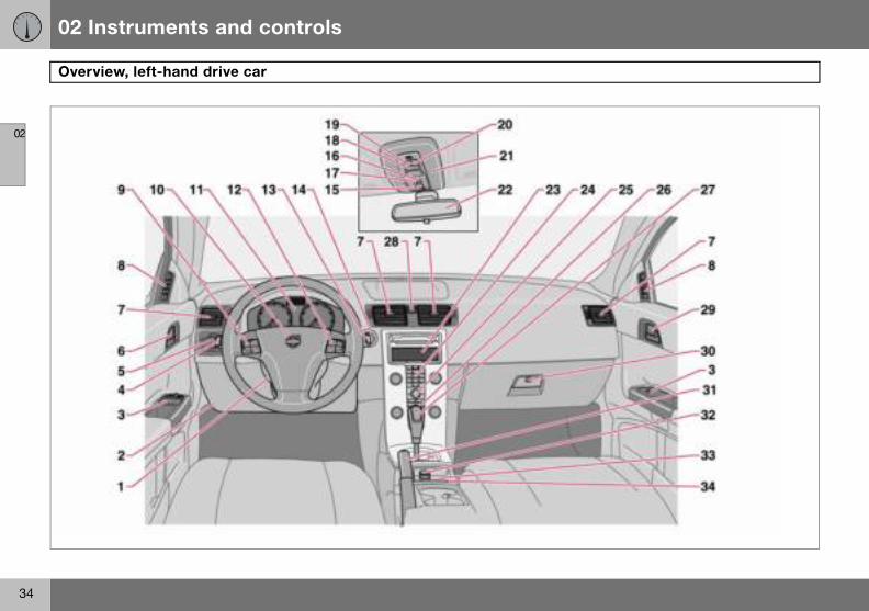
1. Stee2. Bon3. Con4. Dire5. Ligh6. Doo7. Air v8. Air v9. Crui10.Horn11.Com12.Keyp13.Wind14. Ignit15.Sun16.No f17.Dea18. Inter19.Rea20.Rea21.Seat22. Inter23.Disp24. Infot25.Con
pref
hers
garette lighterion System, BLISuipment
ring wheel adjustmentnet releasetrol panelction indicators, main beam, trip computerting, fuel filler flap openerr handle, lock button.ents, dashboardent for side windowse control, airbagbined instrument panelad for infotainment systemscreen wipers, washer and headlamp washers
ion switchroof controlsunctionctivation of alarm detectors, deadlocksior lighting, switch
ding lamp, left-hand sideding lamp, right-hand sidebelt reminderior rearview mirrorlay for climate control and infotainment systemainment systemtrols for climate control, infotainment system and personal erences
26.Climate control27.Gear lever28.Hazard warning flas29.Door handle30.Glovebox31.Parking brake32.Electrical socket/ci33.Blind Spot Informat34.Switch, optional eq

02 Instruments and controls
36
Over
02
view, right-hand drive car

02 Instruments and controls
37
Overview, right-hand drive car
02
1. Swit2. Blind3. Elec4. Park5. Con6. Glov7. Doo8. Air v9. Air v10.Gea11.Clim12.Con
pref13. Infot14.Disp15. Inter16.Seat17. Inter18.Rea19.Rea20.No f21.Dea22.Sun23. Ignit24.Wind25.Crui
nt panel
ment systemhersuttonlap opener, main beam, trip computer
stment
ch, optional equipment Spot Information System, BLIS
trical socket, cigarette lightering braketrol paneleboxr handleent for side windowents, dashboardr leverate controltrols for climate control, infotainment system and personal erencesainment systemlay for climate control and infotainment systemior rearview mirrorbelt reminderior lighting, switch
ding lamp, left-hand sideding lamp, right-hand sideunctionctivation of alarm detectors, deadlocksroof controlsion switchscreen wipers and washer, headlamp washers
se control
26.Combined instrume27.Horn, airbag28.Keypad for infotain29.Hazard warning flas30.Door handle, lock b31.Lighting, fuel filler f32.Direction indicators33.Bonnet release34.Steering wheel adju
02 Instruments and controls
38
Drive
02
Driver’
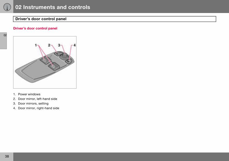
1. Pow2. Doo3. Doo4. Doo
r’s door control panel
s door control panel
er windowsr mirror, left-hand sider mirrors, settingr mirror, right-hand side

02 Instruments and controls
39
Combined instrument panel
02
1. Spee2. Dire3. War4. Infor
pressagetimebetwsymwarnperahighstati
5. Infor6. Dire
.Knob for clock – Turn the knob to adjust the time.
.Temperature gauge – Displays the tem-perature of the engine cooling system. A message will appear on the display if the temperature becomes too high and the gauge goes into the red zone. Bear in mind that extra lights placed in front of the air intake, for example, reduce the cooling capacity at high outside temperatures and high engine loads.
. Indicator and warning symbols.
dometer.ction indicators, left.ning symbol.mation display – The display ents information or warning mes-s, outside temperature and the . When the outside temperature is een +2 �C and –5 �C, a snowflake
bol appears on the display. This s of icy roads. The outside tem-ture gauge may show a slightly reading after the car has been onary. mation symbol.ction indicator, right.
7. Tachometer – Indicates engine speed in thousands of revolutions per minute (rpm).
8. Indicator and information symbols.9. Fuel gauge.10.Button for trip meter – Used to measure
short distances. Short presses on the button switches between the two trip meters T1 and T2. A long press (more than 2 seconds) resets an active trip meter to zero.
11.Display – Display for automatic gear position, rain sensor, odometer, trip meter and cruise control.
12.Main beam indicator.
13
14
15
02 Instruments and controls
40
Indic
02
Functio
All indicwhen thbefore sbols arethe symbrake sybrake is
pending
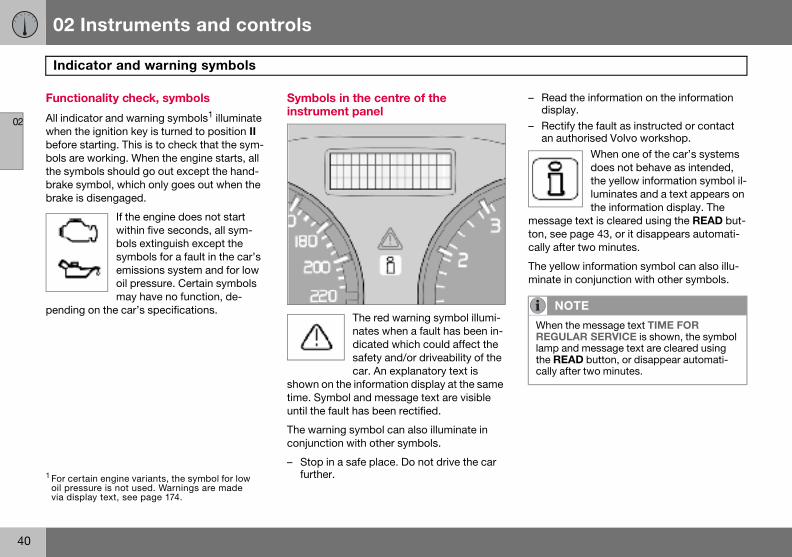
– Read the information on the information display.
– Rectify the fault as instructed or contact an authorised Volvo workshop.
When one of the car’s systems does not behave as intended, the yellow information symbol il-luminates and a text appears on the information display. The
message text is cleared using the READ but-ton, see page 43, or it disappears automati-cally after two minutes.
The yellow information symbol can also illu-minate in conjunction with other symbols.
1 For certoil presvia disp
NOTE
When the message text TIME FOR REGULAR SERVICE is shown, the symbol lamp and message text are cleared using the READ button, or disappear automati-cally after two minutes.
ator and warning symbols
nality check, symbols
ator and warning symbols1 illuminate e ignition key is turned to position II tarting. This is to check that the sym- working. When the engine starts, all bols should go out except the hand-mbol, which only goes out when the disengaged.
If the engine does not start within five seconds, all sym-bols extinguish except the symbols for a fault in the car’s emissions system and for low oil pressure. Certain symbols may have no function, de-
on the car’s specifications.
Symbols in the centre of the instrument panel
The red warning symbol illumi-nates when a fault has been in-dicated which could affect the safety and/or driveability of the car. An explanatory text is
shown on the information display at the same time. Symbol and message text are visible until the fault has been rectified.
The warning symbol can also illuminate in conjunction with other symbols.
– Stop in a safe place. Do not drive the car further.ain engine variants, the symbol for low
sure is not used. Warnings are made lay text, see page 174.

02 Instruments and controls
41
Indicator and warning symbols
02
Indicat
1. Fault
2. ABS
– Stop the e
– Resta
Indicator symbols – right-hand side
1. Indicator symbol for trailerThis symbol flashes when the di-rection indicators are used and the trailer is connected. If the symbol does not flash then one
of the lamps on the trailer or the car is faulty.
or symbols – left-hand side
in car’s emissions system Drive to an authorised Volvo workshop to have the system checked.
fault If this symbol illuminates then the system is not working. The car’s regular brake system continues to work, but without the ABS function.
the car in a safe place and turn off ngine.rt the engine.
– Drive to an authorised Volvo workshop to have the ABS checked if the symbol re-mains lit.
3. Rear fog lampThis symbol is lit when the rear fog lamp is on.
4. Stability system STC or DSTC For information on the system’s functions and symbols, see page 121.
5. No function
6. Engine preheater (diesel) This symbol illuminates during engine preheating. Preheating occurs when the temperature is below –2 �C. The car can be started once the symbol
goes out.
7. Low level in fuel tank This symbol illuminates when there are approximately 8 litres of usable fuel left in a petrol-en-gined car, or approximately 7 litres in a diesel-engined car.

02 Instruments and controls
42
Indic
02
2. Park
3. Airba
systemsVolvo w
4. Low
gine oil bol lighttact an a
– Stop the car in a safe place and turn off the engine.
– Restart the engine.– If both symbols extinguish, continue driv-
ing.– If the symbols remain on, check the level
in the brake fluid reservoir. See page 177.– If the brake fluid level is normal but the
symbols are still lit, the car can be driven, with great care, to an authorised Volvo workshop to have the brake system checked.
– If the level in the reservoir is below MIN, the car should not be driven any further. Have the car transported to an authorised Volvo workshop to have the brake system checked.
NO
The lamhard th
1 For certoil presvia disp
WARNING
If the BRAKE and ABS symbols are illumi-nated at the same time, there is a risk that the rear end will skid during heavy braking.
ator and warning symbols
ing brake applied The lamp illuminates when the parking brake is applied. Always pull the parking brake lever to the end position.
gs – SRSIf this symbol remains on or illu-minates while driving, it means a fault has been detected in the seatbelt buckle, SRS, SIPS, or IC
. Drive immediately to an authorised orkshop to have the system checked.
oil pressure1
If this symbol illuminates during driving then the engine’s oil pres-sure is too low. Stop the engine immediately and check the en-
level, top up if necessary. If the sym-s up and the oil level is normal, con-uthorised Volvo workshop.
5. Seatbelt reminderThis symbol lights if someone in a front seat has not put on their seatbelt or if someone in a rear seat has taken off their seatbelt.
6. Alternator not chargingIf this symbol illuminates while driving, a fault has occurred in the electrical system. Contact an authorised Volvo workshop.
7. Fault in brake systemIf this symbol lights, the brake fluid level may be too low.
– Stop the car in a safe place and check the level in the brake fluid reservoir, see page 177. If the level in the reservoir is below MIN, the car should not be driven any further. Have the car transported to an authorised Volvo workshop to have the brake system checked.
If the BRAKE and ABS symbols illuminate at the same time, there may be a fault in the brake force distribution system.
TE
p illuminates irrespective of how e parking brake is applied.
ain engine variants, the symbol for low sure is not used. Warnings are made lay text, see page 174.

02 Instruments and controls
43
Information display
02
Remind
If one ofis not prminded
Low sp
DRIVEROPEN, ocar as sthe open
High sp
graph a
Tailgat
1 Only ca
er – doors not closed
the doors, the bonnet1 or the tailgate operly closed, the driver will be re-of this.
eed If the car is travelling at a speed lower than approx. 7 km/h, the information symbol will illuminate and one of the following texts will be shown on the display:
DOOR OPEN, PASSENGER DOOR r ENGINE HOOD OPEN. Stop the
oon as it is safe to do so and close door or bonnet.
eedIf the car is moving faster than approx. 7 km/h, the symbol illu-minates and one of the texts in-dicated in the previous para-
ppears in the display.
e reminderIf the tailgate is open, this infor-mation symbol will illuminate and TAILGATE OPEN will appear on the display.
Messages
When a warning or indicator symbol illumi-nates, a message appears on the information display.
– Press the READ button (1).Switch between messages with the READ button. Error messages are stored in a mem-ory list until the fault is rectified.
rs with alarm.
NOTE
If a warning message appears while you are using the trip computer, the message must be read (press READ) before the previous activity can be resumed.

02 Instruments and controls
44
Infor
02Messa
STOP Serious risk of damage.
STOP Serious risk of damage.
SERVI p immediately.
SEE MSERVI p as soon as possible.
TIME F op. The timing is determined by the number of rvice and engine running time.
CHECK 00 km1. For information on checking the oil
SOOT 11.
STC/D m is reduced, see page 122 for more variants.
1Certai
mation display
ge Specification
SAFELY Stop the car in a safe manner and turn off the engine.
ENGINE Stop the car in a safe manner and turn off the engine.
CE URGENT Have the car checked by an authorised Volvo worksho
ANUAL Read the owner’s manual.
CE REQUIRED Have the car checked by an authorised Volvo worksho
OR REGULAR SERVICE Time for regular service at an authorised Volvo workshkilometres driven, number of months since the last se
OIL LEVEL Check the oil level. The message is shown every 10 0level, see page 175.
FILTER FULL SEE MANUAL Diesel particle filter requires regeneration, see page 1
STC SPIN CONTROL OFF The function of the stability and traction control syste
n engine variants

02 Instruments and controls
45
ocket and switch, centre console
02
12 V el
Electrica
The elecaccessoand cooFor the key mus
W
Alwaysthe soc
Electrical s
ectrical socket
l socket, BLIS and extra equipment
trical socket can be used for 12 V ries, such as mobile phone chargers lers. The maximum current is 10 A. socket to supply current, the ignition t be in at least position I.
Cigarette lighter (option) Activate the lighter by pushing in the button. The button pops out when the lighter is hot. Pull out the lighter and light a cigarette on the heated coils.
Extra equipmentSpace for an extra switch for retrofitted equipment.
ARNING
leave the plug in the socket when ket is not in use.

02 Instruments and controls
46
Light
02
cept when the headlamp control (2) is in the centre position. If necessary, the automatic dipped beam can be deactivated by an au-thorised Volvo workshop.
Automatic dipped beam, main beam – Turn the ignition key to position II.– Dipped beam is activated by means of
turning the headlamp control (2) clockwise to the end position.
– Main beam is activated by means of mov-ing the left-hand stalk switch towards the steering wheel to the end position and releasing it, see page 48.
The lamps are switched off automatically when the ignition key is turned to position I or 0.
Instrument lighting The instrument lighting is switched on when the ignition key is in position II and the head-lamp control (2) is in one of the end positions. The lighting is automatically dimmed during the day and can be controlled manually at night.
– Roll the control up or down (3) for brighter or dimmer lighting.
Posi-tion
ing panel
Headlamp levellingThe load in the car changes the vertical align-ment of the headlamp beam, which could dazzle oncoming motorists. Avoid this by ad-justing the height of the beam.
– Turn the ignition key to position II.– Turn the headlamp control (2) to one of the
end positions.– Roll the control (1) up or down respective-
ly to raise or lower beam alignment.Cars with Bi-Xenon headlamps1 have auto-matic headlamp levelling, so there is no control (1).
Position/parking lamps Position/parking lamps can be switched on irrespective of ignition key position.
– Turn the headlamp control (2) to the centre position.
When the ignition key is in position II the po-sition/parking lamps and number plate light-ing are always on.
Headlamps
Automatic dipped beam (certain countries) Dipped beam comes on automatically when the ignition key is turned to position II, ex-
Specification
Automatic/deactivated dipped beam. Only main beam flash.Position/parking lamps
Automatic dipped beam. Main beam and main beam flash work in this position.
1 Option.

02 Instruments and controls
47
Lighting panel
02
EnhancTo faciliclock anilluminathe key The displocked.
Fog lam
Front foThe fronalong wlamps/p
– PressThe lighthe fron
Rear foThe rearwith the
– PressThe rearcombine
NO
Regulacountr
ed display lightingtate reading the odometer, trip meter, d outside temperature gauge, these
te when the car is unlocked and when is removed from the ignition switch. lays extinguish when the car is
ps
g lamps (option)t fog lamps can be switched on ith the headlamps or the position arking lamps.
the button (4).t in the button (4) illuminates when t fog lamps are switched on.
g lamp fog lamp can only be switched on headlamps or the front fog lamps.
the button (6). fog lamp indicator symbol on the d instrument panel and the light in
the button (6) illuminate when the rear fog lamp is switched on.
Fuel filler flapPress button (5) to open the fuel filler flap when the car is unlocked, see page 110.
TE
tions for use of fog lamps vary from y to country.

02 Instruments and controls
48
Left-
02
Stalk s
1. Shor2. Con
indic3. Main4. Swit
hom
Directi
Continu– Move
positThe staland is mly by ste
Move the stalk switch towards the steer-ing wheel to the end position (4) and re-lease.Get out of the car and lock the door.
hand stalk switch
witch positions
t flash sequence, direction indicatorstinuous flash sequence, direction ators beam flashching, main and dipped beam, and e safe lighting
on indicators
ous flash sequence the stalk switch up or down to end
ion (2).k switch remains in its end position oved back manually, or automatical-ering wheel movement.
Short flash sequence– Move the stalk switch up or down to
position (1) and release.The direction indicators flash three times and the stalk switch returns to its home position.
Switching, main and dipped beam The ignition key must be in position II for main beam to be switched on.
– Turn the headlamp control clockwise to the end position, see page 46.
– Move the stalk switch towards the steer-ing wheel to the end position (4) and re-lease.
Main beam flash – Move the stalk switch gently towards the
steering wheel to position (3).Main beam comes on until the stalk switch is released.
Home safe lighting Some of the exterior lighting can be kept switched on to work as home safe lighting af-ter the car has been locked. The standard delay is 30 seconds1, but can be changed to 60 or 90 seconds, see page 65.
– Remove the key from the ignition switch.
–
–
1 Factory settings.

02 Instruments and controls
49
Left-hand stalk switch
02
Trip co
ControTo scrolturn thesteps. Cing poin
AVERAGE The average fuel consumption since the last reset (RESET). The average fuel consump-tion is stored when the ignition is switched off and remains until the function is reset. Re-set using the RESET button (C).
KILOMETRES TO EMPTY TANKThe range to empty is calculated based on the average fuel consumption over the last 30 km. When the range to empty is shorter than 20 km then "----" is shown on the display.
Resetting– Select AVERAGE SPEED or AVERAGE
– Press and hold the RESET button (C) for at least five seconds to reset the average speed and average consumption at the same time.
NO
If a waare usimust bpressinthe trip
NOTE
There may be a slight error in the reading if a fuel-driven heater is used.
NOTE
There may be a slight error in the reading if fuel consumption is changed due to a change in driving style or if a fuel-driven heater is used for example.
mputer (option)
lsl through trip computer information thumbwheel (B) either up or down in ontinue turning to return to the start-t.
FunctionsThe trip computer displays the following in-formation:
• AVERAGE SPEED
• ACTUAL SPEED MPH1
• INSTANTANEOUS
• AVERAGE
• KILOMETRES TO EMPTY TANK• STC/DSTC, see page 121
AVERAGE SPEEDWhen the ignition is switched off, the average speed is stored and used as the basis of the new value when you continue driving. Reset using the RESET button (C).
ACTUAL SPEED1
Current speed is displayed in mph.
INSTANTANEOUSCurrent fuel consumption is calculated every second. The information on the display is up-dated every couple of seconds. When the car is stationary, "---- " appears on the display. During the period for regeneration2 fuel con-sumption may increase, see page 111.
TE
rning message interrupts while you ng the trip computer, this message e acknowledged. Acknowledge by g the READ button (A) and revert to computer function.
1 Certain countries.2 Only applies to diesel cars with particle filter.

02 Instruments and controls
50
Righ
02
Windsc
A. Wind
B. Rain
C. Thum
D. Wipe
Windsc
High-pressure headlamp washing (option in certain markets)High-pressure headlamp washing consumes a large quantity of washer fluid. To save fluid, the headlamps are washed as follows:
Dipped beam selected with the switch on lighting panel:
The headlamps are washed the first time the windscreen is washed. Within the next ten minutes, they are washed every fifth wash cycle of the windscreen. In the event of a longer interval the headlamps are washed each time.
Parking/position lamps selected with the switch on the lighting panel:
• Bi-Xenon headlamps are only washed every fifth wash cycle irrespective of the time that elapses.
• Halogen headlamps are not washed.The switch on the lighting panel is in position 0:
• Bi-Xenon headlamps are only washed every fifth wash cycle irrespective of the time that elapses.
• Halogen headlamps are not washed.
t-hand stalk switch
reen wipers
screen and headlamp washers
sensor – On/Off
bwheel
r and washer, rear window
reen wipers offThe windscreen wipers are off when the stalk switch is in position 0.
Single sweepRaise the stalk switch to make a single sweep.
Intermittent wiping The delay between sweeps can be adjusted. Turn the thumbwheel (C) up for a shorter
interval between sweeps. Turn it down to in-crease the delay.
Continuous wipingThe wipers sweep at normal speed.
The wipers sweep at high speed.
Windscreen/headlamp washers Move the stalk switch toward the steering wheel to start the windscreen and headlamp washers. The wipers will make three more sweeps once the stalk switch is released.
IMPORTANT
Use plenty of washer fluid when the wipers are cleaning the windscreen. The wind-screen must be wet when the windscreen wipers are operating.

02 Instruments and controls
51
Right-hand stalk switch
02
Wiper aPress thwindowmakes sished. Tthree po
Intermit
– DeprNormal
– DeprNeutral:
– Func
Wiper –Engaginwipers adow wipready onmade.
The funcverse caised Vol
Activating the rain sensor:
– Press the button (B). A display symbol shows that the rain sensor is active.
To turn the rain sensor off, either:
– Press button (B)– Press the stalk switch downward to anoth-
er wiper program. If the stalk switch is raised, the rain sensor will remain active, the wipers make an extra sweep and then return to rain sensor mode when the stalk is released to position 0.
The rain sensor is automatically deactivated when the key is removed from the ignition switch or five minutes after the ignition is switched off.
ThumbwheelUse the thumbwheel to adjust the frequency of sweeps when intermittent wiping is select-ed, or the sensitivity to rain when the rain sensor is selected.
IMPORTANT
At an automatic car wash: Deactivate the rain sensor by pressing the button (B) while the ignition key is in position I or II. Other-wise, the windscreen wipers could start swiping and become damaged.
nd washer, rear window e stalk switch forward to initiate rear washing and wiping. The wiper blade everal sweeps once washing has fin-he control at the end of the stalk has sitions:
tent wiping:
ess the top of the switch.speed:
ess the bottom of the switch.
tion deactivated.
reversingg reverse gear while the windscreen re on initiates intermittent rear win-ing. If the rear window wiper is al- at normal speed, no change is
tion for intermittent wiping for re-n be deactivated. Contact an author-vo workshop.
Rain sensor (option)
The rain sensor automatically activates the windscreen wipers based on how much wa-ter it detects on the windscreen. The sensitiv-ity of the rain sensor can be adjusted using the thumbwheel (C).
Turn the thumbwheel clockwise for higher sensitivity and anticlockwise for lower sensi-tivity. (An extra sweep is made when the thumbwheel is turned clockwise.)
On/OffWhen activating the rain sensor, the ignition key must be in position I or II and the wind-screen wiper stalk switch must be in position 0.

02 Instruments and controls
52
Cruis
02
Activat
The conof the st
Setting
– Pressshow
– ToucCRUIinstru
Cruise cbelow 3
Temporary disengagement– Press 0 to disengage the cruise control
temporarily. CRUISE will be shown on the combined instrument panel. The speed set earlier is stored in the memory.
The cruise control is also temporarily disen-gaged when:
• the brake pedal or clutch pedal is de-pressed
• speed falls below 25–30 km/h when trav-elling uphill1
• the gear selector is moved to position N• wheel spin or wheel lock-up occurs• a temporary increase in speed lasts longer
than one minute.
e control (option)
ing
trols for cruise control are to the left eering wheel.
the desired speed:
the CRUISE button. CRUISE is n on the combined instrument panel.h + or — to lock the vehicle speed. SE-ON appears on the combined ment panel. ontrol cannot be engaged at speeds 0 km/h or above 200 km/h.
Increasing or decreasing speed
– Increase or decrease the locked speed by pressing and holding + or –. The speed of the car when the button is released is set as the new speed.
Pressing (less than half a second) + or – changes the speed 1 km/h or 1.6 km/h1.
NOTE
A temporary increase in speed (less than one minute) using the accelerator, such as while overtaking, does not affect the cruise control setting. When you release the accel-erator, the car will return to the pro-grammed speed.
1 Depending on engine type.

02 Instruments and controls
53
Cruise control (option)
02
Return
Diseng– Press
contrcomb
to the set speed–Press this button to resume the previously set speed. CRUISE-ON appears on the combined instrument panel.
aging CRUISE to disengage the cruise ol. CRUISE-ON goes out on the ined instrument panel.

02 Instruments and controls
54
Stee
02
The fourwheel kphone. Twhich skeypad stationsvolume.
Press anforwardtion.
The phodio syst
ring wheel keypad (option)
buttons at the bottom of the steering eypad control the radio and the he function of a button depends on
ystem is active. The steering wheel can be used to scroll between preset , change CD tracks and adjust the
d hold one of the arrow keys to fast /reverse or search for the next sta-
ne must be switched on to adjust au-em settings.
The phone must be activated with the ENTER key to enable control of the phone functions with the arrow keys.
To return to Audio only, press EXIT.

02 Instruments and controls
55
ment, hazard warning flashers
02
Steerin
The steeheight a
– Pull tsteer
– Adjusthat s
– Pushwheesteeryou p
W
Adjustnever wthat th
Steering wheel adjust
g wheel adjustment
ring wheel can be adjusted for both nd reach.
he lever towards you to release the ing wheel.t the steering wheel to the position uits you best. back the lever to fix the steering l in place. If the lever is stiff, press the ing wheel lightly at the same time as ush the lever back.
Hazard warning flashers
Use the hazard warning flashers (all direction indicators flash) when the car is stopped where it could be a traffic hazard or obstruc-tion. Press the button to activate the function.
ARNING
the steering wheel before driving off, hile driving. Before driving, check
e steering wheel is fixed in position.
NOTE
Regulations regarding the use of hazard warning flashers vary from country to coun-try.

02 Instruments and controls
56
Park
02
Parking
The leve
How to– Press– Pull u
its ful– Relea
sure
Electrical socket in rear seat
The electrical socket can be used for various accessories, such as a mobile phone or a cooler box. It is designed for 12 V. The maxi-mum current is 10 A. The ignition key must be at least in position I so that the socket can supply power.
Cigarette lighter (option) Press in the lighter to activate it. The lighter pops out again when it is ready. Pull it out and light a cigarette on the heated coils.
NO
The wainstrumhow ha
ing brake, electrical socket
brake (handbrake)
r is located between the front seats.
Apply the parking brake the foot brake pedal down firmly.p the parking brake lever up firmly to l extent.se the foot brake pedal and make
that the car is at a standstill position.
– If the vehicle rolls, the parking brake lever must be pulled more firmly.
– When parking a vehicle always put the gear selector in position 1 (for manual transmission) or P (for automatic transmis-sion).
Parking on a hillIf the car is parked facing uphill; turn the wheels away from the kerb.
If the car is parked facing downhill; turn the wheels toward the kerb.
How to release the parking brake– Press the foot brake pedal down firmly.– Pull the parking brake lever up slightly,
press the button, release the parking brake lever and release the button.TE
rning lamp symbol in the combined ent panel comes on irrespective of rd the parking brake is applied.

02 Instruments and controls
57
Power windows
02
Operat
The powcontrolsbe in pooperatelimited tnition kedoors iscaution.
To open
– DeprTo close
– Raise
RemoteTo opertons andand pag
then open or close automatically. If the window is obstructed by an object, the movement will stop.
W
Make sgers caclosingthe reathe driclosed
WARNING
The function that interrupts the movement of the windows in the event of blocking works with both automatic and manual closing, although not with pinch protection deployed.
WARNING
If there are children in the car:Remember to switch off the supply to the power windows by removing the ignition key if the driver leaves the car.Make sure that children and other passen-gers cannot be trapped in any way when closing the windows.
ing
er windows are operated using the in the doors. The ignition key must sition I or II for the power windows to . The windows continue to work for a ime when the car is stopped and ig-y removed, provided none of the opened. Operate the windows with
a window:
ess the front of the control. a window:
the front of the control.
control and lock buttonsate the power windows with lock but- remote control, see page 94 e 101.
Driver’s door
A. Controls, power windows front
The driver can operate both power windows from the driver’s seat.
The windows can be opened and closed in two ways:
Manual operation– Depress one of the controls (A) gently or
raise it gently. The power window opens or closes as long as the switch is actuat-ed.
Automatic operation– Depress one of the controls (A) or raise it
fully, then release. The side window will
ARNING
ure that children and other passen-nnot be trapped in any way when the windows. Pay close attention if r door windows are controlled from ver’s door or if the windows are with the remote control.
02 Instruments and controls
58
Powe
02
Passen
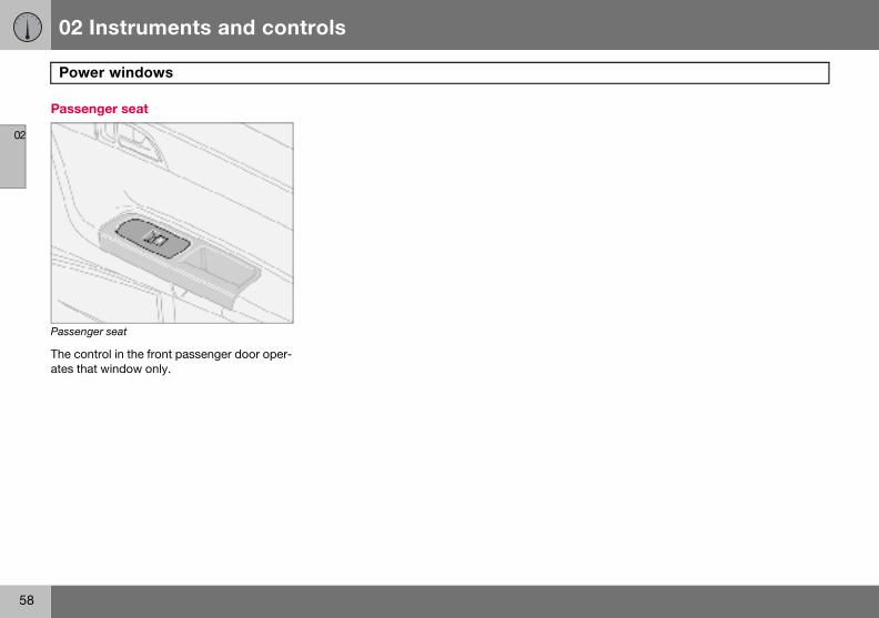
Passeng
The conates tha
r windows
ger seat
er seat
trol in the front passenger door oper-t window only.

02 Instruments and controls
59
Rearview and door mirrors
02
Interio
Bright lithe rearvdimminghind.
Dipping1. Con2. Norm3. Dim
AutomaBright lidimmed(1) is nodimming
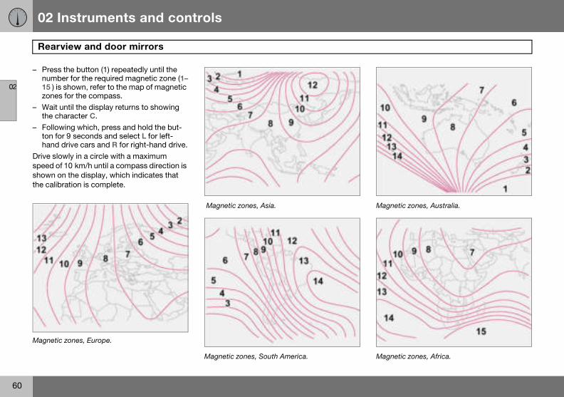
Calibrating the compass
The earth is divided into 15 magnetic zones. The compass is set for the geographical area to which the car was delivered. The compass should be calibrated if the car is moved across several magnetic zones.
– Stop the car in a wide open area with the engine running at idling speed.
– Press and hold button (1) for at least 6 seconds. Following which, the character C is shown (the button is con-cealed so use a paper clip for example to press it in).
– Press and hold button (1) for at least 3 seconds. The number for the current magnetic zone is displayed.
r rearview mirror
ght from behind could be reflected in iew mirror and dazzle the driver. Use when disturbed by light from be-
trol for dimmingal position
med position.
tic dimming (option) ght from behind is automatically by the rearview mirror. The control t available in mirrors with automatic .
Interior rearview mirror with compass (option on certain markets)
The upper right-hand corner of the rearview mirror has an integrated display that shows the compass direction in which the front of the car is pointing. Eight different directions are shown with English abbreviations: N (north), NE (north east), E (east), SE (south east), S (south), SW (south west), W (west) and NW (north west).
02 Instruments and controls
60
Rear
02
– Pressnumb15 ) iszones
– Wait the c
– Folloton fohand
Drive slospeed oshown othe calib
Magnetic
Magnetic zones, Australia.
Magnetic zones, Africa.
view and door mirrors
the button (1) repeatedly until the er for the required magnetic zone (1– shown, refer to the map of magnetic for the compass.
until the display returns to showing haracter C.wing which, press and hold the but-r 9 seconds and select L for left-
drive cars and R for right-hand drive.wly in a circle with a maximum
f 10 km/h until a compass direction is n the display, which indicates that ration is complete.
zones, Europe.
Magnetic zones, Asia.
Magnetic zones, South America.

02 Instruments and controls
61
Rearview and door mirrors
02
Door m
The conrors arerest. Theignition
– Pressmirrodoor nates
– Adjuscentr
– Pressgoes
Resetting to neutralMirrors that have been moved out of position by an external force must be reset to the neu-tral position for the electrical retracting and extending to work.
– Use the L and R buttons to retract the mirrors.
– Extend them again with the L and R but-tons. The mirrors are now reset in neutral position.
Approach and home safe lighting The lamp on the door mirrors (option) illumi-nates when the approach lighting or home safe lighting is activated.
Blind Spot Information System, BLIS (option)BLIS is an information system that under cer-tain conditions can help to draw the driver’s attention to vehicles moving in the same di-rection in the so-called "blind spot", see page 125.
irrors
trols for adjusting the two door mir- at the front of the driver’s door arm- rearview mirrors can be operated in
position I and II.
the L button for the left-hand door r or the R button for the right-hand mirror. The light on the button illumi-.t the position with the joystick in the e. the L or R button again. The lamp
out.
Retractable power door mirrors (option) The mirrors can be retracted for parking and driving in narrow spaces. This can be done in ignition position I and II.
Retracting the mirrors– Press down the L and R buttons at the
same time.– Release the buttons. The mirrors automat-
ically stop in the fully retracted position.
Folding out the mirrors– Press down the L and R buttons at the
same time.– Release the buttons. The mirrors automat-
ically stop in the fully extended position.
IMPORTANT
Do not use a scraper to remove ice from the mirrors as this can scratch the glass. Use the defroster function instead, see page 71.
WARNING
The driver-side door mirror is wide angled to provide optimal vision. Objects may ap-pear further away than they actually are.

02 Instruments and controls
62
Powe
02
Open p
The sunpanel. Tsitions:
A. Venti
B. Slidin
The igni
From ventilation position to fully open sun-roof:
– Pull the control rearward to the end position (1) and release.
Sliding position
Automatic operation– Pull the control past the point of
resistance (2) to the rear end position (1) or past the point of resistance (3) to the forward end position (4) and release. The sunroof opens/closes completely.
Manual operation
To open:– Pull the control rearward to the point of
resistance (2). The sunroof moves toward the fully open position as long as the button is held in this position.
To close:– Press the control forward to the point of
resistance (3). The sunroof moves toward the closed position as long as the button is held in this position.
W
If thereSwitchby remleaves
WARNING
The sunroof’s pinch-protection function only operates during automatic closing, not manual.
r sunroof (option)
ositions
roof controls are located in the roof he sunroof can be opened in two po-
lation position, up at the rear edge
g position, backwards/forwards
tion key must be in position I or II.
1. Opening, automatic2. Opening, manual3. Closing, manual4. Closing, automatic5. Opening, ventilation position6. Closing, ventilation position
Ventilation position
To open:– Press the rear edge of the control (5) up-
ward.To close:– Pull the rear edge of the control (6) down-
ward.
ARNING
are children in the car: off the supply to the power sunroof oving the ignition key if the driver the car.

02 Instruments and controls
63
Power sunroof (option)
02
Closingbutton
– PressseconThe d
If closin
– Press
W
Make sare notwhen ccontrocaution
with remote control or lock
and hold the lock button for two ds. The sunroof and windows close. oors lock.
g needs to be interrupted:
the lock button again.
Sunscreen The sunroof features a manual, sliding interi-or sunscreen. The sunscreen slides back au-tomatically when the sunroof is opened. Grip the handle and slide the screen forward to close it.
Pinch protection The sunroof’s pinch protection function is activated if the hatch is blocked by an object. If blocked, the sunroof will stop and automat-ically open to the previous position.
ARNING
ure that children or other passengers in danger of having hands trapped losing the sunroof with the remote
l. Always operate the sunroof with .
WARNING
The sunroof’s pinch-protection function only operates during automatic closing, not manual.Make sure children’s hands are clear when closing the sunroof.

02 Instruments and controls
64
Pers
02
Control p
limate control settings
uto blower adjust he fan speed can be set to AUTO mode in ars equipped with ECC:
Select from Low, Normal and High.
ecirculation timer hen the timer is active, the air recirculates r 3 – 12 minutes, depending on the outside
ir temperature.
Select On/Off depending on whether or not you wish the recirculation timer to be active.
eset allesets the climate function options to the ctory settings.
ar settings
nlock feedback light he hazard warning flashers can provide edback when the car is unlocked with the mote control. This function can be turned n/Off.
ock feedback light he hazard warning flashers can provide edback when the car is locked with the re-ote control. This function can be turned n/Off.
onal preferences
anel.
Possible settingsPersonal preferences can be set for some of the car’s functions. This applies to locks, cli-mate control and audio functions. For audio functions, see page 196.
Control panelA. Display
B. MENU
C. EXIT
D. ENTER
E. Navigation
UseThe settings are shown on the display (A).
Open the menu to enter settings:
– Press MENU (B).– Scroll, for example, to Car Settings with
the navigation button (E).– Press ENTER (D).– Select an alternative with the navigation
button (E).– Press ENTER to activate the selection.Close the menu:
– Press EXIT (C) for approximately one sec-ond.
C
ATc
–
RWfoa
–
RRfa
C
UTfereO
LTfemO

02 Instruments and controls
65
Personal preferences
02
AutomaWhen ththe doomaticallOff.
Unlock There ar
• All dotrol u
• Drivepressdrivelocks
Keyless• All do
unloc• One f
or theApproaSelect thon whenpressedable: 30
Home sSelect thon whenback aft
tic locking – doors e speed of the car exceeds 7 km/h
rs and tailgate can be locked auto-y. This function can be turned On/
doors e two alternatives for unlocking:
ors – one press of the remote con-nlocks both doors and the tailgate.r’s door first, then all others – one of the remote control unlocks the r’s door. A second press then un- the passenger door and the tailgate. entry ors – both doors and the tailgate are ked at the same time.ront door – either of the front doors tailgate can be unlocked separately.
ch lighting e time the car’s lights should remain the approach lighting button is . The following alternatives are avail-/60/90 seconds.
afe lighting e time the car’s lights should remain the left-hand stalk switch is pulled er the ignition key has been re-
moved. The following alternatives are availa-ble: 30/60/90 seconds.
Information• VIN number (Vehicle Identification
Number). The car’s unique identity number.
• Number of keys. The number of keys registered for the car is shown.

66
General information on climate control ....................................................68Manual climate control, A/C .....................................................................70Electronic climate control, ECC (option) ..................................................72Air distribution ..........................................................................................75Fuel-driven heater (option) ....................................................................... 76

03CLIMATE CONTROL
03 Climate control
68
Gene
03
Air conThe climwell as dcomparther matrol (ECC
MistingReduceon the inregular w
Ice andRemovetrol systbonnet
Fault trEntrust control sshop on
• Fan speed in AUTO mode (applies only to cars with ECC).
• Recirculation timer for passenger com-partment air.
For information about these settings, see page 64.
NO
The airbut to passenwindowbe on.
ral information on climate control
ditioning ate control system cools or heats as ehumidifies the air in the passenger
tment. The car is equipped with ei-nual (A/C ) or electronic climate con-
).
windows the problem of windows misting up side by cleaning the windows. Use a indow cleaner.
snow ice and snow from the climate con-em air intake (the grille between the and the windscreen).
acing and repairfault tracing and repair of the climate ystem to an authorised Volvo work-ly.
Refrigerant The air conditioning system contains R134a refrigerant. This refrigerant contains no chlo-rine, which means that it is harmless to the ozone layer. The system must only be charged with R134a refrigerant. Have an au-thorised Volvo workshop carry out this work.
Passenger compartment filter All air entering the car’s passenger compart-ment is only cleaned with one filter. This must be replaced at regular intervals. Follow the Volvo Service Programme for the recom-mended replacement intervals. If the car is used in a severely contaminated environ-ment, it may be necessary to replace the filter more often.
DisplayThere is a display above the climate control panel. This displays climate control settings.
Personal preferencesYou can set preferences for two climate con-trol functions:
TE
conditioning can be switched off, ensure the best possible air in the ger compartment and prevent the s from misting, it should always
NOTE
There are different types of passenger com-partment filter. Make sure that the correct filter is fitted.

03 Climate control
69
al information on climate control
03
Air ven
A. Open
B. Close
C. Later
D. Vertic
Aim thedows towindow
Cold wetimum c
CondensationIn warm weather, condensation from the air conditioning may drip under the car. This is normal.
Gener
ts in the dashboard
d
al airflow
al airflow
outer vents towards the side win- remove misting from the front side s.
ather: Close the centre vents for op-omfort and best demisting.
ECC (option)
Actual temperatureThe temperature you select corresponds to the physical experience with reference to factors such as air speed, humidity and solar radiation in and around the car.
Sensor location:• The sun sensor is on the top side of the
dashboard.• The temperature sensor for the passenger
compartment is behind the climate control panel.
Side windows and sunroofTo ensure that the air conditioning works sat-isfactorily, the side windows, and sunroof if appropriate, should be closed.
AccelerationThe air conditioning system switches off temporarily at full throttle. You may briefly feel a temporary rise in temperature.
NOTE
Do not cover or block the sensors with clothing or other objects.

03 Climate control
70
Manu
03
Contro
1. Fan2. Rec3. Defr4. Air d5. A/C 6. Hea7. Hea8. Rea
defr9. Tem
2. Recirculation Recirculation can be used to shut out bad air, exhaust fumes, etc. from the pas-senger compartment. The air in the passenger com-partment is recirculated. No outside air is taken into the
car. Recirculation (together with the air con-ditioning system) cools the passenger com-partment more quickly in hot weather. If the air in the car recirculates for too long then there is a risk of the windows misting.
al climate control, A/C
l panel
irculationosteristribution– On/Off (ON/OFF)ted front left seatted front right seatr window and door mirror ostersperature
Functions
1. Fan Increase or decrease the fan speed by turning the knob.
If the knob is turned anti-clockwise and the fan indi-cator in the display goes
out, the fan and the air conditioning are switched off. The display shows the fan sym-bol and OFF.

03 Climate control
71
Manual climate control, A/C
03
Timer The timemisting ed). Seevate thegram is
3. Defro
function
The follofroster fvide masenger c
• the aswitcA/C b
• recircWhen ththe climvious se
– Lower heat Press the button twice, one light illumi-nates.
– Heat off Press the button three times, light not illuminated.
8. Rear window and door mirror defrosters
Heating is used to quickly remove misting and ice from the rear window and door mirrors.
Press the switch once to start simultaneous rear win-
dow and rearview mirror defrosting. The function is active if one light is illuminated in the switch. The rearview mirror heating is de-activated automatically after approximately 6 minutes. The rear window heating is deac-tivated after approximately 12 minutes.
9. Temperature Select cooling or heating for both driver and passenger side.
r function reduces the risk of icing, and bad air (if recirculation is select- page 64, for how to activate/deacti- function. When the Defroster (3) pro-selected, recirculation is deactivated.
ster Used to quickly remove misting and ice from the windscreen and side win-dows. Air flows to the win-dows at high fan speed. The light in the defroster button illuminates when the
is active.
wing also takes place when the de-unction is activated in order to pro-ximum dehumidification in the pas-ompartment:
ir conditioning (A/C) is automatically hed on (can be switched off with the utton (5)ulation is automatically disengaged.e defroster function is switched off ate control system returns to the pre-ttings.
4. Air distributionThe airflow can be distribut-ed to the windows, dash-board vents or floor by pressing the air distribution buttons.
A symbol on the display above the climate control panel and an illumi-nated light in the button indicate which func-tion has been selected.
Refer to the table on page 75.
5. A/C – On/Off ON: Air conditioning is on. It is controlled by the system’s AUTO function. This way, in-coming air is cooled and de-humidified.
OFF: Air conditioning is off.
When the defroster function is activated the air conditioning is automatically switched on (can be switched off with the A/C button).
6. and 7. Heated front seats (option in certain markets)
– Higher heat Press the button once, both lights illuminate.

03 Climate control
72
Elect
03
Contro
1. AUT2. Fan3. Rec4. Defr5. Air d6. A/C 7. Hea8. Hea9. Rea
defr10.Tem
are switched off when AUTO is switched on. The display shows AUTO CLIMATE.
2. Fan Turn the knob to increase or decrease fan speed. If AUTO is selected then fan speed is regulated automat-ically. The previously set fan speed is disengaged.
ronic climate control, ECC (option)
l panel
O
irculation/Air quality systemosteristribution– On/Off (ON/OFF)ted front left seatted front right seatr window and door mirror ostersperature selector
Functions
1. AUTO The AUTO function auto-matically regulates climate control and maintains the selected temperature. The AUTO function controls heating, air conditioning, fan speed, recirculation, and air
distribution. If you select one or more manual functions, the other functions continue to be controlled automatically. All manual settings

03 Climate control
73
nic climate control, ECC (option)
033. Reci
car whein the carisk of m
Timer The timemisting ed). Seehow to a
• As a rule, the air quality sensor should always be engaged.
• Recirculation is limited in cold weather to avoid misting.
• If the insides of the windows start misting up, disengage the air quality sensor.
• The defroster function for the front, side and rear windows can also be used to demist the windows.
4. Defroster Used to quickly remove misting and ice from the windscreen and side win-dows. Air flows to the win-dows at high fan speed. The light in the defroster button illuminates when the
function is active.
The following also takes place when the de-froster function is activated in order to pro-vide maximum dehumidification in the pas-senger compartment:
• the air conditioning (A/C) is automatically switched on (can be switched off with the A/C button (6)
• recirculation is automatically disengaged.When the defroster function is switched off the climate control system returns to the pre-vious settings.
NO
If the kfan indand thThe dis
NO
When is alwa
Electro
rculation The function is selected to shut out bad air, exhaust gases etc. from the passen-ger compartment. The air in the passenger compart-ment is recirculated, i.e. no outside air is taken into the
n this function is activated. If the air r recirculates for too long, there is a isting on the insides of the windows.
r function reduces the risk of icing, and bad air (if recirculation is select- Personal preferences, page 64, for ctivate/deactivate the function.
3. Air quality system (option) (same button as recircula-tion)
The air quality system con-sists of a multi-filter and a sensor. The filter separates gases and particles to re-
duce the levels of odours and pollution in the passenger compartment. When the sensor detects polluted outside air, the air intakes are closed and the air in the passenger com-partment is recirculated. A green light (A) illu-minates in the button when the air quality sensor is active.
Activating the air quality sensor:
– Press AUTO (1) to activate the air quality sensor (normal setting).
Or:
– Switch between three functions by press-ing the recirculation button repeatedly.
• Air quality sensor engaged – the light (A) illuminates.
• No recirculation engaged, provided it is not required for cooling in hot weather – light not illuminated.
• Recirculation engaged – the light (M) illu-minates.
Keep the following in mind:
TE
nob is turned anticlockwise and the icator in the display goes out, the fan e air conditioning are switched off. play shows the fan symbol and OFF.
TE
Defroster (4) is selected, recirculation ys deactivated.

03 Climate control
74
Elect
03
5. Air d
above thnated ligtion has
Refer to
6. A/C –
When thair cond(can be
10. Temperature selector The temperatures on the driver and passenger sides can be set independently.
Press the button once to activate one side only. Press again to activate the
other side. Press the button a third time to activate both sides.
The active side is indicated by the button’s light and on the display above the climate control panel.
When the car is started, the most recent set-ting is resumed.
NOTE
Heating or cooling cannot be hastened by selecting a higher or lower temperature than the actual desired temperature.
ronic climate control, ECC (option)
istribution The airflow can be distribut-ed to the windows, dash-board vents or floor by pressing the air distribution buttons.
A symbol on the display e climate control panel and an illumi-ht in the button indicate which func-
been selected.
the table on page 75.
On/Off (ON/OFF) ON: Air conditioning is on. It is controlled by the sys-tem’s AUTO function. This way, incoming air is cooled and dehumidified.
OFF: Air conditioning is off.
e defroster function is activated the itioning is automatically switched on switched off with the A/C button).
7. and 8. Heated front seats (option in certain markets)
To activate front seat heat-ing:
– Higher heat: Press the button once – both lights illumi-nate.
– Lower heat: Press the button twice – one light illumi-nates.
– Heat off: Press the button three times – light not illuminated.
9. Rear window and door mirror defrosters
Heating is used to quickly remove misting and ice from the rear window and door mirrors.
Press the switch once to start simultaneous rear win-
dow and rearview mirror defrosting. The function is active if one light is illuminated in the switch. The rearview mirror heating is de-activated automatically after approximately 6 minutes. The rear window heating is deac-tivated after approximately 12 minutes.
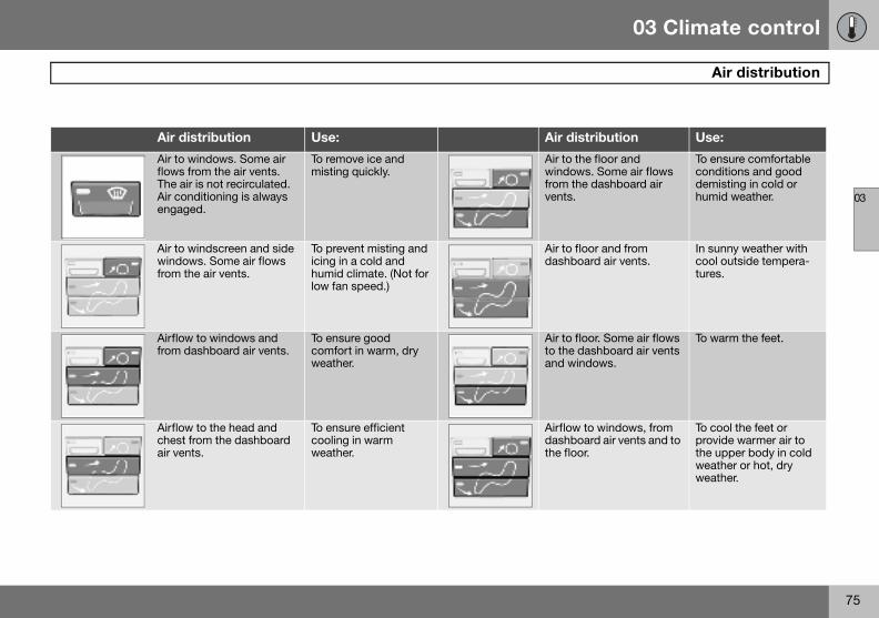
03 Climate control
75
Air distribution
03
tribution Use:
he floor and s. Some air flows
e dashboard air
To ensure comfortable conditions and good demisting in cold or humid weather.
loor and from ard air vents.
In sunny weather with cool outside tempera-tures.
loor. Some air flows ashboard air vents
ndows.
To warm the feet.
to windows, from ard air vents and to r.
To cool the feet or provide warmer air to the upper body in cold weather or hot, dry weather.
Air distribution Use: Air dis
Air to windows. Some air flows from the air vents. The air is not recirculated. Air conditioning is always engaged.
To remove ice and misting quickly.
Air to twindowfrom thvents.
Air to windscreen and side windows. Some air flows from the air vents.
To prevent misting and icing in a cold and humid climate. (Not for low fan speed.)
Air to fdashbo
Airflow to windows and from dashboard air vents.
To ensure good comfort in warm, dry weather.
Air to fto the dand wi
Airflow to the head and chest from the dashboard air vents.
To ensure efficient cooling in warm weather.
Airflowdashbothe floo

03 Climate control
76
Fuel-
03
Genera
The parately or ing TIMErefers toThe car’heating side temoutdoorperaturerunning 60 minu
ParkingIf the cathe car sthere is heater.
Activating the heater
– Enter the time when the car is to be used. Press RESET (C) to enter the hours and minutes.
– Press and hold the RESET (C) button until the timer is activated.
Direct start– Use the thumbwheel (B) to scroll to
DIRECT START.– Press RESET (C) to access the options
ON and OFF.– Select ON. The heater will now run for
60 minutes. Heating of the passenger compartment will begin as soon as the engine coolant has reached a temperature of 30 ºC.
W
The caor dies
driven heater (option)
l information about heaters
king heater can be started immedi-set with two different start times us-R 1 and TIMER 2. Here, start time
the time the car is heated and ready. s electronic system calculates when should be started based on the out-perature. The heater is not run if the
temperature exceeds 25 �C. At tem-s of –10 �C and below, the maximum time of the parking heater is tes.
on a hill r is parked on a steep hill, the front of hould point downhill to ensure that
a supply of fuel to the parking
Warning decal on fuel filler flap.
ARNING
r must be outdoors when the petrol el heater is used.
WARNING
Switch off the fuel-driven heater before starting to refuel. Fuel which spills onto the ground can be ignited.Check the information display to see that the heater is switched off. When the parking heater is running, PARK HEAT ON is shown on the information display.

03 Climate control
77
Fuel-driven heater (option)
03
Immed– Use t
DIRE– Press
ON a– Selec
BatteryIf the bafuel leveswitchepears onedge the
Clock/timerIf the car clock is reset after the heater timers are programmed, the selected times will be cancelled.
Additional heater (diesel) (certain countries)
Extra heat from the additional heater may be required in cold weather to reach the correct temperature in the passenger compartment.
The additional heater starts automatically when extra heat is required if the engine is running. It is switched off automatically when the correct temperature is reached or when the engine is switched off.
NO
The caparking
IM
Repeabined wthe batis usedthe samthat thbattery
iate stop of heaterhe thumbwheel (B) to scroll to CT START. RESET (C) to access the options nd OFF.t OFF.
and fuel ttery has insufficient charge or the l is too low, the parking heater will be d off automatically. A message ap- the information display. Acknowl- message by pressing READ (A).
Setting the TIMER 1 and 2 For safety reasons, you can only programme times for the following 24 hours, not several days in advance.
– Scroll with the thumbwheel to TIMER. – Touch RESET to move to the flashing
hours setting.– Scroll with the thumbwheel to the desired
hour.– Touch RESET to move to the flashing
minutes setting.– Scroll with the thumbwheel to the desired
minute.– Touch RESET to confirm the setting.– Press RESET to activate the timer. After
setting TIMER 1 a second start time can be programmed with TIMER 2. Access this with the thumbwheel. Set the alterna-tive start time in the same way as TIMER 1.
Messages on the displayWhen TIMER 1, TIMER 2 and DIRECT START are activated, the information symbol on the combined instrument panel illumi-nates and an explanatory text appears on the information display. The display also indi-cates which TIMER is active when the driver removes the key from the ignition to leave the car.
TE
r can be started and driven while the heater is still running.
PORTANT
ted use of the parking heater com-ith short journeys may discharge
tery and impair starting. If the heater regularly, the car must be driven for e time as the heater is run to ensure
e alternator has time to charge the .

78
Front seats ...............................................................................................80Interior lighting .........................................................................................82Storage spaces in the passenger compartment ......................................84Rear seat ..................................................................................................86Cargo area ................................................................................................87

04INTERIOR

04 Interior
80
Fron
04
Seating
The drivjusted tositions.
1. Forwjust and after
2. Raispum
3. Rais4. Lum5. Adju6. Con
Power seatMove the seat forward:
– Move the handle (1) up to release the backrest.
– Fold the backrest forward until it locks.– Press the button (2) located beside the
head restraint. Keep it depressed.
Easy entry
Move the seat backward:
– Press the button (2) located to the side of the head restraint. Keep it depressed.
– Move the handle (1) up and fold back the backrest.
1 Also ap
t seats
position
er’s and passenger seats can be ad- the optimum sitting and driving po-
ard/backward: lift the handle to ad-the distance to the steering wheel pedals. Check that the seat is locked changing position.e/lower front edge of seat cushion, p up/down.e/lower the seat, pump up/down.bar support1, turn the wheel.st backrest rake, turn the wheel.trol panel for power seat (option).
The lever (2) is not available for all seat mod-els.
Entry to the rear seat – Easy entry Make sure that the seatbelt is removed from the belt guide before passengers enter or exit the car, see page 14. The easy entry position is intended for use when the seat is empty.
Mechanical seatMove the seat forward:
– Move the handle (1) up to release the backrest.
– Fold the backrest forward until it locks.– Release the handle and slide the seat
forwards.Move the seat backward:
– Move the seat backward to the original position.
– Move the handle (1) up to fold the back-rest back.
The seat returns to the same position it had before folding forward for easy entry.
plies to power seat.
WARNING
Adjust the position of the driver’s seat be-fore setting off, never while driving.Check that the seat is locked in position.

04 Interior
81
Front seats
04
The beltin the bethere is
Floor mVolvo suly produ
Memory function
Buttons for memory function
Store setting– Adjust seat.– Press and hold button M while pressing
button 1, 2 or 3 simultaneously.
Using a stored settingPress one of the memory buttons 1 – 3 until the seat stops. If you release the button then the movement of the seat will stop.
NO
The sefront (+and frohas beIf the bis in thmaticafew se
W
Checkback bstraint.
W
The flofirmly fclips toaround
on the front passenger side must be lt guide during driving, even when
no passenger sitting in the seat.
ats (option) pplies floor mats which are especial-ced for your car.
Power seat (option)
The seats can be adjusted for a certain time after unlocking the door with the remote con-trol without the key being inserted into the ig-nition switch. The seat can always be adjust-ed in ignition position I or II.
1. Front edge of seat cushion up/down2. Seat, forwards/backwards 3. Seat, up/down4. Backrest rakeAn overload protection is deployed if one of the seats is blocked. If this happens, turn off the ignition and wait a short time before ad-justing the seat again. Only one of the seat’s settings can be adjusted at a time.
TE
at can only be moved to the very 6 cm) to facilitate entry and exit to m the rear seat when the backrest en folded forward. ackrest is folded back when the seat e front position then the seat auto-lly moves back approx. 6 cm after a conds.
ARNING
that the backrest is properly folded y pushing and pulling the head re-
ARNING
or mat at the driver’s seat must be itted and secured in the attachment prevent it from being trapped and under the pedals.

04 Interior
82
Inter
04
EmergeIf the seany of th
Key meThe drivkey memwith theunlockedriver’s the drive
• On – left-hand side depressed, passenger compartment lighting on.
The reading lamps can be switched on in ig-nition position I and II as well as when the en-gine is running. They can also be activated within 30 minutes after the engine has been switched off or when one of the doors has been opened/closed.
Cargo area lighting
Interior lighting in rear seat and cargo area.
Cargo area lighting includes a further lamp on the left-hand side of the cargo area.
W
Risk ofnot plaCheckbehindEnsuregers ca
NO
The kememo
ior lighting
ncy stopat accidentally begins to move, press e buttons to stop the function.
mory in remote control key er’s seat settings are stored in the ory when the car has been locked
remote control key. When the car is d with the same remote control the seat adopts the stored settings when r’s door is opened.
Reading lamps and interior lighting
Passenger compartment lighting and reading lamps.
1. Reading lamp left-hand, On/Off2. Passenger compartment lighting front
and rear3. Reading lamp right-hand, On/OffSwitch (2) has three positions for the interior lighting:
• Off (0) – right-hand side depressed, auto-matic lighting off.
• Neutral position – interior lighting comes on when a door is opened and goes out when the door is closed. The dimmer function is active.
ARNING
crushing. Make sure that children do y with the controls. that there are no objects in front of, or under the seat during adjustment. that none of the rear seat passen-n be trapped.
TE
y memory is independent of the seat ry.

04 Interior
83
Interior lighting
04
The intewhen thfor 5 min
The ligh
• if the• if the
Vanity mirror1
The light illuminates automatically when the cover is lifted.
1 Option in certain markets.
rior and cargo area lighting illuminate e tailgate is opened and remain on utes.
ting is switched off:
tailgate is closed button (2) is set in Off position (0).
Automatic lighting The passenger compartment lighting is switched on and off automatically when button (2) is in neutral position.
The passenger compartment lighting is switched on and remains on for 30 seconds if:
• the car is unlocked from the outside with the key or remote control
• the engine is stopped and the ignition key is turned to position 0
The passenger compartment lighting is switched off when:
• the engine is started• the car is locked from the outside with the
key or remote controlThe passenger compartment lighting comes on and remains on for 5 minutes if one of the doors is open.
The interior and cargo area lighting can be switched on or off within 30 minutes, from when the key is turned to position 0, with switch (2). The lighting remains on for 5 minutes if it is not switched off.

04 Interior
84
Stora
04
ge spaces in the passenger compartment

04 Interior
85
s in the passenger compartment
04
Storag
1. Stor2. Stor
seat3. Tick4. Coa5. Glov6. Stor7. Stor
disc8. Bott9. Stor
panecans
10.Stor11.Stor
zine
Floor mats (option) Volvo supplies floor mats which are especial-ly produced for your car.
1 Storage
W
Ensurelie or pcause Alwaysa seatb
WARNING
The floor mat at the driver’s seat must be firmly fitted and secured in the attachment clips to prevent it from being trapped around and under the pedals.
Storage space
e spaces
age compartments in doorsage pocket on front edge of front cushions (trim dependent)et clipt hanger, only for light garmentseboxage compartmentage compartment (e.g. for CD s) and cup holder1
le holder (option)age compartments in rear side ls with space for up to three soda
age compartment for first aidage pockets for maps and maga-s
Glovebox
1. Unlocking2. LockingThe owner’s manual and maps can be kept here. There are also holders for coins, pens and fuel cards. The glovebox can be locked manually with the detachable key blade in the remote control. More information on the key blade is on page 95.
compartment in certain markets.
ARNING
that no hard, sharp or heavy objects rotrude in such a way that they could injury during heavy braking. secure large and heavy objects with elt or cargo retaining straps.

04 Interior
86
Rear
04
Loweri
The rearwards toeasier to
Loweri– Pull t
releashowlocke
– Fold Raising– Fold – Place– Press
posit– Chec
rmrest in the rear seat
he armrest in the rear seat can be folded own for passenger comfort or to make pace for a long load. The armrest folds own when one of the backrests is folded own.
or securing loads, see page 140.
seat
ng the rear seat backrest
seat backrests can be tipped for-gether, or individually, to make it transport long objects.
ng the backrest:he lock catch up and forward to se the backrest. A red indicator (A) s that the backrest is no longer d in place.the backrest forward. the backrest:
up the backrest. the seatbelt over the backrest. the backrest backwards into locked
ion.k that the backrest is locked.
A
Tdsdd
F
WARNING
Place the belt straps over the backrests be-fore folding them back to their secured po-sitions.
NOTE
When the backrest has been raised, the red indicator (A) should no longer be showing. If it is still showing then the backrest is not locked in place.

04 Interior
87
Cargo area
04
Bottle
There iscated to
– Hook in the hooks in the rear load retain-ing eyelets (D).
Hanging up the cargo cover when not in use– Unhook the hooks from the rear load
retaining eyelets (D).– Press the rail together and remove it from
the rear bracket (C). Place the rail at the front of the cargo area floor.
– Hook in the hooks in the rail next to the mounting points (B).
The cargo cover now hangs next to the rear seat backrest ready for the next time it is to be used.
Removing the cargo cover– Unhook the hooks and remove one rail at
a time by pressing them together and removing them from their mounting points.
– When all mounting points are detached the cargo cover can be rolled up and placed at the rear of the cargo area floor to make space for bulky loads.
NOTE
The cargo cover has no load-securing func-tion Never load anything on top of the cargo cover. For securing loads, see page 140.
holder (option)
a bottle holder for larger bottles lo- the rear of the tunnel console.
Soft cargo cover (option)
Soft cargo cover
The cargo cover is pulled over the luggage and secured in the rear load retaining eyelets. Undo (D) and, if necessary, (C) during load-ing.
Fitting the cargo cover– Hook in the hooks in the front load retain-
ing eyelets by the floor (A).– Fit the front brackets in (B) by pressing
together the spring-loaded rail and fit it into place on both sides.
– Fit the rear brackets in (C) in the same way.

04 Interior
88
Carg
04
Hard c
Fitting – Retra
lock bliftingarea.posit
– Lift thcargoand a
Removing the cargo cover– Retract the front lock plungers at (A) to
their end positions by pulling back the lock buttons on both sides.
– Retract the rear lock plungers at (B) to their end positions by pulling back the lock buttons on both sides.
– Lift up and turn the cargo cover before lifting it from the cargo area.
NOTE
The cargo cover has no load-securing func-tion Never load anything on top of the cargo cover. For securing loads, see page 140.
o area
argo cover (option)
the cargo coverct all four lock plungers by pulling the uttons to their end positions before
in the cargo cover into the cargo The lock plungers stop in retracted ion.e cargo cover carefully into the area sideways, turn it back around ngle the front edge up slightly.
Locks and support pins
– Locate the front section of the two support pins behind the active locks (A) on both sides.
– Align one of the rear locks at (B) and extend the lock plunger by moving the lock button forwards.
– Align the other rear lock in the same way and extend the lock plunger by moving the lock button forwards.
– Extend the front lock plungers, one at a time so that they lock in their active locks (A).
The cargo cover hatch can be raised during loading.

04 Interior
89
Cargo area
04
Raising
WithouRaise thon both
With haRaise thraise thelocated
the floor hatch
t cargo covere floor hatch and secure it in the lugs sides.
rd cargo covere hatch on the cargo cover. Then floor hatch and hook it into the hook under the cargo cover.
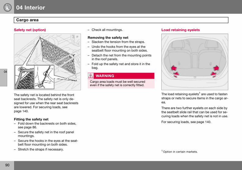
04 Interior
90
Carg
04
Safety
The safeseat bacsigned fare lowepage 14
Fitting – Fold
see p– Secu
moun– Secu
belt f– Stretc
Load retaining eyelets
The load retaining eyelets1 are used to fasten straps or nets to secure items in the cargo ar-ea.
There are two further eyelets on each side by the seatbelt slide rail that can be used for se-curing loads when the safety net is not in use.
For securing loads, see page 140.
1 Option in certain markets.
o area
net (option)
ty net is located behind the front krests. The safety net is only de-
or use when the rear seat backrests red. For securing loads, see 0.
the safety netdown the backrests on both sides, age 86.re the safety net in the roof panel tings.re the hooks in the eyes at the seat-loor mounting on both sides.h the straps if necessary.
– Check all mountings.
Removing the safety net– Slacken the tension from the straps.– Undo the hooks from the eyes at the
seatbelt floor mounting on both sides.– Detach the net from the mounting points
in the roof panels.– Fold up the safety net and store it in the
bag.
WARNING
Cargo area loads must be well secured even if the safety net is correctly fitted.

04 Interior
91
04

92
Remote control with key blade ................................................................94Keyless drive (option) ...............................................................................98Locking and unlocking ...........................................................................100Alarm (option) ......................................................................................... 103

05LOCKS AND ALARM
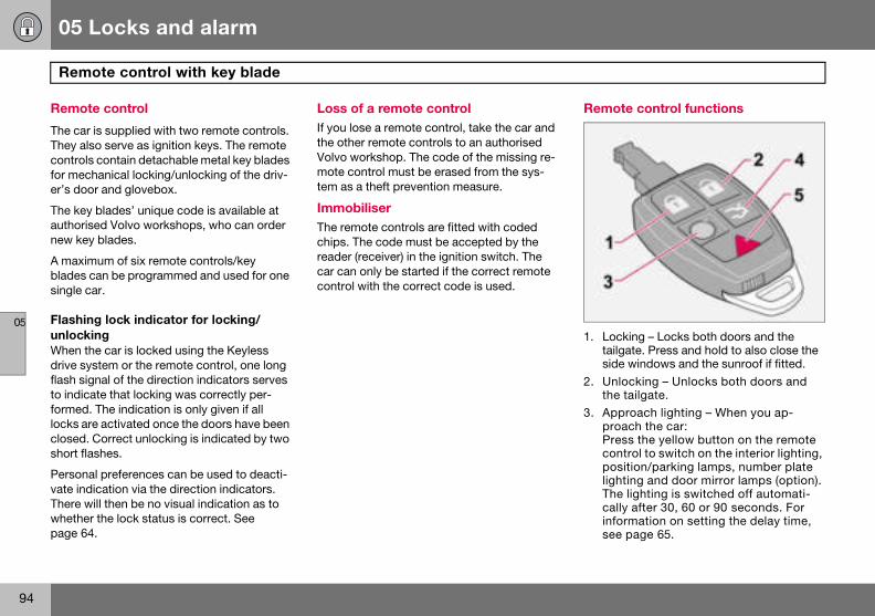
05 Locks and alarm
94
Rem
05
Remot
The car They alscontrolsfor mecer’s doo
The keyauthorisnew key
A maximblades csingle c
FlashinunlockiWhen thdrive syflash sigto indicaformed.locks arclosed. short fla
Personavate indThere wwhetherpage 64
Remote control functions
1. Locking – Locks both doors and the tailgate. Press and hold to also close the side windows and the sunroof if fitted.
2. Unlocking – Unlocks both doors and the tailgate.
3. Approach lighting – When you ap-proach the car: Press the yellow button on the remote control to switch on the interior lighting, position/parking lamps, number plate lighting and door mirror lamps (option). The lighting is switched off automati-cally after 30, 60 or 90 seconds. For information on setting the delay time, see page 65.
ote control with key blade
e control
is supplied with two remote controls. o serve as ignition keys. The remote contain detachable metal key blades hanical locking/unlocking of the driv-r and glovebox.
blades’ unique code is available at ed Volvo workshops, who can order blades.
um of six remote controls/key an be programmed and used for one
ar.
g lock indicator for locking/nge car is locked using the Keyless stem or the remote control, one long nal of the direction indicators serves te that locking was correctly per-
The indication is only given if all e activated once the doors have been Correct unlocking is indicated by two shes.
l preferences can be used to deacti-ication via the direction indicators. ill then be no visual indication as to the lock status is correct. See .
Loss of a remote controlIf you lose a remote control, take the car and the other remote controls to an authorised Volvo workshop. The code of the missing re-mote control must be erased from the sys-tem as a theft prevention measure.
Immobiliser The remote controls are fitted with coded chips. The code must be accepted by the reader (receiver) in the ignition switch. The car can only be started if the correct remote control with the correct code is used.

05 Locks and alarm
95
Remote control with key blade
05
4. Tailgunlo
5. Pantion the rondssecocatobe tuonce5 seswit30 s
Key blaThis feacar, suchotel etckeep the
NO
The fun
IM
The naparticuchip. Tdamag
ate – Press the button once to ck the tailgate only.
ic function – Used to attract atten-in an emergency. Press and hold ed button for at least three sec- or press it twice within three nds to activate the direction indi-rs and the horn. The function can rned off with the same button it has been active for at least
conds. Otherwise the function ches off automatically after econds.
de ture is intended for when leaving the h as for servicing or valet parking at a . Hand over the remote control and detachable key blade.
Removing the key bladeTake the key blade from the remote control:
– Slide the spring-loaded catch (1) to the side while pulling the key blade (2) out backwards.
Inserting the key bladeBe careful when inserting the key blade back into the remote control.
– Hold the remote control with the narrow end pointing down and lower the key blade into its slot.
– Lightly press the key blade to lock it in position. You should hear a "click".
TE
ction does not open the tailgate.
PORTANT
rrow section of the remote control is larly sensitive - this contains the he car cannot be started if the chip is ed.

05 Locks and alarm
96
Rem
05
Key bla
Active 1. Activ2. ActiThe detatrol is usdriver’s locking
NO
Using mote ctriggerthe rem
ote control with key blade
de
lockse locks, remote control
ve locks, key bladechable key blade of the remote con-ed to lock or unlock the glovebox or door (without activating the central system).
TE
the detachable key blade of the re-ontrol to unlock the driver’s door will the alarm. Switch off the alarm with ote control. See page 104.

05 Locks and alarm
97
Remote control with key blade
05
Weak r
When thtionalitytion symVOLTAG
– Refit the cover and screw it shut.– Press the key blade back into place.Dispose of the old battery in an environmen-tally-friendly way.
emote control battery
e battery runs down and full func- cannot be guaranteed, the informa-bol and REMOTE BATTERY LOW E appear on the display.
Replacing the remote control battery
If the locks repeatedly fail to respond to sig-nals from the remote control at a normal dis-tance, the battery should be replaced (type CR 2032, 3 V).
– Pull out the key blade.– Place the remote control with the keypad
downward and remove the screw (1) using a small screwdriver.
– Remove the cover.– Carefully note the position of the battery’s
+ and – poles on the inside of the cover.– Prise out (2) and change the battery. Avoid
touching the battery and its terminals with your fingers.

05 Locks and alarm
98
Keyle
05
Keyles
The keyunlockeneed forremote
The sysvenient shoppinother. Itfor the r
The twoless drivremote can han
• the READ button has been pressed.
Never leave any remote control in the carIf a remote control with keyless drive function is left in the car, it is made passive when the car is locked. This prevents unauthorised en-try.
If someone breaks into the car and finds the remote control, it can be activated and used again. It is therefore important to handle all remote controls with equal care.
Interference to remote control functionElectromagnetic screening and fields can in-terfere with the keyless drive system. To avoid this: do not place the remote control near mobile phones, metallic objects or, for example, in a metal briefcase.
If interference is experienced nonetheless, use the remote control and key blade in the normal way, see page 94.
ss drive (option)
s lock and ignition system
less drive system allows the car to be d, driven and locked without the a key. You simply need to have the
control with you in a pocket or a bag.
tem makes it easier and more con-to open the car, for example with g bags in one hand and a child in the saves you having to take out or look emote control.
remote controls incorporate the key-e feature. You can order additional controls. The keyless drive system dle up to six remote controls.
Remote control max. 1.5 m from the carIn order to open a door or the tailgate, a re-mote control must be no more than approx. 1.5 metres from the car door handle or tail-gate.
This means that the person who wishes to open a door must have the remote control with him or her. It is not possible to open a door if the remote control is on the other side of the car.
The grey areas in the illustration indicate the range covered by the system’s antennas.
If someone leaves the car and takes a key-less drive remote control with them, a warn-ing message appears on the information dis-play and a reminder signal sounds. The warning message disappears when the re-mote control is brought back to the car or when the ignition dial is turned to position 0. The warning is only issued if the ignition dial is in position I or II after someone has opened and closed a door.
The warning message and reminder signal disappear when the remote control is brought back to the car after one of the fol-lowing actions:
• a door has been opened and closed• the ignition dial has been turned to
position 0

05 Locks and alarm
99
Keyless drive (option)
05
UnlockWhen thcovered
– Openhand
– Opentailgagate.
If for somin the recan be ufunction
LockingLock the doors and tailgate as follows:
– Push in the lock button on one of the door handles.
Both doors and the tailgate must be closed before the lock button can be pressed. Oth-erwise they will not lock.
When the car is locked, the lock buttons on the inside of the doors retract.
Personal preferencesThe Keyless Drive system can have personal preferences applied, see page 65.
ing e remote control is within the range by the system’s antennas:
the doors by pulling the relevant le. the tailgate by pressing under the te opening button and lift the tail-
e reason the keyless drive function mote control is not operating, the car nlocked using the remote control s, see page 94.
Unlocking using the key blade
The driver’s door can be opened as follows (central locking system not activated):
– Carefully prise out the plastic cover in the handle by inserting the key blade in the hole on the bottom of the cover.
– Unlock the door using the key blade.
Power seat (option) – remote control with memory functionIf several people with keyless drive remote controls get into the car, then the driver’s seat will be adjusted for the person who opens the door first.
05 Locks and alarm
100
Lock
05
Lockinoutside
UnlockThe remthe car ipersona
• with otailga
• with oand wdoor
LockingThe remtailgate and insi
The fuelis locked
Tailgate
UnlockingUnlocking tailgate only:
– Press the remote control button to unlock the tailgate.
LockingIf the doors are locked when the tailgate is closed then it remains unlocked. Lock with the remote control or from inside to lock both doors and the tailgate.
NO
The catailgatethere is
1Applie
ing and unlocking
g/unlocking the car from
ingote control unlock button can unlock n two different ways (select option in l preferences, see page 65):
ne press unlock both doors and the tene press unlock the driver’s door ith a second press unlock the other
and the tailgate.
ote control locks both doors and the simultaneously. Door lock buttons de door handles are disengaged.
filler flap cannot be opened if the car with the remote control.
Automatic relocking If none of the doors or the tailgate is opened within two minutes of unlocking, all are locked again automatically (does not apply to locking from inside). This function reduces the risk of the car being left unlocked unin-tentionally. For cars with alarms, see page 104.
Automatic locking When the speed of the car exceeds 7 km/h the doors and tailgate can be locked auto-matically.
When the function is activated and the doors have been locked they can be opened in two ways:
• pull one of the door handles twice• press the unlock button by the door han-
dle.The function can be activated/deactivated by means of personal preferences, see page 65.
TE
r can be locked1 even if a door or the is open. When the door is closed a risk that the keys will be locked in.
s to certain markets
WARNING
Be aware that you can be locked in the car if it is locked from the outside with the remote control. You cannot then leave the car using any of the controls inside the car.

05 Locks and alarm
101
Locking and unlocking
05
Lockin
The doounlocketon by th
Unlock– Press
Pressdows
Locking– Press
Presswindo
Both dolock but
Locking the glovebox
The glovebox can only be locked and un-locked with the detachable key blade in the remote control.
• Unlock the glovebox (1) by turning the key a quarter of a turn (90 degrees) anticlock-wise. The keyhole is vertical in the un-locked position.
• Lock (2) the glovebox by turning the key a quarter of a turn (90 degrees) clockwise. The keyhole is horizontal in the locked position.
g/unlocking from inside
rs and the tailgate can be locked or d simultaneously using the lock but-e door handle.
ing the upper section of the lock button. and hold to also open all side win-.
the lower section of the lock button. and hold to also close all of the ws and the sunroof if fitted.
ors and tailgate are locked with the ton in the driver’s or passenger door.
Opening the doorsWhen the doors are locked from the inside:
– Pull the handle twice to unlock and open the doors.

05 Locks and alarm
102
Lock
05
Deadlo
When dopenedThis is adeadlocter the d
The car lock modoors cawith the
If the car is equipped with an alarm, the movement and tilt detectors are also deacti-vated at the same time, see page 104.
The light in the button illuminates until the car is locked with the key or the remote control. A message remains on the display as long as the key remains in the ignition switch. The detectors are reactivated and deadlocks re-engaged the next time the ignition is switched on.
WARNING
Do not allow anyone to remain in the car without first deactivating the deadlocks.
ing and unlocking
cks
eadlocked, the doors cannot be from the inside if they are locked. ctivated with the remote control. The ks are set after a 25 second delay af-oors are locked.
can only be unlocked from the dead-de with the remote control. The n also be opened from the outside
key.
1. Deactivation of the detectors and dead-locks
2. No function
Temporary deactivation of the deadlocks and any alarm detectors If someone is going to stay in the car but you still want to lock the doors from the outside, the deadlocks can be disabled.
– Insert the key into the ignition switch, turn it to position II and then back to position I or 0.
– Press the button (1).

05 Locks and alarm
103
Alarm (option)
05
Alarm
When thtors all a
The alar
• a doo• a non
or if a• a mo
compdetec
• the cwith a
• a bat• anyo
If there is a fault in the alarm system, a mes-sage appears on the information display. Contact an authorised Volvo workshop.
Arming the alarm – Press the lock button on the remote con-
trol. A long flash from the car’s direction indicators confirms that the alarm is armed and that all the doors are locked.
Disarming the alarm – Press the unlock button on the remote
control. Two short flashes from the car’s direction indicators confirms that the alarm is disarmed and that both doors are unlocked.
NOTE
Do not attempt to repair or modify alarm system components. All such attempts could affect the terms of insurance.
IMPORTANT
The alarm is fully armed when the car’s di-rection indicators have made one long flash and the light on the dashboard flashes once per second.
system
e alarm is armed, it continually moni-larm inputs.
m is triggered if:
r, the bonnet or tailgate opens-approved key is used in the ignition n attempt is made to force the lockvement is detected in the passenger artment (if fitted with a movement tor)
ar is raised or towed away (if fitted tilt detector)
tery cable is disconnectedne tries to disconnect the siren.
Alarm lamp on instrument panel
A light on the instrument panel indicates the alarm system’s status:
• Lamp not lit – the alarm is not armed.• The lamp flashes rapidly after disarming
the alarm and until the ignition is switched on – the alarm has been triggered.
• The lamp flashes once every other second after the car’s direction indicators have given one long flash – the alarm is armed.

05 Locks and alarm
104
Alarm
05
AutomThis funing the c
If none oopenedalarm (athe remly rearmtime.
Deacti– Press
contrswitc
Confirmfrom the
Alarm When thhappen
• A sireThe susedcharg
• The dutes o
RemotIf for somworkingand the
– Turn the ignition key to position II and then back to position 0. Remove the key.
– Press button (1). The lamp in the button is illuminated until the car is locked.
A message remains on the display as long as the key remains in the ignition switch (or for one minute after the key is removed).
The detectors are reactivated the next time the ignition is switched on.
If the car has deadlocks, these are also re-engaged.
(option)
atic alarm activation ction prevents you accidentally leav-ar without the alarm on.
f the doors or the tailgate are within two minutes of disarming the nd the car has been unlocked with ote control), the alarm is automatical-ed. The car is locked at the same
vating a triggered alarm the unlock button on the remote ol or insert the key in the ignition h.ation is given by two short flashes direction indicators.
signals e alarm is triggered, the following
s:
n sounds for less than 25 seconds. iren has its own battery which is if the car battery has insufficient e or is disconnected.irection indicators flash for five min-r until the alarm is deactivated.
e control not workinge reason the remote control is not
, the alarm can still be switched off car started as follows:
– Open the driver’s door with the key blade. The alarm is triggered and the siren sounds.
– Insert the remote control into the ignition switch. The alarm is deactivated. The alarm lamp flashes rapidly until the ignition key is turned to position II.
Temporary deactivation of the deadlocks and alarm detectors
1. Deactivation of the detectors2. No functionTo prevent the alarm being triggered errone-ously, such as during a ferry journey, the movement and tilt detectors can be tempo-rarily disengaged.

05 Locks and alarm
105
Alarm (option)
05
Testing
Testingpassen– Open– Arm t
confi– Wait – Test
sengout asounflash.
– Deacwith t
Testing– Arm t– Wait – Unloc
blade– Open
sounflash.
– Deacwith t
Testing– Sit in
ment
the alarm system
the movement detector in the ger compartment all windows.he alarm. Activation of the alarm is rmed by the lamp flashing slowly.30 seconds.the movement detector in the pas-er compartment, such as by lifting bag from a seat. A siren should d and all direction indicators should
tivate the alarm by unlocking the car he remote control.
the doorshe alarm. 30 seconds.k the driver’s door with the key . one of the doors. A siren should d and all direction indicators should
tivate the alarm by unlocking the car he remote control.
the bonnet the car and deactivate the move- detector.
– Arm the alarm. Remain in the car and lock the doors with the button on the remote control.
– Wait 30 seconds.– Open the bonnet with the handle under
the dashboard. A siren should sound and all direction indicators should flash.
– Deactivate the alarm by unlocking the car with the remote control.

106
General ................................................................................................... 108Refuelling ............................................................................................... 110Starting the engine ..................................................................................111Keyless drive (option) ............................................................................. 113Manual gearbox ..................................................................................... 114Automatic gearbox ................................................................................ 116Brake system ......................................................................................... 119Stability and traction control system .................................................................................................... 121Parking assistance (option) .................................................................... 123Blind Spot Information System BLIS (option) ................................................................................................... 125Towing and recovery .............................................................................. 128Jump starting ......................................................................................... 130Driving with a trailer ............................................................................... 131Towing bracket ....................................................................................... 133Detachable towbar ................................................................................. 135Loading .................................................................................................. 140Adjusting headlamp pattern ................................................................... 141

06STARTING AND DRIVING

06 Starting and driving
108
Gene
06
Econom
Driving ewhile thing styletions.
• Get tposs
• Do noloadsenginone.
• Avoidand h
• Do nocar.
• Do noare d
• Remouse.
• Avoid
SlipperPractisecontrolleacts.
EngineUnder sdriving i
Driving in water The car can be driven through water at a maximum depth of 25 cm at a maximum speed of 10 km/h. Extra caution should be exercised when passing through flowing wa-ter.
When driving in water, maintain a low speed and do not stop the car. When the water has been passed, depress the brake pedal lightly and check that full brake function is achieved. Water and mud for example can make the brake linings wet resulting in de-layed brake function.
Clean the electric contacts of the electric en-gine block heater and trailer coupling after driving in water and mud.
IMPORTANT
Engine damage can occur if water enters the air filter. In greater depths, water can enter the trans-mission. This reduces the lubricating ability of the oils and shortens the service life of the systems.
ral
ical driving
conomically means driving smoothly inking ahead and adjusting your driv- and speed to the prevailing condi-
he engine warmed up as soon as ible. t let the engine idle, but drive at light as soon as it is possible. A cold e consumes more fuel than a warm
sudden unnecessary acceleration eavy braking.t drive with unnecessary loads in the
t use winter tyres when the roads ry.ve the load carrier when it is not in
driving with open windows.
y driving conditions driving on slippery surfaces under d conditions to learn how the car re-
and cooling system pecial conditions, for example when n hilly terrain, extreme heat or with
heavy loads, there is a risk that the engine and cooling system will overheat.
Avoid overheating the cooling system• Maintain a low speed when driving with a
trailer up long, steep ascents.• Do not turn the engine off immediately you
stop after a hard drive.• Remove any auxiliary lamps from in front
of the grille if driving in extreme high temperatures.
Avoid overheating the engineDo not exceed engine speeds of 4500 rpm (diesel engines: 3500 rpm) if driving with a trailer or caravan in hilly terrain. The oil tem-perature could then become too high.
Open tailgate Avoid driving with the tailgate open. If it is necessary to drive with the tailgate open for a short distance:
– Close all windows.– Set the air distribution to the windscreen
and floor and run the fan at high speed.
WARNING
Do not drive with the tailgate open. Toxic exhaust fumes can be drawn into the car through the cargo area.

06 Starting and driving
109
General
06
IM
Do notsills forcause In the erestart
Do not overload the battery The electrical functions in the car load the battery to varying degrees. Avoid having the ignition key in position II when the engine is turned off. Use ignition position I instead, as less power is consumed.
Examples of functions that use a lot of pow-er:
• ventilation fan• windscreen wipers• audio equipment (high volume)• parking lampsAlso, be aware of different accessories that load the electrical system. Do not use func-tions which use a lot of power when the en-gine is switched off.
If the battery voltage is low, a message ap-pears on the display. The energy-saving function shuts down certain functions or re-duces the load on the battery by, for exam-ple, slowing the ventilation fan and switching off the audio system. Charge the battery by starting the engine.
PORTANT
let the car stand with water over the any long period of time. This could electrical malfunctions. vent of stalling in water, do not try to
. Tow the car from the water.

06 Starting and driving
110
Refu
06
Openin
Switch oling.
Open thlighting be switcopenedright win
ClosingPush in
Fuel ca1. Turn
ance
Petrol
DieselAt low temperatures (–5 �C to –40 �C), a par-affin precipitate may form in the diesel fuel, which can lead to ignition problems.
WARNING
Fuel which spills onto the ground can be ig-nited by the exhaust fumes.Switch off the fuel-driven heater before starting to refuel.Never carry an activated mobile phone when refuelling. The ring signal could cause spark build-up and ignite petrol fumes, leading to fire and injury.
IMPORTANT
Do not add cleaning additives to the petrol, unless recommended by Volvo.
IMPORTANT
Use special winter grade fuel during cold months.
elling
g the fuel filler flap
ff the fuel-driven heater before refuel-
e fuel filler flap with the button on the panel, see page 47. The engine must hed off before the flap can be
. The fuel flap is located on the rear g.
the flap until you hear a click.
p the fuel cap until an obvious resist- is felt.
2. Turn past the resistance until it comes to a stop.
3. Take out the cap. 4. Hang up the cap on the inside of the
fuel filler flap.
Filling up with fuel Do not overfill the tank but fill until the pump nozzle cuts out.
Fuel of a lower quality than that specified on page 233 should not be used as engine pow-er and fuel consumption can be negatively affected.
NOTE
Put the petrol cap back on after refuelling. Turn until one or more clear clicks are heard.
NOTE
Excess fuel in the tank can overflow in hot weather.

06 Starting and driving
111
Starting the engine
06
Before– Apply
Automa– Gear
ManuaPut the clutch plarly imp
Diesel particle filter (DPF) Diesel cars are equipped with a particle filter, which results in more efficient emission con-trol. The particles in the exhaust gases are collected in the filter during normal driving. So-called "regeneration" is started in order to burn away the particles and empty the filter. This requires the engine to have reached nor-mal operating temperature.
Regeneration of the filter takes place auto-matically at an interval of approximately 300 – 900 km depending on driving condi-tions. Regeneration normally takes between 10 and 20 minutes. During this time fuel con-sumption may increase slightly.
The rear window heating may be activated automatically to increase the load on the en-gine during regeneration without warning.
Regeneration in cold weather If the car is frequently driven short distances in cold weather then the engine does not reach normal operating temperature. This means that regeneration of the diesel particle filter does not take place and the filter is not emptied.
When the filter has become approximately 80 % full of particles, a yellow warning trian-gle illuminates on the dashboard, and the
W
Never steerinbeing twise bsteer thThe ignthe car
NO
The idlthan nocold stsions stempeminimithe env
starting the engine the parking brake.
tic gearbox selector in position P or N.
l gearboxgear lever in neutral and hold the edal fully depressed. This is particu-ortant in very cold conditions.
Starting the engine
Petrol– Turn the ignition key to position III.
If the engine does not start within 5–10 seconds, release the key and try again.
Diesel1. Turn the ignition key to position II.
An indicator symbol in the combined in-strument panel shows that engine pre-heating is underway, see page 41.
2. Turn the ignition key to position III when the indicator symbol goes out.
Autostart (5-cylinder) With the autostart function, there is no need to hold the ignition key (or ignition dial on cars with Keyless Drive, see page 113) in position III until the engine has started.
Turn the ignition key to the start position and then release. The starter motor then works automatically until the engine has started.
ARNING
remove the ignition key from the g lock while driving or when the car is owed. The steering lock could other-e activated, making it impossible to e car. ition key must be in position II when is being towed.
TE
ing speed can be noticeably higher rmal for certain engine types during
arting. This is in order that the emis-ystem can reach normal operating rature as quickly as possible, which ses exhaust emissions and protects ironment.
NOTE
If the diesel engine is started in extreme cold without waiting for engine preheating, then the automatic start sequence can be delayed for a couple of seconds.

06 Starting and driving
112
Start
06
messagAL is sh
Start regcar untiltemperamotorwapproxigeneratreduced
When remessag
Use theweatheroperatin
IgnitionimmobThe ignikeys or The elecacciden
When the steering lock is activatedIf the front wheels are positioned so that there is tension in the steering lock, a warn-ing message may be shown on the informa-tion display and the car prevented from start-ing.
1. Remove the key and turn the steering wheel to release the tension.
2. Hold the steering wheel in this position. Reinsert the key and make a new at-tempt to start the car.
Make sure the steering lock is activated when the car is left to reduce the risk of theft.
IM
If the fifunctiothe engwill hav
WARNING
Never remove the ignition key from the igni-tion switch while driving or when the car is being towed. The steering lock would be activated, making it impossible to steer the car.
WARNING
Always remove the ignition key from the ig-nition switch when leaving the car, especial-ly if there are children in the car.
ing the engine
e, SOOT FILTER FULL SEE MANU-own on the dashboard display.
eneration of the filter by driving the the engine reaches normal operating ture, preferably on a main road or
ay. The car should then be driven for mately 20 minutes more. When re-ion is underway the engine power is .
generation is complete the warning e is cleared automatically.
parking heater (option) in cold so that the engine reaches normal g temperature more quickly.
keys and electronic iliser tion key must not hang with other metal objects on the same key ring. tronic immobiliser could be activated tally.
Ignition switch and steering lock
0 – Locked positionThe steering lock is activat-ed when the key is removed from the lock.
I – Radio positionCertain electrical compo-nents can be switched on. The engine’s electrical sys-tem is not activated.
II – Driving positionThe key position when driv-ing. The car’s electrical sys-tem is energised.
III – Start positionThe starter motor is en-gaged. When the key is re-leased it springs back auto-matically to the driving po-sition, once the engine has started.
A ticking sound may be heard if the key is be-tween positions. Turn the key to position II and back to eliminate the sound.
PORTANT
lter fills up it may be incapable of ning. Then it can be difficult to start ine and there is a risk that the filter e to be replaced.

06 Starting and driving
113
Keyless drive (option)
06
Genera
The keybe unlocneed for
The ignisame wstarting trol is loment or
Starting with the remote control
If the remote control battery is discharged then the Keyless Drive function does not work. In which case, start the car by using the remote control as ignition dial.
1. Press in the catch in the ignition dial and then pull it out from the ignition switch.
2. Insert the remote control into the igni-tion switch and start in the same way as with the ignition dial.
l
less drive function allows the car to ked, driven and locked without the a key, see page 98.
tion switch ignition dial is used in the ay as the key. One precondition for the car is that the car’s remote con-cated inside the passenger compart- the cargo area.
Starting the car – Depress the clutch pedal (cars with manu-
al gearbox) or brake pedal (cars with auto-matic gearbox).
Petrol engine– Press in and turn the ignition dial to
position III.
Diesel engine1. First turn the ignition dial to position II
and wait until the diesel indicator symbol in the combined instrument panel goes out, see page 41.
2. Following which, turn the ignition dial to position III.

06 Starting and driving
114
Manu
06
Gear p
Depressgear chapedal beshifting
For the highest
Gear positions, six-speed (petrol)
Depress the clutch pedal fully during each gear change. Take your foot off the clutch pedal between gear changes. Follow the shifting pattern indicated.
For the best possible fuel economy, use the highest gear possible as often as possible.
It can be difficult to find the positions for fifth and sixth gear when the car is stationary as the reverse gear inhibitor (which blocks side-ways movement towards reverse) is then not activated.
al gearbox
ositions, five-speed
the clutch pedal fully during each nge. Take your foot off the clutch tween gear changes. Follow the
pattern indicated.
best possible fuel economy, use the gear possible as often as possible.
Reverse gear inhibitor, five-speed
Only engage reverse gear when the car is stationary. To engage reverse gear, the gear lever must first be put in position N. Reverse gear cannot therefore be engaged directly from fifth gear due to the reverse gear inhibi-tor.

06 Starting and driving
115
Manual gearbox
06
Revers(petrol)
Only enstationa
Reverse gear inhibitor, six-speed (diesel)
Only engage reverse gear when the car is stationary. Engage reverse gear by pressing down the gear lever and moving it to the left.
NO
Reverscar is t
e gear inhibitor, six-speed
gage reverse gear when the car is ry.
Gear positions, six-speed (diesel)1
Depress the clutch pedal fully during each gear change. Take your foot off the clutch pedal between gear changes. Follow the shifting pattern indicated.For the best possi-ble fuel economy, use the highest gear possi-ble as often as possible.
TE
e gear is electronically blocked if the ravelling faster than approx. 20 km/h.
1 Certain markets.

06 Starting and driving
116
Auto
06
Cold st
When stchangesdue to tperaturegearboxengine i
Kick-dWhen thway to tly regardis immekick-dow
If the acdown pochanges
Kick-dotion is n
To preveprogramwhich p
The kickmanual
isengaging shiftlock
certain cases, it may be necessary to ove the car when it is not driveable, for ex-
mple if the battery is flat. Proceed as follows move the car:
. There is a small cover below the P-R-N-D text on the gear selector panel. Open it at the rear edge.
. Fully insert the key blade from the remote control.
. Hold the key blade down and at the same time move the gear lever out of the P position.
NO
Depenthe engcold stcertain
matic gearbox
art
arting in low temperatures, the gear can sometimes feel hard. This is
he gearbox oil’s viscosity at low tem-s. To reduce engine emissions, the shifts up later than normal when the s started at low temperatures.
own e accelerator pedal is pressed all the he floor, beyond the position normal-ed as full acceleration, a lower gear
diately engaged. This is known as n.
celerator is released from the kick-sition, the gearbox automatically up.
wn is used when maximum accelera-eeded, such as for overtaking.
nt overrevving, the gearbox control has a protective downshift inhibitor
revents the kick-down function.
-down function cannot be used in gear position (Geartronic).
Safety systems Cars with an automatic gearbox have special safety systems:
KeylockTo remove the ignition key, the gear selector must be in the P position. The key is locked in all other positions.
Parking position (P position)Stationary car with engine running:
– Hold your foot on the brake pedal when moving the gear selector to another posi-tion.
Electric gear inhibitor – Shiftlock Parking position (P position)To be able to move the gear selector from the P position to other gear positions, the ignition key must be in position II and the brake ped-al must be depressed.
Shiftlock – Neutral (N position)If the gear selector is in the N position and the car has been stationary for at least three seconds (irrespective of whether the engine is running) then the gear selector is locked in the N position.
To be able to move the gear selector from the N position to another gear position, the brake pedal must be depressed and the ignition key must be in position II.
D
Inmato
1
2
3
TE
ding on the engine temperature when ine is started, the idle speed after a
art may be higher than normal for engine types.

06 Starting and driving
117
Automatic gearbox
06
Mecha
The geatween Nwith a labutton o
The geadifferentitor butt
The gearbox is mechanically blocked when the P position is engaged. Always apply the parking brake when parking the car.
R – ReverseThe car must be stationary when R is select-ed.
N – NeutralN is the neutral position. No gear is engaged and the engine can be started. Apply the parking brake when the car is stationary with the gear selector in position N.
D – DriveD is the normal driving position. Shifting up and down between the different gearbox ra-tios occurs automatically based on the level of acceleration and speed. The car must be stationary when the gear selector is moved to position D from position R.
nical gear selector inhibitor
r selector can be moved freely be- and D. Other positions are locked tch that is released with the inhibitor n the gear selector.
r selector can be moved between the gear positions by pressing the inhib-on.
Automatic gear positions
P – Parking positionSelect position P when you wish to start the engine or park the car.
IMPORTANT
The car must be stationary when position P is selected.
NOTE
The brake pedal must be depressed to move the gear selector from the P position.

06 Starting and driving
118
Auto
06
ManuaTo movepositiongear selpositionposition
While dThe manat any tiis locked
If the gecar chanat the sareleased+ (plus)
The selebined in
• Gearkick-speeNothdownmain
W – Winter The W button is used to ac-tivate and deactivate the winter program W. Display of the W symbol in the combined instrument panel indicates that the winter program is active.
The winter program starts the gearbox in a higher gear to facilitate starting off on slip-pery surfaces. The lower gears are only acti-vated with kick-down when the winter pro-gram is engaged.
The W program can be selected regardless of the position of the gear selector, but is only operational when the selector is in position D.
To prevent overrevving, the gearbox control program has a protective downshift inhibitor.
NO
Geartr
matic gearbox
l positions from the automatic driving
D to a manual position, move the ector to position M. To go from M to the automatic driving D, move the selector to position D.
rivingual gearshift mode can be selected
me while driving. The engaged gear until you choose another gear.
ar selector is moved to – (minus) the ges down a gear and engine brakes me time as the accelerator pedal is . If the gear selector is moved to
the car changes up a gear.
cted gear is indicated on the com-strument panel, see page 39.
tronic does not permit downshifting/down which would result in an engine d high enough to damage the engine. ing happens if the driver tries to shift in this way. The original gear re-
s engaged.
• Geartronic automatically shifts down if the driver allows the speed to decrease lower than a level suitable for the selected gear, in order to avoid jerking and stalling.
TE
onic contains two safety functions:

06 Starting and driving
119
Brake system
06
Brake s
If the caengine tpressedthe engidepresswill feel due to thmay be gency B
Brake
the car. and maypressurethe norm
engine braking more efficiently so the foot brake is only required for brief periods.
Bear in mind that driving with a trailer puts an additional load on the car’s brakes.
Anti-lock braking system (ABS) The anti-lock braking system (ABS) prevents the wheels from locking up during braking. This means the ability to steer is
maintained and it is easier to swerve to avoid a hazard for example.
After the engine has been started, the ABS will perform a brief self-test at a speed of about 20 km/h. This can be felt and heard as pulses in the brake pedal.
To get the most out of the ABS:
1. Depress the brake pedal with full force. Pulses will be felt.
2. Steer the car in the direction of travel. Do not release the pressure on the pedal.
Practice braking with the ABS system in a traffic-free area and in different weather con-ditions.
The ABS symbol illuminates for two seconds if there was a fault in the ABS system when the engine was last running.
W
The brgine is
NO
If brakipress tpeated
ervo
r is rolling or is being towed with the urned off, the brake pedal must be about five times harder than when ne is running. If the brake pedal is ed when the engine is started, you the pedal drop. This is normal and e brake servo becoming active. This
more noticeable if the car has Emer-rake Assistance (EBA).
circuitsThis symbol lights if a brake circuit is not working.
If a fault should occur in one of the circuits, it is still possible to brake
The brake pedal will travel further feel softer than normal. Harder on the pedal is needed to produce al braking effect.
Dampness can affect braking charac-teristicsBrake components become wet when the car is driven in heavy rain, through pools of water or when the car is washed. This may alter brake pad friction characteristics so that there is a delay before braking effect is no-ticed.
Press the brake pedal lightly from time to time if driving for long stretches in rain or slushy snow, as well as after setting off in very damp or cold weather. This warms up the brake pads and dries off any water. This precaution is also recommended before parking the car for a long period in such weather conditions.
If the brakes are used heavilyWhen driving in the Alps or other roads with similar characteristics, the car’s brakes are heavily loaded even if the brake pedal is not being depressed especially hard.
Because speed is often low, the brakes are not cooled as effectively as when driving on flat roads at higher speed.
So as not to overload the brakes, shift down when driving downhill instead of using the foot brake. Use the same gear driving down-hill as you would use driving uphill. This uses
ARNING
ake servo only works when the en- running.
TE
ng with the engine switched off, he brake pedal sharply once, not re-ly.

06 Starting and driving
120
Brak
06
Emerge(Emergebraking,stantanewhen heing howpressedon the bed wheneases. Tnot be d
W
If the Bminatefault inbrake fdrive cVolvo wcheckeIf the bbrake ffore toThe reabe inve
e system
ncy brake assistance – EBAncy Brake Assistance) For sudden full-strength braking is provided in-ously. The EBA function senses avy braking is underway by register- quickly the brake pedal is de-. Continue braking without easing off rake pedal. The function is suspend- the pressure on the brake pedal his function is always active. It can-isengaged.
ARNING
RAKE and ABS warning symbols illu- at the same time, there may be a the brake system. If the level in the luid reservoir is normal at this stage, arefully to the nearest authorised orkshop and have the brake system d.rake fluid is under the MIN level in the luid reservoir, do not drive further be-pping up the brake fluid.son for the loss of brake fluid must stigated.
NOTE
When EBA is activated the brake pedal low-ers slightly more than usual, depress (hold) the brake pedal as long as necessary. If the brake pedal is released then all braking ceases.

06 Starting and driving
121
bility and traction control system
06
Genera
The Dynsystem tion and
A pulsining or action. Thepected wpressed
The car dependintegral
Active The funcforce ofstabilise
Reduced operation
The stability system is activated automatical-ly each time the car is started.
System operation during skidding and accel-eration can be partially deactivated.
Operation during skidding is delayed and so allows more skidding which provides greater freedom for dynamic driving.
Traction in deep snow or sand is improved as acceleration is no longer limited.
Operation – Turn thumbwheel (A) until the STC/ DSTC
menu is shown.
Funct
Active
Spin C
Traction
Sta
l
amic Stability and Traction Control (STC/DSTC) improves the car’s trac- helps the driver to avoid skidding.
g sound may be noticed during brak-celeration when the system is in ac- car may accelerate slower than ex-hen the accelerator pedal is de-
.
is equipped with either STC or DSTC ing on market. The table shows the functions of the respective systems.
Yaw Controltion limits the driving and brake
the wheels individually in order to the car.
Spin ControlThe function prevents the driving wheels from spinning against the road surface dur-ing acceleration.
Traction control systemThe function is active at low speed and trans-fers power from the driving wheel that is spinning to the one that is not.
ion/system STC DSTC
Yaw Control X
ontrol X X
control system X X

06 Starting and driving
122
Stab
06
DSTC Ounchang
DSTC Stem ope
– Pressmenu
At the saas a remduced. Tengine i
MessaTRACTImeans treducedature.
The funcwhen th
• Constant glow after deactivation reminds that the STC/DSTC system has been re-duced.
W
Suppredriving
NO
DSTC the diseach ti
ility and traction control system
N means that the system function is ed.
PIN CONTROL OFF means that sys-ration is reduced.
and hold RESET (B) until the DSTC is changed.me time the symbol illuminates inder that the system has been re-he system remains reduced until the
s next started.
ges in the information displayON CONTROL TEMPORARILY OFF hat the system has been temporarily due to excessive brake disc temper-
tion is reactivated automatically e brakes have cooled.
ANTI-SKID SERVICE REQUIRED means that the system has been disabled due to a fault.
– Stop the car in a safe place and turn off the engine.
If the message remains when the engine is restarted, drive to an authorised Volvo work-shop.
Symbols in the combined instrument panel
DSTC system
Information
If the symbols and are displayed at the same time, read the message on the in-formation display.
If the symbol appears alone then it may appear as follows:
• Flashing light means that the STC/DSTC system is now being activated.
• Constant glow for two seconds means system check when the engine is started.
• Constant glow after starting the engine or while driving means a STC/DSTC system fault.
ARNING
ssing system function may alter the characteristics of the car.
TE
ON is shown for several seconds in play and the symbol illuminates me the engine is started

06 Starting and driving
123
Parking assistance (option)
06
Genera
Parking a
Parkinging. A sitected o
he system must be deactivated when re-ersing with a trailer, or bike carrier on the wbar or similar. Otherwise the trailer or bike
arrier would trigger the sensors.
ear parking assistance is deactivated auto-atically when towing a trailer if a Volvo gen-
ine trailer cable is used.
ront parking assistancehe distance covered to the front of the car is bout 0.8 metres. The signal comes from the ont loudspeakers.
ront parking assistance cannot be com-ined with auxiliary lamps because the sen-ors are affected by the auxiliary lamps.
ault indicatorIf the information symbol illumi-nates with constant glow and PARK ASSIST SERVICE RE-QUIRED is shown on the informa-
on display then parking assistance is disen-aged.
1 Dependance sytion or a
W
Parkindriver’The secannotanimal
WARNING
Some sources may deceive the system with false signals. Examples of such sources in-clude horns, wet tyres on asphalt, pneumat-ic brakes and motorcycle exhaust pipes etc. Ice and snow covering the sensors may also cause false warning signals.
l1
ssistance front and rear.
assistance is used as an aid to park-gnal indicates the distance to a de-bject.
FunctionThe system is activated automatically when the car is started and the text message Park Assist active, Exit to deactivate is shown on the audio system display.
Parking assistance is active at speeds below 15 km/h. The system is deactivated at higher speeds. When the speed is below 10 km/h the system is reactivated.
The frequency of the signal increases as you come closer to an object in front of or behind the car. If the volume of another audio source from the audio system is high, then this is au-tomatically lowered.
The tone becomes constant at a distance of about 30 cm. If there are objects within this distance both behind and in front of the car, the signal alternates between left and right-hand speakers.
Rear parking assistanceThe distance covered to the rear of the car is about 1.5 m. Rear parking assistance is acti-vated when reverse gear is engaged. If the system is switched off, the audio system dis-play shows the text Park Assist deactivated Enter to activate as soon as reverse gear is engaged. The signal comes from the rear loudspeakers.
Tvtoc
Rmu
FTafr
Fbs
F
tig
ing on the market, the Parking assist-stem may be either standard, an op-n accessory.
ARNING
g assistance does not relinquish the s own responsibility during parking. nsors have blind spots where objects be detected. Be aware of children or s near the car

06 Starting and driving
124
Park
06
ActivatParkingpressingpage 64activateplay. Paby pressdisplay to deac
ing assistance (option)
ing/deactivating assistance can be deactivated by EXIT on the control panel, see . Park Assist deactivated Enter to will appear on the audio system dis-rking assistance can be reactivated ing ENTER on the control panel. The
then shows Park Assist active Exit tivate.
Cleaning the sensors
Parking assistance sensors.
The sensors must be cleaned regularly to en-sure that they work properly. Clean them with water and car shampoo.

06 Starting and driving
125
nformation System BLIS (option)
06
Genera
Rearview
1. BLIS2. Indic3. BLIS
BLIS is atain con
Blind spots
"Blind spots" intended to be covered by BLIS cameras.
Distance A = approx. 3.0 m
Distance B = approx. 9.5 m
CleaningIn order to work most effectively the BLIS camera lenses must be clean. The lenses can be cleaned with a soft cloth or damp sponge.
W
The syplacemof the rthe drivresponways r
Blind Spot I
l
mirror with BLIS system.
camera ator lamp symbol
n information system that under cer-ditions can help to draw the driver’s
attention to vehicles moving in the same di-rection in the so-called "blind spot".
The system is designed to work most effec-tively when driving in dense traffic on multi-lane highways.
BLIS is based on digital camera technology. The cameras (1) are located under the door mirrors.
When a camera has detected a vehicle inside the blind spot zone the indicator lamp (2) illu-minates with a constant glow.
BLIS advises the driver with a message if a fault arises in the system. If for example the system’s cameras are obscured then the BLIS indicator lamp flashes and a message is shown in the information display. In such cases, check and clean the lenses. If neces-sary, the system can be switched off tempo-rarily by pressing the BLIS button, see page 127.
ARNING
stem is a supplement to, not a re-ent for, a safe driving style and use earview mirrors. It can never replace er’s attention and responsibility. The sibility for changing lanes safely al-ests with the driver.
NOTE
The lamp illuminates on the side of the car where the system has detected the vehicle. If the car is overtaken on both sides at the same time then both lamps illuminate.

06 Starting and driving
126
Blind
06
Clean thscratche
When BThe sysa speed
OvertaThe systake at athe over
The sysovertakeh faster
IM
The lenor snowfrom th
W
BLIS dBLIS ding.A wideceal otprevenfrom b
WARNING
The system does not react to bicycles or mopeds.The BLIS cameras can be disrupted by in-tensive light or when driving in the dark when there are no light sources (e.g. street lighting or other vehicles). The system may then interpret the lack of light as if the cam-eras have been blocked. In both cases a message is shown on the information display.When driving in such conditions system performance may be temporarily reduced and a text message is shown, see page 127. If the message disappears automatically then BLIS has returned to normal function-ality. The BLIS cameras have limitations similar to the human eye, i.e. they "see" worse in heavy snowfall or thick fog for example.
Spot Information System BLIS (option)
e lenses carefully so that they are not d.
LIS operatestem is active when the car is driven at above 10 km/h.
kingtem is designed to react if you over- speed of up to 10 km/h faster than taken vehicle.
tem is designed to react if you are n by a vehicle travelling up to 70 km/
than your vehicle.
Daylight and darknessIn daylight the system reacts to the shape of the surrounding vehicles. The system is de-signed to detect motor vehicles such as cars, trucks, buses and motorcycles.
In darkness the system reacts to the head-lamps of surrounding vehicles. Vehicles with headlamps that are switched off are not de-tected by the system. This means for exam-ple that the system does not react to a trailer without headlamps which is towed behind a car or truck.
PORTANT
ses are electrically heated to melt ice . If necessary, brush snow away
e lenses.
ARNING
oes not work in sharp bends.oes not work when the car is revers-
trailer coupled to the car can con-her vehicles in adjacent lanes. It can t the vehicle in the screened area eing detected by BLIS.

06 Starting and driving
127
nformation System BLIS (option)
06
Activat
Button fo
BLIS is aThe indithree tim
The syspressing
When Bton goesthe dash
When Billuminathe dispdoor pa
Blind Spot I
ing/deactivating
r activating/deactivating.
ctivated when the engine is started. cator lamps in the door panels flash es when BLIS is activated.
tem can be deactivated/activated by BLIS.
LIS is deactivated the light in the but- out and a text message is shown on board display.
LIS is activated the light in the button tes, a new text message is shown on lay and the indicator lamps in the nels flash three times. Press the
READ button to clear the text message. For more information on messages, see page 43.
BLIS system message
Text on the display
System status
BLIND SPOT SYST. SERVICE REQUIRED
Blind spot syst. disen-gaged. Contact an authorised Volvo workshop.
BLIS FUNCTION REDUCED
Reduced function.
BLIS CAMERA BLOCKED
One or both cameras blocked. Clean the lenses.
Blind spot syst. OFF
BLIS system off.
Blind spot syst. ON
BLIS system on.

06 Starting and driving
128
Towi
06
Never t
Use a dchargednot tow
TowingFind outbefore t
– Turn unloccan b
– The igwhile
Automa– Move
Manua– Move– Ensu
violenpeda
Cars wittowed a
RecoveryIf only partially raised, cars with automatic gearbox must not be transported at speeds above 80 km/h or further than 80 km. The car must always be towed with the wheels rolling forward.
Towing eye
Use the towing eye if the car needs to be towed on the road. The towing eye is at-tached in the recess on the right-hand side of the front or rear bumper. To fit the towing eye:
1. Take out the towing eye that is located under the floor hatch in the cargo area.
IM
Bump lytic co
ng and recovery
ow the car to bump start it
onor battery if the battery is dis- and the engine does not start. Do the car to bump start it.
the highest legal speed for towing owing the car.
the ignition switch to position II and k the steering lock so that the car e steered, see page 112.nition key must remain in position II
the car is being towed.
tic gearbox the gear selector to position N.
l gearbox gear lever into neutral.re the towrope is always taut to avoid t jerks. Keep your foot on the brake
l.h automatic gearbox must not be t speeds above 80 km/h or further
than 80 km. The car must always be towed facing forward.
PORTANT
starting the car can damage the cata-nverter.
WARNING
The steering lock stays in the position it was in when the power was cut off. The steering lock must be unlocked before towing.The ignition key must be in position II. Never remove the ignition key from the igni-tion switch while driving or when the car is being towed.
WARNING
The brake servo and power steering do not work when the engine is switched off. The brake pedal must be pressed about five times harder than normal, and the steering will be considerably heavier than normal.

06 Starting and driving
129
Towing and recovery
06
2. Relewithedge
3. Screup toto tig
4. Afteretucove
IM
The toon roaout of covery
ase the cover (1) on the bumper a screwdriver or coin in the bottom .w in the towing eye (3) firmly, right the flange. Use the wheel wrench hten the towing eye.
r use, unscrew the towing eye and rn it in the cargo area. Refit the r on the bumper.
PORTANT
wing eye is only designed for towing ds, not for pulling the car unstuck or a ditch. Call a recovery service for re- assistance.

06 Starting and driving
130
Jump
06
Startin
If the bacan "boseparateAlways jump leasparks d
When justeps arplosion:
1. Turn2. Ensu3. If the
swit
WARNING
The battery can generate oxyhydrogen gas, which is highly explosive. One spark, which can be generated if you connect the jump leads incorrectly, is sufficient to make the battery explode.The battery contains sulphuric acid, which can cause serious burns. If the acid comes into contact with eyes, skin or clothing, flush with large quantities of water. If acid splashes into the eyes, seek medical attention immediately.
starting
g with a donor battery
ttery in the car has become flat, you rrow" electric current from either a battery or the battery in another car.
make sure the crocodile clips on the ds are attached securely to eliminate uring the start attempt.
mp starting the car, the following e recommended to avoid risk of ex-
the ignition key to position 0.re that the donor battery is 12 volt. donor battery is in another car,
ch off the engine in the other car
and ensure that the cars do not touch one another.
4. Connect the red jump lead between the positive terminal on the donor battery (1+) and the positive terminal in your car (2+).
5. Connect one end of the black jump lead to the donor battery’s negative terminal (3–).
6. Connect the other end of the black jump lead to the earthing point (4–) by the left-hand strut tower.
7. Start the engine of the "donor car". Let the engine run a few minutes at a speed slightly higher than idle (1500 rpm).
8. Start the engine of the car with the flat battery.
9. Remove the jump leads, first the black and then the red. Make sure that none of the clamps on the black jump lead comes into contact with the battery’s positive terminal or the clamp connect-ed to the red jump lead.
IMPORTANT
Do not touch the crocodile clips during the start procedure. There is a risk of sparks forming.
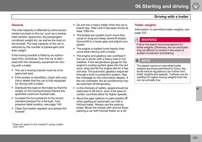
06 Starting and driving
131
Driving with a trailer
06
Genera
The loadsories mload carcombinethe towbreducedtheir we
If the towised Volered witing with
• The cappro
• If theVolvofor dr
• Distriweighspec
• Incremendpress
• Cleantowb
Trailer weightsInformation on permitted trailer weights, see page 222.
1 Does noliser hit
WARNING
Follow the stated recommendations for trailer weights. Otherwise, the car and trailer may be difficult to control in the event of sudden movement and braking.
NOTE
The stated maximum permitted trailer weights are those permitted by Volvo. Na-tional vehicle regulations can further limit trailer weights and speeds. Towbars can be certified for higher towing weights than the car can actually tow.
l
capacity is affected by extra acces-ounted on the car, such as a towbar, riers, space box, the passengers’ d weight etc. as well as the load on all. The load capacity of the car is by the number of passengers and ight.
ing bracket is fitted by an author-vo workshop, then the car is deliv-h the necessary equipment for driv- a trailer.
ar’s towing bracket must be of an ved type.
towbar is retrofitted, check with your dealer that the car is fully equipped iving with a trailer.bute the load on the trailer so that the t on the towing bracket follows the
ified maximum towball load.ase the tyre pressure to the recom-ed pressure for a full load. Tyre ure label location, see page 149. the towbar regularly and grease the
all1.
• Do not tow a heavy trailer when the car is brand new. Wait until it has been driven at least 1000 km.
• The brakes are loaded much more than usual on long and steep downhill slopes. Downshift to a lower gear and adjust your speed.
• The engine is loaded more heavily than usual when driving with a trailer.
• The engine and gearbox can overheat if the car is driven with a heavy load in hot weather. If the temperature gauge for the engine’s cooling system goes into the red zone, stop and let the engine idle for a few minutes. The automatic gearbox responds through a built-in protection system. See the message on the information display. If the car overheats, the air conditioning may be switched off temporarily.
• In the interests of safety, speed should be restricted to 80 km/h, even if the laws of certain countries allow for higher speeds.
• Move the gear selector to park position P when parking an automatic car with a hitched trailer. Always use the parking brake. Block the wheels with chocks when parking a car with hitched trailer on a hill.
t apply to the towball if using a stabi-ch.

06 Starting and driving
132
Drivi
06
Automtrailer
Parking1. App2. Mov
posi
Startin1. Mov
posi2. Rele
Steep i• Selec
tion wspeechancoole
• Do noenginnomi
• Avoidmore
ng with a trailer
atic gearbox, driving with a
on a hillly the parking brake (handbrake).e the gear selector to park tion P.
g on a hille the gear selector to driving tion D.ase the parking brake (handbrake).
nclinest an appropriate manual gear posi-hen climbing steep inclines or at low
ds. This prevents the gearbox from ging up and keeps the gearbox oil r.t use a higher manual gear than the e can handle. It is not always eco-cal to drive in high gears. driving with a trailer on inclines of than 15 %.
Diesel 1.6D engine with manual gearbox, driving with a trailerIf the car is driven with a major load in a hot climate, the engine cooling fan can be re-placed with one of a greater capacity than the standard model. Check with your nearest Volvo dealer regarding the options for your car.

06 Starting and driving
133
Towing bracket
06
Towbar
The towregularlydampergreased
If the cabar, thebe follow
W
Be surthe cor
W
If the ctowbarFollowtowbalThe towkey beCheckgreen.
NO
AlwaysKeep i
s
ball must be cleaned and greased . When a towball hitch with vibration
is used, the towball need not be .
r is equipped with a detachable tow- towball mounting instructions must
ed carefully, see page 135.
Trailer cable
An adapter is required if the car’s towing bracket has 13 pin electrics and the trailer has 7 pin electrics. Use an adapter cable ap-proved by Volvo. Make sure the cable does not drag on the ground.
ARNING
e to attach the trailer’s safety cable to rect place.
ARNING
ar is fitted with a Volvo detachable : the assembly instructions for the l section carefully.ball section must be locked with the
fore setting off. that the indicator window shows
TE
detach the towball section after use. t in the cargo area.
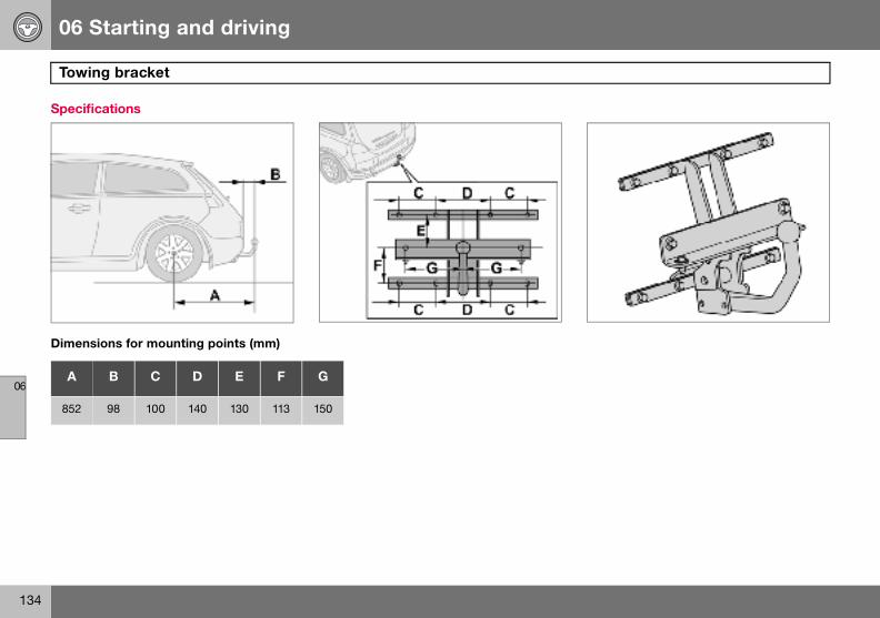
06 Starting and driving
134
Towi
06
Specifi
Dimens
A
852
ng bracket
cations
ions for mounting points (mm)
B C D E F G
98 100 140 130 113 150

06 Starting and driving
135
Detachable towbar
06
Fitting
– Remo – Check that the indicator window (3) shows red. If the window does not show red, press in (1) and turn the locking wheel anticlockwise (2) until you hear a click.
the towball
ve the guard plug. – Ensure that the mechanism is in the un-locked position by turning the key clock-wise.

06 Starting and driving
136
Deta
06
– Inserclick.
– Turn the key anticlockwise to locked posi-tion. Remove the key from the lock.
chable towbar
t the towball section until you hear a – Check that the indicator window shows green.

06 Starting and driving
137
Detachable towbar
06
NO
Checkpullingsectionremovthe pre
TE
that the towball section is secure by it up, down and back. If the towball is not fitted correctly then it must be
ed and refitted in accordance with vious instruction.
NOTE
The trailer’s safety cable must be attached to the bracket on the towbar.

06 Starting and driving
138
Deta
06
Remov
– Inserunloc
– Turn the locking wheel down fully, until it comes to a stop. Hold it in this position while pulling the towball rearward and upward.
chable towbar
ing the towball
t the key and turn it clockwise to the ked position.
– Push in the locking wheel (1) and turn it anticlockwise (2) until you hear a click.

06 Starting and driving
139
Detachable towbar
06
– Inser
t the guard plug.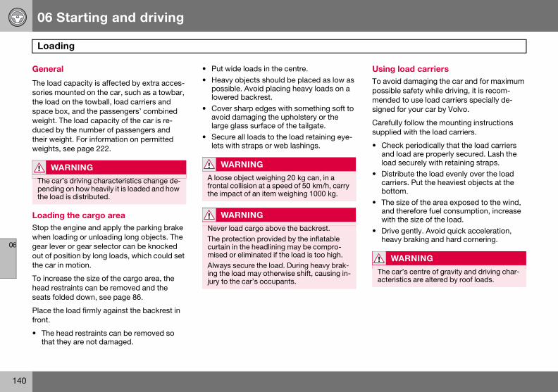
06 Starting and driving
140
Load
06
Genera
The loadsories mthe loadspace bweight. duced btheir weweights
LoadinStop thewhen logear levout of pothe car i
To increhead resseats fo
Place thfront.
• The hthat t
Using load carriersTo avoid damaging the car and for maximum possible safety while driving, it is recom-mended to use load carriers specially de-signed for your car by Volvo.
Carefully follow the mounting instructions supplied with the load carriers.
• Check periodically that the load carriers and load are properly secured. Lash the load securely with retaining straps.
• Distribute the load evenly over the load carriers. Put the heaviest objects at the bottom.
• The size of the area exposed to the wind, and therefore fuel consumption, increase with the size of the load.
• Drive gently. Avoid quick acceleration, heavy braking and hard cornering.
W
The capendinthe loa
WARNING
The car’s centre of gravity and driving char-acteristics are altered by roof loads.
ing
l
capacity is affected by extra acces-ounted on the car, such as a towbar, on the towball, load carriers and ox, and the passengers’ combined The load capacity of the car is re-y the number of passengers and ight. For information on permitted , see page 222.
g the cargo area engine and apply the parking brake
ading or unloading long objects. The er or gear selector can be knocked sition by long loads, which could set
n motion.
ase the size of the cargo area, the traints can be removed and the
lded down, see page 86.
e load firmly against the backrest in
ead restraints can be removed so hey are not damaged.
• Put wide loads in the centre.• Heavy objects should be placed as low as
possible. Avoid placing heavy loads on a lowered backrest.
• Cover sharp edges with something soft to avoid damaging the upholstery or the large glass surface of the tailgate.
• Secure all loads to the load retaining eye-lets with straps or web lashings.
ARNING
r’s driving characteristics change de-g on how heavily it is loaded and how d is distributed.
WARNING
A loose object weighing 20 kg can, in a frontal collision at a speed of 50 km/h, carry the impact of an item weighing 1000 kg.
WARNING
Never load cargo above the backrest.The protection provided by the inflatable curtain in the headlining may be compro-mised or eliminated if the load is too high.Always secure the load. During heavy brak-ing the load may otherwise shift, causing in-jury to the car’s occupants.

06 Starting and driving
141
Adjusting headlamp pattern
06
Correchand tr
A. HeadlB. Right-
The heato avoidrect patverge.
Bi-Xenon headlamps
The headlamp control should be in position (A) for left-hand traffic and position (B) for right-hand traffic.
WARNING
On cars with Bi-Xenon headlamps, their re-placement must be carried out by an au-thorised Volvo workshop. The headlamps must be handled with extreme care due to the high-voltage unit in the Xenon lamp.
t light pattern for left or right-affic
amp pattern for left-hand traffic. hand traffic.
dlamps’ projection can be adjusted dazzling oncoming traffic. The cor-tern will also better illuminate the
Halogen headlamps
The headlamp control should be in position (A) for left-hand traffic and position (B) for right-hand traffic.

142
General ................................................................................................... 144Tyre pressure .......................................................................................... 148Warning triangle and spare wheel .......................................................... 150Changing wheels .................................................................................... 151Emergency puncture repair .................................................................... 153

07WHEELS AND TYRES

07 Wheels and tyres
144
Gene
07
Driving
The tyreacteristipressurehow the
When chsame tyalso thewheels.sures splocation
DesignThe dimExample
New tyresTyres are perishable. After a few years they begin to harden at the same time as the friction capacity/char-acteristics gradually deteri-orate. For this reason, aim to get as fresh tyres as pos-
sible when you replace them. This is espe-cially important with regard to winter tyres. The week and year of manufacture, the tyre’s DOT marking (Department of Transportation), are stated with four digits, for example 1502. The tyre in the illustration was manufactured in week 15 of 2002.
Tyre ageAll tyres older than six years should be checked by an expert even if they seem un-damaged. The reason for this is that tyres age and decompose, even if they are hardly ever or never used. The function can there-fore be affected due to the tyre’s constituent materials being broken down. The tyre should then not be used. This also applies to spare tyres, winter tyres and tyres saved for future use. Examples of external signs which indicate that the tyre is unsuitable for use are cracks or discoloration.
The age of the tyre can be determined by the DOT marking, see illustration above.
20555
R1691W
ral
characteristics and tyres
s greatly affect the car’s driving char-cs. The type of tyre, dimensions, tyre and speed rating are important for
car performs.
anging tyres, ensure that tyres of the pe and dimensions, and preferably same make, are fitted to all four Follow the recommended tyre pres-ecified on the tyre pressure label, for see page 148.
ation of dimensions ensions are stated on all car tyres. of designation: 205/55R16 91 W.
Speed ratings The car is approved as a whole, which means that dimensions and speed ratings must not differ from those specified on the vehicle reg-istration document. The only exception to these conditions is winter tyres (both those with metal studs and those without). If such a tyre is chosen, the car must not be driven faster than the speed rating of the tyre (for example, class Q can be driven at a maxi-mum of 160 km/h).
Remember that traffic regulations determine how fast a car can be driven, not the speed rating of the tyres.
Note! Maximum permitted speeds indicated.Section width (mm)Ratio between section height and width (%)Radial plyRim diameter in inches (")Tyre load index (in this case 615 kg)Speed rating (in this case 270 km/h).
Q 160 km/h (used only on winter tyres)T 190 km/hH 210 km/hV 240 km/hW 270 km/hY 300 km/h

07 Wheels and tyres
145
General
07
More e
The correven webest tratyres, threar tyreThe firstthen at idifferencgreatestto the reskiddingshop if y
Wheels ing up, a
Tread depthRoad conditions with ice, slush and low tem-peratures place considerably higher de-mands on tyres than summer conditions. It is therefore recommended not to drive on win-ter tyres that have a tread depth of less than four millimetres.
Snow chainsSnow chains may only be used on the front wheels, also applies to all-wheel drive cars.
Never drive faster than 50 km/h with snow chains. Avoid driving on bare ground as this wears out both the snow chains and tyres. Never use quick-fit snow chains as the space between the brake disks and the wheels is too small.
NOTE
The legal provisions for the use of studded tyres vary from country to country.
IMPORTANT
Use Volvo genuine snow chains or equiva-lent chains designed for the car model, and tyre and rim dimensions. Consult an author-ised Volvo workshop
ven wear and maintenance
ect tyre pressure results in more ar, see page 149. To achieve the
ction and more even wear on the e regular switching of the front and s with each other is recommended. change should be after 5000 km and ntervals of 10000 km, this is to avoid es in tread depth. Tyres with the tread depth should always be fitted ar wheels to decrease the risk of . Contact an authorised Volvo work-ou are uncertain about tread depth.
should be stored lying down or hang-nd not standing up.
Tyres with tread wear indicators Tread wear indicators are narrow treadless bands across the width of the tread. On the side of the tyre are the letters TWI (Tread Wear Indicator). When the tyre’s tread depth is down to 1.6 mm, the tread depth will be level in height with the tread wear indicators. Change to new tyres as soon as possible. Remember that tyres with little tread depth provide very poor grip in rain and snow.
Winter tyres Volvo recommends winter tyres with specific winter tyre dimensions. These are stated on the tyre pressure label, for location see page 148. The tyre dimensions are depend-ent on the engine variant. When driving on winter tyres, they must be fitted to all four wheels.
Studded tyresStudded winter tyres should be run in gently for 500–1000 km so the studs settle properly into the tyres. This gives the tyre, and espe-cially the studs, a longer service life.
NOTE
Ask a Volvo dealer which rim and tyre types are most suitable.

07 Wheels and tyres
146
Gene
07
Rims a
Standard
Only useby Volvogenuinetypes ofthe rimsTighten torque w
Spare wheel Temporary Spare The spare wheel1 is only intended to be used for the short time it takes to get the ordinary wheel replaced or repaired. Replace the spare wheel with a normal wheel as soon as possible. The car’s handling may be altered by the use of the spare wheel.
Never drive faster than 80 km/h with a spare wheel on the car.
IM
The wh90 Nmnuts an
1 Certain variants and markets.
IMPORTANT
The car must never be driven fitted with more than one "Temporary Spare" wheel.
ral
nd wheel nuts
(1) and bulge acorn (2) wheel nuts
rims that are tested and approved and which are included in the Volvo
accessories range. There are two wheel nut, depending on whether are made of steel or aluminium. the wheel nuts to 90 Nm. Check the ith a torque wrench.
Steel rims – standard wheel nuts (1)Steel rims are normally mounted with the standard wheel nuts, but the bulge acorn va-riety may also be used.
Aluminium rims – bulge acorn wheel nuts (2)Only use the bulge acorn variety of nuts with aluminium rims. These differ markedly from other nut types as they have a rotating coni-cal washer.
Locking wheel nutsLocking wheel nuts can be used on both alu-minium and steel rims. If steel rims with lock-ing wheel nuts are used in combination with wheel covers, the locking wheel nut should be mounted on the bolt nearest the air valve. Otherwise the wheel cover cannot be fitted to the rim.
PORTANT
eel nuts should be tightened to . Overtightening can damage the d the bolts.
WARNING
Never use standard nuts for aluminium rims. The wheel could come loose.
NOTE
These nuts may also be used with steel rims.

07 Wheels and tyres
147
General
07
Summe
The arro
When suchangedwhich sfor examwith a tronly turnof rotatimust alwthroughswitchenever bevice verthe car’sty to for
r and winter wheels
w shows the tyre’s direction of rotation
mmer and winter wheels are the wheels should be marked with
ide of the car they were mounted on, ple L for left and R for right. Tyres
ead pattern which are designed to in one direction have the direction
on marked with an arrow. The tyre ays rotate in the same direction
out its lifespan. Tyres should only be d between front and rear positions, tween left and right-hand sides, or
sa. If the tyre is mounted incorrectly, braking characteristics and capaci-
ce rain, snow and slush out of the
way are adversely affected. Tyres with the greatest tread depth should always be fitted to the rear of the car (to decrease the risk of skidding).
Wheels should be stored lying down or hang-ing up, and not standing up.
Contact an authorised Volvo workshop if you are uncertain about tread depth.

07 Wheels and tyres
148
Tyre
07
Recom
The tyredoor pillshould hconditio
Stated o
• Tyre whee
• ECO
Tyre pressure affects travelling comfort, road noise and steering characteristics.
NO
Full loaseats w
pressure
mended tyre pressure
pressure label on the driver’s side ar shows which pressures the tyres ave at different loads and speed ns.
n the decal:
pressure for the car’s recommended l dimensionpressure
• Spare wheel pressure (Temporary Spare).
Checking the tyre pressureCheck the tyre pressure regularly.
Even after several kilometres of driving, the tyres warm up and the pressure increases. So air must not be released if the pressure is checked when the tyres are warm. While the pressure must be increased if it is too low. In-adequately inflated tyres adversely affect fuel consumption, tyre lifespan and the car’s roadholding. Driving on tyres with tyre pres-sure that is too low can also result in the tyres overheating and disintegrating.
For information on the correct tyre pressure, refer to the tyre pressure table on page 149. ("Cold tyres" means the tyres are the same temperature as the ambient temperature.)
Fuel economy, ECO pressure At speeds under 160 km/h, the general tyre pressure for full load is recommended in or-der to obtain optimum fuel economy.
TE
d in the car equates to the number of ith seatbelts.
NOTE
Tyre pressure decreases over time, this is a natural phenomenon. Tyre pressure also varies depending on ambient temperature.

07 Wheels and tyres
149
Tyre pressure
07
Tyre pr
Varianons Rear (kPa)
Max. load Front (kPa) Rear (kPa)
1.61.81.8F2.01.6D
210 250 250210 280 260
220 250 250220 280 260
2.42.4i2.0D
210 250 250210 280 260220 250 250220 280 260
T5 D5
210 250 250210 280 260220 250 250220 280 260
All 2501 2501 2501
Spare w 420 420 420
1ECO p2Tempo
essure table
t Tyre sizeSpeed (km/h)
Load, 1-3 persFront (kPa)
195/65 R15 91V 205/55 R16 91V/W 195/65 R15 91Q/T/H/V M+S 205/55 R16 91Q/T/H/V M+S
0 –160 230160+ 250
205/50 R17 93W Extra Load 215/45 R18 93W Extra Load 205/50 R17 93Q/T/H/V M+S Extra Load
0–160 240160 + 260
205/55 R16 91V/W 205/55 R16 91Q/T/H/V M+S
0–160 230160+ 250
205/50 R17 93W Extra Load 215/45 R18 93W Extra Load 205/50 R17 93Q/T/H/V M+S Extra Load
0–160 240160+ 260
205/55 R16 91 V/W 205/55 R16 91Q/T/H/V M+S
0–160 230160+ 260
205/50 R17 93W Extra Load 215/45 R18 93W Extra Load 205/50 R17 93Q/T/H/V M+S Extra Load
0–160 240160+ 270
All 0–160 2501
heel2 T125/85R16 99M 0 – 80 420
ressure, see page 148
rary Spare

07 Wheels and tyres
150
Warn
07
Warnin
Follow ting triana suitab
1. UndtrianTake
2. Lowlegs
Ensure tproperly
– Fold up the cargo area floor.– Unscrew the retaining bolt and lift out the
wheel.
Putting the spare wheel and jack into the cargo area:– Wheel wrench.– Jack and handle, secured with a tension-
ing strap.– The spare wheel is bolted down with the
rim side down using the through-bolt.
1 Certain
ing triangle and spare wheel
g triangle
he regulations for the use of a warn-gle1. Position the warning triangle in le place with regard to traffic.
o the case containing the warning gle, it is secured with Velcro straps. the warning triangle from the case.er the warning triangle’s support .he warning triangle and its case are secured in the cargo area after use.
Spare wheel and jack
The car’s original jackThe original jack2 must only be used for changing wheels. The jack’s thread should always be well greased. The spare wheel, jack and wheel wrench are found under the floor in the cargo area.
Taking out the spare wheel:A bolt runs through to secure the spare wheel.
markets. 2 Certain variants and markets.

07 Wheels and tyres
151
Changing wheels
07
Remov
Set up tchangedthe car aface.
– Takewrenin the
– Applygear,matic
– PlacewheeUse h
– There are two jacking points on each side of the car. Crank the foot of the jack down so it is pressed squarely on the ground. Check that the jack sits in the anchorage as illustrated and that the foot is posi-tioned vertically under the anchorage.
– Lift the car so that the wheel is free. Remove the wheel nuts and lift off the wheel.
ing wheels
he warning triangle if a wheel must be at a busy location. Make sure that nd jack are on a firm horizontal sur-
out the spare wheel, jack and wheel ch that are located under the carpet cargo area. the parking brake and engage first
or position P if the car has an auto- gearbox. chocks in front of and behind the ls which will remain on the ground. eavy wooden blocks or large stones.
– Cars with steel rims have removable wheel covers. Prise off the wheel cover with the end of the wheel wrench, or pull it off by hand.
– Loosen the wheel nuts ½–1 turn anticlock-wise with the wheel wrench.
07 Wheels and tyres
152
Chan
07
Fitting
– Cleanand h
– Put o– Lowe
rotate– Tight
impoenedthe to
– Put o
W
Never on the Passenraised Ensureor prefand th
ging wheels
the wheel
the contact surfaces on the wheel ub.n the wheel. Tighten the wheel nuts.r the car so that the wheels cannot .
en the wheel nuts crosswise. It is rtant that the wheel nuts are tight- properly. Tighten to 90 Nm. Check rque with a torque wrench.n the wheel cover (steel rim).
ARNING
crawl under the car when it is raised jack.gers must leave the car when it is
on the jack. that passengers wait with the car - erably a crash barrier - between them e road.

07 Wheels and tyres
153
Emergency puncture repair
07
Genera
Cars whstead eqrepair kican be ucheck aemergenelectric canister
The expiration date is located on the front of the compressor, see the illustration on page 158.
See page 158 for information on canister re-placement.
NO
The jacemerg
NOTE
The emergency puncture repair kit is only intended for sealing tyres with a puncture in the tread.
l
ich do not have a spare wheel are in-uipped with an emergency puncture
t. The emergency puncture repair kit sed to both seal the puncture and to
nd adjust the tyre pressure. The cy puncture repair kit consists of an
air compressor and an integrated with sealing liquid.
Emergency puncture repair kitThe emergency puncture repair kit1 is only in-tended to work as a temporary repair so that the car can be driven a further 200 km (max.) or to the nearest tyre centre. The sealing fluid has the capacity to effectively seal tyres which have punctures in the tread.
The sealing fluid canister should be replaced before its expiration date or after use of the puncture repair kit.
TE
k is an option on cars equipped with ency puncture repair kit.
1 Certain variants and markets.

07 Wheels and tyres
154
Emer
07
The emeed capatures in emergelarger sldamage
The emepressor in the ca
12 V socby the c
Taking repair k– Fold
forwa– Lift u
W
The secomescase ofluid w
gency puncture repair
rgency puncture repair kit has limit-city to seal tyres which have punc-the wall. Do not seal tyres with the ncy puncture repair kit if they have its, cracks, irregularities or similar .
rgency puncture repair kit with com-and tools are located under the floor rgo area.
kets for the compressor are located entre console and the rear seat.
out the emergency puncture it
away the rear edge of the floor mat, rd from the back.
p the emergency puncture repair kit.
ARNING
aling fluid may cause irritation if it into direct contact with skin. In the f contact with skin, wash away the ith soap and water.

07 Wheels and tyres
155
Emergency puncture repair
07
Inflatin
Set up tinflated
– Ensuposithose
– Screwthe bvalve
– Conn12 V
– Start ventil
– The compressor must not run for more than ten minutes. Let it cool afterwards as there is a risk of overheating.
– Objects with a volume up to 50 litres can be inflated with the compressor.
WARNING
Inhaling car exhaust fumes can result in danger to life. Never leave the engine run-ning in sealed areas or areas that lack suffi-cient ventilation.
g tyres
he warning triangle if a tyre must be in an area close to traffic.
re that the orange switch (2) is in ion 0 and take out the lead (5) and air (4) from the side compartment (3).
the air hose’s valve connection to ottom of the thread on the tyre’s air .ect the lead (5) to one of the car’s sockets.the engine. The car must be in a well-ated place.
– Start the compressor by flicking the switch (2) to position I.
– Pump up the tyre to the pressure specified on the tyre pressure label.
– Switch off the compressor, the switch (2) should be in position 0. Detach the air hose and unplug the lead. Refit the dust cap.
– Put the lead (5) and air hose (4) into the side compartment (3).
– Put the puncture repair kit back under the floor in the cargo area.

07 Wheels and tyres
156
Emer
07
Sealing
Set up trepairs mthere is
– Remoest ppuncsteerseen
– Ensuposithose
– Screwthe bvalve
– Start the compressor by flicking the switch (2) to position I. There will be a temporary pressure increase of max. 4 bar while the sealing fluid is pumped in. After approx. one minute, the pressure will drop and the gauge will indicate the correct tyre pressure.
– Pump the tyre to a pressure of between 1.8 bar and 3.5 bar. If the pressure does not reach 1.8 bar after ten minutes of pumping, the compressor must be turned off so it does not overheat.
gency puncture repair
punctured tyres
he warning triangle if emergency tyre ust be carried out in an area where
other traffic.
ve the decal (1) regarding the high-ermitted speed from the emergency ture repair kit and stick it on the ing wheel where it can be clearly by the driver.re that the orange switch (2) is in ion 0 and take out the lead (5) and air (4) from the side compartment (3).
the air hose’s valve connection to ottom of the thread on the tyre’s air .
– Connect the lead (5) to the car’s 12 V socket.
– Release the safety catch (6) and turn the orange-coloured part (7) 90 degrees to the vertical position, until a click is heard.
– Start the engine. The car must be in a well-ventilated place.
WARNING
Inhaling car exhaust fumes can result in danger to life. Never leave the engine run-ning in sealed areas or areas that lack suffi-cient ventilation.

07 Wheels and tyres
157
Emergency puncture repair
07
– Undovalvethe lethe ooriginKeepplace
– Immemuming flu
The compressor must not run for more than ten minutes. Let it cool afterwards as there is a risk of overheating.
W
Never pressoant of tor othepressostanceContac
W
You shafter thused. Tchangedriving
NOTE
The canister with sealant and hose should be replaced after use.
the air hose (4) from the tyre’s air and refit the dust cap. Disconnect ad (5) from the electrical socket. Fold range-coloured part (7) back into its al position and secure the catch (6). the emergency repair kit in a safe in the car.diately drive about 3 km, at a maxi- speed of 80 km/h, to allow the seal-id to seal the tyre well.
Check the tyre pressure again:
– Connect the air hose (4) to the air valve on the tyre. Connect the lead (5) to the 12 V socket. Read the pressure on the com-pressor. If the tyre pressure is below 1.3 bar, the tyre has not been sufficiently well sealed. Under these circumstances your journey should not be continued. Contact a tyre centre.
– If the tyre pressure is higher than 1.3 bar, the tyre should be pumped up to the pressure stated on the tyre pressure label, for location see page 148. Relieve pres-sure with the reduction valve (8) if the tyre pressure is too high.
– Switch off the compressor, the switch (2) should be in position 0. Detach the air hose and unplug the lead. Refit the dust cap.
– Put the lead (5) and air hose (4) into the side compartment (3).
– Put the puncture repair kit back under the floor in the cargo area.
ARNING
stand next to the tyre when the com-r is running. Be particularly observ-he tyre walls. If cracks, irregularities r damage appears, turn off the com-r immediately. Under these circum-s your journey should not continue. t an authorised tyre centre.
ARNING
ould not drive faster than 80 km/h e emergency tyre repair kit has been he temporarily sealed tyre must be d as soon as possible (maximum
distance: 200 km).
NOTE
Do not raise the orange-coloured part (7) when only the compressor is to be used for inflation.

07 Wheels and tyres
158
Emer
07
Replac
The seabefore itlabel (1)the canihose (10
This repauthoristhe instr
– Unscrew and remove the canister (6).– Check that the seal (7) on the new canister
is not damaged. Screw in the canister.– Refit the case (3). Check that the case is
correctly fitted. Screw it on with the screws (2).
– Affix the speed label (4) and new date label (1) to the tyre repair kit.
Treat the removed canister as hazardous waste.IM
Read tof the c
gency puncture repair
ing the sealing fluid canister
ling fluid canister should be replaced s expiration date, see the date , or after puncture repair. After use, ster (6) with holder (8) and air ) should be replaced.
lacement can be carried out by an ed Volvo workshop or by following uctions.
Replacing the canister before the expiration date has been reached– Undo the two screws (2) on the orange-
coloured case (3).– Remove the speed label (4) and date
label (1), and open the safety catch (5). Loosen the case (3) and take it off.
PORTANT
he safety instructions on the bottom anister.
WARNING
Ensure the compressor is not connected to the 12 V socket when the canister is re-placed.

07 Wheels and tyres
159
Emergency puncture repair
07
Replacuse– Undo
colou– Remo
label Loos
– PushcanisRemo
– Pull o– Wipe
or sc– Fit a n
fitted– Chec
is notthe cuntil a
– Refit correscrew
– Affix label
The emped as no
ing the canister and hose after
the two screws (2) on the orange-red case (3).ve the speed label (4) and date (1), and open the safety catch (5). en the case (3) and take it off. down the button (8) while turning the ter (6) and the holder (9) clockwise. ve them.ut the air hose (10). off remaining sealing fluid with a rag rape it away if it is has already dried.ew air hose (10). Check that it is
correctly.k that the seal (7) on the new canister damaged. Screw the holder (9) onto anister (6) and turn it anticlockwise click is heard.
the case (3). Check that the case is ctly fitted. Screw it on with the s (2).
the speed label (4) and new date (1) to the tyre repair kit.ty canister and air hose can be treat-rmal waste.

160
Cleaning ................................................................................................. 162Touching up paintwork ........................................................................... 165Rustproofing .......................................................................................... 166

08CAR CARE

08 Car care
162
Clea
08
Washin
Wash thUse carto corro
• Do noWashcauseWashwater
• Thorothe c
• RinseWhenthat tnot cnot s
• Washplent
• If thecar u
• Dry tha wat
• Cleansoap
RemovWash awwork ascontain
Lightly depress the brake pedal now and then when driving long distances in rain or slush. This heats and dries the brake pads. Do the same thing after starting in very damp or cold weather.
Exterior plastic partsA special cleaning agent, available from Vol-vo dealers, is recommended for cleaning ex-terior plastic parts. Never use strong stain re-movers.
IMPORTANT
Washing by hand is gentler to the paintwork than an automatic car wash. Paintwork is also more sensitive when it is new. For this reason, handwashing is recommended dur-ing the first few months with a new car.
ning
g the car
e car as soon as it becomes dirty. shampoo. Dirt and road salt can lead sion.
t park the car in direct sunlight. ing a car with hot paintwork can permanent paintwork damage. the car in a car wash with waste separator.ughly rinse dirt off the underbody of
ar. the entire car to remove loose dirt. using a pressure washer: Make sure
he nozzle of the pressure washer is loser than 30 cm to the bodywork. Do pray directly onto the locks. using a sponge, car shampoo and
y of lukewarm water. dirt is difficult to dislodge, wash the sing a cold degreasing agent.e car using a clean, soft chamois or er scraper. the wiper blades with a lukewarm
solution or car shampoo.
ing bird droppingsay bird droppings from the paint-
soon as possible. Bird droppings chemicals that affect and discolour
paintwork very quickly. This discoloration can only be removed by a specialist.
Automatic car washes An automatic car wash is a simple and quick way of washing the car, but it can never re-place a proper handwashing. The brushes of an automatic car wash cannot reach everywhere.
WARNING
Always have the engine cleaned by a work-shop. There is a risk of fire if the engine is hot.
NOTE
Outside lighting such as headlamps, fog lamps and rear lamps may temporarily have condensation on the inside of the lens. This is a natural phenomenon, all outside lighting is designed to withstand this. Condensation is normally vented out of the lamp when it has been switched on for a time.
WARNING
Always test the brakes after washing, so that moisture and corrosion do not affect the brake linings and impair the brakes.
08 Car care
163
Cleaning
08
PolishiPolish aor to giv
The car is at leasbe waxewax the
Wash anbegin poand tar swhite spmoved ucar pain
Polish filiquid orthe packcontain
Cleaning the interior
Treating stains on fabric upholsteryA special cleaning agent, available from Vol-vo dealers, is recommended for cleaning the fabric upholstery. Other chemicals can impair the fire retardant qualities of the upholstery.
Treating stains on leather upholsteryVolvo’s leather upholstery is equipped with surface protection against dirt. Cleaning re-protects the leather but grease and dirt dis-solves the surface protection. There is a comprehensive programme for the care and maintenance of leather upholstery. Volvo of-fers a leather product for cleaning and treat-ing the upholstery by which means the leath-er regains its protective layer.
IM
Paint tprotecdamagcausedVolvo w
IMPORTANT
Sharp objects and Velcro may damage the fabric upholstery.
IMPORTANT
Never use strong solvents. Such products may damage fabric, vinyl and leather uphol-stery.
ng and waxing nd wax the car if the paintwork is dull e the paintwork extra protection.
does not need to be polished until it t one year old. However, the car can d before this time. Do not polish or car in direct sunlight.
d dry the car thoroughly before you lishing or waxing. Clean off asphalt tains using Volvo tar remover or irit. More stubborn marks can be re-sing fine rubbing paste designed for
twork.
rst with a polish and then wax with solid wax. Follow the instructions on aging carefully. Many preparations
both polish and wax.
Cleaning door mirrors and front side windows with water-repellent surface (option)Never use products such as car wax, de-greaser or similar on mirror/glass surfaces as this could ruin their water-repellent proper-ties.
Take care when cleaning so as not to dam-age the glass surface.
To avoid damaging glass surfaces when re-moving ice – only use plastic ice scrapers.
There is natural wear of the water-repellent coating.
Treatment with a special finishing agent available from Volvo dealers is recommend-ed in order to maintain the water-repellent properties. This should be used first after three years and then each year.
PORTANT
reatment such as preserving, sealing, tion, lustre sealing or similar could e the paintwork. Paintwork damage by such treatment is not covered by arranty.

08 Car care
164
Clea
08
To achiecleaningcream tw
Ask youCare pro
Washinuphols– Pour
spon– Work
move– Dab t
Allownot ru
– Wipeallow
Protectstery– Pour
creama thinmove
– Now 20 m
IM
Note thwhen dmay di
ning
ve best results Volvo recommends and application of the protective o to four times per year.
r Volvo dealer about Volvo’s Leather duct
g instructions for leather tery the leather cleaner on the dampened ge and squeeze out a strong foam. the dirt away with gentle circular ments.he sponge accurately on the stains. the sponge to absorb the stain. Do b.
off with soft paper or a cloth and the leather to dry completely.ive treatment of leather uphol-
a small amount of the protective on the felted cloth and massage in
layer of cream with gentle circular ments on the leather.allow the leather to dry for inutes before use.
– The leather has now been given improved protection against stains and a UV filter.
Treating stains on interior plastic parts and surfacesA special cleaning agent, available from Vol-vo dealers, is recommended for cleaning in-terior plastic parts and surfaces. Do not scrape or rub stains. Never use strong stain removers.
Cleaning seatbelts Use water and a synthetic detergent. A spe-cial textile cleaning agent is available from your Volvo dealer. Make sure the seatbelt is dry before allowing it to retract.
PORTANT
at materials with colour that runs ry (new jeans, suede garments etc.)
scolour the upholstery material.

08 Car care
165
Touching up paintwork
08
Paintw
Paint is proofingregularlyaged paately. Thdamagemarks o
Colour
Data pla
It is impThe colodata pla
coat, you can paint straight after cleaning the damaged area.
If the stone chip has penetrated to the bare metal– Apply a piece of masking tape over the
damaged surface. Then remove the tape to remove any loose paint.
– Stir the primer well and apply using a fine brush or a matchstick. Apply paint using a brush once the primer is dry.
– For scratches, proceed as above, but mask around the damaged area to protect the undamaged paintwork.
– After a few days, polish the touched-up areas. Use a soft rag and a small amount of lapping paste.
ork
an important part of the car’s rust- and should therefore be checked . To avoid the onset of rust, dam-intwork should be rectified immedi-e most common types of paintwork are stone chips, scratches, and n the edges of wings and doors.
code
te
ortant that the correct colour is used. ur code number (1) is shown on the te, see page 220.
Stone chips and scratches
Before touching up paintwork, the car must be clean and dry and at a temperature above 15 �C.
Materials• Primer in a can• Paint in a can or touch-up pen• Brush• Masking tape
Minor stone chips and scratches If the stone chip has not penetrated to the bare metal and there is an undamaged colour

08 Car care
166
Rust
08
Inspec
Your caand comParts ofsheet mwear-rethin, pensprayedclosed s
Maintain
• Keepbodynozzlsurfa
• Reguproof
The car’quire treAfter thithree-yetreatmevo work
proofing
tion and maintenance
r has already received a thorough plete rustproofing at the factory.
the body are made of galvanised etal. The underbody is protected by a sistant anti-corrosion compound. A etrating rustproofing fluid was into the members, cavities and ections.
ing the car’s rustproofing.
the car clean. Hose down the under-. If using a pressure washer, keep the e at least 30 cm from the painted ces.larly check and touch-up the rust-ing treatment as necessary.s rustproofing does not normally re-atment for approximately 12 years. s period, it should be treated at ar intervals. If the car needs further nt, please contact an authorised Vol-shop.

08 Car care
167
08

168
Volvo service .......................................................................................... 170Self-maintenance ................................................................................... 171Bonnet and engine compartment .......................................................... 172Diesel ..................................................................................................... 173Oils and fluids ........................................................................................ 174Wiper blades .......................................................................................... 178Battery .................................................................................................... 179Replacing bulbs ..................................................................................... 181Fuses ...................................................................................................... 187

09MAINTENANCE AND SERVICE

09 Maintenance and service
170
Volvo09
Volvo s
Before toughly taccordaulations
To keeppossiblegrammety Bookshop cawork. Vospecial tee the h
SpeciaCertain car’s eleformed developways cobefore bthat affe
Corporation will not disclose the stored infor-mation without consent. However, Volvo Car Corporation may be forced to disclose the in-formation due to national legislation. Volvo Car Corporation and authorised Volvo work-shops may also read and use the informa-tion.
Adverse driving conditions Check the oil level more frequently for long journeys:
• Towing a caravan or trailer• In mountainous regions• At high speeds• In temperatures colder than –30 �C or
hotter than +40 �C.Also check the oil level more often if the car is often driven short distances (less than 10 km) when temperatures are low (below +5 �C).
This can produce abnormally high oil temper-ature or oil consumption.
IM
For thefollow Warran
service
ervice programme
he car left the factory, it was thor-est driven. It was checked again in nce with Volvo Car Corporation reg- before it was handed over to you.
your Volvo as safe and reliable as , follow the Volvo service pro- specified in the Service and Warran-let. Have an authorised Volvo work-rry out service and maintenance lvo workshops have the personnel,
tools and service literature to guaran-ighest quality of service.
l service measuresservice measures which affect the ctrical system can only be per-
using electronic equipment specially ed for your car. For this reason, al-ntact an authorised Volvo workshop eginning or performing service work cts the electrical system.
Installing accessoriesThe incorrect connection and installation of accessories can negatively affect the car’s electrical system. Certain accessories only function when the appropriate software has been programmed into the car’s electrical system. Always contact an authorised Volvo workshop before installing accessories which are connected to or affect the electri-cal system.
Recording vehicle data One or more of the computers in your Volvo are capable of recording detailed informa-tion. This information is intended for use in research to enhance safety and for diagnos-ing faults in some of the in-car systems. The data may include details regarding seatbelt use by the driver and passengers, the func-tions of various vehicle systems and mod-ules, and status information about the en-gine, throttle, steering, brakes and other sys-tems. This data can also include details of the way the car is driven. This type of infor-mation can include, without being limited to, specific details such as vehicle speed, the use of the brake and accelerator pedals and steering wheel position. This latter type of data can be stored for a limited period while the car is being driven and subsequently dur-ing a collision or a near-collision. Volvo Car
PORTANT
Volvo warranty to apply, check and the instructions in the Service and ty Booklet.

09 Maintenance and service
171
Self-maintenance 09
Before
BatteryCheck tconnect
Never dgine is r
Never utery. Theed when
The battsive andhandle table wa
W
High ovoltagegerousbe swipartmeDo notcoils whot.
starting work on the car
hat the battery cables are correctly ed and tightened.
isconnect the battery when the en-unning (e.g. if replacing the battery).
se a quick charger to charge the bat- battery cables must be disconnect- charging the battery.
ery contains acid that is both corro- toxic. It is therefore important to he battery in an environmentally-suit-y. Let your Volvo dealer assist you.
Check regularly Check the following at regular intervals, for example, when refuelling:
• Coolant – The level must be between the MIN and MAX marks on the expansion tank.
• Engine oil – The level must be between the MIN and MAX marks.
• Power steering fluid – The level must be between the MIN and MAX marks.
• Washer fluid – The reservoir should be well filled. Use washer antifreeze at tempera-tures around freezing.
• Brake and clutch fluid – The level must be between the MIN and MAX marks.
ARNING
utput from the ignition system. The in the ignition system is highly dan-. The ignition must therefore always tched off for work in the engine com-nt. touch the spark plugs or ignition hen the ignition is on or the engine is
WARNING
Bear in mind that the radiator fan may start automatically some time after the engine has been switched off.Always have the engine cleaned by a work-shop. There is a risk of fire if the engine is hot.

09 Maintenance and service
172
Bonn09
Openin
To open
– Pull tdashrelea
– Inserfront safet
– Open
8. Brake and clutch fluid reservoir (right-hand drive)
9. Filler opening for engine oil1
10.Brake and clutch fluid reservoir (left-hand drive)
11.Battery12.Relay and fuse box13.Air filter1
W
Checkclosed
et and engine compartment
g the bonnet
the bonnet:
he handle on the far left under the board. You will hear when the catch ses.t your hand under the centre of the edge of the bonnet and press the y catch to the right. the bonnet.
Engine compartment1. Washer fluid reservoir (4-cyl.) Illustration
is slightly simplified2. Coolant expansion tank3. Reservoir for the power steering fluid
(concealed behind the headlamp)4. Engine oil dipstick1
5. Radiator6. Radiator fan7. Washer fluid reservoir (5-cyl.)
ARNING
that the bonnet locks properly when .
1 Dependent on engine variant.

09 Maintenance and service
173
Diesel 09
Fuel sy
Diesel mstandardcontamiphur pafuel fromdiesel o
At low teaffin prewhich cjor oil cograde ding. Thistures antate.
The riskduced iffuelling,filler pippaintwogent and
The fuel filter must be drained at the intervals specified in the Service and Warranty Book-let or if you suspect that the car has been filled with contaminated fuel.
IMPORTANT
Certain special additives remove the water separation in the fuel filter.
stem
ust fulfil the EN 590 or JIS K2204 s. Diesel engines are sensitive to
nants, such as high volumes of sul-rticles for example. Only use diesel a well-known producers. Never use
f dubious quality.
mperatures (–40 �C to –6 �C), a par-cipitate may form in the diesel fuel, an lead to ignition problems. The ma-mpanies produce a special winter-
iesel for temperatures around freez- fuel is less viscous at low tempera-d reduces the risk of paraffin precipi-
of condensation in the fuel tank is re- the tank is kept well filled. When re- check that the area around the fuel e is clean. Avoid spilling fuel onto the rk. Wash off any spillage with deter- water.
Empty tankNo special procedures are required if the tank runs dry. The fuel system is bled auto-matically if the ignition switch is kept in position II for approx. 60 seconds before the start attempt.
Draining condensation from the fuel filter The fuel filter separates condensation from the fuel. Condensation can disrupt engine operation.
IMPORTANT
Diesel type fuels which must not be used: special additives, Marine Diesel Fuel, fuel oil, RME (Rape Methyl Ester) and vegetable oil. These fuels do not fulfil the requirements in accordance with Volvo recommendations and generate increased wear and engine damage that is not covered by the Volvo warranty.
IMPORTANT
For model year 2006 or later the sulphur content must be a maximum of 50 ppm.

09 Maintenance and service
174
Oils 09
Enginegrade
Using opermitteditions, higher gSee pag
olvo recommends oil products. hange the oil and oil filter in accordance ith the intervals specified in the Service and arranty Booklet.
IM
Alwaysthe engoil levelarly. Tgrade the oil
IMPORTANT
In order to fulfil the requirements for the en-gine’s service intervals all engines are filled with a specially adapted synthetic engine oil at the factory. The choice of oil has been made very carefully with regard to service life, starting characteristics, fuel consump-tion and environmental impact. An ap-proved engine oil must be used in order that the recommended service intervals can be applied. Only use a prescribed grade of oil (see the engine compartment decal) for both filling and oil change, otherwise you will risk affecting service life, starting char-acteristics, fuel consumption and environ-mental impact. Volvo Car Corporation disclaims all warranty liability if engine oil of the prescribed grade and viscosity is not used.
and fluids
compartment decal for oil
il of a higher than specified grade is d. If the car is driven in adverse con-Volvo recommends using an oil of a rade than that specified on the decal. e 226.
Checking the engine oil and oil filter
Dipstick, petrol engines
Dipstick, diesel engines
VCwW
PORTANT
use oil of the prescribed grade, see ine compartment decal. Check the l frequently and change the oil regu-he engine will be damaged if lower oil is used or if the car is driven with level too low.

09 Maintenance and service
175
Oils and fluids 09
Volvo uslow oil leants havthe lampants havdriver isthe centdisplay ants. Comore inf
Checkincially imchange.specifiechanges
Volvo reevery 2 ments astarting.if taken switchethe levehad time
Checking the oil in a warm engine:– Park the car on a level surface, switch off
the engine and wait 10–15 minutes to allow the oil time to run back to the sump.
– Wipe the dipstick clean before checking the level.
– Check the oil level using the dipstick. The level must be between the MIN and MAX marks.
If the level is close to the MIN mark, start by topping up with 0.5 litres. Top up until the oil level is nearer the MAX than the MIN mark on the dipstick. See page 226–227 for capacities.
WARNING
Do not spill oil onto the hot exhaust mani-fold due to the risk of fire.
IMPORTANT
Never fill above the MAX mark. Oil con-sumption may increase if too much oil is poured into the engine.
es different systems for warning of vel or low oil pressure. Certain vari-e an oil pressure sensor, and then for oil pressure is used. Other vari-e an oil level sensor, and then the informed via the warning symbol in re of the instrument unit as well as by texts. Certain models have both vari-ntact an authorised Volvo dealer for ormation.
g the oil level in a new car is espe-portant before the first scheduled oil The Service and Warranty Booklet s the odometer readings for oil .
commends checking the oil level 500 km. The most accurate measure-re made on a cold engine before The measurement will be inaccurate immediately after the engine is d off. The dipstick will indicate that l is too low because the oil has not to flow down into the oil sump.
Checking the oil
The oil level must be within the area marked on the dipstick.
Checking the oil in a cold engine:– Wipe the dipstick clean before checking
the level.– Check the oil level using the dipstick. The
level must be between the MIN and MAX marks.
– If the level is close to the MIN mark, start by topping up with 0.5 litres. Top up until the oil level is nearer the MAX than the MIN mark on the dipstick. See page 226–227 for capacities.

09 Maintenance and service
176
Oils 09
Washe
Location
The winshare a
– Filler – Filler Add wathat thereservoipage 23
For capacities, see page 230.
Check the coolant regularlyThe level must lie between the MIN and MAX marks on the expansion tank. If the system is not filled sufficiently, high local temperatures could occur, causing a risk of damage (cracks) to the cylinder head. Top up the coolant when the level falls to the MIN mark.
NO
Mix thefilling t
WARNING
Coolant can be very hot. If the coolant re-quires topping up when the engine is at op-erating temperature, unscrew the expansion tank cap slowly to gently release the overpressure.
NOTE
The engine must only be run with a well-filled cooling system. High temperatures can occur, causing a risk of damage (cracks) to the cylinder head.
and fluids
r fluid, topping up
of washer fluid reservoir.
dscreen and headlamp washers common reservoir.
cap on 4-cylinder engines and diesel.cap on 5-cylinder engines.sher antifreeze during the winter so fluid does not freeze in the pump, r and hoses. For capacities, see 1.
Checking and topping up the coolant
When topping up the coolant, follow the in-structions on the packaging. It is important that the mixture of coolant concentrate and water is correct for the prevailing weather conditions. Never top up with water only. The risk of freezing increases with both too little and too much coolant concentrate.
TE
washer antifreeze and water before he reservoir.
IMPORTANT
Always use coolant with anti-corrosion agent as recommended by Volvo. New cars are filled with coolant that can withstand temperatures down to approximately –35 �C.

09 Maintenance and service
177
Oils and fluids 09
Checkiand clu
The brareservoithe MINregularlyyear or a
See thegrade o
The fluiddriven inbraking,ical clim
Checking and topping up the power steering fluid
The fluid does not require changing. For ca-pacities and recommended fluid grade, see page 231.
If a fault should arise in the power steering system or if the car is without power and must be towed, it can still be steered. How-ever, the steering will be much heavier than normal and it will require more effort to turn the steering wheel.
1 Locatioright-ha
NOTE
Check the level frequently.
ng and topping up the brake tch fluid
ke and clutch fluid have a common r1. The fluid level must be between and MAX marks. Check the level . Change the brake fluid every other t every other regular service.
capacities and recommended fluid n page 231.
should be changed annually on cars conditions requiring hard, frequent such as driving in mountains or trop-ates with high humidity.
n dependent on whether car is left or nd drive.
WARNING
If the brake fluid is under the MIN level in the brake fluid reservoir, do not drive further before topping up the brake fluid.The reason for the loss of brake fluid must be investigated.

09 Maintenance and service
178
Wipe09
Replac
– Turn – Press
bladeparal
– Slide"click
– Chec– Fold
Replacing the wiper blades, rear window
– Fold out the wiper arm.– Detach the wiper blade by moving it
straight out from the wiper arm.– Press the new wiper blade into position.
Check that it is firmly installed.– Lower the wiper arm.
NO
The wiblade othe oth
r blades
ing the wiper blades
up the wiper arm. the button located on the wiper mounting and pull straight out (1), lel with the wiper arm. in (2) the new wiper blade until a " is heard.k (3) that the blade is firmly installed.down the wiper arm.
TE
per blades are different lengths. The n the driver’s side is longer than on er side.

09 Maintenance and service
179
Battery 09
Battery
There mThey are
The servinfluencstarts, dditions a
IM
Alwaystery wa
NO
An expenvironcontain
WARNING
atteries can generate oxyhydrogen gas, hich is highly explosive. One spark, which an be generated if you connect the jump
eads incorrectly, is sufficient to make the attery explode.The battery contains sul-huric acid, which can cause serious burns.
f the acid comes into contact with eyes, kin or clothing, flush with large quantities f water. If acid splashes into the eyes, seek edical attention immediately.
NOTE
he life of the battery is shortened if it be-omes discharged repeatedly
care
ay be two different types of battery. fully interchangeable with each other.
ice life and function of the battery is ed by factors such as the number of ischarging, driving style, driving con-nd climatic conditions.
For the battery to function satisfactorily:
• Regularly check that the electrolyte level is correct (A) and never fill above the level mark.
• Check all of the cells. Use a screwdriver to remove the cell caps (or the cover).
• If necessary, top up with distilled water to the battery’s maximum mark.
• Fit the cell caps (or the cover) firmly.
PORTANT
use distilled or deionised water (bat-ter).
TE
ended battery must be recycled in an mentally responsible manner as it s lead.
BwclbpIsom
Tc

09 Maintenance and service
180
Batte09
Symbo Replacing the battery
Removing the battery– Switch off the ignition and remove the key.– Wait at least 5 minutes before touching
any electrical terminals. This allows time for the information in the car’s electrical system to be stored in the different control modules.
– Remove the cover.– Disconnect the negative battery lead.– Disconnect the positive battery lead.– Undo the front wall of the battery box
using a screwdriver.– Release the clamp securing the battery.– Remove the battery.
Fitting the battery– Fit the battery into position.– Fit the clamp securing the battery.– Reinstall the front wall of the battery box.– Connect the positive lead.– Connect the negative lead.– Refit the cover over the battery.
ry
ls on the battery Use protective goggles.
Further information in the owner’s manual.
Store the battery out of the reach of children.
The battery contains corro-sive acid.
Avoid sparks and naked flames.
Risk of explosion.

09 Maintenance and service
181
Replacing bulbs 09
Genera
All bulb
The follosource lble for r
• Gene• Read• Indic
ing• High-• Bi-Xe
Unplug the connector by pressing down the clip with a thumb (3) while moving out the connector (4) with the other hand.Lift out the lamp housing and place it on a soft surface to avoid scratching the lens.
itting the lamp housing:Plug in the connector and refit the lamp housing and locking pin. Check that the pin is correctly inserted.Check the lighting.
he lamp housing must be plugged in and ecured in place before the lighting is turned n or the ignition key inserted into the ignition witch.
W
On carplacemthorisemust bthe hig
IM
Never your fingers arreflecto
l
specifications are given on page 236.
wing list contains bulbs and point-amps that are specialised or unsuita-eplacement except at a workshop:
ral interior lighting in the roofing lamps and glovebox lightingator, door mirror and approach light-
level brake lightnon headlamp
Replacing front bulbs
All front bulbs (except for fog lamps) are re-placed by first removing the lamp housing from the engine compartment.
Removing the lamp housing:– Remove the ignition key and turn the light
switch to position 0.– Withdraw the lamp housing’s locking
pin (1).– Pull the lamp housing to the side and then
forward (2) .
–
–
F–
–Tsos
ARNING
s with Bi-Xenon headlamps the re-ent must be carried out by an au-d Volvo workshop. The headlamps e handled with extreme care due to h-voltage unit in the Xenon lamp.
PORTANT
touch the glass part of the bulbs with gers. Grease and oil from your fin-e vaporised by the heat, coating the r and then causing damage.
IMPORTANT
Do not pull the electrical cable, only the connector.

09 Maintenance and service
182
Repl09
Dipped
Remov– Remo– Bend
cover– Unplu– Relea
First,out a
– Pull o– Refit
Main beam
– Remove the entire lamp housing.– Left-hand headlamp:
Turn the bulb holder anticlockwise. Right-hand headlamp: Turn the bulb holder clockwise.
– Withdraw the bulb holder and replace the bulb.
– Refit the bulb holder. It can only be refitted in one position.
– Refit the lamp housing.
acing bulbs
beam
ing the cover and bulb:ve the entire lamp housing.
aside the catches and remove the .g the connector from the bulb.se the spring clip securing the bulb.
press it to the left to release it, then nd down.ut the bulb.the lamp housing.
Fitting a new bulb– Fit the new bulb. It can only fit in one
position.– Press the spring clip up and then slightly
to the right so that it clicks into place.– Press the connector back on.– Refit the plastic cover.– Refit the lamp housing.

09 Maintenance and service
183
Replacing bulbs 09
Positio
– Withdnot pelectr
– Repla– Press
be re
Side marker lamps
– Twist the bulb holder anticlockwise and withdraw it. Replace the bulb.
– Refit the bulb holder. It can only fit in one position.
n/parking lamps
raw the bulb holder using pliers. Do ull out the bulb holder by pulling the ical cable.ce the bulb. the bulb holder back on. It can only fitted in one position.
Direction indicators
– Twist the bulb holder anticlockwise and remove it.
– To remove the bulb from the bulb holder, press the bulb in and turn it anticlockwise.
– Fit a new bulb and refit the bulb holder into the lamp housing.

09 Maintenance and service
184
Repl09
Fog lam
– Switckey to
– Remohous
– Remolamping.
– Unplu– Turn – Fit th– Plug – Secu
and p
ocation of the bulbs in the rear lamp luster
ulb holder
. Brake light
. Position/parking and fog lamps
. Position/parking lamps
. Indicator
. Reversing lamp
. Position/parking lamps
NOTE
If the error message BULB FAILURE/CHECK STOP LAMP remains after a faulty bulb has been replaced then consult an au-thorised Volvo workshop.
acing bulbs
ps
h off all lights and turn the ignition position 0.ve the panel from around the lamp
ing.ve the two Torx screws securing the
housing and take out the lamp hous-
g the connector from the bulb.the bulb anticlockwise and pull it out.e new bulb and turn it clockwise.in the connector to the bulb.re the lamp housing with the screws ress the panel back into place.
Removing the bulb holder
– All bulbs in the rear lamp cluster can be replaced from inside the cargo area. Switch off all lights and turn the ignition key to position 0.
– Remove the covers (A or B) in the left/right-hand panel to access the bulbs. The bulbs are located in separate bulb holders.
– Unplug the connector from the bulb hold-er.
– Press the catches together and pull out the bulb holder.
– Replace the bulb and plug in the connec-tor. Press the bulb holder into place and refit the cover (A or B).
Lc
B
123456

09 Maintenance and service
185
Replacing bulbs 09
Numbe
– Switckey to
– Remo– Detac– Repla– Refit
Courtesy lighting
– There is courtesy lighting under the dash-board on the driver and passenger sides.
– Insert a screwdriver and gently turn so that the lens detaches.
– Remove the blown bulb.– Fit a new bulb.– Refit the lens.
r plate lighting
h off all lights and turn the ignition position 0.ve the screws with a screwdriver.h the lens carefully.ce the bulb.and screw in the lens.
Reflector
The reflector is secured with clips and is pressed in. It can only fit in one position.
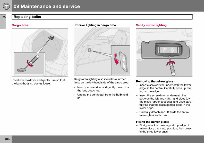
09 Maintenance and service
186
Repl09
Cargo
Insert a the lamp
anity mirror lighting
emoving the mirror glass:Insert a screwdriver underneath the lower edge, in the centre. Carefully prise up the lug on the edge. Insert the screwdriver underneath the edge on the left and right-hand sides (by the black rubber sections), and prise care-fully so that the glass comes loose in the lower edge.Carefully detach and lift aside the entire mirror glass and cover.
itting the mirror glass:First, press the three lugs at top edge of mirror glass back into position, then press in the three lower ones.
acing bulbs
area
screwdriver and gently turn so that housing comes loose.
Interior lighting in cargo area
Cargo area lighting also includes a further lamp on the left-hand side of the cargo area.
– Insert a screwdriver and gently turn so that the lens detaches.
– Unplug the connector from the bulb hold-er.
V
R–
–
–
F–

09 Maintenance and service
187
Fuses 09
Genera
All electfused tofrom daloading.
The fusecar:
• Relay• Relay
ment
ReplacIf an elenot worknent’s fublew.
– Lookfuse.
– Pull oto se
– If thisfuse o
Each fusfuses. Ifthere is case, coto have
l
rical functions and components are protect the car’s electrical system mage by short circuiting and over-
s are in two different locations in the
/fuse box in the engine compartment/fuse box in the passenger compart-.
ement ctrical component or function does , it may be because the compo-se was temporarily overloaded and
in the fuse diagram to locate the
ut the fuse and check from the side e whether the curved wire has blown. is the case, replace it with a new f the same colour and amperage.e box has space for several spare
the same fuse fails repeatedly then a fault in the component. In which ntact an authorised Volvo workshop the system checked.

09 Maintenance and service
188
Fuse09
Relay/f
The fuseto replacthe sam
• Fuse• Fuse
shouwork
• Fusemay oVolvo
On the isist rem
s
use box in the engine compartment
box has 36 fuse positions. Be sure e a blown fuse with a new fuse of
e colour and amperage.
s 19–36 are of the "Mini Fuse" type.s 7–18 are of the "JCASE" type and ld be replaced by an authorised Volvo shop.s 1–6 are of the "Midi Fuse" type and nly be replaced by an authorised workshop.nside of the cover are tweezers to as-oving and fitting fuses.
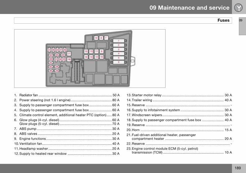
09
09 Maintenance and service
189
Fuses
1. Radi2. Pow3. Sup4. Sup5. Clim6. Glow
Glow7. ABS8. ABS9. Engi10.Vent11.Hea12.Sup
............................................................ 30 A
............................................................ 40 A
.................................................................. -ent system .......................................... 30 A............................................................ 30 Ar compartment fuse box ..................... 40 A
.................................................................. -
............................................................ 15 Aal heater, passenger r ......................................................... 20 A.................................................................. -ule ECM (5-cyl. petrol) ........................................................... 10 A
ator fan .............................................................................. 50 Aer steering (not 1.6 l engine) ........................................ 80 Aply to passenger compartment fuse box ...................... 60 Aply to passenger compartment fuse box ...................... 60 Aate control element, additional heater PTC (option) ..... 80 A plugs (4-cyl. diesel) ................................................... 60 A plugs (5-cyl. diesel) ................................................... 70 A
pump ......................................................................... 30 A valves ........................................................................ 20 Ane functions ................................................................ 30 Ailation fan.................................................................... 40 Adlamp washer .............................................................. 20 Aply to heated rear window ........................................... 30 A
13.Starter motor relay14.Trailer wiring .........15.Reserve ................16.Supply to infotainm17.Windscreen wipers18.Supply to passenge19.Reserve ................20.Horn .....................21.Fuel-driven addition
compartment heate22.Reserve ................23.Engine control mod
transmission (TCM)

09
09 Maintenance and service
190
Fuse
24.Hea(5-c
25.Rese26. Ignit27.A/C 28.Rese29.Fron30.Eng31.Volta32. Injec
charand
33.Lamengiheat
34. Ignitfuel climEGR
35.EngPTCmod(1.8/(5-cpresEGR
36.Engipeda
s
ted fuel filter, PTC element oil trap yl. diesel) ..................................................................... 20 Arve ...................................................................................-
ion switch ................................................................... 15 Acompressor ................................................................ 10 Arve ...................................................................................-t fog lamp ................................................................... 15 A
ine control module ECM (1.6 l petrol, 2.0 l diesel) ...........3 Age regulator, alternator 4-cyl. ..................................... 10 Ators (5-cyl. petrol), lambda-sond (4-cyl. petrol), ge air cooler (4-cyl. diesel), mass air flow sensor turbo control (5-cyl. diesel) ......................................... 10 Abda-sond and vacuum pump (5-cyl. petrol), ne control module (5-cyl. diesel), diesel filter er (4-cyl. diesel) .......................................................... 20 Aion coils (petrol), injectors (1.6 l petrol), pump (4-cyl. diesel), pressure switch, ate control (5-cyl.), glow plugs and emission control (5-cyl. diesel) ................................... 10 A
ine sensors for valves, relay coil, air conditioning element, oil trap (5-cyl. petrol), engine control ule ECM (5-cyl. diesel), canister (petrol), injectors 2.0 l petrol, MAF mass air flow sensor yl. petrol, 4-cyl. diesel), turbo control (4-cyl. diesel), sure switch power steering (1.6 l petrol), emission control (4-cyl. diesel) ................................... 15 Ane control module ECM (not 5-cyl. diesel), accelerator l position sensor, lambda-sond (5-cyl. diesel) ............ 10 A
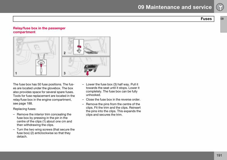
09 Maintenance and service
191
Fuses 09
Relay/fcompa
The fusees are loalso proTools forelay/fussee pag
Replacin
– Remofuse bcentrthen
– Turn fuse bdetac
use box in the passenger rtment
box has 50 fuse positions. The fus-cated under the glovebox. The box vides space for several spare fuses. r fuse replacement are located in the e box in the engine compartment,
e 188.
g fuses:
ve the interior trim concealing the ox by pressing in the pin in the
e of the clips (1) about one cm and withdrawing the clips.the two wing screws (that secure the ox) (2) anticlockwise so that they h.
– Lower the fuse box (3) half way. Pull it towards the seat until it stops. Lower it completely. The fuse box can be fully unhooked.
– Close the fuse box in the reverse order.– Remove the pins from the centre of the
clips. Fit the trim and the clips. Reinsert the pins into the clips. This expands the clips and secures the trim.

09
09 Maintenance and service
192
Fuse
37.Rese38.Rese39.Rese40.Rese41.Rese42.Rese43.Pho44.SRS45.Elec46.Pass47. Inter48.Was49.SRS
.................................................................. - additional heater for the passenger non (option) ....................................... 10 A
ol module (TCM), ABS system ............... 5 A............................................................ 10 Aule ECM (5-cyl.) .................................. 10 Adule, Keyless control module ............... 20 Ale ......................................................... 10 A (DLC), brake light switch .................... 15 Axiliary lamps relay coil ....................... 7.5 A
........................................................... 7.5 A’s side) ................................................ 15 Anger side) ........................................... 15 A
s
rve ...................................................................................-rve ...................................................................................-rve ...................................................................................-rve ...................................................................................-rve ...................................................................................-rve ...................................................................................-
ne, audio system, RTI (option) ..................................... 15 A system ....................................................................... 10 Atrical socket ................................................................ 15 Aenger compartment, glovebox and courtesy lighting ....5 Aior lighting ....................................................................5 Aher, rear window ......................................................... 15 A system ....................................................................... 10 A
50.Reserve ................51.Parking assistance,
compartment, Bi-Xe52.Transmission contr53.Power steering ......54.Engine control mod55.Remote control mo56.Siren control modu57.Data link connector58.Main beam right, au59.Main beam, left .....60.Seat heating (driver61.Seat heating (passe
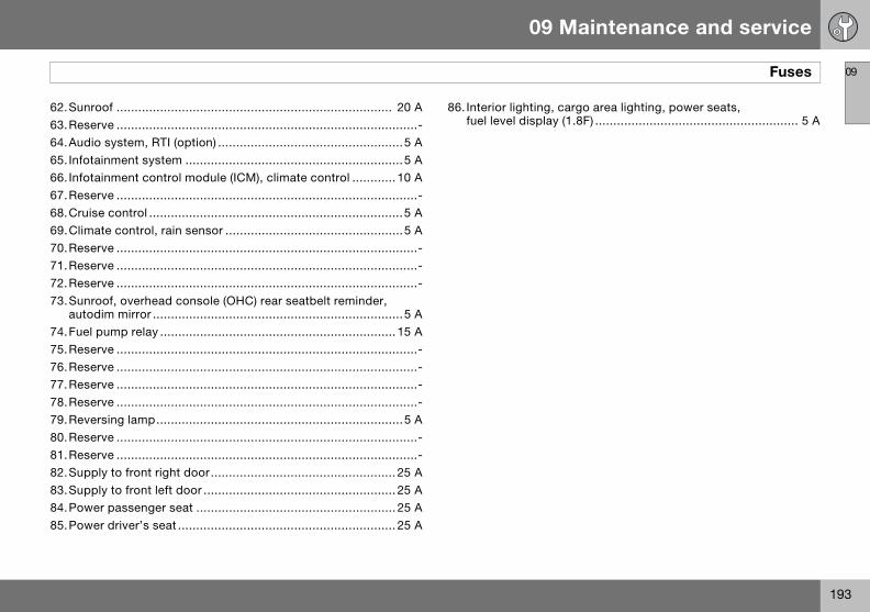
09
09 Maintenance and service
193
Fuses
62.Sun63.Rese64.Aud65. Infot66. Infot67.Rese68.Crui69.Clim70.Rese71.Rese72.Rese73.Sun
auto74.Fuel75.Rese76.Rese77.Rese78.Rese79.Reve80.Rese81.Rese82.Sup83.Sup84.Pow85.Pow
go area lighting, power seats, 8F) ........................................................ 5 A
roof ............................................................................ 20 Arve ...................................................................................-
io system, RTI (option) ...................................................5 Aainment system ............................................................5 Aainment control module (ICM), climate control ............ 10 Arve ...................................................................................-
se control ......................................................................5 Aate control, rain sensor .................................................5 Arve ...................................................................................-rve ...................................................................................-rve ...................................................................................-
roof, overhead console (OHC) rear seatbelt reminder, dim mirror .....................................................................5 A pump relay ................................................................. 15 Arve ...................................................................................-rve ...................................................................................-rve ...................................................................................-rve ...................................................................................-rsing lamp....................................................................5 Arve ...................................................................................-rve ...................................................................................-
ply to front right door................................................... 25 Aply to front left door ..................................................... 25 Aer passenger seat ....................................................... 25 Aer driver’s seat ............................................................ 25 A
86. Interior lighting, carfuel level display (1.

194
General ................................................................................................... 196Audio functions ...................................................................................... 197Radio functions ...................................................................................... 199CD functions ..........................................................................................203Menu structure – audio system ..............................................................205Phone functions (option) ........................................................................206Menu structure – phone ......................................................................... 213

10INFOTAINMENT SYSTEM

10 Infotainment system
196
Gene
10
Infotain
Infotainmaudio syment sythe contpad1, semessagfunction
Audio s
On/OffPOWERoff. If thenition ke
Dolby Surround Pro Logic II Dolby Surround Pro Logic II2 distributes the two stereo audio channels to left, centre, right and rear speakers. This provides a more realistic sound quality than that provided by standard two-channel stereo.
Dolby Surround Pro Logic II and the Dolby icon are trademarks of Dolby Laboratories Licensing Cor-
poration. The Dolby Surround Pro Logic II System is manufactured under license from Dolby Laboratories Licensing Corporation.
1 Option 2 Premium Sound
ral
ment system
ent is a system that integrates the stem and the phone1. The infotain-stem can be easily operated using rol panel or the steering wheel key-e page 54. The display (2) shows es and information on the current .
ystem
(1) switches the audio system on or audio system is active when the ig-y is turned to position 0 then it con-
tinues to be active until the key is removed from the ignition switch. The audio system is started automatically the next time the key is turned to position I.
Menus Some infotainment system functions are controlled via a menu system. The current menu level is shown at the top right of the display. Menu options are shown in the mid-dle of the display.
• MENU (4) leads to the menu system.• Up/down with the navigation button (5)
moves between menu options.• ENTER (7) selects or activates/deacti-
vates a menu option.• EXIT (6) leads back one step in the menu
structure. A long press on EXIT will exit the menu system.
ShortcutsMenu options are numbered and can also be selected directly with the keypad (3).
EquipmentThe audio system can be equipped with dif-ferent options and different versions. There are three audio system versions: Perform-ance, High Performance and Premium Sound. FM and AM radio with RDS and CD player is however included in each version.

10 Infotainment system
197
Audio functions
10
Audio c
1. VOL2. AM/3. MOD
CD/4. TUN5. SOU
VolumeUse VOpad to rdio voluon vehic
Sometimes the AUX external audio source can be heard at a different volume to the in-ternal audio sources, e.g. the CD player. If the audio volume of the external audio source is too high then the sound quality can be impaired. Prevent this by adjusting the in-put volume of the AUX input.
– Set the audio system in AUX mode using MODE.
– Press MENU and then ENTER.– Scroll to AUX input Volume and press
ENTER. – Turn TUNING or press right/left on the
navigation button.
Audio settings
Adjusting audio settings Repeatedly pressing SOUND browses be-tween the following alternatives. Adjust by turning TUNING.
• BASS – Bass level.• TREBLE – Treble level.• FADER – Balance between the front and
rear speakers.• BALANCE – Balance between the left and
right-hand speakers.
ontrols
UME – KnobFM – Audio source selectionE – Audio source selection,
AUXING – KnobND – Button
LUME (1) or the steering wheel key-egulate the volume, see page 54. Au-me adjusts automatically depending le speed, see page 198.
Audio source selectionRepeatedly pressing AM/FM switches be-tween FM1, FM2 and AM. Repeatedly press-ing MODE switches between CD and AUX.
AUX1
The AUX input can be used for connecting an MP3 player for example.
Input for external audio source (AUX) 3.5 mm
1 High Performance and Premium Sound.
NOTE
The audio quality may be impaired if the player is charged while the audio system is in AUX mode. In which case, avoid charging the player.
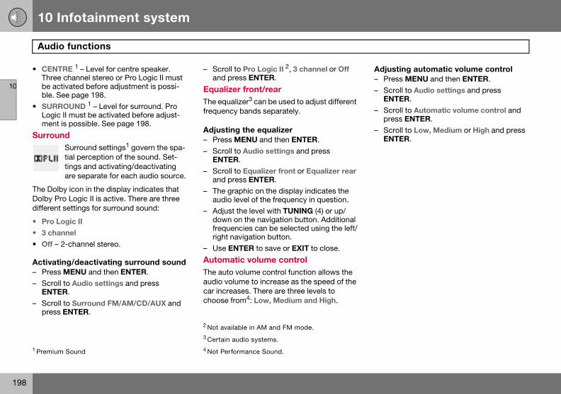
10 Infotainment system
198
Audi
10
• CENTThreebe acble. S
• SURRLogicment
Surrou
The DolDolby Pdifferent
• Pro L• 3 cha
• Off –
Activat– Press– Scrol
ENTE– Scrol
press
Adjusting automatic volume control– Press MENU and then ENTER.– Scroll to Audio settings and press
ENTER.– Scroll to Automatic volume control and
press ENTER.– Scroll to Low, Medium or High and press
ENTER.
1 Premium
o functions
RE 1 – Level for centre speaker. channel stereo or Pro Logic II must tivated before adjustment is possi-ee page 198.OUND 1 – Level for surround. Pro
II must be activated before adjust- is possible. See page 198.
nd Surround settings1 govern the spa-tial perception of the sound. Set-tings and activating/deactivating are separate for each audio source.
by icon in the display indicates that ro Logic II is active. There are three settings for surround sound:
ogic IInnel
2-channel stereo.
ing/deactivating surround sound MENU and then ENTER.l to Audio settings and press R.
l to Surround FM/AM/CD/AUX and ENTER.
– Scroll to Pro Logic II 2, 3 channel or Off and press ENTER.
Equalizer front/rear The equalizer3 can be used to adjust different frequency bands separately.
Adjusting the equalizer– Press MENU and then ENTER.– Scroll to Audio settings and press
ENTER.– Scroll to Equalizer front or Equalizer rear
and press ENTER.– The graphic on the display indicates the
audio level of the frequency in question.– Adjust the level with TUNING (4) or up/
down on the navigation button. Additional frequencies can be selected using the left/right navigation button.
– Use ENTER to save or EXIT to close.
Automatic volume control The auto volume control function allows the audio volume to increase as the speed of the car increases. There are three levels to choose from4: Low, Medium and High.
Sound
2 Not available in AM and FM mode.3 Certain audio systems.4 Not Performance Sound.

10 Infotainment system
199
Radio functions
10
Radio c
1. FM/2. Stat3. TUN4. SCA5. Nav6. EXIT7. AUT
Tuning
Automa– Selec– Give
navig
Automatic storage of stations AUTO (7) seeks out the ten strongest radio stations and stores them automatically in a separate memory. The function is especially useful in areas where the radio stations and their frequencies are unfamiliar.
Starting automatic storage of stations– Select wavelength using AM/FM (1).– Hold AUTO (7) depressed until Autostor-
ing... appears on the display.Once Autostoring... disappears from the dis-play, the stations are stored. The radio con-tinues in Auto mode and Auto appears on the display. The automatically stored presets can now be selected using the preset buttons (2).
Cancelling automatic storage of sta-tions– Press EXIT (6).Selecting an autostored presetAllowing the radio to remain in Auto mode provides access to the autostored presets.
– Briefly press AUTO (7).Auto appears on the display.
– Press a preset button (2).The radio remains in Auto mode until it is ex-ited by a brief press on AUTO (7), EXIT (6) or AM/FM (1).
ontrols
AM – Wavelength selectionion presetsING – Knob for station searchesN – Scanningigation button – Tuning and menus – Cancel current functionO – Automatic storage of stations
tic tuningt wavelength using AM/FM (1).a brief press, left or right, on the ation button (5).
Manual tuning– Select wavelength using AM/FM (1).– Adjust the frequency by turning
TUNING (3).Tune into a station with a long press (left or right) on the navigation button or by using the steering wheel keypad:
– Hold the right or left side of the navigation button depressed until the desired fre-quency appears on the display.
As long as the frequency graphic appears on the display, searching can be resumed by briefly pressing the navigation button (left or right) (5)
Storing stations Ten station presets can be stored per wave-length. FM has two memories for presets: FM1 and FM2. Preset stations are selected using the preset buttons (2) or the steering wheel keypad.
Storing stations manually– Tune into a station.– Hold a station preset button depressed
until the message Station stored appears on the display.

10 Infotainment system
200
Radi
10
StoringmemorAn autothe FM o
– BrieflAuto ap
– Press– Press
will bthe mthe d
The radstation c
ScanniSCAN (4wavelention is foapprox.sumed.
Activat– Selec– PressSCAN aSCAN o
StoringA desirewhile Sc
he programme functions alarm (ALARM), raffic information (TP), news (NEWS), and rogramme types (PTY) interrupt one anoth-r in order of priority, where alarm has the ighest priority and programme types has he lowest. For further programme interrup-ion settings, see EON and REG on age 202. The programme functions are odified via the menu system, see page 196.
eturning to the interrupted audio ourceress EXIT to return to the interrupted audio ource.
larm his function is used to warn of serious acci-ents and catastrophes. The alarm cannot e temporarily interrupted or deactivated. he message ALARM! appears on the dis-lay when an alarm message is transmitted.
raffic information – TP This function allows traffic informa-tion sent within a set station’s RDS network to break through. TP indi-cates that the function is activated.
f the set station can send traffic information hen appears on the display.
ctivating/deactivating TPPress MENU and then ENTER.
o functions
autostored presets in another ystored preset can be transferred to r AM memory.
y press AUTO (7).pears on the display.
a preset button. the button under which the station e stored and hold it depressed until essage Station stored appears on isplay.io exits Auto mode and the stored an be selected as a preset.
ng ) automatically searches through a gth for strong stations. When a sta-und, it is played for
eight seconds before scanning is re-
ing/deactivating Scant wavelength using AM/FM. SCAN to activate.ppears on the display. Close using r EXIT.
a stationd station can be stored as a preset an is active.
– Press a preset button and hold it de-pressed until the message Station stored appears on the display.
Scan is interrupted and the stored station can be selected as a preset.
RDS functionsRadio Data System – RDS links FM transmit-ters into a network. An FM transmitter in such a network sends information that gives an RDS radio the following functions:
• Automatically switches to a stronger transmitter if reception in the area is poor.
• Searches for programme form, such as traffic information or news.
• Receives text information on current radio programme.
Some radio stations do not use RDS or only some if its functionality.
Programme functions In FM mode, the radio can search for stations with certain programme types. If a required programme type is located the radio can switch stations interrupting the audio source currently in use. For example, if the CD player is in use, it is paused. The interrupting trans-mission is played at a preset audio volume, see page 202. The radio returns to the previ-ous audio source and audio volume when the set programme type is no longer broadcast.
Ttpehttpm
RsPs
ATdbTp
T
It
A–

10 Infotainment system
201
Radio functions
10
– ScrolTP fromThe radtion fromall statio
– Selec– Press– Scrol
press– Scrol– ScrolEither TTP fromplay.
– PressActivatTP searwhile anbeing plsearcheent RDS
– Press– Scrol
press– Scrol– Scrol
function allows programme types broadcast within a set station’s RDS network to break through.
Activating/deactivating PTY– Select FM1 or FM2 with FM/AM.– Press MENU and then ENTER.– Scroll to PTY and press ENTER.– Scroll to Select PTY and press ENTER.A list of programme types appears: Current affairs, Information etc. The PTY function is activated by selecting programme types and deactivated by clearing all PTYs.
– Select the desired programme types or Clear all PTY
Search PTYThis function searches the entire wavelength for the selected programme type.
– Activate PTY.– Press MENU and then ENTER.– Scroll to PTY and press ENTER.– Scroll to Search PTY and press ENTER.If the radio finds any of the selected pro-gramme types then the display shows >| To seek . Press the navigation button to the right to continue searching for another broadcast of the selected programme types.
l to TP and press ENTER. current station/all stations
io can interrupt with traffic informa- only the set (current) station or from ns.
t an FM station. MENU and then ENTER.l to Advanced radio settings and ENTER.l to TP and press ENTER.l to TP Station and press ENTER.P from current station or all stations will appear on the dis-
ENTER.ing/deactivating TP searchch is useful during long journeys audio source other than the radio is ayed. The function automatically s for traffic information within differ- networks.
MENU and then ENTER.l to Advanced radio settings and ENTER.l to TP and press ENTER.l to TP search and press ENTER.
News This function allows news broad-casts within a set station’s RDS network to break through. The mes-sage NEWS indicates that the func-
tion is active.
Activating/deactivating News– Press MENU and then ENTER.– Scroll to News and press ENTER.News from current station/all stations The radio can interrupt with news from only the set (current) station or from all stations.
– Select an FM station.– Press MENU and then ENTER.– Scroll to Advanced radio settings and
press ENTER.– Scroll to News station and press ENTER.Either News from current station or News from all stations will appear on the display.
– Press ENTER.
Programme types – PTY The PTY function can be used to select different programme types, such as pop music and serious classic. The PTY symbol
indicates that the function is active. This

10 Infotainment system
202
Radi
10
DisplayThe procan be s
Activat– Press– Scrol– Scrol
Radio tSome Rprogrammation c
Activat– Press– Scrol
AutomThe AF transmitsometimFM wavthis occExit to c
• Distant 1 – interrupts if the station trans-mitter is far away, even if there is a lot of static.
• Off – no interruption for programmes from other transmitters.
Activating/deactivating EON– Press MENU and then ENTER.– Scroll to Advanced radio settings and
press ENTER.– Scroll to EON and press ENTER.– Scroll to Local, Distant or Off and press
ENTER.
Resetting RDS functions Resets all radio settings to the original facto-ry settings.
– Press MENU and then ENTER.– Scroll to Advanced radio settings and
press ENTER.– Scroll to Reset all and press ENTER.
Volume control, programme types The interrupting programme types are heard at the volume selected for each programme type. If the volume level is adjusted during the programme interruption, the new level is saved until the next programme interruption.
NO
Not all
1 Default/Factory setting.
o functions
of programme typegramme type of the current station hown on the display.
ing/deactivating display MENU and then ENTER.l to PTY and press ENTER.l to Show PTY and press ENTER.
ext DS stations transmit information on me content, artists, etc. This infor-an be shown on the display.
ing/deactivating radio text MENU and then ENTER.l to Radio text and press ENTER.
atic frequency update – AF function selects one of the strongest ters for a set station. The radio may es need to search through the entire
elength to find a strong transmitter. If urs, the radio mutes and PI Seek ancel appears on the display.
Activating/deactivating AF– Press MENU and then ENTER.– Scroll to Advanced radio settings and
press ENTER.– Scroll to AF and press ENTER.
Regional radio programmes – REG This function causes the radio to continue with a regional transmitter even if its signal strength is low. REG indicates that the function is
active. The regional function is normally de-activated.
Activating/deactivating REG– Press MENU and then ENTER.– Scroll to Advanced radio settings and
press ENTER.– Scroll to Regional and press ENTER.
Enhanced Other Networks – EON The EON function is especially useful in ur-ban areas with many regional radio stations. It allows the distance between the car and the radio station transmitter to determine when programme functions should interrupt the current audio source.
• Local – interrupts only if the radio station transmitter is close.
TE
radio stations support this function.

10 Infotainment system
203
CD functions
10
CD fun
1. Navitrack
2. CD c3. CD i4. CD i5. MOD
and 6. TUN
StartinIf a mussystem
PauseIf the volume is turned down completely, the CD player is stopped. The player is restarted when volume is increased.
Audio files2
The CD player also supports MP3 and WMA format audio files.
When a CD containing audio files is inserted into the player the disc’s directory structure is read in. It may take a while before playback starts due to the quality of the disc.
Navigation and playbackIf a disc containing audio files is inside the CD player then ENTER leads to the disc’s di-rectory structure. The directory structure is navigated in the same way as the audio sys-tem’s menu structure. Audio files have the symbol and directories have the symbol . Start audio file playback with ENTER.
When the playback of a file is finished the playback of the other files in the same direc-tory continues. Directory change takes place
1 Option2 High Pe
NOTE
Certain types of copy-protected audio files cannot be read by the player.
ction controls
gation button – Fast forward/rewind, selection and menushanger position selection1
nsertion/ejectnsertion/eject slotE – Audio source selection CD
AUX2
ING – Knob for track selection
g playback (CD player)ic CD is in the player when the audio is in CD mode then playback is start-
ed automatically. Otherwise, load a disc and change to CD mode by pressing MODE.
Starting playback (CD changer)If a CD position with a music CD is already selected when the audio system is activated then playback starts automatically. Other-wise change to CD changer mode using MODE and select a disc with the number buttons 1–6 or Up/Down on the navigation button.
Inserting a CD (CD changer)– Select an empty position with buttons 1–6
or Up/Down on the navigation button.An empty position is marked on the display. The text Insert disc shows that a new disc can be inserted. The CD changer can hold up to six CDs.
– Insert a CD in the slot of the CD changer.CD ejectA CD will stay in the ejected position for ap-prox. 12 seconds. Following which it is re-in-serted in the player and playback continues.
Eject individual discs by pressing the eject button (3).
Eject all discs with a long press on the eject button. The entire magazine is emptied disc by disc. The message Eject all is shown in the display.rformance and Premium Sound

10 Infotainment system
204
CD fu
10
automatrectory
Press ledisplay iaudio fil
Fast-wfiles Short prbutton aaudio filwind CDsteeringthis purp
Scan CThis funeach CDtivate. Intinue pldio file.
RandomThis funder. Thescrolled
If a CD with audio files is being played:
– Press MENU and then ENTER.– Scroll to Random and press ENTER.– Scroll to Single disc or Folder and press
ENTER.The function is deactivated when another CD is selected.
Disc text If title information is stored on a music CD it can be shown on the display1.
Activating/deactivating– Start CD playback.– Press MENU and then ENTER.– Scroll to Disc text and press ENTER.
CDsUsing low quality CD discs could result in poor or non-existent sound.
NO
It is onCD tra 1 Only applies to CD changer.
IMPORTANT
Use only standard discs (12 cm in diame-ter). Do not use CDs with adhesive disc la-bels. The heat in the CD player may cause the label to come off, damaging the CD player.
nctions
ically when all files in the current di-have been played back.
ft/right on the navigation button if the s not wide enough to show the whole e name.
ind/change CD tracks and audio
esses right/left on the navigation re used to scroll between CD tracks/es. Long presses are used to fast- tracks/audio files. TUNING (or the wheel keypad) can also be used for ose.
D ction plays the first ten seconds of track/audio file. Press SCAN to ac-terrupt with EXIT or SCAN to con-
ayback of the current CD track/au-
ction plays the tracks in random or- random CD tracks/audio files can be through in the normal way.
Different messages appear on the display depending on which random function has been selected.
• RANDOM means that the tracks from only one music CD are played
• RND ALL means that all tracks on all music CDs in the CD changer are played.
• RANDOM FOLDER means that the audio files in a directory on the current CD are played.
Activating/deactivating (CD player)– If a normal music CD is being played:– Press MENU and then ENTER.– Scroll to Random and press ENTER.If a disc with audio files is being played:
– Press MENU and then ENTER.– Scroll to Random and press ENTER.– Scroll to Folder or Disc and press ENTER.Activating/deactivating (CD changer)If a normal music CD is being played:
– Press MENU and then ENTER.– Scroll to Random and press ENTER.– Scroll to Single disc or All discs and press
ENTER.The option All discs only applies to the mu-sic CDs in the changer.
TE
ly possible to scroll between random cks on the current disc.

10 Infotainment system
205
Menu structure – audio system
10
FM me1. New
2. TP3. PTY
4. Rad5. Adva
6. Aud
AM me1. Aud
CD me1. Ran
2. New
3. TP4. Disc
5. Aud
CD cha1. Ran2. New
3. TP4. Disc
5. Aud
AUX m1. AUX1 Certain
nu s
io textnced radio settings
io settings1
nuio settings1
nudom
s
text
io settings1
nger menudom s
text
io settings1
enu volume
2. News
3. TP4. Audio settings1
audio systems.
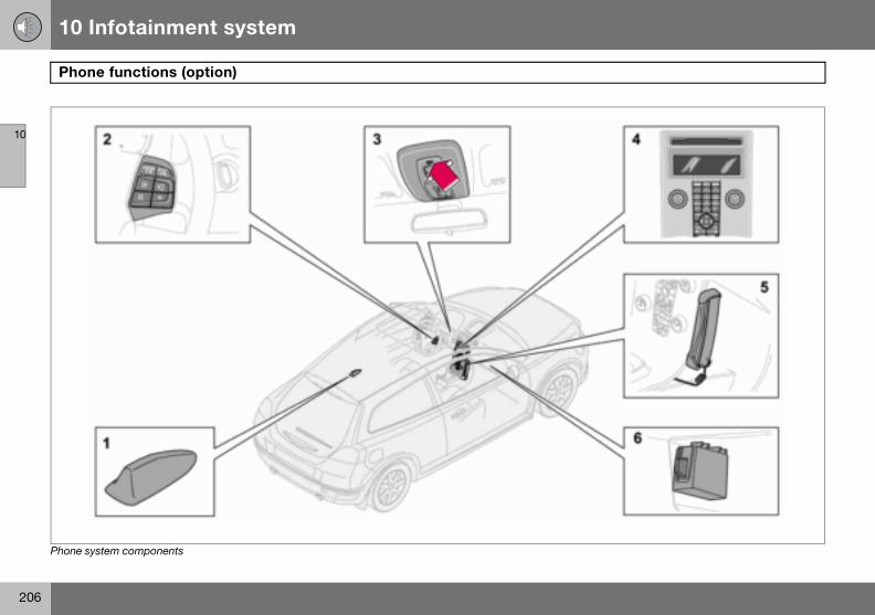
10 Infotainment system
206
Phon
10
Phone sy
e functions (option)
stem components

10 Infotainment system
207
Phone functions (option)
10
Phone
1. Ante
2. SteeMost phcessed
3. MicrThe hanthe roof
4. CentAll phonbe regu
5. Privamarket
6. SIM
Genera• Alwa• If the
hand• The p
when• Switc
SIM card
The phone can only be used with a valid SIM card (Subscriber Identity Module). The card is available from various network operators. Contact your network operator if you experi-ence difficulties with the SIM card.
Double SIM cardsMany network operators offer two SIM cards for the same phone number. The extra SIM card can be used in the car.
Inserting the SIM card– Switch off the phone and open the glove-
box.
system components
nna
ring wheel keypadone system functions can be ac-via the keypad. See page 208.
ophonedsfree microphone is integrated in console beside the rearview mirror.
re console control panele functions (except call volume) can lated via the control panel.
cy handset (option certain s)
card reader
lys put traffic safety first. driver needs to use the privacy set, park the car in a safe place first.hone system must be switched off the car is refuelled.h off the system near blasting work.
• Only entrust phone system servicing to an authorised Volvo workshop.
Emergency calls Emergency calls to alarm centres can be made without a SIM card as long as there is coverage by a GSM operator.
Making an emergency call– Activate the phone.– Ring the emergency number that applies
to your region (within EU: 112).– Press ENTER.
IDIS (Intelligent Driver Information System) The IDIS system allows incoming phone calls and text (SMS) messages to be delayed so that the driver can concentrate on driving. Incom-ing calls and text messages can be delayed five seconds before they are connected. Missed calls are shown on the display. IDIS can be deactivated using menu function 5.6.2. See page 214.

10 Infotainment system
208
Phon
10
– Pull ocard
– Positthe medgebeve
– Caref
MenusPage 19function
Traffic For safesystem cess of menu sylimiter ction 5.6.
Steering wheel keypad
When the phone is active, the steering wheel keypad is locked to phone functions. To con-trol the audio system, the phone must be in standby mode.
1. ENTER – Works the same as on the control panel.
2. EXIT – Works the same as on the control panel
3. Call volume – Increase/decrease4. Navigation buttons – Scroll in menus
e functions (option)
ut the SIM card holder (1) in the SIM reader.ion the SIM card in the holder with etal surface visible. The bevelled of the SIM card should align with the l of the SIM card holder.ully press in the SIM card holder.
6 describes how to control phone s with the menu system.
safetyty reasons, parts of the phone menu cannot be accessed at speeds in ex-8 km/h. Only activities started in the stem can be completed. The speed an be deactivated using menu func-1 Menu lock, see page 213.
Phone controls
Centre console control panel
1. VOLUME – Control the background vol-ume from the radio, for example, during a call.
2. Number and letter buttons3. MENU – Opens the main menu4. EXIT – End/refuse calls, clear entered
characters5. Navigation button – Scroll in menus
and character rows6. ENTER – Accept calls, activate the
phone from standby mode7. PHONE – On/off and standby mode

10 Infotainment system
209
Phone functions (option)
10
On/Off
A handsphone sthe ignitthe phonphone anext tim
ActivatPhone swhen th
– Press– Enter
press
DeactivNo callsdeactiva
– Hold activa
StandbIn standuse whinot possmode.
PuttingThe phofore it ca
Call waitingA two-tone signal during a phone call indi-cates that there is another incoming call. An-swer? appears on the display. The call can be refused or taken in the normal manner. If the incoming call is taken, the previous call is put on hold.
Putting a call on hold/resuming a call– Press MENU.– Scroll to Hold or Hold off and press
ENTER.
Dialling a third party– Put the call on hold.– Dial the number of the third party.
Switching between calls– Press MENU.– Scroll to Swap and press ENTER.
Starting a conference callA conference call consists of at least three parties that can talk to one another. Once a conference call has been initiated, no more parties can be connected. All calls are ended when a conference call is ended.
– Start two phone calls– Press MENU.– Scroll to Join and press ENTER.
et appears in the display when the ystem is active or in standby mode. If ion key is turned to position 0 when e is in one of these modes, the
utomatically resumes this mode the e the key is turned to position I or II.
ing the phone systemystem functions can only be used e phone is in active mode.
PHONE. the PIN code (if necessary) and ENTER.
ating the phone system can be received when the phone is ted.
PHONE depressed until the phone is ted.
yby mode, the audio system can be in le calls are received. However, it is ible to make calls when in standby
the phone in standby mode ne must first be in active mode be-n be put in standby mode.
– Press PHONE or EXIT.Activating from standby mode– Press PHONE.
Making and receiving calls If the privacy handset is raised when a phone call is started, the sound will come from the handsfree system. For information on switch-ing between privacy handset and handsfree during a call, see page 211.
To call– Activate the phone system (if necessary).– Dial the number or use the phone book,
see page 211.– Press ENTER or lift the handset. Release
the handset by pressing it down.
Receiving a callFor Auto answer, see menu option 4.3, page 213.
– Press ENTER or lift the handset. Release the handset by pressing it down.
Ending a call– Press EXIT or hang up the handset.
Refusing a call– Press EXIT.

10 Infotainment system
210
Phon
10
VolumeThe phospeaker
Call vo
the hand
Audio sAudio syduring athe prevume is rel is retacan alsophone cfunctiongrated p
EnterinText is e
– Presster - o
Handling numbers
Calling the last number dialledThe phone automatically stores the last phone numbers dialled.
– Press ENTER.– Scroll to a number and press ENTER.
Phone bookIf the phone book contains a live caller’s con-tact information then this is shown in the dis-play. Contact information can be stored on the SIM card and in the phone.
Storing contacts in the phone book– Press MENU.– Scroll to Phone book and press ENTER.– Scroll to New number and press ENTER.– Enter a name and press ENTER.– Enter a number and press ENTER.– Scroll to SIM card or Phone and press
ENTER.Searching for contacts in the phone bookUse the down arrow of the navigation button instead of MENU for direct access to the Search menu.
– Press MENU.– Scroll to Phone book and press ENTER.
1 Premium
e functions (option)
ne uses the driver’s door or centre 1.
lume Call volume is regulated with the buttons of the steering wheel keypad.
If the privacy handset is used, volume is regulated with a wheel on the side of
set.
ystem volumestem volume is temporarily lowered phone call. Once the call is ended ious volume is resumed. If the vol-egulated during the call, the new lev-ined once the call is ended. Sound be automatically muted during a all, see menu 5.5.3, page 214. This is only available with the Volvo inte-hone system.
g text ntered using the phone keypad.
the button with the desired charac-nce for the first character on the
button, twice for the second, etc. See table.
– Press 1 for a space. If two characters in a row are to be entered using the same button, press * or wait a few seconds.
A short press on EXIT deletes an input char-acter. A long press on EXIT will clear all en-tered characters.
Sound.
1 space 1- ? ! , . : " ' ( )2 a b c 2 ä å à æ ç3 d e f 3 è é4 g h i 4 ì5 j k l 56 m n o 6 ñ ö ò Ø7 p q r s 7 ß8 t u v 8 ü ù9 w x y z 9* Used if two characters are to be
ended with the same button.0 + 0 @ * # & $ £ / %# Switch between upper and lower
case.

10 Infotainment system
211
Phone functions (option)
10
– Scrol– Enter
press– ScrolCopyinand Ph– Press– Scrol– Scrol– Scrol
and pDeletin– Press– Scrol– Scrol– Enter
press– Scrol
ENTE– ScrolErase a– Press– Scrol– Scrol
pressIf requirset defa
Calling from the phone book – Press MENU.– Scroll to Phone book and press ENTER.All contacts in the phone book memory are displayed. The number of contacts displayed can be reduced by entering part of the con-tact’s name.
– Scroll to a contact and press ENTER.
Functions during a call Several functions are available during a call. Some functions can only be used when a call is on hold.
Press MENU to access the In-call menu and scroll to one of the following alternatives:
• Mute/Mute off – Mute mode.• Hold/Hold off – Put a call on hold or
resume a call.• Handsfree/Handset – Use handsfree or
the privacy handset.• Phone book – Access the phone book.• Join – Conference calling (available if
more than three parties are connected)
NOTE
Press ENTER to dial.
l to Search and press ENTER. the first few letters of the item and ENTER, or simply press ENTER.l to an item and press ENTER.g entries between the SIM card one book MENU.l to Phone book and press ENTER.l to Copy all and press ENTER.l to SIM to phone or Phone to SIM ress ENTER.g contacts from the phone book MENU.l to Phone book and press ENTER.l to Search and press ENTER. the first few letters of the item and ENTER, or simply press ENTER.l to the item to be erased and press R.
l to Erase and press ENTER.ll contacts MENU.l to Phone book and press ENTER.l to Erase SIM or Erase phone and ENTER.
ed, enter phone code. The factory-ult code is 1234.
Speed dial A keypad button (1- 9) can be used as a speed dial number for a contact in the phone book.
– Press MENU.– Scroll to Phone book and press ENTER.– Scroll to One-key dial and press ENTER.– Scroll to Select numbers and press
ENTER.– Scroll to the digit of the keypad button for
the speed dial number and press ENTER.– Enter the first few letters of the item and
press ENTER, or simply press ENTER.– Scroll to an item and press ENTER.– Hold EXIT depressed to leave the menu
system.Calling using speed dial– Hold the desired keypad button for
approx. two seconds or briefly press the button and then ENTER.
To use the speed dial function One-key dial must be activated in the Phone book menu, see page 215.
NOTE
When the phone is switched on, it takes a while before speed dialling is available.

10 Infotainment system
212
Phon
10
• Swapble if
SMS –
Readin– Press– Scrol– Scrol– ScrolThe mesAdditioning ENTthe men
Writing– Press– Scrol– Scrol– Enter– Scrol– Enter
IMEI nuIn orderer must numberis progrshow thdown an
e functions (option)
– Switch between two calls (availa-up to three parties are connected).
Short Message Service
g SMS MENU.l to Messages and press ENTER.l to Read and press ENTER.l to a message and press ENTER.sage text is shown in the display. al selections can be made by press-ER. Hold EXIT depressed to leave u system.
and sending MENU.l to Messages and press ENTER.l to Write new and press ENTER. text and press ENTER.l to Send and press ENTER. a phone number and press ENTER.
mber to block a phone the network provid-be advised of the phone’s IMEI . This is a 15 digit serial number that ammed in the phone. Dial *#06# to is number in the display. Write it d keep it in a safe place.
Specifications
Output 2 WSIM card SmallMemory entries 2551
1The capacity of the SIM card’s memory varies depending on the subscription.
SMS (Short Message Service)
Yes
Data/Fax NoDualband (900/1800 MHz) Yes
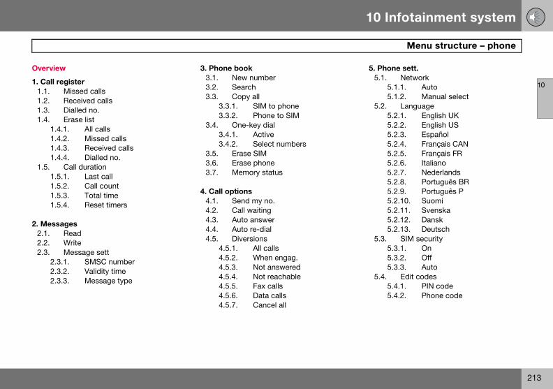
10 Infotainment system
213
Menu structure – phone
10
Overvie
1. Call r1.1.1.2.1.3.1.4.
1.41.41.41.4
1.5.1.51.51.51.5
2. Mess2.1.2.2.2.3.
2.32.32.3
5. Phone sett.5.1. Network
5.1.1. Auto5.1.2. Manual select
5.2. Language5.2.1. English UK5.2.2. English US5.2.3. Español5.2.4. Français CAN5.2.5. Français FR5.2.6. Italiano5.2.7. Nederlands5.2.8. Português BR5.2.9. Português P5.2.10. Suomi5.2.11. Svenska5.2.12. Dansk5.2.13. Deutsch
5.3. SIM security5.3.1. On5.3.2. Off5.3.3. Auto
5.4. Edit codes5.4.1. PIN code5.4.2. Phone code
w
egisterMissed callsReceived callsDialled no.Erase list
.1. All calls
.2. Missed calls
.3. Received calls
.4. Dialled no.Call duration
.1. Last call
.2. Call count
.3. Total time
.4. Reset timers
agesReadWriteMessage sett
.1. SMSC number
.2. Validity time
.3. Message type
3. Phone book3.1. New number3.2. Search3.3. Copy all
3.3.1. SIM to phone3.3.2. Phone to SIM
3.4. One-key dial3.4.1. Active3.4.2. Select numbers
3.5. Erase SIM3.6. Erase phone3.7. Memory status
4. Call options4.1. Send my no.4.2. Call waiting4.3. Auto answer4.4. Auto re-dial4.5. Diversions
4.5.1. All calls4.5.2. When engag.4.5.3. Not answered4.5.4. Not reachable4.5.5. Fax calls4.5.6. Data calls4.5.7. Cancel all

10 Infotainment system
214
Menu
10
5.5.5.55.55.55.5
5.6.5.65.6
5.7.
2. Messages2.1. ReadReceived text messages. Select whether to erase, forward, change or save the entire message or parts of it.
2.2. WriteWrite a message using the keypad. Choose whether to save or send it.
2.3. Message settEnter the number (SMSC number) of the message centre to which messages are to be transferred as well as how long they are to be saved at the message centre. Contact your network operator for information on message settings. Normally, these settings should not be altered.
2.3.1. SMSC number2.3.2. Validity time2.3.3. Message type
3. Phone book3.1. New numberStore names and phone numbers in the phone book, see page 210.
3.2. SearchSearch for a name in the phone book.
structure – phone
Sounds.1. Ring volume.2. Ring signal.3. Mute radio.4. Msg. beepTraff. safety
.1. Menu lock
.2. IDISFactory sett.
Description of menu options
1. Call register1.1. Missed callsList of missed calls. You can choose to call, erase or store the number in the phone book.
1.2. Received callsList of received calls. You can choose to call, erase or store the number in the phone book.
1.3. Dialled no.List of dialled numbers. You can choose to call, erase or store the number in the phone book.
1.4. Erase listErase the lists found in the menus 1.1, 1.2 and 1.3 as below.
1.4.1. All1.4.2. Missed1.4.3. Received1.4.4. Dialled no.
1.5. Call durationDuration of all calls or of the most recent call. The phone code is required to reset the call timer (see menu 5.4).
1.5.1. Last call1.5.2. Call count1.5.3. Total time1.5.4. Reset timers

10 Infotainment system
215
Menu structure – phone
10
3.3. CoCopy phSIM car
3.3.1.3.3.2.
3.4. OnA numbstored a
3.5. EraErase th
3.6. EraErase th
3.7. MeShows hthe SIMshows htions are
4. Call 4.1. SeDisplaysthe persoperato
4.2. CaBe alertanother
5.2.3. Español5.2.4. Français CAN5.2.5. Français FR5.2.6. Italiano5.2.7. Nederlands5.2.8. Português BR5.2.9. Português P5.2.10. Suomi5.2.11. Svenska5.2.12. Dansk5.2.13. Deutsch
5.3. SIM securitySelect if the PIN code should be on, off or if the phone should automatically give the PIN code.
5.3.1. On5.3.2. Off5.3.3. Auto
5.4. Edit codesChange PIN or phone code. Write the codes down and keep them in a safe place.
5.4.1. PIN code5.4.2. Phone code. The factory-set phone
code 1234 is used until you change to your own code. The phone code is used to reset the call timer.
5.5. Sounds5.5.1. Volume. Adjust the ring tone
volume.
py allone numbers and names from the
d to the phone memory.
From SIM to phone memoryFrom phone to SIM memory
e-key dialer stored in the phone book can be s a speed dial number.
se SIMe entire SIM card memory.
se phonee entire phone memory.
mory statusow many positions are occupied in
card and phone memory. The table ow many of the total number of posi- occupied, e.g. 100 (250).
optionsnd my no. or hides your phone number to/from on you call. Contact your network r regarding ex-directory numbers.
ll waitinged during a phone call that there is incoming call.
4.3. Auto answerAutomatically answers incoming calls.
4.4. Auto re-dialCalls a previously engaged number.
4.5. DiversionsChoose when and what type of calls are to be diverted to a specified phone number.
4.5.1. All calls (this setting only applies during the call in progress).
4.5.2. When engag.4.5.3. Not answered4.5.4. Not reachable4.5.5. Fax calls4.5.6. Data calls4.5.7. Cancel all
5. Phone settings5.1. NetworkChoose a network automatically or manually. The selected network is shown in the display in the phone’s basic mode.
5.1.1. Auto5.1.2. Manual select
5.2. LanguageSelect the phone language.
5.2.1. English UK5.2.2. English US
10 Infotainment system
216
10
5.5.2.
5.5.3.5.5.4.
5.6. Tra5.6.1.
5.6.2.
5.7. FaReset th
Ring signal. There are seven different ring tones.Mute radio. On/OffMsg. beep
ffic safetyMenu lock. Deactivating the menu lock allows access to the entire menu while driving.IDIS. If the IDIS function is deacti-vated, incoming calls are not delayed, regardless of the driving situation.
ctory sett.e system’s factory settings.

10 Infotainment system
217
10
218
Type designation ....................................................................................220Dimensions and weights ........................................................................221Engine specifications .............................................................................224Engine oil ................................................................................................226Fluids and lubricants ..............................................................................230Fuel .........................................................................................................232Catalytic converter .................................................................................234Electrical system ....................................................................................235

11SPECIFICATIONS

11 Specifications
220
Type
11
wing the car’s type designation, vehicle tification and engine numbers can facili-all contact with a Volvo dealer regarding ar and when ordering spare parts and ssories.
ype designation, vehicle identification umber, maximum permissible weights, odes for colour and upholstery and type pproval number.ecal for parking heater.ngine type designation, component nd serial number.IN number (type and model year des-
gnation plus chassis number).ecal for engine oil.earbox type designation and serial umber:a) manual gearbox
b), (c) automatic gearbox
designation
Knoidentate the cacce
1. Tnca
2. D3. E
a4. V
i5. D6. G
n(
(

11 Specifications
221
Dimensions and weights
11
Dimens
Posiillus
G01559
ions
tion in tration
Dimensions cm
A Wheelbase 264B Length 425C Load length, floor, folded
seat149
D Load length, floor 66E Height 145F Front track 155G Rear track 154H Width 178I Width including door
mirrors204
3

11 Specifications
222
Dime
11
Weight
Kerb we90 % fugers andball loadload carthe paylkerb wedriver) =
Only for China
1. Gross vehicle weight2. Maximum trailer weightMaximum load: See registration document.
W
The capendinthe loa
nsions and weights
s
ight includes the driver, the fuel tank ll and all fluids. The weight of passen- accessories, such as a towbar, tow- (when a trailer is hitched, see table), riers, and space box etc. influences oad and must not be included in the ight. Permitted weight (in addition to Gross vehicle weight – Kerb weight.
See decal location on page 220.
1. Gross vehicle weight2. Max. train weight (car+trailer)3. Max. front axle load4. Max. rear axle load
ARNING
r’s driving characteristics change de-g on how heavily it is loaded and how d is distributed.

11 Specifications
223
Dimensions and weights
11
Max. ro
1.61.6D1.81.8F2.0others
Maximtrailer
700
of load: 75 kg
Maximum braked trailer weight kg
Maximum towball load kg
1200 7513001300130013501500
um unbraked weight kg
Maximum towball load kg
50

11 Specifications
224
Engin
11
Engine tserial nusee pag
2.4i T5
Engine B5244S4 B5254T3Output 125/6000 162/5000(hp/rpm 170/6000 220/5000Torque 230/4400 320/1500–4800No. of c 5 5Bore (m 83 83Stroke 90 93.2Swept 2.44 2.52Compr 10.3:1 9.0:1
e specifications
ype designation, component and mber can be read on the engine, e 220.
1.6 1.8 1.8F 2.0
designation B4164S3 B4184S11 B4184S8 B4204S3 (kW/rpm) 74/6000 92/6000 92/6000 107/6000) 100/6000 125/6000 125/6000 145/6000
(Nm/rpm) 150/4000 165/4000 165/4000 185/4500ylinders 4 4 4 4m) 79 83 83 87
(mm) 81.4 83.1 83.1 83volume (litres) 1.60 1.80 1.80 1.99ession ratio 11.0:1 10.8:1 10.8:1 10.8:1
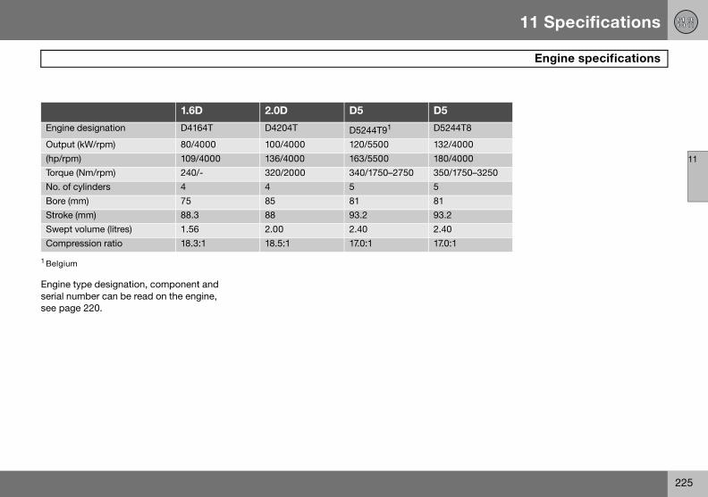
11 Specifications
225
Engine specifications
11
Engine tserial nusee pag
Engine 8
Output 0(hp/rpm 0Torque 0–3250No. of cBore (mStroke Swept Compr
1 Belgium
ype designation, component and mber can be read on the engine, e 220.
1.6D 2.0D D5 D5
designation D4164T D4204T D5244T91 D5244T
(kW/rpm) 80/4000 100/4000 120/5500 132/400) 109/4000 136/4000 163/5500 180/400
(Nm/rpm) 240/- 320/2000 340/1750–2750 350/175ylinders 4 4 5 5m) 75 85 81 81
(mm) 88.3 88 93.2 93.2volume (litres) 1.56 2.00 2.40 2.40ession ratio 18.3:1 18.5:1 17.0:1 17.0:1

11 Specifications
226
Engin
11
Advers
Check tjourneys
• towin• in mo• at hig
–30 �Also cheis often 10 km) w(below+
This canature or
Volvo re
Viscosity chart
e oil
e driving conditions
he oil level more frequently for long :
g a caravan or traileruntainous regionsh speedsin temperatures colder than C or hotter than +40 �C.ck the oil level more often if the car
driven short distances (less than hen temperatures are low
5 �C).
produce abnormally high oil temper- oil consumption.
commends oil products.
IMPORTANT
In order to fulfil the requirements for the en-gine’s service intervals all engines are filled with a specially adapted synthetic engine oil at the factory. The choice of oil has been made very carefully with regard to service life, starting characteristics, fuel consump-tion and environmental impact. An ap-proved engine oil must be used in order that the recommended service intervals can be applied. Only use a prescribed grade of oil (see the engine compartment decal) for both filling and oil change, otherwise you will risk affecting service life, starting char-acteristics, fuel consumption and environ-mental impact. Volvo Car Corporation disclaims all warranty liability if engine oil of the prescribed grade and viscosity is not used.

11 Specifications
227
Engine oil
11
Oil dec
Engin
2.4iT5
1 Includin
al The following applies when this adjacent oil decal is fitted in the car’s engine compart-ment. See location on page 220.
Oil grade: ACEA A3/B3/B4
Viscosity: SAE 0W–30
When driving under adverse conditions, use ACEA A5/B5 SAE 0W-30.
e variantFilling volume
between MIN–MAX (litres)
Volume1
(litres)
B5244S4 1.3 5.8B5254T3
g filter change.
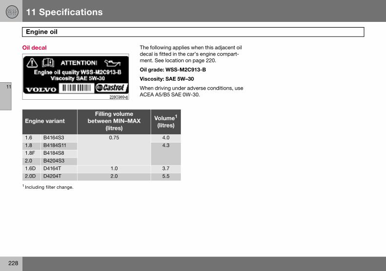
11 Specifications
228
Engin
11
Oil dec
Engin
1.61.81.8F2.01.6D2.0D
1 Includin
e oil
al The following applies when this adjacent oil decal is fitted in the car’s engine compart-ment. See location on page 220.
Oil grade: WSS-M2C913-B
Viscosity: SAE 5W–30
When driving under adverse conditions, use ACEA A5/B5 SAE 0W-30.
e variantFilling volume
between MIN–MAX (litres)
Volume1
(litres)
B4164S3 0.75 4.0B4184S11 4.3B4184S8B4204S3D4164T 1.0 3.7D4204T 2.0 5.5
g filter change.

11 Specifications
229
Engine oil
11
Oil dec
Engin
D5D5
1 Includin2 Belgium
NO
Under box oilserviceunder page 2
al The following applies when this adjacent oil decal is fitted in the car’s engine compart-ment. See location on page 220.
Oil grade: ACEA A5/B5
Viscosity: SAE 0W–30
e variantFilling volume
between MIN–MAX (litres)
Volume1
(litres)
D5244T8 1.5 6
D5244T92
g filter change
TE
normal driving conditions the gear- does not need changing during its life. However, it may be necessary
adverse driving conditions, see 26.

11 Specifications
230
Fluid
11
Fluid ecommended oil grade
Gearbo ansmission fluid: WSD-M2C200-C
ansmission fluid: WSS-M2C200-C3ansmission fluid: WSD-M2C200-Cansmission fluid: JWS 3309ansmission fluid: JWS 3309ansmission fluid: MTF 97309-10ansmission fluid: JWS 3309ansmission fluid: MTF 97309-10ansmission fluid: JWS 3309
Coolan oolant with corrosion inhibitor mixed with ater, see packaging. The thermostat starts ening at: ºC in petrol engines, and at 82 ºC in diesel gines.trol engine (1.6) 82 ºC
esel engine (1.6D) 83 ºC
s and lubricants
System Volume R
x oil 1.6 Manual 5-speed 2.1 litres Tr1.8 Manual 5-speed 1.9 litres1.6D Manual 5-speed 1.9 litres1.8F Manual 5-speed 1.9 litres2.0 Manual 5-speed 1.9 litres2.0D Manual 5-speed 2.2 litres Tr2.0D Manual 6-speed 1.7 litres Tr2.4D Automatic gearbox 7.75 litres TrD5 Automatic gearbox 7.75 litres Tr2.4i Manual 5-speed 2.1 litres Tr2.4i Automatic gearbox 7.75 litres TrT5 Manual 6-speed 2.0 litres TrT5 Automatic gearbox 7.75 litres Tr
t 5-cyl. Petrol, manual gearbox 9.5 litres Cwop90enpedi
5-cyl. Petrol, automatic gearbox 10.0 litres5-cyl. Diesel (D5) 11.0 litres4-cyl. Petrol (1.8, 1.8F and 2.0) 7.5 litres4-cyl. Diesel (2.0D) 9.5 litres4-cyl. Petrol (1.6) 6.2 litres4-cyl. Diesel (1.6D) 7.2 litres

11 Specifications
231
Fluids and lubricants
11
Air con ompressor oil PAGefrigerant R134a (HFC134a)
Brake f OT 4+Power ower steering fluid: WSS M2C204-A2 or equiv-
ent product with same specifications.Washe se a washer antifreeze recommended by Volvo,
ixed with water for temperatures below eezing.
Fuel tan
1Weigh tion.
Fluid ecommended oil grade
ditioning1 180–200 grams C500–600 grams R
luid 0.6 litres Dsteering 0.8–0.9 litres P
alr fluid 4-cyl. Petrol/Diesel 4.0 litres U
mfr
5-cyl. Petrol /Diesel 6.5 litres
k See page 232.
ts can vary depending on the engine variant. Contact an authorised Volvo workshop for the correct informa
System Volume R

11 Specifications
232
Fuel
11
Consu
EnginEmissions of CO2 (g/km)
Tank volume (litres)
1.6 167 551.8 1741.8F 1742.0 1742.4i 200 62
214T5 208
224
EnginEmissions of CO2 (g/km)
Tank volume (litres)
1.6D 129 52
2.0D 151
D5 182 60D5
1Belgiu
mption, emissions and volume
e GearboxConsumption litre/100 km
B4164S3 Manual 5-speed (IB5) 7.0B4184S11 Manual 5-speed (MTX75) 7.3B4184S8 Manual 5-speed (MTX75) 7.3B4204S3 Manual 5-speed (MTX75) 7.3B5244S4 Manual 5-speed (M56H) 8.4
Automatic gearbox (AW55-51) 9.0B5254T3 Manual 6-speed (M66) 8.7
Automatic gearbox (AW55-51) 9.4
e GearboxConsumption litre/100 km
D4164T (EURO3) (EURO4)
Manual 5-speed (MTX75) 4.9
D4204T (EURO3) Manual 6-speed (MMT6) 5.7(EURO4)D5244T8 Automatic gearbox (AW55-51) 6.9
D5244T91 Automatic gearbox (AW55-51)
m

11 Specifications
233
Fuel
11
Fuel cocarbon
Official fon a stawith EUsumptioequippethe car’sis drivenalso affehigher aan octan
Petrol Most enof 91, 95
• 91 ROengincepti
• 95 RO• 98 RO
perfotion.
When dfuel withrecommfuel eco
nsumption and emissions of dioxide
uel consumption figures are based ndard driving cycle in accordance Directive 80/1268 comb. Fuel con-n figures may change if the car is d with extra equipment that affects weight. The manner in which the car , and other non-technical factors can ct fuel consumption. Consumption is nd power output lower for fuel with e rating of 91 RON.
gines can be run with octane ratings and 98 RON.
N must not be used for 4-cylinder es and should only be used in ex-onal cases with other engines.
N can be used for normal driving.N is recommended for optimum
rmance and minimum fuel consump-
riving in temperatures above +38 ºC, the highest possible octane rating is ended for optimum performance and nomy.
Petrol – Norm EN 228.
DieselThe diesel engine’s fuel system is sensitive to contaminants, see page 173.
IMPORTANT
Use only unleaded petrol to avoid damag-ing the catalytic converter. In order for the Volvo warranty to apply, never mix alcohol with petrol, the fuel system could be dam-aged.

11 Specifications
234
Cata
11
Genera
The purpurify exof exhauit quicklcatalytic(ceramicnel wallsnum, rhact as cacceleraused up
LambdThe Lamintendedfuel eco
An oxygtent of tThis valuthat conratio of fcontinuothree-wments ccombuscarbonsides).
lytic converter
l
pose of the catalytic converter is to haust gases. It is located in the flow st gases close to the engine so that
y reaches operating temperature. The converter consists of a monolith or metal) with channels. The chan- are lined with a thin layer of plati-
odium and palladium. These metals atalysts, i.e. they participate in and te a chemical reaction without being themselves.
a-sondTM oxygen sensor bda-sond is part of a control system to reduce emissions and improve
nomy.
en sensor monitors the oxygen con-he exhaust gases leaving the engine. e is fed into an electronic system
tinuously controls the injectors. The uel to air directed to the engine is usly adjusted. Together with the
ay catalytic converter, these adjust-reate optimal conditions for efficient tion of the harmful emissions (hydro-, carbon monoxide and nitrous ox-

11 Specifications
235
Electrical system
11
Genera
12 V systor. Singand eng
If the babattery reserve on the b
CertificsystemSiemensfies that5WK489sential crelevant
Voltag
Cold st
ReservCapaci
1 Cars eq2 Cars eq
or RTI.
l
tem with a voltage-regulated alterna-le pole system in which the chassis ine block are used as conductors.
ttery is changed, replace it with a of the same cold start capacity and capacity as the original (see the decal attery).
ation of the Keyless Drive
VDO Automotive A.G. hereby certi- this equipment type 5WK4 8952, 56, 5WK48812 conforms to the es-haracteristic requirements and other regulations of directive 1999/5/EC.
e 12 V 12 V 12 V
art capacity (CCA) 590 A 600 A1 700 A2
e capacity (RC) 100 min 120 min 135 minty (Ah) 60 70 80
uipped with High Performance audio system.
uipped with diesel, keyless drive, audio system Premium Sound, fuel-driven heater

11 Specifications
236
Elect
11
Bulbs
Lighti
DippedBi-XenMain bBrake lDirectioRear poCourtelightingVanity mFront pDirectioFog lamGloveb
rical system
ng Output W Socket
beam 55 H7on 35 D2Seam 55 HB3ights, reversing lamps, rear fog lamp 21 BA15sn indicators, rear/front (yellow) 21 BAU15ssition/parking lamps, rear side marker lamps 5 BAY15d
sy lighting, cargo area lighting, number plate 5 SV8.5
irror 1.2 SV5.5osition/parking lamps, front side marker lamps 5 W2.1x9.5dn indicators in door mirrors (yellow) 5 W2.1x9.5dps 55 H11
ox lighting 3 BA9

11 Specifications
237
Electrical system
11
Type a
Count
A, B, CD, DK, F, FIN, GH, I, IRLV, M, NPL, S, S
IS, LI, N
HR
1Delphisystemrequiremdirectiv
ROK
BR
RC
pproval, remote control system
ry
Y, CZ, E, EST,
B, GR, L, L, LT,
L, P, K, SLO
, CH
1
hereby certifies that this remote control conforms to the essential characteristic
ents and other relevant regulations of e 1999/5/EC.
Delphi 2003-07-15, Germany R-LPD1-03-0151
ETC093LPD0155
Alphabetical index
238
07
AA/C .....
electmanu
ABS ....ABS
Active YAdditionAF – autAir cond
ECCgene
Air distriECC
Air qualiAir ventsAirbag
deacdrive
Alarmalarmalarmarminautomdeacdisargenetestin
Alarm, r
Batterycare ...................................................... 179jump starting ........................................ 130overload ............................................... 109replacement ......................................... 180replacing the battery in the remote control ....................................... 97symbols on the battery ........................ 180
Blind spot (BLIS) ....................................... 125Bonnet ...................................................... 172Brake fluid, checking and topping up ....... 177Brake system .................................... 119, 177Brakes
handbrake .............................................. 56Bulb holder
location of the bulbs ............................ 184number plate lighting ........................... 185removal ................................................ 184
Bulbsreplacement ......................................... 181specifications ....................................... 236
CCall
functions during an ongoing call ......... 211phone volume ...................................... 210
Call waiting ............................................... 209Calls
making and receiving ........................... 209Car care
.........................................................70ronic climate control .......................74al climate control ...........................71
.......................................................119fault ................................................41aw Control ...................................121al heater .........................................77omatic frequency update .............202itioning ...........................................70 ........................................................72ral ...................................................68bution .............................................75 ........................................................74ty system, ECC ..............................73 ......................................................69
tivation ...........................................20r’s and front passenger side ..........16
lamp ...........................................103 signals ........................................104g ..................................................103atic alarm activation ...................104
tivating a triggered alarm .............104ming .............................................103ral .................................................103g the alarm system ......................105
adio functions ...............................200
Approach lightingactive lamps .......................................... 61setting .................................................... 65
Armrest ....................................................... 86Audio volume
audio system ....................................... 197media player ........................................ 197
Audio, see also Sound ............................. 197AUTO
climate control settings ......................... 72preset storage ..................................... 199
AUTO CLIMATE .......................................... 72Auto volume control ................................. 198Automatic car wash .................................. 162Automatic dimming .................................... 59Automatic gearbox ................................... 116
safety systems .................................... 116towing and recovery ............................ 128trailer ........................................... 131, 132W-button ............................................. 118
Automatic locking ..................................... 100Automatic relocking .................................. 100Autostart ................................................... 111Average fuel consumption .......................... 49
BBackrest
front seat, lowering ................................ 80rear seat, lowering ................................. 86
Bass speaker ............................................ 197

Alphabetical index
239
07
leathCar settCar uphCar wasCargo a
cargolightiload loadisafet
Cargo cCatalytic
recovCD disc
storaCD funcChecks
fluidsChild
childChild se
fixturinsta
Childrenchildlocatsafet
Cigarettfrontrear s
Cruise control ............................................. 52
DDeadlocks ................................................. 102
temporary deactivation ........................ 102temporary disconnection of alarm detectors .............................................. 104
Defroster ..................................................... 71door mirrors ........................................... 71rear window ........................................... 71
Designation of dimensions ....................... 144Diesel ........................................................ 173
engine preheater .................................... 41Diesel filter ................................................ 173Diesel particle filter ................................... 111Dipped beam ........................................ 46, 48Direction indicators ..................................... 48Disc text .................................................... 204Display
messages ............................................... 43Display lighting ........................................... 47Dolby Surround Pro Logic II ............. 196, 198Door mirrors ................................................ 61Driver’s door control panel
operating ................................................ 57overview ................................................. 38
Drivingadverse driving conditions ................... 170cooling system ..................................... 108
er upholstery ................................164ings .................................................64olstery ...........................................163h ...................................................162rea cover ............................................87
ng ...................................................82retaining eyelets .............................90ng .................................................140y net ...............................................90over ................................................87 converter ....................................234ery ...............................................128
sge compartment ............................85tions .............................................203
and oils ...............................171, 174
seats and airbags ..........................28ate system .........................................31llation ..............................................31
seats and side airbags ..................21ion in the car, table ........................30y equipment ...................................28e lighter socket seat ................................................45eat .................................................56
Clean inside and out ..................................... 8Cleaning
automatic car wash ............................. 162car wash .............................................. 162seatbelts .............................................. 164upholstery ............................................ 163
Climatepersonal preferences ............................. 64
Climate controlgeneral ................................................... 68
Climate control settingsAUTO ..................................................... 72
Clock .......................................................... 39setting the clock .................................... 39
Clutch fluid, checking and topping up ..... 177Coat hanger ................................................ 85Collision
collision sensors .................................... 23crash mode ........................................... 27IC ........................................................... 23inflatable curtain .................................... 23
Colour code, paint .................................... 165Combined instrument panel ....................... 39Compass .................................................... 59
calibration .............................................. 59Condensation ........................................... 173Coolant, checking and topping up ........... 176Cooling system ......................................... 108Crash, see Collision .................................... 23
Alphabetical index
240
07
econslippwith with
Driving iDSTC, sDSTC, s
deacsymb
EEasy enECC, eleECO pre
fuel etable
EconomElectrica
centrrear s
ElectronEmergenEmergenEmissioEmissio
carboEmissio
fault Engine
Frequency update, automatic ................... 202Front seats
easy entry .............................................. 80lowering ................................................. 80seating position ..................................... 80
Fuelconsumption .................................... 7, 232fuel consumption, display ...................... 49fuel economy ....................................... 148fuel filter ............................................... 173fuel system ........................................... 173level indicator ......................................... 41parking heater ........................................ 77refuelling .............................................. 110
Fuel gauge .................................................. 39Fuse table
fuses in the engine compartment ........ 189fuses in the passenger compartment ....................................... 192
Fusesgeneral ................................................. 187relay/fuse box in the engine compartment ....................................... 188relay/fuse box in the passenger compartment ....................................... 191replacement ......................................... 187
GGearbox
automatic ............................................. 116manual ................................................. 114
omical ...........................................108ery driving conditions ...................108open tailgate .................................108trailer ............................................131n water .........................................108ee also Stability control system ...121ee also Stability systemtivating/activating .........................121ol ...................................................41
try ...................................................80ctronic climate control ..................69ssureconomy .......................................148 .....................................................149ical driving ....................................108l sockete console .......................................45eat .................................................56ic immobiliser .................................94cy calls ........................................207cy puncture repair .......................153
n control ...........................................7ns ..................................................232n dioxide .....................................233
ns systemindicator .........................................41.......................................................172
Engine compartment ................................ 172Engine oil .................................................. 174
capacities ............................ 227, 228, 229changing .............................................. 174driving under adverse driving conditions ............................................ 226filter ...................................................... 174oil grade ............................................... 226oil pressure ............................................ 42
Engine specifications ............................... 224Entry, keyless ............................................. 65Environmental philosophy ............................ 7EON – Enhanced Other Networks ............ 202Equalizer ................................................... 198Expectant mothers
safety ..................................................... 13
FFan .............................................................. 70
ECC ....................................................... 72Fast-wind .................................................. 204First aid ....................................................... 85Floor hatch ................................................. 89Floor mats ............................................ 81, 85Fluids and oils
checks ......................................... 171, 174Fluids, capacities ...................................... 230Fog lamps
on/off ............................................... 47, 49
Alphabetical index
241
07
Glovebolocki
Gross ve
HHandbraHazard HeadlamHeadlam
headoff/o
Heatingfront
Home sHomesa
settin
IIDIS ....Ignition IMEI numImmobil"ImportaIncominInformatInfotainm
menuInstrumeInstrume
compartment ......................................... 83bulb replacement, general ................... 181bulbs, specifications ............................ 236cargo area .............................................. 82dipped beam .......................................... 46display lighting ....................................... 47exterior ................................................... 46front fog lamps ................................ 47, 49headlamp levelling ................................. 46home safe lighting ........................... 48, 61in passenger compartment .................... 82instrument lighting ................................. 47lighting panel ......................................... 46main/dipped beam ................................. 48position/parking lamps .......................... 46reading lamps ........................................ 82rear fog lamp ......................................... 47
Lighting, bulb replacementcargo area ............................................ 186courtesy lighting .................................. 185dipped beam ........................................ 182direction indicators .............................. 183fog lamp ............................................... 184front ..................................................... 181location of the bulbs in the bulb holder ................................................... 184main beam ........................................... 182parking lamps ...................................... 183position lamps ..................................... 183rear lamp .............................................. 184reflector ................................................ 185
x .....................................................85ng ..................................................101hicle weight .................................222
ke ..................................................56warning flashers .............................55p pattern .....................................141ps
lamp washers .................................50n ......................................................46
seats ........................................71, 74afe lighting ................................48, 61fe light durationg ....................................................65
.......................................................207keys ..............................................112
ber ..............................................212iser ..........................................94, 112nt" texts ...........................................6
g calls ...........................................209ion display ......................................43ents ..................................................196nt lighting ................................46, 47nt overview
left-hand drive ............................... 34, 206right-hand drive ..................................... 36
Interior rearview mirror ............................... 59Intermittent wiping ...................................... 50ISOFIX
fixture system ........................................ 31
JJump starting ........................................... 130
KKerb weight .............................................. 222Key ............................................................. 94
keyless lock and ignition system ........... 98remote control ....................................... 94
Key blade ................................................... 95active locks ........................................... 96
Keyless drive .............................................. 98starting the car .................................... 113
Keyless entry .............................................. 65Kick-down
automatic gearbox .............................. 116
LLambda-sond ........................................... 234Leather upholstery, washing instructions ............................................... 164Lighting
automatic lighting, dipped beam .......... 46automatic lighting, passenger

Alphabetical index
242
07
side vanit
Lightsmain
Loadingcargogeneload
Lock seLocking
fromfromunloc
Lubrican
MMain be
off/oswitc
Maintenrustpself-m
Making Manual Menu st
mediphonphon
Menusaudio
Parking heaterbattery and fuel ...................................... 77general ................................................... 76parking on a hill ..................................... 76time setting ............................................ 77
Parking lamps ............................................. 46Passenger compartment
lighting ................................................... 82Passenger compartment filter .................... 68Personal preferences .................................. 64
approach lighting ................................... 65auto blower adjust ................................. 64automatic locking .................................. 65doors unlock .......................................... 65homesafe light duration ......................... 65keyless entry .......................................... 65lock confirm. light .................................. 64recirculation timer .................................. 64unlock confirm. light .............................. 64
Petrol grade .............................................. 233Phone ........................................................ 208
calling from the phone book ................ 211On/Off .................................................. 209standby mode ...................................... 209text input .............................................. 210
Phone bookhandling numbers ................................ 210
Phone system ........................................... 206PI seek ...................................................... 202Pinch protection, sunroof ........................... 63
marker lamps ...............................183y mirror .........................................186
beam "flash" ..................................48
area ..............................................90ral .................................................140capacity ........................................140ttings, personal ...............................63 .....................................................100 inside ...........................................101 outside .........................................100king ..............................................100ts, capacities ...............................230
am ..................................................48n ......................................................46hing and flashing ...........................48anceroofing ..........................................166aintenance .................................171
calls ..............................................209gearbox ........................................114ructurea player ........................................205e, menu options ...........................214e, overview ...................................213
system ........................................196
Messages in the information display .......... 43Mirrors
door ....................................................... 61Misting
attending to the windows ...................... 68rear window ........................................... 71removing with defroster function .... 71, 73timer function ........................................ 73timer function, A/C ................................ 71
NNEWS ....................................................... 201News broadcast ....................................... 201"Note" texts .................................................. 6
OOil, see also Engine oil
oil pressure ............................................ 42Outside temperature gauge ....................... 39Oxyhydrogen gas ..................................... 130
PPACOS ....................................................... 19Paint
paintwork damage and touching up ... 165Paintwork
colour code ......................................... 165Parking assistance ................................... 123
sensors for parking assistance ........... 124Parking brake ....................................... 42, 56

Alphabetical index
243
07
PolishinPositionPower sPower stopping Power w
passProgramPTY – PPutting
RRadio
radioradio
Radio teRain senRandomRDS fun
resetReadingRearview
compelectinteri
RecirculECC
RecoverRefriger
pregnancy .............................................. 13rear seat ................................................. 13seatbelt tensioner .................................. 14
eatbelt reminder ....................................... 13eatbelt tensioner ....................................... 14eats
lowering the front backrest .................... 80manual setting ....................................... 80
ervice programme .................................. 170ettings, see Personal preferences ............ 64ide airbags ................................................ 21IM card ................................................... 207IPS bags ................................................... 21MS
read ...................................................... 212write ..................................................... 212
oot filter ............................................ 43, 111OOT FILTER FULL .................................. 111ound
audio settings ...................................... 197audio source ........................................ 197
pare wheel .............................................. 150floor hatch .............................................. 89
peed dial ................................................. 211peed dial numbers .................................. 211peed ratings, tyres .................................. 144peedometer .............................................. 39pin Control .............................................. 121pin control .............................................. 121
g ....................................................163 lamps ............................................46eat ..................................................81teering fluid, checking and up .................................................177indows ...........................................57
enger seat ......................................58me functions ................................200rogramme type .............................201calls on hold .................................209
settings .......................................199 stations .......................................199xt ..................................................202sor .................................................51, CD and audio files .....................204ctions ...........................................200ting ...............................................202 lamps ............................................82 mirrorsass ................................................59
rically retractable ............................61or ....................................................59ation ...............................................70 ........................................................73y ...................................................128ant ..................................................68
Refuellingfuel cap ................................................ 110refuelling .............................................. 110
Refuse calls .............................................. 209REG – Regional radio programmes .......... 202Relay/fuse box
in the engine compartment ................. 188in the passenger compartment ........... 191
Remote control ........................................... 94detachable key blade ............................ 95functions ................................................ 94keyless drive .......................................... 98replacing the battery ............................. 97
Remote control system, type approval .... 237Reverse gear inhibitor
five-speed ............................................ 114six-speed, petrol ................................. 115
Rustproofing ............................................. 166
SSafety ......................................................... 12
safety systems, table ............................. 26Safety net ................................................... 90SCAN
CD and audio files ............................... 204radio stations ....................................... 200
Seatkey memory ........................................... 82power seat ............................................. 81
Seatbelt ...................................................... 12
SSS
SSSSSS
SSS
S
SSSSSS

Alphabetical index
244
07
SRS sysgeneswitc
StabilityStability
indicStains .StandbyStandbyStarting
automStarting
keyleSTC ....SteeringSteering
cruiskeypkeypkeypsteer
Stone chStorage
CD drear s
StoragecompartStoring
Towbar, see Towing equipment ............... 133Towing ...................................................... 128Towing equipment
general ................................................. 133installation ............................................ 135removing .............................................. 138specifications ....................................... 134
Towing eye ................................................ 128TP – traffic information ............................. 200Traction control ......................................... 121Traction control system ............................ 121Traffic information ..................................... 200Trailer
cable .................................................... 133driving with a trailer ............................. 131trailer weight ........................................ 222
Trip computer ............................................. 49Trip odometer ............................................. 39Tuning ....................................................... 199Type approval, remote control system ..... 237Type designation ...................................... 220Tyre
pressure ............................................... 148Tyres
designation of dimensions ................... 144direction of rotation ............................. 147driving characteristics .......................... 144ECO pressure ...................................... 149
temral ...................................................17h .....................................................20 control system .............................121 systemation ...............................................41.......................................................163 mode, phone ..............................209, phone .........................................209 from cold
atic gearbox ...............................116 the engine ....................................111ss drive ........................................113.......................................................121 lock .............................................112 wheele control .........................................52ad .................................................208ad left-hand side ............................52ad right-hand side ..........................54ing wheel adjustment .....................55ips and scratches .......................165
compartment .................................84iscs ................................................85ide panels ......................................85
spaces in the passenger ment ...............................................84stations, manual and automatic ...199
Subwoofer ................................................ 197Sunroof ....................................................... 62
closing with remote control ................... 63pinch protection .................................... 63sunscreen .............................................. 63
Sunscreen, sunroof .................................... 63Surround ........................................... 196, 198Symbols .................................................... 122
indicator symbols .................................. 41warning symbols ................................... 40
TTachometer ................................................ 39Tailgate
driving with open tailgate .................... 108locking/unlocking .......................... 94, 100
Tank volume ............................................. 232Temperature
actual temperature ................................ 69passenger compartment, electronic climate control ...................... 74passenger compartment, manual climate control .......................... 71
Temporary spareTemporary spare ................................. 146
Ticket clip ................................................... 85Timer
A/C ........................................................ 71ECC ....................................................... 73

Alphabetical index
245
07
genepuncspeesummtreadwinte
UUnlockin
fromfromkeylesettintailga
VVehicle VentilatiVolume
auto phonprog
Volume,
WWarning
StabWarning"WarninWarning
ral .................................................144ture repair .....................................153d ratings .......................................144
er and winter wheels ..................147 wear indicators ...........................145r tyres ..........................................145
g inside ...........................................101 outside .........................................100ss .................................................100gs ..................................................64te .................................................100
data ..............................................170on ...................................................69
volume control .............................198e/media player .............................210ramme types .................................202 see also Audio volume ................197
lampility and traction control system ...121 symbol, AIRBAG system ..............15g" texts .............................................6 triangle ........................................150
Washerrear window ........................................... 51
Washer fluid, topping up .......................... 176Washers
windscreen and headlamps .................. 50Washing the car ........................................ 162Waxing ...................................................... 163Wheels
fitting ................................................... 152removal ................................................ 151rims ...................................................... 146
Whiplash injury WHIPS ............................... 24WHIPS ........................................................ 24
child seat/booster cushion .................... 24Windscreen wipers
rain sensor ............................................. 51Windscreen wipers and washer ................. 50Winter tyres .............................................. 145Wiper
rear window ........................................... 51Wiper blades
replacing, rear window ........................ 178replacing, windscreen ......................... 178

Volvo Car Corporation TP 8788 (EE English), AT 0637, Printed in Sweden, Göteborg 2006, Copyright © 2000-2006 Volvo Car Corporation
Volvo. for life