DC/DC – Converter DC/DC - Wandler BSC524 -12V · hand two buck/boost-converters, that are...
29
11.2006-BSC524-12V_User Manual_V18b.doc DC/DC – Converter DC/DC - Wandler BSC524 -12V USER’s MANUAL BETRIEBSANLEITUNG BRUSA Elektronik AG [email protected] CH - 9466 Sennwald www.brusa.biz
Transcript of DC/DC – Converter DC/DC - Wandler BSC524 -12V · hand two buck/boost-converters, that are...

11.2006-BSC524-12V_User Manual_V18b.doc
DC/DC – ConverterDC/DC - Wandler
BSC524-12V
USER’s MANUALBETRIEBSANLEITUNG
BRUSA Elektronik AG [email protected] CH - 9466 Sennwald www.brusa.biz

Betriebsanleitung BSC524-12V User’s manual BSC524-12V
11.2006-BSC524-12V_User Manual_V18b.doc 2 / 29
Inhaltsverzeichnis Table of contents
1 Vor der Inbetriebnahme Before operation............................................................... 3
2 Sicherheitsmassnahmen For safe use of this unit ................................................... 4
3 Lieferumfang Scope of delivery ............................................................... 6
4 Spezifikationen Specifications .................................................................... 7 4.1 Übersicht Overview ................................................................................ 7 4.2 Einführung Introduction ............................................................................ 8 4.3 Terminologie Terminology ............................................................................ 8 4.4 Grenzdaten Absolute maximum ratings .................................................... 8 4.5 Elektrische Eckdaten Electrical parameters ............................................................. 9 4.6 Blockschaltbild Block diagram ...................................................................... 10 4.7 Mechanische Eckdaten Mechanical parameters........................................................ 10 5 Schnittstellen Interfaces......................................................................... 11 5.1 Leistungsanschlüsse Power connectors ................................................................ 11 5.2 Steueranschluss Control interface ................................................................... 12 6 Inbetriebnahme des Gerätes Start-up the device .......................................................... 20 6.1 Anschluss des Gerätes Connecting the device.......................................................... 20 6.2 Bedienung des Gerätes Operation of the device ........................................................ 21 6.3 Programmieren der Firmware Download the firmware ........................................................ 21 7 Garantie Warranty .......................................................................... 29

Betriebsanleitung BSC524-12V User’s manual BSC524-12V
11.2006-BSC524-12V_User Manual_V18b.doc 3 / 29
1 Vor der Inbetriebnahme Before operation
Geschätzter Kunde! Mit dem BRUSA DC/DC-Wandler BSC524-12V haben Sie ein sehr leistungsfähiges und vielseitiges Gerät er-worben. Um dessen Vorzüge zu nutzen und jegliche Gefahr für Mensch und Material zu vermeiden, lesen Sie bitte vor der Inbetriebnahme diese Anleitung sorg-fältig durch. Wir empfehlen Ihnen die Anleitung für spä-teres Nachschlagen aufzubewahren. Änderungen an der Betriebsanleitung sind vorbehalten und werden nicht angekündigt. Holen Sie sich bitte die aktuelle Version von unserer Homepage: www.brusa.biz.
Dear Customer! With the BRUSA DC/DC-Converter BSC524-12V you purchased a powerful and versatile product. To take advantage of its features and to avoid danger for man and material please read the operating instructions carefully before operating the unit. We recommend to keep the user’s manual for later reference. Changes to the user’s manual are subject to further de-velopment of the device and won’t be announced. Please download the latest version of this manual on: www.brusa.biz.
Betriebsanleitung BSC524-12V User’s manual BSC524-12V
11.2006-BSC524-12V_User Manual_V18b.doc 4 / 29
2 Sicherheitsmassnahmen For safe use of this unit
Zu Ihrer Sicherheit For your safety
• Lesen Sie die Anleitung gründlich. • Read the manual carefully.
• Bitte beachten Sie, dass sorgloser Umgang mit hö-heren Gleichspannungen zu sehr gefährlichen und lebensbedrohenden Situationen führen kann.
• Please note that careless handling of high DC volt-ages can be very dangerous and lethal.
• Das Gerät produziert Abwärme. Unvorsichtige Be-rührung kann zu Verbrennungen führen. Bitte keine leicht entzündbaren Gegenstände in der Nähe des Gerätes montieren.
• This unit produces waste heat. Touching the hot unit can lead to injuries and burnings. Please do not install easy flammable material close to the unit.
Betriebsanleitung BSC524-12V User’s manual BSC524-12V
11.2006-BSC524-12V_User Manual_V18b.doc 5 / 29
Zu Ihrer Sicherheit • Lassen Sie das Gerät durch einen Fachmann im
Fahrzeug installieren und in Betrieb nehmen. • Öffnen Sie keinesfalls das Gerät ohne vorherige
Rücksprache mit dem Werk. • Stecken Sie niemals die Hochspannungsstecker
ein ohne vorher sicherzustellen, dass am Stecker keine Hochspannung anliegt (z.B.: im Fahrzeug durch Schütze).
• Trennen Sie niemals die Hochspannungsstecker vom Gerät ohne vorher sicherzustellen, dass keine Hochspannung mehr anliegt.
• Verwenden Sie einen Isolationswächter für die Überwachung der galvanischen Trennung zwischen Hoch- und Niederspannungskreis.
For your safety • Have the unit installed and made operational by a
skilled professional. • Do not open the unit without contacting the manu-
facturer before. • Do not connect the high voltage connectors before
being sure that there is no high voltage on the con-nector itself (e.g.: in a vehicle by contactors).
• Never disconnect the high voltage connectors be-fore being sure that there is no high voltage on the DC-link anymore.
• Use an insulation failure detector in order to monitor the galvanic insulation between the high and the low voltage DC-link.
Um einen Schaden am Gerät zu vermeiden • Sorgen Sie für ausreichende Kühlung des Gerätes.
Eine niedrige Kühlwassertemperatur kann die Le-bensdauer beträchtlich erhöhen.
• Vermeiden Sie den Betrieb nahe an Wärmequellen oder in direkter Sonnenstrahlung.
• Trotz des hohen IP-Schutzes empfehlen wir, das Gerät soweit als möglich von Umwelteinflüssen wie Regen oder Spritzwasser zu schützen.
To prevent from damage of the device • Ensure sufficient cooling of the device. A low tem-
perature of the cooling water has a considerable positive effect on the lifetime.
• Avoid operation of the device next to a heat source or in direct sunlight.
• Even though the high IP-protection we recommend to not expose the unit to rain or splash water.
Betriebsanleitung BSC524-12V User’s manual BSC524-12V
11.2006-BSC524-12V_User Manual_V18b.doc 6 / 29
3 Lieferumfang Scope of delivery
Für einen betriebsbereiten DC/DC-Wandler sind folgende Teile notwendig:
A complete set to run the DC/DC-converter:
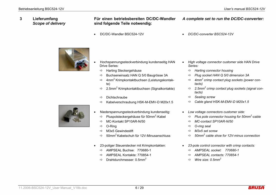
• DC/DC-Wandler BSC524-12V
• DC/DC-converter BSC524-12V
• Hochspannungssteckverbindung kundenseitig HAN Drive Series: Harting Steckergehäuse Buchseneinsatz HAN Q 5/0 Baugrösse 3A 4mm2 Krimpkontaktbuchsen (Leistungskontak-
te) 2.5mm2 Krimpkontaktbuchsen (Signalkontakte)
Dichtschraube Kabelverschraubung HSK-M-EMV-D M20x1.5
• High voltage connector customer side HAN Drive Series: Harting connector housing Plug socket HAN Q 5/0 dimension 3A 4mm2 crimp contact plug sockets (power con-
tacts) 2.5mm2 crimp contact plug sockets (signal con-
tacts) Sealing screw Cable gland HSK-M-EMV-D M20x1.5
• Niederspannungssteckverbindung kundenseitig: Pluspolsteckergehäuse für 50mm2-Kabel MC-Kontakt SP10AR-N/50 O-Ring M3x5 Gewindestift 50mm2 Kabelschuh für 12V-Minusanschluss
• Low voltage connectors customer side: Plus pole connector housing for 50mm2-cable MC-contact SP10AR-N/50 O-ring seal M3x5 set screw 50mm2 cable shoe for 12V-minus connection
• 23-poliger Steuerstecker mit Krimpkontakten: AMPSEAL Buchse: 770680-1 AMPSEAL Kontakte: 770854-1 Drahtdurchmesser: 0.5mm2
• 23-pole control connector with crimp contacts: AMPSEAL socket: 770680-1 AMPSEAL contacts: 770854-1 Wire size: 0.5mm2
Betriebsanleitung BSC524-12V User’s manual BSC524-12V
11.2006-BSC524-12V_User Manual_V18b.doc 7 / 29
4 Spezifikationen Specifications
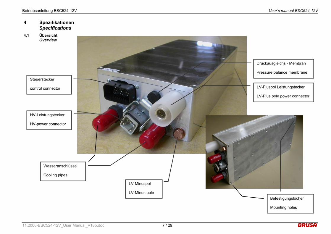
4.1 Übersicht Overview
Wasseranschlüsse Cooling pipes
Druckausgleichs - Membran Pressure balance membrane
HV-Leistungstecker HV-power connector
Steuerstecker control connector LV-Pluspol Leistungstecker
LV-Plus pole power connector
Befestigungslöcher Mounting holes
LV-Minuspol LV-Minus pole

Betriebsanleitung BSC524-12V User’s manual BSC524-12V
11.2006-BSC524-12V_User Manual_V18b.doc 8 / 29
4.2 Einführung Introduction
Der BSC5-12V ist ein bidirektionaler DC/DC-Wandler mit galvanischer Trennung zwischen dem Hochspan-nungs- und Niederspannungskreis. Das Gerät basiert zum einen auf einer serien-resonant arbeitenden Trafo-stufe, durch welche die galvanische Trennung realisiert wird. Zum anderen kann durch zwei zur Rippelreduzie-rung verzahnt arbeitende Hochsetz-/Tiefsetzsteller die gewünschte Spannung im jeweiligen Betriebsmodus eingestellt werden. Aufgrund der resonanten Topologie der Trafostufe und der sogenannten Autokommutierung des Hochsetz-/Tiefsetzstellers werden nicht nur Verlus-te auf ein Minimum begrenzt, sondern auch hervorra-gende EMV-Eigenschaften erreicht.
The BSC5-12V-B is a bidirectional DC/DC-Converter with galvanic insulation between the high voltage and low voltage circuit. The device is based on one hand upon a series-resonant operating transformer stage, which ensures the galvanic insulation. On the other hand two buck/boost-converters, that are operated in-terleaved in order to reduce ripple currents, allow to ad-just the required voltage level in the corresponding op-eration mode. Due to the resonant topology of the transformer stage and the so-called Autocommutation of the buck/boost-converter not only losses are reduced to a minimum but also an excellent EMC-behavior is obtained.
4.3 Terminologie Terminology
• Hochspannung, Leistungsanschluss (HV): Fuel Cell Circuit (FCC), Battery Circuit (BC)
• Niederspannung, Leistungsanschluss (LV): Bordnetz (AUX)
• Niederspannung, Steueranschluss (LV): Bordnetz (AUX)
• High voltage, Power interface (HV): Fuel cell circuit (FCC), Battery circuit (BC)
• Low voltage, Power interface (HV): Auxiliary supply (AUX)
• Low voltage, Control interface (LV): Auxiliary supply (AUX)
4.4 Grenzdaten Absolute maximum ratings
• Maximale Spannung auf Hochspannungsseite: UHVmax = 500V
• Maximale Spannung auf Niederspannungsseite: ULVmax = 25V
• Maximale eingangseitige Kühlwassertemperatur: Twater@inlet = 65°C
• Minimale Durchflussrate des Kühlwassers: vwater = 4l/min
• Umgebungstemperaturbereich bei Betrieb: TUmgebung = -25°C…+85°C
• Umgebungstemperaturbereich bei Nichtbetrieb: TUmgebung = -40C…+105°C
• Maximum voltage on high voltage side: UHVmax = 500V
• Maximum voltage on low voltage side: ULVmax = 25V
• Maximum inlet cooling water temperature: Twater@inlet = 65°C
• Minimum flow rate of cooling water: vwater = 4l/min
• Operating ambient temperature range: Tambient = -25°C…+85°C
• Storage ambient temperature range: Tambient = -40C…+105°C
Betriebsanleitung BSC524-12V User’s manual BSC524-12V
11.2006-BSC524-12V_User Manual_V18b.doc 9 / 29
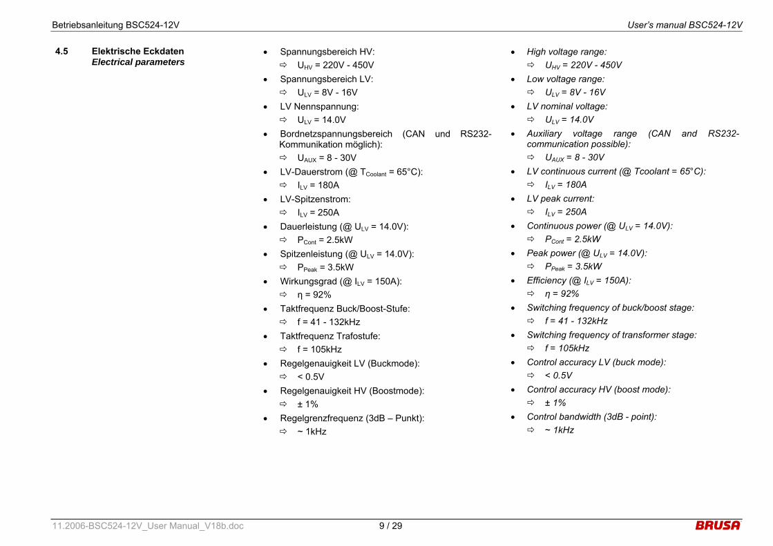
4.5 Elektrische Eckdaten Electrical parameters
• Spannungsbereich HV: UHV = 220V - 450V
• Spannungsbereich LV: ULV = 8V - 16V
• LV Nennspannung: ULV = 14.0V
• Bordnetzspannungsbereich (CAN und RS232-Kommunikation möglich): UAUX = 8 - 30V
• LV-Dauerstrom (@ TCoolant = 65°C): ILV = 180A
• LV-Spitzenstrom: ILV = 250A
• Dauerleistung (@ ULV = 14.0V): PCont = 2.5kW
• Spitzenleistung (@ ULV = 14.0V): PPeak = 3.5kW
• Wirkungsgrad (@ ILV = 150A): η = 92%
• Taktfrequenz Buck/Boost-Stufe: f = 41 - 132kHz
• Taktfrequenz Trafostufe: f = 105kHz
• Regelgenauigkeit LV (Buckmode): < 0.5V
• Regelgenauigkeit HV (Boostmode): ± 1%
• Regelgrenzfrequenz (3dB – Punkt): ~ 1kHz
• High voltage range: UHV = 220V - 450V
• Low voltage range: ULV = 8V - 16V
• LV nominal voltage: ULV = 14.0V
• Auxiliary voltage range (CAN and RS232-communication possible): UAUX = 8 - 30V
• LV continuous current (@ Tcoolant = 65°C): ILV = 180A
• LV peak current: ILV = 250A
• Continuous power (@ ULV = 14.0V): PCont = 2.5kW
• Peak power (@ ULV = 14.0V): PPeak = 3.5kW
• Efficiency (@ ILV = 150A): η = 92%
• Switching frequency of buck/boost stage: f = 41 - 132kHz
• Switching frequency of transformer stage: f = 105kHz
• Control accuracy LV (buck mode): < 0.5V
• Control accuracy HV (boost mode): ± 1%
• Control bandwidth (3dB - point): ~ 1kHz

Betriebsanleitung BSC524-12V User’s manual BSC524-12V
11.2006-BSC524-12V_User Manual_V18b.doc 10 / 29
4.6 Blockschaltbild Block diagram
Resonant galvanically insulated bidirectional DC/DC -converter with constant voltage ratio 12:1
AC DC
DC AC
Low Voltage 8…16 VDC max. 250 A
Max. voltage loss: +/-0,5V
Low voltage
filter
High voltage 220…450 VDC
max. 17A
Resonant bidirectional buck/boost - converter
with variable voltage ratio 0,20…0,83
90..198 VDCmax. 21 A
High voltage
filter 12 : 1
4.7 Mechanische Eckdaten Mechanical parameters
• Dimensionen (Länge x Breite x Höhe): l x b x h = 315 x 150 x 75mm
• Volumen (ohne Stecker): V = 3,5l
• Gewicht (ohne kundenseitige Stecker): m = 5,24kg
• Gehäusedaten: IP65 Aluminium Wasserfeste Druckausgleichsmembran integ-
riert
• Dimensions (length x width x height): l x w x h = 315 x 150 x 75mm
• Volume (without connectors): V = 3,5l
• Weight (without connectors on customer side): m = 5,24kg
• Housing characteristics: IP65 Aluminum Waterproof pressure balance integrated
Betriebsanleitung BSC524-12V User’s manual BSC524-12V
11.2006-BSC524-12V_User Manual_V18b.doc 11 / 29
5 Schnittstellen Interfaces
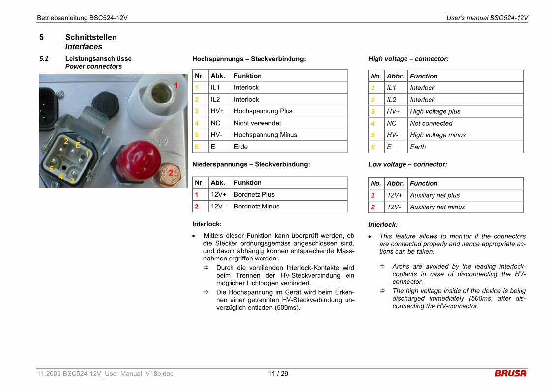
5.1 Leistungsanschlüsse Power connectors
Hochspannungs – Steckverbindung:
Niederspannungs – Steckverbindung:
Interlock:
• Mittels dieser Funktion kann überprüft werden, ob die Stecker ordnungsgemäss angeschlossen sind, und davon abhängig können entsprechende Mass-nahmen ergriffen werden: Durch die voreilenden Interlock-Kontakte wird
beim Trennen der HV-Steckverbindung ein möglicher Lichtbogen verhindert.
Die Hochspannung im Gerät wird beim Erken-nen einer getrennten HV-Steckverbindung un-verzüglich entladen (500ms).
Nr. Abk. Funktion
1 IL1 Interlock
2 IL2 Interlock
3 HV+ Hochspannung Plus
4 NC Nicht verwendet
5 HV- Hochspannung Minus
E E Erde
Nr. Abk. Funktion
1 12V+ Bordnetz Plus
2 12V- Bordnetz Minus
High voltage – connector:
Low voltage – connector:
Interlock:
• This feature allows to monitor if the connectors are connected properly and hence appropriate ac-tions can be taken.
Archs are avoided by the leading interlock-contacts in case of disconnecting the HV-connector.
The high voltage inside of the device is being discharged immediately (500ms) after dis-connecting the HV-connector.
No. Abbr. Function
1 IL1 Interlock
2 IL2 Interlock
3 HV+ High voltage plus
4 NC Not connected
5 HV- High voltage minus
E E Earth
No. Abbr. Function
1 12V+ Auxiliary net plus
2 12V- Auxiliary net minus
2 1
E
3 5
4
1
2
Betriebsanleitung BSC524-12V User’s manual BSC524-12V
11.2006-BSC524-12V_User Manual_V18b.doc 12 / 29
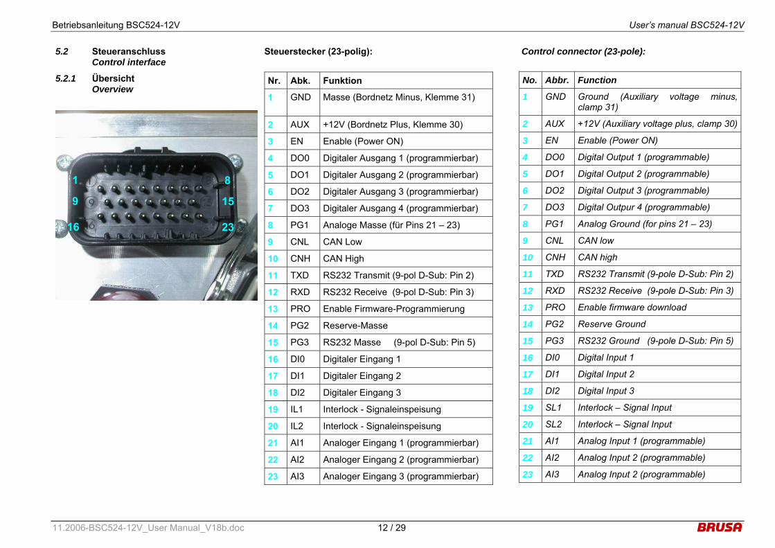
5.2 Steueranschluss Control interface
5.2.1 Übersicht Overview
Steuerstecker (23-polig):
Nr. Abk. Funktion
1 GND Masse (Bordnetz Minus, Klemme 31)
2 AUX +12V (Bordnetz Plus, Klemme 30)
3 EN Enable (Power ON)
4 DO0 Digitaler Ausgang 1 (programmierbar)
5 DO1 Digitaler Ausgang 2 (programmierbar)
6 DO2 Digitaler Ausgang 3 (programmierbar)
7 DO3 Digitaler Ausgang 4 (programmierbar)
8 PG1 Analoge Masse (für Pins 21 – 23)
9 CNL CAN Low
10 CNH CAN High
11 TXD RS232 Transmit (9-pol D-Sub: Pin 2)
12 RXD RS232 Receive (9-pol D-Sub: Pin 3)
13 PRO Enable Firmware-Programmierung
14 PG2 Reserve-Masse
15 PG3 RS232 Masse (9-pol D-Sub: Pin 5)
16 DI0 Digitaler Eingang 1
17 DI1 Digitaler Eingang 2
18 DI2 Digitaler Eingang 3
19 IL1 Interlock - Signaleinspeisung
20 IL2 Interlock - Signaleinspeisung
21 AI1 Analoger Eingang 1 (programmierbar)
22 AI2 Analoger Eingang 2 (programmierbar)
23 AI3 Analoger Eingang 3 (programmierbar)
Control connector (23-pole):
No. Abbr. Function
1 GND Ground (Auxiliary voltage minus, clamp 31)
2 AUX +12V (Auxiliary voltage plus, clamp 30)
3 EN Enable (Power ON)
4 DO0 Digital Output 1 (programmable)
5 DO1 Digital Output 2 (programmable)
6 DO2 Digital Output 3 (programmable)
7 DO3 Digital Outpur 4 (programmable)
8 PG1 Analog Ground (for pins 21 – 23)
9 CNL CAN low
10 CNH CAN high
11 TXD RS232 Transmit (9-pole D-Sub: Pin 2)
12 RXD RS232 Receive (9-pole D-Sub: Pin 3)
13 PRO Enable firmware download
14 PG2 Reserve Ground
15 PG3 RS232 Ground (9-pole D-Sub: Pin 5)
16 DI0 Digital Input 1
17 DI1 Digital Input 2
18 DI2 Digital Input 3
19 SL1 Interlock – Signal Input
20 SL2 Interlock – Signal Input
21 AI1 Analog Input 1 (programmable)
22 AI2 Analog Input 2 (programmable)
23 AI3 Analog Input 2 (programmable)
1
9
16
8
15
23
Betriebsanleitung BSC524-12V User’s manual BSC524-12V
11.2006-BSC524-12V_User Manual_V18b.doc 13 / 29
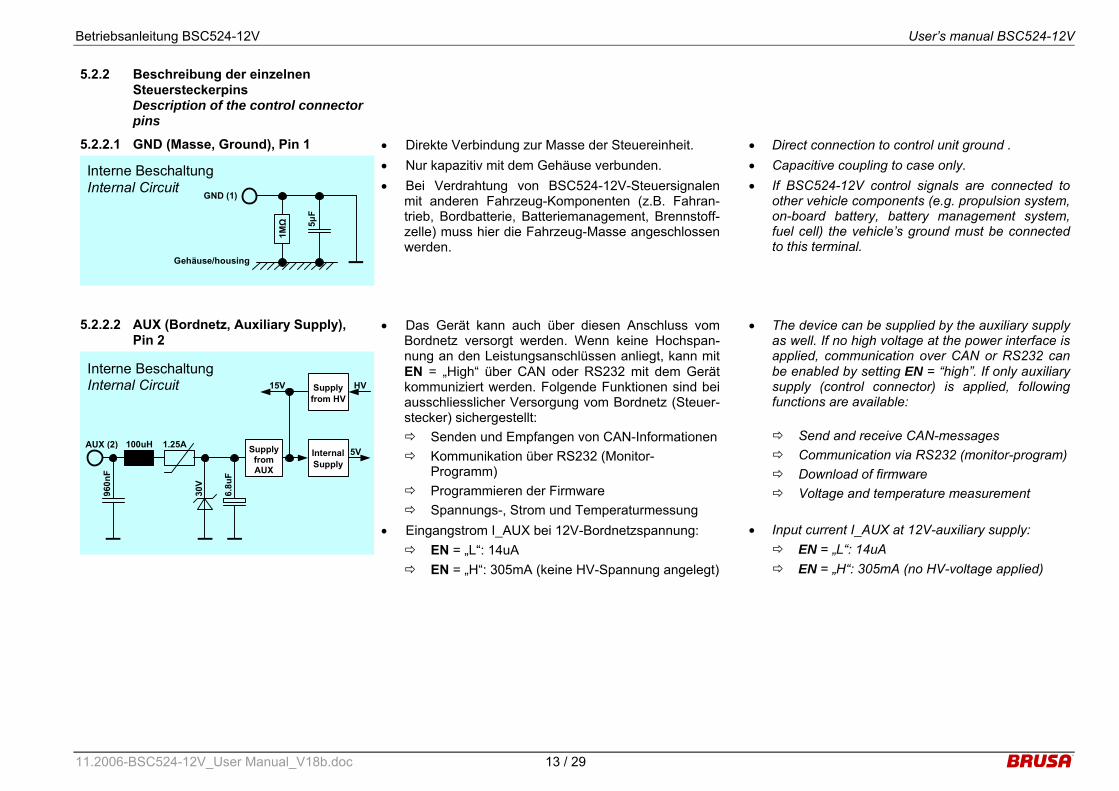
5.2.2 Beschreibung der einzelnen Steuersteckerpins Description of the control connector pins
5.2.2.1 GND (Masse, Ground), Pin 1 Interne Beschaltung Internal Circuit
1MΩ
5µF
GND (1)
Gehäuse/housing
• Direkte Verbindung zur Masse der Steuereinheit. • Nur kapazitiv mit dem Gehäuse verbunden. • Bei Verdrahtung von BSC524-12V-Steuersignalen
mit anderen Fahrzeug-Komponenten (z.B. Fahran-trieb, Bordbatterie, Batteriemanagement, Brennstoff-zelle) muss hier die Fahrzeug-Masse angeschlossen werden.
• Direct connection to control unit ground . • Capacitive coupling to case only. • If BSC524-12V control signals are connected to
other vehicle components (e.g. propulsion system, on-board battery, battery management system, fuel cell) the vehicle’s ground must be connected to this terminal.
5.2.2.2 AUX (Bordnetz, Auxiliary Supply), Pin 2
Interne Beschaltung Internal Circuit
960n
F
AUX (2) 100uH 1.25A5V
30V
InternalSupply
15V
6.8u
F
Supply from HV
HV
Supply from AUX
• Das Gerät kann auch über diesen Anschluss vom Bordnetz versorgt werden. Wenn keine Hochspan-nung an den Leistungsanschlüssen anliegt, kann mit EN = „High“ über CAN oder RS232 mit dem Gerät kommuniziert werden. Folgende Funktionen sind bei ausschliesslicher Versorgung vom Bordnetz (Steuer-stecker) sichergestellt: Senden und Empfangen von CAN-Informationen Kommunikation über RS232 (Monitor-
Programm) Programmieren der Firmware Spannungs-, Strom und Temperaturmessung
• Eingangstrom I_AUX bei 12V-Bordnetzspannung: EN = „L“: 14uA EN = „H“: 305mA (keine HV-Spannung angelegt)
• The device can be supplied by the auxiliary supply as well. If no high voltage at the power interface is applied, communication over CAN or RS232 can be enabled by setting EN = “high”. If only auxiliary supply (control connector) is applied, following functions are available:
Send and receive CAN-messages Communication via RS232 (monitor-program) Download of firmware Voltage and temperature measurement
• Input current I_AUX at 12V-auxiliary supply: EN = „L“: 14uA EN = „H“: 305mA (no HV-voltage applied)

Betriebsanleitung BSC524-12V User’s manual BSC524-12V
11.2006-BSC524-12V_User Manual_V18b.doc 14 / 29
5.2.2.3 EN (Enable, Power ON), Pin 3 Interne Beschaltung Internal Circuit
47nF
EN (3)
5V
4.7kΩ
220p
F 1,0V
3,3V
Schmitt Trigger
22kΩ
4.7kΩ
5V-Supply Enable
10kΩ
• Bei Anlegen einer Spannung an AUX und mit EN = „High“ (+8V...30V) wird das Gerät in den betriebsbe-reiten Modus versetzt. Sinnvollerweise erfolgt dies durch eine Verbindung des Enable-Pins über einen Schalter mit dem Bordnetz.
• Um eine neue Firmware zu programmieren, ist es nicht erforderlich, dass EN = „High“ ist.
• Auch wenn am HV-Stecker Hochspannung anliegt, wird die geräteinterne Logik nur dann versorgt, wenn der Pin EN = „High“ ist.
• By applying a voltage to AUX and by setting EN = „high“ (+8V...30V) the device will be ready to op-erate. Reasonably this is realized by using a switch in order to connect the enable-pin to the auxiliary supply.
• In order to download a new firmware, EN does not have to be „high”.
• Even when high voltage is applied to the HV-connector, the device internal logic is only sup-plied, if the pin EN = „high“.
Betriebsanleitung BSC524-12V User’s manual BSC524-12V
11.2006-BSC524-12V_User Manual_V18b.doc 15 / 29
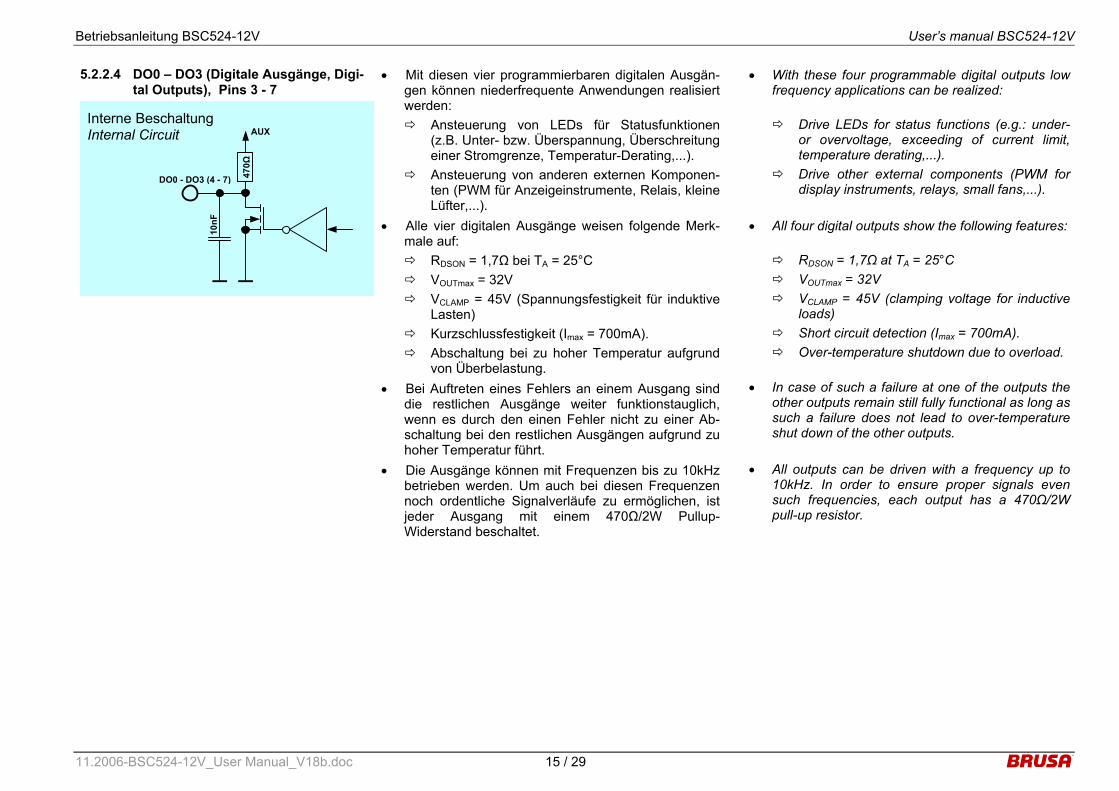
5.2.2.4 DO0 – DO3 (Digitale Ausgänge, Digi-tal Outputs), Pins 3 - 7
Interne Beschaltung Internal Circuit
10nF
DO0 - DO3 (4 - 7)
AUX
470Ω
• Mit diesen vier programmierbaren digitalen Ausgän-gen können niederfrequente Anwendungen realisiert werden: Ansteuerung von LEDs für Statusfunktionen
(z.B. Unter- bzw. Überspannung, Überschreitung einer Stromgrenze, Temperatur-Derating,...).
Ansteuerung von anderen externen Komponen-ten (PWM für Anzeigeinstrumente, Relais, kleine Lüfter,...).
• Alle vier digitalen Ausgänge weisen folgende Merk-male auf: RDSON = 1,7Ω bei TA = 25°C VOUTmax = 32V VCLAMP = 45V (Spannungsfestigkeit für induktive
Lasten) Kurzschlussfestigkeit (Imax = 700mA). Abschaltung bei zu hoher Temperatur aufgrund
von Überbelastung. • Bei Auftreten eines Fehlers an einem Ausgang sind
die restlichen Ausgänge weiter funktionstauglich, wenn es durch den einen Fehler nicht zu einer Ab-schaltung bei den restlichen Ausgängen aufgrund zu hoher Temperatur führt.
• Die Ausgänge können mit Frequenzen bis zu 10kHz betrieben werden. Um auch bei diesen Frequenzen noch ordentliche Signalverläufe zu ermöglichen, ist jeder Ausgang mit einem 470Ω/2W Pullup-Widerstand beschaltet.
• With these four programmable digital outputs low frequency applications can be realized:
Drive LEDs for status functions (e.g.: under- or overvoltage, exceeding of current limit, temperature derating,...).
Drive other external components (PWM for display instruments, relays, small fans,...).
• All four digital outputs show the following features:
RDSON = 1,7Ω at TA = 25°C VOUTmax = 32V VCLAMP = 45V (clamping voltage for inductive
loads) Short circuit detection (Imax = 700mA). Over-temperature shutdown due to overload.
• In case of such a failure at one of the outputs the other outputs remain still fully functional as long as such a failure does not lead to over-temperature shut down of the other outputs.
• All outputs can be driven with a frequency up to 10kHz. In order to ensure proper signals even such frequencies, each output has a 470Ω/2W pull-up resistor.
Betriebsanleitung BSC524-12V User’s manual BSC524-12V
11.2006-BSC524-12V_User Manual_V18b.doc 16 / 29
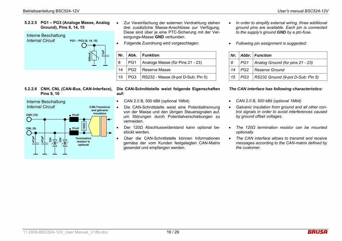
5.2.2.5 PG1 – PG3 (Analoge Masse, Analog Ground), Pins 8, 14, 15
Interne Beschaltung Internal Circuit
1µF
PG1 – PG3 (8, 14, 15)
300m
A
• Zur Vereinfachung der externen Verdrahtung stehen drei zusätzliche Masse-Anschlüsse zur Verfügung. Diese sind über je eine PTC-Sicherung mit der Ver-sorgungs-Masse GND verbunden.
• Folgende Zuordnung wird vorgeschlagen: Nr. Abk. Funktion
8 PG1 Analoge Masse (für Pins 21 - 23)
14 PG2 Reserve Masse
15 PG3 RS232 - Masse (9-pol D-Sub: Pin 5)
• In order to simplify external wiring, three additional ground pins are available. Each pin is connected to the supply’s ground GND by a ptc-fuse.
• Following pin assignment is suggested: Nr. Abbr. Function
8 PG1 Analog Ground (for pins 21 - 23)
14 PG2 Reserve Ground
15 PG3 RS232 Ground (9-pol D-Sub: Pin 5)
5.2.2.6 CNH, CNL (CAN-Bus, CAN-Interface), Pins 9, 10
Interne Beschaltung Internal Circuit
47pF
CNL (9)
33V
51uH
47pF
CNH (10)
120Ω
33V
51uH
Termination resistor is optional
CAN-Transeiver and galvanic
insulation
Die CAN-Schnittstelle weist folgende Eigenschaften auf:
• CAN 2.0 B, 500 kBit (optional 1Mbit) • Die CAN-Schnittstelle weist eine Potentialtrennung
von der Masse und den übrigen Steuersignalen auf, um Störungen durch Potentialverschiebungen zu vermeiden.
• Der 120Ω Abschlusswiderstand kann optional be-stückt werden.
• Über die CAN-Schnittstelle können Informationen gemäss der vom Kunden festgelegten CAN-Matrix gesendet und empfangen werden.
The CAN interface has following characteristics: • CAN 2.0 B, 500 kBit (optional 1Mbit) • Galvanic insulation from ground and all other con-
trol signals in order to avoid interferences caused by ground offset voltages.
• The 120Ω termination resistor can be mounted optionally.
• The CAN interface allows to transmit and receive messages according to the CAN-matrix defined by the customer.
Betriebsanleitung BSC524-12V User’s manual BSC524-12V
11.2006-BSC524-12V_User Manual_V18b.doc 17 / 29
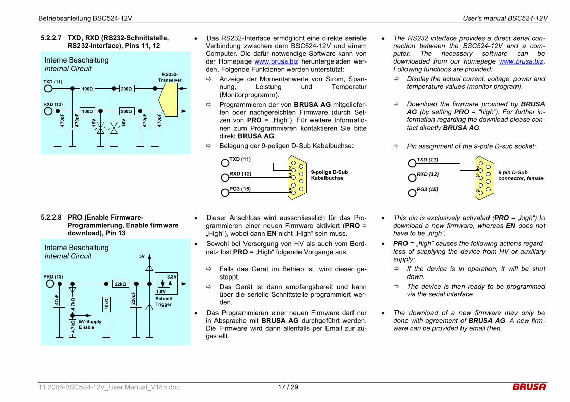
5.2.2.7 TXD, RXD (RS232-Schnittstelle, RS232-Interface), Pins 11, 12
Interne Beschaltung Internal Circuit
470p
F
RXD (12)
10V
470p
F TXD (11)
15V
RS232-Transeiver
200Ω
200Ω
470p
F
470p
F
100Ω
100Ω
• Das RS232-Interface ermöglicht eine direkte serielle Verbindung zwischen dem BSC524-12V und einem Computer. Die dafür notwendige Software kann von der Homepage www.brusa.biz heruntergeladen wer-den. Folgende Funktionen werden unterstützt: Anzeige der Momentanwerte von Strom, Span-
nung, Leistung und Temperatur(Monitorprogramm).
Programmieren der von BRUSA AG mitgeliefer-ten oder nachgereichten Firmware (durch Set-zen von PRO = „High“). Für weitere Informatio-nen zum Programmieren kontaktieren Sie bitte direkt BRUSA AG.
Belegung der 9-poligen D-Sub Kabelbuchse:
RXD (12)
TXD (11)
9-polige D-Sub Kabelbuchse
PG3 (15) 5
23
• The RS232 interface provides a direct serial con-nection between the BSC524-12V and a com-puter. The necessary software can be downloaded from our homepage www.brusa.biz. Following functions are provided: Display the actual current, voltage, power and
temperature values (monitor program).
Download the firmware provided by BRUSA AG (by setting PRO = “high”). For further in-formation regarding the download please con-tact directly BRUSA AG.
Pin assignment of the 9-pole D-sub socket:
RXD (12)
TXD (11)
9 pin D-Sub connector, female
PG3 (15) 5
23
5.2.2.8 PRO (Enable Firmware-
Programmierung, Enable firmware download), Pin 13
Interne Beschaltung Internal Circuit
47nF
PRO (13)
5V
4.7kΩ
220p
F 1,0V
3,3V
Schmitt Trigger
22kΩ
4.7kΩ
5V-Supply Enable
10kΩ
• Dieser Anschluss wird ausschliesslich für das Pro-grammieren einer neuen Firmware aktiviert (PRO = „High“), wobei dann EN nicht „High“ sein muss.
• Sowohl bei Versorgung von HV als auch vom Bord-netz löst PRO = „High“ folgende Vorgänge aus:
Falls das Gerät im Betrieb ist, wird dieser ge-stoppt.
Das Gerät ist dann empfangsbereit und kann über die serielle Schnittstelle programmiert wer-den.
• Das Programmieren einer neuen Firmware darf nur in Absprache mit BRUSA AG durchgeführt werden. Die Firmware wird dann allenfalls per Email zur zu-gestellt.
• This pin is exclusively activated (PRO = „high“) to download a new firmware, whereas EN does not have to be „high”.
• PRO = „high” causes the following actions regard-less of supplying the device from HV or auxiliary supply: If the device is in operation, it will be shut
down. The device is then ready to be programmed
via the serial interface.
• The download of a new firmware may only be done with agreement of BRUSA AG. A new firm-ware can be provided by email then.

Betriebsanleitung BSC524-12V User’s manual BSC524-12V
11.2006-BSC524-12V_User Manual_V18b.doc 18 / 29
5.2.2.9 DI0 – DI2 (Digitale Eingänge, Digital Inputs), Pins 16 – 18
Interne Beschaltung Internal Circuit
10nF
DI0 – DI2 (16 - 18)
5V
220p
F 1,0V
3,3V
SchmittTrigger
22kΩ 10
kΩ
• Mit diesen drei Eingängen können verschiedene Funktionen realisiert werden wie folgender Vorschlag zeigt: DI0: Hochsetzbetrieb DI1: Tiefsetzbetrieb DI2: Spannungs- oder Stromregelmodus
• With these three inputs various functions can be realized as the following proposal shows:
DI0: Boost mode DI1: Buck mode DI2: Voltage or current regulation mode
5.2.2.10 IL1, IL2 (Interlock), Pins 19, 20 Interne Beschaltung Internal Circuit
10nF
IL1 (19)
IL2 (20)
IL1 (1)
IL2 (2)
High voltage power connector
12mH
12mH
10nF
470p
F
470p
F
51uH
51uH Internal Interlock Processing
• Die Interlock-Verbindung ist eine sicherheitsrelevan-te Funktion, die intern verarbeitet wird, aber auch durch ein übergeordnetes System (Bsp.: Fahrzeug-system) ausgewertet werden kann. Die Interlock-Verbindung ist durch die HV-Steckverbindung ge-schleift (Brücke im HV-Stecker notwendig) und er-laubt so die Überprüfung, ob dieser Stecker ord-nungsgemäss angeschlossen ist.
• Die Interlockverbindung ist für einen Strom bis 100mA ausgelegt.
• Falls im übergeordneten System eine Auswertung gewünscht ist, muss das Interlock-Signal bei Pin 19 bzw. 20 eingespeist (Stromquelle) werden, wobei die Polarität keine Rolle spielt.
• Falls der HV- oder Kontrollstecker nicht richtig kon-taktiert sind, ist die Schleife offen und es wird intern immer ein Fehler erkannt. Dies führt unverzüglich zum Abschalten des Geräts.
• Die LV-Steckverbindung ist im Interlockkreis nicht in-tegriert!
• The interlock is a safety relevant function, which is processed internally but may also be valuated by a superior system (e.g.: vehicle system). The in-terlock is looped through the HV-connection (bridge in HV connector necessary) and allows therefore to monitor, if this connector is connected properly to the device.
• The interlock is designed for a current up to 100mA.
• If in the superior system the interlock shall be con-sidered, the interlock-signal has to be provided at pin 19 resp. 20 (current source), whereas the po-larity does not have to be considered.
• If the HV- or control connector is not connected properly to the device, the loop is open and an er-ror is always detected internally. This leads to an immediate shut-down of the device.
• The LV-connection is not integrated in the inter-lock-circuit!
Betriebsanleitung BSC524-12V User’s manual BSC524-12V
11.2006-BSC524-12V_User Manual_V18b.doc 19 / 29
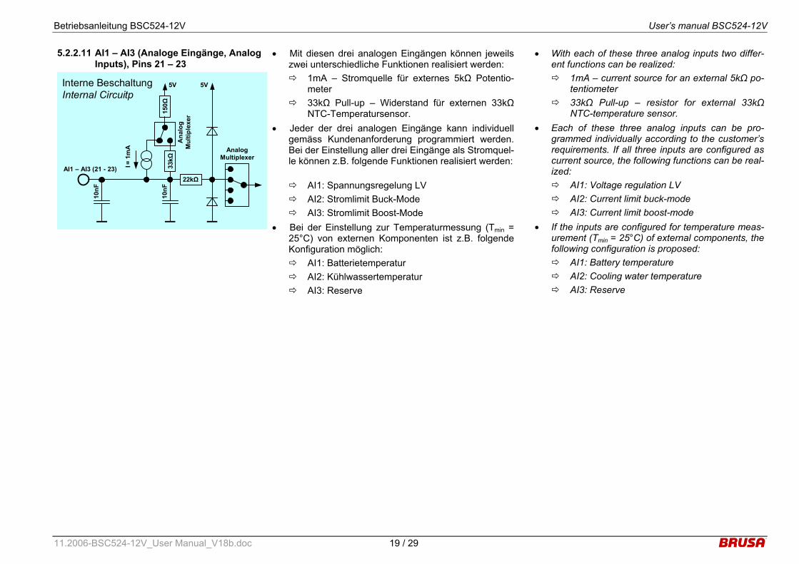
5.2.2.11 AI1 – AI3 (Analoge Eingänge, Analog Inputs), Pins 21 – 23
Interne Beschaltung Internal Circuitp
10nF
AI1 – AI3 (21 - 23)
5V
Analog Multiplexer
22kΩ
150Ω
33
kΩ
10nF
I = 1
mA
5V
Ana
log
Mul
tiple
xer
• Mit diesen drei analogen Eingängen können jeweils zwei unterschiedliche Funktionen realisiert werden: 1mA – Stromquelle für externes 5kΩ Potentio-
meter 33kΩ Pull-up – Widerstand für externen 33kΩ
NTC-Temperatursensor. • Jeder der drei analogen Eingänge kann individuell
gemäss Kundenanforderung programmiert werden. Bei der Einstellung aller drei Eingänge als Stromquel-le können z.B. folgende Funktionen realisiert werden:
AI1: Spannungsregelung LV AI2: Stromlimit Buck-Mode AI3: Stromlimit Boost-Mode
• Bei der Einstellung zur Temperaturmessung (Tmin = 25°C) von externen Komponenten ist z.B. folgende Konfiguration möglich: AI1: Batterietemperatur AI2: Kühlwassertemperatur AI3: Reserve
• With each of these three analog inputs two differ-ent functions can be realized: 1mA – current source for an external 5kΩ po-
tentiometer 33kΩ Pull-up – resistor for external 33kΩ
NTC-temperature sensor. • Each of these three analog inputs can be pro-
grammed individually according to the customer’s requirements. If all three inputs are configured as current source, the following functions can be real-ized: AI1: Voltage regulation LV AI2: Current limit buck-mode AI3: Current limit boost-mode
• If the inputs are configured for temperature meas-urement (Tmin = 25°C) of external components, the following configuration is proposed: AI1: Battery temperature AI2: Cooling water temperature AI3: Reserve
Betriebsanleitung BSC524-12V User’s manual BSC524-12V
11.2006-BSC524-12V_User Manual_V18b.doc 20 / 29
6 Inbetriebnahme des Gerätes Start-up the device
6.1 Anschluss des Gerätes Connecting the device
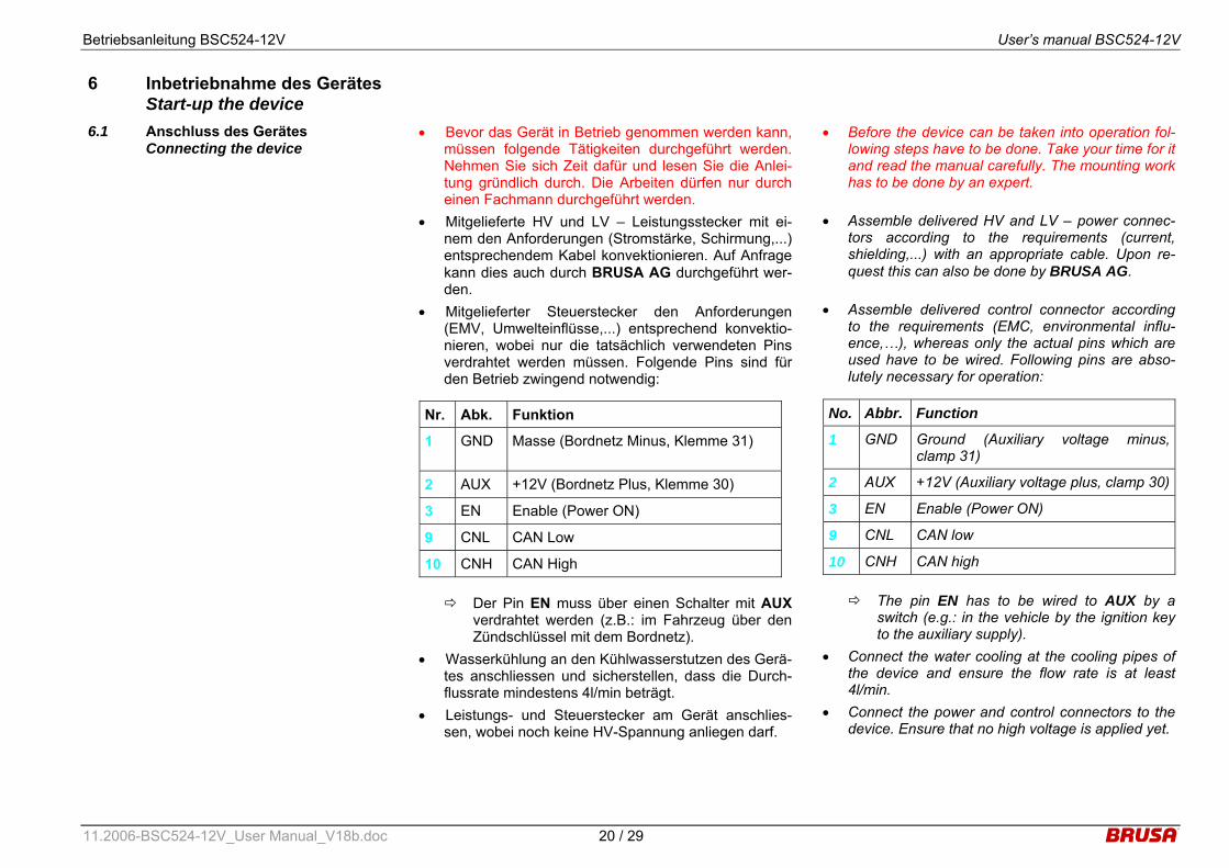
• Bevor das Gerät in Betrieb genommen werden kann, müssen folgende Tätigkeiten durchgeführt werden. Nehmen Sie sich Zeit dafür und lesen Sie die Anlei-tung gründlich durch. Die Arbeiten dürfen nur durch einen Fachmann durchgeführt werden.
• Mitgelieferte HV und LV – Leistungsstecker mit ei-nem den Anforderungen (Stromstärke, Schirmung,...) entsprechendem Kabel konvektionieren. Auf Anfrage kann dies auch durch BRUSA AG durchgeführt wer-den.
• Mitgelieferter Steuerstecker den Anforderungen (EMV, Umwelteinflüsse,...) entsprechend konvektio-nieren, wobei nur die tatsächlich verwendeten Pins verdrahtet werden müssen. Folgende Pins sind für den Betrieb zwingend notwendig:
Der Pin EN muss über einen Schalter mit AUX
verdrahtet werden (z.B.: im Fahrzeug über den Zündschlüssel mit dem Bordnetz).
• Wasserkühlung an den Kühlwasserstutzen des Gerä-tes anschliessen und sicherstellen, dass die Durch-flussrate mindestens 4l/min beträgt.
• Leistungs- und Steuerstecker am Gerät anschlies-sen, wobei noch keine HV-Spannung anliegen darf.
Nr. Abk. Funktion
1 GND Masse (Bordnetz Minus, Klemme 31)
2 AUX +12V (Bordnetz Plus, Klemme 30)
3 EN Enable (Power ON)
9 CNL CAN Low
10 CNH CAN High
• Before the device can be taken into operation fol-lowing steps have to be done. Take your time for it and read the manual carefully. The mounting work has to be done by an expert.
• Assemble delivered HV and LV – power connec-tors according to the requirements (current, shielding,...) with an appropriate cable. Upon re-quest this can also be done by BRUSA AG.
• Assemble delivered control connector according to the requirements (EMC, environmental influ-ence,…), whereas only the actual pins which are used have to be wired. Following pins are abso-lutely necessary for operation:
The pin EN has to be wired to AUX by a
switch (e.g.: in the vehicle by the ignition key to the auxiliary supply).
• Connect the water cooling at the cooling pipes of the device and ensure the flow rate is at least 4l/min.
• Connect the power and control connectors to the device. Ensure that no high voltage is applied yet.
No. Abbr. Function
1 GND Ground (Auxiliary voltage minus, clamp 31)
2 AUX +12V (Auxiliary voltage plus, clamp 30)
3 EN Enable (Power ON)
9 CNL CAN low
10 CNH CAN high
Betriebsanleitung BSC524-12V User’s manual BSC524-12V
11.2006-BSC524-12V_User Manual_V18b.doc 21 / 29
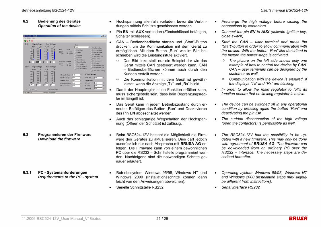
6.2 Bedienung des Gerätes Operation of the device
• Hochspannung allenfalls vorladen, bevor die Verbin-dungen mittels Schütze geschlossen werden.
• Pin EN mit AUX verbinden (Zündschlüssel betätigen, Schalter schliessen).
• CAN – Bedienoberfläche starten und „Start“-Button drücken, um die Kommunikation mit dem Gerät zu ermöglichen. Mit dem Button „Run“ wie im Bild be-schrieben wird die Leistungsstufe aktiviert. Das Bild links stellt nur ein Beispiel dar wie das
Gerät mittels CAN gesteuert werden kann. CAN – Bedienoberflächen können auch durch den Kunden erstellt werden.
Die Kommunikation mit dem Gerät ist gewähr-leistet, wenn die Anzeige „Tx“ und „Rx“ blinkt.
• Damit der Hauptregler seine Funktion erfüllen kann, muss sichergestellt sein, dass kein Begrenzungsreg-ler im Eingriff ist.
• Das Gerät kann in jedem Betriebszustand durch er-neutes Betätigen des Button „Run“ und Deaktivieren des Pin EN abgeschaltet werden.
• Auch das schlagartige Wegschalten der Hochspan-nung (Öffnen der Schütze) ist zulässig.
• Precharge the high voltage before closing the connections by contactors.
• Connect the pin EN to AUX (activate ignition key, close switch).
• Start the CAN – user terminal and press the “Start”-button in order to allow communication with the device. With the button “Run” like described in the picture the power stage is activated. The picture on the left side shows only one
example of how to control the device by CAN. CAN – user terminals can be designed by the customer as well.
Communication with the device is ensured, if the displays “Tx” and “Rx” are blinking.
• In order to allow the main regulator to fulfill its function ensure that no limiting regulator is active.
• The device can be switched off in any operational condition by pressing again the button “Run” and deactivating the pin EN.
• The sudden disconnection of the high voltage (open the contactors) is permissible as well.
6.3 Programmieren der Firmware Download the firmware
• Beim BSC524-12V besteht die Möglichkeit die Firm-ware des Gerätes zu aktualisieren. Dies darf jedoch ausdrücklich nur nach Absprache mit BRUSA AG er-folgen. Die Firmware kann von einem gewöhnlichen PC über die RS232 – Schnittstelle programmiert wer-den. Nachfolgend sind die notwendigen Schritte ge-nauer erläutert.
• The BSC524-12V has the possibility to be up-dated with a new firmware. This may only be done with agreement of BRUSA AG. The firmware can be downloaded from an ordinary PC over the RS232 – interface. The necessary steps are de-scribed hereafter.
6.3.1 PC - Systemanforderungen Requirements to the PC - system
• Betriebssystem Windows 95/98, Windows NT und Windows 2000 (Installationsschritte können dann leicht von den Anweisungen abweichen).
• Serielle Schnittstelle RS232
• Operating system Windows 95/98, Windows NT and Windows 2000 (Installation steps may slightly be different from instructions).
• Serial interface RS232
Betriebsanleitung BSC524-12V User’s manual BSC524-12V
11.2006-BSC524-12V_User Manual_V18b.doc 22 / 29
6.3.2 Einstellungen am Gerät und PC Configuration of the device and PC
• Verbinden Sie den Pin PRO (Pin 13 des Steuerste-ckers) mit dem Pin AUX (Pin 2 des Steuersteckers).
• Stellen Sie eine Verbindung der RS232 – Schnittstel-le am Gerät mit der seriellen Schnittstelle COM1 am Computer her.
• Stellen Sie sicher, dass die RS232 – Schnittstelle am Computer von keiner anderen Anwendung belegt ist.
• Versorgen Sie das Gerät entweder von Hochspan-nung oder vom Bordnetz.
• Für detailierte Informationen bezüglich der Verdrah-tung siehe unter 5.2 Steueranschluss.
• Connect the pin PRO (pin 13 of control connector) with the pin AUX (pin 2 of control connector).
• Provide a connection of the RS232 – interface at the device with the serial interface COM1 at the computer.
• Ensure that the RS232 – interface at the computer is not used by another application.
• Supply the device either from high voltage or from the auxiliary supply.
• For further information regarding the wiring refer to 5.2 control connector.
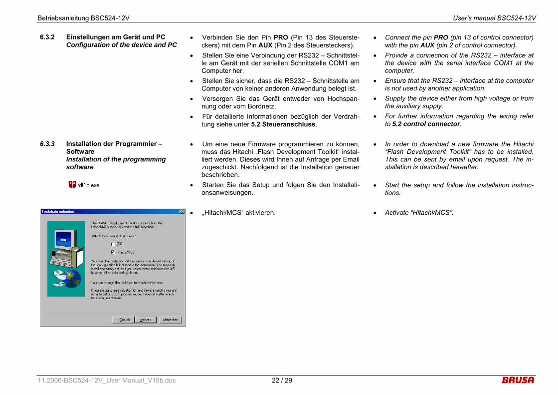
6.3.3 Installation der Programmier – Software Installation of the programming software
• Um eine neue Firmware programmieren zu können, muss das Hitachi „Flash Development Toolkit“ instal-liert werden. Dieses wird Ihnen auf Anfrage per Email zugeschickt. Nachfolgend ist die Installation genauer beschrieben.
• Starten Sie das Setup und folgen Sie den Installati-onsanweisungen.
• In order to download a new firmware the Hitachi “Flash Development Toolkit” has to be installed. This can be sent by email upon request. The in-stallation is described hereafter.
• Start the setup and follow the installation instruc-tions.
• „Hitachi/MCS“ aktivieren. • Activate “Hitachi/MCS”.
Betriebsanleitung BSC524-12V User’s manual BSC524-12V
11.2006-BSC524-12V_User Manual_V18b.doc 23 / 29
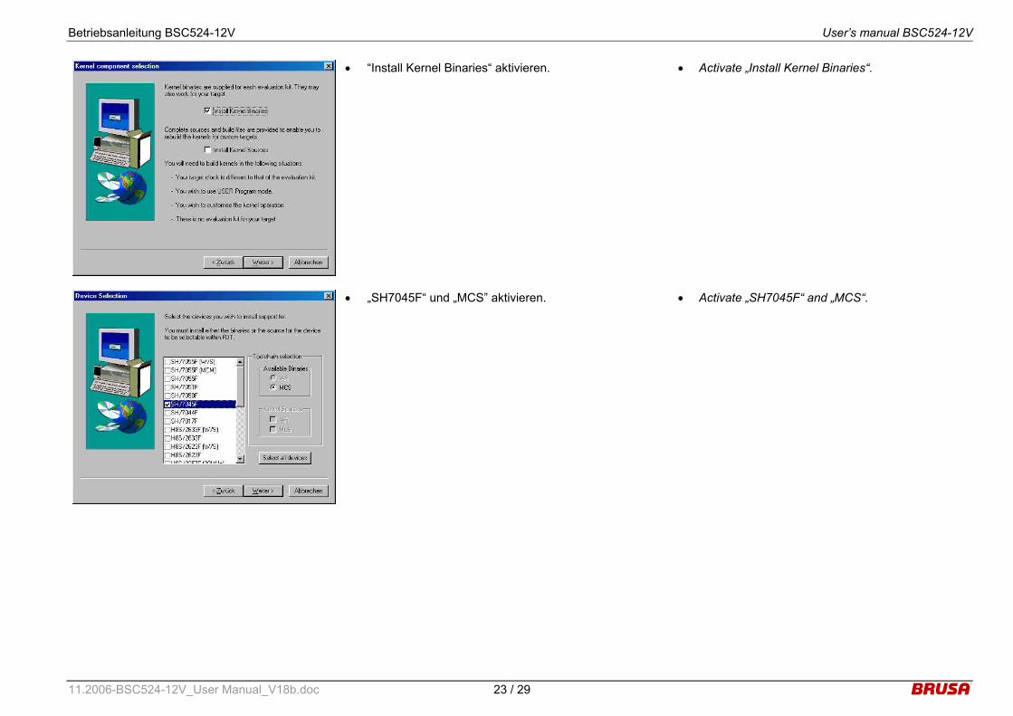
• “Install Kernel Binaries“ aktivieren. • Activate „Install Kernel Binaries“.
• „SH7045F“ und „MCS” aktivieren. • Activate „SH7045F“ and „MCS“.
Betriebsanleitung BSC524-12V User’s manual BSC524-12V
11.2006-BSC524-12V_User Manual_V18b.doc 24 / 29
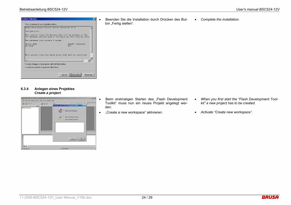
• Beenden Sie die Installation durch Drücken des But-ton „Fertig stellen“.
• Complete the installation.
6.3.4 Anlegen eines Projektes Create a project
• Beim erstmaligen Starten des „Flash Development Toolkit“ muss nun ein neues Projekt angelegt wer-den.
• „Create a new workspace“ aktivieren.
• When you first start the “Flash Development Tool-kit” a new project has to be created.
• Activate “Create new workspace”.

Betriebsanleitung BSC524-12V User’s manual BSC524-12V
11.2006-BSC524-12V_User Manual_V18b.doc 25 / 29
• Im Feld „Workspace Name“ geben Sie “SHC1” ein. • Im Feld „Location“ geben Sie den von Ihnen ge-
wünschten Programmpfad ein.
• Insert „SHC1“ in the field „Workspace Name“. • Insert the corresponding program directory in the
field “Location”.
• Bestätigen Sie mit „Ja“. • Confirm with “Yes”.
• Im Feld „Project Name“ geben Sie den gewünschten Projektnamen ein (z.B.: BSC524-12V).
• Insert an appropriate project name in the field “Project Name” (e.g.: BSC524-12V).
Betriebsanleitung BSC524-12V User’s manual BSC524-12V
11.2006-BSC524-12V_User Manual_V18b.doc 26 / 29
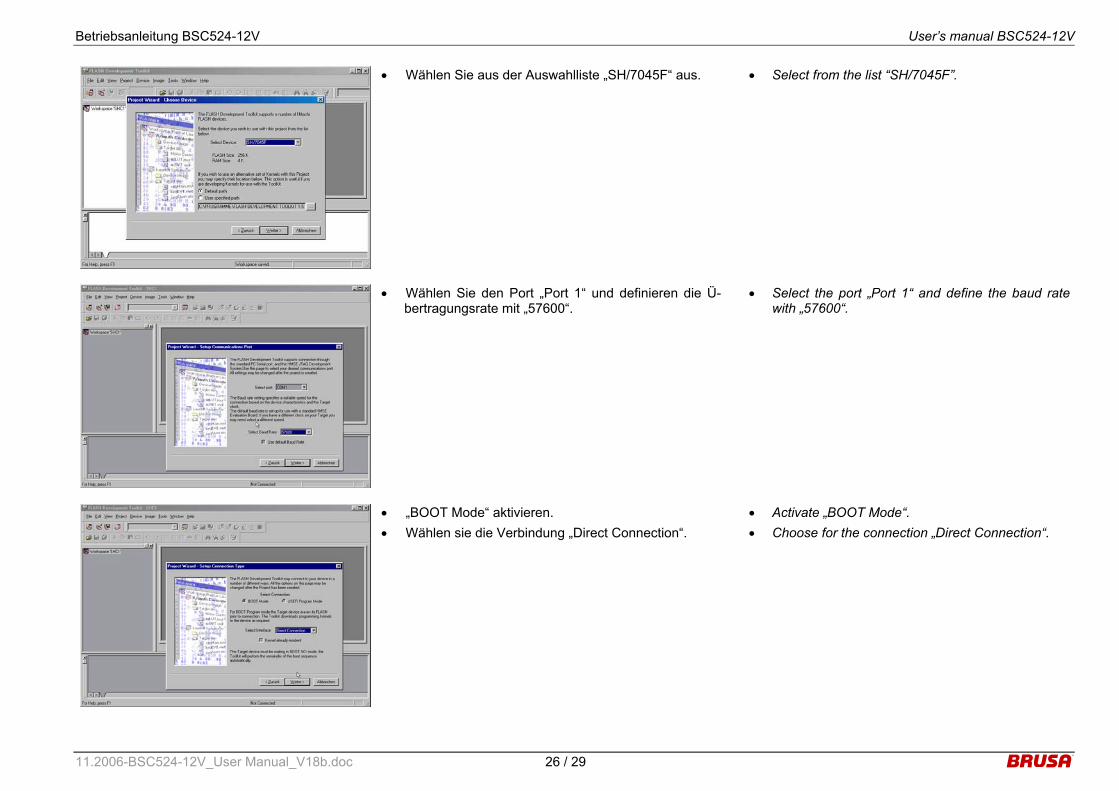
• Wählen Sie aus der Auswahlliste „SH/7045F“ aus. • Select from the list “SH/7045F”.
• Wählen Sie den Port „Port 1“ und definieren die Ü-bertragungsrate mit „57600“.
• Select the port „Port 1“ and define the baud rate with „57600“.
• „BOOT Mode“ aktivieren. • Wählen sie die Verbindung „Direct Connection“.
• Activate „BOOT Mode“. • Choose for the connection „Direct Connection“.

Betriebsanleitung BSC524-12V User’s manual BSC524-12V
11.2006-BSC524-12V_User Manual_V18b.doc 27 / 29
• „Interactive“ und „Standard“ aktivieren. • Activate „Interactive“ and „Standard“.
• Wählen Sie im Menüpunkt „Tools” → “Customize” → “General“ folgende Einstellungen: Verifikation nach dem Programmieren? „No“. Resetieren des Gerätes beim Trennen? „Query“. „Reload last Workspace as startup“ aktivieren.
• Choose in the menu „Tools” → “Customize” → “General“ following configuration:
• Verification after programming? „No“. • Reset the device when disconnecting? „Query“. • Activate „Reload last Workspace as startup“.

Betriebsanleitung BSC524-12V User’s manual BSC524-12V
11.2006-BSC524-12V_User Manual_V18b.doc 28 / 29
6.3.5 Download der Firmware Download of the firmware
• Mit der rechten Maustaste auf den Ordner “Target Fi-les” klicken.
• Mit dem Befehl „Add Files to Project“ kann die Firm-ware (*.mot) aus dem entsprechendem Verzeichnis ausgewählt werden.
• Click with the right mouse button on the folder “Target Files”.
• With the command “Add Files to Project” the firm-ware (*.mot) can be selected from the correspond-ing directory.
• Mit der rechten Maustaste auf die gewünschte Firm-ware klicken und den Befehl “Download file to device” wählen.
• Der Programmiervorgang wird nun gestartet.
• Click with the right mouse button on the firmware which you wish to download and then choose the command „Download file to device“.
• The programming process starts now.
• Nach erfolgreichem Download der Firmware er-scheint im unteren Fenster „Image successfully writ-ten to device“.
• Damit ist der Programmiervorgang beendet und der Pin PRO kann wieder auf „Low“ gesetzt werden.
• Das Gerät ist nun wieder betriebsbereit. • ACHTUNG: Der Download – Vorgang muss vollstän-
dig und fehlerfrei durchgeführt werden. Es muss im-mer die Meldung „Image successfully writen to devi-ce“ erscheinen.
• After successful download of the firmware the message “Image successfully written to device” appears in the lower window.
• Hence the download process is completed and the pin PRO can be set “low” again.
• The device is now ready to operate again. • Attention: The download process has to be done
completely and faultlessly. The message “Image successfully written to device” has always to ap-pear.
Betriebsanleitung BSC524-12V User’s manual BSC524-12V
11.2006-BSC524-12V_User Manual_V18b.doc 29 / 29
7 Garantie Warranty
• Wir gewähren eine Garantie von 24 Monaten ab dem Kaufdatum auf Material- und Verarbeitungs-fehler.
• Die Garantie erlischt bei unsachgemässer Behand-lung des Gerätes.
• Technische Änderungen sind jederzeit ohne An-kündigung möglich.
• Wir weisen ausdrücklich darauf hin, dass mit die-sem Gerät lebensgefährliche Spannungen verarbei-tet werden können. Wir lehnen diesbezüglich jede Haftung ab.
• Wir übernehmen keine Haftung durch Folgeschä-den, die durch die Anwendung dieses Gerätes ent-standen sind.
• We assure a warranty for a period of 24 month from the date of purchase for defects of material and by workmanship.
• Improper use or handling of the product causes the warranty to be void.
• Specifications are subject to change without notice.
• Note that this device processes lethal voltages. We cannot accept any liability concerning this danger.
• We cannot accept any liability for consequential
damages which arose from the use of this device.


![ID~I+';'-l] (1) - dewan.buet.ac.bd · • As the ripple voltage increases the average (dc) OIP voltage decreases V de = V-1/2(Vr) de = V p ....:O.SCf HW dc Voltage • Ripple factor](https://static.fdocuments.in/doc/165x107/5e4e30eb400f971983186181/idi-l-1-dewanbuetacbd-a-as-the-ripple-voltage-increases-the-average.jpg)