Trajectory Optimization of Robots with Regenerative Drive ...

DC3R Regenerative DC DriveUser Guide1/4 to 2 HP, 115/230 VAC
Instruction Manual D2-3453

ATTENTION: Identifies information about practices or circumstancesthat can lead to personal injury or death, property damage, or economicloss.
The information in this manual is subject to change without notice.
Throughout this manual, the following notes are used to alert you to safetyconsiderations:
mIMPORTANT: Identifies information that is critical for successful application andunderstanding of the product.
ATTENTION: The control circuit is at line potential when the drive isenergized. Use a non-metallic screwdriver when making adjustments tothe circuit board potentiometers. Exercise extreme caution ashazardous voltage exists. Failure to observe these precautions couldresult in severe bodily injury of loss of life.
ATTENTION: Only qualified personnel familiar with the construction andoperation of this equipment and the hazards involved should install,adjust, operate, and/or service this equipment. Read and understandthis instruction manual in its entirety before proceeding. Failure toobserve this precaution could result in severe bodily injury or loss of life.
ATTENTION: The user is responsible for conforming with all applicablelocal and national codes. Failure to observe this precaution could resultin severe bodily injury or loss of life.
ATTENTION: It is possible for a drive to run at full speed as a result of acomponent failure. Please ensure that a master switch has been placedin the AC line to stop the drive in an emergency.
ATTENTION: Reduce the chance of an electrical fire, shock, orexplosion by proper grounding, over-current protection, thermalprotection and enclosure. Follow sound maintenance procedures.
m
Trademarks not belonging to Rockwell Automation are property of their respective companies.
©1999 Rockwell International Corporation.

ATTENTION: Starting and Stopping with the inhibit terminal pins doesnot disconnect AC power in the stop position; a hardwired AC powerdisconnection switch must be mounted in close proximity to theoperator’s start/stop controls. This is required, as the DC3 drive doesnot have an armature loop contactor. A single fault like a power deviceshort may cause motor rotation when in the stop mode. The user isresponsible for assuring safe conditions for operating personnel byproviding suitable guards, audio or visual alarms, or other devices.Failure to observe these precautions could result in bodily injury.
ATTENTION: This Drive contains ESD (Electric Static Discharge)sensitive parts and assemblies, Static control precautions are requiredwhen installing, testing, servicing, or repairing this assembly. Failure toobserve these precautions could result in damage to, or destruction of,the equipment.
iii
m

iv
ContentsSpecifications 1
Dimensions 3
Installation 6Wiring . . . . . . . . . . . . . . . . . . . . . . . . . . . . . . . . . . . . . . . . . . . . . . . . . . . . . . . . . . . . . . . . . . . . .6
Shielding guidelines . . . . . . . . . . . . . . . . . . . . . . . . . . . . . . . . . . . . . . . . . . . . . . . . . . . . . . . .7Input isolation transformers . . . . . . . . . . . . . . . . . . . . . . . . . . . . . . . . . . . . . . . . . . . . . . . . . . . . .8Mounting chassis drives . . . . . . . . . . . . . . . . . . . . . . . . . . . . . . . . . . . . . . . . . . . . . . . . . . . . . . .9Mounting enclosed drives . . . . . . . . . . . . . . . . . . . . . . . . . . . . . . . . . . . . . . . . . . . . . . . . . . . .10Heat sinking . . . . . . . . . . . . . . . . . . . . . . . . . . . . . . . . . . . . . . . . . . . . . . . . . . . . . . . . . . . . . . .10Field output . . . . . . . . . . . . . . . . . . . . . . . . . . . . . . . . . . . . . . . . . . . . . . . . . . . . . . . . . . . . . . . .11Cage-clamp terminal block . . . . . . . . . . . . . . . . . . . . . . . . . . . . . . . . . . . . . . . . . . . . . . . . . . . .11Tachogenerator feedback . . . . . . . . . . . . . . . . . . . . . . . . . . . . . . . . . . . . . . . . . . . . . . . . . . . . .12Connections . . . . . . . . . . . . . . . . . . . . . . . . . . . . . . . . . . . . . . . . . . . . . . . . . . . . . . . . . . . . . . .13
Chassis drive connections . . . . . . . . . . . . . . . . . . . . . . . . . . . . . . . . . . . . . . . . . . . . . . . . . .13Enclosed drive connections . . . . . . . . . . . . . . . . . . . . . . . . . . . . . . . . . . . . . . . . . . . . . . . . .14
Speed adjust potentiometer installation . . . . . . . . . . . . . . . . . . . . . . . . . . . . . . . . . . . . . . . . . . .15Speed adjust potentiometer connections . . . . . . . . . . . . . . . . . . . . . . . . . . . . . . . . . . . . . . . . . .16Line Fusing for DC3R Drives . . . . . . . . . . . . . . . . . . . . . . . . . . . . . . . . . . . . . . . . . . . . . . . . . .17+15 and –15 terminals . . . . . . . . . . . . . . . . . . . . . . . . . . . . . . . . . . . . . . . . . . . . . . . . . . . . . . .17Voltage follower . . . . . . . . . . . . . . . . . . . . . . . . . . . . . . . . . . . . . . . . . . . . . . . . . . . . . . . . . . . .18
Operation 19Before applying power . . . . . . . . . . . . . . . . . . . . . . . . . . . . . . . . . . . . . . . . . . . . . . . . . . . . . . .20Selector switch settings . . . . . . . . . . . . . . . . . . . . . . . . . . . . . . . . . . . . . . . . . . . . . . . . . . . . . .20Startup . . . . . . . . . . . . . . . . . . . . . . . . . . . . . . . . . . . . . . . . . . . . . . . . . . . . . . . . . . . . . . . . . .22
Chassis drive . . . . . . . . . . . . . . . . . . . . . . . . . . . . . . . . . . . . . . . . . . . . . . . . . . . . . . . . . . .22Enclosed drive . . . . . . . . . . . . . . . . . . . . . . . . . . . . . . . . . . . . . . . . . . . . . . . . . . . . . . . . . . .22
Starting and Stopping Methods . . . . . . . . . . . . . . . . . . . . . . . . . . . . . . . . . . . . . . . . . . . . . . . . .23Line starting and line stopping . . . . . . . . . . . . . . . . . . . . . . . . . . . . . . . . . . . . . . . . . . . . . . .23Automatic restart upon power restoration . . . . . . . . . . . . . . . . . . . . . . . . . . . . . . . . . . . . . . .23Regenerative deceleration . . . . . . . . . . . . . . . . . . . . . . . . . . . . . . . . . . . . . . . . . . . . . . . . . .24Regenerative braking using the INHIBIT circuit . . . . . . . . . . . . . . . . . . . . . . . . . . . . . . . . . . .25Coast to a stop using the INHIBIT circuit . . . . . . . . . . . . . . . . . . . . . . . . . . . . . . . . . . . . . . .26Decelerate to minimum speed . . . . . . . . . . . . . . . . . . . . . . . . . . . . . . . . . . . . . . . . . . . . . . .27
Calibration 28MAX SPD . . . . . . . . . . . . . . . . . . . . . . . . . . . . . . . . . . . . . . . . . . . . . . . . . . . . . . . . . . . . . . . .29MIN SPD . . . . . . . . . . . . . . . . . . . . . . . . . . . . . . . . . . . . . . . . . . . . . . . . . . . . . . . . . . . . . . . . .29IR COMP . . . . . . . . . . . . . . . . . . . . . . . . . . . . . . . . . . . . . . . . . . . . . . . . . . . . . . . . . . . . . . . . .30REV TQ . . . . . . . . . . . . . . . . . . . . . . . . . . . . . . . . . . . . . . . . . . . . . . . . . . . . . . . . . . . . . . . . . .30FWD TQ . . . . . . . . . . . . . . . . . . . . . . . . . . . . . . . . . . . . . . . . . . . . . . . . . . . . . . . . . . . . . . . . . .30FWD ACC . . . . . . . . . . . . . . . . . . . . . . . . . . . . . . . . . . . . . . . . . . . . . . . . . . . . . . . . . . . . . . . .31REV ACC . . . . . . . . . . . . . . . . . . . . . . . . . . . . . . . . . . . . . . . . . . . . . . . . . . . . . . . . . . . . . . . .31DB (Range) . . . . . . . . . . . . . . . . . . . . . . . . . . . . . . . . . . . . . . . . . . . . . . . . . . . . . . . . . . . . . . .31TACH . . . . . . . . . . . . . . . . . . . . . . . . . . . . . . . . . . . . . . . . . . . . . . . . . . . . . . . . . . . . . . . . . . . .32
Application Notes 34Optional speed adjust potentiometer connections . . . . . . . . . . . . . . . . . . . . . . . . . . . . . . . . . . .34
FWD-REV switch . . . . . . . . . . . . . . . . . . . . . . . . . . . . . . . . . . . . . . . . . . . . . . . . . . . . . . . . .34FWD-STOP-REV switch . . . . . . . . . . . . . . . . . . . . . . . . . . . . . . . . . . . . . . . . . . . . . . . . . . . .35Independent adjustable speeds . . . . . . . . . . . . . . . . . . . . . . . . . . . . . . . . . . . . . . . . . . . . . .36Independent forward and reverse speeds . . . . . . . . . . . . . . . . . . . . . . . . . . . . . . . . . . . . . . .37Independent Forward and Reverse Speeds with a Forward-Stop-Reverse Switch . . . . . . . . .38

v
Troubleshooting 39Prewired Connections for Enclosed Drive . . . . . . . . . . . . . . . . . . . . . . . . . . . . . . . . . . . . . . . . .42
Regenerative Drives 43Exhibit “A”: Line Filters . . . . . . . . . . . . . . . . . . . . . . . . . . . . . . . . . . . . . . . . . . . . . . . . . . . . . .44
CE Compliance 44
Contents (cont.)

Figure 1. DC3R Chassis Drive Dimensions . . . . . . . . . . . . . . . . . . . . . . . . . . . . . . . . . . . . . . .3Figure 2. DC3R NEMA 4X Drive Dimensions . . . . . . . . . . . . . . . . . . . . . . . . . . . . . . . . . . . . . .4Figure 3. DC3R Heat SInk Drive Dimensions . . . . . . . . . . . . . . . . . . . . . . . . . . . . . . . . . . . . . .5Figure 4. Cage-Clamp Terminal Block . . . . . . . . . . . . . . . . . . . . . . . . . . . . . . . . . . . . . . . . . .11Figure 5. Chassis Drive Connections . . . . . . . . . . . . . . . . . . . . . . . . . . . . . . . . . . . . . . . . . . .13Figure 6. Enclosed Drive Connections . . . . . . . . . . . . . . . . . . . . . . . . . . . . . . . . . . . . . . . . . .14Figure 7. Speed Adjust Potentiometer . . . . . . . . . . . . . . . . . . . . . . . . . . . . . . . . . . . . . . . . . .15Figure 8. Speed Adjust Potentiometer Connections . . . . . . . . . . . . . . . . . . . . . . . . . . . . . . . .16Figure 9. Voltage Follower Connections . . . . . . . . . . . . . . . . . . . . . . . . . . . . . . . . . . . . . . . . .18Figure 10. Selector Switch Locations . . . . . . . . . . . . . . . . . . . . . . . . . . . . . . . . . . . . . . . . . . . .21Figure 11. Regenerative Deceleration Switch Connection . . . . . . . . . . . . . . . . . . . . . . . . . . . . .24Figure 12. Inhibit Terminals . . . . . . . . . . . . . . . . . . . . . . . . . . . . . . . . . . . . . . . . . . . . . . . . . . .25Figure 13. INHIBIT-RUN Terminals . . . . . . . . . . . . . . . . . . . . . . . . . . . . . . . . . . . . . . . . . . . . .26Figure 14. Run/Decelerate to Minimum Speed Switch . . . . . . . . . . . . . . . . . . . . . . . . . . . . . . .27Figure 15. Calibration Trimpot Layout . . . . . . . . . . . . . . . . . . . . . . . . . . . . . . . . . . . . . . . . . . . .28Figure 16. Typical FWD TQ, REV TQ, and IR COMP Settings . . . . . . . . . . . . . . . . . . . . . . . . .33Figure 17. Deadband Settings . . . . . . . . . . . . . . . . . . . . . . . . . . . . . . . . . . . . . . . . . . . . . . . . .33Figure 18. Forward-Reverse Switch . . . . . . . . . . . . . . . . . . . . . . . . . . . . . . . . . . . . . . . . . . . . .34Figure 19. Forward-Stop-Reverse Switch . . . . . . . . . . . . . . . . . . . . . . . . . . . . . . . . . . . . . . . . .35Figure 20. Independent Adjustable Speeds . . . . . . . . . . . . . . . . . . . . . . . . . . . . . . . . . . . . . . .36Figure 21. Independent Forward and Reverse Speeds . . . . . . . . . . . . . . . . . . . . . . . . . . . . . . .37Figure 22. Independent Forward and Reverse Speeds with a Forward-Stop-Reverse Switch . .38Figure 23. Prewired Connections to L1, L2(115) and L2(230) . . . . . . . . . . . . . . . . . . . . . . . . . .42Figure 24. Prewired Speed Adjust Potentiometer Connections for Enclosed Drives . . . . . . . . .42Figure 25. Four Quadrant Operation . . . . . . . . . . . . . . . . . . . . . . . . . . . . . . . . . . . . . . . . . . . .43
vi
Illustrations

vii
TablesTable 1. Field Output Connections . . . . . . . . . . . . . . . . . . . . . . . . . . . . . . . . . . . . . . . . . . . . . . . .11Table 2. Fuse Chart . . . . . . . . . . . . . . . . . . . . . . . . . . . . . . . . . . . . . . . . . . . . . . . . . . . . . . . . . . .17Table 3. Corcom® Filters . . . . . . . . . . . . . . . . . . . . . . . . . . . . . . . . . . . . . . . . . . . . . . . . . . . . . . .45

viii

1
SpecificationsMax. Armature HP Range HP RangeCurrent with 115 VAC with 230 VAC
Model (Amps DC) Applied Applied
DC3R 10.0 † 1/4–1 † 1/2–2 †
† Maximum armature current and horsepower range apply when drive is attached to additional heat sink:Reliance Electric part number DC3R-HS-00. Use heat sink when armature current is above 7 ADC. Heatsinks are pre-mounted on DC3R enclosed drives.
AC Line Voltage 115/230 VAC, ±10%, 50/60 Hz, single phase
Maximum Allowable Symmetrical AC Line Current 5000 A
Maximum AC Line Distribution kVA
with 115 VAC Input 25 kVA
with 230 VAC Input 50 kVA
Armature Voltage (115 VAC Input) 0–90 VDC
Armature Voltage (230 VAC Input) 0–180 VDC
Form Factor 1.37 at base speed
Field Voltage (115 VAC Input) 50 VDC (F1 to L1); 100 VDC (F1 to F2)
Field Voltage (230 VAC Input) 100 VDC (F1 to L1); 200 VDC (F1 to F2)
Max. Field Current 1 ADC
Maximum Speed Trimpot Adjustment Range (% of rated voltage) 0 - 90%
Minimum Speed Trimpot Adjustment Range (% of rated voltage) 0 - 25%
Forward Torque Maximum Adjustment (% of rated current) 200%
Reverse Torque Maximum Adjustment (% of rated current) 200%
Accel. Time Range (with no load) 0.5 – 6 seconds
Decel. Time Range (with no load) 0.5 – 6 seconds
Analog Input Voltage Range (isolated; S1 to S2) -10 VDC to +10 VDC
IR Drop Compensation (% of rated armature voltage) 0 to 15%
Input Impedance (S0 to S2) 32K ohms
Maximum Load 150% for 1 minute
Service Factor 1
Speed Range 60:1
Speed Regulation (with 95% load change)
with Armature Feedback 1% of base speed or better
with Tachogenerator Feedback 0.1% of base speed
Environmental Conditions
Ambient Temp. Range (chassis drive) 10°C–55°C
Ambient Temp. Range (enclosed drive) 10°C–40°C
Vibration 0.5g max (0 – 50 Hz)
0.1g max (above 50 Hz)
Elevation 3300 ft (1000m) max without derating*
Atmosphere (non-condensing relative humidity) 0% to 95%
* Derate the current by 1% for every 300-ft. elevation change, up to 10,000 ft (3000m)
Safety Certification UL Listed Component
cUL Listed Component
CE Approved Component

2 Specifications
Drive RatingMotor HP Rated AC Input DC Amature DC Armature Field Field
Line Amps KVA Voltage Current Voltage Current1/4 4.2 90 2.7 50 1
4.2 100 2.7 100 11/3 5.5 90 3.5 50 1
5.5 100 3.5 100 11/2 7.5 90 5 50 1
3.8 180 2.5 100 13.8 180 2.5 200 1
3/4 10.9 90 7.6 50 15.9 180 3.8 100 15.1 180 3.8 200 1
1 12.1 90 10 50 16.7 180 5 100 16.7 180 5 200 1
1 1/2 -- -- -- --9.8 180 7 100 19.8 180 7 200 1
2 -- -- -- --11.7 180 9.2 100 111.7 180 9.2 200 1

3
Dimensions
Figure 1. DC3R Chassis Drive Dimensions
4 Dimensions
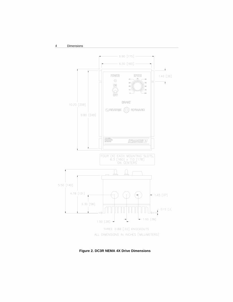
Figure 2. DC3R NEMA 4X Drive Dimensions

5Dimensions
Figure 3. DC3R Heat Sink Dimensions
ALL DIMENSIONS IN INCHES [MILLIMETERS]
6
Installation
Wiring
ATTENTION: The control circuit is at line potential when the drive isenergized. Use a non-metallic screwdriver when making adjustments tothe circuit board potentiometers. Exercise extreme caution as hazardousvoltage exists. Failure to observe these precautions could result insevere bodily injury of loss of life.
ATTENTION: Do not disconnect any of the motor leads from thedrive unless power is removed or the drive is disabled. Opening anyone motor lead may destroy the drive, or cause severe injury or loss oflife.
ATTENTION: Installation of a master power switch in the input line isrequired. This is to disconnect power from the motor. The user isresponsible for assuring safe conditions for operating personnel byproviding suitable guards, audio or visual alarms, or other devices.Failure to observe these precautions could result in bodily injury.
ATTENTION: To provide the motor with overload protection, local,national, and international codes (e.g.,NEC/CEC) require that a motorthermostat, internal to the motor, be installed or an electronic thermalmotor overload relay, sized to protect the motor, be installed betweenthe motor and the drives output terminals.
m
ATTENTION: Only qualified technical personnel, familiar with theconstruction and operation of this equipment and the hazards involved,should install, adjust, operate and/or service this equipment. Read andunderstand this instruction manual in its entirety before proceeding.Failure to observe this precaution could result in severe bodily injury orloss of life.
ATTENTION: This equipment is at line voltage when AC power isconnected. Disconnect and lockout all ungrounded conductors of theAC power line before working on the unit. Failure to observe thisprecaution could result in severe bodily injury or loss of life.
ATTENTION: The user is responsible for conforming with allapplicable local and national codes. Failure to observe this precautioncould result in severe bodily injury or loss of life.
m

7Installation
As a general rule, Reliance Electric recommends shielding of allconductors if:
• wire lengths exceed 4 inches and power and logic leads must be bundledtogether*; or• radiated and/or conducted noise must be minimized due to sconcernsabout immunity or general compliance (CE, FCC, etc.)
It may be necessary to earth ground the shielded cable. If noise isproduced by devices other than the drive, ground the shield at the driveend. If noise is generated by a device on the drive, ground the shield at theend away from the drive. Do not ground both ends of the shield.
If the drive continues to pick up noise after grounding the shield, it may benecessary to add AC line filtering devices, or to mount the drive in a lessnoisy environment.
*Reliance Electric considers this an unfavorable condition and does notrecommend bundling of power and logic leads for any length.
ATTENTION: If it is not practical to shield power conductors,Reliance Electric recommends shielding all logic-level leads. Ifshielding is not practical, use twisted pair control wiring to minimizeinduced electrical noise.
ATTENTION: Under no circumstances should unshielded power andlogic leads be bundled together. Induced voltage can causeunpredictable behavior any electronic device, including motor controls.
m
Shielding guidelines
Use 18-24 AWG wire for speed adjust potentiometer wiring. Use 14–16AWG wire for AC line (L1, L2) and motor (A1 and A2) wiring.

8 Installation
Input isolation transformers might be needed to help eliminate thefollowing:
· Damaging line voltage transients from reaching the drive.
· Line noise from the drive back to the incoming power source.
· Damaging currents that could develop if a point inside the drive becomes grounded.
Observe the following guidelines when installing an isolation transformer:
· A power disconnecting device must be installed between the power lineand primary of the transformer.
· If the power disconnecting device is a circuit breaker, the circuit breakertrip rating must be coordinated with the in-rush current (10-12 times fullload current) of the transformer.
Optional isolation transformer
ATTENTION: Distribution system capacity above the maximumrecommended system KVA requires the use of an isolation transformer,a line reactor, or other means of adding similar impedance to the drivepower input. Failure to observe these precautions could result indamage to, or destruction of, the equipment.
m

9Installation
Protect the drive from dirt, moisture, and accidental contact. Providesufficient room for access to the terminal block and calibration trimpots.
Mount the drive away from other heat sources. Operate the drive withinthe specified ambient operating temperature range.
Prevent loose connections by avoiding excessive vibration of the drive.
Mount the drive with its board in either a horizontal or vertical plane. Six0.188 inch (4.8 mm) wide slots in the chassis accept #8 pan head screws.Fasten either the large base or the narrow flange of the chassis to thesubplate.
The chassis must be earth grounded for noise suppression. To ground thechassis, connect earth ground to the GND terminal on terminal block 501(TB501).
Mounting chassis drives
ATTENTION: This drive contains ESD (Electric Static Discharge)sensitive parts and assemblies. Static control precautions are requiredwhen installing, testing, servicing, or repairing this assembly. Failureto observe these precautions could result in damage to, or destructionof, the equipment.
m

10 Installation
Mounting enclosed drives
NEMA 4X enclosed drives come with three 0.88 inch (22 mm) conduitknockout holes at the bottom of the enclosure. The units may be verticallywall mounted using the four 0.25 inch (6 mm) slotted holes on the attachedheat sink. For motor loads less than 5 ADC, the drive may be benchmounted horizontally, or operated without mounting.
1. Install the mounting screws.
2. For access to the terminal strip, turn the slotted screw on the front covercounterclockwise until it is free from the enclosure. The right side of thecover is hinged to the enclosure. Lift or pull the slotted screw to openthe enclosure.
3. Carefully remove the conduit knockouts by tapping them into theenclosure and twisting them off with pliers.
4. Install conduit hardware through the 0.88 inch (22 mm) conduit holes.Connect external wiring to the terminal block.
5. Grasp the slotted screw and tilt the front cover back into place. Avoidpinching any wires between the front cover and the enclosure.
6. Turn the slotted screw clockwise until tight to secure the front cover.
7. Set the POWER switch to the “0” or OFF position before applying theAC line voltage.
Heat sinking
Chassis DC3R models require an additional heat sink when the continuousarmature current is above 7 ADC. Use Reliance® part number DC3R-HS-00. All enclosed drives have sufficient heat sinking in theirbasic configurations. Use a thermally conductive heat sink compound(such as Dow Corning® 340 Heat Sink compound) between the drivechassis and the heat sink surface for optimum heat transfer.

11Installation
Cage-clamp terminal block
Connections to the DC3R drive are made to a cage-clamp terminal block(Figure 4). To insert a wire into the terminal block, press down on thelever arm using a small screwdriver. Insert stripped wire into the largeopening in front of the terminal block. Release the lever arm to clamp thewire.
Lever Arm
Figure 4. Cage-Clamp Terminal Block
Field output
The field output is for shunt wound motors only. Do not make anyconnections to F1 and F2 when using a permanent magnet motor.
Use 18 AWG wire to connect the field output to a shunt wound motor.Table 1 lists the field output connections.
Table 1. Field Output ConnectionsLine Voltage Approximate Connect Motor (VAC) Field Voltage (VDC) Field To115 50 F1 and L1115 100 F1 and F2230 100 F1 and L1230 200 F1 and F2

12 Installation
Tachogenerator feedback
ATTENTION: Applying the incorrect polarity to the tachogeneratorcan cause an overspeed condition. Make sure the positive (+) wire isconnected to terminal T1 and the negative (-) wire is connect toterminal T2 when the motor is running in the forward direction. Failureto observe this precaution could result in bodily injury.
m
Using tachogenerator feedback improves speed regulation fromapproximately 1% of motor base speed to approximately 0.1% of motorbase speed. Use tachogenerators rated from 7 VDC per 1000 RPM to 50 VDC per 1000 RPM.
Connect the tachogenerator to terminals T1 and T2 of terminal block 502(TB502). The polarity is + for T1 and – for T2 when the motor running inthe forward direction. The polarity is reversed when the motor is runningin the reverse direction.

13
Chassis drive connections
Installation
Connections
Figure 5. Chassis Drive Connections
NOTE: TERMINAL 1 IS THE HOTCONNECTION. TERMINALS 2 AND3 ARE NEUTRAL CONNECTIONS.

14 Installation
Figure 6. Enclosed Drive Connections
Enclosed drive connections
NOTE: TERMINAL 1 IS THE HOTCONNECTION. TERMINALS 2 AND3 ARE NEUTRAL CONNECTIONS.

15
ATTENTION: Because the reference potentiometer is connectedthrough the regulator to the armature power circuit, its terminals are atline potential. Use a potentiometer that has a insulating shaft to insulatethe operator knob from this power circuit and that is capable ofwithstanding Hi-pot tests at 2000 Volts DC for one minute. Failure toobserve this precaution could result in severe bodily injury or loss oflife.
ATTENTION: Be sure that the potentiometer tabs do not make contactwith the potentiometer enclosure. Grounding the input will causedamage to the drive.
Installation
Speed adjust potentiometer installation
Figure 7. Speed Adjust Potentiometer
On chassis drives, install the circular insulating disk between the panel andthe 10 Kohm speed adjust potentiometer. Mount the speed adjustpotentiometer through a 0.38 in. (0.96 cm) hole with the hardwareprovided (see Figure 7). Twist the speed adjust potentiometer wire to avoidpicking up unwanted electrical noise. If potentiometer leads are longerthan 18 in. (46 cm), use shielded cable. Speed adjust potentiometers areinstalled on all enclosed drives.
m

16 Installation
Speed adjust potentiometer connections
Figure 8. Speed Adjust Potentiometer Connections for (a)Unidirectional Operation, and (b) Bidirectional Operation
(a) (b)
The motor can operate in one direction (unidirectional) or in two directions(bidirectional) depending on how the speed adjust potentiometer isconnected to the drive.
Connect the speed adjust potentiometer as shown in Figure 8(a) for speedcontrol in one direction.
Connect the speed adjust potentiometer as shown in Figure 8(b) for speedcontrol in two directions. The motor does not rotate when the wiper is inthe center position. Turning the wiper CW from the center position causesthe motor to rotate in one direction, while turning the wiper CCW from thecenter position causes the motor to rotate in the opposite direction.
Refer to the Application Notes section for additional speed adjustpotentiometer connections.
ATTENTION: At very low input levels, noise or drift could causeanalog input polarity to change. This could cause the motor to rotate inthe opposite direction. Proper precautions should be taken as this couldresult in damage to, or destruction of, the equipment.
m

17
ATTENTION: The equipment is at line voltage when AC power isconnected. Disconnect and lockout all ungrounded conductors of theAC power line. Failure to observe this precaution could result in severebodily injury or loss of life.
Installation
+15 and –15 terminals
DC3R drives can supply a regulated +15 and –15 VDC signal (eachsourcing 25 mA maximum) to isolated, external devices. These voltagesupply terminals are located on terminal block 502 (TB502).
IMPORTANT: Do not short +15 and –15 terminals for any reason!Shorting these terminals may damage the drive.
m
ATTENTION: Most code requires that upstream branch protection beprovided to protect input power wiring. Failure to observe thisprecaution could result in severe bodily injury or loss of life.
m
DC3R drives require fuses for protection. Use fast acting fuses rated for250 VAC or higher, and approximately 150% of the maximum armaturecurrent. Fuse both L1 and L2 when the line voltage is 230 VAC.
Table 2 lists the recommended line fuse sizes.
Table 2. Fuse Chart90 VDC Motor 180 VDC Max. DC Armature AC Line Fuse
Horsepower Horsepower Current (amps) Size (amps)1/20 1/10 0.5 31/15 1/8 0.8 31/8 1/4 1.5 51/6 1/3 1.7 51/4 1/2 2.6 81/3 3/4 3.5 81/2 1 5.0 103/4 1 1/2 7.6 151 2 10 20
Install the required, user-supplied branch circuit protection fuses accordingto the applicable local, national, and international codes (e.g., NEC/CEQ.The fuses must be installed in the line before the drive input terminals.
Line Fusing for DC3R Drives

18
Voltage follower
The drive may be wired to follow a floating (isolated) 0 to ±10V signalthat is isolated from earth ground instead of using a speed adjustpotentiometer. Connect the signal input to S2, and the signal common toS0 (see Figure 9).
Installation
Figure 9. Voltage Follower Connections

19
ATTENTION: Only qualified technical personnel, familiar with theconstruction and operation of this equipment and the hazards involved,should install, adjust, operate and/or service this equipment. Read andunderstand this instruction manual in its entirety before proceeding.Failure to observe this precaution could result in severe bodily injury orloss of life.
ATTENTION: This equipment is at line voltage when AC power isconnected. Disconnect and lockout all ungrounded conductors of theAC power line before working on the unit. Failure to observe thisprecaution could result in severe bodily injury or loss of life.
ATTENTION: The user is responsible for conforming with allapplicable local and national codes. Failure to observe this precautioncould result in severe bodily injury or loss of life.
mOperation

20
1. Check connections before applying AC line voltage to the drive.
2. Check that no conductive material is present on the printed circuitboard.
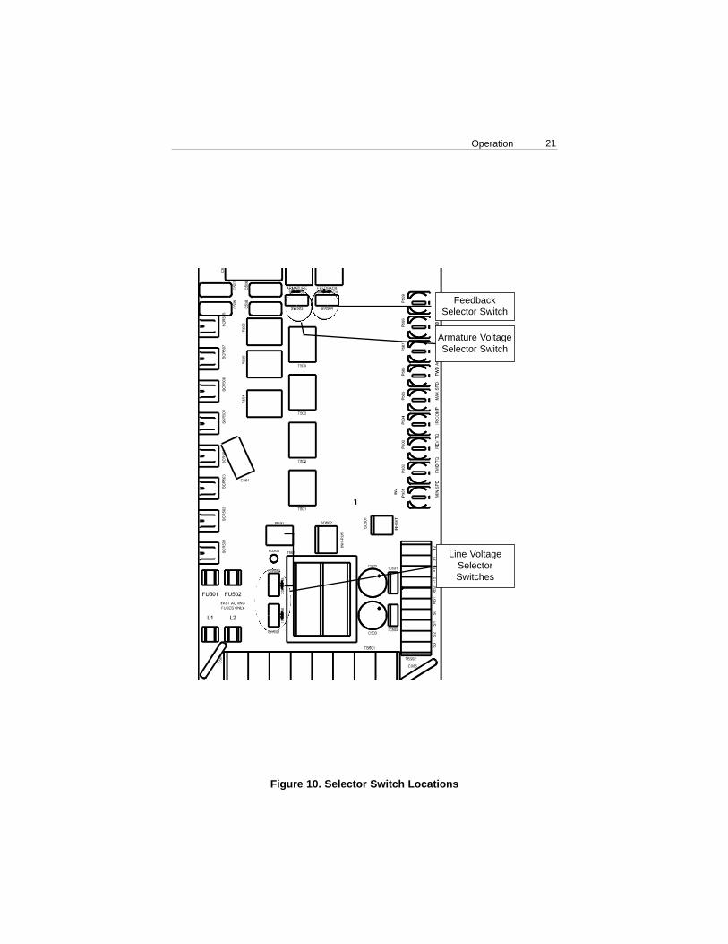
3. Verify that all selector switches are set correctly (see the followingsection for selector switch settings). See Figure 10 for all switchlocations.
Selector switch settings
Operation
Before applying power
ATTENTION: Change voltage switch settings only when the drive isdisconnected from AC line voltage. Make sure both switches are set totheir correct position. If the switches are improperly set to a lowervoltage position, the motor will not run at full voltage and may causedamage to the transformer. If the switches are improperly set to ahigher voltage position, the motor will overspeed, which may causemotor damage or severe bodily injury or loss of life.
m
ATTENTION: Change slide switch settings only when the drive isdisconnected from the AC line voltage. Make sure both line voltageand motor switches are set to their correct position. If the switches areimproperly set to a lower voltage position, the motor will not run at fullvoltage and may cause transformer damage. If the switches areimproperly set to a higher voltage position, the motor will overspeed,which may cause motor damage or severe bodily injury or loss of life.
m
1. Set the line voltage selector switches (SW501 and SW502) to 115 ifusing 115 VAC line voltage, or to 230 if using 230 VAC line voltage.
2. Set the armature voltage selector switch (SW503) to 90 if using a 90VDC motor, or to 180 if using a 180 VDC motor.
3. Set the feedback selector switch (SW504) to TACH if using atachogenerator; otherwise set it to ARM for armature feedback.
IMPORTANT: You may be required to derate a 90 VDC motor when 230 VAC is applied to the drive. Contact the factory for details.
21Operation
Line VoltageSelectorSwitches
Armature VoltageSelector Switch
FeedbackSelector Switch
Figure 10. Selector Switch Locations

22 Operation
Startup
Chassis drive
1. Set the speed adjust potentiometer for zero speed.2. Apply AC line voltage.3. Slowly advance the speed adjust potentiometer clockwise (CW). The
motor slowly accelerates as the potentiometer is turned CW. Continueuntil the desired speed is reached.
4. Remove AC line voltage from the drive to coast the motor to a stop.
Enclosed drive
1. Set the FORWARD/BRAKE/REVERSE switch to the BRAKE position.2. Set the speed adjust potentiometer to “0” (full CCW).3. Apply AC line voltage.4. Set the POWER switch to the ON position.5. Set the FORWARD/BRAKE/REVERSE switch to the desired direction
of rotation.7. Slowly advance the speed adjust potentiometer clockwise (CW). The
motor slowly accelerates as the potentiometer is turned CW. Continueuntil the desired speed is reached.
8. To brake the motor, set the FORWARD/BRAKE/REVERSE switch tothe BRAKE position. To coast the motor to a stop, set the POWERswitch to the OFF position.
9. To reverse direction:a. Set the FORWARD/BRAKE/REVERSE switch to the BRAKE
position.b. After the motor comes to a complete stop, set the
FORWARD/BRAKE/REVERSE switch to the desired direction ofrotation.
10. Set the POWER switch to OFF to remove power from the drive.

23Operation
Line starting and line stopping
Line starting and line stopping (applying and removing AC line voltage) isrecommended for infrequent starting and stopping of a drive only. WhenAC line voltage is applied to the drive, the motor accelerates to the speedset by the speed adjust potentiometer. When AC line voltage is removed,the motor coasts to a stop.
Automatic restart upon power restoration
All drives automatically run to set speed when power is applied. Wiring alatching relay into the AC line is one way to prevent automatic restartingfollowing a power outage.
Starting and Stopping Methods
ATTENTION: For frequent starts and stops, use regenerativedeceleration (shorting RB1 and RB2), regenerative braking (shortingINHIBIT terminals to each other), coasting to a stop (shortingINHIBIT–RUN terminals 1 and 2), or decelerating to minimum speed(shorting S2 to S0). Do not use any of these methods for emergencystopping. They may not stop a drive that is malfunctioning. RemovingAC line power (both L1 and L2) is the only acceptable method foremergency stopping.
ATTENTION: Starting and stopping with the inhibit terminal pins doesnot disconnect AC power in the stop position. A hardwired AC powerdisconnection switch must be mounted in close proximity to theoperator’s start/stop controls. This is required, as the DC3 drive doesnot have an armature loop contactor. A single fault like a power deviceshort may cause motor rotation when in the stop mode. The user isresponsible for assuring safe conditions for operating personnel byproviding suitable guards, audio or visual alarms, or other devices.Failure to observe these precautions could result in bodily injury.
m
24 Operation
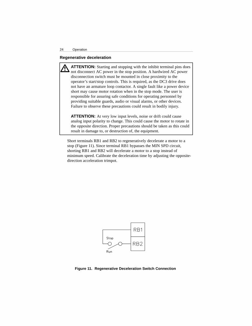
Figure 11. Regenerative Deceleration Switch Connection
Regenerative deceleration
Short terminals RB1 and RB2 to regeneratively decelerate a motor to astop (Figure 11). Since terminal RB1 bypasses the MIN SPD circuit,shorting RB1 and RB2 will decelerate a motor to a stop instead ofminimum speed. Calibrate the deceleration time by adjusting the opposite-direction acceleration trimpot.
ATTENTION: Starting and stopping with the inhibit terminal pins doesnot disconnect AC power in the stop position. A hardwired AC powerdisconnection switch must be mounted in close proximity to theoperator’s start/stop controls. This is required, as the DC3 drive doesnot have an armature loop contactor. A single fault like a power deviceshort may cause motor rotation when in the stop mode. The user isresponsible for assuring safe conditions for operating personnel byproviding suitable guards, audio or visual alarms, or other devices.Failure to observe these precautions could result in bodily injury.
ATTENTION: At very low input levels, noise or drift could causeanalog input polarity to change. This could cause the motor to rotate inthe opposite direction. Proper precautions should be taken as this couldresult in damage to, or destruction of, the equipment.
m

25Operation
INHIBIT TERMINALS
Figure 12. Inhibit Terminals
Regenerative braking using the INHIBIT circuit
ATTENTION: Starting and stopping with the inhibit terminal pins doesnot disconnect AC power in the stop position. A hardwired AC powerdisconnection switch must be mounted in close proximity to theoperator’s start/stop controls. This is required, as the DC3 drive doesnot have an armature loop contactor. A single fault like a power deviceshort may cause motor rotation when in the stop mode. The user isresponsible for assuring safe conditions for operating personnel byproviding suitable guards, audio or visual alarms, or other devices.Failure to observe these precautions could result in bodily injury.
m
Short the INHIBIT terminals to regeneratively brake the motor (seeFigure 12 for INHIBIT terminal location). Reopening the INHIBITterminals causes the motor to accelerate to set speed.
The INHIBIT terminals bypass both the MIN SPD circuit and thedeceleration circuit. This causes the motor to stop rapidly when theINHIBIT terminals are shorted. Braking torque is determined by theopposite-direction torque setting.
Twist inhibit wires and separate them from other power-carrying wires orsources of electrical noise. Use shielded cable if the inhibit wires arelonger than 18 in. (46 cm). If shielded cable is used, ground only one endof the shield to earth ground. Do not ground both ends of the shield.

26 Operation
Figure 13. INHIBIT-RUN Terminals
INHIBIT-RUNTERMINALS
Coast to a stop using the INHIBIT circuit
ATTENTION: Starting and stopping with the inhibit terminal pins doesnot disconnect AC power in the stop position. A hardwired AC powerdisconnection switch must be mounted in close proximity to theoperator’s start/stop controls. This is required, as the DC3 drive doesnot have an armature loop contactor. A single fault like a power deviceshort may cause motor rotation when in the stop mode. The user isresponsible for assuring safe conditions for operating personnel byproviding suitable guards, audio or visual alarms, or other devices.Failure to observe these precautions could result in bodily injury.
m
To coast the motor to a stop without removing power to the drive, jumperINHIBIT–RUN terminals 1 and 2 (Figure 13). To restart the motor, jumperINHIBIT–RUN terminals 2 and 3. A single-throw, double-pole switch maybe used as a COAST/RUN switch.
IMPORTANT: Each drive is assembled with INHIBIT–RUN terminals 2and 3 jumpered. These terminals must be connected for the motor to run.
Certain Reliance Electric drives (regenerative and non-regenerative) coastto minimum speed when the inhibit terminals are shorted to each other. IR COMP and CURRENT LIMIT (FWD TQ and REV TQ on regenerativedrives) are still active while the drive is in the inhibit mode.
Frequent regenerative deceleration, regenerative braking, coasting to astop, or decelerating to minimum speed produces high torque. This maycause damage to motors, especially gearmotors that are not properly sizedfor the application.

27
The circuit shown in Figure 14 may be used to decelerate a motor to aminimum speed. Closing the switch between S2 and S0 decelerates themotor from set speed to a minimum speed determined by the MIN SPDtrimpot setting. If the MIN SPD trimpot is set full CCW, the motordecelerates to zero speed when the switch between S2 and S0 is closed.The DECEL trimpot setting determines the rate at which the drivedecelerates. Set the switch to the RUN position to accelerate the motor toset speed at a rate determined by the ACCEL trimpot setting.
Operation
Decelerate to minimum speed
Figure 14. Run/Decelerate to Minimum Speed Switch(shown with bidirectional speed adjust potentiometer connection)
ATTENTION: Starting and stopping with the inhibit terminal pins doesnot disconnect AC power in the stop position. A hardwired AC powerdisconnection switch must be mounted in close proximity to theoperator’s start/stop controls. This is required, as the DC3 drive doesnot have an armature loop contactor. A single fault like a power deviceshort may cause motor rotation when in the stop mode. The user isresponsible for assuring safe conditions for operating personnel byproviding suitable guards, audio or visual alarms, or other devices.Failure to observe these precautions could result in bodily injury.
m
28
Figure 15. Calibration Trimpot Layout
Each drive is factory calibrated to its maximum horsepower rating.Readjust the calibration trimpot settings to accommodate lowerhorsepower motors.
All adjustments increase with CW rotation, and decrease with CCWrotation. Use a non-metallic screwdriver for calibration. Each trimpot isidentified on the printed circuit board.
ATTENTION: The following adjustments are made with power on.Exercise extreme caution as hazardous voltage exists. Failure toobserve this precaution could result in severe bodily injury or loss oflife.
ATTENTION: The control circuit is at line potential when the drive isenergized. Use a non-metallic screwdriver when making adjustments tothe circuit board potentiometers. Exercise extreme caution ashazardous voltage exists. Failure to observe these precautions couldresult in severe bodily injury or loss of life.
mCalibration
FORWARDTORQUE
IR COMP FORWARDACCELERATION
REVERSEACCELERATION
REVERSETORQUE
MAXIMUMSPEED
TACH
DEADBAND
MINIMUMSPEED

29Calibration
ATTENTION: The DC3 Drive is intended to operate at apredetermined minimum speed. If the application requires zero speedoperation, the user is responsible for assuring safe conditions foroperating personnel by providing suitable guards, audio or visualalarms, or other devices. Failure to observe these precautions couldresult in bodily injury.
ATTENTION: At very low input levels, noise or drift could causeanalog input polarity to change. This could cause the motor to rotate inthe opposite direction. Proper precautions should be taken as this could
result in damage to, or destruction of, the equipment.
m
MIN SPD
The MIN SPD setting determines the minimum speed when the speedadjust potentiometer is turned full CCW. It is factory set to zero speed.
IMPORTANT: The minimum speed feature applies only when the driveis operating in unidirectional mode.
To calibrate, set the speed adjust potentiometer full CCW. Adjust the MINSPD trimpot until the motor turns at the desired minimum speed.
MAX SPD
The MAX SPD setting determines the maximum motor speed when thespeed adjust potentiometer is turned full CW. It is factory set for maximumrated motor speed.
To calibrate, set the speed adjust potentiometer full CW. Adjust the MAXSPD trimpot until the motor turns at the desired maximum speed.

FWD TQ
REV TQ
30 Calibration
The FWD TQ setting determines the maximum torque for accelerating anddriving the motor in the forward direction. It also sets the maximum torquefor decelerating the motor in the reverse direction. FWD TQ is factory setat 120% of rated motor current.
If the time it takes to accelerate a load is too long due to the forwardtorque setting, increase the forward torque setting to 130% of rated motorcurrent. The decision to change the forward torque setting must be madeafter considering the gearbox and drivetrain ratings, duty cycle, and motorcharacteristics. See Figure 16 for typical FWD TQ settings.
ATTENTION: Although FWD TQ is set to exceed the motornameplate current rating, continuous operation beyond that rating maydamage the motor.
m
The REV TQ setting determines the maximum torque for accelerating anddriving the motor in the reverse direction. It also sets the maximum torquefor decelerating in the forward direction. REV TQ is factory set at 120%of rated motor current.
If the time it takes to accelerate a load is too long due to the reverse torquesetting, increase the reverse torque setting to 130% of rated motor current.The decision to change the reverse torque setting must be made afterconsidering the gearbox and drivetrain ratings, duty cycle, and motorcharacteristics. See Figure 16 for typical REV TQ settings.
IR COMP
The IR COMP setting determines the degree to which motor speed is heldconstant as the motor load changes. It is factory set for optimum motorregulation.
ATTENTION: Although REV TQ is set to exceed the motornameplate current rating, continuous operation beyond that rating maydamage the motor.
m

31Calibration
Recalibrate the IR COMP setting when using a lower horsepower motor.See Figure 19 for typical IR COMP settings, or recalibrate using thefollowing procedure:
If the motor does not maintain set speed as the load changes, graduallyrotate the IR COMP trimpot CW. If the motor oscillates(overcompensation), the IR COMP trimpot may be set too high (CW).Turn the IR COMP trimpot CCW until the drive stabilizes.
FWD ACC
The FWD ACC setting determines the time the motor takes to ramp toeither a higher speed in the forward direction or a lower speed in thereverse direction, within the limits of available torque. The FWD ACCsetting is factory set for its fastest forward acceleration time.
Turn the FWD ACC trimpot CW to increase the forward acceleration time,and CCW to decrease the forward acceleration time.
REV ACC
The REV ACC setting determines the time the motor takes to ramp toeither a higher speed in the reverse direction or a lower speed in theforward direction, within the limits of available torque. The REV ACCsetting is factory set for its fastest reverse acceleration time.
Turn the REV ACC trimpot CW to increase the reverse acceleration time,and CCW to decrease the reverse acceleration time.
DB (Range)
The deadband trimmer potentiometer determines the time that will elapsebetween the application of current in one direction before current isapplied in the opposite direction.
The deadband trimmer potentiometer affects the resistance that a motor hasto changes in shaft position at zero speed. It does this by applying ACvoltage to the motor armature.
Deadband is factory calibrated to approximately the 3 o’clock position for60 Hz AC line operation. Recalibrate the deadband to the 9 o’clockposition for 50 Hz AC line operation. See Figure 17 for recommendeddeadband settings.

32
Calibrate the TACH setting only when a tachogenerator is used. TheTACH setting, like the IR COMP setting, determines the degree to whichmotor speed is held constant as the motor load changes.
To calibrate the TACH trimpot:1. Disconnect power from drive.2. Connect the tachogenerator to T1 and T2. The polarity is + for T1 and
– for T2 when the motor running in the forward direction.3. Set switch 504 (SW504) to ARM for armature feedback.4. Apply power to drive.5. Set the speed adjust potentiometer full CW. Measure the armature
voltage across A1 and A2 using a voltmeter.6. Set the speed adjust potentiometer to 0 (zero speed).7. Disconnect power from drive.8. Set SW504 to TACH for tachogenerator feedback.9. Set the IR COMP trimpot full CCW.10. Set the TACH trimpot full CW.11. Apply power to drive.12. Set the speed adjust potentiometer full CW.13. Adjust the TACH trimpot until the armature voltage is the same value
as the voltage measured in step 5.
Check that the tachogenerator is properly calibrated. The motor should runat the same set speed when SW504 is set to either armature ortachogenerator feedback.
Calibration
ATTENTION: Applying the incorrect polarity to the tachogeneratorcan cause an overspeed condition. Make sure the positive (+) wire isconnected to terminal T1 and the negative (-) wire is connect toterminal T2 when the motor is running in the forward direction. Failureto observe this precaution could result in bodily injury.
mTACH

33Calibration
Figure 16. Typical FWD TQ, REV TQ, and IR COMP Settings(actual settings may vary with each application)
Figure 17. Deadband Settings

34
Application Notes
FWD-REV switch
Use a single-pole, two-position switch with a single speed adjustpotentiometer to plug reverse the motor (Figure 18). The MIN SPD settingis in effect for either direction.
Figure 18. Forward-Reverse Switch
ATTENTION: The equipment is at line voltage when AC power isconnected. Disconnect and lockout all ungrounded conductors of theAC power line. Failure to observe this precaution could result in severebodily injury or loss of life.
m
ATTENTION: At very low input levels, noise or drift could causeanalog input polarity to change. This could cause the motor to rotate inthe opposite direction. Proper precautions should be taken as this couldresult in damage to, or destruction of, the equipment.
mOptional speed adjust potentiometer connections

35
Use a single-pole, three-position switch with a single speed adjustpotentiometer to stop a motor between reversals (Figure 19). Set the switchto the center position to decelerate the motor to a stop.
Application Notes
FWD-STOP-REV switch
Figure 19. Forward-Stop-Reverse Switch
ATTENTION: Starting and stopping with the inhibit terminal pinsdoes not disconnect AC power in the stop position. A hardwired ACpower disconnection switch must be mounted in close proximity to theoperator’s start/stop controls. This is required, as the DC3 drive doesnot have an armature loop contactor. A single fault like a power deviceshort may cause motor rotation when in the stop mode. The user isresponsible for assuring safe conditions for operating personnel byproviding suitable guards, audio or visual alarms, or other devices.Failure to observe these precautions could result in bodily injury.
m
36 Application Notes
Independent adjustable speeds
Connect two speed adjust potentiometers with a single-pole two-positionswitch to select between two independent speeds shown in the forwarddirection ( Figure 20). The speed adjust potentiometers can be mounted attwo separate operating stations.
Figure 20. Independent Adjustable Speeds (Forward Direction)

37Application Notes
Independent forward and reverse speeds
Figure 21. Independent Forward and Reverse Speeds
ATTENTION: At very low input levels, noise or drift could causeanalog input polarity to change. This could cause the motor to rotate inthe opposite direction. Proper precautions should be taken as this couldresult in damage to, or destruction of, the equipment.
m
Connect two speed adjust potentiometers as shown in Figure 21 to select between independent forward and reverse speeds.

38 Application Notes
Independent Forward and Reverse Speeds with a Forward-Stop-Reverse Switch
Figure 22. Independent Forward and Reverse Speeds with aForward-Stop-Reverse Switch
ATTENTION: Starting and stopping with the inhibit terminal pinsdoes not disconnect AC power in the stop position. A hardwired ACpower disconnection switch must be mounted in close proximity to theoperator’s start/stop controls. This is required, as the DC3 drive doesnot have an armature loop contactor. A single fault like a power deviceshort may cause motor rotation when in the stop mode. The user isresponsible for assuring safe conditions for operating personnel byproviding suitable guards, audio or visual alarms, or other devices.Failure to observe these precautions could result in bodily injury.
m
Use a single-pole, three-position switch to stop the motor when the switchis in the center position ( Figure 22).

39
Troubleshooting
ATTENTION: This equipment is at line voltage when AC power isapplied. Disconnect and lockout all ungrounded conductors of the ACpower line before working on the unit, Failure to observe thisprecaution may result in severe bodily injury or loss of life.
m
Check the following before proceeding:
• The AC line voltage must match the voltage on the drive nameplate. • On dual voltage drives, check that the voltage switches are set to the
correct position.• The deadband (DB) must be set approximately at the
3 o’clock position for 60 Hz AC line frequency or at 9 o’clock for 50 Hz AC line frequency.
• The motor must be rated for the drive’s rated armature (all motors) and field outputs (shunt wound motors only).
• Do not make any connections to F1 and F2 if using a permanent magnetmotor.
• Terminal block connections should be consistent with the connectionsshown in this manual.
• Check that line fuse FU501 (and FU502 for 230 VAC line voltage) isproperly sized and not blown.

40 Troubleshooting
Line fuse blows
1. Disconnect AC line voltage from the drive.2. Check that the motor cable and armature is not shorted or grounded.
a. Armature resistance should measure approximately 1 to 100 ohms,depending on motor horsepower.
b. A resistance reading from the motor frame to either armature sideshould show open when an ohmmeter is used on its high resistancescale.
3. Check that the field circuit is not open.4. A combination of ambient conditions and frequent
high-current spikes (i.e. reversing) causes fuse to “nuisance trip”.Consider using a slow-blow fuse, or over-rating the fuse 120%
Motor pulsates or surges under load
Readjust the IR COMP setting slightly CCW until the motor speed isstabilized.
Line fuse does not blow, but the motor does not run
1. Verify that the speed adjust potentiometer is not set to its zero speedposition.
2. Check the speed adjust potentiometer for continuity.3. Verify that the inhibit pins are not shorted together.4. Check that INHIBIT–RUN terminals 2 and 3 are connected.5. Verify that the drive is receiving AC line voltage.6. Check that the drive is not in current limit. If the drive is in current
limit, verify that the motor is not jammed. It may be necessary toincrease the FWD TQ or REV TQ setting if it is set lower than thecurrent rating of the motor.
7. Check that the speed adjust potentiometer connections to the terminalblock are correct and not open.
Motor runs too fast at the maximum speed setting
1. Check that the MIN SPD and MAX SPD setting is not set too high.2. Check that the field output connections are secure if you are using a
shunt wound motor.

41Troubleshooting
Motor will not reach the desired speed
ATTENTION: The control circuit is at line potential when the drive isenergized. Use a non-metallic screwdriver when making adjustments tothe circuit board potentiometers. Exercise extreme caution ashazardous voltage exists. Failure to observe these precautions couldresult in severe bodily injury of loss of life.
m
1. Check the MAX SPD setting and increase if necessary.2. Check that the IR COMP setting is not set too low.3. Check that the motor is not overloaded.
42 Troubleshooting
Prewired Connections for Enclosed Drive
Figure 23. Prewired Connections to L1, L2(115) and L2(230)
Figure 24. Prewired Speed Adjust Potentiometer Connections for Enclosed Drives

43
Regenerative Drives
Figure 25. Four Quadrant Operation
Most non-regenerative, variable speed, DC drives control current flow to amotor in one direction. The direction of torque is the same direction as themotor rotation. Non-regenerative drives operate in Quadrant 1, and also inQuadrant 3 if the drive is reversible (see Figure 25). Motors must stopbefore reversing direction. Unless dynamic braking is used, non-regenerative drives cannot oppose an overhauling load, and cannotdecelerate a load faster than coasting to a lower speed.
Regenerative drives operate in two additional quadrants: Quadrant 2 andQuadrant 4. In these quadrants, motor torque is in the opposite direction ofmotor rotation.
Regenerative drives can reverse a motor without contactors, switches,brake resistors, and inhibit plugs. They can also control an overhaulingload and decelerate a load faster than it would take to coast to a lowerspeed.

44
CE ComplianceReliance Electric hereby certifies that its DC3 series drives have beenapproved to bear the “CE” mark provided the conditions of approval(listed in Exhibit “A”) have been met by the end user.
The DC3 series has been tested to the following test specifications:EN55011:1991 (emissions), and EN50082-1:1992 (immunity)
Compliance allows Reliance Electric’s DC3 series to bear the CE mark.
The end user, as described herein, falls into one of two categories:
1. The Consumer will deploy a stand-alone unit as an integral, yetexternal, portion of the machine he/she is operating.
2. The Original Equipment Manufacturer (OEM) will implement theproduct as a component of the machine being manufactured.
Exhibit “A”: Line Filters
In addition to EMI/RFI safeguards inherent in the DC3 series’ design,external filtering is required.
Reliance Electric requires the Corcom® filters listed in Table 3. If theexact filter is not available, the specifications are as follows:
L = 1.8 milliHenries.C = 0.01 microFarad (Line to Ground); 1.1 microFarads (Line toLine).Discharge Resistor = 330Kohms.Rated current: 1.4 times maximum DC motor current.Filter type: Balanced 2-section.

45CE Compliance
Table 3. Corcom ® FiltersNameplate Current of
Motor Wired to the Drive Corcom ® Filter Part Number0 to 4 amps 6VV1
4.1 to 13 amps 20VV1
The filters in Table 3 should be wired to the AC line within 0.25 meters ofthe drive. The ground connection from the filter must be wired to solidearth ground (resistance less than 500 ohms); not machine ground. This isvery important!
Armature Filters
If the end-user is using a CE-approved motor, the correct filter from Table3 is all that is necessary to meet the EMC directives listed herein.
If the end-user is not using a CE-approved motor, a Reliance ElectricCEXXRG filter must be deployed on the output. XX is the rated currenton the filter
The CE20RG is a Real-Pole Balanced-Pi 3-pole filter. If the exact filter isnot available, the specifications are as follows:
L & L1 = 2 * (0.8) milliHenries.C & C1 = 2 * (0.1) microFarads @ 400W VDC.Rin = 0.1 ohm; Rout = 1.2 ohm.
Table 4. Armature Filters
Nameplate Current ofMotor Wired to the Drive Reliance® Filter Part Number
0 to 4 amps CE4RG4.1 to 13 amps CE20RG
The filters in Table 2 must be wired to the DC output of the drive, as closeto the drive as possible. The ground connection from the filter must be wired to solid earth ground (resistance less than 500 ohms); not machineground. This is very important!
The end user must use the filtration listed in Exhibit A to comply with CE.The OEM may choose to provide alternative filtering that encompasses theReliance drive and other electronics within the same panel.

The OEM has this liberty because CE is a machinery directive. Whetheror not every component in the OEM’s machinery meets CE, the OEMmust still submit his machine for CE approval. Thus, no component mustnecessarily meet CE within the machine, as long as the OEM takes thenecessary steps to guarantee the machine does meet CE. By the sametoken, even if every component in the OEM’s machine does meet CE, themachine will not necessarily meet CE as a machine.
Using CE-approved wiring practices (like proper shielding) and the filterslisted in Exhibit A guarantee the drive will meet EN55011 (1991 emissionsstandard) and EN50082-1 (1992 immunity standard).
46 CE Compliance


U.S. Drives Technical Support Tel: (1) 262.512.8176, Fax: (1) 262.512.2222, Email: [email protected], Online: www.ab.com/support/abdrives
Publication D2-3453-December 1999 Copyright © 1999 Rockwell Automation, Inc. All Rights Reserved. Printed in USA.