Speed Control and Regenerative Braking of Bidirectional DC ... · Speed Control and Regenerative...
22
1 Speed Control and Regenerative Braking of Bidirectional DC-DC Converter Fed Permanent Magnet DC Motor Bachelor of Technology In Electrical Engineering By Prem Sai Tirkey (111EE0239) Naganaveen Kumar Chiruvolu (111ee0410) Under the supervision of Dr. Susovon Samanta Assistant Professor, NIT Rourkela Department of Electrical Engineering National Institute of Technology, Rourkela (Odisha)
Transcript of Speed Control and Regenerative Braking of Bidirectional DC ... · Speed Control and Regenerative...
1
Speed Control and Regenerative Braking of Bidirectional
DC-DC Converter
Fed Permanent Magnet DC Motor
Bachelor of Technology
In
Electrical Engineering
By
Prem Sai Tirkey (111EE0239)
Naganaveen Kumar Chiruvolu (111ee0410)
Under the supervision of
Dr. Susovon Samanta
Assistant Professor, NIT Rourkela
Department of Electrical Engineering
National Institute of Technology, Rourkela (Odisha)
2
Department of Electrical Engineering
National Institute of Technology, Rourkela
Odisha – 769008, India
__________________________________________________________________________________
Certificate
This to certify that the thesis entitled “Speed Control and Regenerative Braking of Bidirectional
DC-DC Converter Fed Permanent Magnet DC Motor”, submitted to the National Institute of
Technology Rourkela, Odisha by Prem Sai Tirkey (111EE0239) and Naganaveen Kumar
Chiruvolu (111ee0410) for the award of Bachelor of Technology in the Department of
Electrical Engineering is the bonafide record of research work carried by them under my
supervision and guidance.
……………………………………………..
Dr. Susovon Samanta
Department of Electrical Engineering
NIT, Rourkela – 769008 (India)
Place: Rourkela. India
Date:

3
ACKNOWLEDGEMENT
This work is completed at the Department of Electrical Engineering, National Institute of
Technology Rourkela under the supervision of Prof. Susovon Samanta.
We want to express our earnest appreciation to Prof. Susovon Samanta for his direction and
backing all through our work. Without him we will never have the capacity to finish our work
so easily. He was exceptionally patient to hear our issues that we were confronting during the
venture work and discovering the arrangements. We are all that much appreciative to him for
giving his significant time for us. We are acknowledge and quality his regarded direction and
consolation from genesis to the end of the world of undertaking. We express our appreciation
for being comforting and empowering when we were experiencing weight stage.
We want to express sincere gratitude toward Mr. Mahendra Chandra Joshi for issuing us his
important time, perpetual backing and direction all through the undertaking. We thank our
guardians for their consistent backing and every one of those without whom we wouldn't have
the capacity to effectively finish the undertaking.
Finally we want to thank the staff of Electrical designing division for consistent bolster and
giving work environment amid task period.
Prem Sai Tirkey
Naganaveen Kumar Chiruvolu
Electrical Engg. Dept.
4
ABSTRACT
This thesis mainly emphasis on speed control and regenerative braking of PMDC motor fed by
a bidirectional DC-DC converter. The main objective is to increase the efficiency of the motor
and also the power flow in both directions which also further improves efficiency during
regenerative braking mode. Different types of bidirectional DC-DC converters have been
studied. As we all know that during the buck mode operation of converter regenerative braking
occurs which in turn charges the battery whereas in boost mode the battery supplies the required
power to run the motor. So out of all the present bidirectional DC-DC converters we have opted
for half bridge non-isolated bidirectional DC-DC converter because it is cheap, less number of
components and due to its low weight. In order to decrease the switching losses we have
implemented International rectifiers (IR2110), in which the input is a pulse and its outputs are
two pulses complimentary to each other of required period through which MOSFET can be
triggered. So for further reduction in losses we have optimized all the values of inductor,
capacitor by zero voltage techniques so as to achieve the required specifications. All the
parameters discussed in the thesis have been controlled and simulated during both the
operations and are verified with theoretical results.
5
CONTENTS
Chapter-1 INTRODUCTION……………………………………………………………..... (8)
1.1 INTRODUCTION............................................................................................... (8)
1.2 OBJECTIVE………………………………………….………………………… (9)
1.3 MOTIVATION……………………………………….………………………… (9)
1.4 LITERATURE REVIEW…………………………….………………………… (9)
Chapter-2 BIDIRECTIONAL DC-DC CONVERTER………………………………….. (10)
2.1 INTRODUCTION……………………………………………………………. (10)
2.2 CLASSIFICATION OF BIDIRECTIONAL DC-DC CONVERTERS……… (10)
2.3 NON-ISOLATED BIDIRECTIONAL DC-DC CONVERTER
TOPOLOGIES AND its OPERATIONS…………………………………...… (10)
2.3a. HALF BRIDGE CONVERTER…………………………………………….. (12)
2.3b. BUCK-BOOST CONVERTER……………………………………………… (15)
2.3c. BUCK-BOOST CASCADE CONVERTER………………………………… (15)
2.4 SIMULATION………………………………………………………………………... (16)
2.5 SPEED CONTROL OF PMDC MOTOR USING HALF BRIDGE CONVERTER … (19)
Chapter-3
CONCLUSION…………..……………………………………………………………… (20)
Reference……………………….………………………………………………………… (21)

6
LIST OF FIGURES
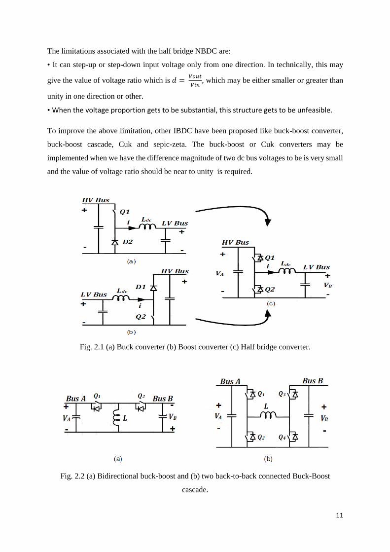
Fig. 2.1 (a) Buck converter (b) Boost converter (c) Half bridge converter.
2.2 (a) Bidirectional buck-boost and (b) two back-to-back connected Buck-Boost cascade
2.3 Half bridge converter
Figure 2.4 (a) Switch Q1 on and Q2 off for DT seconds. (b) Both switch Q1, Q2 off and D2
Gets forward biased for DT to T seconds.
2.5 Inductor Voltage Vs Time in Continuous Conduction.
2.6 Inductor Current Waveform for Continuous Conduction
2.7 Inductor Current at the Boundary of Continuous Conduction
2.8 Buck-boost converter
2.9 Buck-boost cascade converter
2.10 Close loop Buck converter
2.11 Output waveform of close loop buck converter.
2.12 IR2110 internal diagram
2.13 Spice simulation of buck converter
2.14 Out-put waveform
2.15 Half Bridge Non-Isolated Bidirectional DC-DC Converter fed PMDC Motor.
7
LIST OF ABBREVIATIONS
BDC …………………………………………………………... Bidirectional dc-dc converters
DC ………………………………………………………………...……………..Direct current
HEV …………………………………………………..……………….Hybrid electric vehicles
UPS……………………………………………………………Uninterruptible power supplies.
IBDC …………………………………………………………………………… Isolated BDC
AC-link ………………………………………………………………..Alternating current link
PMDC motor ……………………………………………………Permanent magnet DC motor
PID controller ……………………………...…Proportional, integral and derivative controller
ZVRT………………………………….. Zero voltage crossing resonance switching technique
NBDC converter ………………………………………………Non-isolated DC-DC converter
CCM ..............................................................................................continuous conduction mode
DCM ………………………………………………………….discontinuous conduction mode
MOSFET……………………………………….metal–oxide–semiconductor field-effect transistor
8
CHAPTER 1
1.1 INTRODUCTION
Bidirectional dc-dc converters (BDC) [1] [4] have got a ton of consideration as of late and it is
the progressive exploration work because of the expanding need for the systems with the ability
of bidirectional transfer of energy between two dc buses and switched mode DC-DC converters
are one of the least difficult and are simple electronic circuits which can change from one level
of electrical voltage into another by switching activity in both directions. Alongside customary
uses in dc engine drives, new utilizations of BDC is energy stockpiling in renewable energy
frameworks, hybrid electric vehicles (HEV) [2] [7] and UPS. Because of changing nature of
renewable energy resources similar to wind and sun powered, makes them inadmissible for
only source of power and at same time interest for renewable energy systems due consumption
of fossil fuel is expanding over the past decade. An optimal answer for this issue is to utilize
an energy storing system with the renewable energy source for consistent power supply and
keep up a smooth and constant power stream to the load. Thus batteries and super-capacitors
are the most widely recognized and efficient storing devices from low to medium-power range.
A dc-dc converter is constantly needed to permit transfer of energy between input storage
system and whatever remains of system. So, this type of converters should be capable of
bidirectional capacity of power flow with adaptable control in every working mode. In HEV
applications, BDCs links various dc voltage systems and exchange energy between them.
Profoundly effective with lightweight, little less in size in its structure and high unwavering
quality are some essential viewpoint for the BDC utilized as a part of such an application which
can be attained considerably by half bridge BDC. During normal mode in a line UPS, the UPS
yield terminals are joined with the grid and energy is bolstered back to the inverter dc buses
and charge the batteries through a BDC. If there is any break of power supply then the battery
bolsters the inverter dc buses through BDC yet in opposite direction of power flow. The study,
pattern, design of parameters and adjustment of switching converters are the principle
calculates that needs to be weighed in planning a BDC. Numerous control techniques are
utilized for controlling the switch method of DC-DC converters and the straightforwardness
controller structure is dependably sought after most mechanical with superior applications. For
each control technique we have their particular benefits and downsides, and their adequacy is
dictated by the utilization and where it is associated.
BDCs are of two types: non-isolated and isolated [3]. Non-isolated BDCs (NBDC) are simpler
due to absence of transformer than isolated BDCs (IBDC) and their efficiency is also high.
9
However, galvanic isolation is required in many applications and mandated by different
standards. The complexity of IBDCs stems from the fact that an AC-link must be present in
their structure in order to enable power transfer via a magnetically isolating media, i.e. a
transformer. For each outlining of item or simply exploring different algorithms regarding
different calculations and plans, simulation is done before the genuine physical usage. Different
instruments are accessible for developing and reenacting electrical and electronic circuits,
including Math Works Sim Power Systems. It is conceivable to evade this by speaking to the
framework as a mathematical model.
1.2 OBJECTIVE
The main objective of the work is to study the various converter circuit and to plan the
bidirectional dc-dc converter circuit to run the PMDC and subsequently can control it in a
productive way by enhancing the proficiency and diminishing the errors. For speed control of
PMDC motor we used the non-isolated half bridge DC-DC bidirectional converter using PID
controller and complementary switching. Furthermore, utilize the above for the usage and
configuration simulation is done.
1.3 MOTIVATION
In this digitally occupied era, control and automation is major emerging field in electrical
system and we had studied control system in our courses So, the essential target of this work
is to plan, show and mimic the Bidirectional DC-DC converter fed PMDC engine. As per this
target, the technique for selecting a fitting topology of the bidirectional DC-DC converter has
been exhibited.
1.4 LITERATURE REVIEW
The clarification behind enhancing the benefit and to minimize the mistakes we have been
utilized IEEE search paper ([1] to [7]), numerous online inquiry paper and Wikipedia to learn,
outline and examination. We have specified the different research paper [1] to , taking into
account this we planned and contemplated our work. The topological study to drive and to
inspect between them has been displayed. The part, likewise, the essential of the power
equipment and dc- dc converter was overviewed and cleared up. The examination between the
various NBDC on the reason of their execution has been done. The power stage and the ZVRT
exchanging was introduced. A high and low side MOSFET driver IR2110 controlled
bidirectional DC -DC converter was shown.
10
BIDIRECTIONAL DC-DC CONVERTER CHAPTER-2
2.1 INTRODUCTION
The DC-DC Converter shift the input DC voltage and current to a sought yield DC voltage or
current due to this property it is called DC equivalent to AC transformer having continuously
changing turn ratio. DC-DC converters due to application lossless switch give proficient
change of DC voltage starting with one level then onto next. The bi-directional dc-dc converter
in motor drives for HEVs [2] is utilised to control the both motoring and regenerative braking
operations. For motoring operations of motor drive, a dc-dc converter change the motor current
keeping in track to take after the torque reference signal and for the power flow to be reversed,
to recuperate the vehicle kinetic energy from wheel in the battery by method for motor drive
regenerative braking operations. This paper manages with the analysis of bi-directional
converter topologies. Each of them permits stepping the battery voltage level either up or down
with or without changing the polarity.
2.2 CLASSIFICATION OF BIDIRECTIONAL DC-DC CONVERTERS
Depending on their structure BDC are classified [3] as follows:
Non-isolated Bidirectional DC-DC converter (NBDC).
Isolated Bidirectional DC-DC converter (IBDC).
2.3 NON-ISOLATED BIDIRECTIONAL DC-DC CONVERTER TOPOLOGIES AND ITS
OPERATIONS
The basic switch mode DC-DC converters such as buck and boost converters (and their
derivatives) do not have bidirectional power flow capability. This limitation is due to the
presence of unidirectional biased diodes in their structure which prevents reverse current flow.
Generally, a unidirectional dc-dc converter can be turned into a bidirectional converter by
replacing the diodes with a controllable switch in its structure and connecting a diode across
switch in reverse to the power flow.so we have in Fig. 1.1 which shows the half bridge BDC
from a basic buck and boost converter. Similarly bidirectional CUK and Buck-Boost cascade
converter can be derived from their respective unidirectional converter shown in figure 2.2.
11
The limitations associated with the half bridge NBDC are:
• It can step-up or step-down input voltage only from one direction. In technically, this may
give the value of voltage ratio which is 𝑑 = 𝑉𝑜𝑢𝑡
𝑉𝑖𝑛, which may be either smaller or greater than
unity in one direction or other.
• When the voltage proportion gets to be substantial, this structure gets to be unfeasible.
To improve the above limitation, other IBDC have been proposed like buck-boost converter,
buck-boost cascade, Cuk and sepic-zeta. The buck-boost or Cuk converters may be
implemented when we have the difference magnitude of two dc bus voltages to be is very small
and the value of voltage ratio should be near to unity is required.
Fig. 2.1 (a) Buck converter (b) Boost converter (c) Half bridge converter.
Fig. 2.2 (a) Bidirectional buck-boost and (b) two back-to-back connected Buck-Boost
cascade.
12
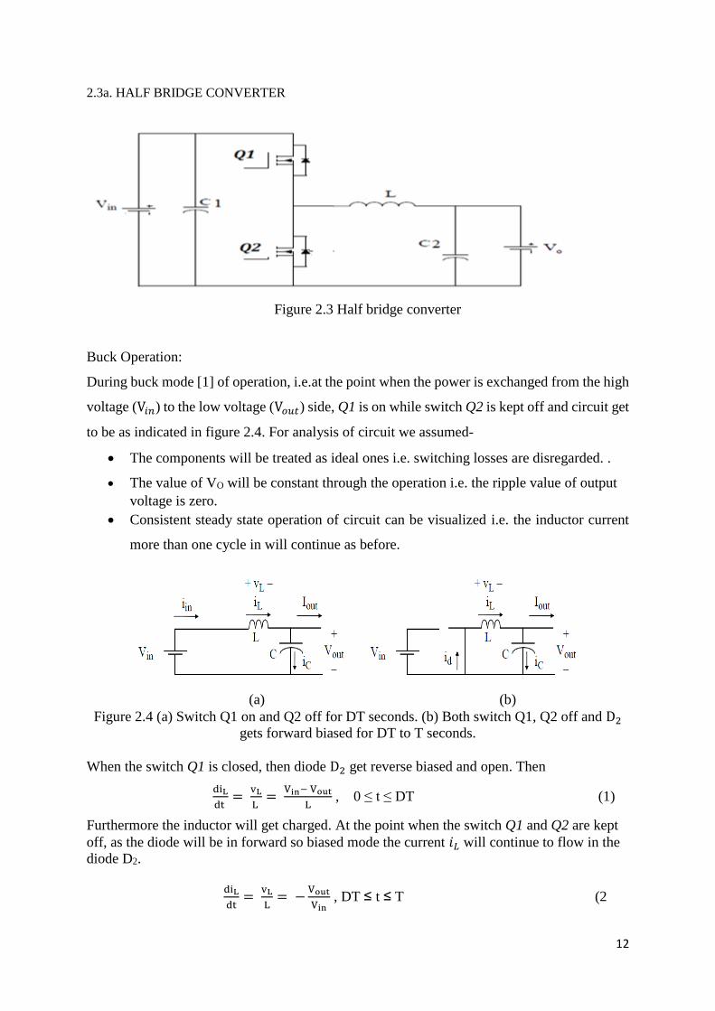
2.3a. HALF BRIDGE CONVERTER
Figure 2.3 Half bridge converter
Buck Operation:
During buck mode [1] of operation, i.e.at the point when the power is exchanged from the high
voltage (V𝑖𝑛) to the low voltage (V𝑜𝑢𝑡) side, Q1 is on while switch Q2 is kept off and circuit get
to be as indicated in figure 2.4. For analysis of circuit we assumed-
The components will be treated as ideal ones i.e. switching losses are disregarded. .
The value of VO will be constant through the operation i.e. the ripple value of output
voltage is zero.
Consistent steady state operation of circuit can be visualized i.e. the inductor current
more than one cycle in will continue as before.
(a) (b)
Figure 2.4 (a) Switch Q1 on and Q2 off for DT seconds. (b) Both switch Q1, Q2 off and D2
gets forward biased for DT to T seconds.
When the switch Q1 is closed, then diode D2 get reverse biased and open. Then
diL
dt =
vL
L =
Vin− Vout
L , 0 ≤ t ≤ DT (1)
Furthermore the inductor will get charged. At the point when the switch Q1 and Q2 are kept
off, as the diode will be in forward so biased mode the current 𝑖𝐿 will continue to flow in the
diode D2.
diL
dt=
vL
L= −
Vout
Vin , DT ≤ t ≤ T (2
13
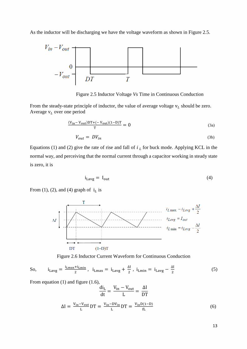
As the inductor will be discharging we have the voltage waveform as shown in Figure 2.5.
Figure 2.5 Inductor Voltage Vs Time in Continuous Conduction
From the steady-state principle of inductor, the value of average voltage v𝐿 should be zero.
Average v𝐿 over one period
(Vin− Vout)DT+(− Vout)(1−D)T
T= 0 (3a)
𝑉𝑜𝑢𝑡 = 𝐷𝑉𝑖𝑛 (3b)
Equations (1) and (2) give the rate of rise and fall of 𝑖 𝐿 for buck mode. Applying KCL in the
normal way, and perceiving that the normal current through a capacitor working in steady state
is zero, it is
iLavg = Iout (4)
From (1), (2), and (4) graph of i𝐿 is
Figure 2.6 Inductor Current Waveform for Continuous Conduction
So, iLavg = iLmax+iLmin
2 , iLmax = iLavg +
∆I
2 , iLmin = iLavg −
∆I
2 (5)
From equation (1) and figure (1.6), diL
dt=
Vin − Vout
L=
∆I
DT
∆I = Vin−Vout
LDT =
Vin−DVin
LDT =
VinD(1−D)
fL (6)
14
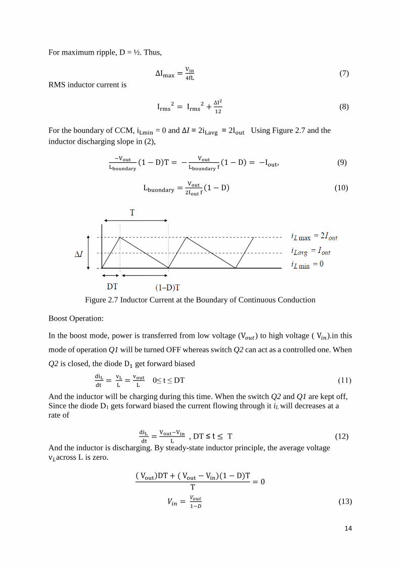
For maximum ripple, D = ½. Thus,
∆Imax =Vin
4fL (7)
RMS inductor current is
Irms2 = Irms
2 +∆I2
12 (8)
For the boundary of CCM, iLmin = 0 and ∆I = 2iLavg = 2Iout Using Figure 2.7 and the
inductor discharging slope in (2),
−Vout
Lboundary(1 − D)T = −
Vout
Lboundary f(1 − D) = −Iout, (9)
Lbuondary =Vout
2Iout f(1 − D) (10)
Figure 2.7 Inductor Current at the Boundary of Continuous Conduction
Boost Operation:
In the boost mode, power is transferred from low voltage (V𝑜𝑢𝑡) to high voltage ( V𝑖𝑛).in this
mode of operation Q1 will be turned OFF whereas switch Q2 can act as a controlled one. When
Q2 is closed, the diode D1 get forward biased
diL
dt =
vL
L =
vout
L 0≤ t ≤ DT (11)
And the inductor will be charging during this time. When the switch Q2 and Q1 are kept off,
Since the diode D1 gets forward biased the current flowing through it iL will decreases at a
rate of
diL
dt=
Vout−Vin
L , DT ≤ t ≤ T (12)
And the inductor is discharging. By steady-state inductor principle, the average voltage
v𝐿across L is zero.
( Vout)DT + ( Vout − Vin)(1 − D)T
T= 0
𝑉𝑖𝑛 = 𝑉𝑜𝑢𝑡
1−𝐷 (13)
15
The value of Inductor in low side results lower value of ripple current which improves the
efficiency. For example we refer to charge and discharge of battery through these values and
accomplish high efficiency and more life time.
The value of capacitor is found to be
C = Iout
4∆Vf (14)
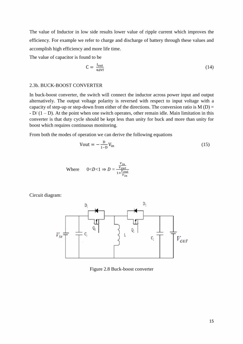
2.3b. BUCK-BOOST CONVERTER
In buck-boost converter, the switch will connect the inductor across power input and output
alternatively. The output voltage polarity is reversed with respect to input voltage with a
capacity of step-up or step-down from either of the directions. The conversion ratio is M (D) =
- D/ (1 – D). At the point when one switch operates, other remain idle. Main limitation in this
converter is that duty cycle should be kept less than unity for buck and more than unity for
boost which requires continuous monitoring.
From both the modes of operation we can derive the following equations
Vout = −D
1−DVin (15)
Where 0<𝐷<1 ⇒ 𝐷 =
𝑉𝑖𝑛𝑉𝑜𝑢𝑡
1+𝑉𝑜𝑢𝑡𝑉𝑖𝑛
Circuit diagram:
Figure 2.8 Buck-boost converter
16
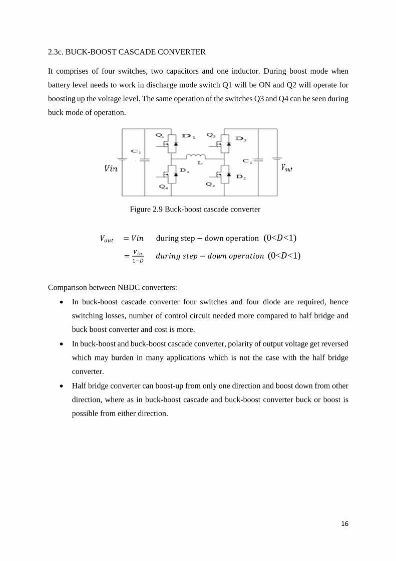
2.3c. BUCK-BOOST CASCADE CONVERTER
It comprises of four switches, two capacitors and one inductor. During boost mode when
battery level needs to work in discharge mode switch Q1 will be ON and Q2 will operate for
boosting up the voltage level. The same operation of the switches Q3 and Q4 can be seen during
buck mode of operation.
Figure 2.9 Buck-boost cascade converter
𝑉𝑜𝑢𝑡 = 𝑉𝑖𝑛 during step − down operation (0<𝐷<1)
=𝑉𝑖𝑛
1−𝐷 𝑑𝑢𝑟𝑖𝑛𝑔 𝑠𝑡𝑒𝑝 − 𝑑𝑜𝑤𝑛 𝑜𝑝𝑒𝑟𝑎𝑡𝑖𝑜𝑛 (0<𝐷<1)
Comparison between NBDC converters:
In buck-boost cascade converter four switches and four diode are required, hence
switching losses, number of control circuit needed more compared to half bridge and
buck boost converter and cost is more.
In buck-boost and buck-boost cascade converter, polarity of output voltage get reversed
which may burden in many applications which is not the case with the half bridge
converter.
Half bridge converter can boost-up from only one direction and boost down from other
direction, where as in buck-boost cascade and buck-boost converter buck or boost is
possible from either direction.

17
2.3 SIMULATION.
Matlab simulation:
Figure 2.10 Close loop Buck converter.
Simulation output:
Figure 2.11 Output waveform of close loop buck converter
18
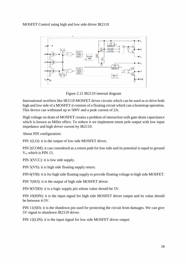
MOSFET Control using high and low side driver IR2110
Figure 2.12 IR2110 internal diagram
International rectifiers like IR2110 MOSFET driver circuits which can be used as to drive both
high and low side of a MOSFET.it consists of a floating circuit which can a bootstrap operation.
This device can withstand up to 500V and a peak current of 2A.
High voltage on drain of MOSFET creates a problem of interaction with gate-drain capacitance
which is known as Miller effect. To reduce it we implement totem pole output with low input
impedance and high driver current by IR2110.
About PIN configuration:
PIN 1(LO): it is the output of low side MOSFET driver.
PIN 2(COM): it can considered as a return path for low side and its potential is equal to ground
Vss which is PIN 13.
PIN 3(VCC): it is low side supply.
PIN 5(VS): it is high side floating supply return.
PIN 6(VB): it is for high side floating supply to provide floating voltage to high side MOSFET.
PIN 7(HO): it is the output of high side MOSFET driver.
PIN 9(VDD): it is a logic supply pin whose value should be 5V.
PIN 10(HIN): it is the input signal for high side MOSFET driver output and its value should
be between 4-5V.
PIN 11(SD): it is the shutdown pin used for protecting the circuit from damages. We can give
5V signal to shutdown IR2110 driver.
PIN 12(LIN): it is the input signal for low side MOSFET driver output.
19
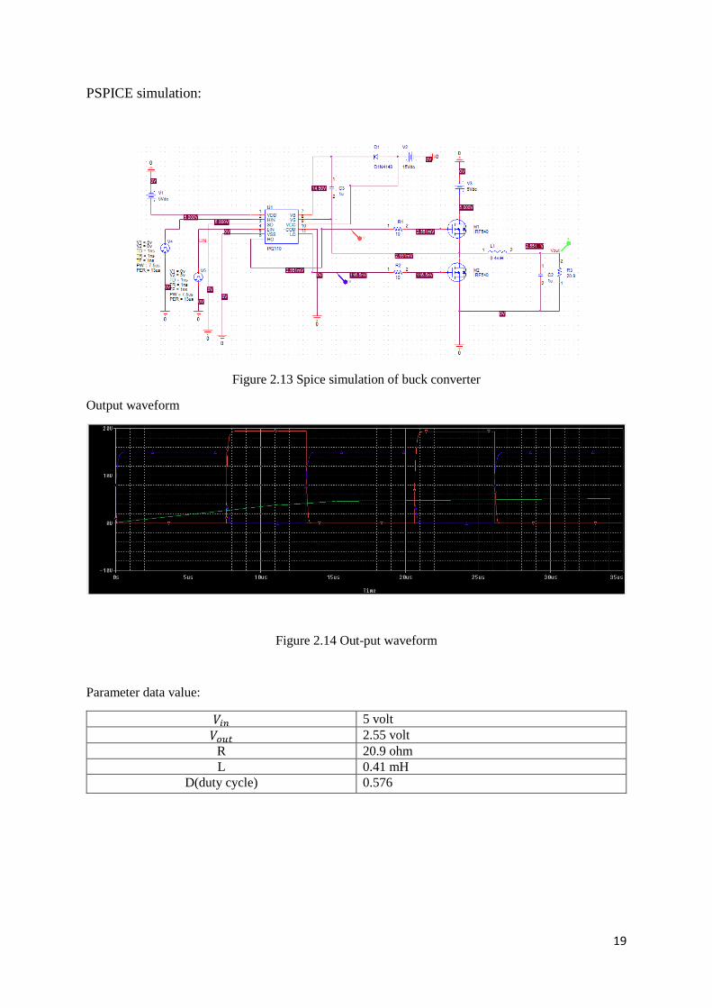
PSPICE simulation:
Figure 2.13 Spice simulation of buck converter
Output waveform
Figure 2.14 Out-put waveform
Parameter data value:
𝑉𝑖𝑛 5 volt
𝑉𝑜𝑢𝑡 2.55 volt
R 20.9 ohm
L 0.41 mH
D(duty cycle) 0.576

20
2.5 SPEED CONTROL OF PMDC MOTOR USING HALF BRIDGE CONVERTER
Figure 2.15 Half Bridge Non-Isolated Bidirectional DC-DC Converter fed PMDC Motor.
The Fig 2.15 depicts us a view of Half Bridge NBDC fed PMDC motor which can be put to
operation in two different modes in which one is boost mode which is for forward motoring
mode of operation and during buck mode we have electrical regeneration. The battery pack can
be placed where we have a low voltage whereas a PMDC motor whose speed has to be
controlled is introduced in the high voltage side. The circuit also consists of a high-frequency
capacitor to guarantee the operation of a smoothening capacitor along the battery side. If the
BDC is working in continuous conduction mode (CCM) then we may be in needing of a larger
valued inductor. Consequently the size of the inductor increments and likewise eases off the
transient response. If the circuit is working in the discontinuous conduction mode (DCM), the
value of the inductor can be extremely lessened and the response gets to be quicker,
subsequently there will be a considerable increase in power density. Zero-turn on loss will be
encouraged by this mode of operation and in this manner less reverse recovery loss in diode.
Anyhow, in the meantime the main switch will be turned off at twofold of estimated average
load current which may in turn increases the losses during this state. By utilizing a snubber
capacitor over the switches this can be diminished. Alongside this, the value of current flowing
through inductor likewise displays parasitic ringing during turning OFF of the switch. This is
on the grounds that the switch's output capacitance in connection with the inductor has a
tendency to oscillate and subsequently causes power dissipation and electrical strain on the
devices.
21
CHAPTER 3
CONCLUSION
Different types of NBDCs topologies are analysed and compared. Among all of them half
bridge BDC is the most suitable for light converter design with higher efficiency and low cost
in HEV.
Based on topology analysis, parameter design is carried out to get appropriate values of
parameter for desired output voltage. Using MATLAB and PSpice simulation output is
obtained and thus verified with output waveforms and thus achieving desired targets.
Schematic diagram of bidirectional DC-DC converter fed PMDC motor is explained.
22
REFERENCES
[1] Mahendra Chandra Joshi and Susovon Samanta, Electrical Engineering Department,
National Institute of Technology, Rourkela, India, “Modelling and Control of Bidirectional
DC-DC Converter Fed PMDC Motor for Electric Vehicles”, 2013 Annual IEEE India
Conference (INDICON)
[2] F.Caricchi, F. Crescimbini, F. Giulii Capponi and L. Solero, University of Rome "La
Sapienza", “Study of Bi-Directional Buck-Boost Converter Topologies for Application in
Electrical Vehicle Motor Drives”, 1998 IEEE.
[3] Jan Leuchter, Pavol Bauer, Petr Bojda and Vladimir Rerucha, University of Defence,
DELFT university of technology “Bi-directional DC-DC converter for super capacitor based
energy buffer for electrical GEN-Sets” EPE 2007 – Aalborg.
[4] Hamid R. Karshenas, Hamid Daneshpajooh, Alireza Safaee, Praveen Jain Praveen Jain and
Alireza Bakhshai, Department of Elec. & Computer Eng., Queen’s University, Kingston,
Isfahan University of Tech., Isfahan, Canada Iran, “Bidirectional DC-DC Converters for
Energy Storage Systems”.
[5] H. Matsuo, K. Iida, F. Kurokawa, H. Kimura, T. Koga and M. Asano “High power buck-
boost type DC-DC converter applied to the auxiliary power source of the electric railway
rolling stock”, Power Electronics Specialists Conference, 1993, 24th Annual IEEE 20-24 Jun
1993.
[6] Nandankar, P. ; Elect. Eng. Dept., Visvesvaraya Nat. Inst. of Technol., Nagpur, India ;
Aware, M.V., “High efficiency discontinuous mode interleaved multiphase bidirectional dc-dc
converter”, Power Electronics, Drives and Energy Systems (PEDES), 2012 IEEE International
Conference , 16-19 Dec. 2012.
[7] Korkmaz, M. ; Dept. of Electr. & Electron. Eng., Selcuk Univ., Konya, Turkey ; Aydogdu,
O. ; Dogan, H., “Design and performance comparison of variable parameter nonlinear PID
controller and genetic algorithm based PID controller”, Innovations in Intelligent Systems and
Applications (INISTA), 2012 International Symposium on , 2-4 July 2012.