DC Isolators: What are the Manufacturer’s Specification Sheets … · 2016-03-24 · Page | 1...
5
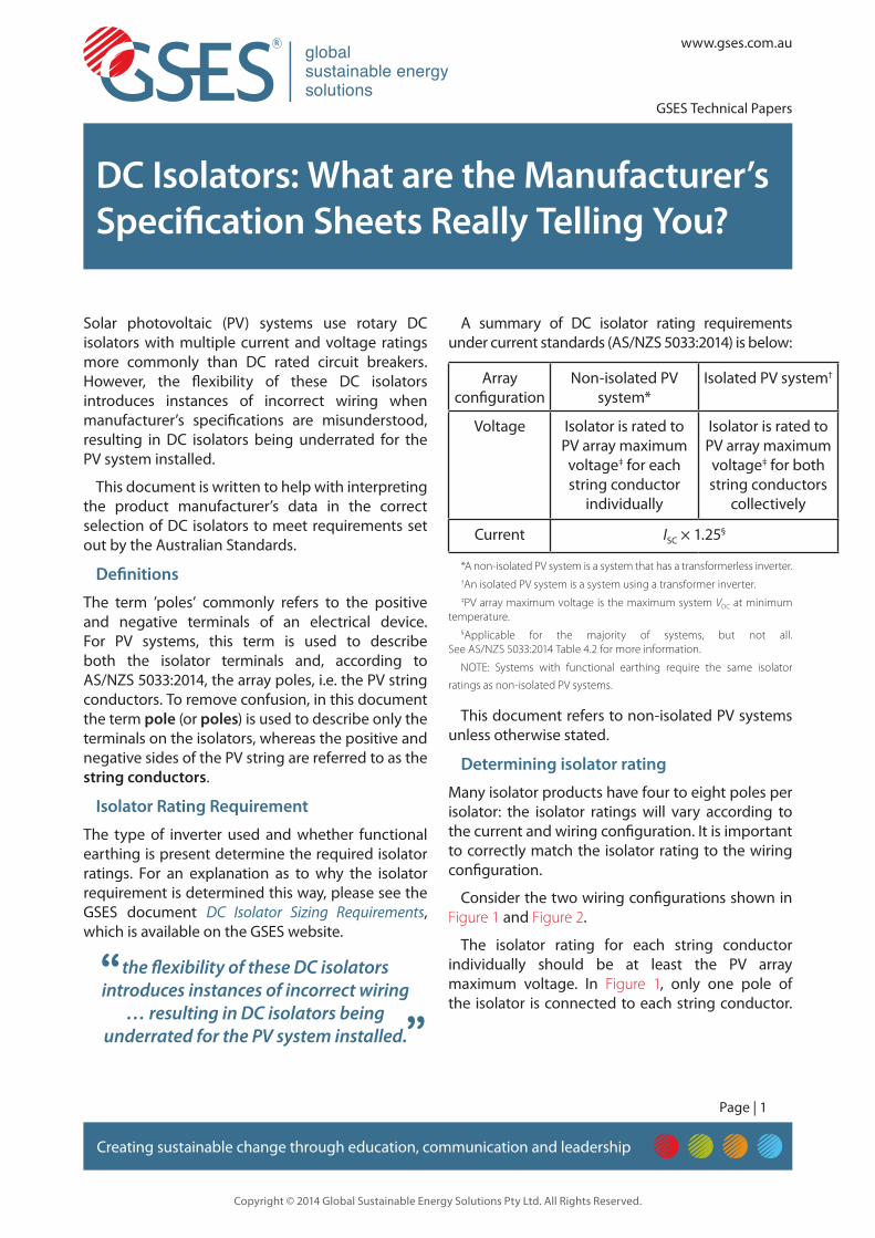
Page | 1 www.gses.com.au GSES Technical Papers Copyright © 2014 Global Sustainable Energy Solutions Pty Ltd. All Rights Reserved. Creating sustainable change through education, communication and leadership DC Isolators: What are the Manufacturer’s Specification Sheets Really Telling You? Solar photovoltaic (PV) systems use rotary DC isolators with multiple current and voltage ratings more commonly than DC rated circuit breakers. However, the flexibility of these DC isolators introduces instances of incorrect wiring when manufacturer’s specifications are misunderstood, resulting in DC isolators being underrated for the PV system installed. This document is written to help with interpreting the product manufacturer’s data in the correct selection of DC isolators to meet requirements set out by the Australian Standards. Definitions The term ’poles’ commonly refers to the positive and negative terminals of an electrical device. For PV systems, this term is used to describe both the isolator terminals and, according to AS/NZS 5033:2014, the array poles, i.e. the PV string conductors. To remove confusion, in this document the term pole (or poles) is used to describe only the terminals on the isolators, whereas the positive and negative sides of the PV string are referred to as the string conductors. Isolator Rating Requirement The type of inverter used and whether functional earthing is present determine the required isolator ratings. For an explanation as to why the isolator requirement is determined this way, please see the GSES document DC Isolator Sizing Requirements, which is available on the GSES website. A summary of DC isolator rating requirements under current standards (AS/NZS 5033:2014) is below: Array configuration Non-isolated PV system* Isolated PV system † Voltage Isolator is rated to PV array maximum voltage ‡ for each string conductor individually Isolator is rated to PV array maximum voltage ‡ for both string conductors collectively Current I SC × 1.25 § *A non-isolated PV system is a system that has a transformerless inverter. † An isolated PV system is a system using a transformer inverter. ‡ PV array maximum voltage is the maximum system V OC at minimum temperature. § Applicable for the majority of systems, but not all. See AS/NZS 5033:2014 Table 4.2 for more information. NOTE: Systems with functional earthing require the same isolator ratings as non-isolated PV systems. This document refers to non-isolated PV systems unless otherwise stated. Determining isolator rating Many isolator products have four to eight poles per isolator: the isolator ratings will vary according to the current and wiring configuration. It is important to correctly match the isolator rating to the wiring configuration. Consider the two wiring configurations shown in Figure 1 and Figure 2. The isolator rating for each string conductor individually should be at least the PV array maximum voltage. In Figure 1 , only one pole of the isolator is connected to each string conductor. the flexibility of these DC isolators introduces instances of incorrect wiring … resulting in DC isolators being underrated for the PV system installed. ” “
Transcript of DC Isolators: What are the Manufacturer’s Specification Sheets … · 2016-03-24 · Page | 1...
Page | 1
www.gses.com.au
GSES Technical Papers
Copyright © 2014 Global Sustainable Energy Solutions Pty Ltd. All Rights Reserved.
Creating sustainable change through education, communication and leadership
DC Isolators: What are the Manufacturer’s Specification Sheets Really Telling You?
Solar photovoltaic (PV) systems use rotary DC isolators with multiple current and voltage ratings more commonly than DC rated circuit breakers. However, the flexibility of these DC isolators introduces instances of incorrect wiring when manufacturer’s specifications are misunderstood, resulting in DC isolators being underrated for the PV system installed.
This document is written to help with interpreting the product manufacturer’s data in the correct selection of DC isolators to meet requirements set out by the Australian Standards.
Definitions
The term ’poles’ commonly refers to the positive and negative terminals of an electrical device. For PV systems, this term is used to describe both the isolator terminals and, according to AS/NZS 5033:2014, the array poles, i.e. the PV string conductors. To remove confusion, in this document the term pole (or poles) is used to describe only the terminals on the isolators, whereas the positive and negative sides of the PV string are referred to as the string conductors.
Isolator Rating Requirement
The type of inverter used and whether functional earthing is present determine the required isolator ratings. For an explanation as to why the isolator requirement is determined this way, please see the GSES document DC Isolator Sizing Requirements, which is available on the GSES website.
A summary of DC isolator rating requirements under current standards (AS/NZS 5033:2014) is below:
Array configuration
Non-isolated PV system*
Isolated PV system†
Voltage Isolator is rated to PV array maximum voltage‡ for each string conductor
individually
Isolator is rated to PV array maximum voltage‡ for both string conductors
collectively
Current ISC × 1.25§
*A non-isolated PV system is a system that has a transformerless inverter.†An isolated PV system is a system using a transformer inverter.‡PV array maximum voltage is the maximum system VOC at minimum
temperature.§Applicable for the majority of systems, but not all.
See AS/NZS 5033:2014 Table 4.2 for more information.
NOTE: Systems with functional earthing require the same isolator
ratings as non-isolated PV systems.
This document refers to non-isolated PV systems unless otherwise stated.
Determining isolator rating
Many isolator products have four to eight poles per isolator: the isolator ratings will vary according to the current and wiring configuration. It is important to correctly match the isolator rating to the wiring configuration.
Consider the two wiring configurations shown in Figure 1 and Figure 2.
The isolator rating for each string conductor individually should be at least the PV array maximum voltage. In Figure 1, only one pole of the isolator is connected to each string conductor.
the flexibility of these DC isolators introduces instances of incorrect wiring
… resulting in DC isolators being underrated for the PV system installed.”“

Page | 2
www.gses.com.au
GSES Technical Papers
Copyright © 2014 Global Sustainable Energy Solutions Pty Ltd. All Rights Reserved.
Creating sustainable change through education, communication and leadership
DC Isolators: What are the Manufacturer’s Specification Sheets Really Telling You?
Therefore, the isolator’s single pole voltage rating at the current requirement must be greater than the array’s maximum voltage as calculated. In Figure 2, two poles are connected in series to each string conductor. In this example, the voltage rating of the isolator having two poles in series must be greater than the array’s maximum voltage.
By identifying the number of isolator poles used by each string conductor, designers can ensure that they are referring to the correct isolator rating in the manufacturer’s specifications.
Manufacturer’s Specifications
Rotary DC isolators generally have varying voltage ratings depending on the system’s current. This information is typically presented in the following format:
Array configuration Voltage rating (V)
Current rating (A)
One pole 300 23
500 11
800 4
Two poles in series 500 25
800 20
1000 11
1500 4
Four poles in series 500 25
800 25
1000 25
1500 20
A simplified table is often included on the isolator or isolator enclosure; for example:
500 V 800 V 1000 V 1500 V
2 P 25 A 20 A 11 A 4A
4 P 25 A 25 A 25 A 20 A
Manufacturer’s Connection Diagrams
Connection diagrams are provided by manufacturers to illustrate the isolator’s internal connections and isolator ratings at different configurations. However, these diagrams should not be used to determine the isolator rating, as the connection diagrams generally do not match the ratings needed for non-isolated PV systems.
For example, a manufacturer can provide the connection diagram shown in Figure 3 for two poles in series.
When the isolator is connected to a non-isolated system as shown in Figure 3, the single pole rating, instead of the two poles in series rating, must be used to meet the isolator rating requirements. This is because only one pole is being used per string
Figure 2: Schematic and photo showing two poles in series used per string conductor.
PV module
DC isolator
Inverter
PV module
DC isolator
Inverter
Figure 1: Schematic and photo showing a single pole of the isolator used per string conductor.
Page | 3
www.gses.com.au
GSES Technical Papers
Copyright © 2014 Global Sustainable Energy Solutions Pty Ltd. All Rights Reserved.
Creating sustainable change through education, communication and leadership
DC Isolators: What are the Manufacturer’s Specification Sheets Really Telling You?
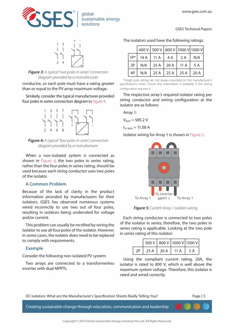
conductor, so each pole must have a rating greater than or equal to the PV array maximum voltage.
Similarly, consider the typical manufacturer-provided four poles in series connection diagram in Figure 4.
When a non-isolated system is connected as shown in Figure 4, the two poles in series rating, rather than the four poles in series rating, should be used because each string conductor uses two poles of the isolator.
A Common Problem
Because of the lack of clarity in the product information provided by manufacturers for their isolators, GSES has observed numerous systems wired incorrectly to use two out of four poles, resulting in isolators being underrated for voltage and/or current.
This problem can usually be rectified by wiring the isolator to use all four poles of the isolator. However, in some cases, the isolator does need to be replaced to comply with requirements.
Example
Consider the following non-isolated PV system:
Two arrays are connected to a transformerless inverter with dual MPPTs.
The isolators used have the following ratings:
400 V 500 V 800 V 1000 V 1500 V
1P* 14 A 11 A 4 A 2 A N/A
2P N/A 25 A 20 A 11 A 5 A
4P N/A 25 A 25 A 25 A 20 A
*Single pole ratings are not always provided on the manufacturer’s specifications sheet. Ensure this information is available if the wiring
configuration requires it.
The respective array’s required isolator rating per string conductor and wiring configuration at the isolator are as follows:
Array 1:
VMAX = 585.2 V
ISC MAX = 11.58 A
Isolator wiring for Array 1 is shown in Figure 5.
Each string conductor is connected to two poles of the isolator in series; therefore, the two poles in series rating is applicable. Looking at the two pole in series rating of this isolator:
500 V 800 V 1000 V 1500 V
2P 25 A 20 A 11 A 5 A
Using the compliant current rating, 20A, the isolator is rated to 800 V, which is well above the maximum system voltage. Therefore, this isolator is rated and wired correctly.
Figure 3: A typical ‘two poles in series’ connection diagram provided by a manufacturer.
2 4
1 3+ –
Figure 4: A typical ‘four poles in series’ connection diagram provided by a manufacturer.
6 8
5 7
2 4
1 3
+ –
To Array 1 To Array 1To inverter
MPPT 1
Figure 5: Current Array 1 isolator wiring.
Page | 4
www.gses.com.au
GSES Technical Papers
Copyright © 2014 Global Sustainable Energy Solutions Pty Ltd. All Rights Reserved.
Creating sustainable change through education, communication and leadership
DC Isolators: What are the Manufacturer’s Specification Sheets Really Telling You?
Array 2:
VMAX = 498.4 V
ISC MAX = 11.58 A
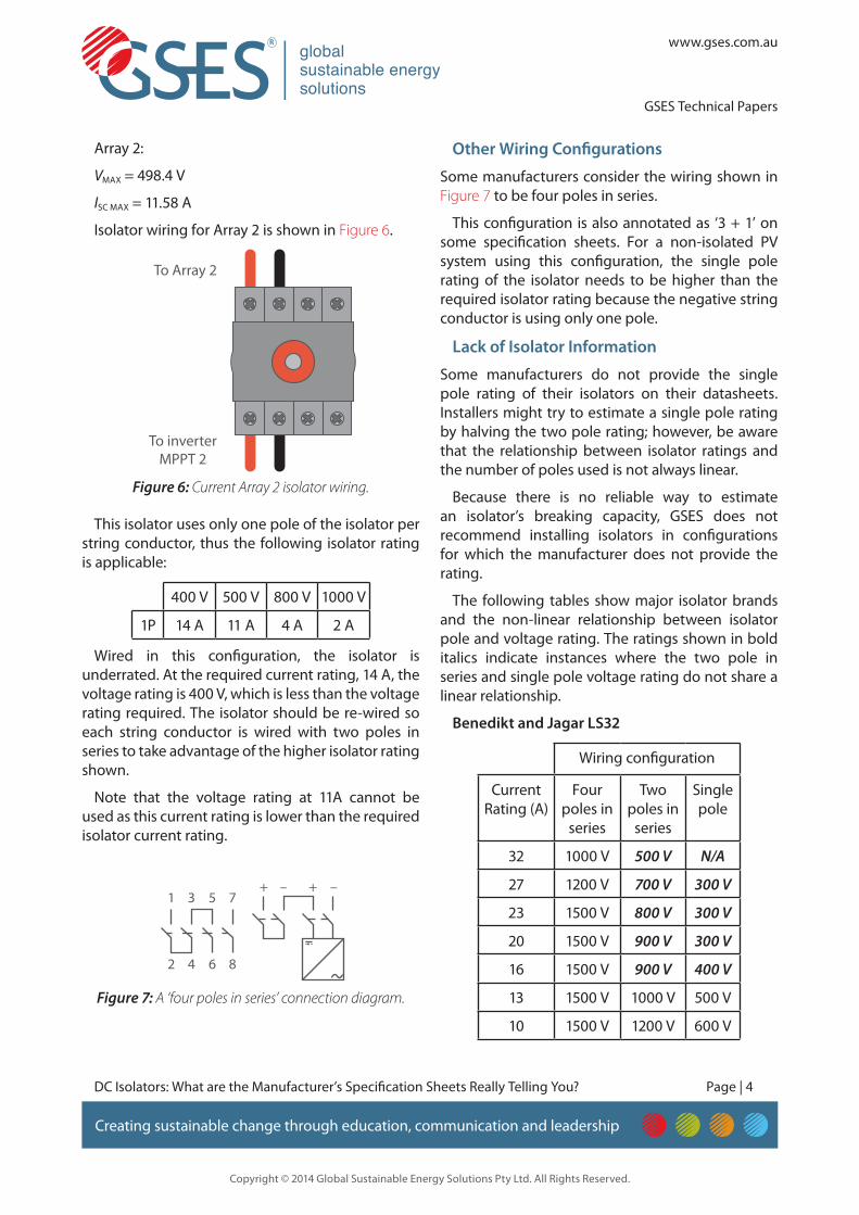
Isolator wiring for Array 2 is shown in Figure 6.
This isolator uses only one pole of the isolator per string conductor, thus the following isolator rating is applicable:
400 V 500 V 800 V 1000 V
1P 14 A 11 A 4 A 2 A
Wired in this configuration, the isolator is underrated. At the required current rating, 14 A, the voltage rating is 400 V, which is less than the voltage rating required. The isolator should be re-wired so each string conductor is wired with two poles in series to take advantage of the higher isolator rating shown.
Note that the voltage rating at 11A cannot be used as this current rating is lower than the required isolator current rating.
Other Wiring Configurations
Some manufacturers consider the wiring shown in Figure 7 to be four poles in series.
This configuration is also annotated as ‘3 + 1’ on some specification sheets. For a non-isolated PV system using this configuration, the single pole rating of the isolator needs to be higher than the required isolator rating because the negative string conductor is using only one pole.
Lack of Isolator Information
Some manufacturers do not provide the single pole rating of their isolators on their datasheets. Installers might try to estimate a single pole rating by halving the two pole rating; however, be aware that the relationship between isolator ratings and the number of poles used is not always linear.
Because there is no reliable way to estimate an isolator’s breaking capacity, GSES does not recommend installing isolators in configurations for which the manufacturer does not provide the rating.
The following tables show major isolator brands and the non-linear relationship between isolator pole and voltage rating. The ratings shown in bold italics indicate instances where the two pole in series and single pole voltage rating do not share a linear relationship.
Benedikt and Jagar LS32
Wiring configuration
Current Rating (A)
Four poles in
series
Two poles in
series
Single pole
32 1000 V 500 V N/A
27 1200 V 700 V 300 V
23 1500 V 800 V 300 V
20 1500 V 900 V 300 V
16 1500 V 900 V 400 V
13 1500 V 1000 V 500 V
10 1500 V 1200 V 600 V
To Array 2
To inverterMPPT 2
Figure 6: Current Array 2 isolator wiring.
Figure 7: A ‘four poles in series’ connection diagram.
6 8
5 7
2 4
1 3+ + ––

Page | 5
www.gses.com.au
GSES Technical Papers
Copyright © 2014 Global Sustainable Energy Solutions Pty Ltd. All Rights Reserved.
Creating sustainable change through education, communication and leadership
DC Isolators: What are the Manufacturer’s Specification Sheets Really Telling You?
Telegron TFV50 series
Wiring configuration
Current rating (A)
Four poles in
series
Two poles in
series
Single pole
50 1000 V 400 V 200 V
40 1000 V 500 V 250 V
25 1000 V 600 V 300 V
10 1000 V 850 V 450 V
8 1000 V 1000 V 500 V
Zj-BENY BYH-32
Wiring configuration
Current rating (A)
Four poles in
series
Two poles in
series
Single pole
32 1000 V 500 V N/A
32 1000 V 600 V N/A
23 1000 V 800 V N/A
13 1000 V 1000 V N/A
Conclusion
GSES recommends that installers and designers consult the manufacturer’s isolator rating with the system’s wiring configuration and the rating requirement in mind and only use configurations that are provided with manufacturer’s rating. This will ensure that the PV system can be isolated safely even in fault conditions.
GSES welcomes feedback on technical papers and other resources available on www.gses.com.au, please contact GSES by email at [email protected] or by telephone on 1300 265 525.