Ferrite Domen - Waveguide Circulators, Isolators …Waveguide Circulators, Isolators Part 2...
18
Waveguide Circulators, Isolators Part 2 Waveguide Circulators, Isolators FERRITE DOMEN Co. Since 1959 Ferrite Domen Co. presents a broad range of waveguide ferrite circulators and isolators for use in military, commercial and scientific applications here. We design and manufacture devices from 1.7 to 170 GHz. These ones feature low insertion loss, high isolation, wide spectrum operating power and temperature range. CONTENTS Low Power Waveguide Circulators and Isolators Frequency range Page 1. Broad Bandwidth Circulators and Isolators (Y & T - junction) 3.95 to 26.5 GHz 2-2 2. Low Loss Circulators and Isolators (T - junction) 3.7 to 26.5 GHz 2-2 3. Low Loss Circulators and Isolators for Communication Equipment (cm-wave) 8.7 to 24.5 GHz 2-4 4. Low Loss Circulators and Isolators for Communication Equipment (mm-wave) 26.5 to 170 GHz 2-5 5. Low Loss Circulators and Isolators for General Use (mm-wave) 26.5 to 40 GHz 2-5 6. 1/4" Slim Line Isolators 6.1. Broadband Isolator with Receive Channel 20.5 to 26.5 GHz 2-7 6.2. Double Isolators 21.2 to 26.55 GHz 2-7 7. Cryogenic (4 to 77 K) T - junction Circulators and Isolators (cm-wave) 8.2 to 26.5 GHz 2-8 8. Cryogenic (4 to 77 K) Waveguide Circulators and Isolators (mm-wave) 26.5 to 150 GHz 2-9 9. Broad Bandwidth (Faraday Rotational) Isolators (mm-wave) 26.5 to 170 GHz 2-10 High Power Waveguide Circulators and Isolators Frequency range 10. High Power Y-junction Circulators and Isolators (cm-wave) 2.2 to 12.4 GHz 2-11 11. High Power Y-junction Circulators and Isolators (mm-wave) 26.5 to 60 GHz 2-12 12. 4-port Phase Shift Waveguide Circulators and Isolators (cm-wave) 1.7 to 2.6 GHz 2-13 13. 4-port Phase Shift Waveguide Circulators and Isolators (mm- wave) 26.5 to 60 GHz 2-15 14. Ultra High Power Isolators (mm-wave) 33 to 37 GHz 2-16 15. Circulators and Isolators for Space Application 3.4 to 9 GHz 2-17 Device Applications. How to Order. 2-18 FERRITE DOMEN Co. 25, Tsvetochnaya st., Bld. 3 196084 St. Petersburg, Russia Fax +7 (812) 676 2929 E-mail: [email protected] www.ferrite-domen.com
Transcript of Ferrite Domen - Waveguide Circulators, Isolators …Waveguide Circulators, Isolators Part 2...

Waveguide Circulators, Isolators Part 2
Waveguide Circulators, Isolators
FERRITE DOMEN Co. Since 1959
Ferrite Domen Co. presents a broad range of waveguide ferrite circulators and isolators for use in military, commercial and scientific applications here. We design and manufacture devices from 1.7 to 170 GHz. These ones feature low insertion loss, high isolation, wide spectrum operating power and temperature range.
CONTENTS
Low Power Waveguide Circulators and Isolators Frequency range Page 1. Broad Bandwidth Circulators and Isolators (Y & T - junction) 3.95 to 26.5 GHz 2-2 2. Low Loss Circulators and Isolators (T - junction) 3.7 to 26.5 GHz 2-2 3. Low Loss Circulators and Isolators for Communication Equipment (cm-wave) 8.7 to 24.5 GHz 2-4 4. Low Loss Circulators and Isolators for Communication Equipment (mm-wave) 26.5 to 170 GHz 2-5 5. Low Loss Circulators and Isolators for General Use (mm-wave) 26.5 to 40 GHz 2-5 6. 1/4" Slim Line Isolators
6.1. Broadband Isolator with Receive Channel 20.5 to 26.5 GHz 2-7 6.2. Double Isolators 21.2 to 26.55 GHz 2-7
7. Cryogenic (4 to 77 K) T - junction Circulators and Isolators (cm-wave) 8.2 to 26.5 GHz 2-8 8. Cryogenic (4 to 77 K) Waveguide Circulators and Isolators (mm-wave) 26.5 to 150 GHz 2-9 9. Broad Bandwidth (Faraday Rotational) Isolators (mm-wave) 26.5 to 170 GHz 2-10
High Power Waveguide Circulators and Isolators Frequency range 10. High Power Y-junction Circulators and Isolators (cm-wave) 2.2 to 12.4 GHz 2-11 11. High Power Y-junction Circulators and Isolators (mm-wave) 26.5 to 60 GHz 2-12 12. 4-port Phase Shift Waveguide Circulators and Isolators (cm-wave) 1.7 to 2.6 GHz 2-13 13. 4-port Phase Shift Waveguide Circulators and Isolators (mm- wave) 26.5 to 60 GHz 2-15 14. Ultra High Power Isolators (mm-wave) 33 to 37 GHz 2-16 15. Circulators and Isolators for Space Application 3.4 to 9 GHz 2-17
Device Applications. How to Order. 2-18
FERRITE DOMEN Co. 25, Tsvetochnaya st., Bld. 3
196084 St. Petersburg, RussiaFax +7 (812) 676 2929 E-mail: [email protected]
www.ferrite-domen.com

2-2 Low Power Waveguide Circulators and Isolators
1. Broad Bandwidth Circulators and Isolators (Y & T - junction)
3.95 to 26.5 GHz
Frequency range GHz Model Bandwidth Insertion loss
dB, max IsolationdB, min
VSWR max
Operating temperature°C
3.95 - 5.85 3 WY49-1 Full 0.3 20 1.22 + 250.5 18 1.3 -30 to +70
5.85 - 8.2 3 WY70-1 Full 0.3 20 1.22 + 250.5 18 1.3 -30 to +70
7.05 - 10.0 3 WY85-1 Full 0.3 20 1.22 + 250.5 18 1.3 -30 to +70
8.2 - 12.4 4 WY10-1 Full 0.3 20 1.22 + 250.5 18 1.3 -30 to +70
8.0 - 18 4CWY13-1 Full 0.7 13 1.6 -30 to +70
12.4 - 18.0 4 WY15-1 Full 0.3 20 1.22 + 250.5 18 1.3 -30 to +70
18.0 - 26.5 4 WY22-1 Full 0.35 20 1.22 + 250.5 18 1.3 -30 to +70
2. Low Loss Circulators and Isolators (T - junction) 3.7 to 26.5 GHz
Frequency range
GHz Model Bandwidth Insertion lossdB, max
Isolation dB, min
VSWRmax
3.7 - 4.2 3 WN40-2 Full 0.15 25 1.13 5.92 - 6.43 3 WN62-2 Full 0.15 25 1.13 6.42 - 7.13 3 WN68-2 Full 0.15 25 1.13 7.12 - 7.73 3 WN70-2 Full 0.15 25 1.13 7.72 - 8.4 3 WN80-2 Full 0.15 25 1.13 10.7 - 11.7 4 WN11-2 Full 0.15 25 1.13 10.7 - 12.5 4 WN12-2 Full 0.2 25 1.13 14.0 - 14.5 4 WN14-2 Full 0.2 25 1.13 17.7 - 19.7 4 WN18-2 Full 0.2 25 1.13 21,2 - 24.5 4 WN23-2 Full 0.2 23 1.16 24.5 - 26.5 4 WN25-2 Full 0.2 23 1.16 Note. Operating temperature range (0 to +50)°C
In blank : I - Isolator, C- Circulator. At ordering please specify type of device in the model number (see page 2-18).

Low Power Waveguide Circulators and Isolators 2-3
Package Size (mm)
1. Broad Bandwidth Circulators and Isolators (Y & T - junction)
Model L W H Waveguide 3 WY49-1 100 110 60 WR-187 3 WY70-1 70 79 54 WR-137 3 WY85-1 68 65 47 WR-112 4 WY10-1 50 55 42 WR-90 4CWY13-1 78 67.7 35 Single-ridge 4 WY15-1 40 48 35 WR-62 4 WY22-1 32 39 29 WR-42
2. Low Loss Circulators and Isolators (T - junction)
Model L W H Waveguide 3 WN40-2 120 128 63 WR-229 3 WN62-2 90 85 53 WR-137 3 WN68-2 90 85 53 WR-137 3 WN70-2 68 65 47 WR-112 3 WN80-2 68 65 47 WR-112 4 WN11-2 50 55 42 WR-90 4 WN12-2 45 45 38.5 WR-75 4 WN14-2 40 48 35 WR-62 4 WN18-2 32 39 22.5 WR-42 4 WN23-2 32 39 22.5 WR-42 4 WN25-2 32 39 22.5 WR-42
Note! Dimensions are given for circulators. Isolator dimensions are defined by connected load, which depends on absorbed power.
Dimensions and flange types are specified by agreement with customer.
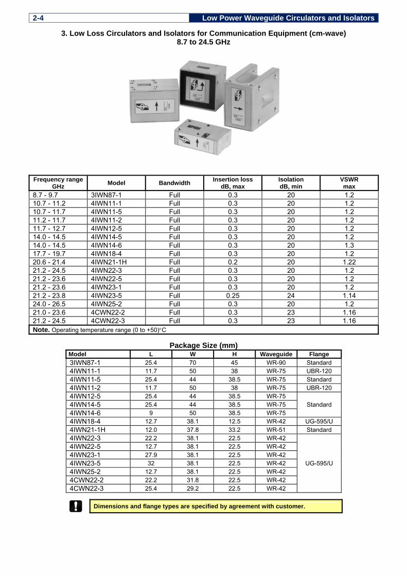
2-4 Low Power Waveguide Circulators and Isolators
3. Low Loss Circulators and Isolators for Communication Equipment (cm-wave) 8.7 to 24.5 GHz
Frequency range
GHz Model Bandwidth Insertion lossdB, max
Isolation dB, min
VSWRmax
8.7 - 9.7 3IWN87-1 Full 0.3 20 1.2 10.7 - 11.2 4IWN11-1 Full 0.3 20 1.2 10.7 - 11.7 4IWN11-5 Full 0.3 20 1.2 11.2 - 11.7 4IWN11-2 Full 0.3 20 1.2 11.7 - 12.7 4IWN12-5 Full 0.3 20 1.2 14.0 - 14.5 4IWN14-5 Full 0.3 20 1.2 14.0 - 14.5 4IWN14-6 Full 0.3 20 1.3 17.7 - 19.7 4IWN18-4 Full 0.3 20 1.2 20.6 - 21.4 4IWN21-1H Full 0.2 20 1.22 21.2 - 24.5 4IWN22-3 Full 0.3 20 1.2 21.2 - 23.6 4IWN22-5 Full 0.3 20 1.2 21.2 - 23.6 4IWN23-1 Full 0.3 20 1.2 21.2 - 23.8 4IWN23-5 Full 0.25 24 1.14 24.0 - 26.5 4IWN25-2 Full 0.3 20 1.2 21.0 - 23.6 4CWN22-2 Full 0.3 23 1.16 21.2 - 24.5 4CWN22-3 Full 0.3 23 1.16 Note. Operating temperature range (0 to +50)°C
Package Size (mm)
Model L W H Waveguide Flange 3IWN87-1 25.4 70 45 WR-90 Standard 4IWN11-1 11.7 50 38 WR-75 UBR-120 4IWN11-5 25.4 44 38.5 WR-75 Standard 4IWN11-2 11.7 50 38 WR-75 UBR-120 4IWN12-5 25.4 44 38.5 WR-75
Standard 4IWN14-5 25.4 44 38.5 WR-75 4IWN14-6 9 50 38.5 WR-75 4IWN18-4 12.7 38.1 12.5 WR-42 UG-595/U 4IWN21-1H 12.0 37.8 33.2 WR-51 Standard 4IWN22-3 22.2 38.1 22.5 WR-42
UG-595/U
4IWN22-5 12.7 38.1 22.5 WR-42 4IWN23-1 27.9 38.1 22.5 WR-42 4IWN23-5 32 38.1 22.5 WR-42 4IWN25-2 12.7 38.1 22.5 WR-42 4CWN22-2 22.2 31.8 22.5 WR-42 4CWN22-3 25.4 29.2 22.5 WR-42
Dimensions and flange types are specified by agreement with customer.

Low Power Waveguide Circulators and Isolators 2-5
4. Low Loss Circulators and Isolators for Communication Equipment (mm-wave)
26.5 to 170 GHz
Frequency range GHz Model Bandwidth
%Insertion loss
dB, max IsolationdB, min
VSWR max
Operating temperature°C
26.5 - 40 4 WN[26-40]-1 20 0.3 20 1.25 +25 0.4 18 1.3 -30 to +85
26.5 - 40 4 WN[26-40]-2 15 0.2 20 1.2 +25 0.25 18 1.25 -30 to +85
33 - 50 4 WN[33-50]-1 15 0.3 20 1.25 +25 0.4 18 1.3 -30 to +85
40 - 60 4 WN[40-50]-1 10 0.3 20 1.25 +25 0.3 18 1.3 -30 to +85
50 - 75 4 WN[50-75]-1 5 0.4 20 1.25 +25 0.4 18 1.3 -30 to +85
60 - 90 4 WN[60-90]-1 5 0.4 20 1.25 +25 0.4 18 1.3 -30 to +85
75 - 99 4 WN[75-99]-1 3.5 0.4 20 1.25 +25 0.4 18 1.3 -30 to +85
90 - 99 4 WN[90-99]-1 3 0.7 20 1.25 +25 0.7 18 1.3 (-10 to +70
100 - 110 5 WN[10-11]-1 3.5 0.4 20 1.25 +25 0.4 18 1.3 (-10 to +70
100 - 140 5 WN[10-14]-1 3 0.7 20 1.25 +25 0.7 18 1.3 (-10 to +70
110 - 170 5 WN[11-17]-1 2 0.8 18 1.3 +25 0.8 18 1.3 (-10 to +70
Notes. Average power: for isolators - 1 W, for circulator - 2 W.
In blank : I - Isolator, C- Circulator. At ordering please specify type of device in the model number (see page 2-18).
[X-X] - Group of Models, each for a definite central frequency of the range. While ordering a particular Model, central frequency of the range should be stated (see "Device Application. How to Order", page 2-18).
5. Low Loss Circulators and Isolators for General Use (mm-wave)
26.5 to 40 GHz
Frequency range GHz Model Bandwidth Insertion loss
dB, max Isolation dB, min
VSWRmax
26.5 to 40 4 WY33-1 Full
0.6 15 1.45 26 to 30 4 WN28-2 0.3 20 1.2 37 to 40 4 WN38-2 0.3 20 1.2 Note. Operating temperature range (0 to +50) °C.

2-6 Low Power Waveguide Circulators and Isolators
Package Size (mm)
4. Low Loss Circulators and Isolators for Communication Equipment (mm-wave)
Isolator Circulator L W H Waveguide Flange4IWN[26-40]-1 15 32 20
WR-28 UG-599/U 4CWN[26-40]-1 19.1 25 20 4IWN[26-40]-2 15 32 20 4CWN[26-40]-2 19.1 25 20 4IWN[33-50]-1 15 32 20 WR-22 UG-599/U 4CWN[33-50]-1 19.1 25 20 4IWN[40-50]-1 15 32 31 WR-19 UG-383/U 4CWN[40-50]-1 34 34 31 4IWN[50-75]-1 19.1 32 21 WR-15 UG-385/U 4CWN[50-75]-1 19.1 25 23 4IWN[60-90]-1 13 25 22 WR-12 UG-387/U 4CWN[60-90]-1 25 25 23 4IWN[75-99]-1 12 25 22
WR-10 UG-387/U 4CWN[75-99]-1 25 25 23 4IWN[90-99]-1 12 25 22 4CWN[90-99]-1 25 25 23 5IWN[10-11]-1 12 25 22 5CWN[10-11]-1 25 25 23
WR-8 UG-387/U 5IWN[10-14]-1 12 25 22 5CWN[10-14]-1 25 25 23 5IWN[11-17]-1 12 25 22 WR-6 UG-387/U 5CWN[11-17]-1 25 25 23
5. Low Loss Circulators and Isolators for General Use (mm-wave)
Isolator Circulator L W H Waveguide Flange4IWY33-1 12.7 32 20
WR-28 UG-599/U
4CWY33-1 19.05 25 20 4IWN28-2 12.7 32 20 4CWN28-2 25.4 25.4 20 4IWN38-2 12.7 32 20 4CWN38-2 25.4 25.4 20
Dimensions and flange types are specified by agreement with customer.

Low Power Waveguide Circulators and Isolators 2-7
6. 1/4" Slim Line Isolators
6.1. Broadband Isolator with Receive Channel
20.5 to 26.5 GHz
Frequency range GHz Model Insertion loss
dB, max Isolation dB, min
VSWR max
Power W
Extended receivingfrequency range
Frequency GHz
IsolationdB min
20.5 - 24.0 4IWL-22X 0.6 15 1.4 2 ― ― 24.0 - 26.5 4IWL-25X 0.6 15 1.4 2 ― ― 22.43 - 23.03 4IWL23-A 0.6 18 1.3 2 23.03 - 26.04 10 23.0 - 23.6 4IWL23-D 0.6 18 1.3 2 23.6 - 26.6 10 21.2 - 21.6 4IWL23-C 0.6 18 1.3 2 18.19 - 21.2 10 21.7 - 22.4 4IWL23-D 0.6 18 1.3 2 18.75 - 21.76 10 23.0 - 23.6 4IWL23-E 0.6 18 1.3 2 23.6 - 26.1 10 22.0 - 22.6 4IWL23-F 0.6 18 1.3 2 19.9 - 22.0 10 25.475 - 26.075 4IWL26-A 0.6 18 1.3 2 26.075 - 28.5 10 25.95 - 26.55 4IWL26-B 0.6 18 1.3 2 26.55 - 28.5 10 24.475 - 25.075 4IWL26-C 0.6 18 1.3 2 21.471 - 24.478 10 25.95 - 26.55 4IWL26-D 0.6 18 1.3 2 21.325 - 24.93 10
6.2. Double Isolators 21.2 to 25.53 GHz
Frequency GHz Model Channel
Insertionloss
dB, max Isolation dB, min
VSWR max
Power W
Extended receiving frequency range
Frequency GHz
IsolationdB min
21.2 - 21.8 4IWD-23A T 0.5 18 1.3 2 23.03 - 26.04 10 22.43 - 23.03 R 0.6 21.76 - 22.36 4IWD-23B T 0.5 18 1.3 2 23.6 - 26.6 10 23.0 - 23.6 R 0.6 22.43 - 23.1 4IWD-23C T 0.5 18 1.3 2 18.19 - 21.2 10 21.2 - 21.8 R 0.6 23.0 - 23.6 4IWD-23D T 0.5 18 1.3 2 18.75 - 21.76 10 21.7 - 22.4 R 0.6 22.0 - 22.6 4IWD-23E T 0.5 18 1.3 2 23.6 - 26.1 10 23.0 - 23.6 R 0.6 23.0 - 23.6 4IWD-23F T 0.5 18 1.3 2 19.9 - 22.0 10 22.0 - 22.6 R 0.6 24.475 - 25.075 4IWD-26A T 0.5 18 1.3 2 26.075 - 28.5 10 25.475 - 26.075 R 0.6 24.91 - 25.53 4IWD-26B T 0.5 18 1.3 2 26.55 - 28.5 10 25.95 - 26.55 R 0.6 25.475 - 26.075 4IWD-26C T 0.5 18 1.3 2 21.471 -
24.475 10 24.475 - 25.075 R 0.6 25.95 - 26.55 4IWD-26D T 0.5 18 1.3 2 21.326 - 24.93 10 24.93 - 25.53 R 0.6 Notes. Temperature range for all slim line isolators: (-30 to +70) oC. Waveguide type - WR-42
23 0.0445
24 0
.04
45
+
+
WR-42
3.15 0.03 dia4 holes+
R
A...F
T
(Recive channel)
(Transmit channel)
6 0.05+0.02 0.02

2-8 Low Power Waveguide Circulators and Isolators
7. Cryogenic (4 to 77 K) T - junction Waveguide Circulators and Isolators (cm-wave) 8.2 to 26.5 GHz
Frequency range GHz Model Bandwidth
%Insertion loss
dB, max Isolation dB, min
VSWRmax
8.2 - 9.9 3 WC[80-90]-1 15 0.2 20 1.22 10 - 12.4 4 WC[10-12]-1 15 0.2 20 1.22 12.4 - 18.0 4 WC[12-18]-1 15 0.2 20 1.22 12.4 - 18.0 4 WC15-2 Full 0.3 20 1.22 18.0 - 26.5 4 WC[18-26]-1 15 0.2 20 1.22
In blank : I - Isolator, C- Circulator. At ordering please specify type of device in the model number (see page 2-18).
[X-X] - Group of Models, each for a definite central frequency of the range. While ordering a particular Model, central frequency of the range should be stated (see "Device Application. How to Order", page 2-18).
Package Size (mm)
Model L W H Waveguide 3 WC[80-90]-1 55 51 43 WR-90 4 WC[10-12]-1 40.5 32 33.5 WR-62 4 WC[12-18]-1 40.5 32 33.5 WR-62 4 WC15-2 40.5 32 33.5 WR-62 4 WC[18-26]-1 32 39 23 WR-42
Note! Dimensions are given for circulators. Isolator dimensions are defined by connected load, which depends on absorbed power.

Low Power Waveguide Circulators and Isolators 2-9
8. Cryogenic (4 to 77 K) Waveguide Circulators and Isolators (mm-wave) 26.5 to 150 GHz
Frequency range GHz Model Bandwidth
%Insertion loss
dB, max Isolation dB, min
VSWRmax
26.5 - 40 4 WC[26-40]-1 12 0.3 20 1.3 33 - 50 4 WC[33-50]-1 8 0.4 20 1.3 40 - 60 4 WC[40-60]-1 5 0.4 20 1.3 50 - 75 4 WC[50-75]-1 5 0.4 20 1.3 60 - 90 4 WC[60-90]-1 4 0.5 20 1.3 75 - 99 4 WC[75-99]-1 3 0.5 20 1.3 90 - 99 4 WC[90-99]-1 2 0.6 20 1.3 100 - 110 5 WC[10-11]-1 3 0.5 20 1.3 100 - 140 5 WC[10-14]-1 2 0.6 20 1.3 110 - 150 5 WC[11-15]-1 2 0.8 20 1.3
In blank : I - Isolator, C- Circulator. At ordering please specify type of device in the model number (see page 2-18).
[X-X] - Group of Models, each for a definite central frequency of the range. While ordering a particular Model, central frequency of the range should be stated (see "Device Application. How to Order", page 2-18).
Package Size (mm)
Isolator Circulator L W H Waveguide Flange
4IWC[26-40]-1 15 32 22 WR-28 UG-599/U 4CWC[26-40]-1 19.1 25 22 4IWC[33-50]-1 15 32 22 WR-22 UG-599/U 4CWC[33-50]-1 19.1 25 22 4IWC[40-60]-1 15 32 31 WR-19 UG-383/U 4CWC[40-60]-1 34 34 31 4IWC[50-75]-1 19.1 32 21 WR-15 UG-385/U 4CWC[50-75]-1 19.1 25 23 4IWC[60-90]-1 13 25 22 WR-12 UG-387/U 4CWC[60-90]-1 25 25 23 4IWC[75-99]-1 12 25 22
WR-10 UG-387/U 4CWC[75-99]-1 25 25 23 4IWC[90-99]-1 12 25 22 4CWC[90-99]-1 25 25 23 5IWC[10-11]-1 12 25 22
WR-8 UG-387/U 5CWC[10-11]-1 25 25 23 5IWC[10-14]-1 12 25 22 5CWC[10-14]-1 25 25 23 5IWC[11-15]-1 12 25 22 WR-6 UG-387/U 5CWC[11-15]-1 25 25 23
Dimensions and flange types are specified by agreement with customer.

2-10 Low Power Waveguide Circulators and Isolators
9. Broad Bandwidth (Faraday Rotational) Isolators (mm-wave) 26.5 to 170 GHz
Frequency range
GHz Model Bandwidth Insertion lossdB, max
Isolation dB, min
VSWRmax
26.5 - 40 4IWF33-1 Full 1.5 25 1.4 33 - 50 4IWF42-1 Full 1.8 25 1.4 40 - 60 4IWF50-1 Full 1.8 25 1.45 50 - 75 4IWF63-1 Full 1.8 25 1.45 60 - 90 4IWF75-1 Full 2.0 25 1.5 75 - 110 4IWF93-1 Full 2.5 25 1.5 90 - 140 5IWF12-1 Full 3.0 25 1.5 110 -170 5IWF14-1 Full 3.5 25 1.5 Notes. Operating power 0.5 W. Operating temperature (0 to + 50) °C.
Package Size (mm)
Model L Diameter Waveguide Flange
4IWF33-1 70 30 WR-28 UG-599/U 4IWF42-1 60 30 WR-22 UG-383/U 4IWF50-1 60 30 WR-19 UG-383/U 4IWF63-1 50 30 WR-15 UG-385/U 4IWF75-1 50 25 WR-12 UG-387/U 4IWF93-1 50 25 WR-10 UG-387/U 5IWF12-1 50 25 WR-8 UG-387/U 5IWF14-1 50 25 WR-6 UG-387/U
Dimensions and flange types are specified by agreement with customer.

High Power Waveguide Circulators and Isolators 2-11
10. High Power Waveguide Y-junction Circulators and Isolators (cm-wave) 2.2 to 12.4 GHz
Frequency range GHz
Model Bandwidth %
Insertion loss(Typ∗/Max)
dB
Isolation(Typ∗/Min)
dB
VSWR (Typ∗/Max)
Power, kW
Average Peak
2.20 - 3.30 3IWH28-1 10 0.25/0.3 23/20 1.17/1.2 0.8 3 2.20 - 3.30 3CWH28-1 10 0.25/0.3 23/20 1.17/1.2 0.8 - 2.20 - 3.30 3IWH28-2 10 0.3/0.45 23/20 1.17/1.2 5 500 2.60 - 3.45 3CWH30-1 10 0.25/0.3 23/20 1.17/1.2 3 170 2.60 - 3.45 3CWH30-2 10 0.35/0.4 23/20 1.17/1.2 5 300 4.40 - 7.05 3CWH57-1 10 0.2/0.3 23/20 1.17/1.2 2 300 5.85 - 8.20 3IWH70-1 10 0.25/0.3 23/20 1.17/1.2 2 300 5.85 - 8.20 3CWH70-1 10 0.25/0.3 23/20 1.17/1.2 2 150 7.05 - 10.0 3CWH90-1 15 0.3/0.35 23/20 1.17/1.2 1.5 30 7.05 - 10.0 3CWH90-2 15 0.2/0.25 23/20 1.17/1.2 2 - 7.05 - 10.0 3CWH90-3 15 0.3/0.35 23/20 1.17/1.2 1.8 30 8.2 - 12.4 4CWH10-5 15 0.2/0.25 23/20 1.17/1.2 0.4 200 8.2 - 12.4 4CWH10-6 15 0.2/0.25 23/20 1.17/1.2 1.0 - 8.2 - 12.4 4CWH10-7 15 0.2/0.25 23/20 1.17/1.2 1.5 4.5 Note. ∗ - Typical performance at (+ 25 ± 10) °C. Max and Min values within temperature ranges (-30 to +70) °C.
Liquid or forced air cooling is optional on customer’s request.
Package Size (mm)
Model L W H Waveguide 3IWH28-1 530 215 100
WR-340 3CWH28-1 210 215 100 3IWH28-2 435 217 142 3CWH30-1 180 182 154 WR-284 3CWH30-2 160 180 100 3CWH57-1 102 90 41 WR-159 3IWH70-1 81 161 45 WR-137 3CWH70-1 81 70 45 3CWH90-1 74 65 55
WR-112 3CWH90-2 70 83 47 3CWH90-3 70 83 47 4CWH10-5 56 73 42
WR-90 4CWH10-6 70 70 44 4CWH10-7 56 66 42
Dimensions and flange types are specified by agreement with customer.

2-12 High Power Waveguide Circulators and Isolators
11. High Power Y-junction Circulators and Isolators (mm-wave) 26.5 to 60 GHz
Frequency range GHz
Model Bandwidth%
Insertion lossdB, max
Isolation dB, min
VSWR max
Power, kW
Average Peak
26.5 - 40 4IWH[26-40]-5 15 0.2 23 1.2 0.2 2 26.5 - 40 4IWH[26-40]-6 15 0.2 23 1.2 0.25 - 26.5 - 40 4CWH[26-40]-5 10 0.25 20 1.2 0.2 2 26.5 - 40 4CWH[26-40]-6 10 0.25 20 1.2 0.25 - 33 - 50 4IWH[33-50]-3 6 o.3 20 1.25 0.1 1 33 - 50 4IWH[33-50]-4 6 0.3 20 1.25 0.15 - 33 - 50 4CWH[33-50]-2 8 0.4 20 1.3 0.05 2 33 - 50 4CWH[33-50]-4 5 0.3 20 1.3 0.15 - 40 - 60 4IWH[40-60]-2 8 0.4 20 1.35 0.05 1.5 40 - 60 4IWH[33-50]-3 5 0.4 20 1.3 0.08 - 40 - 60 4CWH[33-50]-2 5 0.5 18 1.35 0.05 1.5 40 - 60 4CWH[33-50]-3 5 0.5 18 1.35 0.08 - Notes. Reflected power 10%. Devices require a forced air cooling. Operating temperature (+ 5 to + 50) °C.
[X-X] - Group of Models, each for a definite central frequency of the range. While ordering a particular Model, central frequency of the range should be stated (see "Device Application. How to Order", page 2-18).
Package Size (mm)
Model L W H Waveguide 4IWH[26-40]-5 45 150 45
WR-28 4IWH[26-40]-6 45 150 45 4CWH[26-40]-5 30 35 40 4CWH[26-40]-6 30 35 40 4IWH[33-50]-3 50 200 50
WR-22 4IWH[33-50]-4 45 150 45 4CWH[33-50]-2 28 35 40 4CWH[33-50]-4 28 35 40 4IWH[40-60]-2 50 200 50
WR-19 4IWH[33-50]-3 50 200 50 4CWH[33-50]-2 28 32 38 4CWH[33-50]-3 28 32 38
Dimensions and flange types are specified by agreement with customer.

High Power Waveguide Circulators and Isolators 2-13
12. 4-port Phase Shift Waveguide Circulators and Isolators (cm-wave) 1.7 to 22 GHz
Frequency range GHz
Model Bandwidth%
Insertion lossdB, max
Isolation dB, min
VSWR max
Power, kW
Average Peak
1.7 - 2.6 3CWP21-1 10 0.9 24 1.1 22 3600 2.2 - 3.3 3CWP28-1 10 0.4 22 1.15 15 2200 2.6 - 3.95 3CWP33-1 10 0.35 20 1.15 30 1500 3.3 - 4.4 3IWP39-1 10 0.6 20 1.15 30 4000 3.95 - 5.85 3CWP49-1 10 0.4 20 1.15 16 1500 3.95 - 5.85 3IWP49-1 5 0.4 20 1.15 20 - 3.95 - 5.85 3CWP49-2 10 0.4 20 1.1 8 - 4.9 - 7.05 3IWP60-1 10 0.4 23 1.1 10 - 4.9 - 7.05 3CWP60-1 10 0.23 20 1.15 5 - 5.85 - 8.2 3CWP70-1 10 0.3 20 1.15 10 - 5.85 - 8.2 3IWP70-1 10 0.3 20 1.15 10 - 7.05 - 10.0 3CWP90-1 10 0.4 20 1.15 5 50 8.2 - 12.4 4CWP10-1 10 0.3 20 1.15 3 30 8.2 - 12.4 4IWP10-1 10 0.3 20 1.15 3 30 8.2 - 12.4 4CWP10-2 10 0.4 20 1.15 10 200 8.2 - 12.4 4CWP10-3 10 0.4 20 1.15 1 120 10 - 15 4CWP13-1 10 0.4 20 1.12 1 150 12.4 - 18.0 4CWP15-1 10 0.4 20 1.15 1.3 33 12.4 - 18.0 4CWP15-2 10 0.3 22 1.15 2 - 15.0 – 22.0 4CWP19-1 10 0.3 20 1.15 1.3 -
Liquid or forced air cooling is optional on customer’s request.

2-14 High Power Waveguide Circulators and Isolators
12. 4-port Phase Shift Waveguide Circulators and Isolators
Package Size (mm)
Model L W H Waveguide 3CWP21-1 1730 438 630 WR-430 3CWP28-1 444 170 380 WR-340 3CWP33-1 900 278 290 WR-284 3IWP39-1 1028 280 312 WR-229 3CWP49-1 625 109 190 WR-187 3IWP49-1 1470 425 310 WR-187 3CWP49-2 655 166 130 WR-187 3IWP60-1 590 170 105 WR-159 3CWP60-1 440 130 95 WR-159 3CWP70-1 455 112 170 WR-137 3IWP70-1 680 175 160 WR-137 3CWP90-1 372 110 80 WR-112 4CWP10-1 337 72 164 WR-90 4IWP10-1 340 74 80 WR-90 4CWP10-2 425 77.5 126.6 WR-90 4CWP10-3 210 65 57 WR-90 4CWP13-1 238 63 62 WR-75 4CWP15-1 250 74 65 WR-62 4CWP15-2 250 168 119 WR-62 4CWP19-1 338 74.5 53 WR-51
Dimensions and flange types are specified by agreement with customer.

High Power Waveguide Circulators and Isolators 2-15
13. 4-port Phase Shift Waveguide Circulators and Isolators (mm-wave) 26.5 to 60 GHz
Frequency range GHz
Model Bandwidth%
Insertion lossdB, max
Isolation dB, min
VSWR max
Power, kW
Average Peak
26.5 - 40 4IWP[26-40]-3 10 0.4 22 1.25 1 100 26.5 - 40 4IWP[26-40]-5 6 0.3 22 1.2 2 70 26.5 - 40 4IWP[26-40]-6 6 0.3 22 1.2 2.5 - 26.5 - 40 4IWP[26-40]-7∗ 10 0.2 24 1.22 0.3 2.5 26.5 - 40 4CWP[26-40]-3 5 0.4 20 1.2 1 100 26.5 - 40 4CWP[26-40]-4 5 0.4 20 1.2 1.5 70 26.5 - 40 4CWP[26-40]-5 5 0.4 20 1.2 2 70 26.5 - 40 4CWP[26-40]-6 5 0.4 20 1.2 2.5 - 33 - 50 4IWP[33-50]-2 6 0.5 20 1.3 0.5 10 33 - 50 4IWP[33-50]-3 6 0.5 20 1.3 1 - 33 - 50 4CWP[33-50]-2 5 0.6 18 1.3 0.5 10 33 - 50 4CWP[33-50]-3 5 0.6 18 1.3 1 - 40 - 60 4IWP[40-60]-2 6 0.55 20 1.35 0.3 5 40 - 60 4IWP[40-60]-3 6 0.55 20 1.35 0.7 - 40 - 60 4CWP[40-60]-2 5 0.6 18 1.35 0.3 5 40 - 60 4CWP[40-60]-3 5 0.6 18 1.35 0.7 - Notes. Reflected power 10 %. Operating temperature (+5 to +50) °C. All devices have a liquid cooling, except Model - ∗.
[X-X] - Group of Models, each for a definite central frequency of the range. While ordering a particular Model, central frequency of the range should be stated (see "Device Application. How to Order", page 2-18).
Package Size (mm) Model L W H Waveguide 4IWP[26-40]-3 200 85 100
WR-28
4IWP[26-40]-5 200 85 90 4IWP[26-40]-6 200 85 90 4IWP[26-40]-7 119 42.6 77 4CWP[26-40]-3 200 85 60 4CWP[26-40]-4 200 85 60 4CWP[26-40]-5 200 85 60 4CWP[26-40]-6 200 85 60 4IWP[33-50]-2 190 85 100
WR-22 4IWP[33-50]-3 190 85 90 4CWP[33-50]-2 190 85 60 4CWP[33-50]-3 190 85 60 4IWP[40-60]-2 180 85 90
WR-19 4IWP[40-60]-3 180 85 90 4CWP[40-60]-2 180 85 60 4CWP[40-60]-3 180 85 60
Dimensions and flange types are specified by agreement with customer.

2-16 High Power Waveguide Circulators and Isolators
14. Ultra High Power Waveguide Isolators (mm-wave) 33 to 37 GHz
Frequency range GHz
Model Bandwidth%
Insertion lossdB, max
Isolation dB, min
VSWR max
Power, kW
Average Peak
33 - 37 4IWU35-2 10 1.5 20 1.25 10 100 33 - 37 4IWU35-4 6 1.7 20 1.25 20 33 - 37 4IWU35-5 10 1.5 20 1.25 3 300 Notes. Reflected power 10 %. All devices have a liquid cooling. Operating temperature (+5 to +50) °C.
Package Size (mm)
Model L W H Waveguide diameter 4IWU35-2 1500 400 480
40 4IWU35-4 700 500 450 4IWU35-5 1500 400 480
Dimensions and flange types are specified by agreement with customer.

Waveguide Circulators and Isolators for Space Application 2-17
15. Circulators and Isolators for Space Application 3.4 to 9 GHz
Frequency range GHz
Model Bandwidth%
Insertion lossdB, max
Isolation dB, min
VSWR max
Average power
W
Reflectedpower
W
3.4-3.9 3CWN36.5-1 14.0 0.2 20 1.2 100 10 7.2-7.8 3CWN75-1 8 0.2 20 1.2 90 9 7.4-7.7 3IWN75-1 4.0 0.2 20 1.2 120 12 8.025-8.4 3IWN85-1 5.0 0.2 20 1.2 20 2 8.025-9.0 11.5 3.0 15 1.5 20 2 8.025-8.4 3IWN85-2 5.0 0.2 20 1.2 20 2 8.025-9.0 11.5 3.0 15 1.5 20 2 Note. RFI leakage: -60dB
Environmental Specifications Operating temperature: -60 to +90 °C Low frequency sine vibration up to 30g High mechanical shock resistance up to 500G Humidity: 100 % Minimum time to failure 100000 hours
Package Size (mm)
Model L W H Waveguide Max weight, kg 3CWN36.5-1 140 115 37 WR-229 0.9 3CWN75-1 105 68 38 WR-112 0.55 3IWN75-1 166.7 68 38 WR-112 0.85 3IWN85-1 131 50 42 WR-90 0.42 3IWN85-2 131 50 42 WR-90 0.42
Dimensions and flange types are specified by agreement with customer.
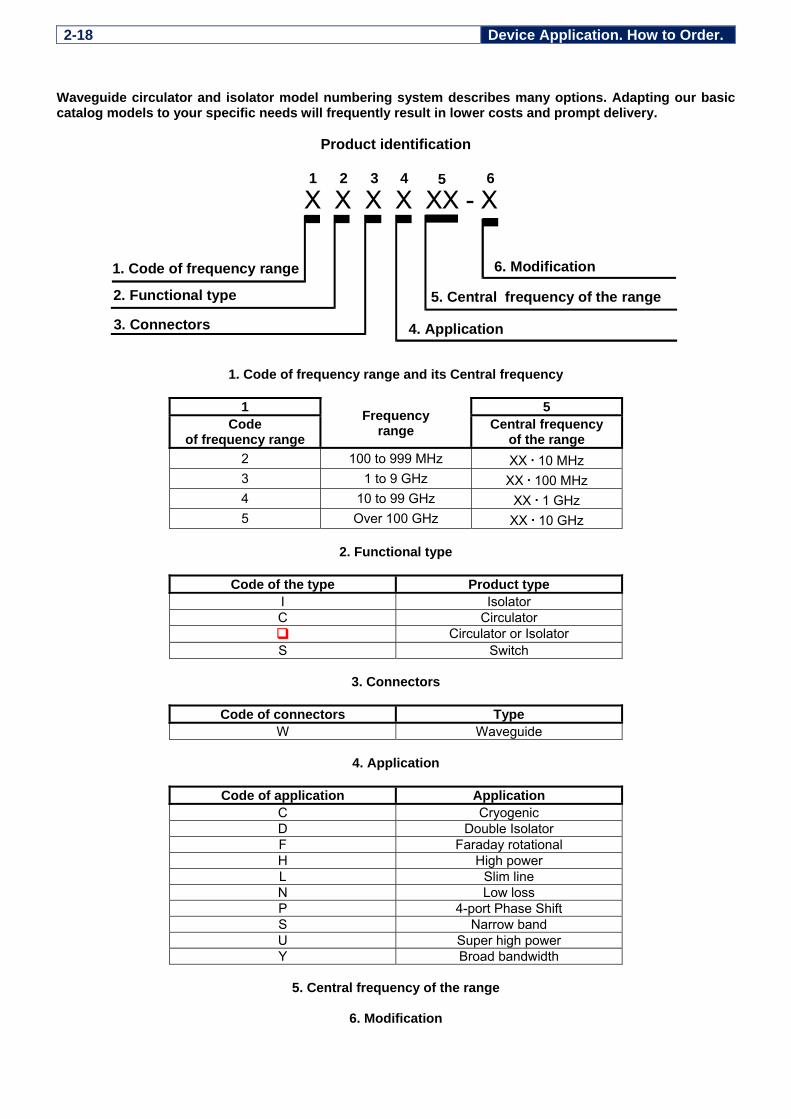
2-18 Device Application. How to Order. Waveguide circulator and isolator model numbering system describes many options. Adapting our basic catalog models to your specific needs will frequently result in lower costs and prompt delivery.
Product identification
1. Code of frequency range and its Central frequency
1 Frequency range
5 Code
of frequency range Central frequency
of the range 2 100 to 999 MHz XX . 10 MHz 3 1 to 9 GHz XX . 100 MHz 4 10 to 99 GHz XX . 1 GHz 5 Over 100 GHz XX . 10 GHz
2. Functional type
Code of the type Product type
I Isolator C Circulator
Circulator or Isolator S Switch
3. Connectors
Code of connectors Type
W Waveguide
4. Application
Code of application Application C Cryogenic D Double Isolator F Faraday rotational H High power L Slim line N Low loss P 4-port Phase Shift S Narrow band U Super high power Y Broad bandwidth
5. Central frequency of the range
6. Modification
X X X X XX - X
1. Code of frequency range
5. Central frequency rangeof the 2. Functional type
3. Connectors
6. Modification
4. Application
1 2 3 4 5 6


![Review Article MicrowaveMagnetoelectricDevices · 2019. 7. 31. · microwave passive devices such as phase shifters, circulators, filters, isolators, and resonators [5, 7]. Depending](https://static.fdocuments.in/doc/165x107/60df3e448d9bcb5f8e4c7c69/review-article-microwavemagnetoelectricdevices-2019-7-31-microwave-passive.jpg)