DC Circuits: First-Order...
31
EENG223: CIRCUIT THEORY I DC Circuits: First-Order Circuits Hasan Demirel
Transcript of DC Circuits: First-Order...

EENG223: CIRCUIT THEORY I
DC Circuits:
First-Order Circuits Hasan Demirel
EENG223: CIRCUIT THEORY I
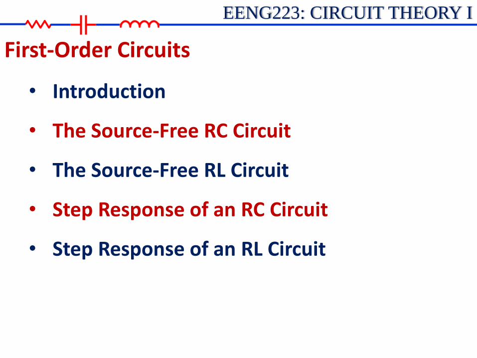
• Introduction
• The Source-Free RC Circuit
• The Source-Free RL Circuit
• Step Response of an RC Circuit
• Step Response of an RL Circuit
First-Order Circuits
EENG223: CIRCUIT THEORY I
• A first-order circuit can only contain one energy storage element (a capacitor or an inductor).
• The circuit will also contain resistance.
• So there are two types of first-order circuits: RC circuit RL circuit
• A first-order circuit is characterized by a first-order differential equation.
First-Order Circuits: Introduction

EENG223: CIRCUIT THEORY I
• A source-free circuit is one where all independent sources have been disconnected from the circuit after some switch action.
• The voltages and currents in the circuit typically will have some transient response due to initial conditions (initial capacitor voltages and initial inductor currents).
• We will begin by analyzing source-free circuits as they are
the simplest type. Later we will analyze circuits that also contain sources after the initial switch action.
First-Order Circuits: The Source-Free Circuits
EENG223: CIRCUIT THEORY I
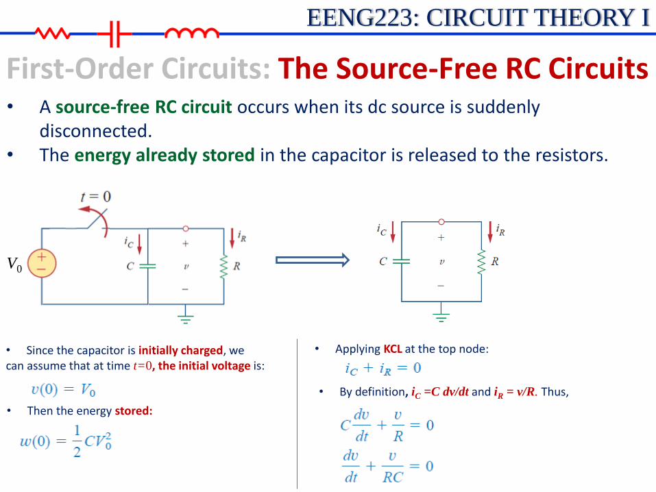
• A source-free RC circuit occurs when its dc source is suddenly disconnected.
• The energy already stored in the capacitor is released to the resistors.
First-Order Circuits: The Source-Free RC Circuits
V0
• Since the capacitor is initially charged, we can assume that at time t=0, the initial voltage is:
• Then the energy stored:
• Applying KCL at the top node:
• By definition, iC =C dv/dt and iR = v/R. Thus,

EENG223: CIRCUIT THEORY I
First-Order Circuits: The Source-Free RC Circuits
V0
• This is a first-order differential equation, since only the first derivative of v is involved.
• Rearranging the terms:
• Integrating both sides:
• ln A is the integration constant. Thus
• Taking powers of e produces:
• From the initial conditions: v(0)=A=V0
• The natural response of a circuit refers to the behavior (in terms of voltages and currents) of the circuit itself, with no external sources of excitation.

EENG223: CIRCUIT THEORY I
• General form of the Differential Equations (DE) and the response for a 1st-order source-free circuit:
First-Order Circuits: The Source-Free RC Circuits
In general, a first-order D.E. has the form:
00)(1
tfortxdt
dx
Solving this DE (as we did with the RC circuit) yields:
0)0()(
tforextx
t
here τ= (Greek letter “Tau”) = time constant(in seconds)

EENG223: CIRCUIT THEORY I
• Notes concerning τ:
First-Order Circuits: The Source-Free RC Circuits
So, for an RC circuit: RC
1) For the Source-Free RC circuit the DE is: 00)(1
tfortvRCdt
dv
2) τ is related to the rate of exponential decay in a circuit as shown below.
3) It is typically easier to sketch a response in terms of multiples of τ than to be concerning with scaling of the graph.
EENG223: CIRCUIT THEORY I
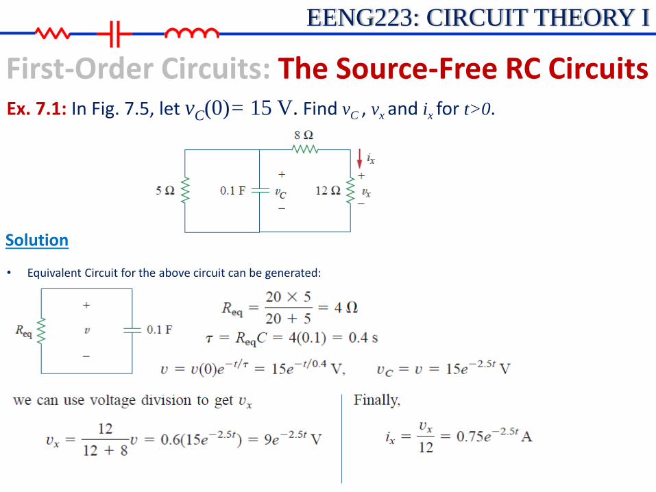
First-Order Circuits: The Source-Free RC Circuits Ex. 7.1: In Fig. 7.5, let vC(0)= 15 V. Find vC , vx and ix for t>0.
Solution
• Equivalent Circuit for the above circuit can be generated:

EENG223: CIRCUIT THEORY I
First-Order Circuits: The Source-Free RC Circuits
• Equivalent Resistance seen by a Capacitor For the RC circuit in the previous example, it was determined that
τ= RC. But what value of R should be used in circuits with multiple resistors?
In general, a first-order RC circuit has the following time constant:
where REQ is the Thevenin resistance seen by the capacitor.
More specifically, REQ = R (seen from the terminals of the capacitor for t>0 with independent sources killed.)
CREQ

EENG223: CIRCUIT THEORY I
First-Order Circuits: The Source-Free RC Circuits Ex. : Refer to the circuit below. Let vC(0)= 45 V. DeterminevC , vx and io for t≥0.
Solution
• Time constant τ :
• Then:
• Consider Req seen from the capacitor.
12818
612eqR
sCReq 43
112
V45)0()( 25.04 t
t
CC eevtv
V15453
1)(
84
4)( 25.025.0 tt
Cx eetvtv
V75.38
4515
8
)()()( 25.0
25.025.0t
tt
Cxo e
eetvtvti
EENG223: CIRCUIT THEORY I
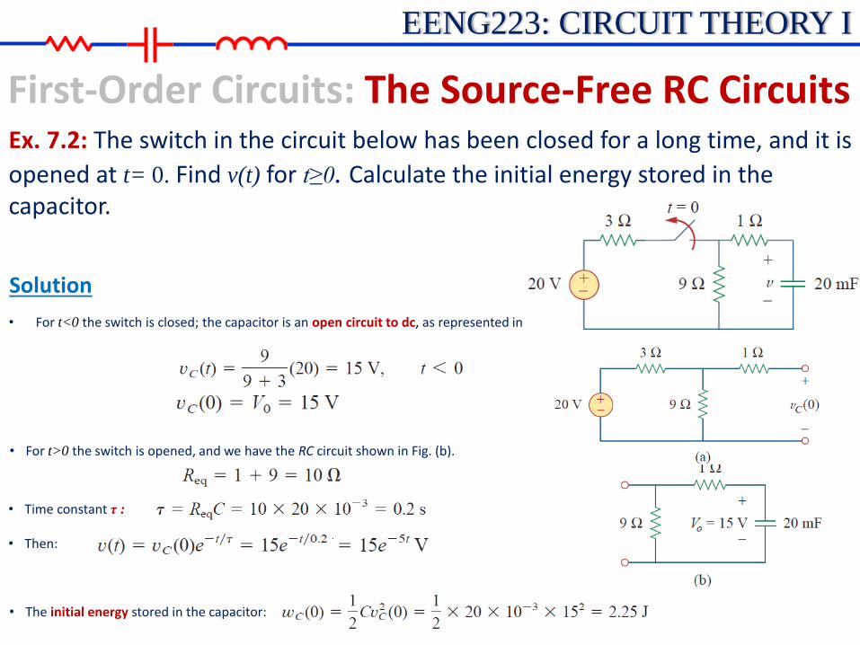
First-Order Circuits: The Source-Free RC Circuits Ex. 7.2: The switch in the circuit below has been closed for a long time, and it is
opened at t= 0. Find v(t) for t≥0. Calculate the initial energy stored in the capacitor.
Solution
• For t<0 the switch is closed; the capacitor is an open circuit to dc, as represented in Fig. (a).
• For t>0 the switch is opened, and we have the RC circuit shown in Fig. (b).
• Time constant τ :
• Then:
• The initial energy stored in the capacitor:

EENG223: CIRCUIT THEORY I
First-Order Circuits: The Source-Free RC Circuits Ex. : If the switch in Fig. below opens at t= 0, find v(t) for t≥0 and wC(0).
Solution
• For t>0 the switch is opened, and we have the RC circuit shown in Fig. (b).
• Time constant τ :
• Then:
• The initial energy stored in the capacitor:
• For t<0 the switch is closed; the capacitor is an open circuit to dc as shown in Fig. (a).
V8)0(
0V82463
3)(
0
Vv
tfortv
C
C
(a)
(b)
316
412eqR
sCReq 5.06
13
V8)0()( 25.0 t
t
C eevtv
J33.5)8(6
1
2
1)0(
2
1)0( 22
CCvwC

EENG223: CIRCUIT THEORY I
First-Order Circuits: The Source-Free RC Circuits Ex. : The switch in the circuit shown had been closed for a long time and then opened at time t = 0.
a) Determine an expression for v(t). b) Graph v(t) versus t. c) How long will it take for the capacitor to
completely discharge? d) Determine the capacitor voltage at time
t=100ms.
e) Determine the time at which the capacitor voltage is 10V.

EENG223: CIRCUIT THEORY I
• A source-free RL circuit occurs when its dc source is suddenly disconnected.
• The energy already stored in the inductor is released to the resistors.
First-Order Circuits: The Source-Free RL Circuits
• At time, t=0 , the intuctor has the initial current:
• Then the energy stored:
• We can apply KVL around the loop above :
• By definition, vL =L di/dt and vR = Ri. Thus,
I0
t=0

EENG223: CIRCUIT THEORY I
First-Order Circuits: The Source-Free RL Circuits
• This is a first-order differential equation, since only the first derivative of i is involved.
• Rearranging the terms and integrating:
• Then:
• Taking powers of e produces:
• Time constant for RL circuit becomes:
The natural response of the RL circuit is an exponential decay of the initial current.
I0
t=0

EENG223: CIRCUIT THEORY I
• General form of the Differential Equations (DE) and the response for a 1st-order source-free circuit:
First-Order Circuits: The Source-Free RL Circuits
In general, a first-order D.E. has the form:
00)(1
tfortxdt
dx
Solving this DE (as we did with the RL circuit) yields:
0)0()(
tforextx
t
Then:
Where:
0)0()( 0
tforeIeiti
tt
R
L

EENG223: CIRCUIT THEORY I
First-Order Circuits: The Source-Free RL Circuits
• Equivalent Resistance seen by an Inductor For the RL circuit , it was determined that τ= L/R. As with the RC circuit,
the value of R should actually be the equivalent (or Thevenin) resistance seen by the inductor.
In general, a first-order RL circuit has the following time constant:
where REQ is the Thevenin resistance seen by the inductor.
More specifically, REQ = R (seen from the terminals of the capacitor for t>0 with independent sources killed.)
EQR
L

EENG223: CIRCUIT THEORY I
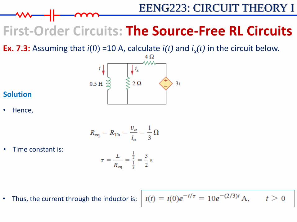
First-Order Circuits: The Source-Free RL Circuits Ex. 7.3: Assuming that i(0) =10 A, calculate i(t) and ix(t) in the circuit below.
Solution
• Substituting Eq. (2) into Eq. (1) gives.
• Thevenin resistance at the inductor terminals. we insert a voltage source with v0=1 V. Applying KVL to the two loops results (1)
(2)
EENG223: CIRCUIT THEORY I
First-Order Circuits: The Source-Free RL Circuits Ex. 7.3: Assuming that i(0) =10 A, calculate i(t) and ix(t) in the circuit below.
Solution
• Time constant is:
• Hence,
• Thus, the current through the inductor is:
EENG223: CIRCUIT THEORY I
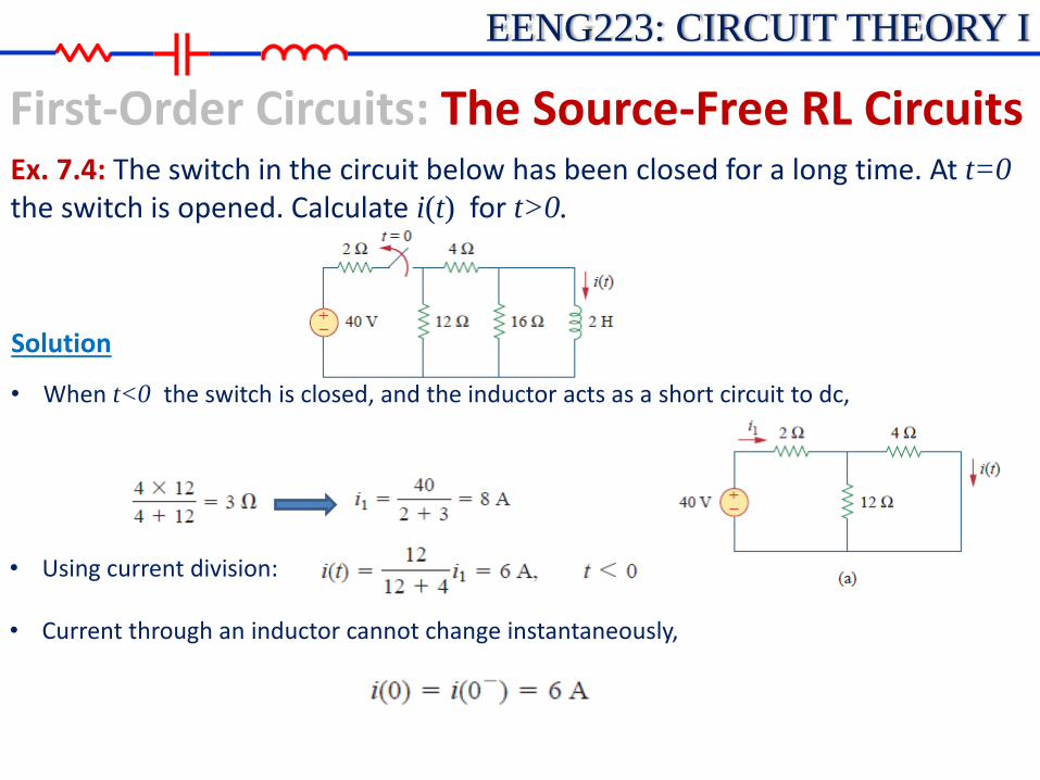
First-Order Circuits: The Source-Free RL Circuits Ex. 7.4: The switch in the circuit below has been closed for a long time. At t=0
the switch is opened. Calculate i(t) for t>0.
Solution
• When t<0 the switch is closed, and the inductor acts as a short circuit to dc,
• Using current division:
• Current through an inductor cannot change instantaneously,

EENG223: CIRCUIT THEORY I
First-Order Circuits: The Source-Free RL Circuits Ex. 7.4: The switch in the circuit below has been closed for a long time. At t=0
the switch is opened. Calculate i(t) for t>0.
Solution
When t>0 the switch is open and the voltage source is disconnected. We now have the source-free RL circuit in Fig. (b).
• The time constant is :
• Thus,

EENG223: CIRCUIT THEORY I
First-Order Circuits: The Source-Free RL Circuits Ex. : Determine an expression for i(t). Sketch i(t) versus t.

EENG223: CIRCUIT THEORY I
First-Order Circuits: Step Response of an RC Circuit
• Step Response (DC forcing functions) • Consider circuits having DC forcing functions for t > 0 (i.e., circuits that have
independent DC sources for t > 0).
• The general solution to a differential equation has two parts: • x(t) = xh+ xp = homogeneous solution + particular solution • or • x(t) = xn+ xf = natural solution + forced solution
• xn is due to the initial conditions in the circuit • and xf is due to the forcing functions (independent voltage and current
sources for t > 0).
• xf in general take on the “form” of the forcing functions, • So DC sources imply that the forced response function will be a constant(DC), • Sinusoidal sources imply that the forced response will be sinusoidal, etc.
EENG223: CIRCUIT THEORY I
First-Order Circuits: Step Response of an RC Circuit
• Step Response (DC forcing functions) • Since we are only considering DC forcing functions in this chapter, we assume
that : xf = B (constant). • Recall that a 1st-order source-free circuit had the form Ae-t/τ. Note that there
was a natural response only since there were no forcing functions (sources) for t > 0. So the natural response was
0/ tforAex t
n
• The complete response for 1st-order circuit with DC forcing functions therefore will have the form: x(t) = xf + xn
/)( tAeBtx
• The “Shortcut Method”: An easy way to find the constants B and A is to evaluate x(t) at 2 points. Two convenient points at t = 0 and t = ∞ since the circuit is under dc conditions at these two points. This approach is sometimes called the “shortcut method.”
EENG223: CIRCUIT THEORY I
First-Order Circuits: Step Response of an RC Circuit
• Step Response (DC forcing functions) • The “Shortcut Method” :
So, x(0) = B + Ae0= B + A And x(∞) = B + Ae-∞= B
• Complete response yields the following expression:
/)]()0([)()( texxxtx
• The Shortcut Method- Procedure: The shortcut method will be the key method used to analyze 1st-order circuit with DC forcing functions:
1. Analyze the circuit at t = 0-: Find x(0-) = x(0+)
2. Analyze the circuit at t = ∞: Find x(∞) 3. Find τ= REQC or τ= L/REQ
4. Assume that x(t) has the form x(t) = x(∞)+[x(0) –x(∞)] e-t/τ using x(0) and x(∞)

EENG223: CIRCUIT THEORY I
First-Order Circuits: Step Response of an RC Circuit
• Step Response (DC forcing functions)
Notes: The “shortcut method” also works for source-free circuits, but x(∞) = B=0
since the circuit is dead at t = ∞. If variables other than vC or iL are needed, it is generally easiest to solve for vC or iL first and then use the result to find the desired variable.

EENG223: CIRCUIT THEORY I
First-Order Circuits: Step Response of an RC Circuit Ex. 7.10: The switch in Fig. Below has been in position A for a long time. At t=0
the switch moves to B. Determine v(t) for t>0 and calculate its value at t =1 s and 4 s.
Solution
• Voltage across the capacitor just before t=0. Capacitor is open circuit under dc conditions:
• Capacitor voltage cannot change instantaneously:
• For t>0 (switch to B). Thevenin Resistance connected to the capacitor:
• Time constant:

EENG223: CIRCUIT THEORY I
First-Order Circuits: Step Response of an RC Circuit Ex. 7.10: The switch in Fig. below has been in position A for a long time. At t=0
the switch moves to B. Determine v(t) for t>0 and calculate its value at t 1 s and 4 s.
Solution
• Since the capacitor acts like an open circuit to dc at steady state, v(∞) = 30 V. Thus,
EENG223: CIRCUIT THEORY I
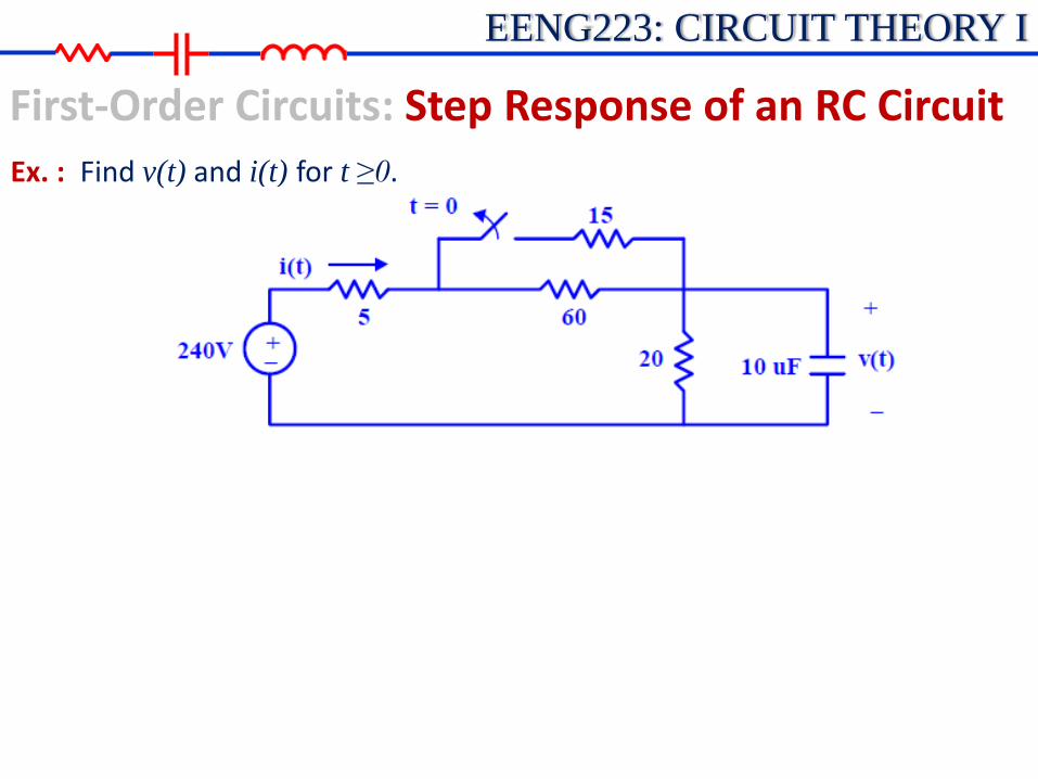
First-Order Circuits: Step Response of an RC Circuit
Ex. : Find v(t) and i(t) for t ≥0.
EENG223: CIRCUIT THEORY I
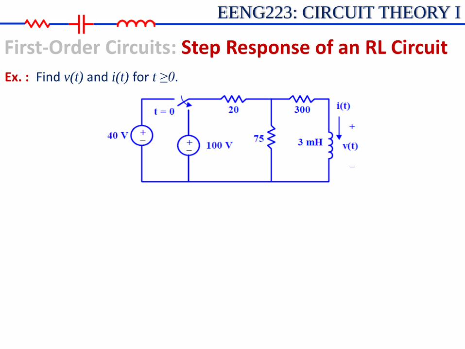
First-Order Circuits: Step Response of an RL Circuit
Ex. : Find v(t) and i(t) for t ≥0.