R&D at RWTH Aachen towards DC-DC Conversion Powering Schemes for the CMS Tracker at SLHC
DC-616 Instruction Manual - CMS Colorado Mailing and...
96
Transcript of DC-616 Instruction Manual - CMS Colorado Mailing and...


i
Thank you for your purchase of the DC-616.To ensure safe and effi cient prolonged use of this machine, read and thoroughly understand this manual before using the machine.After using this manual, be sure to keep it in a handy place to reference.
Pictorial Symbols and Other Notations Used in This Manual
(→ P.00 “xxxx”)
The English version of DC-616 Instruction Manual is the original instructions.
Trademarks● Microsoft, Windows, Windows NT, and Windows Vista are either registered trademarks or
trademarks of Microsoft Corporation in the United States and/or other countries. All other company names and product names shown in this manual are trademarks or registered trademarks of their respective companies.
PLEASE NOTEIn the interests of upgrading our product, specifi cations and other data given in this manual are subject to change without notice.If the manual contains anything that you do not understand, contact the dealer for clarifi cation.
Introduction
: Introduces instructions for correct operation of the machine. If these instructions are ignored, the machine may not be able to operate at optimum performance or may break down.
: Introduces information that is useful for operation and maintenance of the machine, or information about the machine’s performance, etc.
: Indicates the page number and item containing related information.
IMPORTANT
REFERENCE

ii
DECLARATION OF CONFORMITY
For EU
Duplo Seiko Corporation, located at 353, Koudai, Kinokawa-shi, Wakayama 649-6551, Japan, declares that the product (or products)
Duplo International Ltd, Sandown Industrial Park, Mill Road, Esher, Surrey, KT108BL, United KingdomEn
KONFORMITÄTSERKLÄRUNG
Inhaber der technischen Datei in der Europäischen Gemeinschaft:
Duplo International Ltd, Sandown Industrial Park, Mill Road, Esher, Surrey, KT108BL, United KingdomGe
DECLARATION DE CONFORMITEDuplo Seiko Corporation, dont le siège est situé au 353, Koudai, Kinokawa-shi, Wakayama 649-6551, Japon, déclare que le ou les produits
Dépositaire du dossier technique auprès de la Communauté européenne :
Duplo International Ltd, Sandown Industrial Park, Mill Road, Esher, Surrey, KT108BL, United KingdomFr
DICHIARAZIONE DI CONFORMITÁDuplo Seiko Corporation, sita a 353, Koudai, Kinokawa-shi, Wakayama 649-6551, Giappone, dichiara che il prodotto (o i prodotti) è/sono
Responsabile della documentazione tecnica all’interno della Comunità Europea:
Duplo International Ltd, Sandown Industrial Park, Mill Road, Esher, Surrey, KT108BL, United KingdomIt
DECLARACIÓN DE CONFORMIDADDuplo Seiko Corporation, con domicilio en 353, Koudai, Kinokawa-shi, Wakayama 649-6551, Japón, declara que el producto (o los productos) cumple con las disposiciones previstas en los reglamentos. Seguidamente se indica la tabla de referencia.
Depositario del archivo técnico en la Comunidad Europea:
Duplo International Ltd, Sandown Industrial Park, Mill Road, Esher, Surrey, KT108BL, United KingdomSp
Low Voltage Directive 2006/95/EC
Machinery Directive 2006/42/EC
Electromagnetic Compatibility Directive 2004/108/EC
Restriction of Hazardous Substances Directive 2011/65/EU
Niederspannungsrichtlinie 2006/95/EG
Maschinenrichtlinie 2006/42 EG
Richtlinie 2004/108/EG zur elektromagnetischen Verträglichkeit
Directive 2006/95/CE relative au matériel électrique destiné à être employé dans certaines limites de tension
Directive 2006/42/CE relative aux machines
Directive 2004/108/CE concernant la compatibilité électromagnétique
Directive 2011/65/UE relative à la limitation de l’utilisation de certaines substances dangereuses
Direttiva 2006/95/CE relativa alle apparecchiature a bassa tensione
Direttiva 2006/42/CE sui macchinari
Direttiva 2004/108/CE di compatibilità elettromagnetica
Direttiva 2011/65/UE sulla restrizione dell'uso di sostanze pericolose
Directiva 2006/95/CE sobre baja tensión
Directiva 2006/42/CE sobre máquinas
Directiva 2004/108/CE sobre compatibilidad electromagnética
Die Duplo Seiko Corporation mit Sitz in 353, Koudai, Kinokawa-shi, Wakayama 649-6551 Japan, erklärt hiermit, dass das Produkt (oder die
Directiva 2011/65/UE de restricción de sustancias peligrosas

iii
Disposal of Old Electrical & Electronic EquipmentThis symbol (the symbol of the crossed out wheeled bin) indicates that in European countries this product should not be disposed of as household waste.Please recycle where facilities exist by checking with your local authority or supplier for recycling advice.By ensuring this product is disposed of correctly through proper treatment, recovery and recycling, you will help prevent potential negative effects on the environment and human health.
En
Entsorgung von alten elektrischen und elektronischen AusrüstungsteilenDieses Symbol (das Symbol mit dem durchgekreuzten fahrbaren Müllbehälter) zeigt an, dass dieses Produkt in europäischen Länden nicht als Haushaltsmüll entsorgt werden darf. Bitte informieren Sie sich bei Ihren örtlichen Behörden oder bei Ihrem Händler hinsichtlich einer Empfehlung für die Entsorgung und führen Sie die betreffenden Teile dort, wo solche Einrichtungen vorhanden sind, einem Recycling-Prozess zu. Indem sie sicherstellen, dass das betreffende Produkt durch richtige Behandlung, Rückführung und Recycling entsorgt wird, tragen Sie dazu bei, möglichen negativen Auswirkungen auf die Umwelt und die menschliche Gesundheit vorzubeugen.
Ge
Elimination du matériel électronique et électrique usagéCe symbole (une poubelle marquée d’une croix) indique que dans les pays européens, ce produit ne doit pas être éliminé comme des ordures ménagères.Recyclez-le dans les sites adaptés qui vous seront indiqués par les autorités locales ou renseignez-vous auprès de votre fournisseur.En veillant à ce que ce produit soit éliminé correctement avec un traitement, une collecte et un recyclage adaptés, vous contribuez à éviter son action nocive potentielle sur l’environnement et la santé humaine.
Fr
Smaltimento di attrezzature elettriche ed elettroniche consumateQuesto simbolo (il simbolo della pattumiera con rotelle barrata) indica che nei paesi
Per favore smaltire in luogo addetto al riciclo, dove esistente, chiedendo informazioni alle autorità locali o a chi fornisce consulenza a proposito.Garantendo uno smaltimento adeguato di questo prodotto (trattamento, recupero e riciclo corretto), aiuterete a prevenire effetti negativi sull’ambiente e sulla salute dell’uomo.
It
Eliminación de residuos de aparatos eléctricos y electrónicosEste símbolo (un cubo de basura tachado) indica que en los países europeos este producto no deberá eliminarse como si se tratara de un residuo doméstico. Solicite asesoramiento sobre reciclaje a las autoridades locales o a su distribuidor, y siga la normativa en materia de gestión medioambiental y reciclaje de este tipo de residuos. Si toma las medidas pertinentes para que este producto se elimine mediante un tratamiento, recuperación y reciclaje adecuados, contribuirá a evitar posibles efectos negativos en el medio ambiente y la salud humana.
Sp

iv
A circle with a line through it indicates a prohibited action.The particular act prohibited is indicated by a picture inside the circle.(In the example shown here, the prohibited act is disassembly.)
A black disc indicates an instruction, or sometimes a prohibited action.The instruction itself is indicated by pictorial symbols drawn in white on the disc. (In the example shown here, the instruction is “Remove the plug from the outlet”.)
Notes on Safety (Please Read and Observe)
Various symbols and pictures are used in this manual and on the labels affi xed to the machine.These symbols and pictures provide warnings and instructions to prevent danger to you or other person, and to prevent damage to offi ce property.The meanings of these symbols and pictures are explained below.
Indicates a high degree of potential danger. Failure to heed the warning may lead to death or serious injury.
Indicates a medium degree of potential danger. Failure to heed the caution may lead to injury or damage to property.
<Examples of Pictorial Symbols>
WARNING
CAUTION
● If the machine is used after foreign matter (metal fragments, water, or liquid) has entered the machine, this may result in fi re or electric shock.
→ Turn the main unit’s power switch OFF, and then remove the power plug from the outlet. Contact the sales distributor.
● If the machine is used after heat, smoke, a strange smell, or other abnormality has been detected, this may result in fi re or electric shock.
→ Turn the power switch OFF, and then remove the power plug from the outlet. Contact the sales distributor.
● Do not insert or drop metal, fl ammable material, or any other materials through the ventilation holes into the interior of the machine.
→ Doing so may result in fi re or electric shock.
● Keep the machine away from a pin, wire, or other metallic or foreign objects.Do not allow liquid to enter the machine through its openings or gaps.
→ Malfunctions and a fi re or electric shock may result.
● Do not place fl ower vases, fl owerpots, cups, or water containers (including metal containers) on top of the machine.
→ Fire or electric shock may result if liquid spills inside the machine.
WARNING
● Precautions for Use
Safety Precautions

v
Notes on Safety (Please Read and Observe)
● Caution for Grounding
● Use only the power cord that is provided among the accessories. Insert the power cord plug fi rmly into the socket, so that proper electrical contact is effected.
→ Use of any other power cord could result in imperfect grounding.If grounding is imperfect and electrical leakage occurs, fi re or electric shock could result.
WARNING
● Caution for Power Supply and Power Cord
● Use only the power cord that is provided among the accessories. The power cord is only for this product. Never use it for another product.
● Do not use a source voltage other than that specifi ed.Do not connect two or more loads to a single outlet.
→ Doing so may result in fi re or electric shock.
● Do not remove or insert the power plug with wet hands.→ Doing so may result in electric shock.
● Do not damage, break, or modify the power cord.Do not place heavy objects on, tug or bend it unnecessarily.
→ Doing so may result in fi re or electric shock.
● Remove the power plug itself, not the cord.→ Tugging the cord may damage it (expose conductors, or cause disconnections,
etc.), resulting in fi re or electric shock.
● Be sure to remove dust from the power plug and/or the outlet.Using these without removing dust may have minute electric current fl ow to the surface due to the humidity and cause a fi re due to the heat.
→ It may cause a fi re or electric shock.
WARNING
vi
Notes on Safety (Please Read and Observe)
WARNING
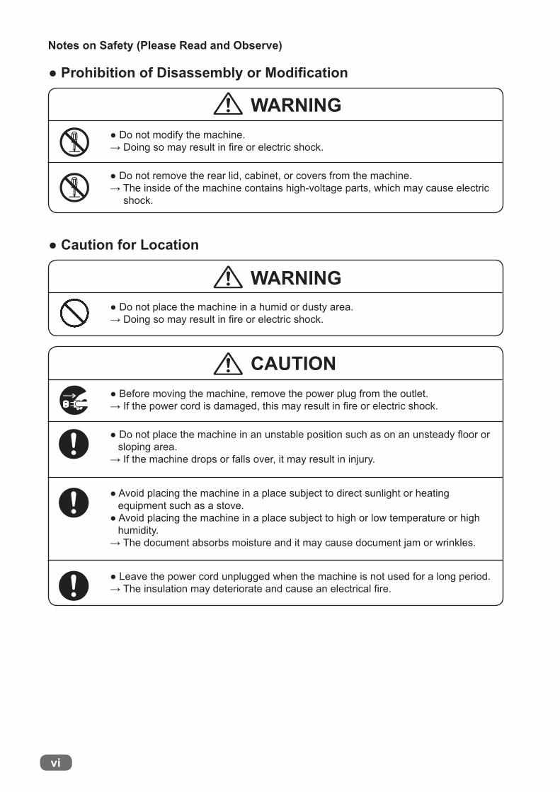
● Prohibition of Disassembly or Modifi cation
● Do not modify the machine.→ Doing so may result in fi re or electric shock.
● Do not remove the rear lid, cabinet, or covers from the machine.→ The inside of the machine contains high-voltage parts, which may cause electric
shock.
WARNING
● Caution for Location
● Do not place the machine in a humid or dusty area.→ Doing so may result in fi re or electric shock.
CAUTION● Before moving the machine, remove the power plug from the outlet.→ If the power cord is damaged, this may result in fi re or electric shock.
● Do not place the machine in an unstable position such as on an unsteady fl oor or sloping area.
→ If the machine drops or falls over, it may result in injury.
● Avoid placing the machine in a place subject to direct sunlight or heating equipment such as a stove.
● Avoid placing the machine in a place subject to high or low temperature or high humidity.
→ The document absorbs moisture and it may cause document jam or wrinkles.
● Leave the power cord unplugged when the machine is not used for a long period.→ The insulation may deteriorate and cause an electrical fi re.

vii
Notes on Safety (Please Read and Observe)
CAUTION
● Caution for Cleaning
● Before cleaning the machine, turn off the power switch and unplug the power cord.
→ If the machine is activated accidentally, it may cause injury.
● Do not use fl ammable sprays or solvents inside or near the machine.→ Gas may accumulate inside the machine causing a fi re or explosion.
● Preventing Injury to Hands or Fingers
● The optional perforation unit contain uncovered tools. Keep your hands or fi ngers off inside those.
● Use tweezers or a similar tool to remove jammed document.Be sure to unplug the power cord before removing jammed document in order to prevent an electric shock.
● Caution for Installation
WARNING
WARNING
● The machine must be installed by service person only.→ If you want to change installation location, contact your service person.
(Changing location requires precise adjustment.)
● Once the machine is in position, secure in place using the casters.→ If the machine falls over, this could result in personal injury.
WARNING

viii
Notes on Safety (Please Read and Observe)
WARNING Cutters and movable parts are inside this cover.
Before opening the cover to work,unplug the power cord.Use caution when working near cuttersand movable parts.
WARNINGDo not touchblade!
WARNINGDo not touchblade!
WARNINGDo N OT put hands inside machinewhile it is ope rating.
Hands could get caught upor c rushed.
WARNING Cutters and movable parts are inside this cover.Before opening the cover to work,unplug the power cord.Use caution when working near cuttersand movable parts.
Locations of Warning LabelsKeep the WARNING and CAUTION labels clean at all times.If labels become damaged or come off, contact your service person.
No. Part No. Name Q'ty1 L8-T108* WARNING LABEL 22 S2-T105* WARNING LABEL 63 M7-T303* WARNING LABEL 24 S2-T115* WARNING LABEL 2
1
2
2
3
41

ix
Notes on Safety (Please Read and Observe)
No. Part No. Name Q'ty5 R7-T115* WARNING LABEL 1
5

x
Notes on Safety (Please Read and Observe)
Interlock System for Safety
No. Name Equipment for safety
1 Top cover The DC-616 stops running when the interlock switch detects the cover opened.
2 Front cover The DC-616 stops running when the interlock switch detects the cover opened.
3 Perforation unit installing position
The DC-616 stops running when the interlock switch detects the perforation unit removed or the cover opened.
● What is the interlock system for safety?It is the function for keeping you safety and for avoiding any danger operations or situations by the limitation of operation which may cause a damage to the machine or other surrounding facilities.The DC-616 is equipped with various safety functions for the case of causing any danger operations or situations, and it stops running the operation in that cases.
31
2

xi
Notes on Safety (Please Read and Observe)
Machine Dimensions and Required Space for Operation

xii
Chapter 2
Chapter 1
Contents
Introduction ............................................................................ i Notes on Safety (Please Read and Observe) .................................... iv
Safety Precautions ............................................................. ivLocations of Warning Labels .................................................viiiInterlock System for Safety ....................................................x● What is the interlock system for safety? ..................................xMachine Dimensions and Required Space for Operation ............... xi
Before Using This Machine
Part Names and Their Functions ....................................................2Appearance .......................................................................2Appearance (Feed Side) .......................................................3Appearance (Ejection Side) ....................................................4Inside ...............................................................................5Control Panel .....................................................................6LCD Panel ........................................................................7
Turning Power ON/OFF ...............................................................8Turning Power ON ...............................................................8Turning Power OFF .............................................................9
Preparation Before Use ............................................................. 10Loading Documents ........................................................... 10Setting the Exit Tray ........................................................... 11Installing the Perforation Unit ............................................... 11Removing the Perforation Unit .............................................. 13Change the Perforation Tool Position ...................................... 14Change the Perforation Tool Depth ......................................... 15Attaching the Card Stacker .................................................. 16Adjusting the Card Stacker Guides ......................................... 17
How to Connect the DC-616 to Your Computer .................................. 19Before Preparing Document ........................................................ 20
Defi nition of Programming Terms ........................................... 21Limit of Trail Cutting ........................................................... 27
Programming JOB on Control Panel
Before Programming JOB ........................................................... 30Programming a JOB on the Control Panel ........................................ 31Programming a New JOB (Advanced Mode) ..................................... 33Programming a New JOB (Simple Mode) ......................................... 39Changing the Stored JOB ........................................................... 41

xiii
Chapter 6
Chapter 3
Chapter 4
Chapter 5
Contents
Basic Operations
Processing Documents by Selecting a JOB ......................................44Function Setting ......................................................................46Setting Functions .....................................................................47Automatic Setup Using Barcodes ..................................................52Adjusting Feeder .....................................................................54
Elevator level (Feed tray) .....................................................54Separator ........................................................................54Airfl ow ............................................................................54Skew Compensation ..........................................................55
Adjusting for Using a Light Weight Document ....................................56Adjusting the amount of the air fl ow (Shutter) ............................56
Troubleshooting
When Messages Appear ............................................................58When a Paper Jam Has Occurred .................................................63
Example: J3 Feed error .......................................................63Example: J7 WASTE BOX ...................................................64
Daily Maintenance
Daily Maintenance ...................................................................66Cleaning the Slitter Tool ......................................................66Cleaning the Conveyance Rollers ..........................................67Cleaning the Skew Correction Belt .........................................68
Waste Box .............................................................................69
Specifi cations
Specifi cations .........................................................................72
Appendix
Index ...................................................................................76


1
Chapter 1
Before U
sing This Machine
1Before Using This Machine
This chapter contains essential information you should understand such as how to set up the system, the names of the machine parts, etc.
Part Names and Their Functions ............................................................ 2Appearance ................................................................................. 2Appearance (Feed Side) ................................................................. 3Appearance (Ejection Side) .............................................................. 4Inside ......................................................................................... 5Control Panel ............................................................................... 6LCD Panel .................................................................................. 7
Turning Power ON/OFF ........................................................................ 8Turning Power ON ......................................................................... 8Turning Power OFF ....................................................................... 9
Preparation Before Use .......................................................................10Loading Documents ......................................................................10Setting the Exit Tray ......................................................................11Installing the Perforation Unit ..........................................................11Removing the Perforation Unit .........................................................13Changing the Perforation Tool Position ...............................................14Change the Perforation Tool Depth ....................................................15Attaching the Card Stacker .............................................................16Adjusting the Card Stacker Guides ....................................................17
How to Connect the DC-616 to Your Computer ..........................................19Before Preparing Document .................................................................20
Defi nition of Programming Terms ......................................................21Limit of Trail Cutting ......................................................................27

2
Part Names and Their Functions
Appearance
No. Name Function1 Control panel Displays operations and status.2 Exit tray Receives the fi nished products.3 Waste box Receives pieces of waste paper.4 Front cover Open this to remove the waste box. 5 Feed tray Original document is placed here.6 Scale Measures the cut and slit position, and the fi nished product.7 Top cover Open this to remove the paper jam.
1
2
3
4
5
67
2
3
Part Names and Their Functions
Before U
sing This Machine
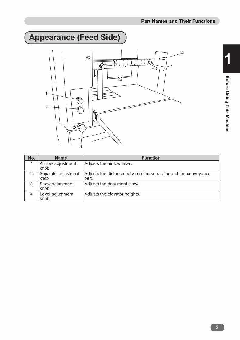
1Appearance (Feed Side)
No. Name Function1 Airfl ow adjustment
knobAdjusts the airfl ow level.
2 Separator adjustment knob
Adjusts the distance between the separator and the conveyance belt.
3 Skew adjustment knob
Adjusts the document skew.
4 Level adjustment knob
Adjusts the elevator heights.
1
2
3
4

4
Part Names and Their Functions
Appearance (Ejection Side)
No. Name Function1 Perforation unit
(Optional on 115V model and 230V Asia model)
Perforates parallel to the document feed direction.
2 Side guide Receives the processed documents.3 Back guide Receives the processed documents.4 USB terminal Used for the connection to your computer on PC Controller using.5 AC inlet Connect the power cord here.6 Power switch Press to switch the power on and off.
5
4
3
21
6

2
5
Part Names and Their Functions
Before U
sing This Machine
1Inside
No. Name Function1 Double feed detection
(Optional on 115V model and 230V Asia model)
Detects double feed by ultrasonic sensor.
2 CCD (Optional on 115V model and 230V Asia model)
Reads REG mark/Barcode.
3 Slitter module 1,2 Cuts side margins parallel to the document feed direction. 4 Slitter module 3,4 Cuts parallel to the document feed direction. 5 Slitter module 5,6 Cuts parallel to the document feed direction.6 Gutter defl ector Drops the margin cut off by the slitters into the waste box.7 Cutter module Cuts perpendicularly to the document feed direction.8 Creaser module Creases perpendicularly to the document feed direction.
3 2 18 4567
3456

6
Part Names and Their Functions
Control Panel
No. Name Function
1 LCD panel Displays the status of the machine.Displays the message when an error or paper jam occurs.
2 F key Switches to function selecting screen.3 RETURN key Switches to the previous screen.
4 CURSOR (Left/Right) key Press to move the cursor to the left or right.
5 CURSOR (Up/Down) key Press to the cursor in a lower or an upper direction.
6 SET key Press to set selection/entry.
7 JOG (Forward/Backward) key
Press to eject the document from the machine when paper jam occurred.
8 TEST key
One (sheet) document is processed to test to the current JOB details. When the card stacker is installed, if you press and hold the TEST key for guide adjustment, the processed document temporarily stops. Then, when you press the START key or the TEST key, the processed document is ejected.
9 START keyPress to start processing documents. The START key light turns green when when the machine is ready to process the document in this machine. The machine is inactive when the light is red. In this case, the machine may be running or having an error.
10 STOP key Press to return the current screen to the main screen or to stop processing
No. Name Function1 NUMERIC key Press to enter JOB/values during manual programming.2 SET key Press to set selection/entry.3 CLEAR key Press to clear the count. Press to cancel manual programming.
1
2 3
4
5 6
7 8
9 10
1
2
1
3

2
7
Part Names and Their Functions
Before U
sing This Machine
1LCD Panel
No. Name Function1 Retrieve JOB Retrieves saved JOB.2 Enter JOB Enters and changes JOB.3 Settings Changes functions of the machine.4 Cleaning mode Retrieves Cleaning mode to clean conveyance belt / conveyance
roller.5 Return Returns to standby screen.
● “Select menu” screen
● Standby screen
No. Name Function1 JOB No. Displays the JOB number currently selected.2 JOB name Displays the JOB name currently selected.
3 Counter Displays the number of document sheets processed with the JOB currently set.
4
Function setting AC: Auto cut REG: REG mark BC: BARCODE%
AC is displayed when “Auto cut” is enabled.REG is displayed when “REG mark reading” is enabled.BC is displayed when “Barcode reading” is enabled.% is displayed when “Apply shrinkage” is enabled. is displayed when “Adjust all” is enabled.
is displayed when the PC Controller is online.
Select menu Select menuRetrieve JOBEnter JOBSettings
SettingsCleaning modeReturn
123
45
3
1
4
2
3

8
Connect the “female plug” of the power cord to the “Inlet”.
Turning Power ON
Turning Power ON/OFF
Male plug of the power cord
Outlet
Press the “I” side of the power switch to turn on the power.Model name of this machine appears on the LCD panel and warming-up stats.
Connect the “male plug” of the power cord to the “outlet”.
● Insert the power cord plug securely, so that proper electrical contact is effected. If grounding is imperfect and electrical leakage occurs, fi re or electric shock could result.
WARNING
● Use an access-friendly outlet so that an operator easily plugs and unplugs the power cord after installation.
WARNING
● Unplug the power cord when emergency situation.
WARNING
InletFemale plug of the power cord

2
9
Turning Power ON/OFF
Before U
sing This Machine
1 Turning Power OFF
Press the “○” side of the power switch.The power turns off and display on the LCD panel disappears.

10
Preparation Before Use
Loading DocumentsLoosen the stack of the documents by fl ipping through the sheets and align them.
Load the documents on the feed tray and gently push them toward the inside of the machine.
Adjust the “feed guide” according to the document size and secure it with the “fi xing screw”.
Lever
Set the back guide according to the document.
IMPORTANTThe height of the document stack should not exceed the “MAX” level.
Feed guide
Document
Fixing screw
Back guide

2
11
Preparation Before Use
Before U
sing This Machine
1 Setting the Exit Tray
As shown in the right fi gure, lift the exit tray.There are three setting positions of the exit tray.
IMPORTANTWhen the fi nished document size is A3 or longer, or if the fi nished documents are adhered on the tray due to static electricity, set the exit tray in the downward position.
Attach the back guide and side guides.
Loosen the thumbscrew to remove the “cover” on the ejection side of the DC-616.
Loosen the two thumbscrews on both sides of the “perforation unit”.
Installing the Perforation Unit The perforation unit is optional on 115V model and 230V Asia model.

12
Preparation Before Use
Move the perforation tool assys.(See → P.14 “Changing the Perforation Tool Position”)
Adjust the depth of the perforation tool.(See → P.15 “Changing the Perforation Tool Depth”)
Tighten the two thumbscrews loosened in step 2.
Install the “perforation unit” on the ejection side of the DC-616 by tightening the two perforation unit installing screws..
Select a JOB containing perforation process and perform a test run for one sheet.
Check the processed positions on the fi nished product.When you change the perforation positions, repeat steps 2 to 7.
2
13
Preparation Before Use
Before U
sing This Machine
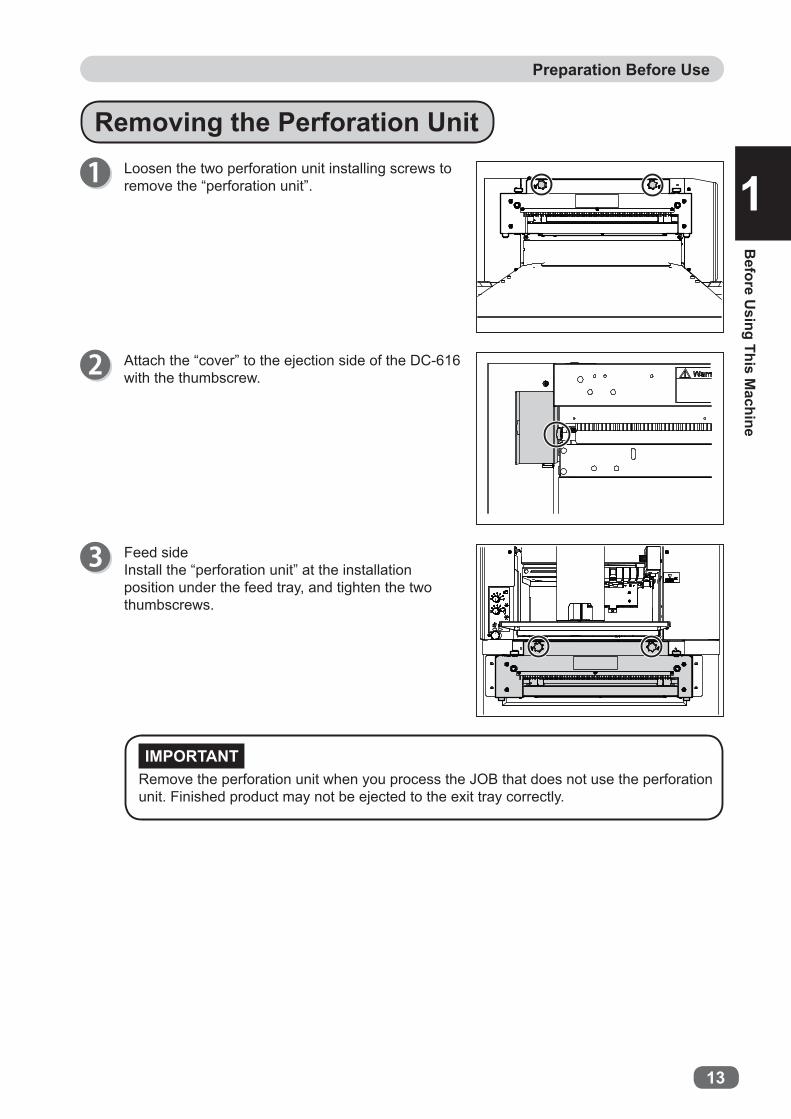
1 Removing the Perforation Unit
IMPORTANT
Loosen the two perforation unit installing screws to remove the “perforation unit”.
Attach the “cover” to the ejection side of the DC-616 with the thumbscrew.
Feed sideInstall the “perforation unit” at the installation position under the feed tray, and tighten the two thumbscrews.
Remove the perforation unit when you process the JOB that does not use the perforation unit. Finished product may not be ejected to the exit tray correctly.

14
Preparation Before Use
REFERENCE
Do not touch the perforation tools.This could result in injury.
WARNING
IMPORTANT
Inside of the perforation unit.Loosen the two hexagon socket set screws each of the two perforation tool assys (each side). (upper tool: 1 pce., lower tool: 1 pce.) Loosen the two hexagon socket set screws each of the three roll assys. (upper roll: 1 pce., lower roll: 1 pce.)
When the hexagonal socket set screw does not face toward you, rotate the shaft as shown in the right fi gure to change the direction.
Move each perforation tool assy to the position where you want to perforate with your fi ngers.
Changing the Perforation Tool PositionRoll assyUpper rollUpper tool
Perforation tool assy
Lower rollLower toolLoosen the hexagon socket set screws which suit the supplied hexagon wrench size.
REFERENCE
Move the “roll assy” to the center and the both sides of the document.
Position adjustment of the roll assys may need depending on the document thickness and JOB type.
Roll assyRoll assyRoll assyPerforation tool assy Perforation tool assy

2
15
Preparation Before Use
Before U
sing This Machine
1
REFERENCE
Perforation tool assyUpper tool
Lower tool
Changing the Perforation Tool Depth
When you change the depth of perforations, loosen the thumbscrew.After adjustment is complete, tighten the thumbscrew.
Tighten the 10 hexagon socket set screws loosened in step 1.
Adjust the perforation toll depth by turning the “depth adjustment screws” on the both sides of the perforation unit.Turn the screw clockwise: The upper tool raises.Turn the screw counterclockwise: The upper tool lowers.Adjust the depth of the perforation tools on both sides.Perform a test run to check the depth of the upper tools on the fi nished product.

16
Preparation Before Use
Place the card stacker on the exit tray along the ejection side of the DC-616.
REFERENCEWhen the perforation unit is installed, place the card stacker along the perforation unit.
REFERENCE
Attaching the Card StackerSet the exit tray horizontally.
Perforated documents become as shown in the right fi gure and stacking capacity may decrease.
The card stacker is optional on 230V Asia model.

2
17
Preparation Before Use
Before U
sing This Machine
1
REFERENCEThe number of the side guides of the card stacker can be changed according to the number of cards per document.
REFERENCE
Adjusting the Card Stacker GuidesSelect a JOB that uses the card stacker, and press and hold the TEST key. The fi nished product stops at the exit before being ejected. Slide each side guide to the ejected position of the fi nished product.
(A)
Adjust the side guide so that the side edge of the fi nished product comes into contact with the “side guide. This adjustment can stack the short fi nished products properly.
1. Loosen the thumbscrew to slide the “stopper”.
2. Remove or attach the “side guides” according to the JOB which you select.
The right fi gure shows front view of (A) in step 1.

18
Preparation Before Use
Press the STOP key to eject the document and adjust the back guide (for card stacker) according to the fi nished document size.
1
Before U
sing This Machine
19
How to Connect the DC-616 to Your Computer
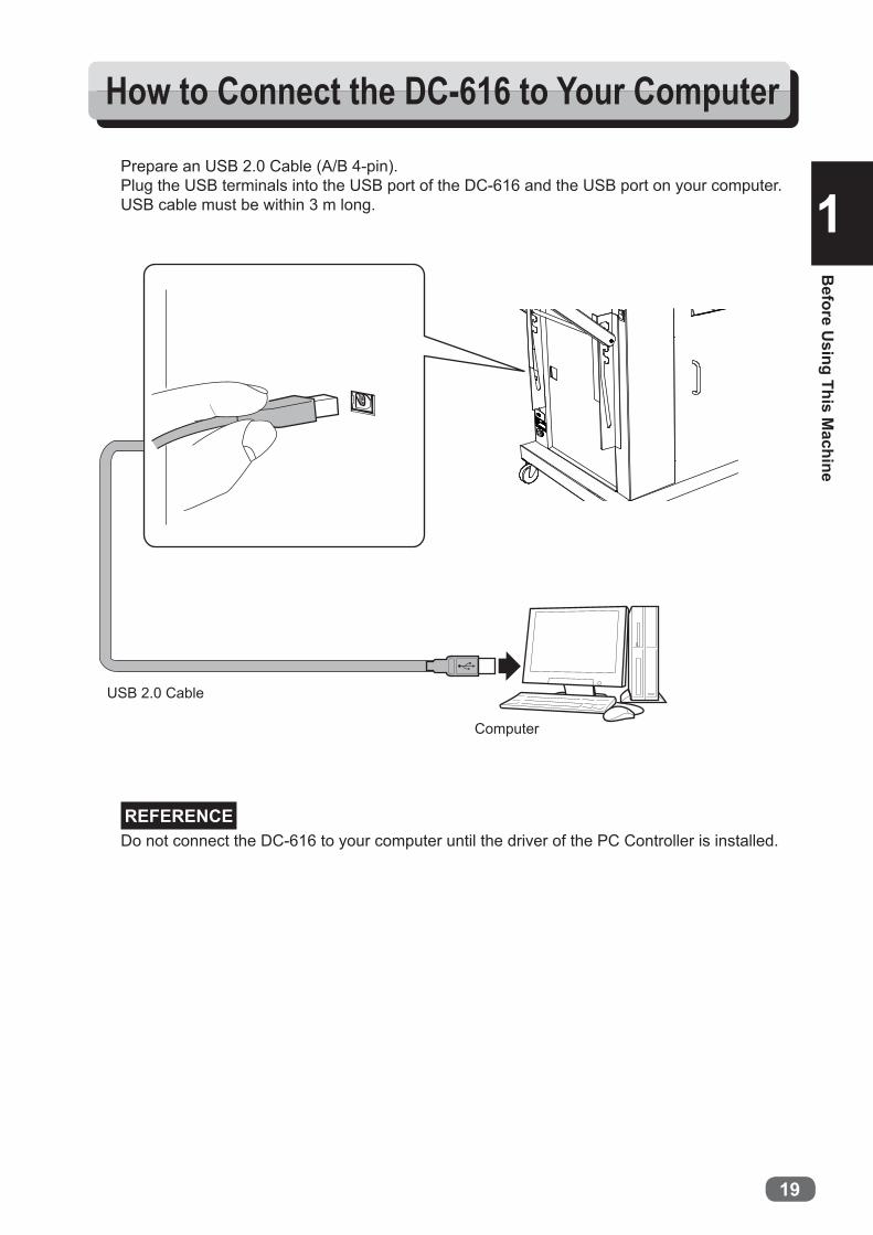
Prepare an USB 2.0 Cable (A/B 4-pin).Plug the USB terminals into the USB port of the DC-616 and the USB port on your computer.USB cable must be within 3 m long.
Do not connect the DC-616 to your computer until the driver of the PC Controller is installed.REFERENCE
Computer
USB 2.0 Cable

20
Before Preparing Document
The DC-616 can save up to 80 patterns of JOB. JOB contents can be programmed either via computer or on the control panel. This chapter describes items required to program a JOB.
Slit : The DC-616 has six slitters. Two slitters (1, 2) are for the margins and the remaining four slitters are for the center area of the document.
Cut : There is a guillotine cutter that performs cuts perpendicular to the document feed direction. The DC-616 can cut up to 25 cuts on one document.
Crease : There is a creaser that performs creases perpendicular to the document feed direction. The DC-616 can crease up to 20 creases on one document.
135
246
1
3
56
4
2
8
9
78910
1
3
56
4
2
No. Name Function
1 Slitter 1 Cuts off the margin of the non-operator’s side.Drops the margin slit by the slitter into the waste box.
2 Slitter 2 Cuts off the margin of the operator’s side.Drops the margin slit by the slitter into the waste box.
3 Slitter 3 Cuts parallel to the document feed direction.4 Slitter 4 Cuts parallel to the document feed direction.5 Slitter 5 Cuts parallel to the document feed direction.6 Slitter 6 Cuts parallel to the document feed direction.
7 Gutter defl ector The gutter strips cut off by slitters are dropped into the waste box.
8 Cutter section Cuts perpendicularly to the document feed direction.9 Creaser section Creases perpendicularly to the document feed direction.
10Perforation unit (Optional on 115V model and 230V Asia model)
Perforates parallel to the document feed direction.
Crease
Cut
Slit 1
Slit 2
Slit 3
Slit 4
Slit 5
Slit 6
Document and processing position

2
21
Before Preparing Document
Before U
sing This Machine
1Defi nition of Programming Terms
Barcode REG mark
Slit 1Slit 2
Slit 3Slit 4
Slit 5Slit 6
REG mark
Barcode
Crease
First cut
Last cut
Document feed direction
Document feed direction

22
Before Preparing Document
Slit : Up to 6 slits are possible on one document.Slit 1 and Slit 2 are for cutting the margins at both side edges.
Cut : Up to 25 cuts are possible on one document. Crease : Up to 20 creases are possible on one document.
Slit / Cut / Crease Limitations
Slit 2 Slit 4 Slit 6 Slit 5 Slit 3 Slit 1
Cut 1
Crease 1
Cut 2
Cut 3
Crease 2
Cut 4
Lead margin:3.0 mm–
Card length:50.0 mm–
Center margin:3.0 mm–(More margin may be required depending on document types.)
Trail margin:5.0 mm–
Right margin:3.2–55.0 mmfrom the right edge
Gutter:5.0–15.0 mm
Card width:48.0 mm 3.2–55.0 mm
from the left edge
Left margin:
Document feed direction

2
23
Before Preparing Document
Before U
sing This Machine
1Document feed direction
Slit 2 Slit 4 Slit 6 Slit 5 Slit 3 Slit 1
2
4.6
3.5 1
Moving range of the slitter
1. Moving range of the slitter 13.2 to 55.0 mm (The width stands at 0 when it is not set.)
2. Moving range of the slitter 2Width of document-(3.2 to 55.0) mm (The width stands at 0 when it is not set.)
3. Moving range of the slitter 348.0 to (Width of document-48) mm (The width stands at 0 when it is not set.)* However, a 48 mm or wider distance is required between input values of the Slitter 3 and
the Slitter 4.4. Moving range of the slitter 4
48.0 to (Width of document-48.0) mm (The width stands at 0 when it is not set.)* However, a 48 mm or wider distance is required between input values of the Slitter 3 and
the Slitter 4.5. Moving range of the slitter 5
48.0 to (Width of document-48.0) mm (The width stands at 0 when it is not set.)* However, a 48 mm or wider distance is required between input values of the Slitter 5 and
the Slitter 6.* However, a 5 mm or more difference is required between input values of the slitter 3 and
slitter 5.6. Moving range of the slitter 6
48.0 to (Width of document-48.0) mm (The width stands at 0 when it is not set.)* However, a 48 mm or wider distance is required between input values of the Slitter 5 and
the Slitter 6.* However, a 5 mm or more difference is required between input values of the slitter 4 and
slitter 6.
* Limitation of the range for each slitter varies by the other slitter’s input values.* The gutter defl ector may not be able to drop the margins when the input value of each slitter
is 55.0–60.0 mm.

24
Before Preparing Document
IMPORTANT
The DC-616 automatically compensates for image drift, one of the common problems on digital printers. It detects the image drift caused on each page by reading REG mark with built-in CCD scanner and adjusts the cut / slit / crease position accordingly.
To use this function, each document must have REG mark printed on them. Please refer to the following instructions for specifi cations and position of REG mark.
1. Specifi cationsREG mark consists of two straight and perpendicular lines.
Line length : 5 mm or more / eachLine thickness : 0.4 mm or more / each
When there are scratches or stains in the printing range of the REG mark, the position may not be corrected.When the read side of the document is rough and glossy, the CCD scanner may not be able to read REG mark and barcode. (The document may diffusely refl ect light.)
2. PositionDocument feed direction : The whole REG mark should be within 3 to 20 mm from the lead edge.Document width direction : The whole REG mark should be within 3 to 20 mm from the right edge.
The illustration below shows the best position to print the REG mark.
REFERENCE
REG Mark (Registration mark) (Optional on 115V model and 230V Asia model)
Document feed direction
Lead mark: correctsfor image drift in thisdirection.
Side mark: correctsfor image drift in this direction.
Use pen tool etc. of your software application to draw two straight and perpendicular lines.
20 mm
3mm3.0 mm
3.0 mm
3mm
20 mm20.0 mm
6 mm
6 mm
20.0 mm5.0 mm or more
5.0 mmor more
0.4 mm or moreREG markposition range
REG mark
1.0 mmor more
2
25
Before Preparing Document
Before U
sing This Machine
1
No check digit
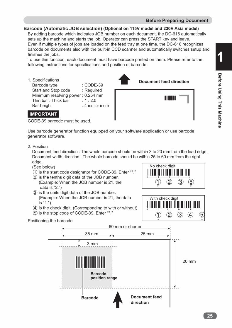
By adding barcode which indicates JOB number on each document, the DC-616 automatically sets up the machine and starts the job. Operator can press the START key and leave. Even if multiple types of jobs are loaded on the feed tray at one time, the DC-616 recognizes barcode on documents also with the built-in CCD scanner and automatically switches setup and fi nishes the jobs.To use this function, each document must have barcode printed on them. Please refer to the following instructions for specifi cations and position of barcode.
1. Specifi cationsBarcode type : CODE-39Start and Stop code : RequiredMinimum resolving power : 0.254 mmThin bar : Thick bar : 1 : 2.5Bar height : 4 mm or more
CODE-39 barcode must be used.
Use barcode generator function equipped on your software application or use barcode generator software.
Positioning the barcode
IMPORTANT
2. PositionDocument feed direction : The whole barcode should be within 3 to 20 mm from the lead edge.Document width direction : The whole barcode should be within 25 to 60 mm from the right edge.(See below)
is the start code designator for CODE-39. Enter “*.”is the tenths digit data of the JOB number.(Example: When the JOB number is 21, the data is “2.”)is the units digit data of the JOB number.(Example: When the JOB number is 21, the data is “1.”)is the check digit. (Corresponding to with or without)is the stop code of CODE-39. Enter “*.”
Document feed direction
Document feed direction
60 mm or shorter
35 mm 25 mm
3 mm
Barcode
Barcodeposition range
20 mm
With check digit
* *
* *
Barcode (Automatic JOB selection) (Optional on 115V model and 230V Asia model)

26
Before Preparing Document
When REG mark and/or barcode are printed outside the specifi ed area, the DC-616 cannot detect them properly. When positioning the REG mark and barcode on the document, take the possibility of image shift into consideration.
The print image other than REG mark and barcode should not be overlapped with the gray-colored area.
3 mmor more
When both of REG mark and barcode are printed on one document
60.0 mm or shorter35.0 mm 5.0 mm 20.0 mm
3.0 mm
REG markBarcode
Non-Printing Area35 mm 5 mm 20 mm
20 mm
REG markBarcodeDocument feed direction
3 mm or more
20 mm
Non-Printing Area
5.0 mm or more
5.0 mmor more
0.4 mm or more
Document feed direction
1.0 mmor more
3.0 mm
1.0 mmor more

2
27
Before Preparing Document
Before U
sing This Machine
1 Limit of Trail Cutting
A
B
Document feed direction
Create a JOB so that fi nished product of less than 67.0 mm is not set up within the trail edge of 67.0 mm.Because the product of less than 67.0 mm cannot be processed as fi nished product, it is fi nely cut.
• Conditions of AA ≥ 67.0 ..... Finished product67.0 > A ≥ 49.0, and A+B=67.0 ..... Finished product67.0 > A ≥ 49.0, and A+B < 67.0 .. WasteA < 49.0 ..... Waste
• Conditions of BB ≥ 67.0 ..... Finished productB < 67.0 ..... Waste

28
Before Preparing Document
Possible JOBPossible JOB
Possible JOBImpossible JOB
49.0 mm and more
49.0 mm and more
49.0 mm and more
67.0 mm 67.0 mm
Document feed direction

Chapter 2
2
Programm
ing JOB
on Control Panel
Programming JOB on Control PanelThis chapter describes how to program a JOB on the control panel of the DC-616.
Before Programming JOB ....................................................................30Programming a JOB on the Control Panel ................................................31Programming a New JOB (Advanced Mode) .............................................33Programming a New JOB (Simple Mode) .................................................39Changing the Stored JOB ....................................................................41

30
Before Programming JOB
The DC-616 can save up to 80 patterns of JOB.This chapter describes how to program and change a JOB on the control panel of the DC-616.
Before programing a JOB, accurately measure the positions of slits, cuts and creases in mm/inch.Familiarize yourself with the following instructions to make the programming process easy and trouble free.
Slitter : There are a total of six slitters. Two sitters are for the margins and the remaining for siltters are the center of a document.
Cutter : There is a guillotine cutter that performs cuts perpendicular to the document feed direction. The DC-616 can cut up to 25 cuts on one document.
Creaser: There is a creaser that performs creases perpendicular to the document feed direction.The DC-616 can crease up to 20 positions on one document.
The DC-616 provides two programming modes, Advanced mode and Simple mode.Select either mode by your preference on the “Slitter entry” screen of “Settings” before programming.
Advanced mode: You can set slit position alternately from side to side in order of unit along the document feed direction. The screen displays “Slit1” to “Slit6”.
Simple mode : You can set slit position in order, from the right side of the document along the document feed direction.The screen displays “Slit A” to “Slit F”.

Programm
ing JOB
on Control Panel
31
2
Programming a JOB on the Control PanelThe following items should be entered to program a JOB.
JOB No.Select a JOB number in which the JOB currently being programmed is saved.
JOB name Enter a JOB name using the NUMERIC keys for easy reference.
Width Enter the width of document.
Length Enter the length of document.
REG mark position (Optional on 115V model and 230V Asia model)When using REG mark reading:Enter the distance between the lead edge of the document and the REG mark, and the distance between the right edge of the document and the REG mark.
Slit position Enter the distances between the right edge of the document and each slit position.The DC-616 can slit up to 6 positions on one document.
Cut position Enter the distances between the lead edge of the document and each cut position. The DC-616 can cut up to 25 positions on one document.
Crease position (Perpendicular to the document feed direction)Enter the distance between the lead edge of the document and each crease position. The DC-616 can crease up to 20 positions on one document.
Slitter guideWhen any slitters are not in use, these slitters act as document guide to stabilize the document conveyance. Recommended for light weight document.
Crease depthThis sets the depth of the crease when creasing a document.Usually set to “MID”.Set to “MAX” for heavy weight document and “MIN” for light weight document.
Auto cutLead margin and trail margin are fi nely cut and dropped in the waste box.When documents do not have lead margin or trail margin, this must be turned off.
Perforating position (Optional on 115V model and 230V Asia model)Enter the distance between the right edge of the document and each perforating position.

Programming a JOB on the Control Panel
32
SpeedSelect the processing speed.Selecting “SLOW” improves fi nishing accuracy.
Air knife (Optional on 230V Asia model)Compressed air is blown out from the front of the document to loosen documents. This prevents double feed.

Programm
ing JOB
on Control Panel
33
2
Programming a New JOB ( Advanced Mode)
Turn on the power.
Make sure the standby screen is displayed on the LCD panel.
Press the F key.
The “Select menu” screen will appear.Select “Enter JOB” using the CURSOR (Up/Down) key and press the SET key.
Hints for entering a JOB:● Pressing the SET key goes on to the next step.● Pressing the CURSOR (Up) key returns to the previous step.● Pressing the CURSOR (Down) key goes on to the next step.● Pressing the STOP key during JOB entering returns to the standby screen.● Pressing the RETURN key returns to the previous screen.
Select a JOB number (01–80) using the NUMERIC keys or the CURSOR (Up/Down) key, and then press the SET key.
Select menu
Retrieve JOBEnter JOBSetting
JOB** entry
01: **************02: **************03: **************

Programming a New JOB (Advanced Mode)
34
Example: Entering “DUPLO” in JOB01
Press the <3> key and the CURSOR (Right) key.
* To delete a character, press the CLEAR key.
Enter a JOB name using the NUMERIC keys.Maximum 13 characters in the table below can be entered.Press the SET key when input is complete.
Press the <8> key twice and the CURSOR (Right) key.
Key Pressing the same key switches character.1 1 ! ” $ % & ’ ( )2 A B C a b c 23 D E F d e f 34 G H I g h i 45 J K L j k l 56 M N O m n o 67 P Q R S p q r s 78 T U V t u v 89 W X Y Z w x y z 90 0C Clear
Space, Moves the cursor to the left.Space, Moves the cursor to the right.
Press the <5> key three times and the CURSOR (Right) key.
Press the <7> key and the CURSOR (Right) key.
DEnter JOB name
DUEnter JOB name
JOB** entry
JOB** entry
DUPLEnter JOB name
DUPEnter JOB name
JOB** entry
JOB** entry

Programming a New JOB (Advanced Mode)
35
Programm
ing JOB
on Control Panel
2
Press the <6> key three times and the CURSOR (Right) key.
Press the SET key or the CURSOR (Down) key.
WidthEnter the width (mm) of the document using the NUMERIC keys. The value must be between 210.0 to 320.0 mm. When input is complete, press the SET key or the CURSOR (Down) key.
Lead mark (Optional on 115V model and 230V Asia model)This screen appears only when CCD is used. When using “REG mark reading” function, enter the distance between the lead edge of the document and the lead mark using the NUMERIC keys. The value must be 3.0 to 15.0 mm.When input is complete, press the SET key or the CURSOR (Down) key.
LengthEnter the length (mm) of the document using the NUMERIC keys. The value must be between 210.0 to 670.0 mm. When input is complete, press the SET key or the CURSOR (Down) key.
Side mark (Optional on 115V model and 230V Asia model)This screen appears only when CCD is used. When using “REG mark reading” function, enter the distance between the right edge of the document and the side mark using the NUMERIC keys. The value must be 3.0 to 15.0 mm.When input is complete, press the SET key or the CURSOR (Down) key.If you enter “0”, the screen skips to step 16.
SlitWhen using “Slit” function, enter the distance from the right edge of the document to the position for “Slit1” using the NUMERIC keys. When input is complete, press the SET key or the CURSOR (Down) key.
REFERENCEInputtable range is displayed in (0/***.*-***.*).
DUPLOEnter JOB name
JOB** entry
Width
(210.0-320.0)***.*mm
JOB** entry
Length
(210.0-670.0)***.*mm
JOB** entry
Side mark
(0/3.0-15.0)**.*mm
JOB** entry
Lead mark**.*mm(3.0-15.0)
JOB** entry
Slit1
(0/***.*-***.*)***.*mm
JOB** entry

Programming a New JOB (Advanced Mode)
36
REFERENCE
Enter the value for “Slit2” to “Slit6” in a similar way to step 16.When each input is complete, press the SET key. When you require fewer than six slits, enter “0” after the last slit setting and then press the SET key or the CURSOR (Down) key.
CutEnter the distance from the lead edge of the document to the position for “Cut1” using the NUMERIC keys. When input is complete, press the SET key or the CURSOR (Down) key.
IMPORTANTWhen you require only one cut, set the “Auto cut” function to “OFF”.
CreaseEnter the distance from the lead edge of the document to the position for “Crease1” using the NUMERIC keys. When input is complete, press the SET key or the CURSOR (Down) key.
IMPORTANT
Slit position setting order:• Advanced mode : Slits are set in numerical order
from “Slit 1” to “Slit 6”. 12 34 56
Document feed direction
Slit6***.*mm(***.*-***.*)
JOB** entry
(0/***.*-***.*)***.*mmCut1
(0/***.*-***.*)***.*mmCut25
(0/***.*-***.*)***.*mmCrease1
JOB** entry
JOB** entry
JOB** entry
There is a limit to trail cutting.(→P.27 “Limit of Trail Cutting”)
Enter the value for “Cut2” to “Cut25” in a similar way to step 18.This value must be “previous cut position +3 mm”.The value for the last cut must be under “the document length -5 mm.When each input is complete, press SET key.When you require fewer than 25 cuts, enter “0” after the last cut setting and then press the SET key or the CURSOR (Down) key.
Programming a New JOB (Advanced Mode)
37
Programm
ing JOB
on Control Panel
2
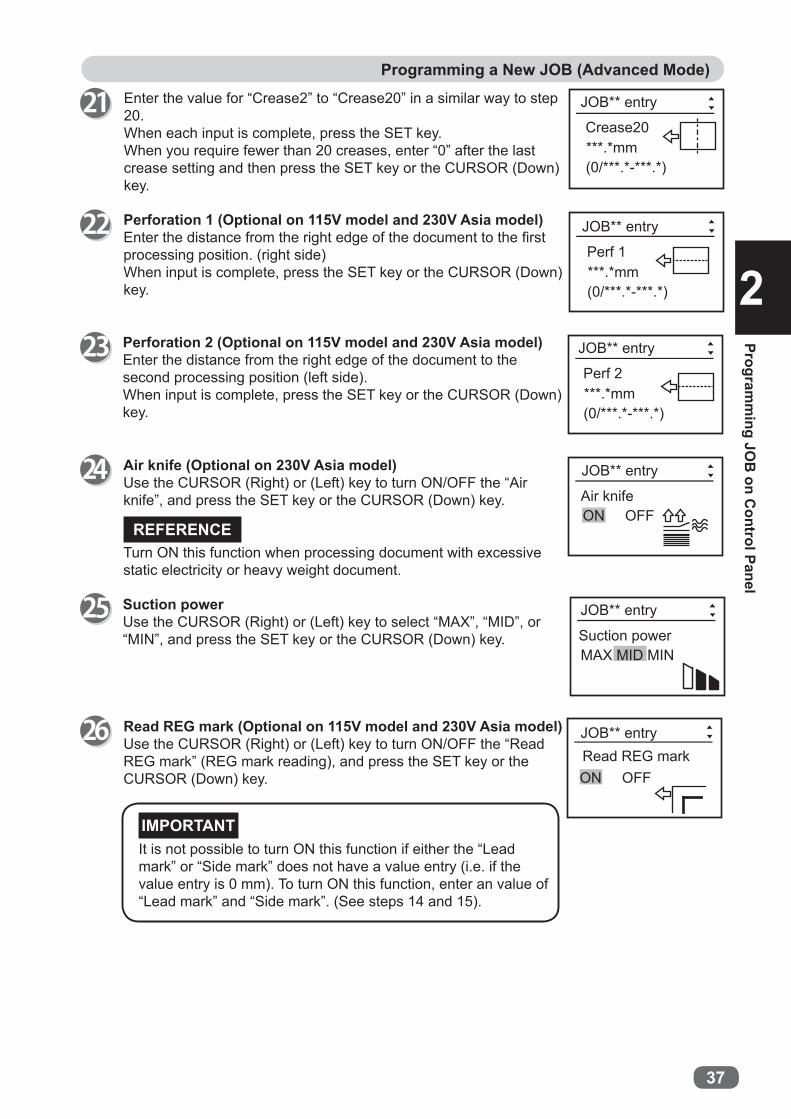
Air knife (Optional on 230V Asia model)Use the CURSOR (Right) or (Left) key to turn ON/OFF the “Air knife”, and press the SET key or the CURSOR (Down) key.
Turn ON this function when processing document with excessive static electricity or heavy weight document.
REFERENCE
Read REG mark (Optional on 115V model and 230V Asia model)Use the CURSOR (Right) or (Left) key to turn ON/OFF the “Read REG mark” (REG mark reading), and press the SET key or the CURSOR (Down) key.
IMPORTANTIt is not possible to turn ON this function if either the “Lead mark” or “Side mark” does not have a value entry (i.e. if the value entry is 0 mm). To turn ON this function, enter an value of “Lead mark” and “Side mark”. (See steps 14 and 15).
Suction powerUse the CURSOR (Right) or (Left) key to select “MAX”, “MID”, or “MIN”, and press the SET key or the CURSOR (Down) key.
(0/***.*-***.*)***.*mmCrease20
Enter the value for “Crease2” to “Crease20” in a similar way to step 20.When each input is complete, press the SET key.When you require fewer than 20 creases, enter “0” after the last crease setting and then press the SET key or the CURSOR (Down) key.
JOB** entry
(0/***.*-***.*)***.*mmPerf 1
JOB** entry
(0/***.*-***.*)***.*mmPerf 2
JOB** entry
Air knifeON OFF
JOB** entry
JOB** entry
Suction powerMAX MID MIN
Read REG markON OFF
JOB** entry
Perforation 1 (Optional on 115V model and 230V Asia model)Enter the distance from the right edge of the document to the fi rst processing position. (right side)When input is complete, press the SET key or the CURSOR (Down) key.
Perforation 2 (Optional on 115V model and 230V Asia model)Enter the distance from the right edge of the document to the second processing position (left side).When input is complete, press the SET key or the CURSOR (Down) key.

Programming a New JOB (Advanced Mode)
38
Crease depthUse the CURSOR (Right) key and (Left) key to select “MAX”, “MID”, or “MIN”, and press the SET key or the CURSOR (Down) key.
SpeedUse the CURSOR (Right) key and (Left) key to select “FAST” or “SLOW”, and press the SET key or the CURSOR (Down) key.
The display shown on the right appears on the screen.To save the JOB, select “YES” and press the SET key.If you want to cancel the settings, press the STOP key.
REFERENCE● When you are selecting already stored JOB number, the
messages “Overwrite JOB**” or “Save as different JOB no.” will appear on the screen.If you select “Overwrite JOB**” and press the SET key, the JOB will be overwritten.
● If you select “Save as different JOB no.” and press the SET key, a list of JOB number will appear on the screen.Use the CURSOR (Up) key or (Down) key to select JOB number, and press the SET key. Every time you press the CURSOR (Right) or (Left) key, the setting details of the highlighted JOB number are displayed.
Slitter guideWhen any slitters are not in use, these slitters act as document guide to stabilize the document conveyance. Use the CURSOR (Right) or (Left) key to turn ON/OFF the “Slitter guide”, and press the SET key or the CURSOR (Down) key.
Slitter guide
ON OFF
JOB** entry
Autol cutON OFF
JOB** entry
Crease depth MAX MID MIN
JOB** entry
FAST SLOWSpeed
YES NO
Enter JOB **?
01: DUPLO02: [No Data]03: [No Data]
Save as different JOB no
Overwrite JOB**
JOB** entry
JOB** entry
JOB** entry
JOB** entry
Auto cutLead margin and trail margin are fi nely cut and dropped in the waste box.Use the CURSOR (Right) or (Left) key to turn ON/OFF the “Auto cut”, and press the SET key or the CURSOR (Down) key.

Programm
ing JOB
on Control Panel
39
2
Programming a New JOB ( Simple Mode)
When programming a JOB in Simple Mode, slitter settings are entered in order as shown on the fi gure below.
Hints for entering a JOB:● Pressing the SET key goes on to the next step.● Pressing the CURSOR (Up) key returns to the previous step.● Pressing the CURSOR (Down) key goes on to the next step.● Pressing the STOP key during JOB entering returns to the standby screen.● Pressing the RETURN key returns to the previous screen.
Simple mode : You can set slit position in order, from the right side of the document along the document feed direction. The screen displays “SlitA” to ”SlitF”.
Proceed with steps 1 to 15 of “Programming a New JOB (Advanced Mode)”.(→P.33 “Programming a New JOB (Advanced Mode)”)
Enter the distance from the right edge of the document to the position for “Slit A” using the NUMERIC keys, and then press the SET key or the CURSOR (Down) key. SlitA
***.*mm(0/***.*-***.*)
JOB** entry
Document feed direction
Slit ASlit BSlit CSlit DSlit ESlit F
F
DE
ABC
Left edge of the document
Right edge of the document
Programming a New JOB (Simple Mode)
40
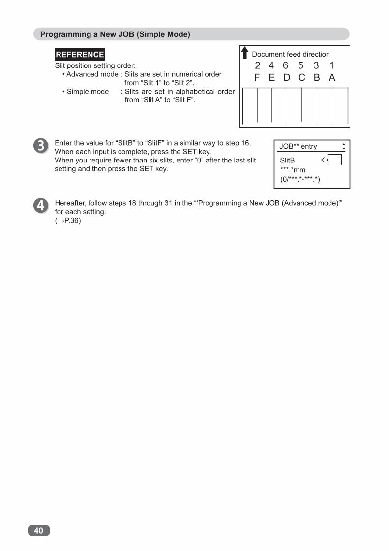
REFERENCESlit position setting order:
• Advanced mode : Slits are set in numerical order from “Slit 1” to “Slit 2”.
• Simple mode : Slits are set in alphabetical order from “Slit A” to “Slit F”.
SlitB***.*mm(0/***.*-***.*)
JOB** entry
12 34 56Document feed direction
ABCDEF
Enter the value for “SlitB” to “SlitF” in a similar way to step 16.When each input is complete, press the SET key.When you require fewer than six slits, enter “0” after the last slit setting and then press the SET key.
Hereafter, follow steps 18 through 31 in the “‘Programming a New JOB (Advanced mode)’” for each setting.(→P.36)

Programm
ing JOB
on Control Panel
41
2
Changing the Stored JOB
This section describes how to change the stored JOB and to overwrite the JOB.
Make sure the standby screen is displayed on the LCD panel.
When input of the last item is completed, the display shown on the right appears.If you save the changes as the currently selected JOB number, press the CURSOR (Up) key or (Down) key to select “Overwrite JOB**”, and then press the SET key.If you save them as different JOB number, press the CURSOR (Up) key or (Down) key to select “Save as different JOB no.”, and then press the SET key.
Press the F key.The “Select menu” screen will appear.
Use the CURSOR (Up) key or (Down) key to select “Enter JOB”, and press the SET key.
The JOB numbers are displayed in ascending order.Use the CURSOR (Up) key or (Down) key to select the “JOB number” that you want to change, and then press the SET key.
Press the SET key or CURSOR (Down) key to select the item to be changed.
Follow the steps in “'Programming a New JOB (Advanced mode)'" for each setting.(→P.33 "Programming a New JOB (Advanced Mode)")
The message “Saving JOB” will appear on the screen and the changed JOB settings are saved in the memory.The display returns to the standby screen shown on the right and the JOB number and the JOB name that were just saved are displayed.
Select menu
Retrieve JOBEnter JOBSettings
01: JOB**02: JOB**03: [No Data]
JOB01entry
Overwrite JOB**Save as different JOB no.
JOB** entry
01: DUPLO


Chapter 3
3
Basic O
perations
Basic OperationsThis chapter describes the operating sequence from turning on the DC-616 until completing process.
Processing Documents by Selecting a JOB ............................................ 44Function Setting ............................................................................. 46Setting Functions ............................................................................ 47Automatic Setup Using Barcodes ........................................................ 52Adjusting Feeder ............................................................................ 54
Elevator level (Feed tray) ............................................................. 54Separator ................................................................................ 54Airfl ow .................................................................................... 54Skew Compensation .................................................................. 55
Adjusting for Using a Light Weight Document ......................................... 56Adjusting the Amount of Airfl ow (Shutter) ......................................... 56
44
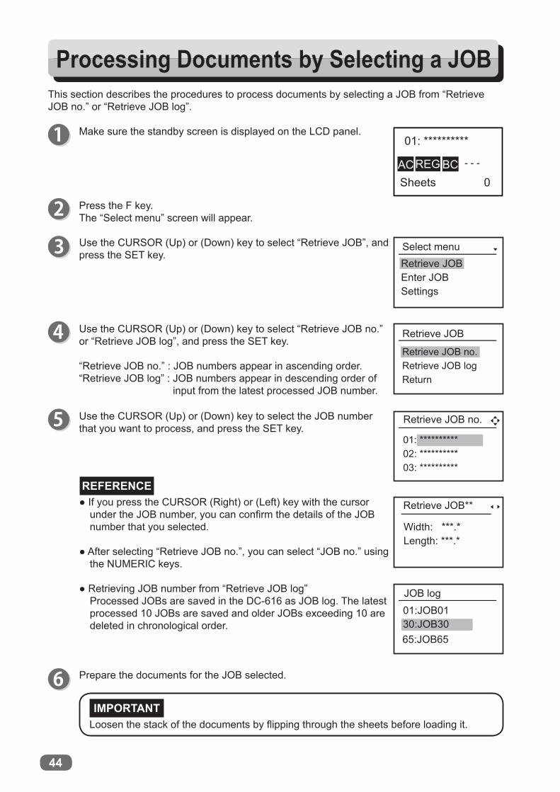
Use the CURSOR (Up) or (Down) key to select the JOB number that you want to process, and press the SET key.
Processing Documents by Selecting a JOB
Make sure the standby screen is displayed on the LCD panel.
This section describes the procedures to process documents by selecting a JOB from “Retrieve JOB no.” or “Retrieve JOB log”.
REFERENCE
Press the F key.The “Select menu” screen will appear.
Use the CURSOR (Up) or (Down) key to select “Retrieve JOB no.” or “Retrieve JOB log”, and press the SET key.
“Retrieve JOB no.” : JOB numbers appear in ascending order.“Retrieve JOB log” : JOB numbers appear in descending order of
input from the latest processed JOB number.
Use the CURSOR (Up) or (Down) key to select “Retrieve JOB”, and press the SET key.
Prepare the documents for the JOB selected.
● If you press the CURSOR (Right) or (Left) key with the cursor under the JOB number, you can confi rm the details of the JOB number that you selected.
● After selecting “Retrieve JOB no.”, you can select “JOB no.” using
the NUMERIC keys.
● Retrieving JOB number from “Retrieve JOB log”Processed JOBs are saved in the DC-616 as JOB log. The latest processed 10 JOBs are saved and older JOBs exceeding 10 are deleted in chronological order.
Loosen the stack of the documents by fl ipping through the sheets before loading it.IMPORTANT
01: **********02: **********03: **********
Select menuRetrieve JOBEnter JOBSettings
Retrieve JOB
Retrieve JOB no.Retrieve JOB logReturn
Retrieve JOB no.
Width: ***.*Length: ***.*
Retrieve JOB**
JOB log01:JOB0130:JOB3065:JOB65

45
2
Processing Documents by Selecting a JOB
Basic O
perations
3
Lift the exit tray.(→P.11 “Setting the Exit Tray”)
Load the documents on the feed tray.(→P.10 “Loading Documents”)
Press the TEST key to process a test run for one sheet. Confi rm whether the fi nished product is processed as it is programmed. If not, make fi ne adjustment in “Function Setting”.
Attach the back guide and the side guides.(→P.11 “Setting the Exit Tray”)
If you already determine the number of document to be processed, use the NUMERIC keys to enter the number of documents.
Adjust the “feed guide” according to the document size and secure it with the “fi xing screw”.Set the “back guide” according to the document.(→P.10 “Loading Documents”)
After the processing is complete, the standby screen appears.
Make sure that the LED on the START key is green, and then press the START key.If it is red, the DC-616 is having an error. Follow the instruction displayed on the LCD panel.

46
Function SettingThe following functions can be set.
Air knife (Optional on 230V Asia model)Compressed air is blown out from the front of the document to loosen the documents, preventing double feed.
Double detection (Double feed detection) (Optional on 115V model and 230V Asia model)This detects double feed (two or more sheets are fed at once).
Read Barcode (Barcode reading) (Optional on 115V model and 230V Asia model)This sets whether to execute automatic setup when reading a barcode.
Read REG mark (Optional on 115V model and 230V Asia model)This sets operation mode when sensing the REG mark. Sensing the REG mark and handling operations at the regular position improve accuracy of documents handling.
Slitter guideWhen any slitters are not in use for performing a JOB, these slitters act as document guide to stabilize the document conveyance.
Crease depthThis sets the depth of the crease when creasing a document.
Apply shrinkageIn case printed document are shrink by heat generated on digital printer, by entering the original document size and document size after shrink, DC-616 automatically calculate the shrinkage ratio and adjust the cutting and creasing position accordingly.This function compensate for the shrinkage in the feed direction only.
Adjust all (JOB vertical position correction)This corrects the document position in vertical direction against the JOB set.This function cannot be set to ON when REG mark or barcode reading setting is ON.
Adjust all (JOB horizontal position correction)This corrects the document position in horizontal direction against the JOB set.This function cannot be set to ON when REG mark or barcode reading setting is ON.
SpeedThis is used to select processing speed.
Slitter entryYou can select “Simple mode” or “Advance mode” for entering a JOB.
Auto cutLead margin and trail margin are fi nely cut and dropped in the waste box.When the document do not have any lead margin or trail margin, this must be turned off.
Suction powerThis adjusts the air amount of the suction fan.When the document is fed, it is suctioned to the conveyance belt and conveyed.

47
3
Basic O
perations
Setting Functions
Turn on the power.
REFERENCE
Make sure the standby screen is displayed on the LCD panel.
Press the F key.The “Select menu” screen will appear.
Use the CURSOR (Up) or (Down) key to select “Settings”, and press the SET key.
Select menu
Retrieve JOBEnter JOBSettings
Select menu
Retrieve JOBEnter JOBSettings
Settings
Air knifeON OFF
The temporarily set functions by Function Setting are valid until the power is turned OFF or another JOB is selected. The already stored JOB details are not overwritten.“DBL detection” and “Feeder capacity” are valid even after turning off the power.
*/**
*/**
MAX MID MIN
Settings
Suction power
Air knife (Optional on 230V Asia model)Compressed air is blown out from the front of the document to loosen the documents, preventing double feed. Use the CURSOR (Right) or (Left) key to select “ON” or “OFF”, and press the CURSOR (Down) key.When using light weight document, select “OFF”.
Suction powerWhen the document is fed, it is suctioned to the conveyance belt and conveyed.Use the CURSOR (Right) or (Left) key to select “MAX”, “MID”, or “MIN”, and press the CURSOR (Down) key.

48
Setting Functions
Double detection (Optional on 115V model and 230V Asia model)This detects double feed (two or more sheets are fed at once).Use the CURSOR (Right) or (Left) key to select “ON” or “OFF”, and press the CURSOR (Down) key.
IMPORTANTDouble feed may not be detected if you are using rough-textured document.
Read Barcode (Optional on 115V model and 230V Asia model)This sets whether to perform automatic setup when reading the barcode.Use the CURSOR (Right) or (Left) key to select “ON” or “OFF”, and press the SET key.
REFERENCE
*/**Settings
Read REG mark
Slitter guideON OFF
Settings */**
Double detectionON OFF
Settings */**
Read BarcodeSettings
ON OFF
*/**
FAST NORMAL OFF
Auto cut
Settings */**
ON OFF
Read REG mark (Optional on 115V model and 230V Asia model)This sets REG mark reading function.Using the CURSOR (Right) or (Left) key to select “FAST”, “NORMAL”, or “OFF”, and press the CURSOR (Down) key.When not using this function, select “OFF”.
When the lead mark or side mark is “0 mm”, this function is set to “OFF” forcibly.
Slitter guideWhen any slitters are not in use for performing a JOB, these slitters act as document guide to stabilize the document conveyance.Use the CURSOR (Right) or (Left) key to select “ON” or “OFF”, and press the CURSOR (Down) key.
Auto cutLead margin and trail margin are fi nely cut and dropped in the waste box.Use the CURSOR (Right) or (Left) key to select “ON” or “OFF”, and press the CURSOR (Down) key.

49
2
Setting Functions
Basic O
perations
3
Crease depthUse the CURSOR (Right) or (Left) key to select “MAX”, “MID”, or “MIN”, and press the CURSOR (Down) key.
• Set to “MAX” for heavy weight document and “MIN” for light weight document.
• The above screen appears only when value is entered to “Crease”.
REFERENCE
Apply shrinkageIn case printed documents are shrunk by heat generated on digital printer, by entering the original document size and document size after shrunk, the DC-616 automatically calculates the shrinkage ratio and adjusts the cutting and creasing position accordingly.Use the NUMERIC keys to enter the original document length (Before), then enter the shrunk document length (After).
REFERENCE
Crease depthSettings
MAX MID MIN
*/**
Apply shrinkageBefore → After***.*mm→***.*mm
Settings */**
Settings */**
Settings */**
Adjust all ↔+ ***.* mm- ***.* mm
Adjust all ↕+ ***.* mm- ***.* mm
Adjust all (in vertical direction)This function corrects the document position in vertical direction against the JOB set (mm).Use the CURSOR (Up) or (Down) key to select moving direction (+/−), then use the NUMERIC keys to enter the value.Press the CURSOR (Down) key.
Adjust all (in horizontal direction)This function corrects the document position in horizontal direction against the JOB set (mm).Use the CURSOR (Up) or (Down) key to select moving direction (+/−), then use the NUMERIC keys to enter the value.
REFERENCE
REFERENCE
When you press and hold the CLEAR key, the value of “Before” and “After” will be changed to the one that was saved.
“Read REG mark” correction and “Adjust All ” cannot be set at the same time.
“Read REG mark” correction and “Adjust All ” cannot be set at the same time.

50
Setting Functions
SpeedUse the CURSOR (Right) or (Left) key to select “FAST” or “SLOW”, and press the CURSOR (Down) key.
Simple mode : You can set slit position in order, from the right side of the document along the document feed direction.
Advanced mode: You can set slit position alternately from side to side in order of module along the document feed direction.
IMPORTANT● If you exit Function Setting without pressing the SET key, the function set are not
saved.● If you press the SET key before completing Function Setting, the setting you just input
is saved and the standby screen appears.
IMPORTANT
SpeedFAST SLOW
Settings */**
Slitter entrySimple mode
Settings */**
Save shrinkage &Adj. All in JOB**for future?YES NO
Save shrinkagein JOB**for future?YES NO
Save Adjust Allin JOB**for future?YES NO
Slitter entryUse the CURSOR (Right) key or (Left) key to select “Simple mode” or “Advanced mode”.
Press the SET key.If you press the CURSOR (Down) key, the screen returns to “Air knife” in step 5.
● The message on the right appears on the screen when you re-enter the value of “Apply shrinkage” in step 13, “Adjust all (in vertical direction)” in step 14, and “Adjust all (in horizontal direction)” in step15.
● The message on the right appears on the screen when you re-enter the value of “Apply shrinkage” in step 13.
● The message on the right appears on the screen when you re-enter the value of “Adjust all (in vertical direction)” in step 14 or “Adjust all (in horizontal direction)” in step15.
If you select “YES” and press the SET key, the function setting will be saved both in “Settings” and in the JOB.If you select “NO” and press the SET key, the function setting will be saved in “Settings” only.

51
2
Setting Functions
Basic O
perations
3
REFERENCE
The stand by screen appears.
REFERENCE
Trail cut lengthbecomes invalid.All adjust andshrinkage is
cleared.
1 2
1: “%” appears when you set “Apply shrinkage” in “Settings”.2: “ ” appears when you set “Adjust all” in “Settings”.
If the message on the right appears on the screen, the result from the caluculation of the values of “Adjust all” (for both directions) and “Apply shrinkage” is that the cut position is out of the specifi cations.Re-enter value for the cut position, or “Adjust all” or “Apply shrinkage”.

52
Automatic Setup Using BarcodesBy adding barcode which indicates job number on each document, the DC-616 automatically sets up the machine and starts JOB.
Prepare the document suiting the JOB selected, then loosen the stack of the document by fl ipping through the sheets.
Turn on the power.
Set the document in the feed tray as the barcode and REG mark printing side facing upward.
REFERENCEThe height of the document stack should not exceed the MAX level.
Attach the back guide.
Lift the exit tray as shown in the right fi gure.
REFERENCE● When the fi nished document size is A3 (11”×17”)
or longer, it is recommended to set the exit tray in the downward position.
● If the fi nished products are adhered on the exit tray due to static electricity, set the exit tray in the downward position.

53
2
Automatic Setup Using Barcodes
Basic O
perations
3
By pressing the START key, the built-in CCD reads the barcoded JOB number, then starts processing the suitable JOB.
IMPORTANTMake sure that “BC” appears on the standby screen after setting.
The fi nished products are ejected.
IMPORTANTSlit waste accumulates in the waste box.Open the front cover and remove them periodically.Accumulation of waste may cause paper jam.
Read BarcodeSettings
ON OFF
*/**
Attach the back guide and the side guides.
Set “Read Barcode” to “ON” in “Settings”.

54
The elevator level should be adjusted in the following cases:
a. The machine does not feed.
Elevator level (Feed tray)
Level adjustment knob
Separator adjustment knob
Airfl ow adjustment knob
Adjusting Feeder
Separator
Airfl owThe amount of airfl ow should be adjusted in the following cases:
a. The machine does not feed.
The height of the separator should be adjusted in the following cases:
a. The machine does not feed.
→ Turn the level adjustment knob in a counterclockwise direction (to a smaller number).The level of the elevator is raised.
→ Turn the level adjustment knob in a clockwise direction (to a larger number).The level of the elevator is lowered.
b. The machine feeds multiple sheets at once.(double feed)
→ Turn the separator adjustment knob in a counterclockwise direction (to a smaller number). The position of the separator is raised.
b. The machine feeds multiple sheets at once.(double feed)
→ Turn the separator adjustment knob in a clockwise direction (to a larger number).The position of the separator is lowered.
→ Turn the airfl ow adjustment knob in a counterclockwise direction (to a smaller number).The amount of airfl ow is decreased.
→ Turn the airfl ow adjustment knob in a clockwise direction (to a larger number).The amount of airfl ow is increased.
b. The machine feeds multiple sheets at once.(double feed)
For light weight document For heavy
weight document
For light weight document
For heavy weight document
For light weight document
For heavy weight document

55
2
Adjusting Feeder
Basic O
perations
3
If the fi nished products are cut obliquely, adjust the skew using the skew adjustment knob.
Skew Compensation
Press the TEST key to perform a test run for one sheet and check the fi nished products.
Clockwise : Turning the knob slightly shifts the lead edge of the document toward the operator's side.
Counterclockwise : Turning the knob slightly shifts the lead edge of the document toward the non-operators side.
If the skew remains, repeat the above steps 1 and 2 again.

56
Adjusting for Using a Light Weight Document
Adjusting the Amount of Airfl ow (Shutter)When you use the light weight document, the double feed may occur even if you adjust the “airfl ow adjustment knob”.In that case, adjust the amount of airfl ow by opening and closing the “shutter” on the document feed side.
Slide the “shutter knob” to the right to close the “air outlet”.
Document feed side
Suction unit
Open CloseShutter

Chapter 4
4
Troubleshooting
TroubleshootingThis chapter describes what to do when an error has occurred and how to deal with paper jams and error messages.
When Messages Appear ......................................................................58When a Paper Jam Has Occurred ..........................................................63
Example: J3 Feed error ..................................................................63Example: J7 WASTE BOX ..............................................................64

58
Message Status and SolutionStatus : There is no document on the feed tray.Solution : Load document on the feed tray.(→P.11 “Loading Documents”)
Status : The top cover is open.Solution : Close the top cover.
Status : The front cover is open.Solution : Close the front cover.
Status : The perforation unit or the cover is not installed.Solution : Install the perforation unit or the cover.
Status : Double feedSolution : Remove the document from the inside of the machine and
then press the STOP key.
Status : Too many documents are loaded on the feed tray.Solution : The height of the document stack should not exceed the
MAX level. (There is an indication on the right side of the feed tray.) Remove the documents and then press the STOP key.
Status : There is paper jam in the document infeed area or feeding area.
Solution : Remove the document from the infeed area or feeding area and then press the STOP key.
(→P.63 “Example: J3 Feed error”)
Status : There is paper jam in the slitter area.Solution : Remove the document from the slitter area and then press
the STOP key.
When input value of each slitter is 55-60, the gutter defl ector may not be available.
When Messages AppearWhen an error occurs, messages and fi gure appear on the LCD panel. In such cases, follow the procedures below to solve the cause.
IMPORTANT
Place documenton feed tray
to Clear
Feed trayoverload
to Clear
Remove documentfrom feed area
to Clear
No document
J2 Feed tray
Cover open
Close cover
J3 Feed error
TOP/FRONT/EXIT
J4 Slitter
Remove documentfrom slitter area
to Clear
Remove documentin the machine
to Clear
Double feed

2
59
When Messages Appear
4
Troubleshooting
Message Status and SolutionStatus : There is paper jam in the cut or crease area.Solution : Remove the document from the cut or crease area and then
press the STOP key.
Status : There is paper jam in the paper exit area.Solution : Remove the jammed documents from the exit area and then
press the STOP key.
Status : The waste box became full during processing.Solution : Remove the accumulated waste from the waste box and
then press the STOP key.(→P.64 “Example: J7 WASTE BOX”)
Status : The slitter is locked.Solution : Remove the document from the sillter area and then press
the STOP key.Turn off the power and then turn on again after a few seconds. If the same message appears, contact our service person.
Status : The cutter is locked.Solution : Remove the document from the cutter area and then press
the STOP key.Turn off the power and then turn on again after a few seconds. If the same message appears, contact our service person.
Status : The creaser is locked.Solution : Remove the document from the creaser area and then press
the STOP key.Turn off the power and then turn on again after a few seconds. If the same message appears, and contact our service person.
Status : Check paper jam in the slitter area.Solution : Remove the document from the slitter area and then press
the STOP key.
Status : Check paper jam in the cut or crease area when the power is turned on.
Solution : Remove the document from the cut or crease area and then press the STOP key.
J5 Cut, crease
Remove documentfrom cut/creasearea to Clear
J6 Exit tray
Remove documentsfrom exit tray
to Clear
J7 Waste box
Remove documentfrom waste box
to Clear
Check documentin slitter area
to Clear
Slitter* lock
Check documentin cutter area
to Clear
Cutter lock
Check documentin creaser area
to Clear
Creaser lock
Remove documentfrom slitter area
Paper in machine
Remove documentfrom cut/creasearea
Paper in machine

60
When Messages AppearWhen Messages Appear
Message Status and SolutionStatus : Check paper jam in the exit area when the power is turned
on.Solution : Remove the document from the exit area and then press the
STOP key.
Status : Check waste jam in the waste box.Solution : Remove the waste from the waste box and then press the
STOP key.
Status : The machine failed to read barcode.Solution : Press the STOP key and check that the barcode is printed
clearly at the correct position.If it is not printed within the specified area, print it on appropriate position.
Turn off the power and then turn on again after a few seconds.If the same message appears, contact our service person.
Status : JOB** is not stored.“**” shows JOB number.
Solution : Press the STOP key and then check JOB contents.(→P.25 for barcode specifi cations)
Status : Check digit error or barcode error.Solution : Press the STOP key to clear the error and then check
barcode. (Is digit correct?, Are any alphabets included?)Make a document with correct barcode.
Status : The machine failed to read REG mark.Solution : Press the STOP key and check that there is no blot on the
document.(→P.24 for REG mark specifi cations)
Status : The machine failed to read REG mark.Solution : Press the STOP key and check whether the REG mark is
correctly printed.(→P.24 for REG mark specifi cations)
Paper in machine
Remove documentfrom waste box
BC read error 1
BC read error 2
BC read error 3
JOB ** is unknown
to clear
Check digiterror
to Clear
REG read error 1
Check documentis not marked
to Clear
Remove documentfrom exit trayarea
Paper in machine
Cannot readbarcode
to Clear
REG read error 2
Cannot readREG mark
to Clear

2
61
When Messages Appear
4
Troubleshooting
Message Status and SolutionStatus : The machine failed to read REG mark.Solution : Press the STOP key, then check whether the REG mark is
printed straight and the document is not skewed.
Status : The machine failed to read REG mark.Solution : Press the STOP key, then check REG mark position and
margin slitter position. If REG mark is not printed within the specifi ed area, print it on appropriate position
.
Status : Barcode error and REG mark error.Solution : ●Press the STOP key and check the JOB.
●Press the STOP key and check that barcode and REG mark are printed.●Press the STOP key and check the position of barcode and REG mark. If they are not printed within the specified area, print them on appropriate positions.
Turn off the power and then turn on again after a few seconds.If the same message appears, contact our service person.
Status : JOB requiring the gutter deflector is selected.Solution : Set the gutter deflector.
Status : JOB that does not use the gutter deflector is selected.Solution : Clear the gutter deflector.
Status : The machine judges that the document cannot be fed because the JOB was changed after reading barcode.
Solution : Set the option that is appropriate for the JOB and press the STOP key.
Status : Check the perforation tool positions.Solution : Check whether the tool positions are correct and press the
STOP key.
Set correctoption
to clear
WRONG OPTION
REG read error 3
Cannot readREG mark
to Clear
REG read error 4
Check REGposition
to Clear
SetGutter defl ector
to Clear
Gutter defl ector
ClearGutter defl ector
to Clear
Gutter defl ector
Check positionsof option tools.
to Clear
CCD read error ▼
Cannot readbarcode
to Clear
CCD read error ▲
Cannot readREG mark
to Clear

62
When Messages AppearWhen Messages Appear
Message Status and SolutionStatus : The machine cannot perform JOB because of the false data
received from personal computer.Solution : Check the JOB details and then press the STOP key.
Status : When the perforation unit is installed or you select the JOB that uses the perforation unit, you press the START key or the TEST key.
Solution : Check if the option unit is correctly installed and then press the STOP key or the TEST key to restart processing.
Status : When “Apply shrinkage” is set to ON, the trail crease position is out of specifi cation.
Solution : Set “Apply shrinkage” to OFF or change the trail crease position.
Status : When “Apply shrinkage” is set to ON, the lead crease position is out of specifi cation.
Solution : Set “Apply shrinkage” to OFF or change the lead crease position.
Status : When “Apply shrinkage” is set to ON, the trail cut position is out of specifi cation.
Solution : Set “Apply shrinkage” to OFF or change the trail cut position.
Status : When “Apply shrinkage” is set to ON, the lead cut position is out of specifi cation.
Solution : Set “Apply shrinkage” to OFF or change the lead cut position.
Status : Error occurred in the DC-616.Solution : Turn off the power and then turn on again after a few
seconds.
If the same message appears, contact our service person.
JOB error
Check JOB detail
to Clear
E** - - - error
Check positionof options
to start
Trail crease length becomes invalid.All adjust and shrinkage iscleared.
Lead crease lengthbecomes invalid.All adjust andshrinkage iscleared.
Trail cut lengthbecomes invalid.All adjust and shrinkage iscleared.
Lead cut length becomes invalid.All adjust and shrinkage iscleared.

63
4
Troubleshooting
When a paper jam has occurred, a message appears on the LCD panel.Follow the procedures below to remove the jammed document.
When a Paper Jam Has Occurred
WARNING• Do not touch the tool. Doing so may cause injury.• Before removing the jammed document make sure that the machine is fully stopped. Use
the pliers that came with the machine to prevent your hands or fi ngers from being caught.
Press the JOG (Forward) key to eject the document.
Example: J3 Feed error
IMPORTANT
A paper jam has occurred in the document infeed area or feeding area.Follow the procedures below to remove the jammed document.
• Be sure to close the top cover when you operate the machine. The machine does not work if the top cover is open.
• The JOG (Backward) key is inactive when a document is jammed or remains in the feed area.
Press the STOP key to clear the error.The machine will be reset and the error message will be cleared.
J3 Feed error
Remove documentfrom feed area
to clear

64
When a Paper Jam Has OccurredWhen a Paper Jam Has Occurred
● If the jammed document cannot be removed by the procedures on the previous page, attempt to remove the document according to the following procedures.
Open the top cover and remove the jammed document using the pliers that come with the machine.
The waste box becomes full of waste during operation. Accumulation of waste may cause paper jam.
Example: J7 WASTE BOX
Open the front cover, then take out the waste box.Dispose of the waste.
If waste remains inside the machine, remove them.
Put the waste box back in its place and close the front cover.
IMPORTANT• Make sure to set the waste box properly pushing it all the way in.
Press the STOP key to clear the error.The machine will be reset and the error message will be cleared.
● Make sure that the machine is fully stopped before removing the waste.Or your hands or fi ngers may get caught and injured.
WARNING
Remove documentfrom waste box to clear
J7-*

Chapter 5
Daily M
aintenance
5
Daily MaintenanceThis chapter describes daily maintenance for the machine.
Daily Maintenance .............................................................................66Cleaning the Slitter Tool .................................................................66Cleaning the Conveyance Rollers .....................................................67Cleaning the Skew Correction Belt ....................................................68
Waste box .......................................................................................69

66
Clean the machine periodically to maintain its performance.
● Before cleaning, be sure to turn the power off, wait until the machine cools off and unplug the power cord. Otherwise, fi re or electric shock may occur.
● Never remove covers on the machine or modify them.● Do not spill water or any liquid inside of the machine. It may cause fi re or electric
shock. If it happens, contact our service person.
Clean the exterior in the following procedures.1. Tightly wring a soft cloth that has been moistened with water or mild detergent.2. Wipe the exterior.3. Wipe off the excess moisture on the exterior with a dry soft cloth.
● Never use alcohol or solvent cleaner. It may tarnish or damage the exterior fi nish.● Do not put diluted petroleum or insecticide. It may cause fi re.
Daily Maintenance
Cleaning the Slitter ToolIf a document is slit by the slitter after a long period of use of the machine, fi nished products may get dirty.Before starting operation, clean the slitter tool with an air blower, then perform test run several times and check the fi nished products for any blot.
Dust accumulation may cause the machine to malfunction. Clean it periodically.Contact our service person as for cleaning of inside of the machine.
WARNING
WARNING
WARNING
Air blower
Slitter
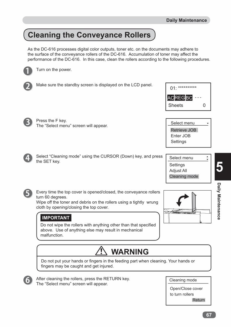
2
67
Daily Maintenance
Daily M
aintenance
5
As the DC-616 processes digital color outputs, toner etc. on the documents may adhere to the surface of the conveyance rollers of the DC-616. Accumulation of toner may affect the performance of the DC-616. In this case, clean the rollers according to the following procedures.
Turn on the power.
Do not wipe the rollers with anything other than that specifi ed above. Use of anything else may result in mechanical malfunction.
After cleaning the rollers, press the RETURN key.The “Select menu” screen will appear.
IMPORTANT
Cleaning the Conveyance Rollers
Do not put your hands or fi ngers in the feeding part when cleaning. Your hands or fi ngers may be caught and get injured.
Every time the top cover is opened/closed, the conveyance rollers turn 60 degrees.Wipe off the toner and debris on the rollers using a tightly wrung cloth by opening/closing the top cover.
Make sure the standby screen is displayed on the LCD panel.
Press the F key.The “Select menu” screen will appear.
Select “Cleaning mode” using the CURSOR (Down) key, and press the SET key.
WARNING
Retrieve JOBEnter JOBSettings
Select menu
Select menuSettingsAdjust AllCleaning mode
Open/Close coverto turn rollers
Return
Cleaning mode

68
Daily MaintenanceDaily Maintenance
Open the top cover.
Close the top cover.
Cleaning the Skew Correction BeltLong hours of machine use result in accumulation of paper dust.Wipe off the paper dust with a cloth while turning the skew correction belt with your hand.
Wipe off the paper dust with a cloth while turning the skew correction belt with your hand.
Do not put your hands or fi ngers in the feeding part when cleaning. Your hands or fi ngers may be caught and get injured.
Do not wipe the skew correction belt with anything other than that specifi ed above. Use of anything else may result in mechanical malfunction.
IMPORTANT
WARNING

69
Daily M
aintenance
5
Waste Box
Slit waste accumulates in the waste box. Open the front cover and remove them periodically. Accumulation of waste may cause paper jam.Follow the instructions below for removing the waste.
Confi rm that the machine is fully stopped.
Be sure to confi rm that the machine is fully stopped before removing the accumulated waste to prevent your hands or fi ngers from being caught.
Put the waste box back in its place and close the front cover.
If waste remains inside the machine when taking out the waste box, remove them.
Open the front cover and take out the waste box. Then remove the waste in the waste box.
WARNING


Specifi cations
7
Specifi cations
Chapter 6
Specifi cations
6
Specifi cationsThis chapter lists the machine specifi cations.
Specifi cations ................................................................................. 72

72
Specifications
Model name DC-616Product type Slitter/Cutter/Creaser Floor stand modelFeeding method Belt suctionInfeed document size Width: 210–320 mm
Length: 210–670 mm** The standard feed tray takes up to 460 mm. For longer sheet, the
optional long paper tray is available.Minimum fi nishing size Width: 48 mm (1.89 in)
Length: 50 mm (1.97 in)*The distance between the lead edge of the last card and the trail edge of the parent sheet should be 67 mm or more.
Document type Uncoated, coated, laminated** Laminated document is not included in the specifi cations of the
perforation unit.)Document weight 110 gsm–350 gsm
Paper curl Within 5 mm Feeder capacity 100 mm Speed 10 ppm (A4 SEF, 2 cuts, 1 crease)Number of slits Max 6 slits per document (2 margin slitters and 4 center slitters)Margin slit spec 3.2–55.0 mm from document side edgesGutter slit width 5.0–15.0 mm
Gutter slits wider than above are exited onto the exit tray.Gutter defl ector Max 2 gutter slits can be defl ected.Number of cuts Max 25 per documentCut position spec Lead edge: min. 3.0 mm
Gutter cut: min. 3.0 mmTrail edge: min. 5.0 mm
Number of creases Max 20 per documentCrease depth adjustment 3 steps (from control panel)Tolerance +/-0.3 mm from programmed positions
(+/-0.4 mm with business cards)When creasing, it may fl uctuate depending on the number of creases and their depths.
Stacker capacity 100 mm (with card stacker: 40 mm)Control panel 64×128 dots LCDLCD languages Japanese, English, French, German, Italian, Spanish, Polish, RussianSoftware update DDL-01, DDL-02Perforation unit Operator replaceable unit
Max 2 perforations parallel to the feeding directionManual positioning
Perforation position Minimum distance from the card side edge: 5 mmMinimum distance between 2 perforations: 48 mm
Perforation tool spec Cut: 0.84 mm Tie: 0.84 mm

2
Specifi cations
73
Specifi cations
6
Model name DC-616Functions 80 job memory
Test feed Skew adjustmentSlitter guideAuto cutApply shrinkageAdjust allCleaning modeAutomatic job setup by reading barcode (CCD is optional on “115V” and “230V Asia Oceania” models.)Image shift compensation by reading REG mark (CCD is optional on “115V” and “230V Asia Oceania” models.)
Options Air knife (optional on “230V Asia Oceania” model)Double feed detection (optional on “115V” and “230V Asia Oceania” models)CCD (standard on “115V PRO” and “230V EMEA” models)Card stacker (optional on “230V Asia Oceania” model)Perforation unit (optional on “115V” and “230V Asia Oceania” models)Long paper trayPC am mount (standard on “115V PRO” model)PC controller software (standard on “115V PRO” model)
USB (B TYPE CONNECTOR)Compatible OS:
Windows XP Professional/Home edition (x86 32bit only)Windows Vista Ultimate/Business/Home basic/Home premiumWindows 7 Ultimate/Professional/Home premiumWindows 8 Professional/Enterprise
Power supply 115 VAC, 60 Hz230 VAC, 50/60 Hz
Power consumption 115 V: current consumption 1.5 A (standby: 0.25 A) power consumption 190 W (standby: 26 W)
230 V: current consumption 0.7 A (standby: 0.22 A) power consumption 190 W (standby: 26 W)
Dimensions In use: 1610 (W) × 625 (D) × 1060 (H) mmIn use with max paper: 2025 (W) × 625 (D) × 1060 (H) mmStored: 975 (W) × 625 (D) × 1060 (H) mmPacked: 1140 (W) × 770 (D) × 1360 (H) mm
Machine weight 115 V: 145 kg (Gross weight: 178 kg)115 V PRO: 155 kg (Gross weight: 188 kg)230 V EMEA: 150 kg (Gross weight: 183 kg)230 V Asia Oceania: 140 kg (Gross weight: 173 kg)
Operating temperature 10–30 degrees (Celsius) (50-80 degrees (F))Operating humidity 40%–70% RH (No condensation)Storing temperature 5–35 degrees (Celsius)Storing humidity 20%–70% RH (No condensation, No exposure to salt)Operating altitude Max 1000 m ALTSafety standard UL, CE, VCCI
● The specifi cations are subject to change without prior notice.

Specifi cations
74
Document CurlDue to the automated slitter function design, the document path of the DC-616 is sensitive to document curl.If document curl is causing document jams, the following are suggestions for remedying the problem:
1. Adjust the printing devices de-curler (if available).2. Manually de-curl the stock before loading in the feed tray.3. Turn the document over (reprogramming the job may be necessary).4. Use different document stock.

75
Appendix
AppendixThis chapter lists an index.
Index ............................................................................................ 76

76
Index
A
AC ..............................................................7AC inlet ........................................................4Adjust all ..............................................46,49Adjusting Feeder ......................................54Adjusting for Using a Light Weight
Document .........................................56Adjusting the Card Stacker Guides ........17Advanced mode ...................................30,33Airfl ow .......................................................54Airfl ow adjustment knob ............................3Air knife ......................................32,37,46,47Apply shrinkage ...................................46,49Attaching the Card Stacker .....................16Auto cut ......................................31,38,46,48Automatic Setup Using Barcodes ...........52
B
Back guide ..................................................4Barcode .....................................................25BC ..............................................................7
C
CCD .........................................................5,35Changing the Perforation Tool Depth .....15Changing the Perforation Tool Position .14Cleaning mode ............................................7Cleaning the Conveyance Rollers ...........67Cleaning the Skew Correction Belt .........68Cleaning the Slitter Tool ..........................66CLEAR key ..................................................6Control panel ..............................................2Crease ..............................................20,22,36Crease depth ..............................31,38,46,49Crease position .........................................31Creaser ......................................................30Creaser module ..........................................5CURSOR (Left/Right) key ...........................6CURSOR (Up/Down) key ............................6Cut ..................................................20,22,36
Cut position ...............................................31Cutter .........................................................30Cutter module .............................................5
D
Daily Maintenance ....................................66Double detection .................................46,48Double feed detection ................................5
E
Elevator level (Feed tray) .........................54Enter JOB ....................................................7Exit tray .......................................................2
F
Feed tray ......................................................2F key ............................................................6
G
Gutter defl ector ...........................................5
I
Installing the Perforation Unit ................. 11Interlock System for Safety .......................x
J
JOB name ...............................................7,31JOB No. ..................................................7,31JOG (Forwad/Backward) key .....................6
L
LCD panel ....................................................6Length ...................................................31,35Level adjustment knob ...............................3Limit of Trail Cutting .................................27Loading Documents .................................10Locations of Warning Labels .................viii
M
Machine Dimensions and Required Space for Operation .....................................xi

77
Appendix
IndexIndex
N
Notes on Safety (Please Read and Observe) ............................................iv
NUMERIC key ..............................................6
P
Perforating position .................................31Perforation ................................................37Perforation unit ...........................................4Power switch ...............................................4
R
Read Barcode ......................................46,48Read REG mark ..............................37,46,48REG ..............................................................7REG Mark ..................................................24REG mark position ...................................31Removing the Perforation Unit ................13Retrieve JOB ...............................................7Return ..........................................................7RETURN key ................................................6
S
Scale ............................................................2Separator ...................................................54Separator adjustment knob .......................3SET key ........................................................6Settings .......................................................7Setting the Exit Tray ................................. 11Side guide ...................................................4Simple mode ........................................30,39Skew adjustment knob ...............................3Skew Compensation ................................55Slit 20,22Slit position ...............................................31Slitter .........................................................30Slitter entry ................................................50Slitter guide ................................31,38,46,48Slitter module ..............................................5Specifi cations ...........................................72
Speed ..........................................32,38,46,50START key ...................................................6STOP key .....................................................6Suction power ......................................46,47
T
TEST key .....................................................6Top cover .....................................................2Turning Power OFF ....................................9Turning Power ON ......................................8
U
USB terminal ...............................................4
W
Waste box ...............................................2,69When a Paper Jam Has Occurred ...........63When Messages Appear ..........................58Width .....................................................31,35


www.duplo.com
4-1-6 Oyama, Chuo-ku, Sagamihara-shi, Kanagawa 252-5280, Japan
TEL: +81-42-775-3602
FAX: +81-42-775-3606
E-mail: [email protected]