DataAcq SDK User’s Manual - mccdaq.de
196
DataAcq SDK UM-18326-AC User’s Manual Title Page
Transcript of DataAcq SDK User’s Manual - mccdaq.de

DataAcq SDK
UM-18326-AC
User’s Manual
Title Page

Copyright Page
Trademark and Copyright InfMeasurement Computing Corporation, Ineither trademarks or registered trademarTrademarks section on mccdaq.com/legaOther product and company names mentcompanies.
© 2015 Measurement Computing Corporeproduced, stored in a retrieval system, photocopying, recording, or otherwise wCorporation.
NoticeMeasurement Computing Corporation douse in life support systems and/or deviceCorporation. Life support devices/systeminto the body, or b) support or sustain lifeinjury. Measurement Computing Corporanot subject to the testing required to ensupeople.
ormationstaCal, Universal Library, and the Measurement Computing logo areks of Measurement Computing Corporation. Refer to the Copyrights &l for more information about Measurement Computing trademarks. ioned herein are trademarks or trade names of their respective
ration. All rights reserved. No part of this publication may be or transmitted, in any form by any means, electronic, mechanical, byithout the prior written permission of Measurement Computing
es not authorize any Measurement Computing Corporation product for s without prior written consent from Measurement Computing s are devices or systems that, a) are intended for surgical implantation and whose failure to perform can be reasonably expected to result in tion products are not designed with the components required, and are re a level of reliability suitable for the treatment and diagnosis of

Table of Contents
Table of Contents
About this Manual . . . . . . . . . . . . . . . . . . . . . . . . . . . . . . . . . . . . . . . . . . . . . . . . . . . . . . 9
Intended Audience. . . . . . . . . . . . . . . . . . . . . . . . . . . . . . . . . . . . . . . . . . . . . . . . . . . . . . . . . . . . . 9
What You Should Learn from this Manual. . . . . . . . . . . . . . . . . . . . . . . . . . . . . . . . . . . . . . . . . 9
Organization of this Manual. . . . . . . . . . . . . . . . . . . . . . . . . . . . . . . . . . . . . . . . . . . . . . . . . . . . . 9
Conventions Used in this Manual . . . . . . . . . . . . . . . . . . . . . . . . . . . . . . . . . . . . . . . . . . . . . . . 10
Related Information . . . . . . . . . . . . . . . . . . . . . . . . . . . . . . . . . . . . . . . . . . . . . . . . . . . . . . . . . . . 10
Where to Get Help . . . . . . . . . . . . . . . . . . . . . . . . . . . . . . . . . . . . . . . . . . . . . . . . . . . . . . . . . . . . 10
Chapter 1: Getting Started . . . . . . . . . . . . . . . . . . . . . . . . . . . . . . . . . . . . . . . . . . . . . . 11
What is the DataAcq SDK? . . . . . . . . . . . . . . . . . . . . . . . . . . . . . . . . . . . . . . . . . . . . . . . . . . . . . 12
Quick Start. . . . . . . . . . . . . . . . . . . . . . . . . . . . . . . . . . . . . . . . . . . . . . . . . . . . . . . . . . . . . . . . . . . 13
What You Need . . . . . . . . . . . . . . . . . . . . . . . . . . . . . . . . . . . . . . . . . . . . . . . . . . . . . . . . . . . 13
Installing the Software . . . . . . . . . . . . . . . . . . . . . . . . . . . . . . . . . . . . . . . . . . . . . . . . . . . . . 13
Creating 32-Bit and 64-Bit Application Programs Using the DataAcq SDK . . . . . . . . 13
Creating 32-Bit Native Windows Applications . . . . . . . . . . . . . . . . . . . . . . . . . . . . 14
Creating 64-Bit Native Windows Applications . . . . . . . . . . . . . . . . . . . . . . . . . . . . 14
Using the DataAcq SDK Online Help . . . . . . . . . . . . . . . . . . . . . . . . . . . . . . . . . . . . . . . . . . . . 15
About the Example Programs . . . . . . . . . . . . . . . . . . . . . . . . . . . . . . . . . . . . . . . . . . . . . . . . . . 16
About the Library Function Calling Conventions . . . . . . . . . . . . . . . . . . . . . . . . . . . . . . . . . 18
Chapter 2: Function Summary . . . . . . . . . . . . . . . . . . . . . . . . . . . . . . . . . . . . . . . . . . . 19
Data Acquisition Functions. . . . . . . . . . . . . . . . . . . . . . . . . . . . . . . . . . . . . . . . . . . . . . . . . . . . . 20
Information Functions . . . . . . . . . . . . . . . . . . . . . . . . . . . . . . . . . . . . . . . . . . . . . . . . . . . . . 20
Subsystem Capability Queries . . . . . . . . . . . . . . . . . . . . . . . . . . . . . . . . . . . . . . . . . . 21
Initialization and Termination Functions . . . . . . . . . . . . . . . . . . . . . . . . . . . . . . . . . . . . . 30
Configuration Functions . . . . . . . . . . . . . . . . . . . . . . . . . . . . . . . . . . . . . . . . . . . . . . . . . . . 31
Operation Functions . . . . . . . . . . . . . . . . . . . . . . . . . . . . . . . . . . . . . . . . . . . . . . . . . . . . . . . 39
Data Conversion Functions . . . . . . . . . . . . . . . . . . . . . . . . . . . . . . . . . . . . . . . . . . . . . . . . . 41
Data Management Functions . . . . . . . . . . . . . . . . . . . . . . . . . . . . . . . . . . . . . . . . . . . . . . . . . . . 42
Buffer Management Functions . . . . . . . . . . . . . . . . . . . . . . . . . . . . . . . . . . . . . . . . . . . . . . 42
Buffer List Management Functions . . . . . . . . . . . . . . . . . . . . . . . . . . . . . . . . . . . . . . . . . . 43
Chapter 3: Using the DataAcq SDK . . . . . . . . . . . . . . . . . . . . . . . . . . . . . . . . . . . . . . . 45
System Operations . . . . . . . . . . . . . . . . . . . . . . . . . . . . . . . . . . . . . . . . . . . . . . . . . . . . . . . . . . . . 47
Initializing a Device . . . . . . . . . . . . . . . . . . . . . . . . . . . . . . . . . . . . . . . . . . . . . . . . . . . . . . . 47
Specifying a Subsystem . . . . . . . . . . . . . . . . . . . . . . . . . . . . . . . . . . . . . . . . . . . . . . . . . . . . 47
Configuring a Subsystem. . . . . . . . . . . . . . . . . . . . . . . . . . . . . . . . . . . . . . . . . . . . . . . . . . . 48
Calibrating a Subsystem. . . . . . . . . . . . . . . . . . . . . . . . . . . . . . . . . . . . . . . . . . . . . . . . . . . . 48
Handling Errors. . . . . . . . . . . . . . . . . . . . . . . . . . . . . . . . . . . . . . . . . . . . . . . . . . . . . . . . . . . 49
3
Contents
4
Handling Messages. . . . . . . . . . . . . . . . . . . . . . . . . . . . . . . . . . . . . . . . . . . . . . . . . . . . . . . . 49
Releasing the Subsystem and the Driver . . . . . . . . . . . . . . . . . . . . . . . . . . . . . . . . . . . . . . 49
Analog and Digital I/O Operations . . . . . . . . . . . . . . . . . . . . . . . . . . . . . . . . . . . . . . . . . . . . . 50
Channels . . . . . . . . . . . . . . . . . . . . . . . . . . . . . . . . . . . . . . . . . . . . . . . . . . . . . . . . . . . . . . . . . 50
Specifying the Channel Type . . . . . . . . . . . . . . . . . . . . . . . . . . . . . . . . . . . . . . . . . . . . 51
Specifying a Single Channel . . . . . . . . . . . . . . . . . . . . . . . . . . . . . . . . . . . . . . . . . . . . 52
Specifying One or More Channels . . . . . . . . . . . . . . . . . . . . . . . . . . . . . . . . . . . . . . . 52
Specifying the Channel List Size . . . . . . . . . . . . . . . . . . . . . . . . . . . . . . . . . . . . . 52
Specifying the Channels in the Channel List . . . . . . . . . . . . . . . . . . . . . . . . . . . 53
Inhibiting Channels in the Channel List . . . . . . . . . . . . . . . . . . . . . . . . . . . . . . . 53
Specifying Synchronous Digital I/O Values in the Channel List . . . . . . . . . . 54
MultiSensor Inputs . . . . . . . . . . . . . . . . . . . . . . . . . . . . . . . . . . . . . . . . . . . . . . . . . . . . . . . . 55
Voltage Inputs . . . . . . . . . . . . . . . . . . . . . . . . . . . . . . . . . . . . . . . . . . . . . . . . . . . . . . . . . . . . 56
Current Measurements. . . . . . . . . . . . . . . . . . . . . . . . . . . . . . . . . . . . . . . . . . . . . . . . . . . . . 56
Resistance Measurements . . . . . . . . . . . . . . . . . . . . . . . . . . . . . . . . . . . . . . . . . . . . . . . . . . 57
Sensor Wiring . . . . . . . . . . . . . . . . . . . . . . . . . . . . . . . . . . . . . . . . . . . . . . . . . . . . . . . . 57
Excitation Current Sources and Values . . . . . . . . . . . . . . . . . . . . . . . . . . . . . . . . . . . 57
IEPE Inputs. . . . . . . . . . . . . . . . . . . . . . . . . . . . . . . . . . . . . . . . . . . . . . . . . . . . . . . . . . . . . . . 58
Coupling Type . . . . . . . . . . . . . . . . . . . . . . . . . . . . . . . . . . . . . . . . . . . . . . . . . . . . . . . . 58
Excitation Current Sources and Values . . . . . . . . . . . . . . . . . . . . . . . . . . . . . . . . . . . 58
Thermocouples . . . . . . . . . . . . . . . . . . . . . . . . . . . . . . . . . . . . . . . . . . . . . . . . . . . . . . . . . . . 58
Thermocouple Input Types . . . . . . . . . . . . . . . . . . . . . . . . . . . . . . . . . . . . . . . . . . . . . 59
Thermocouple Correction and Linearization . . . . . . . . . . . . . . . . . . . . . . . . . . . . . . 60
RTD Inputs . . . . . . . . . . . . . . . . . . . . . . . . . . . . . . . . . . . . . . . . . . . . . . . . . . . . . . . . . . . . . . . 61
Thermistor Inputs . . . . . . . . . . . . . . . . . . . . . . . . . . . . . . . . . . . . . . . . . . . . . . . . . . . . . . . . . 62
Strain Gage and Bridge-Based Sensor Inputs . . . . . . . . . . . . . . . . . . . . . . . . . . . . . . . . . . 63
Excitation Voltage . . . . . . . . . . . . . . . . . . . . . . . . . . . . . . . . . . . . . . . . . . . . . . . . . . . . . 63
Strain Gage Type . . . . . . . . . . . . . . . . . . . . . . . . . . . . . . . . . . . . . . . . . . . . . . . . . . . . . . 64
Bridge-Based Sensor Type . . . . . . . . . . . . . . . . . . . . . . . . . . . . . . . . . . . . . . . . . . . . . . 64
Shunt Calibration . . . . . . . . . . . . . . . . . . . . . . . . . . . . . . . . . . . . . . . . . . . . . . . . . . . . . 64
TEDS . . . . . . . . . . . . . . . . . . . . . . . . . . . . . . . . . . . . . . . . . . . . . . . . . . . . . . . . . . . . . . . . 65
Data Encoding . . . . . . . . . . . . . . . . . . . . . . . . . . . . . . . . . . . . . . . . . . . . . . . . . . . . . . . . . . . . 65
Resolution. . . . . . . . . . . . . . . . . . . . . . . . . . . . . . . . . . . . . . . . . . . . . . . . . . . . . . . . . . . . . . . . 65
Ranges. . . . . . . . . . . . . . . . . . . . . . . . . . . . . . . . . . . . . . . . . . . . . . . . . . . . . . . . . . . . . . . . . . . 66
Gains . . . . . . . . . . . . . . . . . . . . . . . . . . . . . . . . . . . . . . . . . . . . . . . . . . . . . . . . . . . . . . . . . . . . 66
Specifying the Gain for a Single Channel . . . . . . . . . . . . . . . . . . . . . . . . . . . . . . . . . 67
Specifying the Gain for One or More Channels . . . . . . . . . . . . . . . . . . . . . . . . . . . . 67
Filters. . . . . . . . . . . . . . . . . . . . . . . . . . . . . . . . . . . . . . . . . . . . . . . . . . . . . . . . . . . . . . . . . . . . 68
FIlter Per Channel . . . . . . . . . . . . . . . . . . . . . . . . . . . . . . . . . . . . . . . . . . . . . . . . . . . . . 68
Filter Types . . . . . . . . . . . . . . . . . . . . . . . . . . . . . . . . . . . . . . . . . . . . . . . . . . . . . . . . . . . 68
Data Flow Modes . . . . . . . . . . . . . . . . . . . . . . . . . . . . . . . . . . . . . . . . . . . . . . . . . . . . . . . . . 69

Contents
Single-Value Operations . . . . . . . . . . . . . . . . . . . . . . . . . . . . . . . . . . . . . . . . . . . . . . . 69
Typical Single-Value Operations . . . . . . . . . . . . . . . . . . . . . . . . . . . . . . . . . . . . . 69
Simultaneous Single-Value Operations . . . . . . . . . . . . . . . . . . . . . . . . . . . . . . . . 70
Continuous Operations . . . . . . . . . . . . . . . . . . . . . . . . . . . . . . . . . . . . . . . . . . . . . . . . 71
Continuous Pre- and Post-Trigger Mode Using a Start and ReferenceTrigger . . . . . . . . . . . . . . . . . . . . . . . . . . . . . . . . . . . . . . . . . . . . . . . . . . . . . . . . . . 72
Continuous Post-Trigger Mode . . . . . . . . . . . . . . . . . . . . . . . . . . . . . . . . . . . . . . 73
Continuous Pre-Trigger Mode (Legacy Devices) . . . . . . . . . . . . . . . . . . . . . . . . 74
Continuous About-Trigger Mode (Legacy Devices) . . . . . . . . . . . . . . . . . . . . . 75
Triggered Scan Mode . . . . . . . . . . . . . . . . . . . . . . . . . . . . . . . . . . . . . . . . . . . . . . . . . . . . . . 76
Scan-Per-Trigger Mode . . . . . . . . . . . . . . . . . . . . . . . . . . . . . . . . . . . . . . . . . . . . . . . . 77
Internal Retrigger Mode . . . . . . . . . . . . . . . . . . . . . . . . . . . . . . . . . . . . . . . . . . . . . . . 77
Retrigger Extra Mode . . . . . . . . . . . . . . . . . . . . . . . . . . . . . . . . . . . . . . . . . . . . . . . . . 78
Interrupts . . . . . . . . . . . . . . . . . . . . . . . . . . . . . . . . . . . . . . . . . . . . . . . . . . . . . . . . . . . . . . . . 79
Clock Sources. . . . . . . . . . . . . . . . . . . . . . . . . . . . . . . . . . . . . . . . . . . . . . . . . . . . . . . . . . . . . 79
Internal Clock Source . . . . . . . . . . . . . . . . . . . . . . . . . . . . . . . . . . . . . . . . . . . . . . . . . 80
External Clock Source . . . . . . . . . . . . . . . . . . . . . . . . . . . . . . . . . . . . . . . . . . . . . . . . . 80
Extra Clock Source . . . . . . . . . . . . . . . . . . . . . . . . . . . . . . . . . . . . . . . . . . . . . . . . . . . . 81
Trigger Source . . . . . . . . . . . . . . . . . . . . . . . . . . . . . . . . . . . . . . . . . . . . . . . . . . . . . . . . . . . . 81
Software (Internal) Trigger Source . . . . . . . . . . . . . . . . . . . . . . . . . . . . . . . . . . . . . . 82
External Digital (TTL) Trigger Source . . . . . . . . . . . . . . . . . . . . . . . . . . . . . . . . . . . . 82
External Analog Threshold (Positive) Trigger Source . . . . . . . . . . . . . . . . . . . . . . . 82
External Analog Threshold (Negative) Trigger Source . . . . . . . . . . . . . . . . . . . . . . 83
Sync Bus Trigger Source . . . . . . . . . . . . . . . . . . . . . . . . . . . . . . . . . . . . . . . . . . . . . . . . 84
Analog Event Trigger Source . . . . . . . . . . . . . . . . . . . . . . . . . . . . . . . . . . . . . . . . . . . . 85
Digital Event Trigger Source . . . . . . . . . . . . . . . . . . . . . . . . . . . . . . . . . . . . . . . . . . . . 85
Timer Event Trigger Source . . . . . . . . . . . . . . . . . . . . . . . . . . . . . . . . . . . . . . . . . . . . . 85
Extra Trigger Source . . . . . . . . . . . . . . . . . . . . . . . . . . . . . . . . . . . . . . . . . . . . . . . . . . . 85
Post-Trigger Scan Count. . . . . . . . . . . . . . . . . . . . . . . . . . . . . . . . . . . . . . . . . . . . . . . . . . . . 85
Synchronization Mode . . . . . . . . . . . . . . . . . . . . . . . . . . . . . . . . . . . . . . . . . . . . . . . . . . . . . 86
Buffers . . . . . . . . . . . . . . . . . . . . . . . . . . . . . . . . . . . . . . . . . . . . . . . . . . . . . . . . . . . . . . . . . . . 86
Ready Queue . . . . . . . . . . . . . . . . . . . . . . . . . . . . . . . . . . . . . . . . . . . . . . . . . . . . . . . . . 87
Inprocess Queue . . . . . . . . . . . . . . . . . . . . . . . . . . . . . . . . . . . . . . . . . . . . . . . . . . . . . . 88
Done Queue . . . . . . . . . . . . . . . . . . . . . . . . . . . . . . . . . . . . . . . . . . . . . . . . . . . . . . . . . . 89
Buffer and Queue Management . . . . . . . . . . . . . . . . . . . . . . . . . . . . . . . . . . . . . . . . . 90
Buffer Wrap Modes . . . . . . . . . . . . . . . . . . . . . . . . . . . . . . . . . . . . . . . . . . . . . . . . . . . . 91
DMA Resources. . . . . . . . . . . . . . . . . . . . . . . . . . . . . . . . . . . . . . . . . . . . . . . . . . . . . . . . . . . 93
Counter/Timer Operations . . . . . . . . . . . . . . . . . . . . . . . . . . . . . . . . . . . . . . . . . . . . . . . . . . . . 94
User Counter/Timers . . . . . . . . . . . . . . . . . . . . . . . . . . . . . . . . . . . . . . . . . . . . . . . . . . . . . . 94
Counter/Timer Operation Mode . . . . . . . . . . . . . . . . . . . . . . . . . . . . . . . . . . . . . . . . . . . . 94
Event Counting . . . . . . . . . . . . . . . . . . . . . . . . . . . . . . . . . . . . . . . . . . . . . . . . . . . . . . . 95
Up/Down Counting . . . . . . . . . . . . . . . . . . . . . . . . . . . . . . . . . . . . . . . . . . . . . . . . . . . 96
5

Contents
6
Frequency Measurement . . . . . . . . . . . . . . . . . . . . . . . . . . . . . . . . . . . . . . . . . . . . . . . 97
Using the Windows Timer. . . . . . . . . . . . . . . . . . . . . . . . . . . . . . . . . . . . . . . . . . . 97
Using a Pulse of a Known Duration . . . . . . . . . . . . . . . . . . . . . . . . . . . . . . . . . . 98
Edge-to-Edge Measurement . . . . . . . . . . . . . . . . . . . . . . . . . . . . . . . . . . . . . . . . . . . 100
Continuous Edge-to-Edge Measurement . . . . . . . . . . . . . . . . . . . . . . . . . . . . . . . . 103
Rate Generation . . . . . . . . . . . . . . . . . . . . . . . . . . . . . . . . . . . . . . . . . . . . . . . . . . . . . . 107
One-Shot . . . . . . . . . . . . . . . . . . . . . . . . . . . . . . . . . . . . . . . . . . . . . . . . . . . . . . . . . . . . 109
Repetitive One-Shot . . . . . . . . . . . . . . . . . . . . . . . . . . . . . . . . . . . . . . . . . . . . . . . . . . 111
C/T Clock Sources . . . . . . . . . . . . . . . . . . . . . . . . . . . . . . . . . . . . . . . . . . . . . . . . . . . . . . . 112
Internal C/T Clock . . . . . . . . . . . . . . . . . . . . . . . . . . . . . . . . . . . . . . . . . . . . . . . . . . . 113
External C/T Clock . . . . . . . . . . . . . . . . . . . . . . . . . . . . . . . . . . . . . . . . . . . . . . . . . . . 113
Internally Cascaded Clock . . . . . . . . . . . . . . . . . . . . . . . . . . . . . . . . . . . . . . . . . . . . . 113
Extra C/T Clock Source . . . . . . . . . . . . . . . . . . . . . . . . . . . . . . . . . . . . . . . . . . . . . . . 114
Gate Types . . . . . . . . . . . . . . . . . . . . . . . . . . . . . . . . . . . . . . . . . . . . . . . . . . . . . . . . . . . . . . 114
Software Gate Type . . . . . . . . . . . . . . . . . . . . . . . . . . . . . . . . . . . . . . . . . . . . . . . . . . . 114
High-Level Gate Type . . . . . . . . . . . . . . . . . . . . . . . . . . . . . . . . . . . . . . . . . . . . . . . . 115
Low-Level Gate Type . . . . . . . . . . . . . . . . . . . . . . . . . . . . . . . . . . . . . . . . . . . . . . . . . 115
Low-Edge Gate Type . . . . . . . . . . . . . . . . . . . . . . . . . . . . . . . . . . . . . . . . . . . . . . . . . 115
High-Edge Gate Type . . . . . . . . . . . . . . . . . . . . . . . . . . . . . . . . . . . . . . . . . . . . . . . . . 115
Any Level Gate Type . . . . . . . . . . . . . . . . . . . . . . . . . . . . . . . . . . . . . . . . . . . . . . . . . 115
High-Level, Debounced Gate Type . . . . . . . . . . . . . . . . . . . . . . . . . . . . . . . . . . . . . 116
Low-Level, Debounced Gate Type . . . . . . . . . . . . . . . . . . . . . . . . . . . . . . . . . . . . . . 116
High-Edge, Debounced Gate Type . . . . . . . . . . . . . . . . . . . . . . . . . . . . . . . . . . . . . . 116
Low-Edge, Debounced Gate Type . . . . . . . . . . . . . . . . . . . . . . . . . . . . . . . . . . . . . . 116
Level, Debounced Gate Type . . . . . . . . . . . . . . . . . . . . . . . . . . . . . . . . . . . . . . . . . . . 117
Pulse Output Types and Duty Cycles . . . . . . . . . . . . . . . . . . . . . . . . . . . . . . . . . . . . . . . 117
Measure Counter Operations . . . . . . . . . . . . . . . . . . . . . . . . . . . . . . . . . . . . . . . . . . . . . . . . . . 119
Quadrature Decoder Operations . . . . . . . . . . . . . . . . . . . . . . . . . . . . . . . . . . . . . . . . . . . . . . . 123
Tachometer Operations . . . . . . . . . . . . . . . . . . . . . . . . . . . . . . . . . . . . . . . . . . . . . . . . . . . . . . . 124
Simultaneous Startup . . . . . . . . . . . . . . . . . . . . . . . . . . . . . . . . . . . . . . . . . . . . . . . . . . . . . . . . 126
Chapter 4: Programming Flowcharts. . . . . . . . . . . . . . . . . . . . . . . . . . . . . . . . . . . . . 127
Single-Value Input Operations . . . . . . . . . . . . . . . . . . . . . . . . . . . . . . . . . . . . . . . . . . . . . . . . . 129
Single-Value Output Operations . . . . . . . . . . . . . . . . . . . . . . . . . . . . . . . . . . . . . . . . . . . . . . . 131
Continuous Analog Input Operations . . . . . . . . . . . . . . . . . . . . . . . . . . . . . . . . . . . . . . . . . . 132
Continuous Analog Output Operations . . . . . . . . . . . . . . . . . . . . . . . . . . . . . . . . . . . . . . . . . 133
Continuous Digital Input Operations . . . . . . . . . . . . . . . . . . . . . . . . . . . . . . . . . . . . . . . . . . . 134
Continuous Digital Output Operations . . . . . . . . . . . . . . . . . . . . . . . . . . . . . . . . . . . . . . . . . 136
Event Counting Operations . . . . . . . . . . . . . . . . . . . . . . . . . . . . . . . . . . . . . . . . . . . . . . . . . . . 137
Up/Down Counting Operations . . . . . . . . . . . . . . . . . . . . . . . . . . . . . . . . . . . . . . . . . . . . . . . 138
Frequency Measurement Operations . . . . . . . . . . . . . . . . . . . . . . . . . . . . . . . . . . . . . . . . . . . 139

Contents
Edge-to-Edge Measurement Operations. . . . . . . . . . . . . . . . . . . . . . . . . . . . . . . . . . . . . . . . . 140
Continuous Edge-to-Edge Measurement Operations. . . . . . . . . . . . . . . . . . . . . . . . . . . . . . 141
Pulse Output Operations. . . . . . . . . . . . . . . . . . . . . . . . . . . . . . . . . . . . . . . . . . . . . . . . . . . . . . 142
Measure Counter Operations . . . . . . . . . . . . . . . . . . . . . . . . . . . . . . . . . . . . . . . . . . . . . . . . . . 143
Tachometer Operations . . . . . . . . . . . . . . . . . . . . . . . . . . . . . . . . . . . . . . . . . . . . . . . . . . . . . . . 144
Quadrature Decoder Operations . . . . . . . . . . . . . . . . . . . . . . . . . . . . . . . . . . . . . . . . . . . . . . . 145
Simultaneous Operations . . . . . . . . . . . . . . . . . . . . . . . . . . . . . . . . . . . . . . . . . . . . . . . . . . . . . 146
Chapter 5: Product Support . . . . . . . . . . . . . . . . . . . . . . . . . . . . . . . . . . . . . . . . . . . . 167
Appendix A: Sample Code . . . . . . . . . . . . . . . . . . . . . . . . . . . . . . . . . . . . . . . . . . . . . 169
Single-Value Analog Input . . . . . . . . . . . . . . . . . . . . . . . . . . . . . . . . . . . . . . . . . . . . . . . . . . . . 170
Declare Variables and User Functions . . . . . . . . . . . . . . . . . . . . . . . . . . . . . . . . . . . . . . . 170
Initialize the Driver . . . . . . . . . . . . . . . . . . . . . . . . . . . . . . . . . . . . . . . . . . . . . . . . . . . . . . . 170
Get a Handle to the Subsystem . . . . . . . . . . . . . . . . . . . . . . . . . . . . . . . . . . . . . . . . . . . . . 171
Set the DataFlow to Single Value . . . . . . . . . . . . . . . . . . . . . . . . . . . . . . . . . . . . . . . . . . . 171
Configure the Subsystem . . . . . . . . . . . . . . . . . . . . . . . . . . . . . . . . . . . . . . . . . . . . . . . . . . 171
Acquire a Single Value . . . . . . . . . . . . . . . . . . . . . . . . . . . . . . . . . . . . . . . . . . . . . . . . . . . . 172
Convert the Value to Voltage . . . . . . . . . . . . . . . . . . . . . . . . . . . . . . . . . . . . . . . . . . . . . . 172
Release the Subsystem and Terminate the Session. . . . . . . . . . . . . . . . . . . . . . . . . . . . . 172
Handle Errors . . . . . . . . . . . . . . . . . . . . . . . . . . . . . . . . . . . . . . . . . . . . . . . . . . . . . . . . . . . 172
Continuous Analog Input . . . . . . . . . . . . . . . . . . . . . . . . . . . . . . . . . . . . . . . . . . . . . . . . . . . . 174
Declare Variables and User Functions . . . . . . . . . . . . . . . . . . . . . . . . . . . . . . . . . . . . . . . 174
Initialize the Driver . . . . . . . . . . . . . . . . . . . . . . . . . . . . . . . . . . . . . . . . . . . . . . . . . . . . . . . 175
Get a Handle to the Subsystem . . . . . . . . . . . . . . . . . . . . . . . . . . . . . . . . . . . . . . . . . . . . . 176
Set the DataFlow to Continuous . . . . . . . . . . . . . . . . . . . . . . . . . . . . . . . . . . . . . . . . . . . . 176
Specify the Channel List and Channel Parameters . . . . . . . . . . . . . . . . . . . . . . . . . . . . 176
Specify the Clocks . . . . . . . . . . . . . . . . . . . . . . . . . . . . . . . . . . . . . . . . . . . . . . . . . . . . . . . . 176
Specify DMA Usage . . . . . . . . . . . . . . . . . . . . . . . . . . . . . . . . . . . . . . . . . . . . . . . . . . . . . . 177
Set Up Window Handle and Buffering . . . . . . . . . . . . . . . . . . . . . . . . . . . . . . . . . . . . . . 177
Configure the Subsystem . . . . . . . . . . . . . . . . . . . . . . . . . . . . . . . . . . . . . . . . . . . . . . . . . . 177
Start the Continuous Analog Input Operation . . . . . . . . . . . . . . . . . . . . . . . . . . . . . . . . 177
Deal with Messages and Buffers . . . . . . . . . . . . . . . . . . . . . . . . . . . . . . . . . . . . . . . . . . . . 178
Convert Values to Voltage . . . . . . . . . . . . . . . . . . . . . . . . . . . . . . . . . . . . . . . . . . . . . . . . . 179
Clean Up. . . . . . . . . . . . . . . . . . . . . . . . . . . . . . . . . . . . . . . . . . . . . . . . . . . . . . . . . . . . . . . . 180
Handle Errors . . . . . . . . . . . . . . . . . . . . . . . . . . . . . . . . . . . . . . . . . . . . . . . . . . . . . . . . . . . 180
Index . . . . . . . . . . . . . . . . . . . . . . . . . . . . . . . . . . . . . . . . . . . . . . . . . . . . . . . . . . . . . . . 183
7

Contents
8

About this ManualThis manual describes how to get started using the DataAcq SDKTM (Software Development Kit) to develop application programs for data acquisition devices that conform to the DT-Open LayersTM standard.
Intended Audience
This document is intended for engineers, scientists, technicians, OEMs, system integrators, or others responsible for developing application programs using Microsoft® Developer’s Studio (version 6.0 and higher) to perform data acquisition operations.
It is assumed that you are a proficient programmer, that you are experienced programming in the Microsoft® Windows® XP, or Windows Vista®, Windows 7, or Windows 8 operating environment on the PC or compatible computer platform, and that you have familiarity with data acquisition principles and the requirements of your application.
What You Should Learn from this Manual
This manual summarizes the functions provided by the DataAcq SDK, and describes how to use the functions to develop a data acquisition program. Using this manual, you should be able to successfully install the DataAcq SDK and get started writing an application program for data acquisition.
This manual is intended to be used with the online help for the DataAcq SDK, which you can find in the same program group as the DataAcq SDK software. The online help for the DataAcq SDK contains all of the specific reference information for each of the functions, error codes, and Windows messages.
Organization of this Manual
This manual is organized as follows:
• Chapter 1, “Getting Started,” tells how to install the DataAcq SDK.
• Chapter 2, “Function Summary,” summarizes the functions provided in the DataAcqSDK.
• Chapter 3, “Using the DataAcq SDK,” describes the operations that you can performusing the DataAcq SDK.
• Chapter 4, “Programming Flowcharts,” provides programming flowcharts for using thefunctions provided in the DataAcq SDK.
• Chapter 5, “Product Support,” describes how to get help if you have trouble using theDataAcq SDK.
• Appendix A, “Sample Code,” provides code fragments that illustrate the use of thefunctions in the DataAcq SDK.
• An index completes this manual.
9

About this Manual
10
Conventions Used in this Manual
The following conventions are used in this manual:
• Notes provide useful information that requires special emphasis, cautions provideinformation to help you avoid losing data or damaging your equipment, and warningsprovide information to help you avoid catastrophic damage to yourself or yourequipment.
• Items that you select or type are shown in bold. Function names also appear in bold.
• Code fragments are shown in courier font.
Related Information
Refer to the following documentation for more information on using the DataAcq SDK:
• DataAcq SDK Online Help. This Windows help file is located in the same program groupas the DataAcq SDK software and contains all of the specific reference information foreach of the functions, error codes, and Windows messages provided by the DataAcq SDK.Refer to page 15 for information on how to open this help file.
• Device-specific manuals that describe how to get started using your device, the features ofthe device, and the capabilities supported by the driver for the device. These manuals areon your Data Acquisition OMNI CDTM CD.
• Windows XP, Windows Vista, Windows 7, or Windows 8 documentation.
• For C programmers, refer to Microsoft C Reference, Document Number LN06515-1189,Microsoft Corporation, and The C Programming Language, Brian W. Kernighan and DennisRitchie, Prentice Hall, 1988, 1987 Bell Telephone Laboratories, Inc,ISBN 0-13-109950-7.
Where to Get Help
Should you run into problems installing or using the DataAcq SDK, our Technical Support Department is available to provide prompt, technical assistance. Refer to Chapter 5 for more information. If you are outside the U.S. or Canada, call your local distributor; see our web site (www.mccdaq.com) for the name and telephone number of your nearest distributor.

1Getting Started
What is the DataAcq SDK? . . . . . . . . . . . . . . . . . . . . . . . . . . . . . . . . . . . . . . . . . . . . . . . . . . . . . 12
Quick Start. . . . . . . . . . . . . . . . . . . . . . . . . . . . . . . . . . . . . . . . . . . . . . . . . . . . . . . . . . . . . . . . . . . 13
Using the DataAcq SDK Online Help . . . . . . . . . . . . . . . . . . . . . . . . . . . . . . . . . . . . . . . . . . . . 15
About the Example Programs . . . . . . . . . . . . . . . . . . . . . . . . . . . . . . . . . . . . . . . . . . . . . . . . . . 16
About the Library Function Calling Conventions. . . . . . . . . . . . . . . . . . . . . . . . . . . . . . . . . . 18
11

Chapter 1
12
What is the DataAcq SDK?The DataAcq SDK is a DLL (Dynamic Linked Library) that supports Data Translation’s most popular data acquisition devices under Microsoft Windows XP (32-bit), Windows Vista (32-bit and 64-bit), Windows 7 (32-bit and 64-bit), and Windows 8 (32-bit and 64-bit).
The DataAcq SDK functions are fully compatible with DT-Open Layers™, which is a set of standards for developing integrated, modular application programs under Windows.
Because DT-Open Layers is modular and uses Windows DLLs, you can add support for a new data acquisition device at any time. Just add the new DT-Open Layers device driver, modify your code to incorporate the features of the new device, and then recompile the code. All calls to DataAcq SDK functions currently in your application program can remain untouched.
The list of supported data acquisition devices is constantly expanding. For the most up-to-date information, refer to the Data Translation web site (www.mccdaq.com).

Getting Started
Quick StartThe following is an overview of the tasks required to install and use the DataAcq SDK; the following sections describe these steps in more detail:
1. Make sure that your system meets the requirements for installing the DataAcq SDK. For more information, refer to the next section.
2. Install the DataAcq SDK.
3. Create your 32-bit or 64-bit application program. For more information, refer to the Microsoft Developer’s Studio documentation and to the sample code provided in Appendix A starting on page 169.
If you have problems installing or using the DataAcq SDK, refer to page 15 for information on opening the online help, or refer to Chapter 5 starting on page 167 for information on contacting the Data Translation Technical Support Department.
What You Need
To use the DataAcq SDK, you need the following:
• Pentium-based computer. For Windows XP, 233 MHz or higher with Service Pack 2.
• Windows XP, Windows Vista, Windows 7, or Windows 8
• Minimum RAM requirements depend on the operating system you are using; consult your operating system documentation for details
• CD-ROM drive
• One or more of the supported Data Translation data acquisition devices
• Any language that has the ability to call DLLs and receive callbacks
Installing the Software
The DataAcq SDK is installed automatically when you install the device driver for the module. Refer to your board manual for more information.
Creating 32-Bit and 64-Bit Application Programs Using theDataAcq SDK
Two platform-specific versions of the DataAcq SDK native libraries are provided: one version supports applications that target x86 platforms, and the other version supports applications that target x64 platforms.
Libraries oldaapi32.lib, olmem32.lib, and graph32.lib target x86 platforms and are located in Program Files\Data Translation\Win32\SDK\Lib.
Libraries oldaapi64.lib, olmem64.lib, and graph64.lib target x64 platforms and are located in Program Files (x86)\Data Translation\Win32\SDK\Lib64.
13

Chapter 1
14
Creating 32-Bit Native Windows Applications
To build 32-bit native Windows applications, reference the Win32 import libraries (oldaapi32.lib and olmem32.lib). The libraries are located under Program Files\Data Translation\Win32\SDK\Lib.
The 32-bit native Windows applications will run under x86 and x64 platforms. Note that 32-bit applications will run under the WOW64 emulator on x64 platforms.
Creating 64-Bit Native Windows Applications
To build 64-bit native Windows applications, reference the Win64 import libraries (oldaapi64.lib and olmem64.lib). The libraries are located under Program Files (x86)\Data Translation\Win32\SDK\Lib64.
The 64-bit native Windows applications will run under x64 platforms only.

Getting Started
Using the DataAcq SDK Online HelpThe DataAcq SDK User’s Manual is intended to be used with the online help for the DataAcq SDK. The online help contains all of the specific reference information for each of the functions, error codes, and Windows messages not included in this manual.
To open the online help file, select the following from the Windows Task Bar: Start |Programs | Data Translation, Inc |DT-Open Layers for Win32 |SDK |Data Acquisition SDK Help from the Windows Start menu.
15

Chapter 1
16
About the Example Programs To help you understand more about using the functions of the DataAcq SDK in an actual program, the DataAcq SDK provides a C example program (CEXMPL32.EXE). This example program allows you to configure any of the subsystems on the data acquisition device. The source code is located in the following directory: C:\Program Files\Data Translation\Win32\ SDK\ Examples\CExample. Resource files are also provided.
Additionally, the DataAcq SDK provides the following simple example programs. These programs are designed to use minimum Windows user interface code, while demonstrating the functions of the DataAcq SDK. Source code and resource files are provided for each of these programs:
Note: These examples are provided as 32-bit applications. You can rebuild them as 64-bit applications, if desired, by referencing the Win64 import libraries (oldaapi64.lib and olmem64.lib). The libraries are located under Program Files (x86)\Data Translation\Win32\SDK\Lib64. Refer to page 14 for more information.
• ContAdc – Opens the first available DT-Open Layers device, opens and configures an A/D subsystem, and performs continuous operations. Displays results in a dialog box.
• ContDac – Opens the first available DT-Open Layers device, opens and configures a D/A subsystem, and performs continuous operations outputting a square wave. Displays results in a dialog box.
• DtConsole – Opens the first available DT-Open Layers device, opens and configures an A/D subsystem, and performs a continuous A/D operation on a console screen.
• IepContAdc – Opens the first available DT-Open Layers device, opens and configures an A/D subsystem, configures a channel to use AC coupling and an internal excitation current source for an IEPE input, and performs a continuous A/D operation. Displays results in a dialog box.
• GenerateFreq – Opens the first available DT-Open Layers device, opens and configures a C/T subsystem, and continuously outputs a pulse. Displays results in a dialog box.
• MeasureFreq – Opens the first available DT-Open Layers device, opens and configures a C/T subsystem, and continuously measures a pulse. Displays results in a dialog box.
• SvAdc – Opens the first available DT-Open Layers device, opens and configures an A/D subsystem, and performs a single-value operation. Displays results in a message box.
• SvDac – Opens the first available DT-Open Layers device, opens and configures a D/A subsystem, and performs a single-value operation with maximum positive and maximum negative range. Displays results in a message box.
• SvDin – Opens the first available DT-Open Layers device, opens and configures a DIN subsystem, and performs a single-value operation. Displays results in a message box.
• SvDout – Opens the first available DT-Open Layers device, opens and configures a DOUT subsystem, and performs a single-value operation. Displays results in a message box.

Getting Started
• ThermoAdc – Opens the first available DT-Open Layers device, opens and configures an A/D subsystem, and performs a thermocouple measurement. Displays results in a dialog box.
• VBTempPoint – Written in Visual Basic, this program continuously displays the values of all 48 analog input channels of the TEMPpoint temperature instrument.
Each example program provided in the DataAcq SDK comes with the workspace and project files for use in the integrated development environment provided by the Microsoft Developer’s Studio. No special switches are necessary beyond instructing the IDE to create a Windows EXE or DLL.
Note: The DataAcq SDK installation program automatically includes an environment variable (DA_SDK). All the example programs use this environment variable; therefore, you can build the example programs without adding any include or library files to your projects.
17

Chapter 1
18
About the Library Function Calling Conventions The DataAcq SDK functions adhere to the Microsoft Pascal calling conventions. You can find prototypes for these functions in the include files OLDAAPI.H and OLMEM.H. We recommend that you follow these calling conventions for proper operation.
DataAcq SDK functions return an ECODE value, which is an unsigned long value indicating the status of the requested function. Check the return status value for an error condition using the symbolic constants defined in the include files. This practice is illustrated in the C example program (CEXMPL32.EXE).
Note: For detailed information on the error codes, refer to the DataAcq SDK online help.
2Function Summary
Data Acquisition Functions. . . . . . . . . . . . . . . . . . . . . . . . . . . . . . . . . . . . . . . . . . . . . . . . . . . . . 20
Data Management Functions . . . . . . . . . . . . . . . . . . . . . . . . . . . . . . . . . . . . . . . . . . . . . . . . . . . 42
19
Chapter 2
20
Data Acquisition FunctionsThe following groups of data acquisition functions are available:
• Information functions
• Initialization and termination functions
• Configuration functions
• Operation functions
• Data conversion functions
These functions are briefly described in the following subsections.
Note: For specific information about each of these functions, refer to the DataAcq SDK online help. See page 15 for information on opening the online help file.
Information Functions
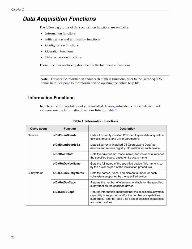
To determine the capabilities of your installed devices, subsystems on each device, and software, use the Information functions listed in Table 1.
Table 1: Information Functions
Query about Function Description
Devices olDaEnumBoards Lists all currently installed DT-Open Layers data acquisition devices, drivers, and driver parameters.
olDaEnumBoardsEx Lists all currently-installed DT-Open Layers DataAcq devices and returns registry information for each device.
olGetBoardInfo Gets the driver name, model name, and instance number of the specified board, based on its board name.
olDaGetDeviceName Gets the full name of the specified device (this name is set by the driver as part of the installation procedure).
Subsystems olDaEnumSubSystems Lists the names, types, and element number for each subsystem supported by the specified device.
olDaGetDevCaps Returns the number of elements available for the specified subsystem on the specified device.
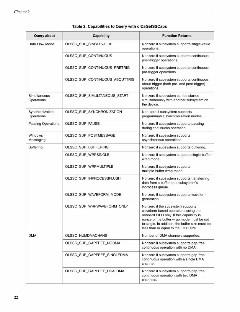
olDaGetSSCaps Returns information about whether the specified subsystem capability is supported and/or the number of capabilities supported. Refer to Table 2 for a list of possible capabilities and return values.

Function Summary
Subsystem Capability Queries
Table 2 lists the subsystem capabilities that you can query using the olDaGetSSCaps function; this function returns values as integers.
Table 3 lists the subsystem capabilities that you can query using the olDaGetSSCapsEx function; this function returns values as floating-point numbers.
Note that capabilities may be added as new devices are developed; for the most recent set of capabilities, refer to the DataAcq SDK online help.
Subsystems (cont.)
olDaGetSSCapsEx Returns information about extended subsystem capabilities. Refer to Table 3 for a list of possible capabilities and return values.
olDaEnumSSCaps Lists the possible settings for the specified subsystem capabilities, including filters, ranges, gains, resolution, and threshold channels for the start and reference trigger.
olDaGetDASSInfo Returns the subsystem type and element number of the specified subsystem with the specified device handle.
olDaIsRunning This function returns a Boolean value indicating whether the specified subsystem is currently running.
olDaGetQueueSize Returns the size of the specified queue (ready, done or inprocess) for the specified subsystem. The size indicates the number of buffers on the specified queue.
olDaEnumSSList Lists all subsystems on the simultaneous start list.
Software olDaGetDriverVersion Returns the device driver version number.
olDaGetVersion Returns the software version of the DataAcq SDK.
olDaGetErrorString Returns the string that corresponds to a device error code value.
Channels olDaEnumChannelCaps Enumerates the capabilities of a specified channel.
olDaGetChannelCaps Returns whether the capability is supported for the specified channel.
Table 1: Information Functions (cont.)
Query about Function Description
21
Chapter 2
22
Table 2: Capabilities to Query with olDaGetSSCaps
Query about Capability Function Returns
Data Flow Mode OLSSC_SUP_SINGLEVALUE Nonzero if subsystem supports single-value operations.
OLSSC_SUP_CONTINUOUS Nonzero if subsystem supports continuous post-trigger operations.
OLSSC_SUP_CONTINUOUS_PRETRIG Nonzero if subsystem supports continuous pre-trigger operations.
OLSSC_SUP_CONTINUOUS_ABOUTTRIG Nonzero if subsystem supports continuous about-trigger (both pre- and post-trigger) operations.
Simultaneous Operations
OLSSC_SUP_SIMULTANEOUS_START Nonzero if subsystem can be started simultaneously with another subsystem on the device.
Synchronization Operations
OLSSC_SUP_SYNCHRONIZATION Non-zero if subsystem supports programmable synchronization modes.
Pausing Operations OLSSC_SUP_PAUSE Nonzero if subsystem supports pausing during continuous operation.
Windows Messaging
OLSSC_SUP_POSTMESSAGE Nonzero if subsystem supports asynchronous operations.
Buffering OLSSC_SUP_BUFFERING Nonzero if subsystem supports buffering.
OLSSC_SUP_WRPSINGLE Nonzero if subsystem supports single-buffer wrap mode.
OLSSC_SUP_WRPMULTIPLE Nonzero if subsystem supports multiple-buffer wrap mode.
OLSSC_SUP_INPROCESSFLUSH Nonzero if subsystem supports transferring data from a buffer on a subsystem’s inprocess queue.
OLSSC_SUP_WAVEFORM_MODE Nonzero if subsystem supports waveform generation.
OLSSC_SUP_WRPWAVEFORM_ONLY Nonzero if the subsystem supports waveform-based operations using the onboard FIFO only. If this capability is nonzero, the buffer wrap mode must be set to single. In addition, the buffer size must be less than or equal to the FIFO size.
DMA OLSSC_NUMDMACHANS Number of DMA channels supported.
OLSSC_SUP_GAPFREE_NODMA Nonzero if subsystem supports gap-free continuous operation with no DMA.
OLSSC_SUP_GAPFREE_SINGLEDMA Nonzero if subsystem supports gap-free continuous operation with a single DMA channel.
OLSSC_SUP_GAPFREE_DUALDMA Nonzero if subsystem supports gap-free continuous operation with two DMA channels.

Function Summary
Triggered Scan Mode
OLSSC_SUP_TRIGSCAN Nonzero if subsystem supports triggered scans.
OLSSC_MAXMULTISCAN Maximum number of scans per trigger or retrigger supported by the subsystem.
OLSS_SUP_RETRIGGER_SCAN_PER_TRIGGER
Nonzero if subsystem supports scan-per-trigger triggered scan mode (retrigger is the same as the initial trigger source).
OLSS_SUP_RETRIGGER_INTERNAL Nonzero if subsystem supports internal retriggered scan mode. (retrigger source is on the device; initial trigger is any available trigger source).
OLSSC_SUP_RETRIGGER_EXTRA Nonzero if subsystem supports retrigger-extra triggered scan mode (retrigger can be any supported trigger source; initial trigger is any available trigger source).
Channel-Gain List OLSSC_CGLDEPTH Number of entries in channel-gain list.
OLSSC_SUP_RANDOM_CGL Nonzero if subsystem supports random channel-gain list setup.
OLSSC_SUP_SEQUENTIAL_CGL Nonzero if subsystem supports sequential channel-gain list setup.
OLSSC_SUP_ZEROSEQUENTIAL_CGL Nonzero if subsystem supports sequential channel-gain list setup starting with channel zero.
OLSSC_SUP_SIMULTANEOUS_SH Nonzero if subsystem supports simultaneous operations.
OLSSC_SUP_CHANNELLIST_INHIBIT Nonzero if subsystem supports channel-gain list entry inhibition.
Gain OLSSC_SUP_PROGRAMGAIN Nonzero if subsystem supports programmable gain.
OLSSC_NUMGAINS Number of gain selections.
OLSSC_NONCONTIGUOUS_CHANNELNUM
Number of random-order entries allowed in the channel-gain list.
OLSSC_SUP_SINGLEVALUE_AUTORANGE
Nonzero if subsystem supports autoranging operations.
SynchronousDigital I/O
OLSSC_SUP_SYNCHRONOUS_DIGITALIO Nonzero if subsystem supports synchronous digital output operations.
OLSSC_MAXDIGITALIOLIST_VALUE Maximum value for synchronous digital output channel list entry.
Table 2: Capabilities to Query with olDaGetSSCaps (cont.)
Query about Capability Function Returns
23

Chapter 2
24
I/O Channels OLSSC_NUMCHANNELS Number of I/O channels.
OLSSC_SUP_EXP2896 Nonzero if subsystem supports channel expansion with DT2896.
OLSSC_SUP_EXP727 Nonzero if subsystem supports channel expansion with DT727.
Channel Type OLSSC_SUP_SINGLEENDED Nonzero if subsystem supports single-ended inputs.
OLSSC_MAXSECHANS Number of single-ended channels.
OLSSC_SUP_DIFFERENTIAL Nonzero if subsystem supports differential inputs.
OLSSC_MAXDICHANS Number of differential channels.
Filters OLSSC_SUP_FILTERPERCHAN Nonzero if subsystem supports filtering per channel.
OLSSC_NUMFILTERS Number of filter selections.
OLSSC_SUP_DATA_FILTERS Nonzero if subsystem supports programmable filter types.
Ranges OLSSC_NUMRANGES Number of range selections.
OLSSC_SUP_RANGEPERCHANNEL Nonzero if subsystem supports different range settings for each channel.
OLSSC_SUP_CURRENT_OUTPUTS Non-zero if subsystem supports current outputs.
Resolution OLSSC_SUP_SWRESOLUTION Nonzero if subsystem supports software-programmable resolution.
OLSSC_NUMRESOLUTIONS Number of different resolutions that you can program for the subsystem.
Data Encoding OLSSC_SUP_BINARY Nonzero if subsystem supports binary encoding.
OLSSC_SUP_2SCOMP Nonzero if subsystem supports twos complement encoding.
OLSSC_RETURNS_FLOATS Non-zero if the subsystem returns floating-point rather than integer values.
Table 2: Capabilities to Query with olDaGetSSCaps (cont.)
Query about Capability Function Returns

Function Summary
Triggers OLSSC_SUP_SOFTTRIG Nonzero if subsystem supports an internal software trigger for the start trigger.
OLSSC_SUP_EXTERNTRIG Nonzero if subsystem supports an external digital (TTL) trigger for the start trigger.
OLSSC_SUP_SV_POS_EXTERN_TTLTRIG Nonzero if subsystem supports a positive, external digital (TTL) trigger for a single-value operation.
OLSSC_SUP_SV_NEG_EXTERN_TTLTRIG Nonzero if subsystem supports a negative, external digital (TTL) trigger for a single-value operation.
OLSSC_SUP_THRESHTRIGPOS Nonzero if subsystem supports a positive analog threshold trigger for a start trigger.
OLSSC_SUP_THRESHTRIGNEG Nonzero if subsystem supports a negative analog threshold trigger for a start trigger.
OLSSC_SUP_ANALOGEVENTTRIG Nonzero if subsystem supports analog event trigger.
OLSSC_SUP_DIGITALEVENTTRIG Nonzero if subsystem supports digital event trigger.
OLSSC_SUP_TIMEREVENTTRIG Nonzero if subsystem supports timer event trigger.
OLSSC_NUMEXTRATRIGGERS Number of extra trigger sources supported.
OLSSC_SUP_EXTERNTTLPOS_REFERENCE_TRIG
Nonzero if subsystem supports a positive, external digital (TTL) trigger for a reference trigger.
OLSSC_SUP_EXTERNTTLNEG_REFERENCE_TRIG
Nonzero if subsystem supports a negative, external digital (TTL) trigger for a reference trigger.
OLSSC_SUP_THRESHPOS_REFERENCE_TRIG
Nonzero if subsystem supports a positive threshold trigger for the reference trigger.
OLSSC_SUP_THRESHNEG_REFERENCE_TRIG
Nonzero if subsystem supports a negative threshold trigger for the reference trigger.
OLSSC_SUP_SYNCBUS_REFERNCE_TRIG
Nonzero if subsystem supports a Sync Bus trigger for the reference trigger.
OLSSC_SUP_POST_REFERENCE_TRIG_SCANCOUNT
Non-zero if subsystem supports specifying the number of samples to acquire after the reference trigger.
Table 2: Capabilities to Query with olDaGetSSCaps (cont.)
Query about Capability Function Returns
25

Chapter 2
26
Clocks OLSSC_SUP_INTCLOCK Nonzero if subsystem supports internal clock.
OLSSC_SUP_EXTCLOCK Nonzero if subsystem supports external clock.
OLSSC_NUMEXTRACLOCKS Number of extra clock sources.
OLSSC_SUP_SIMULTANEOUS_CLOCKING
Non-zero if subsystem supports simultaneous clocking of all channels.
Multiple Sensor Support
OLSSC_SUP_MULTISENSOR Non-zero if the subsystem supports multiple sensor types for each channel; otherwise, returns False.
Current OLSSC_SUP_CURRENT Non-zero if the subsystem supports current measurements; otherwise, returns False.
Resistance OLSSC_SUP_RESISTANCE Non-zero if the subsystem supports resistance measurements; otherwise, returns False.
IEPE OLSSC_SUP_IEPE Non-zero is subsystem supports IEPE (accelerometer) inputs.
OLSSC_SUP_AC_COUPLING Non-zero if subsystem supports programmable AC coupling for an IEPE input.
OLSSC_SUP_DC_COUPLING Non-zero if subsystem supports programmable DC coupling for an IEPE input.
Excitation Current Source
OLSSC_SUP_INTERNAL_EXCITATION_CURRENT_SOURCE
Non-zero if subsystem supports a programmable internal excitation current source for an IEPE input.
OLSSC_SUP_EXTERNAL_EXCITATION_CURRENT_SOURCE
Non-zero if subsystem supports a programmable external excitation current source for an IEPE input.
OLSSC_NUM_EXCITATION_CURRENT_VALUES
Number of different values for the internal excitation current source that can be programmed for the subsystem.
Table 2: Capabilities to Query with olDaGetSSCaps (cont.)
Query about Capability Function Returns

Function Summary
RTDs and Thermocouples
OLSSC_SUP_RTDS Non-zero if subsystem supports RTD inputs.
OLSSC_RETURNS_OHMS Non-zero if the subsystem can return resistance values, in Ohms.
OLSSC_SUP_THERMOCOUPLES Non-zero if subsystem supports thermocouple inputs.
OLSSC_SUP_TEMPERATURE_DATA_IN_STREAM
(Has meaning only if OLSSC_SUP_RTDS or OLSSC_SUP_THERMOCOUPLES is non-zero.) Non-zero if the device performs correction and linearization in the hardware and returns temperature values in the data stream. If zero, the device returns only raw counts and the application must perform all linearization and correction.
OLSSC_SUP_INTERLEAVED_CJC_IN_STREAM
(Has meaning only if OLSSC_SUP_TEMPERATURE_DATA_IN_STREAM is non-zero.) Non-zero if the device can optionally interleave CJC data with A/D data in the data stream.
OLSSC_SUP_CJC_SOURCE_CHANNEL (Has meaning only if OLSSC_SUP_TEMPERATURE_DATA_IN_STREAM is 0.) Non-zero if one of the analog input channels on the device is used as the CJC input.
OLSSC_SUP_CJC_SOURCE_INTERNAL (Has meaning only if OLSSC_SUP_TEMPERATURE_DATA_IN_STREAM is non-zero.) Non-zero if the CJC is measured internally on the device rather than using one of the analog input channels as the CJC input.
Thermistors OLSSC_SUP_THERMISTOR Non-zero if the subsystem supports thermistor inputs; otherwise, returns False.
Strain Gages and Bridge-Based Sensors
OLSSC_SUP_STRAIN_GAGE Non-zero if subsystem supports strain gage inputs.
OLSSC_SUP_BRIDGEBASEDSENSORS Non-zero if subsystem supports bridge-based sensor inputs.
OLSSC_SUP_SHUNT_CALIBRATION Non-zero if subsystem supports shunt calibration for strain gage and bridge-based sensors.
OLSSC_SUP_REMOTE_SENSE Non-zero if subsystem supports remote sensing for strain gage and bridge-based sensors.
OLSSC_SUP_INTERNAL_EXCITATION_VOLTAGE_SOURCE
Non-zero if subsystem supports a programmable internal excitation voltage source for strain gage and bridge-based sensors.
Table 2: Capabilities to Query with olDaGetSSCaps (cont.)
Query about Capability Function Returns
27
Chapter 2
28
Strain Gages and Bridge-Based Sensors (cont.)
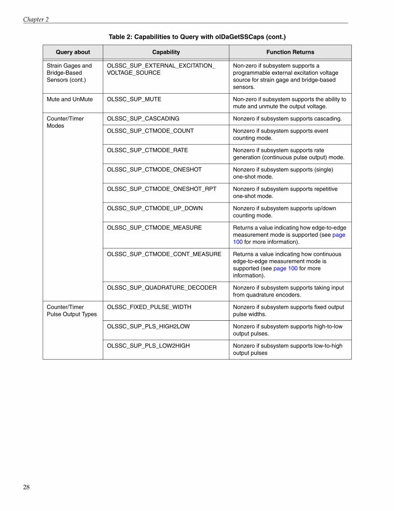
OLSSC_SUP_EXTERNAL_EXCITATION_VOLTAGE_SOURCE
Non-zero if subsystem supports a programmable external excitation voltage source for strain gage and bridge-based sensors.
Mute and UnMute OLSSC_SUP_MUTE Non-zero if subsystem supports the ability to mute and unmute the output voltage.
Counter/Timer Modes
OLSSC_SUP_CASCADING Nonzero if subsystem supports cascading.
OLSSC_SUP_CTMODE_COUNT Nonzero if subsystem supports event counting mode.
OLSSC_SUP_CTMODE_RATE Nonzero if subsystem supports rate generation (continuous pulse output) mode.
OLSSC_SUP_CTMODE_ONESHOT Nonzero if subsystem supports (single) one-shot mode.
OLSSC_SUP_CTMODE_ONESHOT_RPT Nonzero if subsystem supports repetitive one-shot mode.
OLSSC_SUP_CTMODE_UP_DOWN Nonzero if subsystem supports up/down counting mode.
OLSSC_SUP_CTMODE_MEASURE Returns a value indicating how edge-to-edge measurement mode is supported (see page 100 for more information).
OLSSC_SUP_CTMODE_CONT_MEASURE Returns a value indicating how continuous edge-to-edge measurement mode is supported (see page 100 for more information).
OLSSC_SUP_QUADRATURE_DECODER Nonzero if subsystem supports taking input from quadrature encoders.
Counter/TimerPulse Output Types
OLSSC_FIXED_PULSE_WIDTH Nonzero if subsystem supports fixed output pulse widths.
OLSSC_SUP_PLS_HIGH2LOW Nonzero if subsystem supports high-to-low output pulses.
OLSSC_SUP_PLS_LOW2HIGH Nonzero if subsystem supports low-to-high output pulses
Table 2: Capabilities to Query with olDaGetSSCaps (cont.)
Query about Capability Function Returns
Function Summary
Counter/Timer Gates
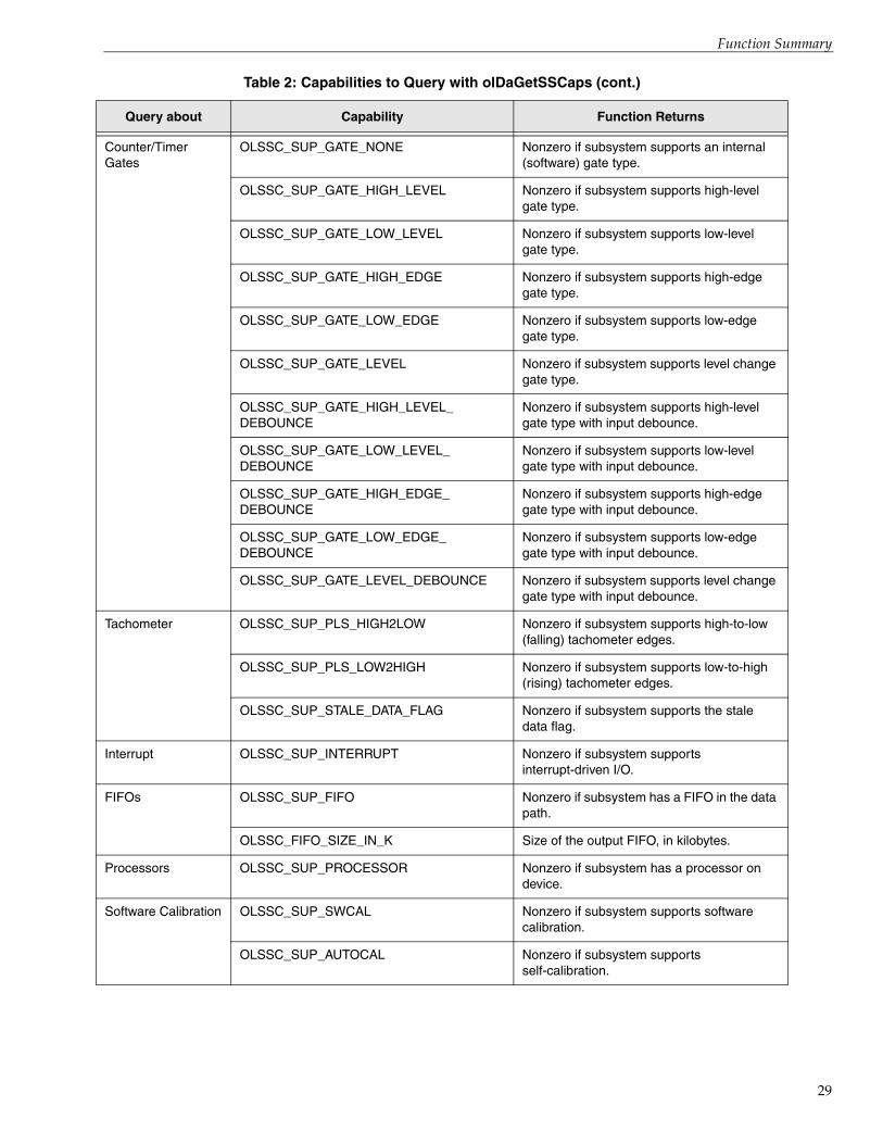
OLSSC_SUP_GATE_NONE Nonzero if subsystem supports an internal (software) gate type.
OLSSC_SUP_GATE_HIGH_LEVEL Nonzero if subsystem supports high-level gate type.
OLSSC_SUP_GATE_LOW_LEVEL Nonzero if subsystem supports low-level gate type.
OLSSC_SUP_GATE_HIGH_EDGE Nonzero if subsystem supports high-edge gate type.
OLSSC_SUP_GATE_LOW_EDGE Nonzero if subsystem supports low-edge gate type.
OLSSC_SUP_GATE_LEVEL Nonzero if subsystem supports level change gate type.
OLSSC_SUP_GATE_HIGH_LEVEL_DEBOUNCE
Nonzero if subsystem supports high-level gate type with input debounce.
OLSSC_SUP_GATE_LOW_LEVEL_DEBOUNCE
Nonzero if subsystem supports low-level gate type with input debounce.
OLSSC_SUP_GATE_HIGH_EDGE_DEBOUNCE
Nonzero if subsystem supports high-edge gate type with input debounce.
OLSSC_SUP_GATE_LOW_EDGE_DEBOUNCE
Nonzero if subsystem supports low-edge gate type with input debounce.
OLSSC_SUP_GATE_LEVEL_DEBOUNCE Nonzero if subsystem supports level change gate type with input debounce.
Tachometer OLSSC_SUP_PLS_HIGH2LOW Nonzero if subsystem supports high-to-low (falling) tachometer edges.
OLSSC_SUP_PLS_LOW2HIGH Nonzero if subsystem supports low-to-high (rising) tachometer edges.
OLSSC_SUP_STALE_DATA_FLAG Nonzero if subsystem supports the stale data flag.
Interrupt OLSSC_SUP_INTERRUPT Nonzero if subsystem supports interrupt-driven I/O.
FIFOs OLSSC_SUP_FIFO Nonzero if subsystem has a FIFO in the data path.
OLSSC_FIFO_SIZE_IN_K Size of the output FIFO, in kilobytes.
Processors OLSSC_SUP_PROCESSOR Nonzero if subsystem has a processor on device.
Software Calibration OLSSC_SUP_SWCAL Nonzero if subsystem supports software calibration.
OLSSC_SUP_AUTOCAL Nonzero if subsystem supports self-calibration.
Table 2: Capabilities to Query with olDaGetSSCaps (cont.)
Query about Capability Function Returns
29

Chapter 2
30
Initialization and Termination Functions
Once you have identified the available devices, use the Initialization functions described in Table 4.
When you are finished with your program, use the Termination functions listed in Table 5.
Table 3: Capabilities to Query with olDaGetSSCapsEx
Query about Capability Function Returns
Triggered Scan Mode OLSSCE_MAXRETRIGGER Maximum retrigger frequency supported by the subsystem.
OLSSCE_MINRETRIGGER Minimum retrigger frequency supported by the subsystem.
Clocks OLSSCE_BASECLOCK Base clock frequency supported by the subsystem.
OLSSCE_MAXCLOCKDIVIDER Maximum external clock divider supported by the subsystem.
OLSSCE_MINCLOCKDIVIDER Minimum external clock divider supported by the subsystem.
OLSSCE_MAXTHROUGHPUT Maximum throughput supported by the subsystem.
OLSSCE_MINTHROUGHPUT Minimum throughput supported by the subsystem.
Thermocouples OLSSCE_CJC_MILLIVOLTS_PER_DEGREE_C
(Has meaning only if OLSSC_SUP_THERMOCOUPLES is non-zero.) Number of millivolts per degree C for the CJC input.
Excitation Voltage OLSSC_MIN_EXCITATION_VOLTAGE The minimum value for the internal excitation voltage source that can be programmed for the subsystem.
OLSSC_MAX_EXCITATION_VOLTAGE The maximum value for the internal excitation voltage source that can be programmed for the subsystem.
Table 4: Initialization Functions
Function Description
olDaInitialize Provides the means for the software to associate specific requests with a particular device; it must be called before any other function. This function loads a specified device's software support and provides a “device handle” value. This value is used to identify the device, and must be supplied as an argument in all subsequent function calls that reference the device.
olDaGetDASS Allocates a subsystem for use by returning a handle to the subsystem.
Function Summary
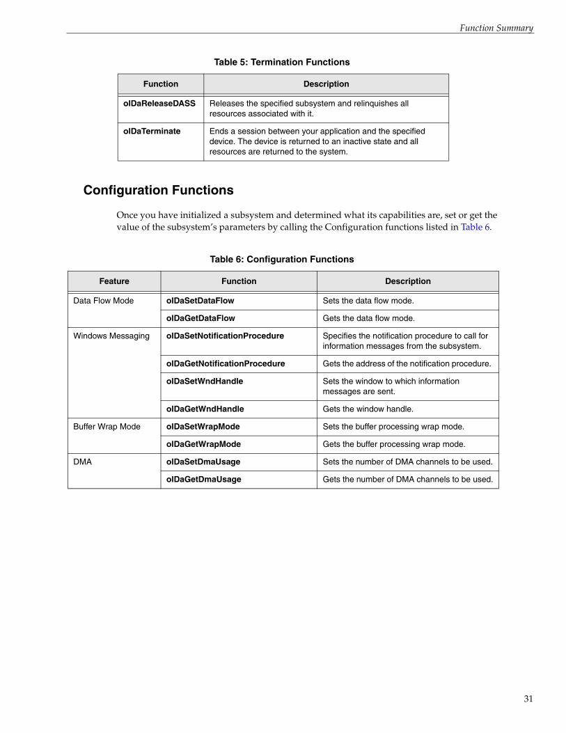
Configuration Functions
Once you have initialized a subsystem and determined what its capabilities are, set or get the value of the subsystem’s parameters by calling the Configuration functions listed in Table 6.
Table 5: Termination Functions
Function Description
olDaReleaseDASS Releases the specified subsystem and relinquishes all resources associated with it.
olDaTerminate Ends a session between your application and the specified device. The device is returned to an inactive state and all resources are returned to the system.
Table 6: Configuration Functions
Feature Function Description
Data Flow Mode olDaSetDataFlow Sets the data flow mode.
olDaGetDataFlow Gets the data flow mode.
Windows Messaging olDaSetNotificationProcedure Specifies the notification procedure to call for information messages from the subsystem.
olDaGetNotificationProcedure Gets the address of the notification procedure.
olDaSetWndHandle Sets the window to which information messages are sent.
olDaGetWndHandle Gets the window handle.
Buffer Wrap Mode olDaSetWrapMode Sets the buffer processing wrap mode.
olDaGetWrapMode Gets the buffer processing wrap mode.
DMA olDaSetDmaUsage Sets the number of DMA channels to be used.
olDaGetDmaUsage Gets the number of DMA channels to be used.
31

Chapter 2
32
Triggered Scans olDaSetTriggeredScanUsage Enables or disables triggered scan mode.
olDaGetTriggeredScanUsage Gets the triggered scan mode setting.
olDaSetMultiscanCount Sets the number of times to scan per trigger/retrigger.
olDaGetMultiscanCount Gets the number of times to scan per trigger/retrigger.
olDaSetRetriggerMode Sets the retrigger mode.
olDaGetRetriggerMode Gets the retrigger mode.
olDaSetRetriggerFrequency Sets the frequency of the internal retrigger when using internal retrigger mode.
olDaGetRetriggerFrequency Gets the frequency of the internal retrigger when using internal retrigger mode.
Channel-Gain List olDaSetChannelListSize Sets the size of the channel-gain list.
olDaGetChannelListSize Gets the size of the channel-gain list.
olDaSetChannelListEntry Sets the channel number of a channel-gain list entry.
olDaGetChannelListEntry Gets the channel number of a channel-gain list entry.
olDaSetGainListEntry Sets a gain value for a channel-gain list entry.
olDaGetGainListEntry Gets the gain value of a channel-gain list entry.
olDaSetChannelListEntryInhibit Enables/disables channel entry inhibition for a channel-gain list entry.
olDaGetChannelListEntryInhibit Gets the channel entry inhibition setting of a channel-gain list entry.
olDaSetDigitalIOListEntry Sets the digital value to output for the channel-gain list entry.
olDaGetDigitalIOListEntry Gets the digital value to output for the channel-gain list entry.
SynchronousDigital I/O
olDaSetSynchronousDigitalIOUsage Enables or disables synchronous digital I/O operations.
olDaGetSynchronousDigitalIOUsage Gets the synchronous digitalI/O setting.
Channel Type olDaSetChannelType Sets the channel configuration type of a channel.
olDaGetChannelType Gets the channel configuration type of a channel.
Table 6: Configuration Functions (cont.)
Feature Function Description

Function Summary
Filters olDaSetChannelFilter Sets the filter cut-off frequency for a channel.
olDaGetChannelFilter Gets the filter cut-off frequency for a channel.
olDaSetDataFilterType Sets the filter type for a subsystem that supports programmable filter types.
olDaGetDataFilterType Gets the filter type for a subsystems that support programmable filters.
Ranges olDaSetRange Sets the voltage range for a subsystem.
olDaGetRange Gets the voltage range for a subsystem.
olDaSetChannelRange Sets the voltage range for a channel.
olDaGetChannelRange Gets the voltage range for a channel.
Resolution olDaSetResolution Sets the number of bits of resolution.
olDaGetResolution Gets the number of bits of resolution.
Data Encoding olDaSetEncoding Sets the data encoding type.
olDaGetEncoding Gets the data encoding type.
Triggers olDaSetTrigger Sets the trigger source used for the start trigger.
olDaGetTrigger Gets the trigger source used for the start trigger.
olDaSetTriggerThresholdChannel Sets the number of the channel that is monitored for the start trigger event (OL_TRG_THRESHPOS or OL_TRG_THRESHNEG).
olDaGetTriggerThresholdChannel Gets the number of the channel that is monitored for the start trigger event (OL_TRG_THRESHPOS or OL_TRG_THRESHNEG).
olDaSetTriggerThresholdLevel Sets the threshold level for the start threshold trigger.
olDaGetTriggerThresholdLevel Gets the threshold level for the start threshold trigger.
olDaSetReferenceTrigger Sets the trigger source used for the reference trigger.
olDaGetReferenceTrigger Gets the trigger source used for the reference trigger.
Table 6: Configuration Functions (cont.)
Feature Function Description
33

Chapter 2
34
Triggers (cont.) olDaSetReferenceTriggerThresholdChannel
Sets the number of the channel that is monitored for the reference trigger event (OL_REFERENCE_TRG_THRESHPOS or OL_REFERENCE_TRG_THRESHNEG).
olDaGetReferenceTriggerThresholdChannel
Gets the number of the channel that is monitored for the reference trigger event (OL_REFERENCE_TRG_THRESHPOS or OL_REFERENCE_TRG_THRESHNEG).
olDaSetReferenceTriggerThresholdLevel
Sets the threshold level for the reference threshold trigger.
olDaGetReferenceTriggerThresholdLevel
Gets the threshold level for the reference threshold trigger.
olDaSetReferenceTriggerPostScanCount
Sets the number of samples per channel to acquire after the reference trigger event occurs.
olDaGetReferenceTriggerPostScanCount
Gets the number of samples per channel to acquire after the reference trigger event occurs.
olDaSetPretriggerSource Sets the pre-trigger source.
olDaGetPretriggerSource Gets the pre-trigger source.
olDaSetRetrigger Sets the retrigger source for retrigger-extra retrigger mode.
olDaGetRetrigger Gets the retrigger source for retrigger-extra retrigger mode.
Clocks olDaSetClockSource Sets the clock source.
olDaGetClockSource Gets the clock source.
olDaSetClockFrequency Sets the frequency of the internal clock or a counter/timer’s output frequency.
olDaGetClockFrequency Gets the frequency of the internal clock or a counter/timer’s output frequency.
olDaSetExternalClockDivider Sets the input divider value of the external clock.
olDaGetExternalClockDivider Gets the input divider value of the external clock.
Multiple Sensor Types olDaSetMultiSensorType Sets the measurement type for the specified channel.
olDaGetMultiSensorType Gets the measurement type for the specified channel.
Table 6: Configuration Functions (cont.)
Feature Function Description

Function Summary
IEPE Support olDaSetCouplingType Sets the coupling type to use or the specified channel.
olDaGetCouplingType Gets the coupling type that is used by the specified channel.
olDaSetExcitationCurrentSource Sets the excitation current source for the specified channel.
olDaGetExcitationCurrentSource Gets the excitation current source that is used by the specified channel.
olDaSetExcitationCurrentValue Sets the value of the internal excitation current source to use for the specified channel.
olDaGetExcitationCurrentValue Gets the value of the internal excitation current source that is used by the specified channel.
Strain Gage and Bridge-Based Sensor Support
olDaSetStrainBridgeConfiguration Sets the configuration of the strain gage for the channel.
olDaGetStrainBridgeConfiguraiton Gets the configuration of the strain gage for the channel.
olDaSetBridgeConfiguration Sets the configuration of the bridge-based sensor for the channel.
olDaGetBridgeConfiguraiton Gets the configuration of the bridge-based sensor for the channel.
olDaSetStrainExcitationVoltageSource
Sets the excitation voltage source for the subsystem.
olDaGetStrainExcitationVoltageSource
Gets the excitation voltage source for the subsystem.
olDaSetStrainExcitationVoltage Sets the value of the internal excitation voltage source to use for the subsystem.
olDaGetStrainExcitationVoltage Gets the value of the internal excitation voltage source to use for the subsystem.
olDaSetStrainShuntResistor Specifies whether the shunt resistor for the channel is enabled or disabled.
olDaGetStrainShuntResistor Returns whether the shunt resistor for the channel is enabled or disabled.
RTDs olDaSetRtdType Sets the type of RTD to use for the input channel of the specified subsystem.
olDaGetRtdType Gets the currently configured RTD type for the input channel of the specified subsystem.
olDaSetRtdR0 Sets the nominal resistance of the RTD, in ohms at 0 degrees C, for the specified channel.
olDaGetRtdR0 Gets the nominal resistance of the RTD, in ohms at 0 degrees C, for the specified channel.
Table 6: Configuration Functions (cont.)
Feature Function Description
35

Chapter 2
36
RTDs (cont.) olDaSetRtdA Sets the A coefficient for the RTD that is connected to the specified channel.
olDaGetRtdA Gets the A coefficient for the RTD that is connected to the specified channel.
olDaSetRtdB Sets the B coefficient for the RTD that is connected to the specified channel.
olDaGetRtdB Gets the B coefficient for the RTD that is connected to the specified channel.
olDaSetRtdC Sets the C coefficient for the RTD that is connected to the specified channel.
olDaGetRtdC Gets the C coefficient for the RTD that is connected to the specified channel.
Thermocouples olDaSetThermocoupleType Sets the type of thermocouple to use for the input channel of the specified subsystem.
olDaGetThermocoupleType Gets the currently configured thermocouple type for the input channel of the specified subsystem.
olDaSetReturnCjcTemperatureInStream
Enables or disables the specified subsystem from returning CJC values in the data stream.
olDaGetReturnCjcTemperatureInStream
Returns whether the specified subsystem has been enabled or disabled from returning CJC values in the data stream.
Thermistors olDaSetThermistorA Sets the A coefficient for the thermistor that is connected to the specified channel.
olDaGetThermistorA Gets the A coefficient for the thermistor that is connected to the specified channel.
olDaSetThermistorB Sets the B coefficient for the thermistor that is connected to the specified channel.
olDaGetThermistorB Gets the B coefficient for the thermistor that is connected to the specified channel.
olDaSetThermistorC Sets the C coefficient for the thermistor that is connected to the specified channel.
olDaGetThermistorC Gets the C coefficient for the thermistor that is connected to the specified channel.
Sensor Wiring Configuration
olDaSetSensorWiringConfiguration Sets the wiring configuration (two-wire, three-wire, or four-wire) for the specified channel.
olDaGetSensorWiringConfiguration Gets the wiring configuration (two-wire, three-wire, or four-wire) for the specified channel.
Table 6: Configuration Functions (cont.)
Feature Function Description

Function Summary
Input Termination Resistor
olDaSetInputTerminationEnabled Sets the state of the input termination resistor for the specified channel.
olDaGetInputTerminationEnabled Gets the state of the input termination resistor for the specified channel.
Sync Mode olDaSetSyncMode Sets the synchronization mode for devices that provide a synchronization connector.
olDaGetSyncMode Gets the synchronization mode for devices that provide a synchronization connector.
Counter/Timers olDaSetCTMode Sets the counter/timer mode.
olDaGetCTMode Gets the counter/timer mode.
olDaSetCascadeMode Sets the counter/timer cascade mode.
olDaGetCascadeMode Gets the counter/timer cascade mode.
olDaSetGateType Sets the gate type for the counter/timer mode.
olDaGetGateType Gets the gate type for the counter/timer mode.
olDaSetPulseType Sets the pulse type for the counter/timer mode.
olDaGetPulseType Gets the pulse type for the counter/timer mode.
olDaSetPulseWidth Sets the pulse output width for the counter/timer mode.
olDaGetPulseWidth Gets the pulse width for the counter/timer mode.
olDaSetMeasureStartEdge Sets the start edge for edge-to-edge measurement operations.
olDaGetMeasureStartEdge Gets the start edge for edge-to-edge measurement operations.
olDaSetMeasureStopEdge Sets the stop edge for edge-to-edge measurement operations.
olDaGetMeasureStopEdge Gets the stop edge for edge-to-edge measurement operations.
olDaSetQuadDecoder Sets various aspects of a quadrature decoder.
Table 6: Configuration Functions (cont.)
Feature Function Description
37

Chapter 2
38
Tachometer olDaSetEdgeType Sets the edge type (Falling or Rising) for the tachometer subsystem.
olDaGetEdgeType Gets the edge type (Falling or Rising) for the tachometer subsystem.
olDaSetStaleDataFlagEnabled Sets the flag indicating whether or not the value of the tachometer is new.
If StaleDataFlagEnabled is True, the most significant bit (MSB) of the value is set to 0 to indicate new data; reading the value before the measurement is complete returns an MSB of 1.
If the StaleDataFlagEnabled is False, the MSB is always set to 0.
olDaGetStaleDataFlagEnabled Gets the flag indicating whether or not the value of the tachometer is new.
If StaleDataFlagEnabled is True, the most significant bit (MSB) of the value is set to 0 to indicate new data; reading the value before the measurement is complete returns an MSB of 1.
If the StaleDataFlagEnabled is False, the MSB is always set to 0.
Table 6: Configuration Functions (cont.)
Feature Function Description

Function Summary
Operation Functions
Once you have set the parameters of a subsystem, use the Operation functions listed inTable 7.
Table 7: Operation Functions
Operation Function Description
Single-Value Operations olDaGetSingleValue Reads a single input value from the specified channel of a subsystem (using a specified gain), and returns the data as a 32-bit integer (long).
olDaGetSingleValues For subsystems that support simultaneous operations, reads a single input value from all of the input channels of the specified subsystem (using a specified gain), and returns the data as 32-bit integers (longs).
olDaGetSingleFloat Reads a single input value from the specified channel of a subsystem (using a specified gain) and returns the data as a floating-point value.
olDaGetSingleFloats For subsystems that support simultaneous operations, reads a single input value from all of the input channels of the specified subsystem (using the specified gain), and returns the data as floating-point values.
olDaGetCjcTemperature Reads the CJC temperature of an input channel on the specified subsystem, and returns the temperature, in degrees C, as a floating-point value.
olDaGetCjcTemperatures For subsystems that support simultaneous operations, this function reads the CJC temperature of each input channel on the specified subsystem, and returns the temperatures, in degrees C, as floating-point values.
olDaGetSingleValueEx Determines the appropriate gain for the range (called autoranging), if desired, reads a single input value from the specified subsystem channel, and returns the value as both a code and a voltage.
olDaPutSingleValue Writes a single output value to the specified channel of a subsystem.
olDaPutSingleValues For subsystems that support simultaneous operations, writes a single value to each output channel of the specified subsystem.
Configure Operation olDaConfig After setting up a specified subsystem using the configuration functions, configures the subsystem with new parameter values.
39

Chapter 2
40
Start/Stop Operations olDaStart Starts the operation for which the subsystem has been configured.
olDaPause Pauses a continuous operation on the subsystem.
olDaContinue Continues the previously paused operation on the subsystem.
olDaStop Stops the operation and returns the subsystem to the ready state.
olDaAbor Stops the subsystem’s operation immediately.
olDaReset Causes the operation to terminate immediately, and re-initializes the subsystem.
Mute and Unmute Operations
olDaMute Attenuates the output voltage of the subsystem to 0 V over a hardware-dependent number of samples.
olDaUnMute Returns the output voltage of the subsystem to its current level over a hardware-dependent number of samples.
Calibration Operations olDaAutoCalibrate Initiates the internal self-calibration process of the specified subsystem, if supported by the device.
Buffer Operations olDaGetBuffer Gets a completed buffer from the done queue of the specified subsystem.
olDaPutBuffer Assigns a data buffer for the subsystem to the ready queue.
olDaFlushBuffers Transfers all data buffers held by the subsystem to the done queue.
olDaFlushFromBufferInprocess Copies all valid samples, up to a given number of samples, from the inprocess buffer to a specified buffer. It also sets the logical size of the buffer with flushed data to the number of samples copied and places the inprocess buffer on the done queue when it has been filled with the remaining samples.
Counter/Timer Operations olDaReadEvents Gets the number of events that have been counted since the subsystem was started with olDaStart.
olDaMeasureFrequency Measures the frequency of the input clock source for the selected counter/timer.
Table 7: Operation Functions (cont.)
Operation Function Description

Function Summary
Data Conversion Functions
Once you have acquired data, you can use the functions listed in Table 8 to convert the data, if desired.
Simultaneous Operations olDaGetSSList Gets a handle to a simultaneous start list.
olDaPutDassToSSList Puts the specified subsystem on the simultaneous start list.
olDaSimultaneousPreStart Simultaneously prestarts (performs setup operations on) all subsystems on the specified simultaneous start list.
olDaSimultaneousStart Simultaneously starts all subsystems on the specified simultaneous start list.
olDaReleaseSSList Releases the specified simultaneous start list and relinquishes all resources associated with it.
Table 8: Data Conversion Functions
Function Description
olDaCodeToVolts Converts a code value to voltage value, using the range, gain, resolution, and encoding you specify.
olDaVoltsToCode Converts a voltage value to code value, using the range, gain, resolution, and encoding you specify.
olDaVoltsToStrain Converts a raw A/D count value to a strain value based on the specified configuration.
olDaVoltsToBridgeBasedSensor Converts a raw A/D count value to a value for a bridge-based sensor based on the specified configuration.
Table 7: Operation Functions (cont.)
Operation Function Description
41

Chapter 2
42
Data Management FunctionsData management functions link the various layers of the DT-Open Layers architecture together. The fundamental data object in the DataAcq SDK is a buffer. All functions that create, manipulate, and delete buffers are encapsulated in the data management portion of the DataAcq SDK.
The following groups of data management functions are available:
• Buffer management functions
• List management functions
The following subsections summarize these functions.
Note: For specific information about each of these functions, refer to the DataAcq SDK online help. See page 15 for information on launching the online help file.
Buffer Management Functions
The Buffer Management functions, listed in Table 9, are a set of object-oriented tools intended for both application and system programmers. When a buffer object is created, a buffer handle (HBUF) is returned. This handle is used in all subsequent buffer manipulation.
Table 9: Buffer Management Functions
Function Description
olDmAllocBuffer Creates a buffer object of a specified number of samples, where each sample is 2 bytes.
olDmCallocBuffer Creates a buffer object of a specified number of samples of a specified size.
olDmCopyBuffer Copies data from the buffer to the specified array.
olDmCopyFromBuffer Copies data from the buffer to the specified array.
olDmCopyToBuffer Copies data from the specified array to the buffer.
olDmFreeBuffer Deletes a buffer object.
olDmGetBufferPtr Gets a pointer to the buffer data.
olDmGetBufferSize Gets the physical buffer size (in bytes).
olDmGetDataBits Gets the number of valid data bits.
olDmSetDataBits Sets the number of valid data bits.
olDmSetDataWidth Sets the width of each data sample.
olDmGetDataWidth Gets the width of each data sample.
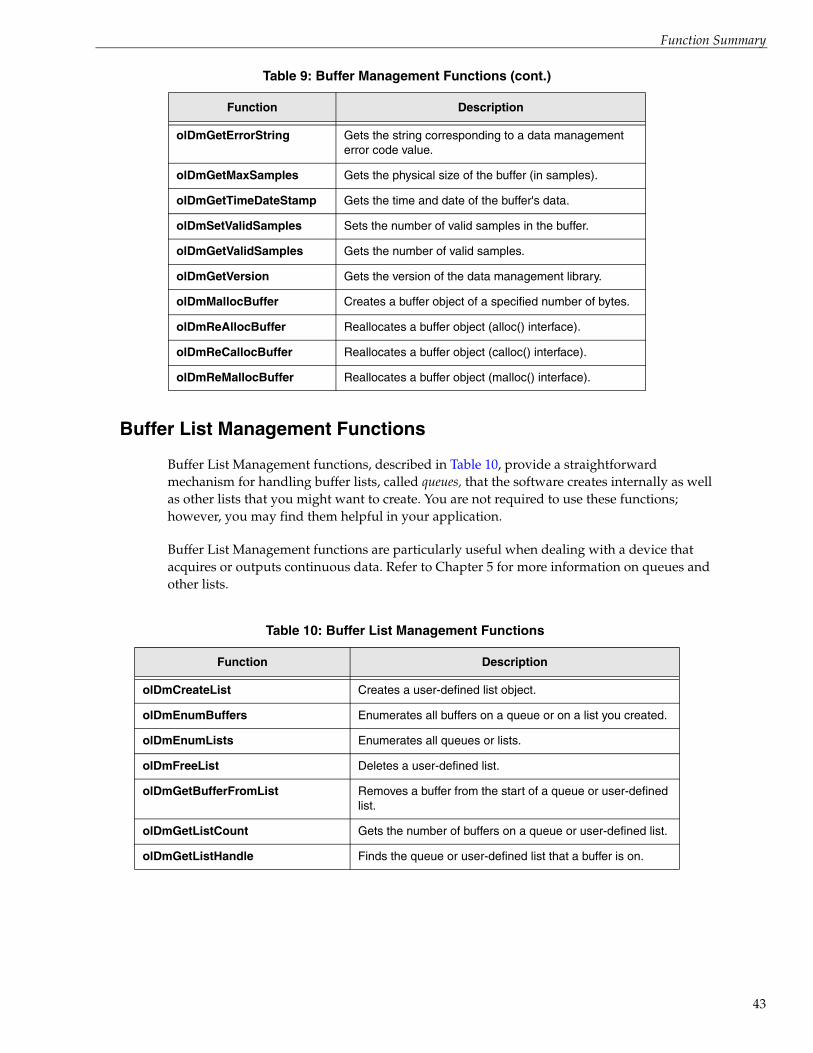
Function Summary
Buffer List Management Functions
Buffer List Management functions, described in Table 10, provide a straightforward mechanism for handling buffer lists, called queues, that the software creates internally as well as other lists that you might want to create. You are not required to use these functions; however, you may find them helpful in your application.
Buffer List Management functions are particularly useful when dealing with a device that acquires or outputs continuous data. Refer to Chapter 5 for more information on queues and other lists.
olDmGetErrorString Gets the string corresponding to a data management error code value.
olDmGetMaxSamples Gets the physical size of the buffer (in samples).
olDmGetTimeDateStamp Gets the time and date of the buffer's data.
olDmSetValidSamples Sets the number of valid samples in the buffer.
olDmGetValidSamples Gets the number of valid samples.
olDmGetVersion Gets the version of the data management library.
olDmMallocBuffer Creates a buffer object of a specified number of bytes.
olDmReAllocBuffer Reallocates a buffer object (alloc() interface).
olDmReCallocBuffer Reallocates a buffer object (calloc() interface).
olDmReMallocBuffer Reallocates a buffer object (malloc() interface).
Table 10: Buffer List Management Functions
Function Description
olDmCreateList Creates a user-defined list object.
olDmEnumBuffers Enumerates all buffers on a queue or on a list you created.
olDmEnumLists Enumerates all queues or lists.
olDmFreeList Deletes a user-defined list.
olDmGetBufferFromList Removes a buffer from the start of a queue or user-defined list.
olDmGetListCount Gets the number of buffers on a queue or user-defined list.
olDmGetListHandle Finds the queue or user-defined list that a buffer is on.
Table 9: Buffer Management Functions (cont.)
Function Description
43

Chapter 2
44
olDmGetListIds Gets a description of the queue or list.
olDmPeekBufferFromList Gets the handle of the first buffer in the queue or list but does not remove the buffer from the queue or list.
olDmPutBufferToList Adds a buffer to the end of a queue or list.
Table 10: Buffer List Management Functions (cont.)
Function Description

3Using the DataAcq SDK
System Operations . . . . . . . . . . . . . . . . . . . . . . . . . . . . . . . . . . . . . . . . . . . . . . . . . . . . . . . . . . . . 47
Analog and Digital I/O Operations . . . . . . . . . . . . . . . . . . . . . . . . . . . . . . . . . . . . . . . . . . . . . 50
Counter/Timer Operations. . . . . . . . . . . . . . . . . . . . . . . . . . . . . . . . . . . . . . . . . . . . . . . . . . . . . 94
Measure Counter Operations . . . . . . . . . . . . . . . . . . . . . . . . . . . . . . . . . . . . . . . . . . . . . . . . . . 119
Quadrature Decoder Operations . . . . . . . . . . . . . . . . . . . . . . . . . . . . . . . . . . . . . . . . . . . . . . . 123
Tachometer Operations . . . . . . . . . . . . . . . . . . . . . . . . . . . . . . . . . . . . . . . . . . . . . . . . . . . . . . . 124
Simultaneous Startup. . . . . . . . . . . . . . . . . . . . . . . . . . . . . . . . . . . . . . . . . . . . . . . . . . . . . . . . . 126
45

Chapter 3
46
This chapter provides conceptual information to describe the following operations provided by the DataAcq SDK:
• System operations, described starting on page 47
• Analog and digital I/O operations, described starting on page 50
• Counter/timer operations, described starting on page 94
• Simultaneous startup, described starting on page 126
Use this information with the reference information provided in the DataAcq SDK online help when programming your data acquisition devices; refer to page 15 for more information on launching this help file.

Using the DataAcq SDK
System OperationsThe DataAcq SDK provides functions for the following general system operations:
• Initializing a device
• Specifying a subsystem
• Configuring a subsystem
• Calibrating a subsystem
• Handling errors
• Handling messages
• Releasing a subsystem and driver
The following subsections describe these operations in more detail.
Initializing a Device
To perform a data acquisition operation, your application program must initialize the device driver for the device you are using with the olDaInitialize function. This function returns a device handle, called HDEV. You need one device handle for each device. Device handles allow you to access more than one device in your system.
If you are unsure of the DT-Open Layers devices in your system, use the olDaEnumBoards function, which lists the device name, device driver name, and system resources used by each DT-Open Layers device in your system, or the olDaGetBoardInfo function, which returns the driver name, model name, and instance number of the specified board, based on its board name.
Once you have initialized a device, you can specify a subsystem, as described in the next section.
Specifying a Subsystem
The DataAcq SDK allows you to define the following subsystems:
• Analog input (A/D subsystem)
• Analog output (D/A subsystem)
• Digital input (DIN subsystem)
• Digital output (DOUT subsystem)
• Counter/timer (C/T subsystem)
• Tachometer (TACH subsystem)
47

Chapter 3
48
A device can have multiple elements of the same subsystem type. Each of these elements is a subsystem of its own and is identified by a subsystem type and element number. Element numbering is zero-based; that is, the first instance of the subsystem is called element 0, the second instance of the subsystem is called element 1, and so on. For example if two digital I/O ports are on your device, two DIN or DOUT subsystems are available, differentiated as element 0 and element 1.
Once you have initialized the device driver for the specified device, you must specify the subsystem/element on the specified device using the olDaGetDASS function. This function returns a subsystem handle, called HDASS. To access a subsystem, you need one subsystem handle for each subsystem. Subsystem handles allow you to access more than one subsystem on a device.
If you are unsure of the subsystems on a device, use the olDaEnumSubSystems or olDaGetDevCaps function. olDaEnumSubSystems lists the names, types, and number of elements for all subsystems supported by the specified device. olDaGetDevCaps returns the number of elements for a specified subsystem type on a specified device.
Note: You can call any function that contains HDASS as a parameter for any subsystem. In some cases, however, the subsystem may not support the particular capability. If this occurs, the subsystem returns an error code indicating that it does not support that function.
Once you have specified a subsystem/element, you can configure the subsystem and perform a data acquisition operation, as described in the following section.
Configuring a Subsystem
You configure a subsystem by setting its parameters or capabilities. For more information on the capabilities you can query and specify, refer to the following:
• For analog and digital I/O operations, refer to page 50
• For the counter/timer operations, refer to page 94
• For tachometer operations, refer to page 119
• For quadrature decoder operations, refer to page 123
• For simultaneous operations, refer to page 126
Once you have set up the parameters appropriately for the operation you want to perform, call the olDaConfig function to configure the parameters before performing the operation.
Calibrating a Subsystem
Some devices provide an self-calibrating feature, where a specified subsystem performs an auto-zero function. To determine if the specified subsystem supports this capability, call the olDaGetSSCaps function, specifying the capability OLSSC_SUP_AUTOCAL. If this function returns a nonzero value, the capability is supported.

Using the DataAcq SDK
To calibrate the subsystem, call the olDaAutoCalibrate function. Note that the subsystem must be stopped before calling this function, or an error is returned.
Handling Errors
An error code is returned by each function in the DataAcq SDK. An error code of 0 indicates that the function executed successfully (no error). Any other error code indicates that an error occurred. Your application program should check the value returned by each function and perform the appropriate action if an error occurs.
Refer to the DataAcq SDK online help for detailed information on the returned error codes and how to proceed should they occur.
Handling Messages
The data acquisition device notifies your application of buffer movement and other events by generating messages.
To determine if the subsystem can post messages, use the olDaGetSSCaps function, specifying the capability OLSSC_SUP_POSTMESSAGE. If this function returns a nonzero value, the capability is supported.
Specify the window to receive messages using the olDaSetWndHandle function or the procedure to handle these messages using the olDaSetNotificationProcedure function.
Note: The lParam parameter specified in this call is included in all messages, except in the case of an OLDA_WM_IO_COMPLETE, OLDA_WM_EVENT_DONE, or OLDA_WM_MEASURE_DONE message where the value of lParam is device-dependent. Refer to page 89 for more information on these messages.
Refer to the DataAcq SDK online help for more information on the messages that can be generated and how to proceed should they occur.
Releasing the Subsystem and the Driver
When you are finished performing data acquisition operations, release the simultaneous start list, if used, using the olDaReleaseSSList function. Then, release each subsystem using the olDaReleaseDASS function. Release the driver and terminate the session using the olDaTerminate function.
49

Chapter 3
50
Analog and Digital I/O Operations The DataAcq SDK defines the following capabilities that you can query and/or specify for analog and/or digital I/O operations:
• Channels (including channel type, channel list, channel inhibit list, and synchronous digital I/O list)
• Multisensor inputs
• Voltage inputs
• Current measurements
• Resistance measurements
• IEPE sensor inputs
• Thermocouple inputs
• RTD inputs
• Thermistor inputs
• Strain gage and bridge-based sensor inputs
• Data encoding
• Resolution
• Ranges
• Gains
• Filters
• Data flow modes
• Triggered scan mode
• Interrupts
• Clock sources
• Trigger sources
• Post trigger count
• Synchronization mode
• Buffers
• DMA resources
The following subsections describe these capabilities in more detail.
Channels
Each subsystem (or element of a subsystem type) can have multiple channels. To determine how many channels the subsystem supports, use the olDaGetSSCaps function, specifying the OLSSC_NUMCHANNELS capability.

Using the DataAcq SDK
Some subsystems on the DT2896 and DT727 devices also provide channel expansion. To determine if the subsystem supports channel expansion, use the olDaGetSSCaps function, specifying the OLSSC_SUP_EXP2896 capability (for the DT2896) or the OLSSC_SUP_EXP727 capability (for the DT727). If this function returns a nonzero value, the capability is supported.
Specifying the Channel Type
The DataAcq SDK supports the following channel types:
• Single-ended – Use this configuration when you want to measure high-level signals, noise is insignificant, the source of the input is close to the device, and all the input signals are referred to the same common ground.
To determine if the subsystem supports the single-ended channel type, use the olDaGetSSCaps function, specifying the OLSSC_SUP_SINGLEENDED capability. If this function returns a nonzero value, the capability is supported.
To determine how many single-ended channels are supported by the subsystem, use the olDaGetSSCaps function, specifying the OLSSC_MAXSECHANS capability.
Specify the channel type as single-ended for each channel using the olDaSetChannelType function.
• Differential – Use this configuration when you want to measure low-level signals (less than 1 V), you are using an A/D converter with high resolution (greater than 12 bits), noise is a significant part of the signal, or common-mode voltage exists.
To determine if the subsystem supports the differential channel type, use the olDaGetSSCaps function, specifying the OLSSC_SUP_DIFFERENTIAL capability. If this function returns a nonzero value, the capability is supported.
To determine how many differential channels are supported by the subsystem, use the olDaGetSSCaps function, specifying the OLSSC_MAXDICHANS capability.
Specify the channel type as differential for each channel using the olDaSetChannelType function.
Note: For pseudo-differential analog inputs, specify the single-ended channel type; in this case, how you wire these signals determines the configuration. This option provides less noise rejection than the differential configuration, but twice as many analog input channels.
For older model devices, this setting is jumper-selectable and must be specified in the driver configuration dialog.
The channel list is not used to set the channel type.
The following subsections describe how to specify channels.
51

Chapter 3
52
Specifying a Single Channel
The simplest way to acquire data from or output data to a single channel is to specify the channel for a single-value operation; refer to page 69 for more information on single-value operations.
You can also specify a single channel using a channel list, described in the next section.
Specifying One or More Channels
You acquire data from or output data to one or more channels using a channel list.
The DataAcq SDK provides features that allow you to group the channels in the list sequentially (either starting with 0 or with any other analog input channel) or randomly. In addition, the DataAcq SDK allows you to specify a single channel or the same channel more than once in the list. Your device, however, may limit the order in which you can enter a channel in the channel list.
To determine how the channels can be ordered in the channel list for your subsystem, use the olDaGetSSCaps function, specifying the OLSSC_RANDOM_CGL capability. If this function returns a nonzero value, the capability is supported; you can order the channels in the channel list in any order, starting with any channel.
If this capability is not supported, use the olDaGetSSCaps function, specifying the OLSSC_SUP_SEQUENTIAL_CGL capability. If this function returns a nonzero value, the capability is supported; you must order the channels in the channel list in sequential order, starting with any channel.
If this capability is not supported, use the olDaGetSSCaps function, specifying the OLSSC_SUP_ZEROSEQUENTIAL_CGL capability. If this function returns a nonzero value, the capability is supported; you must order the channels in the channel list in sequential order, starting with channel 0.
To determine if the subsystem supports simultaneous sample-and-hold mode use the olDaGetSSCaps function, specifying the OLSSC_SUP_SIMULTANEOUS_SH capability. If this function returns a nonzero value, the capability is supported. You must enter at least two channels in the channel list. Generally, the first channel is the sample channel and the remaining channels are the hold channels.
The following subsections describe how to specify channels in a channel list.
Specifying the Channel List Size
To determine the maximum size of the channel list for the subsystem, use the olDaGetSSCaps function, specifying the OLSSC_CGLDEPTH capability.
Use the olDaSetChannelListSize function to specify the size of the channel list.

Using the DataAcq SDK
Note: The OLSSC_CGLDEPTH capability specifies the maximum size of the channel list, channel inhibit list, synchronous digital I/O list, and gain list.
Specifying the Channels in the Channel List
Use the olDaSetChannelListEntry function to specify the channels in the channel list in the order you want to sample them or output data from them. (For simultaneous sampling modules, order does not matter, and you cannot enter a particular channel more than once.)
The channels are sampled or output in order from the first entry to the last entry in the channel list. Channel numbering is zero-based; that is, the first entry in the channel list is entry 0, the second entry is entry 1, and so on.
For example, if you want to sample channel 4 twice as frequently as channels 5 and 6, you could program the channel list as follows:
In this example, channel 4 is sampled first, followed by channel 5, channel 4 again, and then channel 6.
Inhibiting Channels in the Channel List
If supported, you can set up a channel-inhibit list; this feature is useful if you want to discard values acquired from specific channels, as is typical in simultaneous sample-and-hold applications.
To determine if a subsystem supports a channel-inhibit list, use the olDaGetSSCaps function, specifying the OLSSC_SUP_CHANNELLIST_INHIBIT capability. If this function returns a nonzero value, the capability is supported.
Using the olDaSetChannelListEntryInhibit function, you can enable or disable inhibition for each entry in the channel list. If enabled, the acquired value is discarded after the channel entry is sampled; if disabled, the acquired value is stored after the channel entry is sampled.
In the following example, the values acquired from channels 11 and 9 are discarded and the values acquired from channels 10 and 8 are stored.
Channel-List Entry Channel Description
0 4 Sample channel 4.
1 5 Sample channel 5.
2 4 Sample channel 4 again.
3 6 Sample channel 6.
53

Chapter 3
54
Specifying Synchronous Digital I/O Values in the Channel List
If supported, you can set up a synchronous digital I/O list; this feature is useful if you want to write a digital output value to dynamic digital output channels when an analog input channel is sampled.
To determine if the subsystem supports synchronous (dynamic) digital output operations, use the olDaGetSSCaps function, specifying the OLSSC_SUP_SYNCHRONOUS_DIGITALIO capability. If this function returns a nonzero value, the capability is supported.
Use the olDaSetSynchronousDigitalIOUsage function to enable or disable synchronous (dynamic) digital output operation for a specified subsystem.
Once you enable a synchronous digital output operation, specify the values to write to the synchronous (dynamic) digital output channels using the olDaSetDigitalIOListEntry function for each entry in the channel list.
To determine the maximum digital output value that you can specify, use the olDaGetSSCaps function, specifying the OLSSC_MAXDIGITALIOLIST_VALUE capability.
As each entry in the channel list is scanned, the corresponding value in the synchronous digital I/O list is output to the dynamic digital output channels.
In the following example, when channel 7 is sampled, a value of 1 is output to the dynamic digital output channels. When channel 5 is sampled, a value of 1 is output to the dynamic digital output channels. When channels 6 and 4 are sampled, a value of 0 is output to the dynamic digital output channels.
Channel-List Entry Channel Channel Inhibit Value Description
0 11 True Sample channel 11 and discard the value.
1 10 False Sample channel 10 and store the value.
2 9 True Sample channel 9 and discard the value.
3 8 False Sample channel 8 and store the value.

Using the DataAcq SDK
If your device had two dynamic digital output channels and a value of 1 is output (01 in binary format), a value of 1 is written to dynamic digital output channel 0 and a value of 0 is written to dynamic digital output channel 1. Similarly, if a value of 2 is output (10 in binary format), a value of 0 is written to dynamic digital output channel 0 and a value of 1 is written to dynamic digital output channel 1.
Note: If you are controlling sample-and-hold devices with these channels, you may need to program the first channel at the sample logic level and the following channels at the hold logic level; see your device/device driver documentation for details.
MultiSensor Inputs
Some subsystems support multiple sensor types for each channel. To determine if the subsystem supports multiple sensor inputs, use the olDaGetSSCaps function, specifying the capability OLSSC_SUP_MULTISENSOR.
To determine which sensor types are supported for a given channel, query the channel using the olDaEnumChannelCaps function with the OL_ENUM_CHANNEL_SUPPORTED_MULTISENSOR_TYPES capability. All the supported sensor types are returned for the channel. The following sensor types may be supported:
• VOLTAGEIN
• VOLTAGEOUT
• DIGITALINPUT
• DIGITALOUTPUT
• QUADRATUREDECODER
• COUNTERTIMER
• TACHOMETER
Channel-List Entry Channel Synchronous Digital I/O Value Description
0 7 1 Sample channel 7 and output a value of 1 to the dynamic digital output channels.
1 5 1 Sample channel 5 and output a value of 1 to the dynamic digital output channels.
2 6 0 Sample channel 6 and output a value of 0 to the dynamic digital output channels.
3 4 0 Sample channel 4 and output a value of 0 to the dynamic digital output channels.
55

Chapter 3
56
• CURRENT_
• THERMOCOUPLE
• RTD
• STRAINGAGE
• ACCELEROMETER
• BRIDGE
• THERMISTOR
• RESISTANCE
Use the olDaSetMultiSensorType function to specify the sensor or measurement type to use for the specified channel.
You can determine which sensor type was configured for the specified channel using the olDaGetMultiSensorType function.
Voltage Inputs
Some voltage input channels support a bias return termination resistor. To determine if the channel supports input termination, use the olDaGetChannelCaps function, specifying the capability OLCHANNELCAP_SUP_INPUT_TERMINATION.
The bias return termination resistor is typically enabled for floating and grounded voltage sources. It is typically disabled for voltage sources with grounded references. Refer to the documentation for your device for wiring information.
You can enable or disable the bias return termination resistor for a given channel using the olDaSetInputTerminationEnabled function. You can return the configuration of the input termination resistor for a given channel using the olDaGetInputTerminationEnabled function.
Current Measurements
To determine if your analog input subsystem supports current measurements, use the olDaGetSSCaps function, specifying the capability OLSSC_SUP_CURRENT.
Some current channels support a bias return termination resistor. To determine if the channel supports input termination, use the olDaGetChannelCaps function, specifying the capability OLCHANNELCAP_SUP_INPUT_TERMINATION.
The bias return termination resistor is typically enabled for floating and grounded current sources. It is typically disabled for current sources with grounded references. Refer to the documentation for your device for wiring information.
You can enable or disable the bias return termination resistor for a given channel using the olDaSetInputTerminationEnabled function. You can return the configuration of the input termination resistor for a given channel using the olDaGetInputTerminationEnabled function.

Using the DataAcq SDK
Resistance Measurements
To determine if your analog input subsystem supports resistance measurements, use the olDaGetSSCaps function, specifying the capability OLSSC_SUP_RESISTANCE.
You can set the following parameters for resistance measurements:
• Sensor Wiring
• Excitation current source
Sensor Wiring
Verify how the resistance measurement is wired to the analog input channel, and then use the olDaSetSensorWiringConfiguration function to specify the wiring configuration that is used (two-wire, three-wire, or four-wire). Ensure that the software configuration matches the hardware configuration.
Use the olDaGetSensorWiringConfiguration function to return the configured wiring configuration for a specified channel.
Excitation Current Sources and Values
To determine if the analog input channel supports an internal excitation current source, use the olDaGetSSCaps function, specifying the capability OLSSC_SUP_INTERNAL_EXCITATION_CURRENT_SOURCE. To determine if the analog input channel supports an external excitation current source, use the olDaGetSSCaps function, specifying the capability OLSSC_SUP_EXTERNAL_EXCITATION_CURRENT_SOURCE.
To set the excitation current source for the channel, use the olDaSetExcitationCurrentSource function.
If you specify an internal excitation current source, you can set the value of the current source using the olDaSetExcitationCurrentValue function. If the specified value is not supported by the device, an error is reported.
To determine how many values the subsystem supports for the internal excitation current source, use the OLSSC_NUM_EXCITATION_CURRENT_VALUES capability with the olDaGetSSCaps function.
To determine the actual values that are available for the internal excitation current source, query the subsystem using the olDaEnumSSCaps function with the OL_ENUM_EXCITATION_CURRENT_VALUES capability.
57

Chapter 3
58
IEPE Inputs
To determine if your analog input subsystem supports IEPE (accelerometer) inputs, use the olDaGetSSCaps function, specifying the capability OLSSC_SUP_IEPE.
You can set the following parameters for IEPE inputs:
• Coupling type
• Excitation current source
Coupling Type
To determine if AC coupling is supported by a specified analog input channel, use the olDaGetSSCaps function, specifying the capability OLSSC_SUP_AC_COUPLING.
To determine if DC coupling is supported by the analog input channel, use the olDaGetSSCaps function, specifying the capability OLSSC_SUP_DC_COUPLING.
To set the coupling type for the channel, use the olDaSetCouplingType function.
Excitation Current Sources and Values
To determine if the analog input channel supports an internal excitation current source, use the olDaGetSSCaps function, specifying the capability OLSSC_SUP_INTERNAL_EXCITATION_CURRENT_SOURCE. To determine if the analog input channel supports an external excitation current source, use the olDaGetSSCaps function, specifying the capability OLSSC_SUP_EXTERNAL_EXCITATION_CURRENT_SOURCE.
To set the excitation current source for the channel, use the olDaSetExcitationCurrentSource function.
If you specify an internal excitation current source, you can set the value of the current source using the olDaSetExcitationCurrentValue function. If the specified value is not supported by the device, an error is reported.
To determine how many values the subsystem supports for the internal excitation current source, use the OLSSC_NUM_EXCITATION_CURRENT_VALUES capability with the olDaGetSSCaps function.
To determine the actual values that are available for the internal excitation current source, query the subsystem using the olDaEnumSSCaps function with the OL_ENUM_EXCITATION_CURRENT_VALUES capability.
Thermocouples
Some A/D subsystems support thermocouple inputs. To determine if your subsystem supports thermocouple inputs, use the olDaGetSSCaps function, specifying the OLSSC_SUP_THERMOCOUPLES capability.

Using the DataAcq SDK
Thermocouple Input Types
If the subsystem supports thermocouple inputs, specify the type of thermocouple that is connected to the input channel using the olDaSetThermocoupleType function. The following thermocouple types are defined:
• OL_THERMOCOUPLE_TYPE_NONE – Specifies voltage rather than temperature
• OL_THERMOCOUPLE_TYPE_J – Specifies a J thermocouple type
• OL_THERMOCOUPLE_TYPE_K – Specifies a K thermocouple type
• OL_THERMOCOUPLE_TYPE_B – Specifies a B thermocouple type
• OL_THERMOCOUPLE_TYPE_E – Specifies a E thermocouple type
• OL_THERMOCOUPLE_TYPE_N – Specifies a N thermocouple type
• OL_THERMOCOUPLE_TYPE_R – Specifies a R thermocouple type
• OL_THERMOCOUPLE_TYPE_S – Specifies a S thermocouple type
• OL_THERMOCOUPLE_TYPE_T – Specifies a T thermocouple type
If the thermocouple type is set to OL_THERMOCOUPLE_TYPE_NONE, data is returned in voltage rather than temperature. If the thermocouple type is set for any of the other defined thermocouple types, the data is returned in degrees C.
On some devices, thermocouple data is returned as integer values. On other devices, thermocouple data is returned as floating-point values (4 bytes). To determine if your subsystem returns floating-point values, use the olDaGetSSCaps function, specifying the capability OLSSC_RETURNSFLOATS.
Notes: If a channel that was configured for a thermocouple input has an open thermocouple or no thermocouple connected to it, the value SENSOR_IS_OPEN (99999 decimal) is returned. This value is returned anytime a voltage greater than 100 mV is measure on the input, since this value is greater than any legitimate thermocouple voltage.
If the channel was configured for a voltage input (not a thermocouple type), the SENSOR_IS_OPEN value is not returned. Instead, the voltage value is returned. If no input is connected to the channel, the software returns a value of approximately 0.7 V due to the open thermocouple detection pull-up circuit.
If the input voltage is less than the legal voltage range for the selected thermocouple type, the software returns the value TEMP_OUT_OF_RANGE_LOW (–88888 decimal). If the input voltage is greater than the legal voltage range for the selected thermocouple type, the software returns the value TEMP_OUT_OF_RANGE_HIGH (88888 decimal).
59
Chapter 3
60
Thermocouple Correction and Linearization
Some devices do thermocouple correction and linearization in hardware based on the value of an internal CJC (cold junction compensation) channel. Every sample in the data stream corresponds to a single (typically, floating-point) value that represents either the temperature (in degrees C) or the voltage of the input channel, based on its thermocouple type.
Other devices return A/D input values in raw counts and the application program is responsible for correcting and linearizing the data based on the value of the CJC channel.
To determine if your subsystem does thermocouple correction and linearization in hardware, use the olDaGetSSCaps function, specifying the capability OLSSC_SUP_TEMPERATURE_DATA_IN_STREAM. If this query returns a nonzero value, correction and linearization is done in hardware. If this query returns a value of 0, your application program is responsible for correcting and linearizing thermocouple values.
Use the olDaGetSSCaps function, specifying the capability OLSSC_SUP_CJC_SOURCE_INTERNAL, to determine whether the CJC value is measured internally on the device (rather than using one of the analog input channels).
To determine if one of the analog input channels is used as the CJC channel, use the olDaGetSSCaps function, specifying the capability OLSSC_SUP_CJC_SOURCE_CHANNEL.
Notes: Some devices that support correcting and linearizing thermocouple data in hardware also provide the option of returning CJC values in the data stream. This option is seldom used, but is provided if you want to linearize thermocouple values in your application (rather than in hardware) when using continuous operations.
To determine if the subsystem supports interleaving CJC values with A/D values in the data stream, use the olDaGetSSCaps function, specifying the capability OLSSC_SUP_INTERLEAVED_CJC_IN_STREAM.
By default, the subsystem is disabled from returning CJC values in the data stream. To enable the subsystem to return CJC values in the data stream, use the olDaSetReturnCjcTemperatureInStream function. When enabled, two (typically floating-point) values are returned in the data stream: the first value represents the temperature or voltage of the input channel (based on the thermocouple type of the input), and the second value represents the CJC temperature, in degrees C. Generally, in this configuration, a thermocouple type of OL_THERMOCOUPLE_TYPE_NONE is specified for each channel to allow direct linearization of voltage values into temperature. If you return CJC values in the data stream, ensure that you allocate a buffer that is twice as large to accommodate the CJC values (buffer size = number of channels x 2 x the number of samples).

Using the DataAcq SDK
RTD Inputs
Some A/D subsystems support RTD inputs. To determine if your subsystem supports RTD inputs, use the olDaGetSSCaps function, specifying the OLSSC_SUP_RTDS capability.
In an RTD measurement, the measurement device reads the voltage drop across the RTD as the resistance changes and converts the voltage to the appropriate temperature using the Callendar-Van Dusen transfer function:
where,
• RT is the resistance at temperature.
• R0 is the resistance at 0° C.
• A, B, and C are the Callendar-Van Dusen coefficients for a particular RTD type. (The value of C is 0 for temperatures above 0° C.)
For channels that support RTD inputs, you must specify the type of RTD that is connected to the input channel using the olDaSetRtdType function. To specify the R0 coefficient, use the olDaSetRtdR0 function. To specify the A coefficient, use the olDaSetRtdA function. To specify the B coefficient, use the olDaSetRtdB function. To specify the C coefficient, use the olDaSetRtdC function.
Table 11 lists the values that are supported for these parameters:
Table 11: Values Supported for RTD Parameters
Values for the RTD Type
Values for theR0 Coefficient
( Ω)Values for theA Coefficient
Values for theB Coefficient
Values for theC Coefficient
Pt3850a
(the default)
a. Uses a Temperature Coefficient of Resistance (TCR) value of 0.003850 Ω / Ω /° C as specified in the DIN/IEC 60751 ASTM-E1137 standard.
100 (the default), 500, or 1000
3.9083 x 10⁻³ –5.775 x 10⁻⁷ –4.183 x 10⁻¹²
Pt3920b
b. Uses a TCR value of 0.003920 Ω / Ω /° C as specified in the SAMA RC21-4-1966 standard.
98.129 3.9787 x 10⁻³ –5.869 x 10⁻⁷ –4.167 x 10⁻¹²
Pt3911c
c. Uses a TCR value of 0.003911 Ω / Ω /° C as specified in the US Industrial Standard standard.
100 3.9692 x 10⁻³ –5.8495 x 10⁻⁷ –4.233 x 10⁻¹²
Pt3750d
d. Uses a TCR value of 0.003750 Ω / Ω /° C as specified in the Low Cost standard.
1000 3.81 x 10⁻³ –6.02 x 10⁻⁷ –6.0 x 10⁻¹²
Pt3916e
e. Uses a TCR value of 0.003916 Ω / Ω /° C as specified in the Japanese JISC 1604-1989 standard.
100 3.9739 x 10⁻³ –5.870 x 10⁻⁷ –4.4 x 10⁻¹²
Pt3928f
f. Uses a TCR value of 0.003928 Ω / Ω /° C as specified in the ITS-90 standard.
100 3.9888 x 10⁻³ –5.915 x 10⁻⁷ –3.85 x 10⁻¹²
Custom User-defined User-defined User-defined User-defined
RT R0 1 AT BT2
CT3
T 100–( )+ + +[ ]=
61

Chapter 3
62
If you specify a value of Pt3850 for the RTD type, you must also specify R0 value, unless you are using a 100 Ω RTD (the default value). If you specify a value of Custom for the RTD type, you must specify the values for R0, A, B, and C coefficients. Otherwise, the software automatically sets the appropriate value for R0, A, B, and C based on the selected RTD type. You can determine the configured settings for an RTD input using the DaGetRtdType, olDaGetRtdR0, olDaGetRtdA, olDaGetRtdB, and olDaGetRtdC functions.
Use the olDaSetSensorWiringConfiguration function to specify the wiring configuration (two-wire, three-wire, or four-wire) for the RTD input. Ensure that the software configuration matches the hardware configuration. You can use the olDaGetSensorWiringConfiguration function to return the configured wiring configuration for a specified channel.
RTD data is returned as floating-point values (4 bytes). To determine if your subsystem returns floating-point values, use the olDaGetSSCaps function, specifying the capability OLSSC_RETURNSFLOATS.
Notes: If the input voltage is less than the legal voltage range for the selected RTD type, the software returns the value TEMP_OUT_OF_RANGE_LOW (–88888 decimal). If the input voltage is greater than the legal voltage range for the selected RTD type, the software returns the value TEMP_OUT_OF_RANGE_HIGH (88888 decimal). If the device detects an open circuit on the input (no connection to the Current and Return wires of a 4-wire RTD connection), the software returns the value OPEN_SENSOR (99999.0 decimal).
Thermistor Inputs
To determine if your subsystem supports thermistor inputs, use the olDaGetSSCaps function, specifying the OLSSC_SUP_THERMISTOR capability.
The resistance of NTC thermistors increases with decreasing temperature. The resistance to temperature relationship is characterized by the Steinhart-Hart equation:
where,
• T is the temperature, in degrees Kelvin.
• R is the resistance at T, in ohms.
• A, B, and C are the Steinhart-Hart coefficients for a particular thermistor type and value, and are supplied by the thermistor manufacturer.
For channels that support thermistors, you must specify the A coefficient using the olDaSetThermistorA function, the B coefficient using the olDaSetThermistorB function, and the C coefficient using the olDaSetThermistorC function.
You can determine the configured settings for a thermistor input using the olDaGetThermistorA, olDaGetThermistorB, and olDaGetThermistorC functions.
1T--- A BlnR Cln R( )3+ +=

Using the DataAcq SDK
Use the olDaSetSensorWiringConfiguration function to specify the wiring configuration (two-wire, three-wire, or four-wire) for the thermistor input. Ensure that the software configuration matches the hardware configuration. You can use the olDaGetSensorWiringConfiguration function to return the configured wiring configuration for a specified channel.
Thermistor data is returned as floating-point values (4 bytes). To determine if your subsystem returns floating-point values, use the olDaGetSSCaps function, specifying the capability OLSSC_RETURNSFLOATS.
Strain Gage and Bridge-Based Sensor Inputs
Some A/D subsystems support strain gage inputs. To determine if your subsystem supports strain gage inputs, use the olDaGetSSCaps function, specifying the OLSSC_SUP_STRAIN_GAGE capability.
To determine if your analog input subsystem supports bridge-based sensors, use the olDaGetSSCaps function, specifying the capability OLSSC_SUP_BRIDGEBASEDSENSORS.
Once you acquire a voltage value from a channel that was configured for a strain gage input, you can convert the value to strain using the olDaVoltsToStrain function or to a bridge-based sensor value using the olDaVoltsToBridgeBasedSensor function.
These functions take a number of parameters specific to the sensor type, such as the gage type, gage resistance, transducer capacity, and so on.
Excitation Voltage
If your subsystem supports strain gage or bridge-based sensors, you can determine if your A/D subsystem supports an external excitation voltage source by using the olDaGetSSCaps function, specifying the OLSSC_SUP_EXTERNAL_EXCITATION_VOLTAGE_SOURCE capability. To determine if your A/D subsystem supports an internal excitation voltage source, use the olDaGetSSCaps function, specifying the OLSSC_SUP_INTERNAL_EXCITATION_VOLTAGE_SOURCE capability. You can specify whether the subsystem uses the internal excitation voltage source on the device or an external excitation voltage source using the olDaSetStrainExcitationVoltageSource function.
If the subsystem supports an internal excitation voltage source, you can determine the minimum value that you can program for the internal excitation voltage source by using the olDaGetSSCapsEx function, specifying the OLSSCE_MIN_EXCITATION_VOLTAGE capability. To determine the maximum value that you can program for the internal excitation voltage source, use the olDaGetSSCapsEx function, specifying the OLSSCE_MAX_EXCITATION_VOLTAGE capability. You can specify the value of the excitation voltage source using the olDaSetStrainExcitationVoltage function.
63

Chapter 3
64
Strain Gage Type
If the subsystem supports strain gage inputs, you can specify the configuration of the strain gage for each input channel using the olDaSetStrainBridgeConfiguration function. The following types are defined:
• FULL_BRIDGE_BENDING
• FULL_BRIDGE_BENDING_POISSON
• FULL_BRIDGE_AXIAL
• HALF_BRIDGE_POISSON
• HALF_BRIDGE_BENDING
• QUARTER_BRIDGE
• QUARTER_BRIDGETEMPCOMPENSATION
You can return the strain gage type that is configured for the channel using the olDaGetStrainBridgeConfiguration function.
Bridge-Based Sensor Type
If the subsystem supports bridge-based sensors, you can specify the configuration of the bridge-based sensor or general-purpose bridge for each input channel using the olDaSetBridgeConfiguration function. The following types are defined:
• FULL_BRIDGE
• HALF_BRIDGE
• QUARTER_BRIDGE
You can return the bridge type that is configured for the channel using the olDaGetBridgeConfiguration function.
Shunt Calibration
You can determine if your A/D subsystem supports shunt calibration by using the olDaGetSSCaps function, specifying the OLSSC_SUP_SHUNT_CALIBRATION capability. You can use shunt calibration to correct span errors in the measurement path.
If you want to use the internal shunt resistor provided by the device, ensure that the internal RSHUNT+ and RSHUNT– lines are connected across the gage and that no strain is applied to the specimen. Then, enable the shunt resistor for the specified analog input channel by setting the state of the resistor to TRUE using the olDaSetStrainShuntResistor function. (Be sure to set this value back to False when the shunt calibration procedure is complete.)
Once the internal shunt resistor is enabled or you have connected your own shunt resistor to the bridge, read the value of the bridge, and then divide the expected value of the bridge by the actual value that you read. Internally, the software multiplies the channel measurement with this value to adjust the gain of the device.
Using the DataAcq SDK
TEDS
If your strain gage provides a TEDS (Transducer Electronic Data Sheet) interface, you can read the TEDS data from the strain gage directly using the olDaReadStrainGageHardwareTeds function or from a data file for the strain gage using the olDaReadStrainGageVirtualTeds function.
If you are using a bridge-based sensor or transducer, such as a load cell, that provides a TEDS interface, you can read the TEDS data from the sensor directly using the olDaReadBridgeSensorHardwareTeds function or from a data file for the bridge-based sensor using the olDaReadBridgeSensorVirtualTeds function.
Note: The TEDS information is read-only. These functions help you determine the appropriate settings for your sensor.
Data Encoding
For A/D and D/A subsystems only, the DataAcq SDK defines two data encoding types: binary and twos complement.
To determine the data encoding types supported by the subsystem, use the olDaGetSSCaps function, specifying the capability OLSSC_SUP_BINARY for binary data encoding or OLSSC_SUP_2SCOMP for twos complement data encoding. If this function returns a nonzero value, the capability is supported. Use the olDaSetEncoding function to specify the data encoding type.
Resolution
To determine if the subsystem supports software-programmable resolution, use the olDaGetSSCaps function, specifying the capability OLSSC_SUP_SWRESOLUTION. If this function returns a nonzero value, the capability is supported.
To determine the number of resolution settings supported by the subsystem, use the olDaGetSSCaps function, specifying the capability OLSSC_NUMRESOLUTION. To list the actual bits of resolution supported, use the olDaEnumSSCaps function, specifying the OL_ENUM_RESOLUTION capability.
Use the olDaSetResolution function to specify the number of bits of resolution to use for the subsystem.
65

Chapter 3
66
Ranges
The range capability applies to A/D and D/A subsystems only.
Note: Some D/A subsystems support both voltage and current output channels. To determine whether your subsystem supports current output channels, use the olDaGetSSCaps function, specifying the OLSSC_SUP_CURRENT_OUTPUT capability. If this function returns a nonzero value, current output channels are supported.
Depending on your subsystem, you can set the range for the entire subsystem or the range for each channel; the range is typically specified in voltage. (If you are using a current output channel, determine how the voltage range maps to your current output range and write the appropriate voltage to the output channel.)
To determine if the subsystem supports the range-per-channel capability, use the olDaGetSSCaps function, specifying the OLSSC_SUP_RANGEPERCHANNEL capability. If this function returns a nonzero value, the capability is supported.
To determine how many ranges the subsystem supports, use the olDaGetSSCaps function, specifying the OLSSC_NUMRANGES capability.
To list the minimum and maximum ranges supported by the subsystem, use the olDaEnumSSCaps function, specifying the OL_ENUM_RANGES capability.
Use olDaSetRange to specify the range for a subsystem. If your subsystem supports the range-per-channel capability, use olDaSetChannelRange to specify the range for each channel.
Notes: The channel list is not used to set the range for a channel.
For older device models, the range is jumper-selectable and must be specified in the driver configuration dialog.
Gains
The range divided by the gain determines the effective range for the entry in the channel list. For example, if your device provides a range of ±10 V and you want to measure a ±1.5 V signal, specify a range of ±10 V and a gain of 4; the effective input range for this channel is then ±2.5 V (10/4), which provides the best sampling accuracy for that channel.
The way you specify gain depends on how you specified the channels, as described in the following subsections.

Using the DataAcq SDK
Note: If your device supports autoranging for single-value operations, the device can determine the appropriate gain for your range rather than you having to specify it. Refer to page 69 for more information on autoranging.
Specifying the Gain for a Single Channel
The simplest way to specify gain for a single channel is to specify the gain in a single-value operation; refer to page 69 for more information on single-value operations.
You can also specify the gain for a single channel using a gain list, described in the next section.
Specifying the Gain for One or More Channels
You can specify the gain for one or more channels using a gain list. The gain list parallels the channel list. (The two lists together are often referred to as the channel-gain list or CGL.)
To determine if the subsystem supports programmable gain, use the olDaGetSSCaps function, specifying the OLSSC_SUP_PROGRAMGAIN capability. If this function returns a nonzero value, the capability is supported.
To determine how many gains the subsystem supports, use the olDaGetSSCaps function, specifying the OLSSC_NUMGAINS capability.
To list the gains supported by the subsystem, use the olDaEnumSSCaps function, specifying the OL_ENUM_GAINS capability.
Specify the gain for each entry in the channel list using the olDaSetGainListEntry function.
In the following example, a gain of 2 is applied to channel 5, a gain of 4 is applied to channel 6, and a gain of 1 is applied to channel 7.
Note: If your subsystem does not support programmable gain, enter a value of 1 for all entries.
If your subsystem does not support the gain-per-channel capability, set all entries in the gain list to the same value.
Channel-List Entry Channel Gain Description
0 5 2 Sample channel 5 using a gain of 2.
1 6 4 Sample channel 6 using a gain of 4.
2 7 1 Sample channel 7 using a gain of 1.
67
Chapter 3
68
Filters
Some subsystems support a filter per channel, while others may support programmable filter types. These capabilities are described in the following subsections.
FIlter Per Channel
This capability applies to A/D and D/A subsystems only.
Depending on your subsystem, you can specify a filter for each channel. To determine if the subsystem supports a filter for each channel, use the olDaGetSSCaps function, specifying the OLSSC_SUP_FILTERPERCHAN capability. If this function returns a nonzero value, the capability is supported.
To determine how many filters the subsystem supports, use the olDaGetSSCaps function, specifying the OLSSC_NUMFILTERS capability.
To list the cut-off frequency of all filters supported by the subsystem, use the olDaEnumSSCaps function, specifying the OL_ENUM_FILTERS capability.
If the subsystem supports filtering per channel, specify the filter for each channel using the olDaSetChannelFilter function. The filter is equal to or greater than a cut-off frequency that you supply.
Notes: The channel list is not used to set the filter for a channel.
If the subsystem supports more than one filter but does not support a filter per channel, the filter specified for channel 0 is used for all channels.
Filter Types
This capability applies to A/D subsystems only that support temperature measurements and programmable filter types. To determine if the subsystem supports programmable filter types, use the olDaGetSSCaps function, specifying the OLSSC_SUP_DATA_FILTERS capability. If this function returns a nonzero value, the capability is supported.
If the subsystem supports programmable filter types, specify the filter for each channel using the olDaSetDataFilterType function. The following filter types are available:
• OL_DATA_FILTER_RAW – No filter. Provides fast response times, but the data may be difficult to interpret. Use when you want to filter the data yourself.
This filter type returns the data exactly as it comes out of the Delta-Sigma A/D converters. Note that Delta-Sigma converters provide substantial digital filtering above the Nyquist frequency.
Generally, the only time it is desirable to use this filter type is if you are using fast responding inputs, sampling them at higher speeds (> 1 Hz), and need as much response speed as possible.

Using the DataAcq SDK
• OL_DATA_FILTER_MOVING_AVERAGE – Provides a compromise of filter functionality and response time. This filter can be used in any application.
This low-pass filter takes the previous 16 samples, adds them together, and divides by 16.
You can return the currently configured filter type using the olDaGetDataFilterType function.
Note: In previous versions of the DataAcq SDK, these functions were called olDaSetTempFilterType and olDaGetTempFilterType, the capability was called OLSSC_SUP_TEMP_FILTERS, and the constants were called OL_TEMP_FILTER_RAW and OL_TEMP_FILTER_MOVING_AVERAGE. These function remain as supported, deprecated functions within the Win32 library.
Data Flow Modes
The DataAcq SDK defines the following data flow modes for A/D, D/A, DIN, and DOUT subsystems:
• Single value
• Continuous
The following subsections describe these data flow modes in detail.
Single-Value Operations
Single-value operations are the simplest to use but offer the least flexibility and efficiency. In a single-value operation, a single data value is read or written at a time. The result is returned immediately. You cannot specify a channel-gain list, clock source, trigger source, DMA channel, or buffer for a single-value operation. Single-value operations stop automatically when finished; you cannot stop a single-value operation manually.
To determine if the subsystem supports single-value operations, use the olDaGetSSCaps function, specifying the capability OLSSC_SUP_SINGLEVALUE. If this function returns a nonzero value, the capability is supported.
Specify the operation mode as OL_DF_SINGLEVALUE using the olDaSetDataFlow function.
Typical Single-Value Operations
Use one of the following functions to read a single value from or write a single-value to a specified channel; the device performs the operation immediately:
• olDaGetSingleValue – Acquires a count value from a single input channel using a specified gain, and returns the data as a 32-bit integer.
If you later want to convert the count value to engineering units, you can use the olDaCodeToVolts function. Similarly, if you want to convert the engineering units to counts, you can use the olDaVoltsToCode function.
69

Chapter 3
70
• olDaGetSingleFloat – Typically used with RTD or thermocouple inputs, acquires a single voltage or temperature value (depending on the RTD or thermocouple type) from a single input channel, and returns the data as a floating-point value. Refer to page 61 for more information on RTDs; refer to page 58 for more information on thermocouples.
• olDaGetCjcTemperature – If you want to correct and linearize thermocouple values in the application rather than in hardware, this function acquires the CJC temperature for a specified input channel, and returns the data as a floating-point value. Refer to page 58 for more information on thermocouple and CJC values.
• olDaGetSingleValueEx – Some devices support autoranging for single-value analog input operations, where the device determines the best gain for the specified range. If autoranging is supported, this function allows you to specify the range and analog input channel; the driver then acquires the value from the specified channel using the best gain for the range, and returns the result immediately in both counts and engineering units (such as voltage).
To determine if the subsystem supports autoranging for single-value operations, use the olDaGetSSCaps function, specifying the capability OLSSC_SUP_SINGLEVALUE_AUTORANGE. If this function returns a nonzero value, the capability is supported.
• olDaPutSingleValue function – Outputs a single count value to a single output channel using the specified gain.
Simultaneous Single-Value Operations
Some devices support simultaneous single-value operations, allowing you to read a single value from each input channel of an A/D subsystem or to write a single value to each output channel of a D/A subsystem. To determine if your device supports simultaneous operations, use the olDaGetSSCaps function, specifying the capability OLSSC_SUP_SIMULTANEOUS_SH. If this function returns a nonzero value, the capability is supported.
Use one of the following functions to read a single value from or write a single value to all the channels of the subsystem simultaneously; the device performs the operation immediately:
• olDaGetSingleValues – Acquires a single count value from each of the channels of the subsystem simultaneously and returns the data as 32-bit integers.
• olDaGetSingleFloats – Typically used with RTD or thermocouple inputs, acquires a single voltage or temperature value (depending on the RTD or thermocouple type) from each of the input channels of the subsystem simultaneously, and returns the data as floating-point values. Refer to page 61 for more information on RTDs; refer to page 58 for more information on thermocouples.
• olDaGetCjcTemperatures – If you want to correct and linearize thermocouple values in the application rather than in hardware, this function acquires a single CJC temperature from each of the input channels supported by the subsystem, and returns them as floating-point values. Refer to page 58 for more information on thermocouples and CJC values.
• olDaPutSingleValues function – Outputs a single count value to each of the channels of the subsystem simultaneously, using the specified gain. If you do not want to update a particular output channel, specify the constant DONT_UPDATE for the channel value; in this case, the channel maintains the last value that was written to it.

Using the DataAcq SDK
Continuous Operations
For a continuous operation, you can specify any supported subsystem capability, such as a channel-gain list, clock source, trigger source, buffer, and so on, and then configure the subsystem using the olDaConfig function.
Call the olDaStart function to start a continuous operation.
To stop a continuous operation, perform either an orderly stop using the olDaStop function or an abrupt stop using the olDaAbort or olDaReset function.
In an orderly stop (olDaStop), the device finishes acquiring the specified number of samples, stops all subsequent acquisition, and transfers the acquired data to a buffer on the done queue; all subsequent triggers or retriggers are ignored. (Refer to page 86 for more information on buffers and queues.)
In an abrupt stop (olDaAbort), the device stops acquiring samples immediately; the acquired data is transferred to a buffer and put on the done queue; however, the buffer may not be completely filled. All subsequent triggers or retriggers are ignored.
Note: olDaStop always waits for the current buffer to be filled before stopping the subsystem. Therefore, if you are using an external trigger or a threshold trigger and the trigger is never received, do not call olDaStop as the subsystem will not be stopped if it is waiting for a trigger. Instead, call olDaAbort, which stops the subsystem immediately.
The olDaReset function reinitializes the subsystem after stopping it abruptly.
For analog output operations, you can also stop the operation by not sending new data to the device. The operation stops when no more data is available.
If your device supports it, you can mute the output, which attenuates the output voltage to 0 V by using olDaMute. This does not stop the analog output operation; instead, the analog output voltage is reduced to 0 V over a hardware-dependent number of samples. You can unmute the output voltage to its current level by using olDaUnMute. To determine if muting and unmuting are supported by your device, use the olDaGetSSCaps function, specifying the OLSSC_SUP_MUTE capability. If this function returns a nonzero value, the capability is supported.
Some subsystems also allow you to pause the operation using the olDaPause function and to resume the paused operation using the olDaContinue function. To determine if pausing is supported, use the olDaGetSSCaps function, specifying the OLSSC_SUP_PAUSE capability. If this function returns a nonzero value, the capability is supported.
Note: To determine whether a subsystem is currently running, use the olDaIsRunning function. If TRUE is returned, the subsystem is currently running; if FALSE is returned, the subsystem is not currently running.
71

Chapter 3
72
The following continuous modes are supported by the DataAcq SDK:
• Continuous pre- and post-trigger operations that use a start and reference trigger
• Continuous post-trigger operations (does not use a reference trigger)
• Continuous pre-trigger operations (does not use a reference trigger)
• Continuous about-trigger operations (does not use a reference trigger)
These modes are described in the following subsections.
Continuous Pre- and Post-Trigger Mode Using a Start and Reference Trigger
Use this mode when you want to acquire pre-trigger data from multiple analog input channels continuously when a specified trigger occurs and, when a reference trigger occurs, acquire a specified number of post-trigger samples.
Refer to the documentation for your device to determine if a reference trigger is supported.
To determine if the subsystem supports continuous operations, use the olDaGetSSCaps function, specifying the capability OLSSC_SUP_CONTINUOUS. If this function returns a nonzero value, the capability is supported. Using the olDaSetDataFlow function, specify the operation mode as OL_DF_CONTINUOUS.
Use the olDaSetTrigger function to specify the trigger source that starts acquisition of pre-trigger data. Use the olDaSetReferenceTrigger function to specify the trigger source that stops pre-trigger acquisition and starts post-trigger acquisition. Refer to page 81 for more information on supported trigger sources.
If the trigger source for the start trigger is a threshold trigger, specify the channel to use for the threshold trigger using the olDaSetTriggerThresholdChannel function, and specify the voltage value for the threshold level using the olDaSetTriggerThresholdLevel function. Refer to page 82 for more information.
If the trigger source for the reference trigger is a threshold trigger, specify the channel to use for the threshold trigger using the olDaSetReferenceTriggerThresholdChannel function, and specify the voltage value for the threshold level using the olDaSetReferenceTriggerThresholdLevel function. Refer to page 82 for more information.
Specify the number of samples to acquire after the reference trigger occurs using the olDaSetReferenceTriggerPostScanCount property. Refer to page 85 for more information on the post-trigger scan count.
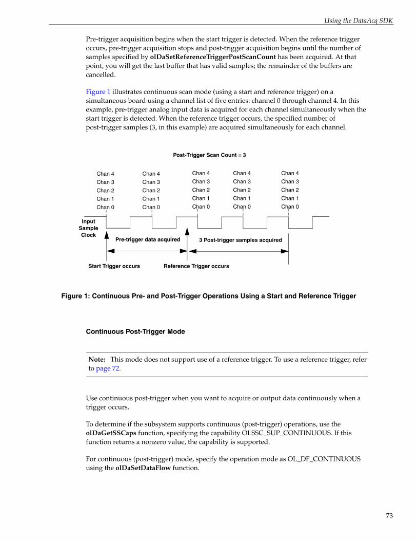
Using the DataAcq SDK
Pre-trigger acquisition begins when the start trigger is detected. When the reference trigger occurs, pre-trigger acquisition stops and post-trigger acquisition begins until the number of samples specified by olDaSetReferenceTriggerPostScanCount has been acquired. At that point, you will get the last buffer that has valid samples; the remainder of the buffers are cancelled.
Figure 1 illustrates continuous scan mode (using a start and reference trigger) on a simultaneous board using a channel list of five entries: channel 0 through channel 4. In this example, pre-trigger analog input data is acquired for each channel simultaneously when the start trigger is detected. When the reference trigger occurs, the specified number of post-trigger samples (3, in this example) are acquired simultaneously for each channel.
Figure 1: Continuous Pre- and Post-Trigger Operations Using a Start and Reference Trigger
Continuous Post-Trigger Mode
Note: This mode does not support use of a reference trigger. To use a reference trigger, refer to page 72.
Use continuous post-trigger when you want to acquire or output data continuously when a trigger occurs.
To determine if the subsystem supports continuous (post-trigger) operations, use the olDaGetSSCaps function, specifying the capability OLSSC_SUP_CONTINUOUS. If this function returns a nonzero value, the capability is supported.
For continuous (post-trigger) mode, specify the operation mode as OL_DF_CONTINUOUS using the olDaSetDataFlow function.
Chan 0
Chan 1
Chan 2
Input Sample Clock
Chan 3
Chan 4
Chan 0
Chan 1
Chan 2
Chan 3
Chan 4
Chan 0
Chan 1
Chan 2
Chan 3
Chan 4
Chan 0
Chan 1
Chan 2
Chan 3
Chan 4
Start Trigger occurs Reference Trigger occurs
3 Post-trigger samples acquiredPre-trigger data acquired
Chan 0
Chan 1
Chan 2
Chan 3
Chan 4
Post-Trigger Scan Count = 3
73

Chapter 3
74
Use the olDaSetTrigger function to specify the trigger source that starts the operation. Refer to page 81 for more information on supported trigger sources.
When the post-trigger event is detected, the device cycles through the channel list, acquiring and/or outputting the value for each entry in the channel list; this process is defined as a scan. The device then wraps to the start of the channel list and repeats the process continuously until either the allocated buffers are filled or you stop the operation. Refer to page 52 for more information on channel lists; refer to page 86 for more information on buffers.
Figure 2 illustrates continuous post-trigger mode using a channel list of three entries: channel 0, channel 1, and channel 2. In this example, post-trigger analog input data is acquired on each clock pulse of the A/D sample clock; refer to page 79 for more information on clock sources. The device wraps to the beginning of the channel list and repeats continuously.
Figure 2: Continuous Post-Trigger Mode
Continuous Pre-Trigger Mode (Legacy Devices)
Note: This mode does not support use of a reference trigger. To use a reference trigger, refer to page 72.
Some older, legacy, devices support pre-trigger mode. Use continuous pre-trigger mode when you want to acquire data before a specific external event occurs.
To determine if the subsystem supports continuous pre-trigger mode, use the olDaGetSSCaps function, specifying the OLSSC_SUP_CONTINUOUS_PRETRIG capability. If this function returns a nonzero value, the capability is supported.
Specify the operation mode as OL_DF_CONTINUOUS_PRETRIG using the olDaSetDataFlow function.
Pre-trigger acquisition starts when the device detects the pre-trigger source and stops when the device detects an external post-trigger source, indicating that the first post-trigger sample was acquired (this sample is ignored).
Post-trigger event occurs
Chan 0Chan 1
Chan 2 Chan 0Chan 1
Chan 2 Chan 0Chan 1
Chan 2 Chan 0Chan 1
Chan 2
A/D Sample Clock
Post-trigger data acquired continuously

Using the DataAcq SDK
Use the olDaSetPretriggerSource function to specify the trigger source that starts the pre-trigger operation (generally this is a software trigger). Specify the post-trigger source that stops the operation using olDaSetTrigger. Refer to page 81 and to your device/driver documentation for supported pre-trigger and post-trigger sources.
Figure 3 illustrates continuous pre-trigger mode using a channel list of three entries: channel 0, channel 1, and channel 2. In this example, pre-trigger analog input data is acquired on each clock pulse of the A/D sample clock; refer to page 79 for more information on clock sources. The device wraps to the beginning of the channel list and the acquisition repeats continuously until the post-trigger event occurs. When the post-trigger event occurs, acquisition stops.
Figure 3: Continuous Pre-Trigger Mode
Continuous About-Trigger Mode (Legacy Devices)
Note: This mode does not support use of a reference trigger. To use a reference trigger, refer to page 72.
Some older, legacy, devices support about-trigger mode. Use continuous about-trigger mode when you want to acquire data both before and after a specific external event occurs. This operation is equivalent to doing both a pre-trigger and a post-trigger acquisition.
To determine if the subsystem supports continuous about-trigger mode, use the olDaGetSSCaps function, specifying the OLSSC_SUP_CONTINUOUS_ABOUTTRIG capability. If this function returns a nonzero value, the capability is supported.
Specify the operation mode as OL_DF_CONTINUOUS_ABOUTTRIG using the olDaSetDataFlow function.
The about-trigger acquisition starts when the device detects the pre-trigger source. When it detects an external post-trigger source, the device stops acquiring pre-trigger data and starts acquiring post-trigger data.
Use the olDaSetPretriggerSource function to specify the pre-trigger source that starts the pre-trigger operation (this is generally a software trigger) and olDaSetTrigger to specify the trigger source that stops the pre-trigger acquisition and starts the post-trigger acquisition.
Pre-trigger event occurs
Chan 0Chan 1
Chan 2 Chan 0Chan 1
Chan 2
A/D Sample Clock
Post-trigger event occurs
Chan 0
Pre-trigger data acquiredAcquisition stops
75

Chapter 3
76
Refer to page 81 and to your device/driver documentation for supported pre-trigger and post-trigger sources.
The about-trigger operation stops when the specified number of post-trigger samples has been acquired or when you stop the operation.
Figure 4 illustrates continuous about-trigger mode using a channel list of three entries: channel 0, channel 1, and channel 2. In this example, pre-trigger analog input data is acquired on each clock pulse of the A/D sample clock. The device wraps to the beginning of the channel list and the acquisition repeats continuously until the post-trigger event occurs. When the post-trigger event occurs, post-trigger acquisition begins on each clock pulse of the A/D sample clock; refer to page 79 for more information on clock sources. The device wraps to the beginning of the channel list and acquires post-trigger data continuously.
Figure 4: Continuous About-Trigger Mode
Triggered Scan Mode
In triggered scan mode, the device scans the entries in a channel-gain list a specified number of times when it detects the specified trigger source, acquiring the data for each entry that is scanned.
To determine if the subsystem supports triggered scan mode, use the olDaGetSSCaps function, specifying the OLSSC_SUP_TRIGSCAN capability. If this function returns a nonzero value, the capability is supported. Note that you cannot use triggered scan mode with single-value operations.
To enable (or disable) triggered scan mode, use the olDaSetTriggeredScanUsage function.
To determine the maximum number of times that the device can scan the channel-gain list per trigger, use the olDaGetSSCaps function, specifying the OLSSC_MAXMULTISCAN capability.
Use the olDaSetMultiscanCount function to specify the number of times to scan the channel-gain list per trigger.
Pre-trigger event occurs
Chan 0Chan 1
Chan 0
. . .
A/D Sample Clock
Post-trigger event occurs
Pre-trigger data acquired Post-trigger data acquired
Chan 1
Chan 0Chan 1
Chan 0
Chan 1
Chan 0Chan 1
Chan 0
Chan 1

Using the DataAcq SDK
The DataAcq SDK defines the following retrigger modes for a triggered scan; these retrigger modes are described in the following subsections:
• Scan-per-trigger
• Internal retrigger
• Retrigger extra
Note: If your device driver supports it, retrigger extra is the preferred triggered scan mode.
Scan-Per-Trigger Mode
Use scan-per-trigger mode if you want to accurately control the period between conversions of individual channels and retrigger the scan based on an internal or external event. In this mode, the retrigger source is the same as the initial trigger source.
To determine if the subsystem supports scan-per-trigger mode, use the olDaGetSSCaps function, specifying the OLSS_SUP_RETRIGGER_SCAN_PER_TRIGGER capability. If this function returns a nonzero value, the capability is supported.
Specify the retrigger mode as scan-per-trigger using the olDaSetRetriggerMode function.
When it detects an initial trigger (post-trigger mode only), the device scans the channel-gain list a specified number of times (determined by the olDaSetMultiscanCount function), then stops. When the external retrigger occurs, the process repeats.
The conversion rate of each channel in the scan is determined by the frequency of the A/D sample clock; refer to page 79 for more information on clock sources. The conversion rate of each scan is determined by the period between retriggers; therefore, it cannot be accurately controlled. The device ignores external triggers that occur while it is acquiring data. Only retrigger events that occur when the device is waiting for a trigger are detected and acted on. Some devices may generate an OLDA_WM_TRIGGER_ERROR message.
Internal Retrigger Mode
Use internal retrigger mode if you want to accurately control both the period between conversions of individual channels in a scan and the period between each scan.
To determine if the subsystem supports internal retrigger mode, use the olDaGetSSCaps function, specifying the OLSS_SUP_RETRIGGER_INTERNAL capability. If this function returns a nonzero value, the capability is supported.
Specify the retrigger mode as internal using the olDaSetRetriggerMode function.
The conversion rate of each channel in the scan is determined by the frequency of the A/D sample clock; refer to page 79 for more information on clock sources. The conversion rate between scans is determined by the frequency of the internal retrigger clock on the device. You specify the frequency on the internal retrigger clock using the olDaSetRetriggerFrequency function.
77

Chapter 3
78
When it detects an initial trigger (pre-trigger source or post-trigger source), the device scans the channel-gain list a specified number of times (determined by the olDaSetMultiscanCount function), then stops. When the internal retrigger occurs, determined by the frequency of the internal retrigger clock, the process repeats.
We recommend that you set the retrigger frequency as follows:
Min. Retrigger = # of CGL entries x # of CGLs per trigger + 2 μsPeriod A/D sample clock frequency
Max. Retrigger = 1 Frequency Min. Retrigger Period
For example, if you are using 512 channels in the channel-gain list (CGL), scanning the channel-gain list 256 times every trigger or retrigger, and using an A/D sample clock with a frequency of 1 MHz, set the maximum retrigger frequency to 7.62 Hz, since
7.62 Hz = 1_______( 512 * 256) +2 μs
1 MHz
Retrigger Extra Mode
Use retrigger extra mode if you want to accurately control the period between conversions of individual channels and retrigger the scan on a specified retrigger source; the retrigger source can be any of the supported trigger sources.
To determine if the subsystem supports retrigger extra mode, use the olDaGetSSCaps function, specifying the OLSSC_SUP_RETRIGGER_EXTRA capability. If this function returns a nonzero value, the capability is supported.
Specify the retrigger mode as retrigger extra using the olDaSetRetriggerMode function.
Use the olDaSetRetrigger function to specify the retrigger source. Refer to page 81 and to your device/device driver documentation for supported retrigger sources.
The conversion rate of each channel in the scan is determined by the frequency of the A/D sample clock; refer to page 79 for more information on clock sources. The conversion rate of each scan is determined by the period between retriggers.
If you are using an internal retrigger, specify the period between retriggers using olDaSetRetriggerFrequency (see page 77). If you are using an external retrigger, the period between retriggers cannot be accurately controlled. The device ignores external triggers that occur while it is acquiring data. Only retrigger events that occur when the device is waiting for a trigger are detected and acted on. Some devices may generate an OLDA_WM_TRIGGER_ERROR message.

Using the DataAcq SDK
Interrupts
Some devices can generate an interrupt when an event occurs, such as when a digital input line changes state (also known as interrupt-on-change). Interrupts are useful when you want to monitor critical signals or when you want to signal the host computer to transfer data to or from the device. You enable interrupts when you configure the driver for the device using the Open Layers Control Panel applet; refer to your device documentation for details.
To determine if your subsystem supports interrupts, use the olDaGetSSCaps function, specifying the capability OLSSC_SUP_INTERRUPT. If this function returns a nonzero value, the capability is supported.
To monitor interrupt-on-change events on a digital input port, use software to set up the subsystem for a continuous digital input operation and start the operation; refer to page 134 for more information.
Note: Single-value operations do not support interrupt-on-change.
An event done message (OLDA_WM_EVENT_DONE) is generated whenever an interrupt-on-change event is detected.
Use the olDaSetWndHandle or olDaSetNotificationProcedure function to handle event done messages; you can read the IParam parameter of these functions to determine which digital line(s) changed state.
Note: For Data Translation PCI boards that support interrupt-on-change, the low word of lParam contains the DIO lines (bits) that caused the event and the high word of lParam contains the status of the digital input port when the interrupt occurred.
For Data Translation USB modules that support interrupt-on-change, the meaning of lParam depends on the module you are using.
Refer to your device documentation for more information.
Clock Sources
The DataAcq SDK defines internal, external, and extra clock sources, described in the following subsections. Note that you cannot specify a clock source for single-value operations.
Note: Some subsystems allow you to read or update multiple channels on a single clock pulse. You can determine whether multiple channels are read or updated on a single clock pulse by using the query OLSSC_SUP_SIMULTANEOUS_CLOCKING.
79

Chapter 3
80
Internal Clock Source
The internal clock is the clock source on the device that paces data acquisition or output for each entry in the channel-gain list.
To determine if the subsystem supports an internal clock, use the olDaGetSSCaps function, specifying the OLSSC_SUP_INTCLOCK capability. If this function returns a nonzero value, the capability is supported.
Specify the clock source as internal using the olDaSetClockSource function. Then, use the olDaSetClockFrequency function to specify the frequency at which to pace the operation.
To determine the maximum frequency that the subsystem supports, use the olDaGetSSCapsEx function, specifying the OLSSCE_MAXTHROUGHPUT capability. To determine the minimum frequency that the subsystem supports, use the olDaGetSSCapsEx function, specifying the OLSSCE_MINTHROUGHPUT capability.
Note: According to sampling theory (Nyquist Theorem), you should specify a frequency for an A/D signal that is at least twice as fast as the input’s highest frequency component. For example, to accurately sample a 20 kHz signal, specify a sampling frequency of at least 40 kHz. Doing so avoids an error condition called aliasing, in which high frequency input components erroneously appear as lower frequencies after sampling.
External Clock Source
The external clock is a clock source attached to the device that paces data acquisition or output for each entry in the channel-gain list. This clock source is useful when you want to pace at rates not available with the internal clock or if you want to pace at uneven intervals.
To determine if the subsystem supports an external clock, use the olDaGetSSCaps function, specifying the OLSSC_SUP_EXTCLOCK capability. If this function returns a nonzero value, the capability is supported.
Specify the clock source as external using the olDaSetClockSource function. Then, use the olDaSetExternalClockDivider to specify the clock divider used to determine the frequency at which to pace the operation; the clock input source divided by the clock divider determines the frequency of the clock signal.
To determine the maximum clock divider that the subsystem supports, use the olDaGetSSCapsEx function, specifying the OLSSCE_MAXCLOCKDIVIDER capability. To determine the minimum clock divider that the subsystem supports, use the olDaGetSSCapsEx function, specifying the OLSSCE_MINCLOCKDIVIDER capability.
Using the DataAcq SDK
Extra Clock Source
Your device driver may define extra clock sources that you can use to pace acquisition or output operations.
To determine how many extra clock sources are supported by your subsystem, use the olDaGetSSCaps function, specifying the OLSSC_NUMEXTRACLOCKS capability. Refer to your device/driver documentation for a description of the extra clock sources.
The extra clock sources may be internal or external. Refer to the previous sections for information on how to specify internal and external clocks and their frequencies or clock dividers.
Trigger Source
The DataAcq SDK defines the following trigger sources:
• Software (internal) trigger
• External digital (TTL) trigger
• External analog threshold (positive) trigger
• External analog threshold (negative) trigger
• Analog event trigger
• Digital event trigger
• Timer event trigger
• Extra trigger
For devices that support a start trigger and reference trigger for performing continuous pre-and post-trigger analog input operations, specify the start trigger type using the olDaSetTrigger function, and specify the reference trigger type using the olDaSetReferenceTrigger function.
For devices that support continuous post-trigger and about-trigger operations without using a reference trigger, specify the post-trigger source using the olDaSetTrigger function; refer to page 73 for more information on post-trigger operations and page 75 for more information on about-trigger operations.
For devices that support a pre-trigger source without using a reference trigger, use the olDaSetPretriggerSource function; see page 74 for more information. To specify a retrigger source, use the olDaSetRetrigger function; see page 78 for more information.
The following subsections describe these trigger sources. Note that you cannot specify a trigger source for single-value operations.
81

Chapter 3
82
Software (Internal) Trigger Source
A software trigger occurs when you start the operation; internally, the computer writes to the device to begin the operation.
To determine if the subsystem supports a software trigger for a start trigger, use the olDaGetSSCaps function, specifying the capability OLSSC_SUP_SOFTTRIG. If this function returns a nonzero value, the capability is supported.
External Digital (TTL) Trigger Source
An external digital trigger is a digital (TTL) signal attached to the device.
To determine if the subsystem supports an external digital trigger for a start trigger, use the olDaGetSSCaps function, specifying the capability OLSSC_SUP_EXTERNTRIG. If this function returns a nonzero value, the capability is supported.
To determine if the subsystem supports a positive external digital trigger for a reference trigger, use the olDaGetSSCaps function, specifying the capability OLSSC_SUP_EXTERNTTLPOS_REFERENCE_TRIG. If this function returns a nonzero value, the capability is supported.
To determine if the subsystem supports a negative external digital trigger for a reference trigger, use the olDaGetSSCaps function, specifying the capability OLSSC_SUP_EXTERNTTLNEG_REFERENCE_TRIG. If this function returns a nonzero value, the capability is supported.
To determine if the subsystem supports a positive, external digital trigger for a single-value operation, use the olDaGetSSCaps function, specifying the capability OLSSC_SUP_SV_POS_EXTERN_TTLTRIG. If this function returns a nonzero value, the capability is supported.
To determine if the subsystem supports a negative, external digital trigger for a single-value operation, use the olDaGetSSCaps function, specifying the capability OLSSC_SUP_SV_NEG_EXTERN_TTLTRIG. If this function returns a nonzero value, the capability is supported.
External Analog Threshold (Positive) Trigger Source
An external analog threshold (positive) trigger is generally either an analog signal from an analog input channel or an external analog signal attached to the device. An analog trigger occurs when the device detects a transition from a negative to positive value that crosses a threshold value. The threshold level is generally set using a D/A subsystem on the device.
To determine if the subsystem supports analog threshold triggering (positive polarity) for a start trigger, use the olDaGetSSCaps function, specifying the capability OLSSC_SUP_THRESHTRIGPOS. If this function returns a nonzero value, the capability is supported.
To determine if the subsystem supports analog threshold triggering (positive polarity) for a reference trigger, use the olDaGetSSCaps function, specifying the capability OLSSC_SUP_THRESHPOS_REFERENCE_TRIG. If this function returns a nonzero value, the capability is supported.

Using the DataAcq SDK
To list the actual channel numbers that support a threshold channel, use the olDaEnumSSCaps function, specifying the capability OL_ENUM_THRESHOLD_START_TRIGGER_CHANNELS for the start trigger or OL_ENUM_THRESHOLD_REFERENCE_TRIGGER_CHANNELS for the reference trigger.
To set the channel that you want to use for the threshold trigger for the start trigger, use the olDaSetTriggerThresholdChannel function. To set the channel that you want to use for the threshold trigger for the reference trigger, use the olDaSetReferenceTriggerThresholdChannel function. By default, channel 0 is used for the threshold channel.
To return the channel that is currently set for the start threshold trigger, use the olDaGetTriggerThresholdChannel function. To return the channel that is currently set for the stop threshold trigger, use the olDaGetReferenceTriggerThresholdChannel function.
On some devices, the threshold level is set using an analog output subsystem on the device. On other devices, you set the threshold level for the start trigger using the olDaSetTriggerThresholdLevel function, and for the reference trigger using the olDaSetReferenceTriggerThresholdLevel function. By default, the trigger threshold value is in voltage unless specified otherwise for the device; see the user’s manual for your device for valid threshold value settings.
Note: The threshold level set by the olDaSetTriggerThresholdLevel or olDaSetReferenceTriggerThresholdLevel function depends on the voltage range and the gain of the subsystem. For example, if the voltage range of the analog input subsystem is ±10 V, and the specified gain is 1, specify a threshold voltage level within ±10 V. Likewise, if the voltage range of the analog input subsystem is ±10 V, and the specified gain is 10, specify a threshold voltage level within ±1 V. Refer to your device documentation for details on how to specify the threshold value for your device.
To return the currently set threshold level for the start trigger, use the olDaGetTriggerThresholdLevel function. To return the currently set threshold level for the reference trigger, use the olDaGetReferenceTriggerThresholdLevel function.
External Analog Threshold (Negative) Trigger Source
An external analog threshold (negative) trigger is generally either an analog signal from an analog input channel or an external analog signal attached to the device. An analog trigger event occurs when the device detects a transition from a positive to negative value that crosses a threshold value. The threshold level is generally set using a D/A subsystem on the device.
To determine if the subsystem supports analog threshold triggering (negative polarity) for a start trigger, use the olDaGetSSCaps function, specifying the capability OLSSC_SUP_THRESHTRIGNEG. If this function returns a nonzero value, the capability is supported.
83

Chapter 3
84
To determine if the subsystem supports analog threshold triggering (negative polarity) for a reference trigger, use the olDaGetSSCaps function, specifying the capability OLSSC_SUP_THRESHNEG_REFERENCE_TRIG. If this function returns a nonzero value, the capability is supported.
To list the actual channel numbers that support a threshold channel, use the olDaEnumSSCaps function, specifying the capability OL_ENUM_THRESHOLD_START_TRIGGER_CHANNELS for the start trigger or OL_ENUM_THRESHOLD_REFERENCE_TRIGGER_CHANNELS for the reference trigger.
To set the channel that you want to use for the threshold trigger for the start trigger, use the olDaSetTriggerThresholdChannel function. To set the channel that you want to use for the threshold trigger for the reference trigger, use the olDaSetReferenceTriggerThresholdChannel function. By default, channel 0 is used for the threshold channel.
To return the channel that is currently set for the start threshold trigger, use the olDaGetTriggerThresholdChannel function. To return the channel that is currently set for the stop threshold trigger, use the olDaGetReferenceTriggerThresholdChannel function.
On some devices, the threshold level is set using an analog output subsystem on the device. On other devices, you set the threshold level for the start trigger using the olDaSetTriggerThresholdLevel function, and for the reference trigger using the olDaSetReferenceTriggerThresholdLevel function. By default, the trigger threshold value is in voltage unless specified otherwise for the device; see the user’s manual for your device for valid threshold value settings.
Note: The threshold level set by the olDaSetTriggerThresholdLevel or olDaSetReferenceTriggerThresholdLevel function depends on the voltage range and gain of the subsystem. For example, if the voltage range of the analog input subsystem is ±10 V, and the specified gain is 1, specify a threshold voltage level within ±10 V. Likewise, if the voltage range of the analog input subsystem is ±10 V, and the specified gain is 10, specify a threshold voltage level within ±1 V. Refer to your device documentation for details on how to specify the threshold value for your device.
To return the currently set threshold level for the start trigger, use the olDaGetTriggerThresholdLevel function. To return the currently set threshold level for the reference trigger, use the olDaGetReferenceTriggerThresholdLevel function.
Sync Bus Trigger Source
For devices that support connecting multiple devices together in a master/slave relationship using Sync Bus (RJ45) connectors, the slave device may support the ability to configure a Sync Bus trigger source as the reference trigger.
To determine if the subsystem supports a Sync Bus trigger source as the reference trigger, use the olDaGetSSCaps function, specifying the capability OLSSC_SUP_SYNCBUS_REFERENCE_TRIG. If this function returns a nonzero value, the capability is supported.

Using the DataAcq SDK
Use the Sync Bus trigger source as the reference trigger if you want the slave device to receive a Sync Bus trigger from one of the other devices to stop pre-trigger acquisition and start post-trigger acquisition.
If you want to set the slave module to receive a Sync Bus trigger as the start trigger source, set the synchronization mode of the device to Slave using the olDaSetSyncMode function, described on page 86; the Sync Bus trigger is used by the slave module as the start trigger source by default.
Analog Event Trigger Source
For this trigger source, a trigger is generated when an analog event occurs. To determine if the subsystem supports an analog event trigger, use the olDaGetSSCaps function, specifying the capability OLSSC_SUP_ANALOGEVENTTRIG. If this function returns a nonzero value, the capability is supported.
Digital Event Trigger Source
For this trigger source, a trigger is generated when a digital event occurs. To determine if the subsystem supports a digital event trigger, use the olDaGetSSCaps function, specifying the capability OLSSC_SUP_DIGITALEVENTTRIG. If this function returns a nonzero value, the capability is supported.
Timer Event Trigger Source
For this trigger source, a trigger is generated when a counter/timer event occurs. To determine if the subsystem supports a timer event trigger, use the olDaGetSSCaps function, specifying the capability OLSSC_SUP_TIMEREVENTTRIG. If this function returns a nonzero value, the capability is supported.
Extra Trigger Source
Extra trigger sources may be defined by your device driver. To determine how many extra triggers are supported by the subsystem, use the olDaGetSSCaps function, specifying the capability OLSSC_NUMEXTRATRIGGERS. Refer to your device/driver documentation for a description of these triggers.
The extra trigger sources may be internal or external. Refer to the previous sections for information on how to specify internal and external triggers.
Post-Trigger Scan Count
On devices that support a reference trigger for performing continuous pre- and post-trigger analog input operations, you can specify how many samples to acquire after the reference trigger occurs using the olDaSetReferenceTriggerPostTriggerScanCount function.
To determine if your device supports the ability to specify the number of post-trigger samples to acquire, use the use the olDaGetSSCaps function, specifying the capability OLSSC_SUP_POST_REFERENCE_TRIG_SCANCOUNT.
85

Chapter 3
86
To return the currently set number of samples to acquire after the reference trigger, use the olDaGetReferenceTriggerPostTriggerScanCount function.
Synchronization Mode
Some devices support one or more synchronization connectors (such as an LVDS RJ45 or Sync Bus connector) that allows you to synchronize operations on multiple devices. In this configuration, the subsystem on one device is configured as the master and the subsystem on the other device is configured as a slave. When the specified subystem of the master module is triggered, the subsystem on both the master device and the slave device start operating at the same time.
To determine if your subsystem supports the ability to program the synchronization mode, use the olDaGetSSCaps function, specifying the OLSSC_SUP_SYNCHRONIZATION capability.
If the subsystem supports programmable synchronization modes, use the olDaSetSyncMode function to set the synchronization mode to one of the following values:
• OL_SYNC_MODE_MASTER – Sets the subsystem as a master; the synchronization connector on the device is configured to output a synchronization signal.
• OL_SYNC_MODE_SLAVE – Sets the subsystem as a slave; the synchronization connector on the device is configured to accept a synchronization signal as an input.
• OL_SYNC_MODE_NONE – The subsystem is configured to ignore the synchronization circuit.
Refer to your hardware documentation to determine how synchronizing multiple devices works on for your device.
Buffers
The buffering capability usually applies to A/D and D/A subsystems only. Note that you cannot use a buffer with single-value operations.
A data buffer is a memory location that you allocate in host memory. This memory location is used to store data for continuous input and output operations.
To determine if the subsystem supports buffers, use the olDaGetSSCaps function, specifying the capability OLSSC_SUP_BUFFERING. If this function returns a nonzero value, the capability is supported.
Buffers are stored on one of three queues: the ready queue, the inprocess queue, or the done queue. These queues are described in more detail in the following subsections.
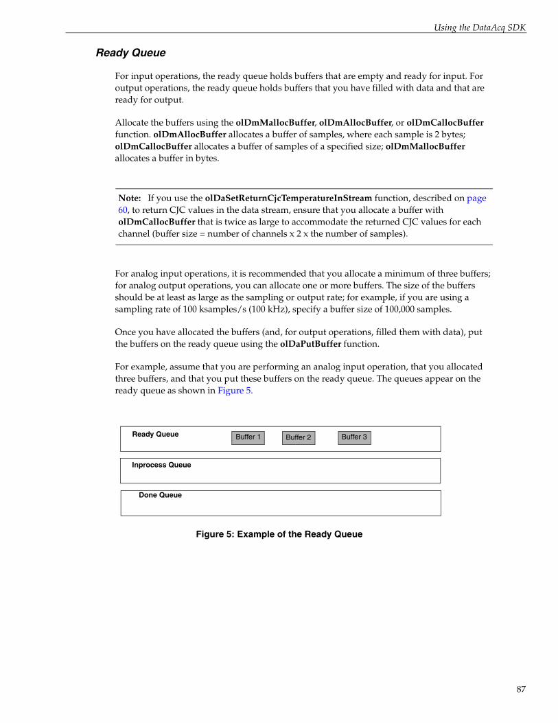
Using the DataAcq SDK
Ready Queue
For input operations, the ready queue holds buffers that are empty and ready for input. For output operations, the ready queue holds buffers that you have filled with data and that are ready for output.
Allocate the buffers using the olDmMallocBuffer, olDmAllocBuffer, or olDmCallocBuffer function. olDmAllocBuffer allocates a buffer of samples, where each sample is 2 bytes; olDmCallocBuffer allocates a buffer of samples of a specified size; olDmMallocBuffer allocates a buffer in bytes.
Note: If you use the olDaSetReturnCjcTemperatureInStream function, described on page 60, to return CJC values in the data stream, ensure that you allocate a buffer with olDmCallocBuffer that is twice as large to accommodate the returned CJC values for each channel (buffer size = number of channels x 2 x the number of samples).
For analog input operations, it is recommended that you allocate a minimum of three buffers; for analog output operations, you can allocate one or more buffers. The size of the buffers should be at least as large as the sampling or output rate; for example, if you are using a sampling rate of 100 ksamples/s (100 kHz), specify a buffer size of 100,000 samples.
Once you have allocated the buffers (and, for output operations, filled them with data), put the buffers on the ready queue using the olDaPutBuffer function.
For example, assume that you are performing an analog input operation, that you allocated three buffers, and that you put these buffers on the ready queue. The queues appear on the ready queue as shown in Figure 5.
Figure 5: Example of the Ready Queue
Ready Queue
Inprocess Queue
Done Queue
Buffer 1 Buffer 2 Buffer 3
87

Chapter 3
88
Inprocess Queue
When you start a continuous (post-trigger, pre-trigger, or about-trigger) operation, the data acquisition device takes the first available buffer from the ready queue and places it on the inprocess queue.
The inprocess queue holds the buffer that the specified data acquisition device is currently filling (for input operations) or outputting (for output operations). The buffer is filled or emptied at the specified clock rate.
Continuing with the previous example, when you start the analog input operation, the driver takes the first available buffer (Buffer 1, in this case), puts it on the inprocess queue, and starts filling it with data. The queues appear as shown in Figure 6.
Figure 6: Example of the Inprocess Queue
If required, you can use the olDaFlushFromBufferInprocess function to transfer data from a partially-filled buffer on an inprocess queue to a buffer you create (if this capability is supported). Typically, you would use this function when your data acquisition operation is running slowly.
To determine if the subsystem supports transferring data from a buffer on the inprocess queue, use the olDaGetSSCaps function, specifying the OLSSC_SUP_INPROCESSFLUSH capability. If this function returns a nonzero value, this capability is supported.
Note: Some devices transfer data to the host in segments instead of one sample at a time. For example, data from the DT3010 device is transferred to the host in 64 byte segments; the number of valid samples is always a multiple of 64 depending on the number of samples transferred to the host when olDaFlushFromBufferInprocess was called. It is up to your application to take this into account when flushing an inprocess buffer. Refer to your device documentation for more information.
Ready Queue
Inprocess Queue
Done Queue
Buffer 1
Buffer 2 Buffer 3

Using the DataAcq SDK
Done Queue
Once the data acquisition device has filled the buffer (for input operations) or emptied the buffer (for output operations), the buffer is moved from the inprocess queue to the done queue. Then, either the OLDA_WM_BUFFER_DONE message is generated when the buffer contains post-trigger data, or in the case of pre-trigger and about-trigger acquisitions, an OLDA_WM_PRETRIGGER_BUFFER_DONE message is generated when the buffer contains pre-trigger data.
Note: For analog input operations that use a reference trigger whose trigger type is something other than software (none), the OLDA_WM_IO_COMPLETE message is generated when the last post-trigger sample is copied into the user buffer. This message includes the total number of samples per channel that were acquired from the time acquisition was started (with the start trigger) to the last post-trigger sample. For example, a value of 100 indicates that a total of 100 samples (samples 0 to 99) were acquired. In some cases, this message is generated well before the OLDA_WM_BUFFER_DONE messages are generated. You can determine when the reference trigger occurred and the number of pre-trigger samples that were acquired by subtracting the post trigger scan count, described on page 85, from the total number of samples that were acquired. Devices that do not support a reference trigger will never receive the OLDA_WM_IO_COMPLETE message for analog input operations.
For pre-trigger acquisitions that do not use a reference trigger, the OLDA_WM_QUEUE_STOPPED message is also generated when the operation completes or you stop a pre-trigger acquisition.
For analog output operations only, the OLDA_WM_IO_COMPLETE message is generated when the last data point has been output from the analog output channel. In some cases, this message is generated well after the data is transferred from the buffer (when the OLDA_WM_BUFFER_DONE and OLDA_WM_QUEUE_DONE messages are generated.
Continuing with the previous example, the queues appear as shown in Figure 7 when you get the first OLDA_WM_BUFFER_DONE message.
Figure 7: Example of the Done Queue
Ready Queue
Inprocess Queue
Done QueueBuffer 1
Buffer 2 Buffer 3
89

Chapter 3
90
Then, the driver moves Buffer 2 from the ready queue to the inprocess queue and starts filling it with data. When Buffer 2 is filled, Buffer 2 is moved to the done queue and another OLDA_WM_BUFFER_DONE message is generated.
The driver then moves Buffer 3 from the ready queue to the inprocess queue and starts filling it with data. When Buffer 3 is filled, Buffer 3 is moved to the done queue and another OLDA_WM_BUFFER_DONE message is generated. Figure 8 shows how the buffers are moved.
Figure 8: How Buffers are Moved to the Done Queue
If you transferred data from an inprocess queue to a new buffer using olDaFlushFromBufferInprocess, the new buffer is put on the done queue for your application to process. When the buffer on the inprocess queue finishes being filled, this buffer is also put on the done queue; the buffer contains only the samples that were not previously transferred.
Buffer and Queue Management
Each time it gets an OLDA_WM_BUFFER_DONE message, your application program should remove the buffers from the done queue using the olDaGetBuffer buffer management function.
Your application program can then process the data in the buffer. For an input operation, you can copy the data from the buffer to an array in your application program using the olDmGetBufferPtr function. For continuously paced analog output operations, you can fill the buffer with new output data using the olDaGetBufferPtr function.
If you want to convert the count value to engineering units, you can use the olDaCodeToVolts function. Similarly, if you want to convert the engineering units to counts, you can use the olDaVoltsToCode function.
For channels that support strain gage inputs, you can convert the value in voltage to a strain value by using the olDaVoltsToStrain function or to a value for a bridge-based sensor using the olDaVoltsToBridgeBasedSensor function.
When you are finished processing the data, you can put the buffer back on the ready queue using the olDaPutBuffer function if you want your operation to continue.
Ready Queue
Inprocess Queue
Done Queue Buffer 1 Buffer 2 Buffer 3

Using the DataAcq SDK
For example, assume that you processed the data from Buffer 1 and put it back on the ready queue. The queues would appear as shown in Figure 9.
Figure 9: Putting Buffers Back on the Ready Queue
When the data acquisition operation is finished, use the olDaFlushBuffers function to transfer any data buffers left on the subsystem’s ready queue to the done queue.
Once you have processed the data in the buffers, remove the buffers from the done queue using the olDaFreeBuffer function.
Buffer Wrap Modes
Most Data Translation data acquisition devices can provide gap-free data, meaning no samples are missed when data is acquired or output. You can acquire gap-free data by manipulating data buffers so that no gaps exist between the last sample of the current buffer and the first sample of the next buffer.
Note: The number of DMA channels, number of buffers, and buffer size are critical to the device’s ability to provide gap-free data. It is also critical that the application process the data in a timely fashion.
If you want to acquire gap-free input data, we recommend that you specify a buffer wrap mode of none using the olDaSetWrapMode buffer management function. When a buffer wrap mode of none is selected, the operation continues indefinitely if you process the buffers and put them back on the ready queue in a timely manner. When no buffers are available on the ready queue, the operation stops, and an OLDA_WM_QUEUE_DONE message is generated.
If you want to continuously reuse the buffers in the queues and you are not concerned with gap-free data, specify multiple buffer wrap mode using olDaSetWrapMode. When multiple wrap mode is selected and no buffers are available on the ready queue, the driver overwrites the data in the current buffer. This process continues indefinitely until you stop it. When it reuses a buffer on the done queue, the driver generates an OLDA_WM_BUFFER_REUSED message.
Ready Queue
Inprocess Queue
Done Queue
Buffer 1
Buffer 2
Buffer 3
91
Chapter 3
92
If you want to output gap-free waveforms from your analog output channels, specify single wrap mode using olDaSetWrapMode. When single wrap mode is specified, a single buffer is used.
If the device has a FIFO and the buffer fits into the FIFO, the buffer is downloaded to the FIFO on the device. The driver (or device) outputs the data starting from the first location in the buffer. When it reaches the end of the buffer, the driver (or device) continues outputting data from the first location of the buffer, and the process continues indefinitely until you stop it. Typically, no messages are posted in this mode until you stop the operation.
Note: If the size of your buffer is less than the FIFO size and you stop the analog output operation, the operation stops after the current buffer and the next buffer have been output.
If you query the subsystem with the OLSSC_SUP_WRPWAVEFORM_ONLY capability and the olDaGetSSCaps function returns a nonzero value, the subsystem supports waveform-based operations using the onboard FIFO only. In this case, the buffer wrap mode must be set to single. In addition, the buffer size must be less than or equal to the FIFO size. You can determine whether the subsystem supports a FIFO using the olDaGetSSCaps function with the capability OLSSC_SUP_FIFO. If this function returns a nonzero value, a FIFO is supported. You can determine the size of the FIFO using the capability OLSSC_FIFO_SIZE_IN_K. This query returns the actual FIFO size in kilobytes.
To determine the buffer wrap modes available for the subsystem, use the olDaGetSSCaps function, specifying the capability OLSSC_SUP_WRPSINGLE (for single wrap mode) or OLSSC_SUP_WRPMULTIPLE (for multiple wrap mode). If this function returns a nonzero value, the capability is supported.

Using the DataAcq SDK
DMA Resources
You cannot use DMA resources for single-value operations.
To determine if gap-free data acquisition is supported, use the olDaGetSSCaps function, specifying OLSSC_SUP_GAPFREE_NODMA (for gap free data using no DMA channels), OLSSC_SUP_GAPFREE_SINGLEDMA (for gap free data using one DMA channel), or OLSSC_SUP_GAPFREE_DUALDMA (for gap free data using two DMA channels). If this function returns a nonzero value, the capability is supported.
To determine how many DMA channels are supported, use the olDaGetSSCaps function, specifying the capability OLSSC_NUMDMACHANS.
Use the olDaSetDmaUsage function to specify the number of DMA channels to use. These channels must also be specified in the driver configuration dialog.
Note: DMA channels are a limited resource and the request may not be honored if the requested number of channels is unavailable. For example, suppose that a device that supports both A/D and D/A subsystems provides hardware for two DMA channels, and that one DMA channel is currently allocated to the A/D subsystem. In this case, a request to the D/A subsystem to use two DMA channels will fail.
93

Chapter 3
94
Counter/Timer Operations The counter/timer subsystem supports general-purpose user counter/timers and may support measure counters and quadrature decoders. Refer to page 123 for more information on measure counters. Refer to page 123 for more information on quadrature decoders. The rest of this section describes the operation of general-purpose counter/timers.
User Counter/Timers
Each user counter/timer channel accepts a clock input signal and gate input signal and outputs a clock output signal (also called a pulse output signal), as shown in Figure 10.
Figure 10: Counter/Timer Channel
Each counter/timer channel corresponds to a counter/timer (C/T) subsystem. To specify the counter to use in software, specify the appropriate C/T subsystem. For example, counter 0 corresponds to C/T subsystem element 0; counter 3 corresponds to C/T subsystem element 3.
The DataAcq SDK defines the following capabilities that you can query and/or configure for user counter/timer operations:
• Counter/timer operation mode
• Clock source
• Gate source
• Pulse output type
• Pulse output duty cycle
The following sections describe these capabilities in more detail.
Counter/Timer Operation Mode
The DataAcq SDK supports the following counter/timer operations:
• Event counting
• Up/down counting
• Frequency measurement
Clock Input SIgnal(internal, external, or internally cascaded)
Counter/Timer
Gate Input Signal(software or external input)
Pulse Output Signal

Using the DataAcq SDK
• Edge-to-edge measurement
• Continuous edge-to-edge measurement
• Rate generation (continuous pulse output)
• One-shot
• Repetitive one-shot
The following subsections describe these counter/timer operations.
Event Counting
Use event counting mode to count events from the counter’s associated clock input source.
To determine if the subsystem supports event counting, use the olDaGetSSCaps function, specifying the capability OLSSC_SUP_CTMODE_COUNT. If this function returns a nonzero value, the capability is supported.
To specify an event counting operation, use the olDaSetCTMode function, specifying the OL_CTMODE_COUNT parameter.
Specify the C/T clock source for the operation. In event counting mode, an external C/T clock source is more useful than the internal C/T clock source; refer to page 112 for more information on specifying the C/T clock source.
Also specify the gate type that enables the operation; refer to page 114 for more information on specifying the gate type.
Start an event counting operation using the olDaStart function. To read the current number of events counted, use the olDaReadEvents function.
To stop the event counting operation, call olDaStop, olDaAbort, or olDaReset; olDaReset function stops the operation and reinitializes the subsystem after stopping it.
Figure 11 shows an example of an event counting operation. In this example the gate type is low level.
95
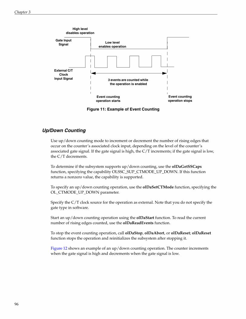
Chapter 3
96
Figure 11: Example of Event Counting
Up/Down Counting
Use up/down counting mode to increment or decrement the number of rising edges that occur on the counter’s associated clock input, depending on the level of the counter’s associated gate signal. If the gate signal is high, the C/T increments; if the gate signal is low, the C/T decrements.
To determine if the subsystem supports up/down counting, use the olDaGetSSCaps function, specifying the capability OLSSC_SUP_CTMODE_UP_DOWN. If this function returns a nonzero value, the capability is supported.
To specify an up/down counting operation, use the olDaSetCTMode function, specifying the OL_CTMODE_UP_DOWN parameter.
Specify the C/T clock source for the operation as external. Note that you do not specify the gate type in software.
Start an up/down counting operation using the olDaStart function. To read the current number of rising edges counted, use the olDaReadEvents function.
To stop the event counting operation, call olDaStop, olDaAbort, or olDaReset; olDaReset function stops the operation and reinitializes the subsystem after stopping it.
Figure 12 shows an example of an up/down counting operation. The counter increments when the gate signal is high and decrements when the gate signal is low.
Gate InputSignal Low level
enables operation
High leveldisables operation
External C/T Clock
Input Signal
Event countingoperation starts
Event countingoperation stops
3 events are counted while the operation is enabled

Using the DataAcq SDK
Figure 12: Example of Up/Down Counting
Frequency Measurement
You can also use event counting mode to measure the frequency of the clock input signal for the counter, since frequency is the number of events divided by a specified duration.
To determine if the subsystem supports event counting (and therefore, frequency measurement), use the olDaGetSSCaps function, specifying the capability OLSSC_SUP_CTMODE_COUNT. If this function returns a nonzero value, the capability is supported.
You can perform a frequency measurement operation in one of two ways: using the Windows timer to specify the duration or using a pulse of a known duration as the gate input signal to a counter/timer configured for event counting mode. The following subsections describe these ways of measuring frequency.
Using the Windows Timer
To perform a frequency measurement operation on a single C/T subsystem using the Windows timer to specify the duration, do the following:
1. Use the olDaSetCTMode function, specifying the OL_CTMODE_COUNT parameter.
2. Specify the input clock source using olDaSetClockSource. In frequency measurement mode, an external C/T clock source is more useful than the internal C/T clock source; refer to page 112 for more information on the external C/T clock source.
3. Use the olDaSetGateType function, specifying the OL_GATE_NONE parameter, to set the gate type to software.
4. Use the olDaMeasureFrequency function to specify the duration of the Windows timer (which has a resolution of 1 ms) and to start the frequency measurement operation.
Gate InputSignal
High-level gate; count increments on rising edges
Low-level gate; count decrements
on rising edges
External C/T Clock
Input Signal
Up/down countingoperation starts
Up/down countingoperation stops
3 rising edges are counted while the gate
is high; count = 0 + 3 = 3
2 rising edges are counted while
the gate is low; count = 3 - 2 = 1
97

Chapter 3
98
Frequency is determined using the following equation:
Frequency = Number of Events Duration of the Windows Timer
When the operation is complete, the OLDA_WM_MEASURE_DONE message is generated. Use the LongtoFreq (lParam) macro, described in the DataAcq SDK online help, to return the measured frequency value.
Figure 13 shows an example of a frequency measurement operation. Three events are counted from the clock input signals during a duration of 300 ms. The frequency is 10 Hz (3/.3).
Figure 13: Example of Frequency Measurement
Using a Pulse of a Known Duration
If you need more accuracy than the Windows timer provides, you can connect a pulse of a known duration to the external gate input of a counter/timer configured for event counting; refer to the device user manual for wiring details.
The following example describes how to use the DataAcq SDK to measure frequency using two C/T subsystems: one that generates a variable-width one-shot pulse as the gate input to a second C/T subsystem configured for event counting mode:
1. Set up one C/T subsystem for one-shot mode as follows:
a. Use the olDaSetCTMode function, specifying the OL_CTMODE_ONESHOT parameter.
b. For this C/T subsystem, specify the clock source (with olDaSetClockSource), the clock frequency (with olDaSetClockFrequency if using an internal clock source, or olDaSetExternalClockDivider if using an external clock source), the gate type (with olDaSetGateType), the type of output pulse (with olDaSetPulseType), and the pulse width (with olDaSetPulseWidth). The pulse width and period are used to determine the time that the gate is active.
c. Configure this C/T subsystem with olDaConfig.
External C/T Clock
Input Signal
frequency measurementstarts
frequency measurement stops
Duration over which thefrequency is measured = 300 ms
3 Events Counted
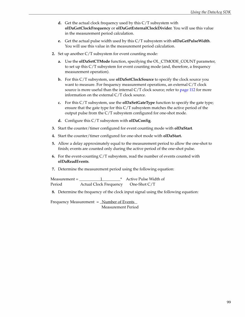
Using the DataAcq SDK
d. Get the actual clock frequency used by this C/T subsystem with olDaGetClockFrequency or olDaGetExternalClockDivider. You will use this value in the measurement period calculation.
e. Get the actual pulse width used by this C/T subsystem with olDaGetPulseWidth. You will use this value in the measurement period calculation.
2. Set up another C/T subsystem for event counting mode:
a. Use the olDaSetCTMode function, specifying the OL_CTMODE_COUNT parameter, to set up this C/T subsystem for event counting mode (and, therefore, a frequency measurement operation).
b. For this C/T subsystem, use olDaSetClockSource to specify the clock source you want to measure. For frequency measurement operations, an external C/T clock source is more useful than the internal C/T clock source; refer to page 112 for more information on the external C/T clock source.
c. For this C/T subsystem, use the olDaSetGateType function to specify the gate type; ensure that the gate type for this C/T subsystem matches the active period of the output pulse from the C/T subsystem configured for one-shot mode.
d. Configure this C/T subsystem with olDaConfig.
3. Start the counter/timer configured for event counting mode with olDaStart.
4. Start the counter/timer configured for one-shot mode with olDaStart.
5. Allow a delay approximately equal to the measurement period to allow the one-shot to finish; events are counted only during the active period of the one-shot pulse.
6. For the event-counting C/T subsystem, read the number of events counted with olDaReadEvents.
7. Determine the measurement period using the following equation:
Measurement = 1 * Active Pulse Width of Period Actual Clock Frequency One-Shot C/T
8. Determine the frequency of the clock input signal using the following equation:
Frequency Measurement = Number of Events Measurement Period
99

Chapter 3
100
Edge-to-Edge Measurement
Use edge-to-edge measurement to measure the time interval between a specified start edge and a specified stop edge. The start edge and the stop edge can occur on the rising edge of the counter’s associated gate input, the falling edge of the counter’s associated gate input, the rising edge of the counter’s associated clock input, or the falling edge of the counter’s associated clock input. When the start edge is detected, the counter starts incrementing, and continues incrementing until the stop edge is detected.
To determine if the subsystem supports edge-to-edge measurement, use the olDaGetSSCaps function, specifying the capability OLSSC_SUP_CTMODE_MEASURE. This function returns a bit value indicating how edge-to-edge measurement mode is supported for the specified device. For example, if edge-to-edge measurements are supported on the gate signal only (using both rising and falling edges), a bit value of 3 is returned. Table 12 lists the possible bit values.
Table 12: Values for OLSCC_SUP_CTMODE_MEASURE
Value Name Description
0x00 − Edge-to-edge measurements are not supported.
0x01 SUP_GATE_RISING_BIT Rising edge of the gate signal is supported for edge-to-edge measurement mode.
0x02 SUP_GATE_FALLING_BIT Falling edge of the gate signal is supported for edge-to-edge measurement mode.
0x04 SUP_CLOCK_RISING_BIT Rising edge of the clock signal is supported for edge-to-edge measurement mode.
0x08 SUP_CLOCK_FALLING_BIT Falling edge of the clock signal is supported for edge-to-edge measurement mode.
0x10 SUP_ADC_CONVERSION_COMPLETE_BIT A/D conversion is complete is supported as an edge type for edge-to-edge measurement mode.
0x20 SUP_TACHOMETER_INPUT_FALLING_BIT Falling edge of the tachometer input signal is supported for edge-to-edge measurement mode.
0x40 SUP_TACHOMETER_INPUT_RISING_BIT Rising edge of the tachometer input signal is supported for edge-to-edge measurement mode.
0x80 SUP_DIGITAL_INPUT_0_FALLING_BIT Falling edge of digital input 0 is supported for edge-to-edge measurement mode.
0x100 SUP_DIGITAL_INPUT_0_RISING_BIT Rising edge of digital input 0 is supported for edge-to-edge measurement mode.
0X200 SUP_DIGITAL_INPUT_1_FALLING_BIT Falling edge of digital input 1 is supported for edge-to-edge measurement mode.
0X400 SUP_DIGITAL_INPUT_1_RISING_BIT Rising edge of digital input 1 is supported for edge-to-edge measurement mode.

Using the DataAcq SDK
To specify an edge-to-edge measurement operation, use the olDaSetCTMode function, specifying the OL_CTMODE_MEASURE parameter.
Specify the C/T clock source for the operation as internal. Specify the start edge with the olDaSetMeasureStartEdge function and the stop edge with olDaSetMeasureStopEdge function. Configure the counter/timer with olDaConfig.
0X800 SUP_DIGITAL_INPUT_2_FALLING_BIT Falling edge of digital input 2 is supported for edge-to-edge measurement mode.
0X1000 SUP_DIGITAL_INPUT_2_RISING_BIT Rising edge of digital input 2 is supported for edge-to-edge measurement mode.
0X2000 SUP_DIGITAL_INPUT_3_FALLING_BIT Falling edge of digital input 3 is supported for edge-to-edge measurement mode.
0X4000 SUP_DIGITAL_INPUT_3_RISING_BIT Rising edge of digital input 3 is supported for edge-to-edge measurement mode.
0X8000 SUP_DIGITAL_INPUT_4_FALLING_BIT Falling edge of digital input 4 is supported for edge-to-edge measurement mode.
0X10000 SUP_DIGITAL_INPUT_4_RISING_BIT Rising edge of digital input 4 is supported for edge-to-edge measurement mode.
0X20000 SUP_DIGITAL_INPUT_5_FALLING_BIT Falling edge of digital input 5 is supported for edge-to-edge measurement mode.
0X40000 SUP_DIGITAL_INPUT_5_RISING_BIT Rising edge of digital input 5 is supported for edge-to-edge measurement mode.
0X80000 SUP_DIGITAL_INPUT_6_FALLING_BIT Falling edge of digital input 6 is supported for edge-to-edge measurement mode.
0X100000 SUP_DIGITAL_INPUT_6_RISING_BIT Rising edge of digital input 6 is supported for edge-to-edge measurement mode.
0X200000 SUP_DIGITAL_INPUT_7_FALLING_BIT Falling edge of digital input 7 is supported for edge-to-edge measurement mode.
0X400000 SUP_DIGITAL_INPUT_7_RISING_BIT Rising edge of digital input 7 is supported for edge-to-edge measurement mode.
0X800000 SUP_CT0_CLOCK_INPUT_FALLING_BIT Falling edge of the clock input signal associated with counter/timer 0 is supported for edge-to-edge measurement mode.
0X1000000 SUP_CT0_CLOCK_INPUT_RISING_BIT Rising edge of the clock input signal associated with counter/timer 0 is supported for edge-to-edge measurement mode.
0X2000000 SUP_CT0_GATE_INPUT_FALLING_BIT Falling edge of the gate input signal associated with counter/timer 0 is supported for edge-to-edge measurement mode.
0X4000000 SUP_CT0_GATE_INPUT_RISING_BIT Rising edge of the gate input signal associated with counter/timer 0 is supported for edge-to-edge measurement mode.
Table 12: Values for OLSCC_SUP_CTMODE_MEASURE
Value Name Description
101

Chapter 3
102
Start an edge-to-edge measurement operation using the olDaStart function. To read the current counter value, use the olDaReadEvents function.
To stop the edge-to-edge measurement operation, call olDaStop, olDaAbort, or olDaReset; olDaReset function stops the operation and reinitializes the subsystem after stopping it.
Figure 14 shows an example of an edge-to-edge measurement operation. The start edge is a rising edge on the gate signal; the stop edge is a falling edge on the gate signal.
Figure 14: Example of Edge-to-Edge Measurement
You can use edge-to-edge measurement to measure the following:
• Pulse width of a signal pulse (the amount of time that a signal pulse is in a high or a low state, or the amount of time between a rising edge and a falling edge or between a falling edge and a rising edge). You can calculate the pulse width as follows:
− Pulse width = Number of counts/Internal C/T Clock Freq
• Period of a signal pulse (the time between two occurrences of the same edge - rising edge to rising edge or falling edge to falling edge). You can calculate the period as follows:
− Period = 1/Frequency
− Period = Number of counts/Internal C/T Clock Freq
• Frequency of a signal pulse (the number of periods per second). You can calculate the frequency as follows:
− Frequency = Internal C/T Clock Freq/Number of Counts
Gate InputSignal
Rising-edge on gate; count starts
Falling-edge on gate; count stop
External C/T Clock
Input Signal
Edge-to-edge measurement operation starts
Edge-to-edge measurement operation stops
3 rising edges are counted between the start edge and
the stop edge
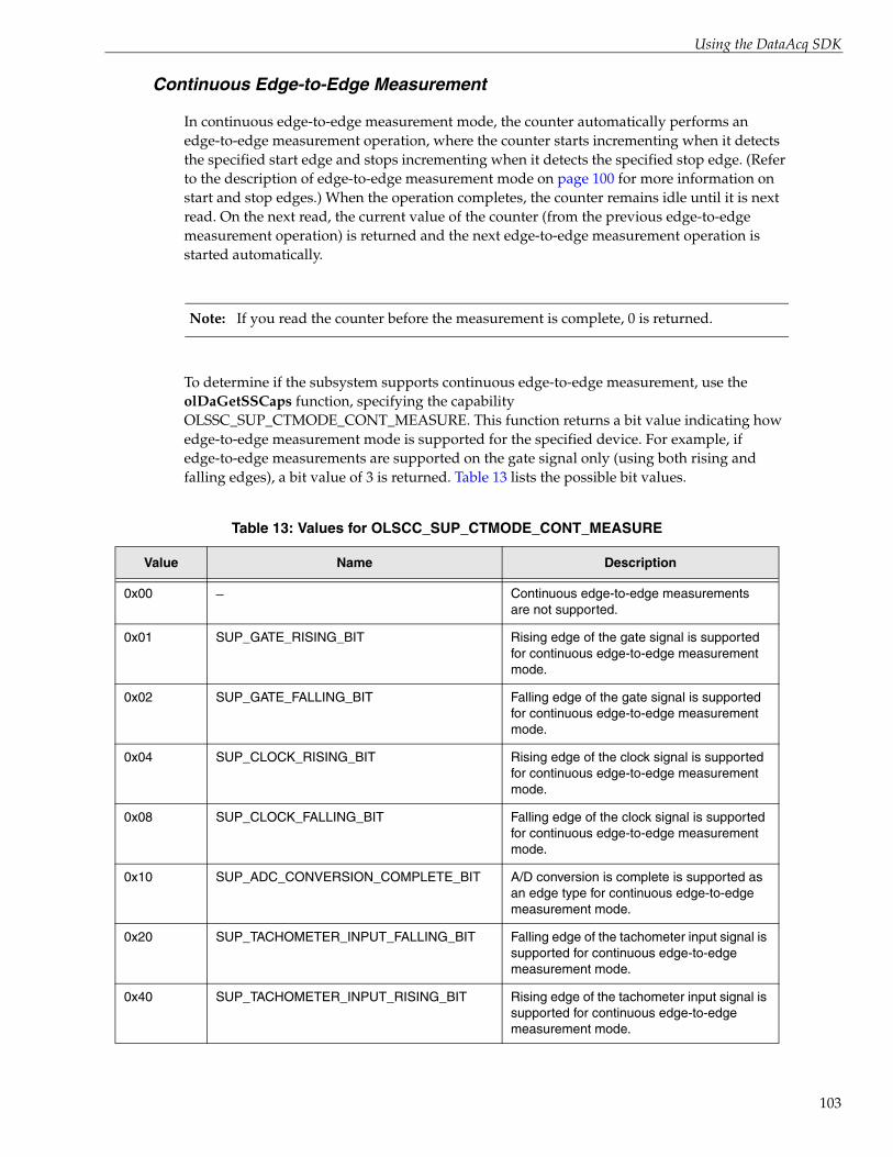
Using the DataAcq SDK
Continuous Edge-to-Edge Measurement
In continuous edge-to-edge measurement mode, the counter automatically performs an edge-to-edge measurement operation, where the counter starts incrementing when it detects the specified start edge and stops incrementing when it detects the specified stop edge. (Refer to the description of edge-to-edge measurement mode on page 100 for more information on start and stop edges.) When the operation completes, the counter remains idle until it is next read. On the next read, the current value of the counter (from the previous edge-to-edge measurement operation) is returned and the next edge-to-edge measurement operation is started automatically.
Note: If you read the counter before the measurement is complete, 0 is returned.
To determine if the subsystem supports continuous edge-to-edge measurement, use the olDaGetSSCaps function, specifying the capability OLSSC_SUP_CTMODE_CONT_MEASURE. This function returns a bit value indicating how edge-to-edge measurement mode is supported for the specified device. For example, if edge-to-edge measurements are supported on the gate signal only (using both rising and falling edges), a bit value of 3 is returned. Table 13 lists the possible bit values.
Table 13: Values for OLSCC_SUP_CTMODE_CONT_MEASURE
Value Name Description
0x00 − Continuous edge-to-edge measurements are not supported.
0x01 SUP_GATE_RISING_BIT Rising edge of the gate signal is supported for continuous edge-to-edge measurement mode.
0x02 SUP_GATE_FALLING_BIT Falling edge of the gate signal is supported for continuous edge-to-edge measurement mode.
0x04 SUP_CLOCK_RISING_BIT Rising edge of the clock signal is supported for continuous edge-to-edge measurement mode.
0x08 SUP_CLOCK_FALLING_BIT Falling edge of the clock signal is supported for continuous edge-to-edge measurement mode.
0x10 SUP_ADC_CONVERSION_COMPLETE_BIT A/D conversion is complete is supported as an edge type for continuous edge-to-edge measurement mode.
0x20 SUP_TACHOMETER_INPUT_FALLING_BIT Falling edge of the tachometer input signal is supported for continuous edge-to-edge measurement mode.
0x40 SUP_TACHOMETER_INPUT_RISING_BIT Rising edge of the tachometer input signal is supported for continuous edge-to-edge measurement mode.
103

Chapter 3
104
0x80 SUP_DIGITAL_INPUT_0_FALLING_BIT Falling edge of digital input 0 is supported for continuous edge-to-edge measurement mode.
0x100 SUP_DIGITAL_INPUT_0_RISING_BIT Rising edge of digital input 0 is supported for continuous edge-to-edge measurement mode.
0X200 SUP_DIGITAL_INPUT_1_FALLING_BIT Falling edge of digital input 1 is supported for continuous edge-to-edge measurement mode.
0X400 SUP_DIGITAL_INPUT_1_RISING_BIT Rising edge of digital input 1 is supported for continuous edge-to-edge measurement mode.
0X800 SUP_DIGITAL_INPUT_2_FALLING_BIT Falling edge of digital input 2 is supported for continuous edge-to-edge measurement mode.
0X1000 SUP_DIGITAL_INPUT_2_RISING_BIT Rising edge of digital input 2 is supported for continuous edge-to-edge measurement mode.
0X2000 SUP_DIGITAL_INPUT_3_FALLING_BIT Falling edge of digital input 3 is supported for continuous edge-to-edge measurement mode.
0X4000 SUP_DIGITAL_INPUT_3_RISING_BIT Rising edge of digital input 3 is supported for continuous edge-to-edge measurement mode.
0X8000 SUP_DIGITAL_INPUT_4_FALLING_BIT Falling edge of digital input 4 is supported for continuous edge-to-edge measurement mode.
0X10000 SUP_DIGITAL_INPUT_4_RISING_BIT Rising edge of digital input 4 is supported for continuous edge-to-edge measurement mode.
0X20000 SUP_DIGITAL_INPUT_5_FALLING_BIT Falling edge of digital input 5 is supported for continuous edge-to-edge measurement mode.
0X40000 SUP_DIGITAL_INPUT_5_RISING_BIT Rising edge of digital input 5 is supported for continuous edge-to-edge measurement mode.
0X80000 SUP_DIGITAL_INPUT_6_FALLING_BIT Falling edge of digital input 6 is supported for continuous edge-to-edge measurement mode.
0X100000 SUP_DIGITAL_INPUT_6_RISING_BIT Rising edge of digital input 6 is supported for continuous edge-to-edge measurement mode.
0X200000 SUP_DIGITAL_INPUT_7_FALLING_BIT Falling edge of digital input 7 is supported for continuous edge-to-edge measurement mode.
Table 13: Values for OLSCC_SUP_CTMODE_CONT_MEASURE
Value Name Description

Using the DataAcq SDK
To specify a continuous edge-to-edge measurement operation, use the olDaSetCTMode function, specifying the OL_CTMODE_CONT_MEASURE parameter.
Specify the C/T clock source for the operation as internal. Specify the start edge with the olDaSetMeasureStartEdge function and the stop edge with olDaSetMeasureStopEdge function.
When you configure the counter/timer with olDaConfig, the continuous edge-to-edge measurement operation starts immediately.
0X400000 SUP_DIGITAL_INPUT_7_RISING_BIT Rising edge of digital input 7 is supported for continuous edge-to-edge measurement mode.
0X800000 SUP_CT0_CLOCK_INPUT_FALLING_BIT Falling edge of the clock input signal associated with counter/timer 0 is supported for continuous edge-to-edge measurement mode.
0X1000000 SUP_CT0_CLOCK_INPUT_RISING_BIT Rising edge of the clock input signal associated with counter/timer 0 is supported for continuous edge-to-edge measurement mode.
0X2000000 SUP_CT0_GATE_INPUT_FALLING_BIT Falling edge of the gate input signal associated with counter/timer 0 is supported for continuous edge-to-edge measurement mode.
0X4000000 SUP_CT0_GATE_INPUT_RISING_BIT Rising edge of the gate input signal associated with counter/timer 0 is supported for continuous edge-to-edge measurement mode.
Table 13: Values for OLSCC_SUP_CTMODE_CONT_MEASURE
Value Name Description
105

Chapter 3
106
To read the current counter value, use the olDaReadEvents function or read the counter/timer channel as part of the analog input channel-gain list, if the device supports this capability. For example, you might see results similar to the following if you read the counter/timer channel as part of the analog input channel list:
You can use a continuous edge-to-edge measurement to measure the following:
• Pulse width of a signal pulse (the amount of time that a signal pulse is in a high or a low state, or the amount of time between a rising edge and a falling edge or between a falling edge and a rising edge). You can calculate the pulse width as follows:
− Pulse width = Number of counts/Internal C/T Clock Freq
• Period of a signal pulse (the time between two occurrences of the same edge - rising edge to rising edge or falling edge to falling edge). You can calculate the period as follows:
− Period = 1/Frequency
− Period = Number of counts/Internal C/T Clock Freq
• Frequency of a signal pulse (the number of periods per second). You can calculate the frequency as follows:
− Frequency = Internal C/T Clock Freq/Number of Counts
To stop a continuous edge-to-edge measurement operation, call olDaStop, olDaAbort, or olDaReset; olDaReset function stops the operation and reinitializes the subsystem after stopping it.
Time A/D Value Counter/Timer ValueStatus of Continuous Edge-to-Edge
Measurement Mode
10 5002 0 Operation started when the C/T subsystem was configured, but is not complete
20 5004 0 Operation not complete
30 5003 0 Operation not complete
40 5002 12373 Operation complete
50 5000 0 Next operation started, but is not complete
60 5002 0 Operation not complete
70 5004 0 Operation not complete
80 5003 12403 Operation complete
90 5002 0 Next operation started, but is not complete

Using the DataAcq SDK
Rate Generation
Use rate generation mode to generate a continuous pulse output signal from the counter; this mode is sometimes referred to as continuous pulse output or pulse train output. You can use this pulse output signal as an external clock to pace analog input, analog output, or other counter/timer operations.
To determine if the subsystem supports rate generation, use the olDaGetSSCaps function, specifying the capability OLSSC_SUP_CTMODE_RATE. If this function returns a nonzero value, the capability is supported.
To specify a rate generation mode, use the olDaSetCTMode function, specifying the OL_CTMODE_RATE parameter.
Specify the C/T clock source for the operation. In rate generation mode, either the internal or external C/T clock input source is appropriate depending on your application; refer to page 112 for information on specifying the C/T clock source.
Specify the frequency of the C/T clock output signal. For an internal C/T, the olDaSetClockFrequency function determines the frequency of the output pulse. For an external C/T clock source, the frequency of the clock input source divided by the clock divider (specified with the olDaSetExternalClockDivider function) determines the frequency of the output pulse.
Specify the polarity of the output pulses (high-to-low transitions or low-to-high transitions) and the duty cycle of the output pulses; refer to page 117 for more information.
Also specify the gate type that enables the operation; refer to page 114 for more information on specifying the gate type.
Start rate generation mode using the olDaStart function. While rate generation mode is enabled, the counter outputs a pulse of the specified type and frequency continuously. As soon as the operation is disabled, the pulse output operation stops.
To stop rate generation if it is in progress, call olDaStop, olDaAbort, or olDaReset; olDaReset stops the operation and reinitializes the subsystem after stopping it.
Figure 15 shows an example of an enabled rate generation operation using an external C/T clock source with an input frequency of 4 kHz, a clock divider of 4, a low-to-high pulse type, and a duty cycle of 50%. (The gate type does not matter for this example.) A 1 kHz square wave is the generated output.
107

Chapter 3
108
Figure 15: Example of Rate Generation Mode with a 50% Duty Cycle
Figure 16 shows the same example using a duty cycle of 75%.
Figure 16: Example of Rate Generation Mode with a 75% Duty Cycle
Figure 17 shows the same example using a duty cycle of 25%.
PulseOutputSignal
External C/T Clock
Input Signal(4 kHz)
50% duty cycle
Continuous PulseOutput Operation Starts
PulseOutputSignal
External C/T Clock
Input Signal(4 kHz)
75% duty cycle
Continuous PulseOutput Operation Starts

Using the DataAcq SDK
Figure 17: Example of Rate Generation Mode with a 25% Duty Cycle
One-Shot
Use one-shot mode to generate a single pulse output signal from the counter when the operation is triggered (determined by the gate input signal). You can use this pulse output signal as an external digital (TTL) trigger to start analog input, analog output, or other operations.
To determine if the subsystem supports one-shot mode, use the olDaGetSSCaps function, specifying the capability OLSSC_SUP_CTMODE_ONESHOT. If this function returns a nonzero value, the capability is supported.
To specify a one-shot operation, use the olDaSetCTMode function, specifying the OL_CTMODE_ONESHOT parameter.
Specify the C/T clock source for the operation. Refer to page 112 for more information on specifying the C/T clock source.
Specify the polarity of the output pulse (high-to-low transition or low-to-high transition) and the duty cycle of the output pulse; refer to page 117 for more information.
Note: In the case of a one-shot operation, set the duty cycle to 100% to output a pulse immediately. Using a duty cycle less then 100% acts as a pulse output delay.
Also specify the gate type that triggers the operation; refer to page 114 for more information.
Configure the operation with the olDaConfig function.
PulseOutputSignal
External C/T Clock
Input Signal(4 kHz)
25% duty cycle
Continuous PulseOutput Operation Starts
109

Chapter 3
110
To start a one-shot pulse output operation, use the olDaStart function. When the one-shot operation is triggered (determined by the gate input signal), a single pulse is output; then, the one-shot operation stops. All subsequent clock input signals and gate input signals are ignored.
Use software to specify the counter/timer mode as one-shot and wire the signals appropriately.
Figure 18 shows an example of a one-shot operation using an external gate input (rising edge), a clock output frequency of 1 kHz (one pulse every 1 ms), a low-to-high pulse type, and a duty cycle of 100%. Figure 19 shows the same example using a duty cycle of less than or equal to 1%.
Figure 18: Example of One-Shot Mode Using a Duty Cycle of 100%
Figure 19: Example of One-Shot Mode Using a Duty Cycle Less Than or Equal to 1%
PulseOutputSignal
External Gate
Signal
100% duty cycle
One-Shot Operation Starts
1 ms period
PulseOutputSignal
External Gate
Signal
< 1% duty cycle
One-Shot Operation Starts
1 ms period
-

Using the DataAcq SDK
Repetitive One-Shot
Use repetitive one-shot mode to generate a pulse output signal each time the device detects a trigger (determined by the gate input signal). You can use this mode to clean up a poor clock input signal by changing its pulse width, then outputting it.
To determine if the subsystem supports repetitive one-shot mode, use the olDaGetSSCaps function, specifying the capability OLSSC_SUP_CTMODE_ONESHOT_RPT. If this function returns a nonzero value, the capability is supported.
To specify a repetitive one-shot operation, use the olDaSetCTMode function, specifying the OL_CTMODE_ONESHOT_RPT parameter.
Specify the C/T clock source for the operation. In repetitive one-shot mode, the internal C/T clock source is more useful than an external C/T clock source; refer to page 112 for more information on specifying the C/T clock source.
Specify the polarity of the output pulses (high-to-low transitions or low-to-high transitions) and the duty cycle of the output pulses; refer to page 117 for more information. Also specify the gate type that triggers the operation; refer to page 114 for more information.
Configure the operation with the olDaConfig function.
To start a repetitive one-shot pulse output operation, use the olDaStart function. When the one-shot operation is triggered (determined by the gate input signal), a pulse is output. When the device detects the next trigger, another pulse is output.
This operation continues until you stop the operation using olDaStop, olDaAbort, or olDaReset; olDaReset stops the operation and reinitializes the subsystem after stopping it.
Note: Triggers that occur while the pulse is being output are not detected by the device.
Figure 20 shows an example of a repetitive one-shot operation using an external gate (rising edge); a clock output frequency of 1 kHz (one pulse every 1 ms), a low-to-high pulse type, and a duty cycle of 100%.
111

Chapter 3
112
Figure 20: Example of Repetitive One-Shot Mode Using a Duty Cycle of 100%
Figure 21 shows the same example using a duty cycle of 50%.
Figure 21: Example of Repetitive One-Shot Mode Using a Duty Cycle of 50%
C/T Clock Sources
The DataAcq SDK defines the following clock sources for counter/timers:
• Internal C/T clock
• External C/T clock
• Internally cascaded clock
• Extra C/T clocks
PulseOutputSignal
External Gate
Signal
100% duty cycle
Repetitive One-Shot Operation Starts
1 ms period
100% duty cycle 100% duty cycle
1 ms period
PulseOutputSignal
External Gate
Signal
50% duty cycle
Repetitive One-Shot Operation Starts
1 ms period
50% duty cycle
1 ms period

Using the DataAcq SDK
The following subsections describe these clock sources.
Internal C/T Clock
The internal C/T clock is the clock source on the device that paces a counter/timer operation for a C/T subsystem.
To determine if the subsystem supports an internal C/T clock, use the olDaGetSSCaps function, specifying the OLSSC_SUP_INTCLOCK capability. If this function returns a nonzero value, the capability is supported.
To specify the clock source, use the olDaSetClockSource function.
Using the olDaSetClockFrequency function, specify the frequency of the clock output signal.
To determine the maximum frequency that the subsystem supports, use the olDaGetSSCapsEx function, specifying the OLSSCE_MAXTHROUGHPUT capability. To determine the minimum frequency that the subsystem supports, use the olDaGetSSCapsEx function, specifying the OLSSCE_MINTHROUGHPUT capability.
External C/T Clock
The external C/T clock is a clock source attached to the device that paces counter/timer operations for a C/T subsystem. The external C/T clock is useful when you want to pace at rates not available with the internal clock or if you want to pace at uneven intervals.
To determine if the subsystem supports an external C/T clock, use the olDaGetSSCaps function, specifying the OLSSC_SUP_EXTCLOCK capability. If this function returns a nonzero value, the capability is supported.
Specify the clock source using the olDaSetClockSource function. Specify the clock divider using the olDaSetExternalClockDivider function; the clock input signal divided by the clock divider determines the frequency of the clock output signal.
To determine the maximum clock divider that the subsystem supports, use the olDaGetSSCapsEx function, specifying the OLSSCE_MAXCLOCKDIVIDER capability. To determine the minimum clock divider that the subsystem supports, use the olDaGetSSCapsEx function, specifying the OLSSCE_MINCLOCKDIVIDER capability.
Internally Cascaded Clock
You can also internally connect or cascade the clock output signal from one counter/timer to the clock input signal of the next counter/timer in software. In this way, you can create a 32-bit counter out of two 16-bit counters.
To determine if the subsystem supports internal cascading, use the olDaGetSSCaps function, specifying the OLSSC_SUP_CASCADING capability. If this function returns a nonzero value, the capability is supported.
Specify whether the subsystem is internally cascaded or not (single) using the olDaSetCascadeMode function.
113

Chapter 3
114
Note: If a counter/timer is cascaded, you specify the clock input and gate input for the first counter in the cascaded pair. For example, if counters 1 and 2 are cascaded, specify the clock input and gate input for counter 1.
Extra C/T Clock Source
Extra C/T clock sources may be defined by your device driver.
To determine how many extra clock sources are supported by your subsystem, use the olDaGetSSCaps function, specifying the OLSSC_NUMEXTRACLOCKS capability. Refer to your device/driver documentation for a description of these clocks.
To specify internal or external extra clock sources and their frequencies and/or clock dividers, refer to the previous subsections.
Gate Types
The active edge or level of the gate input to the counter enables or triggers counter/timer operations. The DataAcq SDK defines the following gate input types:
• Software
• High level
• Low level
• High edge
• Low edge
• Any level
• High level debounced
• Low level debounced
• High edge debounced
• Low edge debounced
• Any level debounced
To specify the gate type, use the olDaSetGateType function. The following subsections describe these gate types.
Software Gate Type
A software gate type enables any specified counter/timer operation immediately when the olDaSetGateType function is executed.
To determine if the subsystem supports a software gate, use the olDaGetSSCaps function, specifying the OLSSC_SUP_GATE_NONE capability. If this function returns a nonzero value, the capability is supported.

Using the DataAcq SDK
High-Level Gate Type
A high-level external gate type enables a counter/timer operation when the external gate signal is high, and disables a counter/timer operation when the external gate signal is low. Note that this gate type is used only for event counting, frequency measurement, and rate generation; refer to page 94 for more information on these modes.
To determine if the subsystem supports a high-level external gate input, use the olDaGetSSCaps function, specifying the OLSSC_SUP_GATE_HIGH_LEVEL capability. If this function returns a nonzero value, the capability is supported.
Low-Level Gate Type
A low-level external gate type enables a counter/timer operation when the external gate signal is low, and disables the counter/timer operation when the external gate signal is high. Note that this gate type is used only for event counting, frequency measurement, and rate generation; refer to page 94 for more information on these modes.
To determine if the subsystem supports a low-level external gate input, use the olDaGetSSCaps function, specifying the OLSSC_SUP_GATE_LOW_LEVEL capability. If this function returns a nonzero value, the capability is supported.
Low-Edge Gate Type
A low-edge external gate type triggers a counter/timer operation on the transition from the high edge to the low edge (falling edge). Note that this gate type is used only for one-shot and repetitive one-shot mode; refer to page 111 for more information on these modes.
To determine if the subsystem supports a low-edge external gate input, use the olDaGetSSCaps function, specifying the OLSSC_SUP_GATE_LOW_EDGE capability. If this function returns a nonzero value, the capability is supported.
High-Edge Gate Type
A high-edge external gate type triggers a counter/timer operation on the transition from the low edge to the high edge (rising edge). Note that this gate type is used only for one-shot and repetitive one-shot mode; refer to page 94 for more information on these modes.
To determine if the subsystem supports a high-edge external gate input, use the olDaGetSSCaps function, specifying the OLSSC_SUP_GATE_HIGH_EDGE capability. If this function returns a nonzero value, the capability is supported.
Any Level Gate Type
A level gate type enables a counter/timer operation on the transition from any level. Note that this gate type is used only for event counting, frequency measurement, and rate generation; refer to page 94 for more information on these modes.
115

Chapter 3
116
To determine if the subsystem supports a level external gate input, use the olDaGetSSCaps function, specifying the OLSSC_SUP_GATE_LEVEL capability. If this function returns a nonzero value, the capability is supported.
High-Level, Debounced Gate Type
A high-level, debounced gate type enables a counter/timer operation when the external gate signal is high and debounced. Note that this gate type is used only for event counting, frequency measurement, and rate generation; refer to page 94 for more information on these modes.
To determine if the subsystem supports a high-level debounced external gate input, use the olDaGetSSCaps function, specifying the OLSSC_SUP_GATE_HIGH_LEVEL_DEBOUNCE capability. If this function returns a nonzero value, the capability is supported.
Low-Level, Debounced Gate Type
A low-level, debounced gate type enables a counter/timer operation when the external gate signal is low and debounced. Note that this gate type is used only for event counting, frequency measurement, and rate generation; refer to page 94 for more information on these modes.
To determine if the subsystem supports a low-level debounced external gate input, use the olDaGetSSCaps function, specifying the OLSSC_SUP_GATE_LOW_LEVEL_DEBOUNCE capability. If this function returns a nonzero value, the capability is supported.
High-Edge, Debounced Gate Type
A high-edge, debounced gate type triggers a counter/timer operation on the rising edge of the external gate signal; the signal is debounced. Note that this gate type is used only for one-shot and repetitive one-shot mode; refer to page 94 for more information on these modes.
To determine if the subsystem supports a high-edge debounced external gate input, use the olDaGetSSCaps function, specifying the OLSSC_SUP_GATE_HIGH_EDGE_DEBOUNCE capability. If this function returns a nonzero value, the capability is supported.
Low-Edge, Debounced Gate Type
A low-edge, debounced gate type triggers a counter/timer operation on the falling edge of the external gate signal; the signal is debounced. Note that this gate type is used only for one-shot and repetitive one-shot mode; refer to page 94 for more information on these modes.
To determine if the subsystem supports a low-edge debounced external gate input, use the olDaGetSSCaps function, specifying the OLSSC_SUP_GATE_LOW_EDGE_DEBOUNCE capability. If this function returns a nonzero value, the capability is supported.

Using the DataAcq SDK
Level, Debounced Gate Type
A level, debounced gate type enables a counter/timer operation on the transition of any level of the external gate signal; the signal is debounced. Note that this gate type is used only for event counting, frequency measurement, and rate generation; refer to page 94 for more information on these modes.
To determine if the subsystem supports a high-edge debounced external gate input, use the olDaGetSSCaps function, specifying the OLSSC_SUP_GATE_LEVEL_DEBOUNCE capability. If this function returns a nonzero value, the capability is supported.
Pulse Output Types and Duty Cycles
The DataAcq SDK defines the following pulse output types:
• High-to-low transitions – The low portion of the total pulse output period is the active portion of the counter/timer clock output signal.
To determine if the subsystem supports high-to-low transitions on the pulse output signal, use the olDaGetSSCaps function, specifying the OLSSC_SUP_PLS_HIGH2LOW capability. If this function returns a nonzero value, the capability is supported.
• Low-to-high transitions – The high portion of the total pulse output period is the active portion of the counter/timer pulse output signal.
To determine if the subsystem supports low-to-high transitions on the pulse output signal, use the olDaGetSSCaps function, specifying the OLSSC_SUP_PLS_LOW2HIGH capability. If this function returns a nonzero value, the capability is supported.
Specify the pulse output type using the olDaSetPulseType function.
The duty cycle (or pulse width) indicates the percentage of the total pulse output period that is active. A duty cycle of 50, then, indicates that half of the total pulse is low and half of the total pulse output is high.
You can determine whether the pulse width is programmable by querying the OLSSC_FIXED_PULSE_ WIDTH capability. In a non-zero result is returned, the pulse width is fixed and cannot be programmed. If 0 is returned, the device supports a programmable pulse width.
Specify the pulse width using the olDaSetPulseWidth function.
117

Chapter 3
118
Figure 22 illustrates a low-to-high pulse with a duty cycle of approximately 30%.
Figure 22: Example of a Low-to-High Pulse Output Type
Total Pulse Period
Active Pulse Width
low pulse
high pulse

Using the DataAcq SDK
Measure Counter OperationsOn some devices, measure counters may be supported by the counter/timer subsystem.
A measure counter starts incrementing when it detects a specified start edge and stops incrementing when it detects a specified stop edge. When the operation completes, the counter remains idle until it is next read. On the next read, the current value of the counter (from the previous measurement) is returned and the next measurement operation is started automatically.
To determine which edges are supported for the measurement operation, use the olDaGetSSCaps function, specifying the capability OLSSC_SUP_CTMODE_CONT_MEASURE. This function returns a bit value indicating which edges are supported. For example, if measure operations are supported on the rising and falling edges of the gate signal only, a bit value of 3 is returned. Table 13 lists the possible bit values.
Table 14: Values for OLSCC_SUP_CTMODE_CONT_MEASURE
Value Name Description
0x00 − Continuous edge-to-edge measurements are not supported.
0x01 SUP_GATE_RISING_BIT Rising edge of the gate signal is supported for continuous edge-to-edge measurement mode.
0x02 SUP_GATE_FALLING_BIT Falling edge of the gate signal is supported for continuous edge-to-edge measurement mode.
0x04 SUP_CLOCK_RISING_BIT Rising edge of the clock signal is supported for continuous edge-to-edge measurement mode.
0x08 SUP_CLOCK_FALLING_BIT Falling edge of the clock signal is supported for continuous edge-to-edge measurement mode.
0x10 SUP_ADC_CONVERSION_COMPLETE_BIT A/D conversion is complete is supported as an edge type for continuous edge-to-edge measurement mode.
0x20 SUP_TACHOMETER_INPUT_FALLING_BIT Falling edge of the tachometer input signal is supported for continuous edge-to-edge measurement mode.
0x40 SUP_TACHOMETER_INPUT_RISING_BIT Rising edge of the tachometer input signal is supported for continuous edge-to-edge measurement mode.
0x80 SUP_DIGITAL_INPUT_0_FALLING_BIT Falling edge of digital input 0 is supported for continuous edge-to-edge measurement mode.
119

Chapter 3
120
0x100 SUP_DIGITAL_INPUT_0_RISING_BIT Rising edge of digital input 0 is supported for continuous edge-to-edge measurement mode.
0X200 SUP_DIGITAL_INPUT_1_FALLING_BIT Falling edge of digital input 1 is supported for continuous edge-to-edge measurement mode.
0X400 SUP_DIGITAL_INPUT_1_RISING_BIT Rising edge of digital input 1 is supported for continuous edge-to-edge measurement mode.
0X800 SUP_DIGITAL_INPUT_2_FALLING_BIT Falling edge of digital input 2 is supported for continuous edge-to-edge measurement mode.
0X1000 SUP_DIGITAL_INPUT_2_RISING_BIT Rising edge of digital input 2 is supported for continuous edge-to-edge measurement mode.
0X2000 SUP_DIGITAL_INPUT_3_FALLING_BIT Falling edge of digital input 3 is supported for continuous edge-to-edge measurement mode.
0X4000 SUP_DIGITAL_INPUT_3_RISING_BIT Rising edge of digital input 3 is supported for continuous edge-to-edge measurement mode.
0X8000 SUP_DIGITAL_INPUT_4_FALLING_BIT Falling edge of digital input 4 is supported for continuous edge-to-edge measurement mode.
0X10000 SUP_DIGITAL_INPUT_4_RISING_BIT Rising edge of digital input 4 is supported for continuous edge-to-edge measurement mode.
0X20000 SUP_DIGITAL_INPUT_5_FALLING_BIT Falling edge of digital input 5 is supported for continuous edge-to-edge measurement mode.
0X40000 SUP_DIGITAL_INPUT_5_RISING_BIT Rising edge of digital input 5 is supported for continuous edge-to-edge measurement mode.
0X80000 SUP_DIGITAL_INPUT_6_FALLING_BIT Falling edge of digital input 6 is supported for continuous edge-to-edge measurement mode.
0X100000 SUP_DIGITAL_INPUT_6_RISING_BIT Rising edge of digital input 6 is supported for continuous edge-to-edge measurement mode.
0X200000 SUP_DIGITAL_INPUT_7_FALLING_BIT Falling edge of digital input 7 is supported for continuous edge-to-edge measurement mode.
0X400000 SUP_DIGITAL_INPUT_7_RISING_BIT Rising edge of digital input 7 is supported for continuous edge-to-edge measurement mode.
Table 14: Values for OLSCC_SUP_CTMODE_CONT_MEASURE
Value Name Description

Using the DataAcq SDK
Specify the start edge with the olDaSetMeasureStartEdge function and the stop edge with olDaSetMeasureStopEdge function. When you configure the counter/timer with olDaConfig, the measure counter starts the measurement immediately.
To read the current counter value, read the counter/timer channel as part of the analog input channel-gain list. You might see results similar to the following:
0X800000 SUP_CT0_CLOCK_INPUT_FALLING_BIT Falling edge of the clock input signal associated with counter/timer 0 is supported for continuous edge-to-edge measurement mode.
0X1000000 SUP_CT0_CLOCK_INPUT_RISING_BIT Rising edge of the clock input signal associated with counter/timer 0 is supported for continuous edge-to-edge measurement mode.
0X2000000 SUP_CT0_GATE_INPUT_FALLING_BIT Falling edge of the gate input signal associated with counter/timer 0 is supported for continuous edge-to-edge measurement mode.
0X4000000 SUP_CT0_GATE_INPUT_RISING_BIT Rising edge of the gate input signal associated with counter/timer 0 is supported for continuous edge-to-edge measurement mode.
Table 15: An Example of Reading the Measure Counter as Part of the Analog Input Data Stream
Time A/D ValueMeasure Counter
Value Status of Operation
10 5002 0 Operation started, but is not complete
20 5004 0 Operation not complete
30 5003 0 Operation not complete
40 5002 12373 Operation complete
50 5000 12373 Next operation started, but is not complete
60 5002 12373 Operation not complete
70 5004 12373 Operation not complete
80 5003 14503 Operation complete
90 5002 14503 Next operation started, but is not complete
Table 14: Values for OLSCC_SUP_CTMODE_CONT_MEASURE
Value Name Description
121
Chapter 3
122
Using the count that is returned from the measure counter, you can determine the following:
• Frequency of a signal pulse (the number of periods per second). You can calculate the frequency as follows:
− Frequency = Frequency of the internal counter/(Number of counts – 1)
For example, if the frequency of the internal counter on the device is 48 MHz and the count is 201, the measured frequency is 240 kHz (48 MHz/200).
• Period of a signal pulse. You can calculate the period as follows:
− Period = 1/Frequency
− Period = (Number of counts – 1)/Frequency of the internal counter

Using the DataAcq SDK
Quadrature Decoder Operations On some devices, quadrature decoders may be supported by the counter/timer subsystem.
Quadrature decoders let you accept inputs (A, B, and Index) from a quadrature encoder device and determine relative or absolute position of the inputs and/or rotational speed.
Using the olDaSetQuadDecoder function, you can specify the following parameters for a quadrature decoder operation:
• The pre-scale value that is used to filter the onboard clock. Using a pre-scale value can remove ringing edges and unwanted noise for more accurate results.
• The mode of operation (X1 or X4 mode) that matches the quadrature encoder mode.
• The index mode, which either enables the Index signal or disables the Index signal. If enabled, the value of the decoder is reset to 0 whenever a selected edge (high or low) of the Index signal goes high or low. If disabled, the Index signal has no effect.
You can read the value of the quadrature decoder using the olDaReadEvents function to determine relative or absolute position.
To determine the rotation of a quadrature encoder, use the following formula:
Rotation degrees = Count x 360 degrees4 * N
where N is the number of pulses generated by the quadrature encoder per rotation. For example, if every rotation of the quadrature encoder generated 10 pulses, and the value read from the quadrature decoder is 20, the rotation of the quadrature encoder is 180 degrees (20/40 x 360 degrees).
123

Chapter 3
124
Tachometer Operations Some devices allow you to connect a tachometer signal to the device to measure the frequency or period of the tachometer input signal. You can read the value of the tachometer channel through the analog input channel list. Refer to the documentation for your device to determine the channel number to use.
In a tachometer operation, the internal counter starts incrementing when it detects the first specified edge of the tachometer input and stops incrementing when it detects the next specified edge of the tachometer input. You specify the edge of the tachometer signal that is used for the measurement (Falling or Rising) using the olDaSetEdgeType function. To query the value of this capability, use the olDaGetEdgeType function.
To determine if the subsystem supports high-to-low (falling) edges on the tachometer signal, use the olDaGetSSCaps function, specifying the OLSSC_SUP_PLS_HIGH2LOW capability. If this function returns a nonzero value, the capability is supported. To determine if the subsystem supports low-to-high (rising) edges on the tachometer signal, use the olDaGetSSCaps function, specifying the OLSSC_SUP_PLS_LOW2HIGH capability. If this function returns a nonzero value, the capability is supported.
You can determine whether the tachometer value is old or not by using the olDaSetStaleDataFlagEnabled function. If this flag is True, the most significant bit (MSB) of the value is set to 0 to indicate new data; reading the value before the measurement is complete returns an MSB of 1. If this flag is False, the MSB is always set to 0. To query the value of this capability, use the olDaGetStaleDataFlagEnabled function.
When you read the value of the tachometer input as part of the analog input data stream, you might see results similar to the following:
Table 16: An Example of Reading the Tachometer Input as Part of the Analog Input Data Stream
Time A/D ValueTachometer Input Value Status of Operation
10 5002 0 Operation started, but is not complete
20 5004 0 Operation not complete
30 5003 0 Operation not complete
40 5002 12373 Operation complete
50 5000 12373 Next operation started, but is not complete
60 5002 12373 Operation not complete
70 5004 12373 Operation not complete
80 5003 14503 Operation complete
90 5002 14503 Next operation started, but is not complete

Using the DataAcq SDK
Using the count that is returned from the tachometer input, you can determine the following:
• Frequency of a signal pulse (the number of periods per second). You can calculate the frequency as follows:
− Frequency = Frequency of the internal counter/(Number of counts – 1)
For example, if the frequency of the internal counter on the device is 12 MHz and the count is 21, the measured frequency is 600 kHz (12 MHz/20).
• Period of a signal pulse. You can calculate the period as follows:
− Period = 1/Frequency
− Period = (Number of counts – 1)/Frequency of the internal counter
125
Chapter 3
126
Simultaneous Startup If supported, you can synchronize subsystems to perform simultaneous startup. Note that you cannot perform simultaneous startup on subsystems configured for single-value operations unless you are using a simultaneous sampling module.
To determine if the subsystems support simultaneous startup, use the olDaGetSSCaps function for each subsystem, specifying the OLSSC_SUP_SIMULTANEOUS_START capability. If this function returns a nonzero value, the capability is supported.
You can synchronize the triggers of subsystems by specifying the same trigger source for each of the subsystems that you want to start simultaneously and wiring them to the device, if appropriate.
Use the olDaGetSSList function to allocate a simultaneous start list. Then, use the olDaPutDassToSSList function to put the subsystems that you want to start simultaneously on the start list.
To determine the device handles given to each subsystem on the simultaneous start list, use the olDaEnumSSList function.
Pre-start the subsystems using the olDaSimultaneousPreStart function. Pre-starting a subsystem ensures a minimal delay once the subsystems are started. Once you call the olDaSimultaneousPreStart function, do not alter the settings of the subsystems on the simultaneous start list.
Start the subsystems using the olDaSimultaneousStart function. When started, both subsystems are triggered simultaneously.
Note: Do not call olDaStart when using simultaneous start lists, since the subsystems are already started.
When you are finished with the operations, call the olDaReleaseSSList function to free the simultaneous start list. Then, call the olDaReleaseDASS function for each subsystem to free it before calling olDaTerminate.
To stop the simultaneous operations, call olDaStop (for an orderly stop), olDaAbort (for an abrupt stop) or olDaReset (for an abrupt stop that reinitializes the subsystem).

4Programming Flowcharts
Single-Value Input Operations . . . . . . . . . . . . . . . . . . . . . . . . . . . . . . . . . . . . . . . . . . . . . . . . . 129
Single-Value Output Operations . . . . . . . . . . . . . . . . . . . . . . . . . . . . . . . . . . . . . . . . . . . . . . . 131
Continuous Analog Input Operations . . . . . . . . . . . . . . . . . . . . . . . . . . . . . . . . . . . . . . . . . . 132
Continuous Analog Output Operations . . . . . . . . . . . . . . . . . . . . . . . . . . . . . . . . . . . . . . . . . 133
Continuous Digital Input Operations . . . . . . . . . . . . . . . . . . . . . . . . . . . . . . . . . . . . . . . . . . . 134
Continuous Digital Output Operations . . . . . . . . . . . . . . . . . . . . . . . . . . . . . . . . . . . . . . . . . 136
Event Counting Operations . . . . . . . . . . . . . . . . . . . . . . . . . . . . . . . . . . . . . . . . . . . . . . . . . . . 137
Up/Down Counting Operations . . . . . . . . . . . . . . . . . . . . . . . . . . . . . . . . . . . . . . . . . . . . . . . 138
Frequency Measurement Operations . . . . . . . . . . . . . . . . . . . . . . . . . . . . . . . . . . . . . . . . . . . 139
Edge-to-Edge Measurement Operations. . . . . . . . . . . . . . . . . . . . . . . . . . . . . . . . . . . . . . . . . 140
Continuous Edge-to-Edge Measurement Operations. . . . . . . . . . . . . . . . . . . . . . . . . . . . . . 141
Pulse Output Operations. . . . . . . . . . . . . . . . . . . . . . . . . . . . . . . . . . . . . . . . . . . . . . . . . . . . . . 142
Measure Counter Operations . . . . . . . . . . . . . . . . . . . . . . . . . . . . . . . . . . . . . . . . . . . . . . . . . . 143
Tachometer Operations . . . . . . . . . . . . . . . . . . . . . . . . . . . . . . . . . . . . . . . . . . . . . . . . . . . . . . . 144
Quadrature Decoder Operations . . . . . . . . . . . . . . . . . . . . . . . . . . . . . . . . . . . . . . . . . . . . . . . 145
Simultaneous Operations . . . . . . . . . . . . . . . . . . . . . . . . . . . . . . . . . . . . . . . . . . . . . . . . . . . . . 146
127

Chapter 4
128
If you are unfamiliar with the capabilities of your device and/or subsystem, query the device as follows:
• To determine the number and types of DT-Open Layers devices and drivers installed, use the olDaEnumBoards function.
• To determine the subsystems supported by the device, use the olDaEnumSubSystems or olDaGetDevCaps function.
• To determine the capabilities of a subsystem, use the olDaGetSSCaps or olDaGetSSCapsEx function, specifying one of the capabilities listed in Table 2 on page 22.
• To determine the gains, filters, ranges, and resolutions if more than one is available, use the olDaEnumSSCaps function.
Then, follow the flowcharts presented in the remainder of this chapter to perform the desired operation.
Notes: Depending on your device, some of the settings may not be programmable. Refer to your device driver documentation for details.
Although the flowcharts do not show error checking, it is recommended that you check for errors after each function call.
Some steps represent several substeps; if you are unfamiliar with the detailed operations involved with any one step, refer to the indicated page for detailed information. Optional steps appear in shaded boxes.

Programming Flowcharts
Single-Value Input Operations
Set the subsystem parameters(see page 147).
Set the data flow to OL_DF_SINGLEVALUE using
olDaSetDataFlow.
Get a handle to the subsystem with olDaGetDASS.
Initialize the device driver and get the device handle with olDaInitialize.
Configure the subsystem using olDaConfig.
Specify A/D for an analog input subsystem or DIN for a digital input subsystem.
Set up channel parameters(see page 148).
Yes
No
Does subsystem
support simultaneous
mode?
Yes
No
Acquire a single floating-point value from each input channel using olDaGetSingleFloats.
Does subsystem
support floating-point
values?
Acquire a single integer value from each input channel using
olDaGetSingleValues.
Yes
No
Read CJC values?
Acquire a single CJC value for each input channel using
olDaGetCjcTemperatures.
Go to the next page.
129

Chapter 4
130
Acquire a single integer value from the input channel using olDaGetSingleValue or olDaGetSingleValueEx.
Yes
No
Does subsystem
support floating-point
values?
Acquire a single floating-point value from the input channel using olDaGetSingleFloat.
Yes
No
Read CJC value?
Acquire a single CJC value for the input channel using
olDaGetCjcTemperature.
Continued from previous page.
Release the subsystem usingolDaReleaseDASS.
Release the driver and terminate the session using olDaTerminate.

Programming Flowcharts
Single-Value Output Operations
Set the subsystem parameters(see page 147).
Set the data flow to OL_DF_SINGLEVALUE using
olDaSetDataFlow.
Get a handle to the subsystem with olDaGetDASS.
Initialize the device driver and get the device handle with olDaInitialize.
Configure the subsystem using olDaConfig.
Specify D/A for an analog output subsystem or DOUT for a digital output subsystem.
Set up channel parameters(see page 148).
Outputanother
value(s)?
Output a single value from the specified output channel using
olDaPutSingleValue.
Yes
Does subsystem
support simultaneous
mode?Yes
No
Output a single value from each output channel using
olDaPutSingleValues.
No
Release the subsystem usingolDaReleaseDASS.
Release the driver and terminate the session using olDaTerminate.
131

Chapter 4
132
Continuous Analog Input Operations
Get a handle to the A/D subsystem with olDaGetDASS.
Initialize the device driver and get the device handle with olDaInitialize.
Set up the channel list (see page 152).
Set the subsystem parameters (see page 147).
Set the data flow using olDaSetDataFlow.
Set the DMA channel usage using olDaSetDmaUsage.
Specify OL_DF_CONTINUOUS (the default value) for post-trigger operations, OL_DF_CONTINUOUS_PRETRIG for continuous pre-trigger operations, or OL_DF_CONTINUOUS_ABOUTTRIG for continuous about-trigger operations).
Set up the channel parameters (see page 148).
Set up the clocks (see page 153).
Set up buffering (see page 158).
Configure the A/D subsystem using olDaConfig.
Deal with messages and buffers (see page 160).
Stop the operation (see page 164).
Start the operation with olDaStart.
Clean up the subsystem (see page 165).
If you want to use triggered scan mode, set up the scan (see page 157.)
After configuration, if using an internal clock, you can use olDaGetClockFrequency to get the actual frequency that the internal sample clock can achieve; if using an external clock, you can use olDaGetExternalClockDivider to get the actual clock divider that the device can achieve; if using internal retrigger mode, you can use olDaGetRetriggerFrequency to get the actual frequency that the internal retrigger clock can achieve.
Set up the triggers (see page 154).
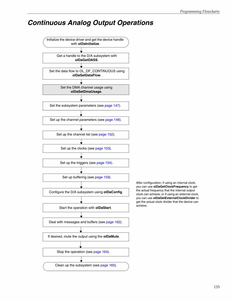
Programming Flowcharts
Continuous Analog Output Operations
Get a handle to the D/A subsystem with olDaGetDASS.
Initialize the device driver and get the device handle with olDaInitialize.
Set the subsystem parameters (see page 147).
Set the data flow to OL_DF_CONTINUOUS using olDaSetDataFlow.
Set the DMA channel usage using olDaSetDmaUsage.
Set up the channel list (see page 152).
Set up the channel parameters (see page 148).
Set up buffering (see page 159).
Configure the D/A subsystem using olDaConfig.
Deal with messages and buffers (see page 162).
Stop the operation (see page 164).
Clean up the subsystem (see page 165).
Start the operation with olDaStart.
Set up the clocks (see page 153).
After configuration, if using an internal clock, you can use olDaGetClockFrequency to get the actual frequency that the internal output clock can achieve; or if using an external clock, you can use olDaGetExternalClockDivider to get the actual clock divider that the device can achieve.
Set up the triggers (see page 154).
If desired, mute the output using the olDaMute.
133

Chapter 4
134
Continuous Digital Input Operations
Get a handle to the DIN subsystem with olDaGetDASS.
Initialize the device driver and get the device handle with olDaInitialize.
Set the data flow to OL_DF_CONTINUOUS using
olDaSetDataFlow.
Set the resolution with olDaSetResolution.
Go to the next page.
Set the trigger source to OL_TRG_SOFT using olDaSetTrigger.
olDaSetNotificationProcedure Specify the procedure to handle Windows messages.
Using main window to
handle messages?
Yes
No
olDaSetWndHandleSpecify the window in which to post messages.
Configure the subsystem using olDaConfig.
Start the operation with olDaStart.
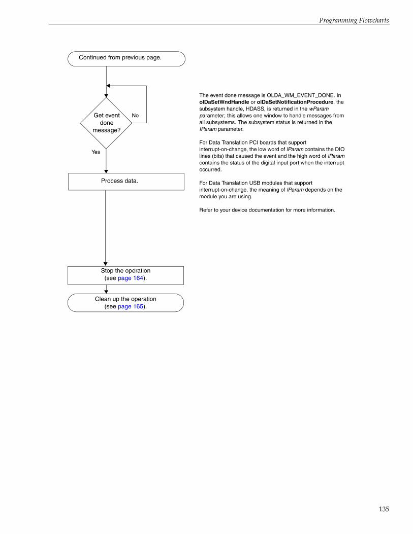
Programming Flowcharts
Continued from previous page.
Stop the operation(see page 164).
Clean up the operation(see page 165).
Get event done
message?
Yes
No
The event done message is OLDA_WM_EVENT_DONE. In olDaSetWndHandle or olDaSetNotificationProcedure, the subsystem handle, HDASS, is returned in the wParam parameter; this allows one window to handle messages from all subsystems. The subsystem status is returned in the IParam parameter.
For Data Translation PCI boards that support interrupt-on-change, the low word of lParam contains the DIO lines (bits) that caused the event and the high word of lParam contains the status of the digital input port when the interrupt occurred.
For Data Translation USB modules that support interrupt-on-change, the meaning of lParam depends on the module you are using.
Refer to your device documentation for more information.
Process data.
135
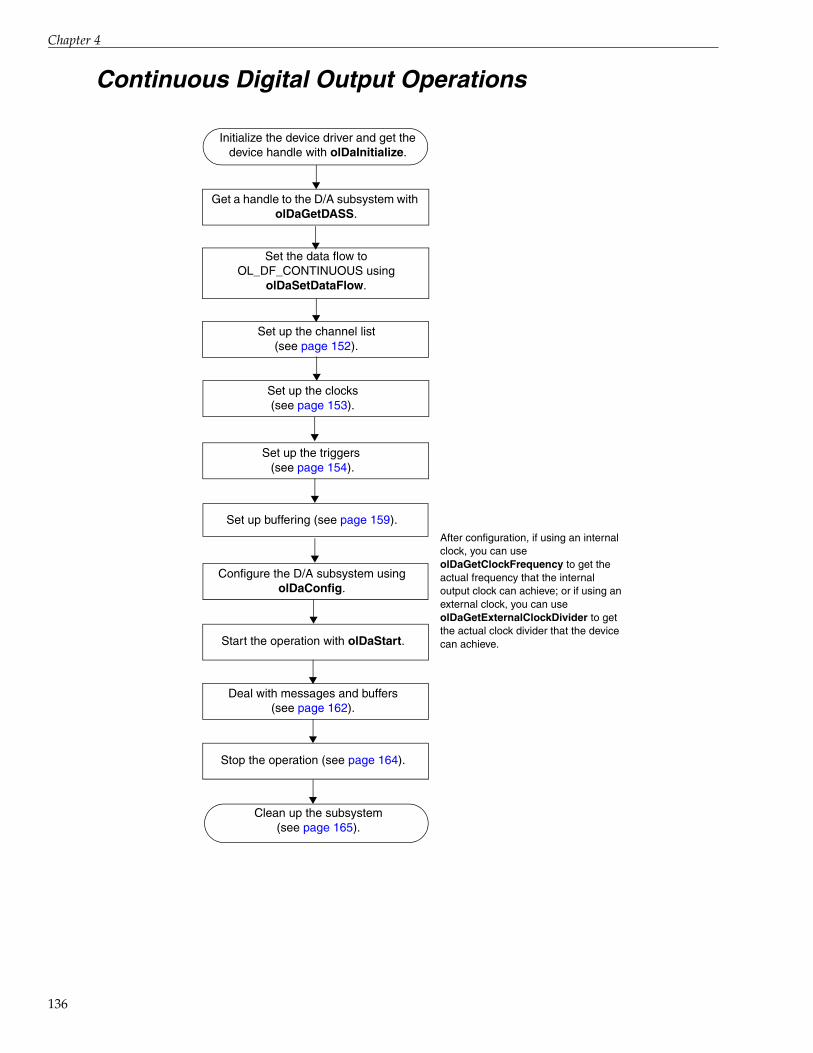
Chapter 4
136
Continuous Digital Output Operations
Get a handle to the D/A subsystem with olDaGetDASS.
Initialize the device driver and get the device handle with olDaInitialize.
Set the data flow to OL_DF_CONTINUOUS using
olDaSetDataFlow.
Set up the channel list (see page 152).
Set up buffering (see page 159).
Configure the D/A subsystem using olDaConfig.
Set up the clocks (see page 153).
After configuration, if using an internal clock, you can use olDaGetClockFrequency to get the actual frequency that the internal output clock can achieve; or if using an external clock, you can use olDaGetExternalClockDivider to get the actual clock divider that the device can achieve.
Deal with messages and buffers (see page 162).
Stop the operation (see page 164).
Clean up the subsystem (see page 165).
Start the operation with olDaStart.
Set up the triggers (see page 154).

Programming Flowcharts
Event Counting Operations
Get a handle to a general-purpose C/T subsystem with olDaGetDASS.
Initialize the device driver and get the device handle with olDaInitialize.
Set up the clocks and gates(see page 163).
Set the cascade mode using olDaSetCascadeMode.
Specify the mode as OL_CTMODE_COUNT using olDaSetCTMode.
Configure the subsystem using olDaConfig.
Start the operation using olDaStart.
Read the events counted using olDaReadEvents.
Stop the operation (see page 164).
Clean up the subsystem (see page 166).
Get update of events
total?
Yes
No
137

Chapter 4
138
Up/Down Counting Operations
Get a handle to a general-purpose C/T subsystem with olDaGetDASS.
Initialize the device driver and get the device handle with olDaInitialize.
Specify the mode as OL_CTMODE_UP_DOWN
using olDaSetCTMode.
Configure the subsystem using olDaConfig.
Specify the clock source as OL_CLK_EXTERNAL using
olDaSetClockSource.
Specify an external clock divider witholDaSetExternalClockDivider.
Start the operation using olDaStart.
Read the events counted using olDaReadEvents.
Stop the operation (see page 164).
Get update of events
total?
Yes
No
Clean up the subsystem (see page 166).

Programming Flowcharts
Frequency Measurement Operations
Note: If you need more accuracy than the system timer provides, refer to page 97.
Get a handle to a general-purpose C/T subsystem with olDaGetDASS.
Initialize the device driver and get the device handle with olDaInitialize.
Set up the clocks(see page 153).
Specify the mode as OL_CTMODE_COUNT using olDaSetCTMode.
Set the cascade mode using olDaSetCascadeMode.
Configure the subsystem using olDaConfig.
Start the frequency measurement operation using olDaMeasureFrequency.
Get measure
done message?
Yes
No
Message is in the form OLDA_WM_MEASURE_DONE.
Use the LongtoFreq (lParam) macro to get the measured
frequency value:float = Freq;
Freq = LongtoFreq (lParam);
Clean up the subsystem (see page 166).
139

Chapter 4
140
Edge-to-Edge Measurement Operations
Get a handle to a general-purpose C/T subsystem with olDaGetDASS.
Initialize the device driver and get the device handle with olDaInitialize.
Specify the mode as OL_CTMODE_MEASURE using olDaSetCTMode.
Configure the subsystem using olDaConfig.
Specify the start edge using olDaSetMeasureStartEdge.
Specify the clock source as OL_CLK_INTERNAL using
olDaSetClockSource.
Specify the stop edge using olDaSetMeasureStopEdge.
Start the operation using olDaStart.
Event done
message returned?
Yes
No
Message is in the form OLDA_WM_EVENT_DONE. Note that if you want to perform another edge-to-edge measurement, you can call olDaStart again or use the OLDA_WM_EVENT_DONE handler to call olDaStart again.
Read the value of the lParam parameter in the
OLDA_WM_EVENT_DONE message to determine the value
of the counter.
Clean up the subsystem (see page 166).

Programming Flowcharts
Continuous Edge-to-Edge Measurement Operations
Get a handle to a general-purpose C/T subsystem with olDaGetDASS.
Initialize the device driver and get the device handle with olDaInitialize.
Specify the mode as OL_CTMODE_CONT_MEASURE
using olDaSetCTMode.
Configure the subsystem using olDaConfig.
Specify the start edge using olDaSetMeasureStartEdge.
Specify the clock source as OL_CLK_INTERNAL using
olDaSetClockSource.
Specify the stop edge using olDaSetMeasureStopEdge.
Read the value of the counter/timer using olDaReadEvents or through the
channel-gain list.
No
Yes
Stop the operation (see page 164).
Clean up the subsystem (see page 166).
Read value of counter
again?
Start the operation using olDaStart.
On each read of the counter/timer, the current value of the counter/timer channel is returned and the next edge-to-edge measurement mode operation starts. If the current edge-to-edge measurement operation is still in progress, 0 is returned.
141
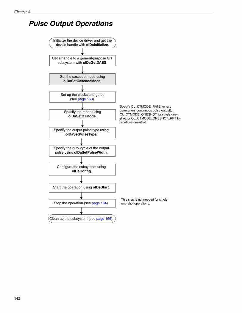
Chapter 4
142
Pulse Output Operations
Get a handle to a general-purpose C/T subsystem with olDaGetDASS.
Initialize the device driver and get the device handle with olDaInitialize.
Set up the clocks and gates(see page 163).
Set the cascade mode using olDaSetCascadeMode.
Specify the mode usingolDaSetCTMode.
Specify OL_CTMODE_RATE for rate generation (continuous pulse output), OL_CTMODE_ONESHOT for single one- shot, or OL_CTMODE_ONESHOT_RPT for repetitive one-shot.
Stop the operation (see page 164).
Specify the output pulse type using olDaSetPulseType.
Specify the duty cycle of the output pulse using olDaSetPulseWidth.
This step is not needed for single one-shot operations.
Clean up the subsystem (see page 166).
Configure the subsystem using olDaConfig.
Start the operation using olDaStart.

Programming Flowcharts
Measure Counter Operations
Initialize the device driver and get the device handle with olDaInitialize.
Get a handle to the C/T subsystem associated with the measure counter using olDaGetDASS.
Read the value of the measure counter in the analog input stream by adding the measure counter in the
analog input channel list. Follow the steps for continuous analog input operations, on page 132.
Release the subsystem using olDaReleaseDASS.
Release the device driver and terminate the session using olDaTerminate.
Configure the subsystem using olDaConfig.
Specify the start edge using olDaSetMeasureStartEdge.
Specify the stop edge using olDaSetMeasureStopEdge.
143

Chapter 4
144
Tachometer Operations
Initialize the device driver and get the device handle with olDaInitialize.
Specify the edge (rising or falling) of the tachometer for the measurement using olDaSetEdgeType.
Specify the value of the stale data flag using olDaSetStaleDataFlagEnabled.
If this flag is True, the most significant bit (MSB) of the value is set to 0 to indicate new data; reading the value before the measurement is complete returns an MSB of 1. If this flag is False, the MSB is always set to 0.
Get a handle to the TACH subsystem with olDaGetDASS.
Configure the TACH subsystem usingolDaConfig.
Read the value of the tachometer in the analog input stream by adding the tachometer in the analog input channel list. Follow the steps for
continuous analog input operations, on page 132.
Release the subsystem using olDaReleaseDASS.
Release the device driver and terminate the session using olDaTerminate.

Programming Flowcharts
Quadrature Decoder Operations
Set the clock source to OL_CLK_EXTERNAL using olDaSetClockSource
Set up the quadrature decoder operation using olDaSetQuadDecoder
Get a handle to the C/T subsystem with olDaGetDASS.
Initialize the device driver and get the device handle with olDaInitialize.
Start the operation using olDaStart.
Configure the subsystem using olDaConfig.
Get update of events
total?
Yes
No
Read the events counted using olDaReadEvents.
Stop the operation (see page 164).
Clean up the subsystem (see page 166).
145

Chapter 4
146
Simultaneous Operations
Configure the subsystem that you want to run simultaneously.
Put each subsystem to be simultaneously started on the start list
using olDaPutDassToSSList.
Prestart the subsystems on the simultaneous start list with
olDaSimultaneousPreStart.
Allocate a simultaneous start list using olDaGetSSList.
See the previous flow diagrams in this chapter; you cannot perform single-value operations simultaneously on multiplexed A/D modules.
Start the subsystems on the simultaneous start list with olDaSimultaneousStart.
Deal with messages (see page 160 for analog input operations; see page
162 for analog output operations).
Stop the operation (see page 164).
Clean up the subsystem (see page page 165 for analog I/O operations).

Programming Flowcharts
Set Subsystem Parameters
olDaSetChannelTypeSpecify the channel type (single-ended or differential). Specify single-ended if you are using pseudo-differential channels.
olDaSetResolution Specify the resolution.
olDaSetEncodingFor A/D and D/A subsystems, specify the data encoding type.
olDaSetRange
For A/D and D/A subsystems that support a single range for the entire subsystem, specify the voltage range for the entire subsystem.
olDaSetReturnCjcTemperatureInStream For A/D subsystems that support thermocouple inputs, enable or disable the ability to return CJC data in the data stream. By default, this ability is disabled.
olDaSetSyncMode For subsystems that support programmable synchronization modes, specify the synchronization mode for the subsystem (none, master, or slave).
olDaSetDataFilterType For A/D subsystems that support programmable filter types, specify the filter type for the subsystem.
olDaSetStrainExcitationVoltageSourceFor A/D subsystems that support strain gage inputs, specify the excitation voltage source
Using an internalexcitation voltagesource?
olDaSetStrainExcitationVoltage
Yes
Specify the value of the internal excitation voltage source.
147

Chapter 4
148
Set up Channel Parameters
Set channel range?
Yes
No
Use olDaSetChannelRange to set the voltage range per channel,
No
Go to next page.
YesUse olDaSetThermocoupleType to set the thermocouple
type.
No
RTD channel?
YesUse olDaSetRtdType to set the RTD type.
No
If the RTD type is Pt3850 or Custom, use olDaSetRtdR0 to set the resistance value of the RTD.
If the RTD type is Custom, use the olDaSetRtdA, olDaSetRtdB, and olDaSetRtdC to set the Callendar-Van
Dusen coefficients for the RTD type.
Thermo-couple
channel?
Use olDaSetSensorWiringConfiguration to indicate whether the RTD uses a two-wire, three-wire, or four-wire
configuration.
MultisensorChannel?
YesUse olDaSetMultiSensorType to set the sensor type for
the channel.
Voltage Input
Channel?
No
YesIf supported, use olDaSetInputTerminationEnabled to
enable or disable use of the bias return termination resistor based on the channel wiring.

Programming Flowcharts
Accelerometerchannel?
Yes
Use olDaSetCouplingType to set the coupling type to AC or DC.
Use olDaSetExcitationCurrentSource to set the excitation current source to Internal, External, or Disabled.
Use olDaSetExcitationCurrentValue to set the value of the internal excitation current
source.Excitation internal?
Yes
Go to next page.
Thermistor channel?
Yes
No
Use olDaSetThermistorA, olDaSetThermistorB, and olDaSetThermistorC to set the Steinhart-Hart coefficients for the
thermistor.
Resistance channel?
Yes
No
Use olDaSetSensorWiringConfiguration to indicate whether the resistance measurement uses a two-wire, three-wire, or four-wire
configuration.
Use olDaSetSensorWiringConfiguration to indicate whether the thermistor uses a two-wire, three-wire, or four-wire configuration.
Continued from previous page.
Use olDaSetExcitationCurrentSource to set the excitation current source to Internal, External, or Disabled.
Use olDaSetExcitationCurrentValue to set the value of the internal excitation current source based on the resistor that is used.
Excitation internal?
Yes
No
No
Currentchannel?
Yes If supported, use olDaSetInputTerminationEnabled to enable or disable use of the bias return termination resistor based on the
channel wiring.
149

Chapter 4
150
Use olDaSetStrainBridgeConfiguration to set the configuration of the strain gage.
Strain Gage channel?
Yes
Continued from previous page.
Perform shunt
calibration?
Yes Enable the shunt resistor using olDaSetStrainShuntResistor.
Read the value of the bridge in the unstrained condition using olDaGetSingleValue and supply this value later when you
convert voltage to strain using olDaVoltsToStrain.
Disable the shunt resistor using olDaSetStrainShuntResistor.
No
No
Bridgechannel?
Yes Using TEDS?
Yes Read the TEDS data from the sensor using olDaReadBridgeSensorHardwareTeds, or from a TEDS
data file using olDaReadBridgeSensorVirtualTeds.
No
Use olDaSetBridgeConfiguration to set the configuration of the bridge-based sensor or general-purpose bridge.
Using TEDS?
YesRead the TEDS data from the strain gage using
olDaReadStrainGageHardwareTeds, or from a TEDS data file using olDaReadStrainGageVirtualTeds.
No
Perform shunt
calibration?
Yes Enable the shunt resistor using olDaSetStrainShuntResistor.
Read the value of the bridge in the unstrained condition using olDaGetSingleValue and supply this value later when you
convert voltage to strain using olDaVoltsToBridgeBasedSensor.
Disable the shunt resistor using olDaSetStrainShuntResistor.
No
Go to next page.

Programming Flowcharts
Filter per Channel?
Yes
Continued from previous page.
Specify the filter for each channel using olDaSetChannelFilter.
151

Chapter 4
152
Set Up Channel List Parameters
olDaSetChannelListSizeSpecify the size of the channel list, gain list, channel inhibit list, and synchronous digitalI/O list.
olDaSetChannelListEntry Set up the channel list for the subsystem.
olDaSetGainListEntry
Specify the gain for each channel in the channel list (the gain list parallels the channel list). Use a gain of 1 for channels that do not support programmable gain.
olDaSetChannelListEntryInhibitEnable or disable inhibition for the specified channel entries. If inhibited, the acquired values from the specified entries are discarded.
olDaSetSynchronousDigitalIOUsage
Enable/disable a synchronous digital output operation. If using a DOUT subsystem that is currently in use, the handle to the DOUT subsystem must be freed with olDaReleaseDASS before configuring the this subsystem with olDaConfig.
olDaSetDigitalIOListEntryFor A/D subsystems only, specify the values to output to the dynamic digital output channels as each entry in the channel list is sampled.

Programming Flowcharts
Set Up Clocks
Specify OL_CLK_EXTERNAL to select the external clock or OL_CLK_EXTRA to select an extra available external clock.
Using aninternalclock?
olDaSetClockSource
olDaSetClockFrequency
Specify the frequency of the internal clock. The driver sets the actual frequency as closely as possible to the number specified.
olDaSetClockSource
olDaSetExternalClockDivider
Yes
No
Specify a clock divider to apply to the external clock source. The driver sets the actual clock divider as closely as possible to the number specified.
Specify OL_CLK_INTERNAL to select the internal clock or OL_CLK_EXTRA to select an extra available internal clock.
153

Chapter 4
154
Set Up Triggers
Set the reference trigger source using the olDaSetReferenceTrigger function. This trigger source stops pre-trigger acquisition, if in progress, and starts
post-trigger acquisition.
Using astart trigger and reference trigger for pre-trigger/
post-trigger operations?
Yes
No
Set the start trigger type using the olDaSetTrigger function.
Using threshold trigger for the start trigger?
Yes
Set the channel to use for the threshold trigger using the olDaSetTriggerThresholdChannel function.
Set the level of the threshold trigger using the olDaSetTriggerThresholdLevel function.
Using threshold trigger for
the reference trigger?
YesSet the channel to use for the threshold trigger using the olDaSetReferenceTriggerThresholdChannel
function.
Set the level of the threshold trigger using the olDaSetReferenceTriggerThresholdLevel function.
Specify the number of samples to acquire after the reference trigger using the olDaSetReferenceTriggerPostScanCount function.
Go to next page.

Programming Flowcharts
Set the post-trigger source using the using the olDaSetTrigger function.
Using pre-trigger or about-triggermode without a reference
trigger (legacy devices)?
Yes
Set the pre-trigger type to one of the following values (if supported by your device) using the olDaSetPretriggerSource function.
Using post-trigger or about-trigger
mode without a reference
trigger (legacy devices)?
Yes
Using threshold trigger?
Yes If supported by your device, set the channel to use for the threshold trigger using the
olDaSetTriggerThresholdChannel function.
If supported by your device, set the level of the threshold trigger using the
olDaSetTriggerThresholdLevel function.
Using threshold trigger?
Yes If supported by your device, set the channel to use for the threshold trigger using the
olDaSetTriggerThresholdChannel function.
If supported by your device, set the level of the threshold trigger using the
olDaSetTriggerThresholdLevel function.No
No
No
Go to next page.
Continued from previous page.
155

Chapter 4
156
Set the trigger source using the olDaSetTrigger function.
Yes
Using threshold trigger?
YesIf supported by your device, set the channel to use for
the threshold trigger using the olDaSetTriggerThresholdChannel function.
If supported by your device, set the level of the threshold trigger using the
olDaSetTriggerThresholdLevel function.
Continued from previous page.
Using a trigger to start analog output operations?

Programming Flowcharts
Set Up Triggered Scan
Specify the retrigger mode: OL_RETRIGGER_INTERNAL (internal retrigger clock is the retrigger; any supported trigger source is initial trigger), OL_RETRIGGER_SCAN_PER_TRIGGER (retrigger source same as initial trigger source), or OL_RETRIGGER_EXTRA (external retrigger source is the retrigger; any supported trigger source is the initial trigger).
olDaSetRetriggerMode
Specify the retrigger source. Refer to your device driver documentation for details.
Set the frequency of the retrigger clock. The driver sets the actual frequency as closely as possible to the number specified.
olDaSetTriggeredScanUsage Enable triggered scan mode.
Using internal retrigger mode?
Yes
olDaSetRetriggerFrequency
No
Using retrigger extra
mode?
Yes
No
olDaSetRetrigger
Specify the number of times to scan the channel-gain list per trigger/retrigger.
olDaSetMultiscanCount
157

Chapter 4
158
Set Up Input Buffering
Specify the procedure to handle Windows messages.
Using main window to
handle messages?
Yes
Allocate more
buffers?
Yes
olDaSetNotificationProcedure
No
Use olDmAllocBuffer to allocate a buffer of samples, where each sample is 2 bytes; use olDmCallocBuffer to allocate a buffer of samples of a specified size; or use olDmMallocBuffer to allocate a buffer in bytes.
Put the buffer on the ready queue.
olDaSetWrapMode
A minimum of three buffers is recommended for continuous input operations.
olDaSetWndHandleSpecify the window in which to post messages.
olDmAllocBuffer, olDmMallocBuffer, or
olDmCallocBuffer
olDaPutBuffer
Specify the buffer wrapping mode. If OL_WRP_NONE, data is written to multiple allocated input buffers continuously; when no more empty buffers are available, the operation stops (gap-free data guaranteed). If OL_WRP_MULTIPLE, data is written to multiple allocated input buffers continuously; if no more empty buffers are available, the device overwrites the data in the current buffer, starting with the first location in the buffer (data is not guaranteed to be gap-free).

Programming Flowcharts
Set Up Output Buffering
Specify the procedure to handle Windows messages.
Using main window to
handle messages?
Yes
Allocate more
buffers?
Yes
olDaSetNotificationProcedure
No
olDaSetWrapMode
olDaSetWndHandleSpecify the window in which to post messages.
olDmAllocBuffer, olDmMallocBuffer, or
olDmCallocBuffer
olDaPutBuffer
olDmSetValidSamples Specify the valid number of data points in the buffer.
Fill the buffer.
Use olDmAllocBuffer to allocate a buffer of samples, where each sample is 2 bytes; use olDmCallocBuffer to allocate a buffer of samples of a specified size; or use olDmMallocBuffer to allocate a buffer in bytes.
Put the buffer on the ready queue.
Specify the buffer wrapping mode. If OL_WRP_NONE, data is written from multiple output buffers continuously; when no more output buffers are available, the operation stops. If OL_WRP_MULTIPLE, data is output from multiple output buffers continuously; if no more output buffers are available, the device outputs data from the current buffer, starting with the first location in the buffer. If OL_WRP_SINGLE, data from a single output buffer is downloaded to the FIFO of the device (if supported by the device) and is written out starting from the first location of the buffer; when the end of the buffer is reached, the device starts outputting data from the first location of the buffer.
159

Chapter 4
160
Deal with Messages and Buffers for Input Operations
Get error message?
Retrieve the buffer from the done queue.
No
YesReport the error.
Get buffer reused
message?
No
Yes
You may want to increment a counter.
Get queue done
message?
No
YesReport that the operation has stopped. You might
also want to clean up the subsystem (see page 165).
Get buffer done
message?
No
Yes Process data?
No
YesolDaGetBuffer
Determine the number of samples in the buffer.olDmGetValidSamples
The following error messages can be reported: OLDA_WM_OVERRUN or OLDA_WM_TRIGGER_ERROR.
The buffer reused message is OLDA_WM_BUFFER_REUSED.
The queue done messages are OLDA_WM_QUEUE_DONE and OLDA_WM_QUEUE_STOPPED.
The buffer done message is OLDA_WM_BUFFER_DONE or OLDA_WM_PRETRIGGER_BUFFER_DONE.
Wait for message?
YesReturn to the top of
the page.
olDaPutBuffer
olDmGetBufferPtr Get a pointer to the buffer.
Process the data/buffer in your program.
olDaPutBuffer
Convert the data from counts to voltage using olDaCodeToVolts, from voltage to counts
using olDaVoltsToCode, from volts to strain using olDaVoltsToStrain, or from volts to a
value for a bridge-based sensor using olDaVoltsToBridgeBasedSensor, if desired.
Recycle the buffer if you want the subsystem to fill it again when using OL_WRP_NONE or OL_WRP_MULTIPLE. See page 161 if you want to transfer data from an inprocess buffer. For a burst of data, you may want to clean up after processing; refer to page 166 for more information.
Get IO Complete message?
Yes
Determine when the reference trigger occurred and the
number of pre-trigger samples that were
acquired by subtracting the post trigger scan count from the total
number of samples that were acquired.

Programming Flowcharts
Transfer Data from an Inprocess Buffer
olDaGetQueueSizeDetermine the number of buffers on the inprocess queue (at least one buffer must be on the inprocess queue to perform this operation).
Copy the data from the inprocess buffer to the allocated buffer for immediate processing. An OLDA_WM_BUFFER_DONE message is generated when the operation completes.
olDaFlushFromBufferInprocess
olDmAllocBuffer, olDmMallocBuffer, or
olDmCallocBuffer
See page 160 to deal with the buffers.
Use olDmAllocBuffer to allocate a buffer of samples, where each sample is 2 bytes; use olDmCallocBuffer to allocate a buffer of samples of a specified size; or use olDmMallocBuffer to allocate a buffer in bytes.
161
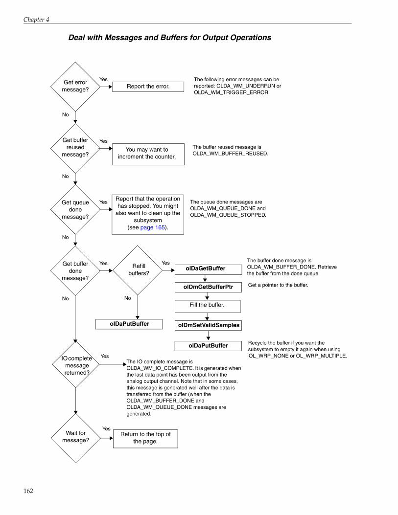
Chapter 4
162
Deal with Messages and Buffers for Output Operations
Get error message?
No
YesReport the error.
Get buffer reused
message?
No
Yes
You may want to increment the counter.
Get queue done
message?
No
YesReport that the operation has stopped. You might
also want to clean up the subsystem
(see page 165).
Get buffer done
message?
No
Yes
No
YesolDaGetBuffer
The following error messages can be reported: OLDA_WM_UNDERRUN orOLDA_WM_TRIGGER_ERROR.
The buffer reused message is OLDA_WM_BUFFER_REUSED.
The queue done messages are OLDA_WM_QUEUE_DONE and OLDA_WM_QUEUE_STOPPED.
The buffer done message is OLDA_WM_BUFFER_DONE. Retrieve the buffer from the done queue.
Refill buffers?
Wait for message?
YesReturn to the top of
the page.
IO complete message returned?
YesThe IO complete message is OLDA_WM_IO_COMPLETE. It is generated when the last data point has been output from the analog output channel. Note that in some cases, this message is generated well after the data is transferred from the buffer (when the OLDA_WM_BUFFER_DONE and OLDA_WM_QUEUE_DONE messages are generated.
olDaPutBuffer
olDmGetBufferPtr Get a pointer to the buffer.
Fill the buffer.
olDmSetValidSamples
olDaPutBuffer Recycle the buffer if you want the subsystem to empty it again when using OL_WRP_NONE or OL_WRP_MULTIPLE.

Programming Flowcharts
Set Clocks and Gates for Counter/Timer Operations
Specify OL_CLK_EXTERNAL to select the external clock or OL_CLK_EXTRA to select an extra available external clock.
Using aninternalclock?
olDaSetClockSource
Specify OL_CLK_INTERNAL to select the internal clock or OL_CLK_EXTRA to select an extra available internal clock.
olDaSetClockFrequencySpecify the frequency of the output pulse from the internal clock. The driver sets the actual frequency as closely as possible to the number specified.
olDaSetClockSource
olDaSetExternalClockDivider
Yes
No
olDaSetGateType
Specify a clock divider to apply to the external clock source to set the frequency of the output pulse. The driver sets the actual clock divider as closely as possible to this number.
Specify the gate to enable or trigger a counter/timer operation. Specify OL_GATE_NONE for a software gate, OL_GATE_HIGH_LEVEL for a high-level gate, OL_GATE_LOW_LEVEL, OL_GATE_HIGH_EDGE, OL_GATE_LOW_EDGE, OL_GATE_LEVEL for any level gate, OL_GATE_HIGH_LEVEL_DEBOUNCE for a debounced high-level gate, OL_GATE_LOW_LEVEL_DEBOUNCE, OL_GATE_HIGH_EDGE_DEBOUNCE, OL_GATE_LOW_EDGE_DEBOUNCE, or OL_GATE_LEVEL_DEBOUNCE.
163

Chapter 4
164
Stop the Operation
olDaAbort and olDaReset stop the operation on the subsystem immediately; the current buffers are not filled or emptied before they are put on the done queue. olDaReset also reinitializes the subsystem to a known state and flushes all buffers to the done queue.
Stop in an orderly way?
olDaStop
olDaStop stops the operation on the subsystem in the recommended way; the current inprocess buffers are filled or emptied and put on the done queue. The driver posts at least one buffer done and queue stopped message.
Note that olDaStop always waits for the current buffer to be filled before stopping the subsystem. Therefore, if you are using an external trigger or a threshold trigger and the trigger is never received, do not call olDaStop as the subsystem will not be stopped if it is waiting for a trigger. Instead, call olDaAbort, which stops the subsystem immediately.
olDaReset
olDaAbort
Yes
No
Reinitialize?Yes
No
Pause the operation?
Yes
No
olDaPause
Continue a paused
operation?
Yes
No
olDaContinue
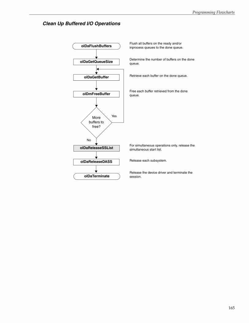
Programming Flowcharts
Clean Up Buffered I/O Operations
olDaFlushBuffersFlush all buffers on the ready and/or inprocess queues to the done queue.
olDaGetQueueSizeDetermine the number of buffers on the done queue.
olDaGetBuffer Retrieve each buffer on the done queue.
olDmFreeBufferFree each buffer retrieved from the done queue.
More buffers to
free?
Yes
No
olDaReleaseDASS Release each subsystem.
olDaTerminateRelease the device driver and terminate the session.
olDaReleaseSSListFor simultaneous operations only, release the simultaneous start list.
165

Chapter 4
166
Clean Up Counter/Timer Operations
olDaReleaseDASS Release each subsystem.
olDaTerminateRelease the device driver and terminate the session.
olDaReleaseSSListFor simultaneous operations only, release the simultaneous start list.

5Product Support
167

Chapter 5
168
Should you experience problems using the DataAcq SDK, follow these steps:
1. Read all the appropriate sections of this manual. Make sure that you have added any“Read This First” information to your manual and that you have used this information.
2. Check for a README file on the Data Acquisition OMNI CD. If present, read this file forthe latest installation and usage information.
3. Check that you have installed your hardware devices properly. For information, refer tothe documentation supplied with your devices.
4. Check that you have installed the device drivers for your hardware devices properly. Forinformation, refer to the documentation supplied with your devices.
5. Check that you have installed your software properly. For information, refer to Chapter 2starting on page 19.
If you are still having problems, Data Translation’s Technical Support Department is available to provide technical assistance. To request technical support, go to our web site at hwww.mccdaq.com and click on the Support link.
When requesting technical support, be prepared to provide the following information:
• Your product serial number
• The hardware/software product you need help on
• The version of the CD you are using
• Your contract number, if applicable
If you are located outside the USA, contact your local distributor; see our web site (www.mccdaq.com) for the name and telephone number of your nearest distributor.

ASample Code
Single-Value Analog Input . . . . . . . . . . . . . . . . . . . . . . . . . . . . . . . . . . . . . . . . . . . . . . . . . . . . 170
Continuous Analog Input . . . . . . . . . . . . . . . . . . . . . . . . . . . . . . . . . . . . . . . . . . . . . . . . . . . . . 174
169
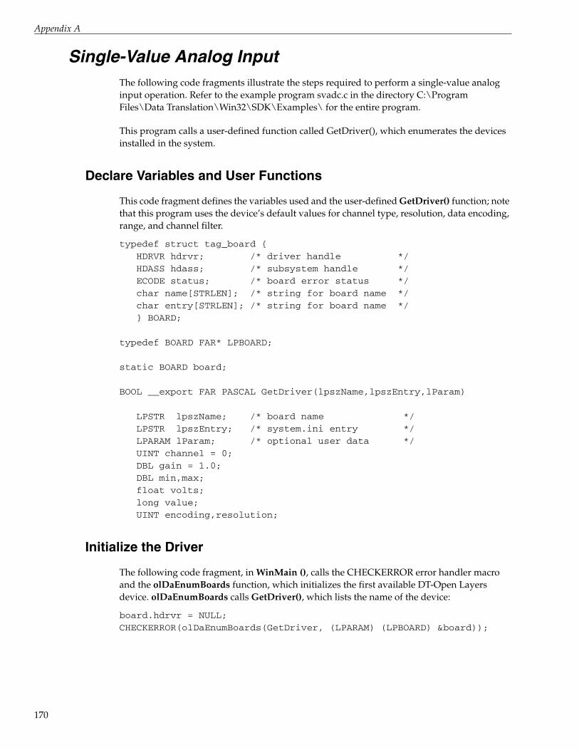
Appendix A
170
Single-Value Analog Input The following code fragments illustrate the steps required to perform a single-value analog input operation. Refer to the example program svadc.c in the directory C:\Program Files\Data Translation\Win32\SDK\Examples\ for the entire program.
This program calls a user-defined function called GetDriver(), which enumerates the devices installed in the system.
Declare Variables and User Functions
This code fragment defines the variables used and the user-defined GetDriver() function; note that this program uses the device’s default values for channel type, resolution, data encoding, range, and channel filter.
typedef struct tag_board {HDRVR hdrvr; /* driver handle */HDASS hdass; /* subsystem handle */ECODE status; /* board error status */char name[STRLEN]; /* string for board name */char entry[STRLEN]; /* string for board name */} BOARD;
typedef BOARD FAR* LPBOARD;
static BOARD board;
BOOL __export FAR PASCAL GetDriver(lpszName,lpszEntry,lParam)
LPSTR lpszName; /* board name */LPSTR lpszEntry; /* system.ini entry */LPARAM lParam; /* optional user data */UINT channel = 0;DBL gain = 1.0;DBL min,max;float volts;long value;UINT encoding,resolution;
Initialize the Driver
The following code fragment, in WinMain (), calls the CHECKERROR error handler macro and the olDaEnumBoards function, which initializes the first available DT-Open Layers device. olDaEnumBoards calls GetDriver(), which lists the name of the device:
board.hdrvr = NULL;CHECKERROR(olDaEnumBoards(GetDriver, (LPARAM) (LPBOARD) &board));

Sample Code
This code fragment is in GetDriver() and gets the device name:
{LPBOARD lpboard = (LPBOARD)(LPVOID)lParam;/* fill in board strings */lstrcpyn(lpboard->name,lpszName,STRLEN);lstrcpyn(lpboard->entry,lpszEntry,STRLEN);
This code is in WinMain() and checks for errors within the callback function:
CHECKERROR (board.status);/* check for NULL driver handle - means no boards */if (board.hdrvr == NULL){
MessageBox(HWND_DESKTOP, "No DT-Open Layer boards!!!", "Error", MB_ICONEXCLAMATION | MB_OK);
return ((UINT)NULL);}
This code fragment is in WinMain() and initializes the device:
lpboard->status = olDaInitialize(lpszName, &lpboard->hdrvr);
if (lpboard->hdrvr != NULL)return FALSE;
/* false to stop enumerating */else
return TRUE; /* true to continue */}
Get a Handle to the Subsystem
The following code fragment gets a handle to the A/D subsystem and checks for errors:
CHECKERROR(olDaGetDASS(board.hdrvr,OLSS_AD,0, &board.hdass));
Set the DataFlow to Single Value
The following code fragment sets the dataflow mode of the A/D subsystem to single value and checks for errors.
CHECKERROR (olDaSetDataFlow(board.hdass,OL_DF_SINGLEVALUE));
Configure the Subsystem
The following code fragment configures the A/D subsystem and checks for errors.
CHECKERROR (olDaConfig(board.hdass));
171

Appendix A
172
Acquire a Single Value
The following code fragment acquires a single analog input value from channel 0 of the A/D subsystem (using a gain of 1) and checks for errors.
CHECKERROR (olDaGetSingleValue(board.hdass, &value, channel, gain));
Convert the Value to Voltage
The following code fragment uses the default range, encoding, and resolution of the A/D subsystem to convert the acquired value into voltage and to check for errors. Note that this step is optional.
CHECKERROR (olDaGetRange(board.hdass,&max,&min));CHECKERROR (olDaGetEncoding(board.hdass, &encoding));CHECKERROR (olDaGetResolution(board.hdass, &resolution));
/* Convert value to volts */if (encoding != OL_ENC_BINARY)
{/* convert to offset binary by inverting the *//* sign bit */ value ^= 1L << (resolution-1);
/* zero upper bits */value &= (1L << resolution) - 1;
}volts=(float)max-(float)min)/(1L<<resolution)* value+float)min;
/* display value with message box */sprintf(str,"Single Value AD Op.\nADC Input = %.3f V", volts);MessageBox(HWND_DESKTOP, str, board.name,
MB_ICONINFORMATION | MB_OK);
Release the Subsystem and Terminate the Session
The following code fragment releases the A/D subsystem, terminates the session, and checks for errors:
CHECKERROR (olDaReleaseDASS(board.hdass));CHECKERROR (olDaTerminate(board.hdrvr));
Handle Errors
The following code fragment handles the errors from the DataAcq SDK and displays the error codes. Note that this step is optional but recommended.
#define STRLEN 80 /* String size for general text*//* manipulation. */

Sample Code
char str[STRLEN]; /* Global string for general */ /* text manipulation */
#define SHOW_ERROR(ecode) MessageBox(HWND_DESKTOP,olDaGetErrorString(ecode, str,STRLEN),
"Error", MB_ICONEXCLAMATION|MB_OK);
#define CHECKERROR(ecode) \if ((board.status = (ecode)) != OLNOERROR)\
{\SHOW_ERROR(board.status);\olDaReleaseDASS(board.hdass);\olDaTerminate(board.hdrvr);\return ((UINT)NULL);
}
173

Appendix A
174
Continuous Analog Input The following code fragments illustrate the steps required to perform a continuous (post-trigger) analog input operation. Refer to the example program contadc.c in the directory C:\Program Files\Data Translation\Win32\SDK\Examples\ for the entire program.
This program calls two user-defined functions: GetDriver(), which enumerates the devices installed in the system, and OutputBox(), which creates a dialog box to handle information and error window messages from the A/D subsystem.
Declare Variables and User Functions
This code fragment defines the variables used and the user-defined GetDriver() function; note that this program uses the device’s default values for channel type, resolution, data encoding, range, and channel filter.
typedef struct tag_board { HDRVR hdrvr; /* driver handle */ HDASS hdass; /* subsystem handle */ ECODE status; /* board error status */ HBUF hbuf; /* subsystem buffer handle */ WORD FAR* lpbuf; /* buffer pointer */ char name[STRLEN]; /* string for board name */ char entry[STRLEN]; /* string for board name */
} BOARD;
typedef BOARD FAR* LPBOARD;
static BOARD board;static ULNG count = 0;BOOL __export FAR PASCAL GetDriver(lpszName, pszEntry, lParam)
LPSTR lpszName; /* board name */ LPSTR lpszEntry; /* system.ini entry */ LPARAM lParam; /* optional user data */
BOOL __export FAR PASCAL InputBox(hDlg, message, wParam, lParam)
HWND hDlg;/* window handle of the dialog box */UINT message;/* type of message */WPARAM wParam;/* message-specific information */ LPARAM lParam;
DBL min,max;float volts;long value;ULNG samples;

Sample Code
UINT encoding,resolution;
DBL freq;UINT size,dma,gainsup;int i;
UINT channel = 0;DBL gain = 1.0;
Initialize the Driver
The following code fragment, in WinMain(), calls the CHECKERROR error handler macro and the olDaEnumBoards function, which initializes the first available DT-Open Layers device. olDaEnumBoards calls GetDriver(), which lists the name of the device:
board.hdrvr = NULL;CHECKERROR(olDaEnumBoards(GetDriver,(LPARAM)(LPBOARD)&board));CHECKERROR (board.status);
/* check for NULL driver handle - means no boards */if (board.hdrvr == NULL){
MessageBox(HWND_DESKTOP, " No Open Layer boards!!!", "Error", MB_ICONEXCLAMATION | MB_OK);
return ((UINT)NULL);}
This code is in GetDriver() and gets the device name:
{LPBOARD lpboard = (LPBOARD)(LPVOID)lParam;
/* fill in board strings */lstrcpyn(lpboard->name,lpszName,STRLEN);lstrcpyn(lpboard->entry,lpszEntry,STRLEN);}
This code is in WinMain() and initializes the device:
lpboard->status = olDaInitialize(lpszName,&lpboard->hdrvr);
if (lpboard->hdrvr != NULL)return FALSE; /* false to stop enumerating */
elsereturn TRUE; /* true to continue */
}
175

Appendix A
176
Get a Handle to the Subsystem
The following code fragment gets a handle to the A/D subsystem and checks for errors:
CHECKERROR (olDaGetDASS(board.hdrvr,OLSS_AD,0,&board.hdass));
Set the DataFlow to Continuous
The following code fragment sets the dataflow mode of the A/D subsystem to single value and checks for errors:
CHECKERROR (olDaSetDataFlow(board.hdass,OL_DF_CONTINUOUS));
Specify the Channel List and Channel Parameters
The following code fragment specifies a channel-gain list size of 1; specifies channel 0 in the channel-gain list; if the subsystem supports programmable gain, specifies a gain of 1 for this entry; and checks for errors:
/* Specify a channel-list size of 1.*/CHECKERROR (olDaSetChannelListSize(board.hdass,1));
/* Specify a channel 0 in the channel list.*/CHECKERROR (olDaSetChannelListEntry(board.hdass,0,channel));
/* Check if the subsystem supports programmable gain. */CHECKERROR (olDaGetSSCaps(board.hdass,OLSSC_SUP_PROGRAMGAIN,
gainsup));/* Set the gain for entry 0 in the channel list *//* if the board supports it. */if (gainsup)CHECKERROR (olDaSetGainListEntry(board.hdass, 0,gain));
Specify the Clocks
The following code fragment specifies the frequency of the internal A/D sample clock and checks for errors:
/* Check the maximum frequency for the internal clock */CHECKERROR(olDaGetSSCapsEx(board.hdass,OLSSCE_MAXTHROUGHPUT, &freq));
/* set 1000 Hz frequency */freq = min (1000.0, freq);CHECKERROR (olDaSetClockFrequency(board.hdass, freq));
Sample Code
Specify DMA Usage
The following code fragment specifies one DMA channel for the A/D subsystem and checks for errors:
/* Check the number of DMA channels supported. */CHECKERROR(olDaGetSSCaps(board.hdass, OLSSC_NUMDMACHANS, &dma));
/* Set one dma channel.*/dma = min (1, dma);CHECKERROR (olDaSetDmaUsage(board.hdass,dma));
Set Up Window Handle and Buffering
The following code fragment specifies a handle to the message window, set up buffers, and check for errors:
/* Specify window handle. */CLOSEONERROR (olDaSetWndHandle(board.hdass, hDlg,(UINT)NULL));
/*Specify the buffer wrap mode as multiple */CHECKERROR (olDaSetWrapMode(board.hdass, OL_WRP_MULTIPLE));
/*Specify the buffers and put them on the ready queue. */size = (UINT)freq/10; /* Specify the buffer size. */
/* Allocate three input buffers and put the buffers on the /* ready queue. */for (i=0;i<3;i++){
CHECKERROR (olDmCallocBuffer(0,0,(ULNG) size, 2,&board.hbuf));CHECKERROR (olDmGetBufferPtr(board.hbuf,(LPVOID FAR*)
&board.lpbuf));CHECKERROR (olDaPutBuffer(board.hdass, board.hbuf));
}
Configure the Subsystem
The following code fragment configures the A/D subsystem and checks for errors.
CHECKERROR (olDaConfig(board.hdass));
Start the Continuous Analog Input Operation
The following code fragment acquires a single analog input value from channel 0 of the A/D subsystem (using a gain of 1) and checks for errors:
CLOSEONERROR (olDaStart(board.hdass));
177

Appendix A
178
Deal with Messages and Buffers
The following code fragment deals with messages and buffers for the A/D subsystem:
/* Use a dialog box to collect information *//* and error messages from the subsystem. */DialogBox(hInstance, (LPCSTR)INPUTBOX, HWND_DESKTOP, InputBox);
/* This function processes messages for the input dialog box. */switch (message) {
case WM_INITDIALOG:/* message: initialize dialog box*//* set the title to the board name */ SetWindowText(hDlg,board.name);return (TRUE); /* A message was returned. */
case OLDA_WM_BUFFER_REUSED: /* message: buffer reused*/break;case OLDA_WM_BUFFER_DONE: /* message: buffer done*/
/* Get buffer off the done queue. */CHECKERROR (olDaGetBuffer(board.hdass, &board.hbuf));
/*If there is a buffer, get subsystem *//*information for code to volts conversion */if (board.hbuf != NULL){CLOSEONERROR (olDaGetRange(board.hdass,&max,&min));CLOSEONERROR (olDaGetEncoding(board.hdass,&encoding));CLOSEONERROR (olDaGetResolution (board.hdass,&resolution));
/* get max samples in input buffer */CLOSEONERROR (olDmGetMaxSamples(board.hbuf,&samples));
/* get last sample in buffer */value = board.lpbuf[samples-1];
/* Get pointer to buffer data */CHECKERROR (olDmGetBufferPtr (board.hbuf, (LPVOID FAR*)&board.lpbuf));
/* Put buffer back on the ready queue. */CHECKERROR (olDaPutBuffer(board.hdass,board.hbuf));
case OLDA_WM_QUEUE_DONE:/* using wrap multiple or none *//* if this message is received, *//* acquisition has stopped. */EndDialog(hDlg, TRUE);

Sample Code
case OLDA_WM_QUEUE_STOPPED:/* using wrap multiple or none *//* if this message is received, *//* acquisition has stopped. */EndDialog(hDlg, TRUE);
case OLDA_WM_TRIGGER_ERROR:
/* Process trigger error message */MessageBox(hDlg,"Trigger error: acquisition stopped",
"Error", MB_ICONEXCLAMATION |MB_OK);EndDialog(hDlg, TRUE);
case OLDA_WM_OVERRUN_ERROR:/* Process underrun error message */MessageBox(hDlg,"Input overrun error: acquisition stopped",
"Error", MB_ICONEXCLAMATION | MB_OK);EndDialog(hDlg, TRUE);
case WM_COMMAND:/* message: received a command */#ifdef WIN32switch ( LOWORD(wParam) ) {#elseswitch (wParam) {#endifcase IDOK:case IDCANCEL:
CLOSEONERROR (olDaAbort(board.hdass));EndDialog(hDlg, TRUE);
return (TRUE); /* Did process a message. */}break;
} return (FALSE); /* Didn't get a message */
}
Convert Values to Voltage
The following code fragment uses the default range, encoding, and resolution of the A/D subsystem to convert the acquired values into voltages and to check for errors. Note that this step is optional.
/* convert value to volts */if (encoding != OL_ENC_BINARY) {
/* convert to offset binary by inverting sign bit */value ^= 1L << (resolution-1);
/* zero upper bits */
179
Appendix A
180
value &= (1L << resolution) - 1;}volts = ((float)max-(float)min)/(1L<<resolution) *
value + (float)min;
/* display value */sprintf(str,"%.3f Volts",volts);SetDlgItemText (hDlg, IDD_VALUE, str);}
Clean Up
The following code fragment flushes the buffers, releases the subsystem, and terminates the program when the continuous A/D operation is complete:
/* Get the input buffers from the done queue and free the /* input buffers */CHECKERROR (olDaFlushBuffers(board.hdass));
for (i=0;i<3;i++){
CHECKERROR (olDaGetBuffer(board.hdass, &board.hbuf));CHECKERROR (olDmFreeBuffer(board.hbuf));
}
/* release the subsystem and terminate the session */CHECKERROR (olDaReleaseDASS(board.hdass));CHECKERROR (olDaTerminate(board.hdrvr));
Handle Errors
The following code fragment handles the errors from the DataAcq SDK and displays the error codes. Note that this step is optional but recommended.
/* Error handling macros */
#define STRLEN 80 /* String size for general text manipulation */char str[STRLEN]; /* Global string for general text manipulation. */
#define SHOW_ERROR(ecode) MessageBox(HWND_DESKTOP,olDaGetErrorString(ecode,(str,STRLEN),
"Error", MB_ICONEXCLAMATION |MB_OK);#define CHECKERROR(ecode)
if ((board.status = (ecode))!= OLNOERROR)\{\
SHOW_ERROR(board.status);\olDaReleaseDASS(board.hdass);\olDaTerminate(board.hdrvr);\
return ((UINT)NULL);}

Sample Code
#define CLOSEONERROR(ecode)if ((board.status = (ecode)) != OLNOERROR)\{\SHOW_ERROR(board.status);\olDaReleaseDASS(board.hdass);\olDaTerminate(board.hdrvr);\EndDialog(hDlg, TRUE);\return (TRUE);}
181

Appendix A
182
Index
Index
Numerics32-bit applications 1464-bit applications 14
AA coefficient 61, 62A/D subsystem 47aborting an operation
A/D 71continuous edge-to-edge measurement 106D/A 71digital input 71digital output 71edge-to-edge measurement 102event counting 95rate generation 107repetitive one-shot 111simultaneous 126up/down counting 96
about-trigger mode 75AC coupling 58aliasing 80analog event trigger 85analog input 50, 124
bridge-based sensors 63buffers 86channel list size 52channel type 51channels in the channel list 53clock sources 79coupling type 58current measurements 56data encoding 65data flow 69DMA channels 93excitation current sources 57, 58filters 68gain 66IEPE inputs 58inhibiting channels 53multisensor inputs 55post-trigger scan count 85ranges 66resistance measurements 57resolution 65
RTD inputs 61sensor wiring 57single channel 52strain gage inputs 63synchronous digital I/O values in the channel list
54thermistor inputs 62thermocouples 58trigger sources 81triggered scan mode 76voltage inputs 56
analog input channel configurationdifferential 51pseudo-differential 51single-ended 51
analog output 50, 124buffers 86channel list size 52channel type 51channels in the channel list 53clock sources 79data encoding 65data flow 69DMA channels 93filters 68gain 66ranges 66resolution 65single channel 52trigger sources 81
analog threshold (negative) trigger 83analog threshold (positive) trigger 82architecture 45autoranging 39, 70
BB coefficient 61, 62binary data format 65bridge type 64bridge types 64bridge-based sensors 63buffer list management functions 43buffer management functions 42buffers 86
done queue 89flowcharts 160, 162
183

Index
184
inprocess queue 88ready queue 87transferring data from an inprocess buffer 161wrap modes 91
CC coefficient 61, 62C/T clock sources 112
external C/T clock 113extra C/T clock 114internal C/T clock 113internally cascaded C/T clock 113
C/T subsystem 47calibration 48calling conventions 18capabilities
used with olDaGetSSCaps 22used with olDaGetSSCapsEx 30
cascading counters 113channel list
inhibition 53size 52specification 53specifying synchronous digital I/O values 54
channel type 51channels, setting up parameters 148CJC source
external 60internal 60
CJC values in data stream 60cleaning up operations
A/D 165counter/timer 166D/A 165digital I/O 165
clock input signal 94clock sources
external 80, 138external C/T clock 113extra 81extra C/T clock 114internal 80, 140, 141internal C/T clock 113internally cascaded C/T clock 113
coefficientsA 61, 62B 61, 62C 61, 62R0 61, 62
configuration functions 31
configuring a subsystem 48continuing an operation
A/D 71D/A 71digital input 71digital output 71
continuous edge-to-edge measurement operationsflowcharts 141
continuous operations 71continuous (post-trigger) mode 73continuous about-trigger mode 75continuous pre- and post-trigger using a start and
reference trigger 72continuous pre-trigger mode 74flowcharts for A/D 132flowcharts for D/A 133flowcharts for digital input 132, 134flowcharts for digital output 133, 136sample code for continuous A/D 174
continuous pulse output 107conventions used 10conventions, calling 18conversion rate 77, 78correcting thermocouple data 60count, scan 85counter/timer operations 94
C/T clock sources 112channels 94duty cycle 117gate types 114operation modes 94pulse output types 117
counting events 95, 96, 100, 103coupling type 58creating 32-bit applications 14creating 64-bit applications 14current measurements 56current sources and values 57, 58
DD/A subsystem 47data acquisition functions 20
configuration 31conversion 41information 20initialization and termination 30operation 39
data buffers 86data conversion functions 41data encoding 65

Index
data flow modes 69data management functions 42
buffer list management 43buffer management 42
data transfer, from an inprocess buffer 161DC coupling 58debounced gate type
any level 117high-edge 116high-level 116low-edge 116low-level 116
device, initialization 47differential inputs 51digital event trigger 85digital input 50, 124
buffers 86channel list size 52channel type 51clock sources 79data flow 69DMA channels 93gain 66resolution 65single channel 52specifying the channels in the channel list 53trigger sources 81
digital output 50, 124buffers 86channel list size 52channel type 51clock sources 79data flow 69DMA channels 93gain 66resolution 65single channel 52specifying the channels in the channel list 53trigger sources 81
DIN subsystem 47DMA channels 93done queue 89DOUT subsystem 47DT-Open Layers 12duty cycle 117
Eedge-to-edge measurement operations 100
continuous 103flowcharts 140
encoding 65error checking 128error codes 49event counting operations 95
flowcharts 137event trigger
analog 85digital 85timer 85
example programs 16excitation current sources and values 57, 58excitation voltage source 63excitation voltage value 63external analog threshold (negative) trigger 83external analog threshold (positive) trigger 82external C/T clock 113external clock 138
source 80external digital (TTL) trigger 82external excitation current source 57, 58external retrigger mode 77extra C/T clock 114extra clock sources 81extra retrigger mode 78extra trigger sources 85
Ffilters 68floating-point values 59, 62, 63flowcharts 127
cleaning up A/D operations 165cleaning up counter/timer operations 166cleaning up D/A operations 165cleaning up digital I/O operations 165continuous A/D operations 132continuous D/A operations 133continuous digital input operations 132, 134continuous digital output operations 133, 136continuous edge-to-edge measurement
operations 141dealing with messages and buffers 160, 162edge-to-edge measurement operations 140event counting operations 137frequency measurement operations 139pulse output operations 142quadrature decoder 145setting up buffers for A/D operations 158setting up buffers for D/A operations 159setting up buffers for digital input operations 158
185

Index
186
setting up buffers for digital output operations 159
setting up channel lists 152setting up channel parameters 148setting up clocks 153, 163setting up gates 163setting up subsystem parameters 147setting up triggered scans 157setting up triggers 154simultaneous operations 146single-value input operations 129single-value output operations 131stopping operations 164tachometer 143, 144transferring data from an inprocess buffer 161up/down counting operations 138
frequency measurement operations 97flowcharts 139using a pulse of a known duration 98using the Windows timer 97
functionsbuffer list management 43buffer management 42configuration 31data conversion 41information 20initialization and termination 30operation 39summary 19
Ggain list 67gains 66gate input signal 94, 114gate types 114
any level 115high-edge 115high-edge, debounced 116high-level 115high-level, debounced 116level, debounced 117low-edge 115low-edge, debounced 116low-level 115low-level, debounced 116software 114
Hhandling errors 49
handling messages 49help, launching online 15high-edge gate type 115high-edge, debounced gate type 116high-level debounced gate type 116high-level gate type 115high-to-low pulse output 117
IIEPE inputs 57, 58information functions 20inhibiting channels 53initialization functions 30initializing a device 47inprocess buffer, transferring data 161inprocess queue 88input configuration
differential analog 51single-ended analog 51
internal C/T clock 113internal clock 140, 141
sources 80internal excitation current source and values 57, 58internal retrigger mode 77internal trigger 82
Llevel gate type 115level, debounced gate type 117linearization 60list management functions 43LongtoFreq macro 139, 140low-edge gate type 115low-edge, debounced gate type 116low-level gate type 115low-level, debounced gate type 116low-to-high pulse output 117
Mmacro 139, 140measure counter operations 119measuring frequency 97message handling 49
flowcharts for A/D 160flowcharts for D/A 162flowcharts for digital input 160flowcharts for digital output 162

Index
messagesOLDA_WM_BUFFER_DONE 89OLDA_WM_BUFFER_REUSED 91OLDA_WM_MEASURE_DONE 98OLDA_WM_PRETRIGGER_BUFFER_DONE 89OLDA_WM_QUEUE_DONE 91OLDA_WM_QUEUE_STOPPED 89
multiple wrap mode 91multisensor inputs 55muting the output 71
Nno wrap mode 91Nyquist Theorem 80
OOL_ENUM_CHANNEL_SUPPORTED_
MULTISENSOR_TYPES 55OL_ENUM_EXCITATION_CURRENT_VALUES
57, 58OL_ENUM_FILTERS 68OL_ENUM_GAINS 67OL_ENUM_RANGES 66OL_ENUM_THRESHOLD_REFERENCE_
TRIGGER_CHANNELS 83, 84OL_ENUM_THRESHOLD_START_TRIGGER_
CHANNELS 83, 84OLCHANNELCAP_SUP_INPUT_
TERMINATION 56OLDA_WM_BUFFER_DONE 89, 160, 162OLDA_WM_BUFFER_REUSED 91, 160, 162OLDA_WM_EVENT_DONE 49, 79, 135OLDA_WM_IO_COMPLETE 49, 89, 162OLDA_WM_MEASURE_DONE 49, 98OLDA_WM_OVERRUN 160OLDA_WM_PRETRIGGER_BUFFER_DONE 89,
160OLDA_WM_QUEUE_DONE 91, 160, 162OLDA_WM_QUEUE_STOPPED 89, 160, 162OLDA_WM_TRIGGER_ERROR 77, 78, 160, 162OLDA_WM_UNDERRUN 162olDaAbort 164
in A/D operations 71in continuous edge-to-edge measurement
operations 106in D/A operations 71in digital input operations 71in digital output operations 71in edge-to-edge measurement operations 102
in event counting operations 95in rate generation operations 107in repetitive one-shot operations 111in simultaneous operations 126in up/down counting operations 96
olDaAutoCalibrate 40, 49olDaCodeToVolts 41, 69, 90, 160olDaConfig 39, 48, 71
in continuous A/D operations 132in continuous D/A operations 133, 136in continuous digital input operations 132, 134in continuous digital output operations 133, 136in edge-to-edge measurement operations 140,
141, 143in event counting operations 137, 144, 145in frequency measurement operations 139in pulse output operations 142in single-value operations 129, 131in up/down counting operations 138
olDaContinue 40, 164in A/D operations 71in D/A operations 71in digital input operations 71in digital output operations 71
olDaEnumBoards 20, 47, 128olDaEnumBoardsEx 20olDaEnumChannelCaps 55, 21olDaEnumLists 43olDaEnumSSCaps 21, 128olDaEnumSSList 21olDaEnumSubSystems 20, 48, 128olDaFlushBuffers 40, 91, 165olDaFlushFromBufferInprocess 40, 88, 90, 161olDaFreeBuffer 91olDaGetBoardInfo 20, 47olDaGetBridgeConfiguration 35, 64olDaGetBuffer 40, 90, 165
in continuous A/D operations 160in continuous D/A operations 162in continuous digital input operations 160in continuous digital output operations 162
olDaGetCascadeMode 37olDaGetChannelCaps 21, 56olDaGetChannelFilter 33olDaGetChannelListEntry 32olDaGetChannelListEntryInhibit 32olDaGetChannelListSize 32olDaGetChannelRange 33olDaGetChannelType 32olDaGetCjcTemperature 39, 70, 130olDaGetCjcTemperatures 39, 70, 129
187

Index
188
olDaGetClockFrequency 34olDaGetClockSource 34olDaGetCouplingType 35olDaGetCTMode 37olDaGetDASS 30, 48
in continuous A/D operations 132in continuous D/A operations 133, 136in continuous digital input operations 132, 134in continuous digital output operations 133, 136in edge-to-edge measurement operations 140, 141in event counting operations 137, 144, 145in frequency measurement operations 139in pulse output operations 142, 143in single-value operations 129, 131in up/down counting operations 138
olDaGetDASSInfo 21olDaGetDataFilterType 33, 69olDaGetDataFlow 31olDaGetDevCaps 20, 48, 128olDaGetDeviceName 20olDaGetDigitalIOListEntry 32olDaGetDmaUsage 31olDaGetDriverVersion 21olDaGetEdgeType 38, 124olDaGetEncoding 33olDaGetErrorString 21olDaGetExcitationCurrentValue 35olDaGetExternalClockDivider 34olDaGetGainListEntry 32olDaGetGateType 37olDaGetInputTerminationEnabled 37, 56olDaGetMeasureStartEdge 37olDaGetMeasureStopEdge 37olDaGetMultiscanCount 32olDaGetMultiSensorType 56, 34olDaGetNotificationProcedure 31olDaGetPretriggerSource 34olDaGetPulseType 37olDaGetPulseWidth 37olDaGetQueueSize 21, 161, 165olDaGetRange 33olDaGetReferenceTrigger 33olDaGetReferenceTriggerPostScanCount 34olDaGetReferenceTriggerPostScanCount
property 86olDaGetReferenceTriggerThresholdChannel 34,
83, 84olDaGetReferenceTriggerThresholdLevel 34, 83,
84olDaGetResolution 33olDaGetRetrigger 34
olDaGetRetriggerFrequency 32olDaGetRetriggerMode 32olDaGetReturnCjcTemperatureInStream 36olDaGetRtdA 62olDaGetRtdB 36, 62olDaGetRtdC 36, 62olDaGetRtdR0 35, 36, 62olDaGetRtdType 35, 62olDaGetSensorWiringConfiguration 36, 57, 62, 63olDaGetSingleFloat 39, 70, 130olDaGetSingleFloats 39, 70, 129olDaGetSingleValue 39, 69, 130, 150olDaGetSingleValueEx 39, 70, 130olDaGetSingleValues 39, 70, 129olDaGetSSCaps 20, 128olDaGetSSCapsEx 21, 128olDaGetSSList 41, 126, 146olDaGetStaleDataFlagEnabled 38, 124olDaGetStrainBridgeConfiguration 35, 64olDaGetStrainExcitationVoltage 35olDaGetStrainExcitationVoltageSource 35olDaGetStrainShuntResistor 35olDaGetSynchronousDigitalIOUsage 32olDaGetSyncMode 37olDaGetTempFilterType 69olDaGetThermistorA 62olDaGetThermistorB 36, 62olDaGetThermistorC 36, 62olDaGetThermistorR0 36olDaGetThermocoupleType 36olDaGetTrigger 33olDaGetTriggeredScanUsage 32olDaGetTriggerThresholdChannel 33, 83, 84olDaGetTriggerThresholdLevel 33, 83, 84olDaGetVersion 21olDaGetWndHandle 31olDaGetWrapMode 31olDaInitialize 30, 47
in continuous A/D operations 132in continuous D/A operations 133, 136in continuous digital input operations 132, 134in continuous digital output operations 133, 136in edge-to-edge measurement operations 140, 141in event counting operations 137, 143, 144, 145in frequency measurement operations 139in pulse output operations 142in single-value operations 129, 131in up/down counting operations 138
olDaIsRunning 21, 71olDaMeasureFrequency 40, 97, 139olDaMultiSensorType 148

Index
olDaMute 40in D/A operations 71, 133
olDaPause 40, 164in A/D operations 71in D/A operations 71in digital input operations 71in digital output operations 71
olDaPutBuffer 40, 87, 90in continuous A/D operations 158, 160in continuous D/A operations 159, 162in continuous digital input operations 160in continuous digital output operations 159, 162
olDaPutDassToSSList 41, 126, 146olDaPutSingleValue 39, 70, 131olDaPutSingleValues 39, 70, 131olDaReadBridgeSensorHardwareTeds 65, 150olDaReadBridgeSensorVirtualTeds 65, 150olDaReadEvents 40, 95, 96, 102, 106, 137, 138, 145
in continuous edge-to-edge measurement operations 141
olDaReadStrainGageHardwareTeds 65, 150olDaReadStrainGageVirtualTeds 65olDaReadStrainGageVirtualTeds 150olDaReleaseDASS 31, 49, 126
in A/D operations 165in counter/timer operations 166in D/A operations 165in digital input operations 165in digital output operations 165in single-value operations 130, 131in tachometer operations 143, 144
olDaReleaseSSList 41, 126, 165, 166olDaReset 40, 164
in A/D operations 71in continuous edge-to-edge measurement
operations 106in D/A operations 71in digital input operations 71in digital output operations 71in edge-to-edge measurement operations 102in event counting operations 95in rate generation operations 107in repetitive one-shot operations 111in simultaneous operations 126in up/down counting operations 96
olDaSetBridgeConfiguration 35, 64, 150olDaSetCascadeMode 37, 113
in event counting operations 137in frequency measurement operations 139in pulse output operations 142
olDaSetChannelFilter 33, 68, 151
olDaSetChannelListEntry 32, 53, 152olDaSetChannelListEntryInhibit 32, 53, 152olDaSetChannelListSize 32, 52, 152olDaSetChannelRange 33, 66, 148olDaSetChannelType 32, 51, 147olDaSetClockFrequency 34, 80, 107, 113, 153
in C/T operations 163olDaSetClockSource 34, 80, 113, 138, 140, 141,
145, 153in C/T operations 163
olDaSetCouplingType 35, 58, 149olDaSetCTMode 37
in continuous edge-to-edge measurement operations 105
in edge-to-edge measurement operations 101, 140, 141
in event counting operations 95, 99, 137in frequency measurement operations 139in one-shot mode 98in one-shot operations 97, 109in pulse output operations 142in rate generation operations 107in repetitive one-shot operations 111in up/down counting operations 96, 138
olDaSetDataFilterType 33, 68, 147olDaSetDataFlow 31, 134
in continuous (post-trigger) operations 72, 73in continuous A/D operations 132in continuous about-trigger operations 75in continuous D/A operations 133, 136in continuous digital input operations 132in continuous digital output operations 133, 136in continuous pre-trigger operations 74in single-value operations 69, 129, 131
olDaSetDigitalIOListEntry 32, 54, 152olDaSetDmaUsage 31, 93
in continuous A/D operations 132in continuous D/A operations 133in continuous digital input operations 132in continuous digital output operations 133
olDaSetEdgeType 38, 124, 144olDaSetEncoding 33, 65, 147olDaSetExcitationCurrentSource 35, 57, 58, 149olDaSetExcitationCurrentValue 35, 57, 58, 149olDaSetExternalClockDivider 34, 80, 107, 113,
138, 153in C/T operations 163
olDaSetGainListEntry 32, 67, 152olDaSetGateType 37, 114, 163olDaSetInputTerminationEnabled 37, 56, 148, 149olDaSetMeasureStartEdge 37, 140, 141, 143
189
Index
190
olDaSetMeasureStopEdge 37, 140, 141, 143olDaSetMultiscanCount 32, 76, 157olDaSetMultiSensorType 56, 34olDaSetNotificationProcedure 31, 49, 134
in continuous A/D operations 158in continuous D/A operations 159in continuous digital input operations 158in continuous digital output operations 159
olDaSetPretriggerSource 34, 75, 81, 155olDaSetPulseType 37, 117, 142olDaSetPulseWidth 37, 117, 142olDaSetQuadDecoder 37, 123, 145olDaSetRange 33, 66, 147olDaSetReferenceTrigger 33, 72, 81, 154olDaSetReferenceTriggerPostScanCount 34, 72,
85, 154olDaSetReferenceTriggerThresholdChannel 34,
72, 83, 84, 154olDaSetReferenceTriggerThresholdLevel 34, 72,
83, 84, 154olDaSetResolution 33, 65, 147
in continuous digital input operations 134olDaSetRetrigger 34, 78, 81, 157olDaSetRetriggerFrequency 32, 77, 157olDaSetRetriggerMode 32, 77, 78, 157olDaSetReturnCjcTemperatureInStream 36, 60,
147olDaSetRtdA 36, 61, 148olDaSetRtdB 36, 61, 148olDaSetRtdC 36, 61, 148olDaSetRtdR0 35, 61, 148olDaSetRtdType 35, 61, 148olDaSetSensorWiringConfiguration 62, 63, 36,
57, 148, 149olDaSetStaleDataFlagEnabled 38, 124olDaSetStrainBridgeConfiguration 35, 64, 150olDaSetStrainExcitationVoltage 35, 63, 147olDaSetStrainExcitationVoltageSource 35, 63, 147olDaSetStrainShuntResistor 35, 64, 150olDaSetSynchronousDigitalIOUsage 32, 54, 152olDaSetSyncMode 37, 86, 147olDaSetTempFilterType 69olDaSetThermistorA 36, 62, 149olDaSetThermistorB 36, 62, 149olDaSetThermistorC 36, 62, 149olDaSetThermocoupleType 36, 59, 148olDaSetTrigger 33, 72, 74, 81, 134, 154, 155, 156olDaSetTriggeredScanUsage 32, 76, 157olDaSetTriggerThresholdChannel 33, 72, 83, 84,
154, 155, 156
olDaSetTriggerThresholdLevel 33, 72, 83, 84, 154, 155, 156
olDaSetWndHandle 31, 49, 134in continuous A/D operations 158in continuous D/A operations 159in continuous digital input operations 158in continuous digital output operations 159
olDaSetWrapMode 31, 91in continuous A/D operations 158in continuous D/A operations 159in continuous digital input operations 158in continuous digital output operations 159
olDaSimultaneousPreStart 41, 126, 146olDaSimultaneousStart 41, 126, 146olDaStaleDataFlagEnabled 144olDaStart 40, 134
in A/D operations 71, 132in D/A operations 71, 133, 136in digital input operations 71, 132in digital output operations 71, 133, 136in edge-to-edge measurement operations 102,
140, 141in event counting operations 95, 137, 145in one-shot operations 110in pulse output operations 142in rate generation operations 107in repetitive one-shot operations 111in simultaneous operations 126in up/down counting operations 96, 138
olDaStop 40, 164in A/D operations 71in continuous edge-to-edge measurement
operations 106in D/A operations 71in digital input operations 71in digital output operations 71in edge-to-edge measurement operations 102in event counting operations 95in rate generation operations 107in repetitive one-shot operations 111in simultaneous operations 126in up/down counting operations 96
olDaTerminate 31, 49, 126, 165in C/T operations 166in digital input operations 165in digital output operations 165in single-value operations 130, 131in tachometer operations 143, 144
olDaUnMute 40in D/A operations 71

Index
olDaVoltsToBridgeBasedSensor 41, 63, 90, 150, 160
olDaVoltsToCode 41, 69, 90, 160olDaVoltsToStrain 41, 63, 90, 150, 160olDmAllocBuffer 42, 87
in A/D operations 158in D/A operations 159in digital input operations 158in digital output operations 159in inprocess buffer operations 161
olDmCallocBuffer 42, 87in A/D operations 158in D/A operations 159in digital input operations 158in digital output operations 159in inprocess buffer operations 161
olDmCopyBuffer 42olDmCopyFromBuffer 42olDmCopyToBuffer 42olDmCreateList 43olDmEnumBuffers 43olDmFreeBuffer 42, 165olDmFreeList 43olDmGetBufferFromList 43olDmGetBufferPtr 42, 90
in continuous A/D operations 160in continuous D/A operations 162in continuous digital input operations 160in continuous digital output operations 162
olDmGetBufferSize 42olDmGetDataBits 42olDmGetDataWidth 42olDmGetErrorString 43olDmGetListCount 43olDmGetListHandle 43olDmGetListIDs 44olDmGetMaxSamples 43olDmGetTimeDateStamp 43olDmGetValidSamples 43
in continuous A/D operations 160in continuous digital input operations 160
olDmGetVersion 43olDmMallocBuffer 43, 87
in A/D operations 158in D/A operations 159in digital input operations 158in digital output operations 159in inprocess buffer operations 161
olDmPeekBufferFromList 44olDmPutBufferToList 44olDmReAllocBuffer 43
olDmReCallocBuffer 43olDmReMallocBuffer 43olDmSetDataWidth 42olDmSetValidSamples 43, 159
in continuous D/A operations 162in continuous digital output operations 162
OLSCC_SUP_SEQUENTIAL_CGL 52OLSS_SUP_EXTCLOCK 26OLSS_SUP_RETRIGGER_INTERNAL 23, 77OLSS_SUP_RETRIGGER_SCAN_PER_TRIGGER
23, 77OLSSC_CGLDEPTH 23, 52OLSSC_FIFO_SIZE_IN_K 29, 92OLSSC_FIXED_PULSE_WIDTH 28, 117OLSSC_MAX_EXCITATION_VOLTAGE 30OLSSC_MAXDICHANS 24OLSSC_MAXDIGITALIOLIST_VALUE 23, 54OLSSC_MAXMULTISCAN 23, 76OLSSC_MAXSECHANS 51OLSSC_MIN_EXCITATION_VOLTAGE 30OLSSC_NONCONTIGUOUS_CHANNELNUM 23OLSSC_NUM_DMACHANS 93OLSSC_NUM_EXCITATION_CURRENT_
VALUES 26, 57, 58OLSSC_NUM_RANGES 66OLSSC_NUM_RESOLUTION 65OLSSC_NUMCHANNELS 24, 50OLSSC_NUMDMACHANS 22OLSSC_NUMEXTRACLOCKS 26, 81, 114OLSSC_NUMEXTRATRIGGERS 25, 85OLSSC_NUMFILTERS 24, 68OLSSC_NUMGAINS 23, 67OLSSC_NUMRANGES 24OLSSC_NUMRESOLUTIONS 24OLSSC_RANDOM_CGL 52OLSSC_RETURNS_FLOATS 24, 59, 62, 63OLSSC_RETURNS_OHMS 27OLSSC_SUP_2SCOMP 24, 65OLSSC_SUP_AC_COUPLING 26, 58OLSSC_SUP_ANALOGEVENTTRIG 25, 85OLSSC_SUP_AUTOCAL 29, 48OLSSC_SUP_BINARY 24, 65OLSSC_SUP_BRIDGEBASEDSENSORS 27, 63OLSSC_SUP_BUFFERING 22, 86OLSSC_SUP_CASCADING 28, 113OLSSC_SUP_CHANNELLIST_INHIBIT 23, 53OLSSC_SUP_CJC_SOURCE_CHANNEL 27, 60OLSSC_SUP_CJC_SOURCE_INTERNAL 27, 60OLSSC_SUP_CONTINUOUS 22, 72, 73OLSSC_SUP_CONTINUOUS_ABOUTTRIG 22, 75OLSSC_SUP_CONTINUOUS_PRETRIG 22, 74
191

Index
192
OLSSC_SUP_CTMODE_CONT_MEASURE 28, 103, 119
OLSSC_SUP_CTMODE_COUNT 28, 95, 97OLSSC_SUP_CTMODE_MEASURE 28, 100OLSSC_SUP_CTMODE_ONESHOT 28, 109OLSSC_SUP_CTMODE_ONESHOT_RPT 28, 111OLSSC_SUP_CTMODE_RATE 28, 107OLSSC_SUP_CTMODE_UP_DOWN 28, 96OLSSC_SUP_CURRENT 26, 56OLSSC_SUP_CURRENT_OUTPUTS 24OLSSC_SUP_DATA_FILTERS 24OLSSC_SUP_DC_COUPLING 26OLSSC_SUP_DIFFERENTIAL 24, 51OLSSC_SUP_DIGITALEVENTTRIG 25, 85OLSSC_SUP_EXP2896 24, 51OLSSC_SUP_EXP727 24, 51OLSSC_SUP_EXTCLOCK 80, 113OLSSC_SUP_EXTERNAL_EXCITATION_
CURRENT_SOURCE 26, 57, 58OLSSC_SUP_EXTERNAL_EXCITATION_
VOLTAGE_SOURCE 28, 63OLSSC_SUP_EXTERNTRIG 25, 82OLSSC_SUP_EXTERNTTLNEG_REFERENCE_
TRIG 25, 82OLSSC_SUP_EXTERNTTLPOS_REFERENCE_
TRIG 25, 82OLSSC_SUP_FIFO 29, 92OLSSC_SUP_FILTERPERCHAN 24, 68OLSSC_SUP_GAPFREE_DUALDMA 22, 93OLSSC_SUP_GAPFREE_NODMA 22, 93OLSSC_SUP_GAPFREE_SINGLEDMA 22, 93OLSSC_SUP_GATE_GATE_LEVEL 29OLSSC_SUP_GATE_HIGH_EDGE 29, 115OLSSC_SUP_GATE_HIGH_EDGE_DEBOUNCE
29, 116, 117OLSSC_SUP_GATE_HIGH_LEVEL 29, 115OLSSC_SUP_GATE_HIGH_LEVEL_DEBOUNCE
29, 116OLSSC_SUP_GATE_LEVEL 116OLSSC_SUP_GATE_LEVEL_DEBOUNCE 29OLSSC_SUP_GATE_LOW_EDGE 29, 115OLSSC_SUP_GATE_LOW_EDGE_DEBOUNCE 29OLSSC_SUP_GATE_LOW_LEVEL 29, 115OLSSC_SUP_GATE_LOW_LEVEL_DEBOUNCE
29OLSSC_SUP_GATE_NONE 29, 114OLSSC_SUP_IEPE 26, 58OLSSC_SUP_INPROCESSFLUSH 22, 88OLSSC_SUP_INTCLOCK 26, 80, 113OLSSC_SUP_INTERLEAVED_CJC_IN_STREAM
27, 60
OLSSC_SUP_INTERNAL_EXCITATION_CURRENT_SOURCE 26, 57, 58
OLSSC_SUP_INTERNAL_EXCITATION_SOURCE 63
OLSSC_SUP_INTERNAL_EXCITATION_VOLTAGE_SOURCE 27
OLSSC_SUP_INTERRUPT 29, 79OLSSC_SUP_MAXRETRIGGER 30OLSSC_SUP_MAXSECHANS 24OLSSC_SUP_MINRETRIGGER 30OLSSC_SUP_MULTISENSOR 26, 55OLSSC_SUP_MUTE 71OLSSC_SUP_PAUSE 22, 71OLSSC_SUP_PLS_HIGH2LOW 28, 29, 117, 124OLSSC_SUP_PLS_LOW2HIGH 28, 29, 117, 124OLSSC_SUP_POST_REFERENCE_TRIG_
SCANCOUNT 25, 85OLSSC_SUP_POSTMESSAGE 22, 49OLSSC_SUP_PROCESSOR 29OLSSC_SUP_PROGRAMGAIN 23, 67OLSSC_SUP_QUADRATURE_DECODER 28OLSSC_SUP_RANDOM_CGL 23OLSSC_SUP_RANGEPERCHANNEL 24, 66OLSSC_SUP_REMOTE_SENSE 27OLSSC_SUP_RESISTANCE 26, 57OLSSC_SUP_RETRIGGER_EXTRA 23, 78OLSSC_SUP_RTDS 27, 61OLSSC_SUP_SEQUENTIAL_CGL 23OLSSC_SUP_SHUNT_CALIBRATION 27, 64OLSSC_SUP_SIMULTANEOUS_CLOCKING 26,
79OLSSC_SUP_SIMULTANEOUS_SH 23, 52, 70OLSSC_SUP_SIMULTANEOUS_START 22, 126OLSSC_SUP_SINGLEENDED 24, 51OLSSC_SUP_SINGLEVALUE 22, 69OLSSC_SUP_SINGLEVALUE_AUTORANGE 23,
70OLSSC_SUP_SOFTTRIG 25, 82OLSSC_SUP_STALE_DATA_FLAG 29OLSSC_SUP_STRAIN_GAGE 27, 63OLSSC_SUP_SV_NEG_EXTERN_TTLTRIG 82OLSSC_SUP_SV_POS_EXTERN_TTLTRIG 25, 82OLSSC_SUP_SWCAL 29OLSSC_SUP_SWRESOLUTION 24, 65OLSSC_SUP_SYNCBUS_REFERENCE_TRIG 25,
84OLSSC_SUP_SYNCHRONIZATION 22, 86OLSSC_SUP_SYNCHRONOUS_DIGITALIO 23,
54OLSSC_SUP_TEMP_FILTERS 68

Index
OLSSC_SUP_TEMPERATURE_DATA_IN_STREAM 27, 60
OLSSC_SUP_THERMISTOR 27, 62OLSSC_SUP_THERMOCOUPLES 27, 58OLSSC_SUP_THRESHNEG_REFERENCE_TRIG
25, 84OLSSC_SUP_THRESHPOS_REFERENCE_TRIG
25, 82OLSSC_SUP_THRESHTRIGNEG 25, 83OLSSC_SUP_THRESHTRIGPOS 25, 82OLSSC_SUP_TIMEREVENTTRIG 25, 85OLSSC_SUP_TRIGSCAN 23, 76OLSSC_SUP_WAVEFORM_MODE 22OLSSC_SUP_WRPMULTIPLE 22, 92OLSSC_SUP_WRPSINGLE 22, 92OLSSC_SUP_WRPWAVEFORM_ONLY 22, 92OLSSC_SUP_ZEROSEQUENTIAL_CGL 23, 52OLSSCE_BASECLOCK 30OLSSCE_CJC_MILLIVOLTS_PER_DEGREE_C 30OLSSCE_MAXCLOCKDIVIDER 30, 80, 113OLSSCE_MAXTHROUGHPUT 30, 80, 113OLSSCE_MIN_EXCITATION_VOLTAGE 63OLSSCE_MINCLOCKDIVIDER 30, 80, 113OLSSCE_MINTHROUGHPUT 30, 80, 113one-shot mode 109online help, launching 15operation functions 39operation modes, counter/timer 94
continuous edge-to-edge measurement 103edge-to-edge measurement 100event counting 95frequency measurement 97one-shot pulse output 109rate generation 107repetitive one-shot pulse output 111up/down counting 96
operationsanalog input 50, 124analog output 50, 124counter/timer 94digital input 50, 124digital output 50, 124measure counter 119quadrature decoder 123simultaneous 126
outputting pulsescontinuously 107one-shot 109repetitive one-shot 111
overview of the DataAcq SDK 12
Pparameters
setting up buffers for A/D operations 158setting up buffers for D/A operations 159setting up buffers for digital input operations 158setting up buffers for digital output operations
159setting up channel lists 152setting up clocks 153setting up clocks for counter/timer operations
163setting up gates 163setting up the channels 148setting up the subsystem 147setting up triggered scans 157setting up triggers 154
pausing an operationA/D 71D/A 71digital input 71digital output 71
post-trigger mode 73post-trigger scan count 85pre-trigger mode 74programmable gain 67programming flowcharts 127pseudo-differential channels 51pulse output 94
duty cycle 117flowcharts 142one-shot 109output types 117rate generation (continuous) 107repetitive one-shot 111
pulse train output 107pulse types
high-to-low 117low-to-high 117
pulse width 117
Qquadrature decoder 123quadrature decoder flowcharts 145quadrature decoder operations 123queues
done 89inprocess 88ready 87
193

Index
194
RR0 coefficient 61, 62ranges 66rate generation mode 107ready queue 87releasing the subsystem and driver 49repetitive one-shot mode 111requirements 13resetting an operation
A/D 71continuous edge-to-edge measurement 106D/A 71digital input 71digital output 71edge-to-edge measurement 102event counting 95rate generation 107repetitive one-shot 111simultaneous 126up/down counting 96
resistance measurements 57resolution 65retrigger modes
internal retrigger 77retrigger extra 78scan-per-trigger 77
RTD inputs 61RTD types 61, 62RTDs 61
Ssample code
for continuous A/D 174for single-value A/D 170
scan count 85scan-per-trigger retrigger mode 77sensor wiring
resistance measurements 57RTDs 62thermistor 63
service and support procedure 168setting up buffers
for A/D operations 158for D/A operations 159for digital input operations 158for digital output operations 159
setting up channel lists 152setting up channel parameters 148setting up clocks 153setting up clocks for counter/timer operations 163
setting up gates 163setting up subsystem parameters 147setting up triggered scans 157setting up triggers 154shunt calibration 64shunt resistor 64simultaneous operations 126
flowcharts 146single wrap mode 92single-ended inputs 51single-value operations 69
for a simultaneous device 70input flowcharts 129output flowchart 131sample code for analog input 170
software architecture 45software gate type 114software trigger 82specifying a single channel 52specifying a subsystem 47specifying AC or DC coupling 58specifying bridge-based sensors 63specifying buffers 86specifying channels in the channel list 53specifying clock sources 80specifying DMA channels 93specifying filters 68specifying gains 66specifying ranges 66specifying RTDs 61specifying single-value operations 69specifying single-value operations for a
simultaneous device 70specifying strain gages 63specifying synchronous digital I/O values in the
channel list 54specifying the data flow 69specifying thermistors 62specifying thermocouples 58specifying trigger sources 81specifying triggered scan mode 76starting an operation
A/D 71D/A 71digital input 71digital output 71edge-to-edge measurement 102event counting 95frequency measurement 97one-shot 110rate generation 107

Index
repetitive one-shot 111up/down counting 96
stopping an operationA/D 71continuous edge-to-edge measurement 106D/A 71digital input 71digital output 71edge-to-edge measurement 102event counting 95flowchart 164rate generation 107repetitive one-shot 111simultaneous 126up/down counting 96
strain 63strain gage type 64strain gages 63subsystem 47
setting up parameters 147Sync Bus trigger 84synchronization modes 86system operations 47
calibrating a subsystem 48configuring a subsystem 48handling errors 49handling messages 49initializing a device 47releasing the subsystem and driver 49specifying a subsystem 47
system requirements 13
TTACH subsystem 47tachometer flowchart 143, 144technical support 168TEDS
for bridge-based sensors 65for strain gages 65
terminating the session 49termination functions 30thermistors 62thermocouple inputs 58thermocouples 58
returning CJC values in the data stream 60type 59
threshold (negative) trigger 83threshold (positive) trigger 82timer event trigger 85transferring data from an inprocess buffer 161
trigger source 81analog event 85digital event trigger 85external analog threshold (negative) 83external analog threshold (positive) 82external digital (TTL) 82extra trigger 85software (internal) 82Sync Bus 84timer event trigger 85
triggered scan mode 76troubleshooting checklist 168troubleshooting procedure 168twos complement data format 65type, channel 51
Uunmuting the output 71up/down counting operations 96
flowcharts 138
Vvoltage inputs 56
Wwiring configuration 57, 62, 63
resistance measurements 57RTDs 62thermistors 63
WOW64 emulator 14wrap modes 91
multiple 91none 91single 92
Xx64 platforms 13x86 platforms 13
195

Index
196