
SDK Reference Manual - IDT Vision · MotionPro DAS SDK Reference 1 MotionPro DAS SDK Reference...
219
MotionPro DAS SDK Reference 1 M M o o t t i i o o n n P P r r o o D D A A S S SDK Reference Manual (Software Development Kit)
Transcript of SDK Reference Manual - IDT Vision · MotionPro DAS SDK Reference 1 MotionPro DAS SDK Reference...

MotionPro DAS
SDK Reference 1
MMoottiioonnPPrroo DDAASS SSDDKK RReeffeerreennccee MMaannuuaall ((SSooffttwwaarree DDeevveellooppmmeenntt KKiitt))
MotionPro DAS
SDK Reference 2
Software Release 1.04
Document Revision March 2012
Products Information http://www.idtvision.com
North America 1202 E Park Ave TALLAHASSE FL 32301 United States of America P: (+1) (850) 222-5939 F: (+1) (850) 222-4591 [email protected]
Europe via Pennella, 94 I-38057 - Pergine Valsugana (TN) Italy P: (+39) 0461- 532112 F: (+39) 0461- 532104 [email protected] Eekhoornstraat, 22 B-3920 - Lommel Belgium P: (+32) 11- 551065 F: (+32) 11- 554766 [email protected] Copyright © Integrated Design Tools, Inc. The information in this manual is for information purposes only and is subject to change without notice. Integrated Design Tools, Inc. makes no warranty of any kind with regards to the information contained in this manual, including but not limited to implied warranties of merchantability and fitness for a particular purpose. Integrated Design Tools, Inc. shall not be liable for errors contained herein nor for incidental or consequential damages from the furnishing of this information. No part of this manual may be copied, reproduced, recorded, transmitted or translated without the express written permission of Integrated Design Tools, Inc.

MotionPro DAS
SDK Reference 3
Table of Contents
1. OVERVIEW..................................................................................................9 1.1. DIRECTORIES STRUCTURE ................................................................................ 10 1.2. REDISTRIBUTABLE FILES................................................................................... 11
2. USING THE DATA ACQUISITION SDK....................................................12 2.1. PROGRAMMING LANGUAGE............................................................................... 12 2.2. SYSTEM OPERATIONS.......................................................................................13
2.2.1. Initializing a device....................................................................................................14 2.2.2. Specifying a Subsystem............................................................................................15 2.2.3. Configuring a Subsystem..........................................................................................16 2.2.4. Handling Errors .........................................................................................................17 2.2.5. Handling Messages ..................................................................................................17 2.2.6. Releasing the Subsystem and the Driver .................................................................17
2.3. ANALOG I/O OPERATIONS................................................................................. 18 2.3.1. Channels...................................................................................................................19 2.3.2. Gains.........................................................................................................................20 2.3.3. Data Flow Mode........................................................................................................21 2.3.4. Triggered Scan Mode ...............................................................................................23 2.3.5. Clock Sources...........................................................................................................26 2.3.6. Trigger Sources ........................................................................................................27 2.3.7. Buffers.......................................................................................................................28 2.3.8. Simultaneous I/O Operations....................................................................................32 2.3.9. Synchronous Digital I/O operations ..........................................................................33
3. DATA ACQUISITION SDK REFERENCE.................................................34 3.1. INITIALIZATION FUNCTIONS................................................................................ 34
3.1.1. Overview: Initialization functions...............................................................................34 3.1.2. DaGetVersion ...........................................................................................................35 3.1.3. DaLoadDriver............................................................................................................36 3.1.4. DaUnloadDriver ........................................................................................................37 3.1.5. DaEnumDevices .......................................................................................................38 3.1.6. DaOpenDevice..........................................................................................................39 3.1.7. DaCloseDevice .........................................................................................................40 3.1.8. DaOpenSubSystem ..................................................................................................41 3.1.9. DaCloseSubSystem..................................................................................................42
3.2. CONFIGURATION FUNCTIONS ............................................................................ 43 3.2.1. Overview: Configuration functions ............................................................................43 3.2.2. DaGetDeviceInfo.......................................................................................................44 3.2.3. DaRefreshSettings....................................................................................................45 3.2.4. DaSetParameter .......................................................................................................46 3.2.5. DaGetParameter.......................................................................................................47 3.2.6. DaGetParameterAttribute .........................................................................................48
3.3. OPERATION FUNCTIONS.................................................................................... 49 3.3.1. Overview ...................................................................................................................49 3.3.2. DaGetSingleValue ....................................................................................................50 3.3.3. DaPutSingleValue.....................................................................................................51 3.3.4. DaGetBuffer ..............................................................................................................52 3.3.5. DaPutBuffer ..............................................................................................................53 3.3.6. DaGetBufferQueueSize ............................................................................................54 3.3.7. DaFlushBuffers .........................................................................................................55

MotionPro DAS
SDK Reference 4
3.3.8. DaFlushFromBufferInprocess...................................................................................56 3.3.9. DaSetNotificationProcedure .....................................................................................57 3.3.10. DaSetNotificationWndHandle................................................................................58 3.3.11. DaStart ..................................................................................................................59 3.3.12. DaStop ..................................................................................................................60 3.3.13. DaAbort .................................................................................................................61 3.3.14. DaReset ................................................................................................................62
3.4. SIMULTANEOUS OPERATION FUNCTIONS ........................................................... 63 3.4.1. Overview ...................................................................................................................63 3.4.2. DaSSGetList .............................................................................................................64 3.4.3. DaSSAddSubSystem................................................................................................65 3.4.4. DaSSPreStart ...........................................................................................................66 3.4.5. DaSSStart .................................................................................................................67 3.4.6. DaSSReleaseList......................................................................................................68
3.5. DATA MANAGEMENT FUNCTIONS....................................................................... 69 3.5.1. Overview ...................................................................................................................69 3.5.2. DaDataAllocBuffer ....................................................................................................70 3.5.3. DaDataFreeBuffer.....................................................................................................71 3.5.4. DaDataGetBufferPtr..................................................................................................72 3.5.5. DaDataSetValidSamples ..........................................................................................73 3.5.6. DaDataGetValidSamples..........................................................................................74 3.5.7. DaDataGetMaxSamples ...........................................................................................75
3.6. MISCELLANEOUS FUNCTIONS............................................................................ 76 3.6.1. Overview ...................................................................................................................76 3.6.2. DaGetHardwareError ................................................................................................77
4. DATA ACQUISITION ACTIVEX™ CONTROL..........................................78 4.1. OVERVIEW .......................................................................................................78 4.2. INITIALIZATION FUNCTIONS................................................................................ 79
4.2.1. Overview: Initialization functions...............................................................................79 4.2.2. GetVersion ................................................................................................................80 4.2.3. LoadDriver ................................................................................................................81 4.2.4. UnloadDriver .............................................................................................................82 4.2.5. Enumerate ................................................................................................................83 4.2.6. OpenDevice ..............................................................................................................84 4.2.7. CloseDevice..............................................................................................................85 4.2.8. OpenSubSystem.......................................................................................................86 4.2.9. CloseSubSystem ......................................................................................................87
4.3. CONFIGURATION FUNCTIONS ............................................................................ 88 4.3.1. Overview: Configuration functions ............................................................................88 4.3.2. GetInfo ......................................................................................................................89 4.3.3. RefreshSettings ........................................................................................................90 4.3.4. SetParameter............................................................................................................91 4.3.5. GetParameter ...........................................................................................................92 4.3.6. GetParameterAttribute ..............................................................................................93
4.4. OPERATION FUNCTIONS.................................................................................... 94 4.4.1. Overview ...................................................................................................................94 4.4.2. GetSingleValue .........................................................................................................95 4.4.3. PutSingleValue .........................................................................................................96 4.4.4. GetBuffer...................................................................................................................97 4.4.5. PutBuffer ...................................................................................................................98 4.4.6. GetBufferQueueSize.................................................................................................99 4.4.7. FlushBuffers........................................................................................................... 100 4.4.8. FlushFromBufferInprocess..................................................................................... 101

MotionPro DAS
SDK Reference 5
4.4.9. SetNotificationProcedure ....................................................................................... 102 4.4.10. SetNotificationWndHandle ................................................................................. 103 4.4.11. Start .................................................................................................................... 104 4.4.12. Stop .................................................................................................................... 105 4.4.13. Abort ................................................................................................................... 106 4.4.14. Reset .................................................................................................................. 107
4.5. SIMULTANEOUS OPERATION FUNCTIONS ......................................................... 108 4.5.1. Overview ................................................................................................................ 108 4.5.2. SSGetList ............................................................................................................... 109 4.5.3. SSAddSubSystem ................................................................................................. 110 4.5.4. SSPreStart ............................................................................................................. 111 4.5.5. SSStart................................................................................................................... 112 4.5.6. SSReleaseList ....................................................................................................... 113
4.6. DATA MANAGEMENT FUNCTIONS..................................................................... 114 4.6.1. Overview ................................................................................................................ 114 4.6.2. DataAllocBuffer ...................................................................................................... 115 4.6.3. DataFreeBuffer ...................................................................................................... 116 4.6.4. DataGetBufferPtr ................................................................................................... 117 4.6.5. DataSetValidSamples ............................................................................................ 118 4.6.6. DataGetValidSamples............................................................................................ 119 4.6.7. DataGetMaxSamples............................................................................................. 120
4.7. MISCELLANEOUS FUNCTIONS.......................................................................... 121 4.7.1. Overview ................................................................................................................ 121 4.7.2. GetHardwareError.................................................................................................. 122
5. DATA ACQUISITION LABVIEW™ INTERFACE ....................................123 5.1. OVERVIEW .....................................................................................................123 5.2. ANALOG INPUT EASY VIS ................................................................................ 124
5.2.1. Overview ................................................................................................................ 124 5.2.2. AI Acquire Waveform............................................................................................. 125 5.2.3. AI Acquire Waveforms ........................................................................................... 127 5.2.4. AI Sample Channel ................................................................................................ 129 5.2.5. AI Sample Channels .............................................................................................. 130
5.3. ANALOG INPUT INTERMEDIATE VIS .................................................................. 131 5.3.1. Overview: ............................................................................................................... 131 5.3.2. AI Config ................................................................................................................ 132 5.3.3. AI Start ................................................................................................................... 134 5.3.4. AI Read .................................................................................................................. 135 5.3.5. AI Clear .................................................................................................................. 138
5.4. ANALOG INPUT UTILITY VIS............................................................................. 139 5.4.1. Overview ................................................................................................................ 139 5.4.2. AI Waveform Scan ................................................................................................. 140 5.4.3. AI Continuous Scan ............................................................................................... 143 5.4.4. AI Read One Scan ................................................................................................. 146
5.5. ANALOG OUTPUT EASY VIS ............................................................................ 148 5.5.1. Overview ................................................................................................................ 148 5.5.2. AO Generate Waveform ........................................................................................ 149 5.5.3. AO Generate Waveforms....................................................................................... 150 5.5.4. AO Update Channel............................................................................................... 151 5.5.5. AO Update Channels ............................................................................................. 152
5.6. ANALOG OUTPUT INTERMEDIATE VIS............................................................... 153 5.6.1. Overview ................................................................................................................ 153 5.6.2. AO Config .............................................................................................................. 154
MotionPro DAS
SDK Reference 6
5.6.3. AO Start ................................................................................................................. 156 5.6.4. AO Write................................................................................................................. 157 5.6.5. AO Clear ................................................................................................................ 158 5.6.6. AO Wait.................................................................................................................. 159
5.7. ANALOG OUTPUT UTILITY VIS ......................................................................... 160 5.7.1. Overview ................................................................................................................ 160 5.7.2. AO Waveform Generation...................................................................................... 161 5.7.3. AO Continuous Generation.................................................................................... 163 5.7.4. AO Write One Update ............................................................................................ 165
5.8. MISCELLANEOUS VIS ......................................................................................167 5.8.1. Overview ................................................................................................................ 167 5.8.2. Parse Channel ....................................................................................................... 168 5.8.3. Parse Channels ..................................................................................................... 169 5.8.4. Get Board Selection............................................................................................... 170 5.8.5. Get Default Board .................................................................................................. 171 5.8.6. Error Handler ......................................................................................................... 172
5.9. EXAMPLES VIS ...............................................................................................173 5.9.1. Simple AI Sample Channel .................................................................................... 173 5.9.2. Simple AI Sample Channels .................................................................................. 173 5.9.3. Simple AI Acq Wave .............................................................................................. 173 5.9.4. Simple AI Acq Waves ............................................................................................ 173 5.9.5. Simple AI Continuous Acq ..................................................................................... 173 5.9.6. Simple AO Update Channel................................................................................... 173 5.9.7. Simple AO Update Channels................................................................................. 173 5.9.8. Simple AO Gen Wave............................................................................................ 173 5.9.9. Simple AO Gen Waves .......................................................................................... 174 5.9.10. Simple AO Continuous Gen ............................................................................... 174
6. DATA ACQUISITION MATLAB™ INTERFACE .....................................175 6.1. OVERVIEW .....................................................................................................175 6.2. INITIALIZATION FUNCTIONS.............................................................................. 176
6.2.1. Overview: Initialization functions............................................................................ 176 6.2.2. GetVersion ............................................................................................................. 177 6.2.3. EnumDevices......................................................................................................... 178 6.2.4. OpenDevice ........................................................................................................... 179 6.2.5. CloseDevice........................................................................................................... 180 6.2.6. OpenSubSystem.................................................................................................... 181 6.2.7. CloseSubSystem ................................................................................................... 182 6.2.8. GetHardwareError.................................................................................................. 183
6.3. CONFIGURATION FUNCTIONS........................................................................... 184 6.3.1. Overview: Configuration functions ......................................................................... 184 6.3.2. GetDeviceInfo ........................................................................................................ 185 6.3.3. GetParameter ........................................................................................................ 186 6.3.4. SetParameter......................................................................................................... 187 6.3.5. RefreshSettings ..................................................................................................... 188
6.4. OPERATION FUNCTIONS.................................................................................. 189 6.4.1. Overview: Outputs enable/disable Functions ........................................................ 189 6.4.2. GetSingleValue ...................................................................................................... 190 6.4.3. PutSingleValue ...................................................................................................... 191 6.4.4. Start........................................................................................................................ 192 6.4.5. Stop........................................................................................................................ 193 6.4.6. Abort....................................................................................................................... 194 6.4.7. Reset...................................................................................................................... 195 6.4.8. GetSSCounts ......................................................................................................... 196

MotionPro DAS
SDK Reference 7
6.4.9. GetBuffer................................................................................................................ 197 6.4.10. PutBuffer ............................................................................................................ 198 6.4.11. FlushBuffers ....................................................................................................... 199 6.4.12. FlushFromBufferInprocess................................................................................. 200
6.5. BUFFER MANAGEMENT FUNCTIONS................................................................. 201 6.5.1. Overview: Buffer Management Functions.............................................................. 201 6.5.2. DataAllocBuffer ...................................................................................................... 202 6.5.3. DataFreeBuffer ...................................................................................................... 203 6.5.4. GetValidSamples ................................................................................................... 204 6.5.5. SetValidSamples.................................................................................................... 205 6.5.6. GetMaxSamples .................................................................................................... 206 6.5.7. CopyFromBuffer..................................................................................................... 207 6.5.8. CopyToBuffer......................................................................................................... 208
6.6. HOW TO USE THE INTERFACE FUNCTIONS ........................................................ 209 6.6.1. Opening and closing a device and subsystem ...................................................... 209 6.6.2. Configuring a subsystem ....................................................................................... 209 6.6.3. Data acquisition ..................................................................................................... 209 6.6.4. Waveform generation............................................................................................. 209 6.6.5. Error handling ........................................................................................................ 209
6.7. EXAMPLES......................................................................................................210 6.7.1. EnumEx.................................................................................................................. 210 6.7.2. InfoEx..................................................................................................................... 210 6.7.3. ReadParmEx.......................................................................................................... 210 6.7.4. SvAdcEx................................................................................................................. 210 6.7.5. SvDacEx ................................................................................................................ 210 6.7.6. ContAdcEx ............................................................................................................. 210 6.7.7. ContDacEx............................................................................................................. 210 6.7.8. AdvAdcEx .............................................................................................................. 210 6.7.9. AdvDacEx .............................................................................................................. 210
7. APPENDIX...............................................................................................211 7.1. APPENDIX A - RETURN CODES ........................................................................ 211 7.2. APPENDIX B – INFORMATION PARAMETERS ..................................................... 212 7.3. APPENDIX C – DEVICE SETTINGS .................................................................... 213 7.4. APPENDIX D – LABVIEW / MATLAB ERROR CODES........................................ 214 7.5. APPENDIX E – DATA TYPES............................................................................. 215
7.5.1. DA_DEV_MODEL.................................................................................................. 215 7.5.2. DA_REVISION....................................................................................................... 215 7.5.3. DA_SUBSYSTEM.................................................................................................. 215 7.5.4. DA_TRIGGER_SOURCE ...................................................................................... 215 7.5.5. DA_CLOCK_SOURCE .......................................................................................... 215 7.5.6. DA_DATA_FLOW.................................................................................................. 216 7.5.7. DA_BUFF_WRAP_MODE..................................................................................... 216 7.5.8. DA_BUFF_QUEUE................................................................................................ 216 7.5.9. DA_RETRIG_MODE.............................................................................................. 216 7.5.10. DA_TRIG_SCAN................................................................................................ 216 7.5.11. DA_GAIN............................................................................................................ 216 7.5.12. DA_ATTRIBUTE ................................................................................................ 217 7.5.13. DA_ERROR ....................................................................................................... 217 7.5.14. DA_INFO............................................................................................................ 217 7.5.15. DA_PARAM........................................................................................................ 217
7.6. APPENDIX F – STRUCTURES ........................................................................... 218 7.6.1. DA_ENUMITEM..................................................................................................... 218

MotionPro DAS
SDK Reference 8
7.6.2. DA_AsyncCallback ................................................................................................ 219

MotionPro DAS
SDK Reference 9
11.. OOvveerrvviieeww
The on-line documentation of the MotionPro DAS Software Development Kit and its components is divided into the following parts:
Using the MotionPro DAS SDK This section describes how to start using the MotionPro DAS SDK.
MotionPro DAS SDK Reference This section contains a detailed description of the MotionPro DAS SDK functions.
MotionPro DAS ActiveX™ control reference This section contains a detailed description of the MotionPro DAS ActiveX control.
MotionPro DAS LabVIEW™ Interface Reference This section contains a detailed description of the MotionPro DAS LabVIEW™ VIs.
MotionPro DAS MATLAB™ Interface Reference This section contains a detailed description of the MotionPro DAS MATLAB™ functions.
Appendix This section provides additional information about data structures, parameters and functions return codes.
IMPORTANT NOTE: the MotionPro DAS is not supported by APPLE MAC OS.

MotionPro DAS
SDK Reference 10
11..11.. DDiirreeccttoorriieess ssttrruuccttuurree
The default installation directory of the SDK is “C:\Program Files\IDT\XsDA”. Under this directory a set of sub-directories is created:
BIN: it contains the files (drivers, INF, DLLs) that can be re-distributed with the camera and your application.
DOCS: it contains the SDK documentation and the camera manuals.
INCLUDE: it contains the SDK header files (H and BAS).
LABVIEW: it contains the LabVIEW™ example Virtual Instruments.
LIB: it contains the SDK lib file.
MATLAB: it contains the MATLAB™ drivers and examples.
SOURCE: it contains the Visual C++ SDK examples.

MotionPro DAS
SDK Reference 11
11..22.. RReeddiissttrriibbuuttaabbllee FFiilleess
This section outlines the options available to third-party vendors for distributing DAS drivers for Windows XP/Vista/7. The files that can be redistributed are in the BIN32/BIN64 subdirectory of the installation directory (C:\Program Files\IDT\XsDA).
The table below shows the install directories for the camera system drivers and the INF file (USB 2.0).
File Source Destination
Xsda.inf BIN32/BIN64 C:\WINDOWS\INF
Dt9834k.sys Dt9834Ld.sys BIN32 C:\WINDOWS\SYSTEM32\DRIVERS (32 bit)
Dt9834k_x64.sys Dt9834Ld_x64.sys BIN64 C:\WINDOWS\SYSTEM32\DRIVERS (64 bit)
The files listed in the table below may be copied to any directory that can be accessed by the third-party software.
File Source Description
XsdaDrv.dll BIN32/BIN64 SDK main interface driver
Dt9834.dll, oldaapi32.dll, olmem32.dll, olmemsup.dll, msvcr90.dll BIN32 Support for SDK main driver (32 bit)
Dt9834.dll, oldaapi64.dll, olmem64.dll, msvcr90.dll BIN32 Support for SDK main driver (32 bit)

MotionPro DAS
SDK Reference 12
22.. UUssiinngg tthhee DDaattaa AAccqquuiissiittiioonn SSDDKK
22..11.. PPrrooggrraammmmiinngg LLaanngguuaaggee
A C/C++ header file is included in the SDK (XsdaAPI.h file in the Include sub-directory).
Most compiled languages can call functions; you will need to write your own header/import/unit equivalent based on the C header file.
The Data Acquisition Windows driver is a DLL (XsdaDrv.dll) that resides in the system32 directory. It may be found also in the Bin sub-directory.
MS Visual C++™: A Visual C++ 6.0 stub COFF library is provided (XsdaDrv.lib in the Lib sub-directory); if you are using Visual C++, link to XsdaDrv.lib. The DLL uses Windows standard calling conventions (_stdcall).
Borland C++ Builder™: the XsdaDrv.lib file is in COFF format. Borland C++ Builder requires the OMF format. To convert the library into to OMF format, use the IMPLIB Borland tool with the following syntax: “IMPLIB XsdaDrv.lib XsdaDrv.dll”.
Other compilers: the Most other compilers can create a stub library for DLLs. The DLL uses Windows standard calling conventions (_stdcall).

MotionPro DAS
SDK Reference 13
22..22.. SSyysstteemm OOppeerraattiioonnss
The SDK provides functions to perform the following system operations:
• Initializing a device.
• Specifying a subsystem.
• Configuring a subsystem.
• Handling errors.
• Handling messages.
• Releasing a subsystem and driver.
The following subsections describe these operations in more detail.
MotionPro DAS
SDK Reference 14
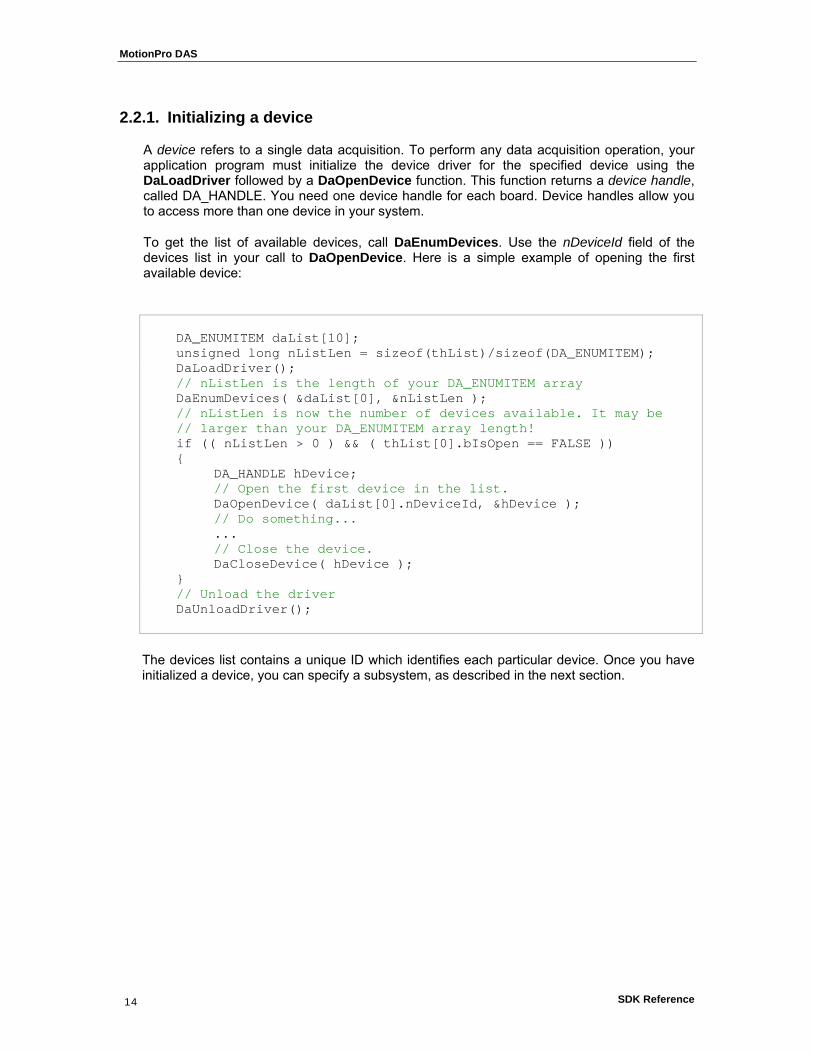
2.2.1. Initializing a device
A device refers to a single data acquisition. To perform any data acquisition operation, your application program must initialize the device driver for the specified device using the DaLoadDriver followed by a DaOpenDevice function. This function returns a device handle, called DA_HANDLE. You need one device handle for each board. Device handles allow you to access more than one device in your system.
To get the list of available devices, call DaEnumDevices. Use the nDeviceId field of the devices list in your call to DaOpenDevice. Here is a simple example of opening the first available device:
DA_ENUMITEM daList[10]; unsigned long nListLen = sizeof(thList)/sizeof(DA_ENUMITEM); DaLoadDriver(); // nListLen is the length of your DA_ENUMITEM array DaEnumDevices( &daList[0], &nListLen ); // nListLen is now the number of devices available. It may be // larger than your DA_ENUMITEM array length! if (( nListLen > 0 ) && ( thList[0].bIsOpen == FALSE )) { DA_HANDLE hDevice; // Open the first device in the list. DaOpenDevice( daList[0].nDeviceId, &hDevice ); // Do something... ... // Close the device. DaCloseDevice( hDevice ); } // Unload the driver DaUnloadDriver();
The devices list contains a unique ID which identifies each particular device. Once you have initialized a device, you can specify a subsystem, as described in the next section.

MotionPro DAS
SDK Reference 15
2.2.2. Specifying a Subsystem
A subsystem refers to the major circuitry on a device. The Data Acquisition SDK defines the following subsystems:
• Analog input (ADC subsystem),
• Analog output (DAC subsystem),
• Digital input (DIN subsystem),
• Digital output (DOUT subsystem),
Once you have initialized the device driver for the specified board, you must open the subsystem/element on the specified device using the DaOpenSubSystem function. After that you can access a subsystem specifying in subsequent functions the device handle and the subsystem ID. The subsystem IDs are reported on XsdaApi.h.
This way allows you to access more than one subsystem on a device. Once you have specified a subsystem/element, you can configure the subsystem and perform a data acquisition operation, as described in the following section.

MotionPro DAS
SDK Reference 16
2.2.3. Configuring a Subsystem
You configure a subsystem by setting its parameters. The device state is represented by an internal structure. Parameters are read and written to the internal structure with functions DaGetParameter and DaSetParameter. The function DaGetParameterAttribute provides information on a parameter's range and whether the parameter is read-only or not. When all needed parameters have been changed in the driver, you can download the new configuration set to the device and activate the new settings by calling the DaRefreshSettings function. Here is an example of setting sample rate to 10000 Hz, which means to set the clock period of the ADC subsystem to 100 microseconds.
// Set sample rate to 10000 Hz, that is period to 100 microsec DaSetParameter( hDevice,DA_SUBS_ADC,DAP_CLOCK_PERIOD,0, HZ_TO_US(10000) ); // Send settings to the device DaRefreshSettings( hDevice, DA_SUBS_ADC );
The macro HZ_TO_US can be used to transform the sample rate (in Hertz) to corresponding clock period (in microseconds).
MotionPro DAS
SDK Reference 17
2.2.4. Handling Errors
An error code is returned by each function in the SDK. An error code of 0 indicates that the function executed successfully (no error). Any other error code indicates that an error occurred. Your application program should check the value returned by each function and perform the appropriate action if an error occurs. Refer to the “Appendix A” for a list of returned error codes.
2.2.5. Handling Messages
The data acquisition board notifies your application of buffer movement and other events by generating messages. Specify the window to receive messages using the DaSetNotificationWndHandle function or the procedure to handle these messages using the DaSetNotificationProcedure function.
2.2.6. Releasing the Subsystem and the Driver
When you are finished performing data acquisition operations, release the simultaneous start list, if used, using the DaSSReleaseList function. Then, release close subsystem using the DaCloseSubSystem function. Release the driver and terminate the session using the DaCloseDevice and DaUnloadDriver function.
MotionPro DAS
SDK Reference 18
22..33.. AAnnaalloogg II//OO OOppeerraattiioonnss
The Data Acquisition SDK defines the following capabilities that you can query and/or specify for analog I/O operations:
• Channels (including channel type, channel list).
• Gains.
• Data flow modes.
• Triggered scan mode.
• Clock sources.
• Trigger sources.
• Buffers.
The following subsections describe these capabilities in more detail.

MotionPro DAS
SDK Reference 19
2.3.1. Channels
Each subsystem can have multiple channels. The Data Acquisition has 16 Analog Input channels, and 4 Analog Output channels.
2.3.1.1. Specifying a Single Channel
The simplest way to acquire data from or output data to a single channel is to specify the channel for a single-value operation. You can also specify a single channel using a channel list, described in the next section.
2.3.1.2. Specifying One or More Channels
You acquire data from or output data to one or more channels using a channel list.
The SDK allows you to group the channels in the list sequentially (either starting with 0 or with any other analog input channel) or randomly. In addition, the Data Acquisition SDK allows you to specify a single channel or the same channel more than once in the list.
Using software, specify the channels in the order you want to sample them. You can enter up to 1,024 entries in the channel-gain list. The channels are read in order (using continuously paced scan mode or triggered scan mode) from the first entry in the list to the last entry in the list.
Note: The rate at which the module can read the analog input channels depends on the total number of analog input channels in the list, and whether or not you are reading the digital input port.
The following subsections describe how to specify channels in a channel list.
Specify the channel list size: use the DaSetChannelListSize function to specify the size of the channel list.
Specify the channels in the channel List: use the DaSetParameter function to specify the channels in the channel list in the order you want to sample them or output data from them.
The channels are sampled or output in order from the first entry to the last entry in the channel list. Channel numbering is zero-based; that is, the first entry in the channel list is entry 0, the second entry is entry 1, and so on.
You can read the digital input port (all 16 digital input lines) using the analog input channel-gain list. This feature is particularly useful when you want to correlate the timing of analog and digital events. To read the digital input port, specify channel 16 in the analog input channel-gain list. You can enter channel 16 anywhere in the list, and you can enter it more than once, if desired.

MotionPro DAS
SDK Reference 20
2.3.2. Gains
The range divided by the gain determines the effective range for the entry in the channel list. For example, the Data Acquisition provides a range of ±10 V. If you want to measure a ±1.5 V signal, specify a gain of 4; the effective input range for this channel is then ±2.5 V (10/4), which provides the best sampling accuracy for that channel.
Specify the Gain for a Single Channel: the simplest way to specify gain for a single channel is to specify the gain in a single-value operation. You can also specify the gain for a single channel using a gain list, described in the next section.
Specify the Gain for One or More Channel: you can specify the gain for one or more channels using a gain list. The gain list parallels the channel list. The two lists together are often referred to as the channel-gain list or CGL.
In the Data Acquisition only the Analog Input subsystem supports programmable gain and accepts the value listed below:
// Gain typedef enum { DA_GAIN_1X = 0, DA_GAIN_2X = 1, DA_GAIN_4X = 2, DA_GAIN_8X = 3, } DA_GAIN;
Specify the gain for each entry in the channel list using the DaSetGainListEntry function.
For channel 16 (the digital input port) specify a gain of 1X.

MotionPro DAS
SDK Reference 21
2.3.3. Data Flow Mode
The Data Acquisition SDK defines the following data flow modes for ADC and DAC subsystems:
• Single value.
• Continuous.
The following subsections describe these data flow modes in detail.
2.3.3.1. Single-Value Operations
Single-value operations are the simplest to use but offer the least flexibility and efficiency. In a single-value operation, a single data value is read or written at a time. The data is returned immediately.
Use the DaGetSingleValue function to acquire a single value from an analog or digital input channel. You specify the channel and gain, and then the board acquires the data from the specified channel and returns the data immediately, in counts. Later you may want to convert the count value to volts.
To output a single value to an analog or digital output channel, use the DaPutSingleValue function. You specify the channel and value, and the board outputs the single value to the specified analog or digital channel immediately.
For a single-value operation, you cannot specify a channel-gain list, clock source, trigger source, or buffer. Single-value operations stop automatically when finished; you cannot stop a single-value operation manually.
MotionPro DAS
SDK Reference 22
2.3.3.2. Continuous Operations
For a continuous operation, you can specify any supported subsystem capability, including a channel-gain list, clock source, trigger source, pre-trigger source, retrigger source and buffer.
Call the DaStart function to start a continuous operation. To stop a continuous operation, perform either an orderly stop using the DaStop function or an abrupt stop using the DaAbort or DaReset function.
In an orderly stop (DaStop), the board finishes acquiring the specified number of samples, stops all subsequent acquisition, and transfers the acquired data to a buffer on the done queue; all subsequent triggers or retriggers are ignored.
In an abrupt stop (DaAbort), the board stops acquiring samples immediately; the acquired data is transferred to a buffer and put on the done queue; however, the buffer may not be completely filled. All subsequent triggers or retriggers are ignored.
The DaReset function reinitializes the subsystem after stopping it abruptly.
Note: For analog output operations, you can also stop the operation by not sending new data to the board. The operation stops when no more data is available.
The Data Acquisition SDK supports the following continuous modes: continuous (post-trigger), continuous pre-trigger, and continuous about-trigger.
2.3.3.3. Continuous (Post-Trigger) Mode
Use continuous (post-trigger) when you want to acquire or output data continuously when a trigger occurs. For continuous (post-trigger) mode, specify the operation mode as DA_DF_CONTINUOUS using the SetParameter (DAP_DATA_FLOW).
Use the SetParameter (DAP_TRIG_SOURCE) function to specify the trigger source that starts the operation.
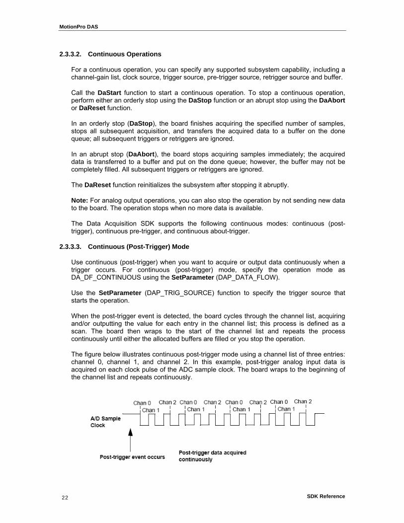
When the post-trigger event is detected, the board cycles through the channel list, acquiring and/or outputting the value for each entry in the channel list; this process is defined as a scan. The board then wraps to the start of the channel list and repeats the process continuously until either the allocated buffers are filled or you stop the operation.
The figure below illustrates continuous post-trigger mode using a channel list of three entries: channel 0, channel 1, and channel 2. In this example, post-trigger analog input data is acquired on each clock pulse of the ADC sample clock. The board wraps to the beginning of the channel list and repeats continuously.
MotionPro DAS
SDK Reference 23
2.3.4. Triggered Scan Mode
In triggered scan mode, the board scans the entries in a channel-gain list a specified number of times when it detects the specified trigger source, acquiring the data for each entry that is scanned. The Analog Input subsystem supports triggered scan mode. Triggered scan mode cannot be used with single-value operations.
If you want to enable (or disable) the triggered scan mode, call the SetParameter (DAP_TRIG_SCAN) function.
The maximum number of times that the board can scan the channel-gain list per trigger is 256. Use the SetParameter (DAP_MULTISCAN_COUNT) function to specify the number of times to scan the channel-gain list per trigger.
The Data Acquisition SDK defines the following retrigger modes for a triggered scan; these retrigger modes are described in the following subsections:
• Scan-per-trigger.
• Internal retrigger.
• Retrigger extra.
2.3.4.1. Scan-Per-Trigger Mode
Use scan-per-trigger mode if you want to accurately control the period between conversions of individual channels and retrigger the scan based on an internal or external event. In this mode, the retrigger source is the same as the initial trigger source.
The Analog Input subsystem supports scan-per-trigger mode. Specify the retrigger mode as scan-per-trigger using the SetParameter (DAP_RETRIG_MODE) function.
When it detects an initial trigger (post-trigger source only), the board scans the channel-gain list a specified number of times (determined by the SetParameter (DAP_MULTISCAN_COUNT function), then stops. When the external retrigger occurs, the process repeats.
The conversion rate of each channel in the scan is determined by the frequency of the ADC sample clock. The conversion rate of each scan is determined by the period between retriggers; therefore, it cannot be accurately controlled. The board ignores external triggers that occur while it is acquiring data. Only retrigger events that occur when the board is waiting for a trigger are detected and acted on.
2.3.4.2. Internal Retrigger Mode
Use internal retrigger mode if you want to accurately control both the period between conversions of individual channels in a scan and the period between each scan.
The Analog Input subsystem supports internal retrigger mode. Specify the retrigger mode as internal using the SetParameter (DAP_RETRIG_MODE) function. The conversion rate of each channel in the scan is determined by the frequency of the ADC sample clock. The conversion rate between scans is determined by the frequency of the internal retrigger clock on the board. You specify the period (inverse of frequency) on the internal retrigger clock using the SetParameter (DAP_RETRIG_PERIOD) function.

MotionPro DAS
SDK Reference 24
When it detects an initial trigger (pre-trigger source or post-trigger source), the board scans the channel-gain list a specified number of times (determined by the SetParameter DAP_MULTISCAN_COUNT function), then stops. When the internal retrigger occurs, determined by the frequency of the internal retrigger clock, the process repeats.
It is recommended that you set the retrigger frequency as follows:
Tmin [µs] = ( Ncgl x Ncpt ) / F + 2
Fmax [Hz] = 1.000.000 / Tmin
Where
Tmin = minimum retrigger period.
Fmax = maximum retrigger frequency (inverse of Tmin).
Ncgl = number of entries in the channel/gain list
Ncpt = number of lists per trigger.
F = ADC sampling frequency
For example, if you are using 512 channels in the channel-gain list (CGL), scanning the channel-gain list 256 times every trigger or retrigger, and using an ADC sample clock with a frequency of 1 MHz, the maximum retrigger frequency will be 7.62 Hz.

MotionPro DAS
SDK Reference 25
2.3.4.3. Retrigger Extra Mode
Use retrigger extra mode if you want to accurately control the period between conversions of individual channels and retrigger the scan on a specified retrigger source; the retrigger source can be any of the supported trigger sources.
The Analog Input subsystem supports retrigger extra mode. Specify the retrigger mode as retrigger extra using the SetParameter (DAP_RETRIG_MODE) function.
Use the SetParameter (DAP_RETRIG_SOURCE) function to specify the retrigger source. The conversion rate of each channel in the scan is determined by the frequency of the ADC sample clock. The conversion rate of each scan is determined by the period between retriggers. If you are using an internal retrigger, specify the period between retriggers using SetParameter (DAP_RETRIG_PERIOD) If you are using an external retrigger, the period between retriggers cannot be accurately controlled. The board ignores external triggers that occur while it is acquiring data. Only retrigger events that occur when the board is waiting for a trigger are detected and acted on.
MotionPro DAS
SDK Reference 26
2.3.5. Clock Sources
The Data Acquisition SDK defines internal and external clock sources, described in the following subsections. Note that you cannot specify a clock source for single-value operations.
2.3.5.1. Internal Clock Source
The internal clock is the clock source on the board that paces data acquisition or output for each entry in the channel-gain list.
Specify the clock source as internal using the SetParameter (DAP_CLOCK_SOURCE) function. Then, use the SetParameter (DAP_CLOCK_PERIOD) function to specify the period (inverse of frequency) at which to pace the operation. The maximum frequency that the Analog Input and Output subsystem supports is 500 KSamples/s (that is a period of 2 microseconds) and the minimum frequency supported is 0.75 Samples/Sec.
Note: According to sampling theory (Nyquist Theorem), you should specify a frequency for an ADC signal that is at least twice as fast as the input’s highest frequency component. For example, to accurately sample a 20 kHz signal, specify a sampling frequency of at least 40 kHz. Doing so avoids an error condition called aliasing, in which high frequency input components erroneously appear as lower frequencies after sampling.
2.3.5.2. External Clock Source
The external clock is a clock source attached to the board that paces data acquisition or output for each entry in the channel-gain list. This clock source is useful when you want to pace at rates not available with the internal clock or if you want to pace at uneven intervals.
Connect an external ADC clock to the External ADC Clock input signal on the module. Conversions start on the falling edge of the external ADC clock input signal.
Using software, specify the clock source as external using the SetParameter (DAP_CLOCK_SOURCE). The clock frequency is always equal to the frequency of the external ADC sample clock input signal that you connect to the module.
Note: if you specify channel 16 (the digital input port) in the channel-gain list, the input sample clock (internal or external) also paces the acquisition of the digital input port channels.

MotionPro DAS
SDK Reference 27
2.3.6. Trigger Sources
The Data Acquisition SDK defines the following trigger sources:
• Software (internal) trigger.
• External digital trigger edge-hi (TTL).
• External analog threshold (positive) trigger.
• External digital trigger edge-hi (TTL).
To specify a trigger source, use the SetParameter (DAP_TRIG_SOURCE) function. To specify a retrigger source, use the SetParameter (DAP_RETRIG_SOURCE) function. The following subsections describe these trigger sources. Note that you cannot specify a trigger source for single-value operations.
Software (Internal) Trigger Source: a software trigger occurs when you start the operation; internally, the computer writes to the board to begin the operation.
External Digital Trigger Edge-High (TTL) Source: an external digital trigger is a digital (TTL) signal attached to the device. The trigger occurs on the low to high transition of the external signal.
External Digital Trigger Edge-Low (TTL) Source: an external digital trigger is a digital (TTL) signal attached to the device. The trigger occurs on the high to low transition of the external signal. Only Analog Input subsystem supports this trigger source.
2.3.6.1. External Analog Threshold (positive) Trigger Source
An external analog threshold (positive) trigger is generally either an analog signal from an analog input channel or an external analog signal attached to the device. An analog trigger occurs when the device detects a transition from a negative to positive value that crosses a threshold value. The threshold level is set using SetParameter (DAP_THRESHOLD_LEVEL) to a value between 0 and 255. Setting 0 means the threshold is 0 Volt, setting 255 means the threshold is 10 Volt. Every step is 10 Volt / 256 = 0.04 Volt. For example to set a threshold of 2 Volt you should set a value of 2*256/10 = 51.

MotionPro DAS
SDK Reference 28
2.3.7. Buffers
The buffering capability applies to ADC and DAC subsystems only. Note that you cannot use a buffer with single-value operations. A data buffer is a memory location that you allocate in host memory. This memory location is used to store data for continuous input and output operations. Buffers are stored on one of three queues: the ready queue, the in-process queue, or the done queue. These queues are described in more detail in the following subsections.
2.3.7.1. Ready Queue
For input operations, the ready queue holds buffers that are empty and ready for input. For output operations, the ready queue holds buffers that you have filled with data and that are ready for output.
Allocate the buffers using the DaDataAllocBuffer function. DaDataAllocBuffer allocates a buffer of samples, where each sample is 2 bytes.
For analog input operations, it is recommended that you allocate a minimum of three buffers; for analog output operations, you can allocate one or more buffers. The size of the buffers should be at least as large as the sampling or output rate; for example, if you are using a sampling rate of 100 KSamples/s (100 kHz), specify a buffer size of 100,000 samples.
Once you have allocated the buffers (and, for output operations, filled them with data), put the buffers on the ready queue using the DaPutBuffer function.
For example, assume that you are performing an analog input operation, that you allocated three buffers, and that you put these buffers on the ready queue. The queues appear on the ready queue as shown below.
2.3.7.2. In-process Queue
When you start a continuous (post-trigger or pre-trigger) operation, the data acquisition board takes the first available buffer from the ready queue and places it on the inprocess queue.
The in-process queue holds the buffer that the specified data acquisition board is currently filling (for input operations) or outputting (for output operations). The buffer is filled or emptied at the specified clock rate.

MotionPro DAS
SDK Reference 29
Continuing with the previous example, when you start the analog input operation, the driver takes the first available buffer (Buffer 1, in this case), puts it on the inprocess queue, and starts filling it with data. The queues appear as shown below.
If you want to transfer data from a partially-filled buffer, you can use the DaFlushFromBufferInprocess function to transfer data from the buffer on an in-process queue to a buffer you create, if this capability is supported. Typically, you would use this function when your data acquisition operation is running slowly.
Only the Analog Input subsystem supports transferring data from a buffer on the in-process queue.
2.3.7.3. Done Queue
Once the data acquisition board has filled the buffer (for input operations) or emptied the buffer (for output operations), the buffer is moved from the inprocess queue to the done queue. Then, either the DA_WM_BUFFER_DONE message is generated when the buffer contains post-trigger data, or in the case of pre-trigger acquisitions, an DA_WM_PRETRIGGER_BUFFER_DONE message is generated when the buffer contains pre-trigger data.
Note: For pre-trigger acquisitions only, when the operation completes or you stop a pre-trigger acquisition, the DA_WM_QUEUE_STOPPED message is also generated.
Continuing with the previous example, the queues appear as shown in the figure below when you get the first DA_WM_BUFFER_DONE message.
MotionPro DAS
SDK Reference 30
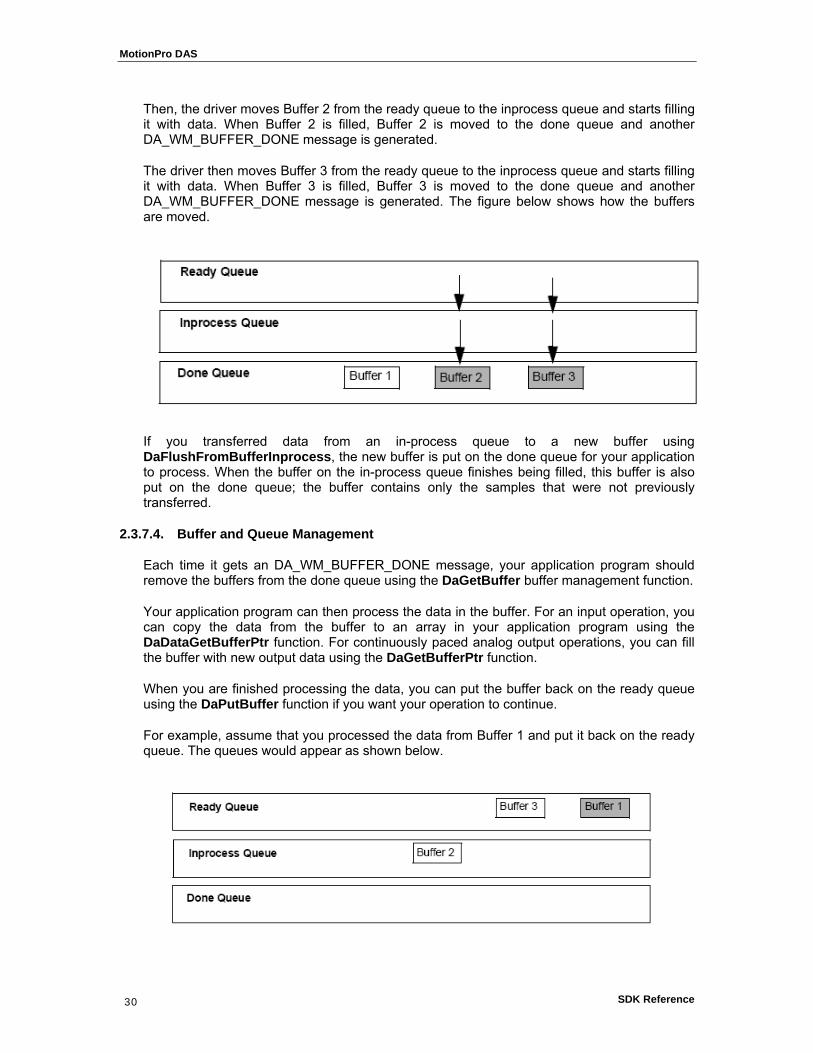
Then, the driver moves Buffer 2 from the ready queue to the inprocess queue and starts filling it with data. When Buffer 2 is filled, Buffer 2 is moved to the done queue and another DA_WM_BUFFER_DONE message is generated.
The driver then moves Buffer 3 from the ready queue to the inprocess queue and starts filling it with data. When Buffer 3 is filled, Buffer 3 is moved to the done queue and another DA_WM_BUFFER_DONE message is generated. The figure below shows how the buffers are moved.
If you transferred data from an in-process queue to a new buffer using DaFlushFromBufferInprocess, the new buffer is put on the done queue for your application to process. When the buffer on the in-process queue finishes being filled, this buffer is also put on the done queue; the buffer contains only the samples that were not previously transferred.
2.3.7.4. Buffer and Queue Management
Each time it gets an DA_WM_BUFFER_DONE message, your application program should remove the buffers from the done queue using the DaGetBuffer buffer management function.
Your application program can then process the data in the buffer. For an input operation, you can copy the data from the buffer to an array in your application program using the DaDataGetBufferPtr function. For continuously paced analog output operations, you can fill the buffer with new output data using the DaGetBufferPtr function.
When you are finished processing the data, you can put the buffer back on the ready queue using the DaPutBuffer function if you want your operation to continue.
For example, assume that you processed the data from Buffer 1 and put it back on the ready queue. The queues would appear as shown below.
MotionPro DAS
SDK Reference 31
When the data acquisition operation is finished, use the DaFlushBuffers function to transfer any data buffers left on the subsystem’s ready queue to the done queue.
Once you have processed the data in the buffers, remove the buffers from the done queue using the DaFreeBuffer function.
2.3.7.5. Buffer Wrap Modes
The Data acquisition modules can provide gap-free data, meaning no samples are missed when data is acquired or output. You can acquire gap-free data by manipulating data buffers so that no gaps exist between the last sample of the current buffer and the first sample of the next buffer.
Note: The number of buffers and buffer size are critical to the board’s ability to provide gap-free data. It is also critical that the application process the data in a timely fashion.
If you want to acquire gap-free input data, it is recommended that you specify a buffer wrap mode of none using the SetParameter (DAP_WRAP_MODE) buffer management function. When a buffer wrap mode of none is selected, if you process the buffers and put them back on the ready queue in a timely manner, the operation continues indefinitely. When no buffers are available on the ready queue, the operation stops, and an DA_WM_QUEUE_DONE message is generated.
If you want to continuously reuse the buffers in the queues and you are not concerned with gap-free data, specify multiple buffer wrap mode using SetParameter (DAP_WRAP_MODE). When multiple wrap mode is selected and no buffers are available on the ready queue, the driver moves the oldest buffer from the done queue to the in-process queue (regardless of whether you have processed its data), and overwrites the data in the buffer. This process continues indefinitely unless you stop it. When it reuses a buffer on the done queue, the driver generates a DA_WM_BUFFER_REUSED message.
If you want to perform gap-free waveform generation analog output operations, specify single wrap mode using SetParameter (DAP_WRAP_MODE). When single wrap mode is specified, a single buffer is reused continuously. In this case, the driver moves the buffer from the ready queue to the in-process queue and outputs the data from the buffer. However, when the buffer is emptied, the driver (or board) reuses the data and continuously outputs it. This process repeats indefinitely until you stop it. When you stop the operation, the buffer is moved to the done queue. No messages are posted in this mode until you stop the operation.
MotionPro DAS
SDK Reference 32
2.3.8. Simultaneous I/O Operations
If supported, you can synchronize subsystems to perform simultaneous operations. Note that you cannot perform simultaneous operations on subsystems configured for single-value operations.
You can synchronize the triggers of subsystems by specifying the same trigger source for each of the subsystems that you want to start simultaneously and wiring them to the device, if appropriate.
Use the DaSSGetList function to allocate a simultaneous start list. Then, use the DaSSAddSubSystem function to put the subsystems that you want to start simultaneously on the start list.
Pre-start the subsystems using the DaSSPreStart function. Pre-starting a subsystem ensures a minimal delay once the subsystems are started. Once you call the DaSSPreStart function, do not alter the settings of the subsystems on the simultaneous start list.
Start the subsystems using the DaSSStart function. When started, both subsystems are triggered simultaneously.
Note: Do not call DaSSStart when using simultaneous start lists, since the subsystems are already started.
When you are finished, call the DaSSReleaseList function to free the simultaneous start list. Then, call the DaCloseSubSystem function for each subsystem to free it before calling DaCloseDevice and DaUnloadDriver.
To stop the simultaneous operations, call DaStop (for an orderly stop), DaAbort (for an abrupt stop) or DaReset (for an abrupt stop that reinitializes the subsystem).
MotionPro DAS
SDK Reference 33
2.3.9. Synchronous Digital I/O operations
The user can set up a synchronous digital I/O list; this feature is useful if you want to write a digital output value to dynamic digital output channels when an analog input channel is sampled.
Use the DAP_SDIO parameter to enable or disable synchronous (dynamic) digital output operation for a specified subsystem. Once you enable a synchronous digital output operation, specify the values to write to the synchronous (dynamic) digital output channels using the DAP_SDIO_LIST function for each entry in the channel list.
To determine the maximum digital output value that you can specify, use the GetParameterAttribute function, specifying the DAP_SDIO parameter.
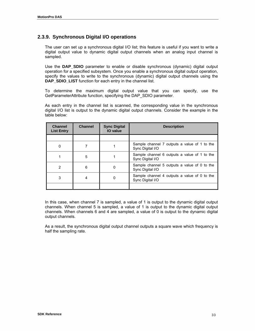
As each entry in the channel list is scanned, the corresponding value in the synchronous digital I/O list is output to the dynamic digital output channels. Consider the example in the table below:
Channel List Entry
Channel Sync Digital IO value
Description
0 7 1 Sample channel 7 outputs a value of 1 to the Sync Digital I/O
1 5 1 Sample channel 6 outputs a value of 1 to the Sync Digital I/O
2 6 0 Sample channel 5 outputs a value of 0 to the Sync Digital I/O
3 4 0 Sample channel 4 outputs a value of 0 to the Sync Digital I/O
In this case, when channel 7 is sampled, a value of 1 is output to the dynamic digital output channels. When channel 5 is sampled, a value of 1 is output to the dynamic digital output channels. When channels 6 and 4 are sampled, a value of 0 is output to the dynamic digital output channels.
As a result, the synchronous digital output channel outputs a square wave which frequency is half the sampling rate.
MotionPro DAS
SDK Reference 34
33.. DDaattaa AAccqquuiissiittiioonn SSDDKK RReeffeerreennccee
33..11.. IInniittiiaalliizzaattiioonn FFuunnccttiioonnss
3.1.1. Overview: Initialization functions
Initialization functions allow the user to initialize the Data Acquisition, enumerate the available devices, open and close them.
DaGetVersion returns the DLL version numbers and the demo flag.
DaLoadDriver loads the driver and initializes it.
DaUnloadDriver unloads the driver.
DaEnumDevices enumerates the Data Acquisition device connected to the computer.
DaOpenDevice opens a data acquisition device.
DaCloseDevice closes a data acquisition device previously open.
DaOpenSubSystem opens a data acquisition subsystem.
DaCloseSubSystem closes a data acquisition subsystem previously open.

MotionPro DAS
SDK Reference 35
3.1.2. DaGetVersion
DA_ERROR DaGetVersion (unsigned short *pVerMajor, unsigned short *pVerMinor, unsigned short *pIsDemo)
Return values
DA_SUCCESS if successful, otherwise
DA_E_GENERIC_ERROR if the version numbers could not be extracted from the driver.
Parameters
pVerMajor
Specifies the pointer to the variable that receives the major version number
pVerMinor
Specifies the pointer to the variable that receives the minor version number
pIsDemo
Specifies the pointer to the variable that receives the demo flag; If 1, the driver is demo, if 0 it isn't.
Remarks
This function must be called to retrieve the Data Acquisition DLL version number and demo flag. If the demo flag is returned TRUE, the currently installed driver does not require the presence of the device to operate.
See also:

MotionPro DAS
SDK Reference 36
3.1.3. DaLoadDriver
DA_ERROR DaLoadDriver (void)
Return values
DA_SUCCESS if successful, otherwise
DA_E_HARDWARE_FAULT if any error occurs during the initialization.
Parameters
None
Remarks
The routine loads the Data Acquisition driver DLL and initializes it. It must be called before any other routine, except DaGetVersion. If any error occurs, the routine returns DA_E_HARDWARE_FAULT. The user may retrieve the hardware error code by calling the DaGetHardwareError routine.
See also: DaUnloadDriver, DaGetHardwareError

MotionPro DAS
SDK Reference 37
3.1.4. DaUnloadDriver
void DaUnloadDriver (void)
Return values
None
Parameters
None
Remarks
This function must be called before terminating the application. This function frees any memory and resource allocated by the device driver and unloads it.
See also: DaLoadDriver
MotionPro DAS
SDK Reference 38
3.1.5. DaEnumDevices
DA_ERROR DaEnumDevices (PDA_ENUMITEM pItemList, unsigned long *pItemNr)
Return values
DA_SUCCESS if successful, otherwise
DA_E_HARDWARE_FAULT if any error occurs during the devices enumeration.
DA_E_INVALID_ARGUMENTS, if any of the parameters is not valid.
Parameters
pItemList
Specifies the pointer to an array of DA_ENUMITEM structures
pItemNr
Specifies the pointer to the variable that receives the number of detected devices
Remarks
The routine enumerates the active devices and fills the DA_ENUMITEM structures with information about them. This routine must be called before DaOpenDevice to find out which devices are available. The pItemNr variable must specify the number of structures in the pItemList array and receives the number of detected devices. If any error occurs during the devices enumeration, the routine returns DA_E_HARDWARE_FAULT. The user may retrieve the hardware error code by calling the DaGetHardwareError routine.
See also: DaOpenDevice, DaGetHardwareError
MotionPro DAS
SDK Reference 39
3.1.6. DaOpenDevice
DA_ERROR DaOpenDevice (unsigned long nDeviceId, DA_HANDLE* pHandle)
Return values
DA_SUCCESS if successful, otherwise
DA_E_INVALID_DEV_ID, if the device ID is not valid.
DA_E_ALREADY_OPEN, if the device is already open.
DA_E_HARDWARE_FAULT if any error occurs during the device opening.
Parameters
nDeviceId
Specifies the ID of the device to be opened
pHandle
Specifies the pointer to the variable that receives the device handle
Remarks
The routine opens the device whose ID is in the variable nDeviceId. The value can be retrieved calling the DaEnumDevices (see the DA_ENUMITEM structure). If any error occurs during the device opening, the routine returns DA_E_HARDWARE_FAULT. The user may retrieve the hardware error code by calling the DaGetHardwareError routine
See also: DaCloseDevice, DaGetHardwareError

MotionPro DAS
SDK Reference 40
3.1.7. DaCloseDevice
DA_ERROR DaCloseDevice (DA_HANDLE hDevice)
Return values
DA_SUCCESS if successful, otherwise
DA_E_INVALID_HANDLE, invalid device handle.
Parameters
hDevice
Specifies the handle to an open device
Remarks
Closes an open Device
See also: DaOpenDevice

MotionPro DAS
SDK Reference 41
3.1.8. DaOpenSubSystem
DA_ERROR DaOpenSubSystem (unsigned long nDeviceId, unsigned long nSubSystem)
Return values
DA_SUCCESS if successful, otherwise
DA_E_INVALID_HANDLE, if the device handle is not valid.
DA_E_INVALID_ARGUMENT, if the subsystem ID is not valid.
DA_E_HARDWARE_FAULT if any error occurs during the subsystem opening.
Parameters
nDeviceId
Specifies the ID of the device
nSubSystem
Specifies the ID of the subsystem to be opened
Remarks
The routine opens the subsystem whose ID is in the variable nSubSystem. This function required also a valid nDeviceId obtained with a call to DaOpenDevice. If any error occurs during the subsystem opening, the routine returns DA_E_HARDWARE_FAULT. The user may retrieve the hardware error code by calling the DaGetHardwareError routine
See also: DaCloseSubSystem, DaGetHardwareError

MotionPro DAS
SDK Reference 42
3.1.9. DaCloseSubSystem
DA_ERROR DaCloseSubSystem (DA_HANDLE hDevice, unsigned long nSubSystem)
Return values
DA_SUCCESS if successful, otherwise
DA_E_INVALID_HANDLE, if the device handle is not valid.
DA_E_INVALID_ARGUMENT, if the subsystem ID is not valid.
Parameters
hDevice
Specifies the handle to an open device
nSubSystem
Specifies the ID of an open subsystem
Remarks
Closes an open subsystem
See also: DaCloseSubsystem

MotionPro DAS
SDK Reference 43
33..22.. CCoonnffiigguurraattiioonn FFuunnccttiioonnss
3.2.1. Overview: Configuration functions
The configuration functions allow the user to control the parameters of the data acquisition device.
DaGetDeviceInfo gets information from the data acquisition device, such as model, firmware version, revision, etc.
DaRefreshSettings sends an updated internal structure to the device and refreshes the device settings.
DaSetParameter sets one of the device parameters in the internal structure.
DaGetParameter gets one of the parameters from the internal structure.
DaGetParameterAttribute gets a parameter's attribute, such as minimum value, maximum value, default value, read-only attribute.

MotionPro DAS
SDK Reference 44
3.2.2. DaGetDeviceInfo
DA_ERROR DaGetDeviceInfo (DA_HANDLE hDevice, DA_INFO nInfoKey, unsigned long *pValueLo, unsigned long *pValueHi)
Return values
DA_SUCCESS if successful, otherwise
DA_E_INVALID_HANDLE, if the device handle is not valid.
DA_E_INVALID_ARGUMENTS, if one of the arguments is not valid.
DA_E_NOT_SUPPORTED, if the nInfoKey is not supported.
Parameters
hDevice
Specifies the handle to an open device
nInfoKey
Specifies which parameter the function has to return
pValueLo
Specifies the pointer to the variable that receives the least significant long part of the value
pValueHi
Specifies the pointer to the variable that receives the most significant long part of the value
Remarks
This function returns device specific information, such as device type or version numbers, generally state-independent information. If the value range exceeds a 32 bit value, the most significant long value is filled. See the Appendix B for a list of all the available nInfoKey values.
See also: DaGetParameter

MotionPro DAS
SDK Reference 45
3.2.3. DaRefreshSettings
DA_ERROR DaRefreshSettings (DA_HANDLE hDevice, unsigned long nSubSystem)
Return values
DA_SUCCESS if successful, otherwise
DA_E_INVALID_ARGUMENT, if the subsystem ID is not valid.
DA_E_INVALID_HANDLE, if the device handle is not valid.
DA_E_HARDWARE_FAULT if any error occurs in driver.
Parameters
hDevice
Specifies the handle to an open device
nSubSystem
Specifies the subsystem ID
Remarks
This function configures the subsystem specified by nSubSystem according to any previously-set parameters. Subsystem parameter settings are not reflected in the hardware until DaRefreshSettings is called.
See also: DaGetParameter, DaSetParameter

MotionPro DAS
SDK Reference 46
3.2.4. DaSetParameter
DA_ERROR DaSetParameter (DA_HANDLE hDevice, unsigned long nSubSystem, DA_PARAM nParamKey, unsigned long nSubParamKey, unsigned long nValue)
Return values
DA_SUCCESS if successful, otherwise
DA_E_INVALID_HANDLE, if the device handle is not valid.
DA_E_INVALID_ARGUMENTS, if one of the arguments is not valid.
DA_E_NOT_SUPPORTED, if the nParamKey is not supported.
DA_E_READONLY, if the parameter is read-only and cannot be changed
DA_E_HARDWARE_FAULT if any error occurs in driver.
Parameters
hDevice
Specifies the handle to an open device
nSubSystem
Specifies the subsystem ID
nParamKey
Specifies which parameter the function sets.
nSubParamKey
Specifies which sub-parameter the function sets.
nValue
Specifies the parameter's value
Remarks
This function writes a parameter to the internal structure..
See also: DaGetParameter
MotionPro DAS
SDK Reference 47
3.2.5. DaGetParameter
DA_ERROR DaGetParameter (DA_HANDLE hDevice, unsigned long nSubSystem, DA_PARAM nParamKey, unsigned long nSubParamKey, unsigned long *pValue)
Return values
DA_SUCCESS if successful, otherwise
DA_E_INVALID_HANDLE, if the device handle is not valid.
DA_E_INVALID_ARGUMENTS, if one of the arguments is not valid.
DA_E_NOT_SUPPORTED, if the nParamKey is not supported.
DA_E_HARDWARE_FAULT if any error occurs in driver.
Parameters
hDevice
Specifies the handle to an open device
nSubSystem
Specifies the subsystem ID
nParamKey
Specifies which parameter the function sets.
nSubParamKey
Specifies which sub-parameter the function sets.
pValue
Specifies the pointer to the parameter's value
Remarks
This function reads a parameter from the internal structure.
See also: DaSetParameter

MotionPro DAS
SDK Reference 48
3.2.6. DaGetParameterAttribute
DA_ERROR DaGetParameterAttribute (DA_HANDLE hDevice, unsigned long nSubSystem, DA_PARAM nParamKey, DA_ATTRIBUTE nParamAttr, unsigned long *pValue)
Return values
DA_SUCCESS if successful, otherwise
DA_E_INVALID_HANDLE, if the device handle is not valid.
DA_E_INVALID_ARGUMENTS, if one of the arguments is not valid.
DA_E_NOT_SUPPORTED, if the nParamKey is not supported.
Parameters
hDevice
Specifies the handle to an open device
nSubSystem
Specifies the subsystem ID
nParamKey
Specifies which parameter the function returns.
nParamAttr
Specifies which attribute the function returns.
pValue
Specifies the pointer to the parameter's attribute value.
Remarks
This function reads a parameter attribute depending on the nParamAttr value. It may be: minimum value, maximum value, default value, read-only attribute (see Appendix D).
See also: DaGetParameter

MotionPro DAS
SDK Reference 49
33..33.. OOppeerraattiioonn FFuunnccttiioonnss
3.3.1. Overview
These functions allow the user to start operation on subsystems.
DaGetSingleValue reads a single input value from the specified subsystem channel.
DaSetSingleValue outputs a value on the subsystem channel specified.
DaGetBuffer retrieves a buffer from the done queue of the subsystem specified so that the buffer can be processed and/or put back on the ready queue. DaPutBuffer places the buffer specified onto the ready queue of the subsystem specified. DaGetBufferQueueSize retrieves the size of the driver queue, for the subsystem specified. The queue size indicates the number of buffers that are currently on the specified queue. DaFlushBuffers transfers all buffers on the ready and in-process queues of the subsystem specified to the done queue. DaFlushFromBufferInprocess copies all valid samples from the buffer currently in the in-process queue to a buffer. DaSetNotificationProcedure specifies the notification procedure to call when information messages are sent for the device and subsystem specified. DaSetNotificationWndHandle specifies the window handle to which information messages are sent for the subsystem specified. DaStart causes the subsystem specified to start the operation for which it was configured. DaStop causes the subsystem specified to cease its current operation and to return to the ready state. DaAbort directs the subsystem specified to stop its current operation immediately and to return to the ready state. DaReset causes the subsystem specified to immediately terminate any current operation and place itself into a known default state ready to receive new configuration information.

MotionPro DAS
SDK Reference 50
3.3.2. DaGetSingleValue
DA_ERROR DaGetSingleValue (DA_HANDLE hDevice, unsigned long nSubSystem, unsigned long nChannel, unsigned long nGain, unsigned long * pValue)
Return values
DA_SUCCESS if successful, otherwise
DA_E_INVALID_HANDLE, if the device handle is not valid.
DA_E_INVALID_ARGUMENTS, if one or mode arguments are not valid.
DA_E_HARDWARE_FAULT if any error occurs in driver.
Parameters
hDevice
Specifies the handle of an open device
nSubSystem
Specifies the subsystem ID
nChannel
The input channel to use
nGain
The gain setting of the input stage (see DA_GAIN)
pValue
Specifies the address in which to return the subsystem's input value
Remarks
The routine reads a single input value from the specified subsystem channel. If any error occurs during the operation and the routine returns DA_E_HARDWARE_FAULT, the user may retrieve the hardware error code by calling the DaGetHardwareError routine.
See also: DaPutSingleBuffer

MotionPro DAS
SDK Reference 51
3.3.3. DaPutSingleValue
DA_ERROR DaPutSingleValue (DA_HANDLE hDevice, unsigned long nSubSystem, unsigned long nChannel, unsigned long nGain, unsigned long nValue)
Return values
DA_SUCCESS if successful, otherwise
DA_E_INVALID_HANDLE, if the device handle is not valid.
DA_E_INVALID_ARGUMENTS, if one or mode arguments are not valid.
DA_E_HARDWARE_FAULT if any error occurs in driver.
Parameters
hDevice
Specifies the handle of an open device
nSubSystem
Specifies the subsystem ID
nChannel
The input channel to use
nGain
The gain setting of the output stage (only available value is DA_GAIN_1X)
nValue
Specifies the value to output to the subsystem. Note that only the least 16 significant bits are used.
Remarks
The routine outputs a value on the subsystem channel specified. If any error occurs during the operation and the routine returns DA_E_HARDWARE_FAULT, the user may retrieve the hardware error code by calling the DaGetHardwareError routine.
See also: DaGetSingleBuffer

MotionPro DAS
SDK Reference 52
3.3.4. DaGetBuffer
DA_ERROR DaGetBuffer (DA_HANDLE hDevice, unsigned long nSubSystem, PDA_HBUF phBuf)
Return values
DA_SUCCESS if successful, otherwise
DA_E_INVALID_HANDLE, if the device handle is not valid.
DA_E_INVALID_ARGUMENTS, if one or mode arguments are not valid.
DA_E_HARDWARE_FAULT if any error occurs in driver.
Parameters
hDevice
Specifies the handle of an open device
nSubSystem
Specifies the subsystem ID
phBuf
The returned buffer handle
Remarks
The routine retrieves a buffer from the done queue of the subsystem specified by nSubSystem so that the buffer can be processed and/or put back on the ready queue. If any error occurs during the operation and the routine returns DA_E_HARDWARE_FAULT, the user may retrieve the hardware error code by calling the DaGetHardwareError routine.
See also: DaPutBuffer

MotionPro DAS
SDK Reference 53
3.3.5. DaPutBuffer
DA_ERROR DaPutBuffer (DA_HANDLE hDevice, unsigned long nSubSystem, DA_HBUF hBuf)
Return values
DA_SUCCESS if successful, otherwise
DA_E_INVALID_HANDLE, if the device handle is not valid.
DA_E_INVALID_ARGUMENTS, if one or mode arguments are not valid.
DA_E_HARDWARE_FAULT if any error occurs in driver.
Parameters
hDevice
Specifies the handle of an open device
nSubSystem
Specifies the subsystem ID
hBuf
The buffer handle
Remarks
The routine places the buffer specified onto the ready queue of the subsystem specified. If any error occurs during the operation and the routine returns DA_E_HARDWARE_FAULT, the user may retrieve the hardware error code by calling the DaGetHardwareError routine.
See also: DaGetBuffer
MotionPro DAS
SDK Reference 54
3.3.6. DaGetBufferQueueSize
DA_ERROR DaGetBufferQueueSize (DA_HANDLE hDevice, unsigned long nSubSystem, unsigned long nQueue, unsigned long * pnSize)
Return values
DA_SUCCESS if successful, otherwise
DA_E_INVALID_HANDLE, if the device handle is not valid.
DA_E_INVALID_ARGUMENTS, if one or mode arguments are not valid.
DA_E_HARDWARE_FAULT if any error occurs in driver.
Parameters
hDevice
Specifies the handle of an open device
nSubSystem
Specifies the subsystem ID
nQueue
Specifies the queue to query (see DA_BUFF_QUEUE)
pnSize
The address in which to return the queue size.
Remarks
The routine retrieves the size of the driver queue, for the subsystem specified. The queue size indicates the number of buffers that are currently on the specified queue.. If any error occurs during the operation and the routine returns DA_E_HARDWARE_FAULT, the user may retrieve the hardware error code by calling the DaGetHardwareError routine.
See also: DaGetBuffer, DaPutBuffer

MotionPro DAS
SDK Reference 55
3.3.7. DaFlushBuffers
DA_ERROR DaFlushBuffers (DA_HANDLE hDevice, unsigned long nSubSystem)
Return values
DA_SUCCESS if successful, otherwise
DA_E_INVALID_HANDLE, if the device handle is not valid.
DA_E_INVALID_ARGUMENTS, if one or mode arguments are not valid.
DA_E_HARDWARE_FAULT if any error occurs in driver.
Parameters
hDevice
Specifies the handle of an open device
nSubSystem
Specifies the subsystem ID
Remarks
The routine specifies the notification procedure to call when information messages are sent for the device and subsystem specified. If any error occurs during the operation and the routine returns DA_E_HARDWARE_FAULT, the user may retrieve the hardware error code by calling the DaGetHardwareError routine.
See also: DaFlushFromBufferInprocess

MotionPro DAS
SDK Reference 56
3.3.8. DaFlushFromBufferInprocess
DA_ERROR DaFlushFromBufferInprocess (DA_HANDLE hDevice, unsigned long nSubSystem, DA_HBUF hBuf, unsigned long nSamples)
Return values
DA_SUCCESS if successful, otherwise
DA_E_INVALID_HANDLE, if the device handle is not valid.
DA_E_INVALID_ARGUMENTS, if one or mode arguments are not valid.
DA_E_HARDWARE_FAULT if any error occurs in driver.
Parameters
hDevice
Specifies the handle of an open device
nSubSystem
Specifies the subsystem ID
hBuf
Specifies the buffer handle
nSamples
Specifies the number of samples to copy
Remarks
The routine copies all valid samples, up to the number specified by nSamples, from the buffer currently in the in-process queue of the subsystem specified by nSubSystem to the buffer specified by hBuf. It also sets the logical size of the buffer hBuf to the number of samples copied (see DaDataSetValidSamples). The buffer is then immediately placed on the done queue, and an DA_WM_BUFFER_DONE message is generated.. If any error occurs during the operation and the routine returns DA_E_HARDWARE_FAULT, the user may retrieve the hardware error code by calling the DaGetHardwareError routine.
See also: DaFlushBuffers
MotionPro DAS
SDK Reference 57
3.3.9. DaSetNotificationProcedure
DA_ERROR DaSetNotificationProcedure (DA_HANDLE hDevice, unsigned long nSubSystem, DA_AsyncCallback pfnNotifyProc, LPARAM lParam)
Return values
DA_SUCCESS if successful, otherwise
DA_E_INVALID_HANDLE, if the device handle is not valid.
DA_E_INVALID_ARGUMENTS, if one or mode arguments are not valid.
DA_E_HARDWARE_FAULT if any error occurs in driver.
Parameters
hDevice
Specifies the handle of an open device.
nSubSystem
Specifies the subsystem ID.
pfnNotifyProc
Specifies the address of the notification procedure.
lParam
Specifies the user-defined parameter that is sent as part of all messages.
Remarks
The routine specifies the notification procedure to call when information messages are sent for the device and subsystem specified. If any error occurs during the operation and the routine returns DA_E_HARDWARE_FAULT, the user may retrieve the hardware error code by calling the DaGetHardwareError routine.
See also: DaSetNotificationWndHandle

MotionPro DAS
SDK Reference 58
3.3.10. DaSetNotificationWndHandle
DA_ERROR DaSetNotificationWndHandle (DA_HANDLE hDevice, unsigned long nSubSystem , HWND hWnd, LPARAM lParam)
Return values
DA_SUCCESS if successful, otherwise
DA_E_INVALID_HANDLE, if the device handle is not valid.
DA_E_INVALID_ARGUMENTS, if one or mode arguments are not valid.
DA_E_HARDWARE_FAULT if any error occurs in driver.
Parameters
hDevice
Specifies the handle of an open device.
nSubSystem
Specifies the subsystem ID.
hWnd
Specifies the handle of the window.
lParam
Specifies the user-defined parameter that is sent as part of all messages.
Remarks
The routine specifies the window handle to which information messages are sent for the device and subsystem specified. If any error occurs during the operation and the routine returns DA_E_HARDWARE_FAULT, the user may retrieve the hardware error code by calling the DaGetHardwareError routine.
See also: DaSetNotificationProcedure

MotionPro DAS
SDK Reference 59
3.3.11. DaStart
DA_ERROR DaStart (DA_HANDLE hDevice, unsigned long nSubSystem)
Return values
DA_SUCCESS if successful, otherwise
DA_E_INVALID_HANDLE, if the device handle is not valid.
DA_E_INVALID_ARGUMENTS, if one or mode arguments are not valid.
DA_E_HARDWARE_FAULT if any error occurs in driver.
Parameters
hDevice
Specifies the handle of an open device.
nSubSystem
Specifies the subsystem ID.
Remarks
The routine causes the subsystem specified to start the operation for which it was configured. If any error occurs during the operation and the routine returns DA_E_HARDWARE_FAULT, the user may retrieve the hardware error code by calling the DaGetHardwareError routine.
See also: DaStop

MotionPro DAS
SDK Reference 60
3.3.12. DaStop
DA_ERROR DaStop (DA_HANDLE hDevice, unsigned long nSubSystem)
Return values
DA_SUCCESS if successful, otherwise
DA_E_INVALID_HANDLE, if the device handle is not valid.
DA_E_INVALID_ARGUMENTS, if one or mode arguments are not valid.
DA_E_HARDWARE_FAULT if any error occurs in driver.
Parameters
hDevice
Specifies the handle of an open device.
nSubSystem
Specifies the subsystem ID.
Remarks
The routine causes the subsystem specified to cease its current operation and to return to the ready state. If any error occurs during the operation and the routine returns DA_E_HARDWARE_FAULT, the user may retrieve the hardware error code by calling the DaGetHardwareError routine.
See also: DaStart

MotionPro DAS
SDK Reference 61
3.3.13. DaAbort
DA_ERROR DaAbort (DA_HANDLE hDevice, unsigned long nSubSystem)
Return values
DA_SUCCESS if successful, otherwise
DA_E_INVALID_HANDLE, if the device handle is not valid.
DA_E_INVALID_ARGUMENTS, if one or mode arguments are not valid.
DA_E_HARDWARE_FAULT if any error occurs in driver.
Parameters
hDevice
Specifies the handle of an open device.
nSubSystem
Specifies the subsystem ID.
Remarks
The routine directs the subsystem specified to stop its current operation immediately and to return to the ready state. If any error occurs during the operation and the routine returns DA_E_HARDWARE_FAULT, the user may retrieve the hardware error code by calling the DaGetHardwareError routine.
See also: DaReset
MotionPro DAS
SDK Reference 62
3.3.14. DaReset
DA_ERROR DaReset (DA_HANDLE hDevice, unsigned long nSubSystem)
Return values
DA_SUCCESS if successful, otherwise
DA_E_INVALID_HANDLE, if the device handle is not valid.
DA_E_INVALID_ARGUMENTS, if one or mode arguments are not valid.
DA_E_HARDWARE_FAULT if any error occurs in driver.
Parameters
hDevice
Specifies the handle of an open device.
nSubSystem
Specifies the subsystem ID.
Remarks
The routine causes the subsystem specified to immediately terminate any current operation and place itself into a known default state ready to receive new configuration information. If any error occurs during the operation and the routine returns DA_E_HARDWARE_FAULT, the user may retrieve the hardware error code by calling the DaGetHardwareError routine.
See also: DaAbort

MotionPro DAS
SDK Reference 63
33..44.. SSiimmuullttaanneeoouuss OOppeerraattiioonn FFuunnccttiioonnss
3.4.1. Overview
These functions allow the user to perform simultaneous I/O operation on subsystems.
DaSSGetList retrieves a handle to a simultaneous start list.
DaSSAddSubSystem adds the subsystem specified on the simultaneous start list specified.
DaSSPreStart pre-starts the subsystems and ensures a minimal delay once the subsystems are started.
DaSSStart simultaneously starts all subsystems on the simultaneous start list specified. When a subsystem on the list is simultaneously started, it is actually physically started.
DaSSReleaseList releases the simultaneous start list specified and relinquishes all resources associated with the list.

MotionPro DAS
SDK Reference 64
3.4.2. DaSSGetList
DA_ERROR DaSSGetList (DA_HANDLE hDevice, PDA_HBUF phSSList)
Return values
DA_SUCCESS if successful, otherwise
DA_E_INVALID_HANDLE, if the device handle is not valid.
DA_E_HARDWARE_FAULT if any error occurs in driver.
Parameters
hDevice
Specifies the handle of an open device.
phSSList
Specifies the address in which to store the resulting simultaneous start list handle.
Remarks
The routine retrieves an handle to a simultaneous start list. If any error occurs during the operation and the routine returns DA_E_HARDWARE_FAULT, the user may retrieve the hardware error code by calling the DaGetHardwareError routine.
See also: DaReleaseList

MotionPro DAS
SDK Reference 65
3.4.3. DaSSAddSubSystem
DA_ERROR DaSSAddSubSystem (DA_HANDLE hDevice, DA_HBUF hSSList, unsigned long nSubSystem)
Return values
DA_SUCCESS if successful, otherwise
DA_E_INVALID_HANDLE, if the device handle is not valid.
DA_E_HARDWARE_FAULT if any error occurs in driver.
Parameters
hDevice
Specifies the handle of an open device.
hSSList
Specifies the handle of the simultaneous start list handle.
nSubSystem
Specifies the ID of the subsystem to add.
Remarks
The routine adds the subsystem specified to a simultaneous start list. If any error occurs during the operation and the routine returns DA_E_HARDWARE_FAULT, the user may retrieve the hardware error code by calling the DaGetHardwareError routine.
See also: DaReleaseList

MotionPro DAS
SDK Reference 66
3.4.4. DaSSPreStart
DA_ERROR DaSSPreStart (DA_HANDLE hDevice, DA_HBUF hSSList)
Return values
DA_SUCCESS if successful, otherwise
DA_E_INVALID_HANDLE, if the device handle is not valid.
DA_E_HARDWARE_FAULT if any error occurs in driver.
Parameters
hDevice
Specifies the handle of an open device.
hSSList
Specifies the handle of the simultaneous start list handle.
Remarks
The routine simultaneously pre-starts (performs setup operations on) all subsystems on the specified simultaneous start list. If any error occurs during the operation and the routine returns DA_E_HARDWARE_FAULT, the user may retrieve the hardware error code by calling the DaGetHardwareError routine.
See also: DaSSStart
MotionPro DAS
SDK Reference 67
3.4.5. DaSSStart
DA_ERROR DaSSStart (DA_HANDLE hDevice, DA_HBUF hSSList)
Return values
DA_SUCCESS if successful, otherwise
DA_E_INVALID_HANDLE, if the device handle is not valid.
DA_E_HARDWARE_FAULT if any error occurs in driver.
Parameters
hDevice
Specifies the handle of an open device.
hSSList
Specifies the handle of the simultaneous start list handle.
Remarks
The routine simultaneously starts all subsystems on the simultaneous start list specified. When a subsystem on the list is simultaneously started, it is actually physically started. If any error occurs during the operation and the routine returns DA_E_HARDWARE_FAULT, the user may retrieve the hardware error code by calling the DaGetHardwareError routine.
See also: DaSSPreStart
MotionPro DAS
SDK Reference 68
3.4.6. DaSSReleaseList
DA_ERROR DaSSReleaseList (DA_HANDLE hDevice, DA_HBUF hSSList)
Return values
DA_SUCCESS if successful, otherwise
DA_E_INVALID_HANDLE, if the device handle is not valid.
DA_E_HARDWARE_FAULT if any error occurs in driver.
Parameters
hDevice
Specifies the handle of an open device.
hSSList
Specifies the handle of the simultaneous start list handle.
Remarks
The routine releases the simultaneous start list specified and relinquishes all resources associated with the list. If any error occurs during the operation and the routine returns DA_E_HARDWARE_FAULT, the user may retrieve the hardware error code by calling the DaGetHardwareError routine.
See also: DaSSGetList

MotionPro DAS
SDK Reference 69
33..55.. DDaattaa MMaannaaggeemmeenntt FFuunnccttiioonnss
3.5.1. Overview
The data Management functions, listed below, are intended for use by both application and system programmers. They provide a set of object-oriented buffer management facilities. When a buffer object is created, a buffer handle (HBUF) is returned. This handle is used in all subsequent buffer manipulation. DaDataAllocBuffer allocates a data buffer of the specified sample size.
DaDataFreeBuffer frees the buffer associated with the handle specified.
DaDataGetBufferPtr returns a data buffer pointer suitable for direct program manipulation
DaDataSetValidSamples sets the number of valid samples the buffer specified can hold
DaDataGetValidSamples returns the number of valid samples a buffer can hold
DaDataGetMaxSamples returns the maximum number of samples the specified buffer can hold.
MotionPro DAS
SDK Reference 70
3.5.2. DaDataAllocBuffer
DA_ERROR DaDataAllocBuffer (DA_HANDLE hDevice, unsigned long nSize , PDA_HBUF phBuf)
Return values
DA_SUCCESS if successful, otherwise
DA_E_INVALID_HANDLE, if the device handle is not valid.
DA_E_HARDWARE_FAULT if any error occurs in driver.
Parameters
hDevice
Specifies the handle of an open device.
nSize
Specifies the size of the buffer, in samples.
phBuf
Specifies the address in which the buffer handle is returned.
Remarks
It allocates a data buffer of the specified sample size. Note that since one sample is 16 bits the allocated buffer size will be (2 x nSize) bytes. If any error occurs during the operation and the routine returns DA_E_HARDWARE_FAULT, the user may retrieve the hardware error code by calling the DaGetHardwareError routine.
See also: DaDataFreeBuffer
MotionPro DAS
SDK Reference 71
3.5.3. DaDataFreeBuffer
DA_ERROR DaDataFreeBuffer (DA_HANDLE hDevice, DA_HBUF hBuf)
Return values
DA_SUCCESS if successful, otherwise
DA_E_INVALID_HANDLE, if the device handle is not valid.
DA_E_HARDWARE_FAULT if any error occurs in driver.
Parameters
hDevice
Specifies the handle of an open device.
hBuf
Specifies the buffer handle.
Remarks
This function deletes the buffer associated with the handle specified. If any error occurs during the operation and the routine returns DA_E_HARDWARE_FAULT, the user may retrieve the hardware error code by calling the DaGetHardwareError routine.
See also: DaDataAllocBuffer
MotionPro DAS
SDK Reference 72
3.5.4. DaDataGetBufferPtr
DA_ERROR DaDataGetBufferPtr (DA_HANDLE hDevice, DA_HBUF hBuf, LPVOID * pBuf)
Return values
DA_SUCCESS if successful, otherwise
DA_E_INVALID_HANDLE, if the device handle is not valid.
DA_E_HARDWARE_FAULT if any error occurs in driver.
Parameters
hDevice
Specifies the handle of an open device.
hBuf
Specifies the buffer handle.
pBuf
Specifies the address in which the data buffer pointer is returned.
Remarks
This function returns a data buffer pointer suitable for direct program manipulation. If any error occurs during the operation and the routine returns DA_E_HARDWARE_FAULT, the user may retrieve the hardware error code by calling the DaGetHardwareError routine.
See also: DaDataAllocBuffer

MotionPro DAS
SDK Reference 73
3.5.5. DaDataSetValidSamples
DA_ERROR DaDataSetValidSamples (DA_HANDLE hDevice, DA_HBUF hBuf, unsigned long nSamples)
Return values
DA_SUCCESS if successful, otherwise
DA_E_INVALID_HANDLE, if the device handle is not valid.
DA_E_HARDWARE_FAULT if any error occurs in driver.
Parameters
hDevice
Specifies the handle of an open device.
hBuf
Specifies the buffer handle.
nSamples
Specifies the number of valid samples.
Remarks
This function sets the number of valid samples the buffer specified can hold (always less than or equal to physical size). This value corresponds to the physical size of the buffer (in bytes) divided by the data width (2). You must call this function when the buffer is to be used for an output subsystem. If any error occurs during the operation and the routine returns DA_E_HARDWARE_FAULT, the user may retrieve the hardware error code by calling the DaGetHardwareError routine.
See also: DaDataGetValidSamples

MotionPro DAS
SDK Reference 74
3.5.6. DaDataGetValidSamples
DA_ERROR DaDataGetValidSamples (DA_HANDLE hDevice, DA_HBUF hBuf, unsigned long * pnSamples)
Return values
DA_SUCCESS if successful, otherwise
DA_E_INVALID_HANDLE, if the device handle is not valid.
DA_E_HARDWARE_FAULT if any error occurs in driver.
Parameters
hDevice
Specifies the handle of an open device.
hBuf
Specifies the buffer handle.
pnSamples
Specifies the address in which the number of valid samples is returned.
Remarks
This function returns, in pnSamples, the number of valid samples a buffer can hold (always less than or equal to the physical size). This value corresponds to the logical size of the buffer (in bytes) divided by the data width (2). You can use this function to determine the number of valid samples in an aborted buffer or to determine the number of valid samples in a buffer where an error occurred or had samples flushed from it. If any error occurs during the operation and the routine returns DA_E_HARDWARE_FAULT, the user may retrieve the hardware error code by calling the DaGetHardwareError routine.
See also: DaDataSetValidSamples
MotionPro DAS
SDK Reference 75
3.5.7. DaDataGetMaxSamples
DA_ERROR DaDataGetMaxSamples (DA_HANDLE hDevice, DA_HBUF hBuf, unsigned long * pnMax)
Return values
DA_SUCCESS if successful, otherwise
DA_E_INVALID_HANDLE, if the device handle is not valid.
DA_E_HARDWARE_FAULT if any error occurs in driver.
Parameters
hDevice
Specifies the handle of an open device.
hBuf
Specifies the buffer handle.
pnMax
Specifies the address in which the maximum number of samples is returned.
Remarks
This function returns the maximum number of samples the specified buffer can hold. This value corresponds to the physical size of the buffer (in bytes) divided by the data width (2). If any error occurs during the operation and the routine returns DA_E_HARDWARE_FAULT, the user may retrieve the hardware error code by calling the DaGetHardwareError routine.
See also: DaDataGetValidSamples

MotionPro DAS
SDK Reference 76
33..66.. MMiisscceellllaanneeoouuss FFuunnccttiioonnss
3.6.1. Overview
Miscellaneous functions allow the user to read hardware error codes and strings.
DaGetHardwareError reads the hardware error code and returns the error string related to that code.
MotionPro DAS
SDK Reference 77
3.6.2. DaGetHardwareError
DA_ERROR DaGetHardwareError (DA_HANDLE hDevice, unsigned long* pnHwError, char* pszBuffer, unsigned long nSize)
Return values
DA_SUCCESS if successful, otherwise
DA_E_INVALID_HANDLE, if the device handle is not valid.
DA_E_INVALID_ARGUMENTS, if one of the arguments is not valid.
DA_E_GENERIC_ERROR, if the hardware error code is not correct.
Parameters
hDevice
Specifies the handle to an open device
pnHwError
Specifies the pointer to the variable which receives the error code
pszBuffer
Specifies the char buffer which receives the error string
nSize
Specifies the size in bytes of the char buffer
Remarks
If any of the driver’s API returns DA_E_HARDWARE_FAULT, the hardware related error may be retrieved by calling DaGetHardwareError function. The function returns the hardware error occurred after the latest device operation. Also, the function fills the pszBuffer buffer with a message that describes the returned error code.
See also:

MotionPro DAS
SDK Reference 78
44.. DDaattaa AAccqquuiissiittiioonn AAccttiivveeXX™™ ccoonnttrrooll
44..11.. OOvveerrvviieeww
ActiveX is a set of technologies that enable software components to interact with one another in a networked environment, regardless of the language in which the components were created. An ActiveX control is a user interface element created using ActiveX technology. ActiveX controls are small, fast, and powerful, and make it easy to integrate and reuse software components.
The XsdaX ActiveX control includes all the capabilities of the Data Acquisition in a simple windowless control that can be inserted in any application. The ActiveX technology is supported in Windows™ Operating Systems only.

MotionPro DAS
SDK Reference 79
44..22.. IInniittiiaalliizzaattiioonn FFuunnccttiioonnss
4.2.1. Overview: Initialization functions
Initialization functions allow the user to initialize the Data Acquisition, enumerate the available devices, open and close them.
GetVersion returns the DLL version numbers and the demo flag.
LoadDriver loads the driver and initializes it.
UnloadDriver unloads the driver.
Enumerate enumerates the Data Acquisition devices connected to the computer.
OpenDevice opens a data acquisition device.
CloseDevice closes a data acquisition device previously open.
OpenSubSystem opens a data acquisition subsystem.
CloseSubSystem closes a data acquisition subsystem previously open.
MotionPro DAS
SDK Reference 80
4.2.2. GetVersion
long GetVersion (long pVerMajor, long pVerMinor, long pIsDemo)
Return values
DA_SUCCESS if successful, otherwise
DA_E_GENERIC_ERROR if the version numbers could not be extracted from the driver.
Parameters
pVerMajor
Specifies the pointer to the variable that receives the major version number
pVerMinor
Specifies the pointer to the variable that receives the minor version number
pIsDemo
Specifies the pointer to the variable that receives the demo flag; If 1, the driver is demo, if 0 it isn't.
Remarks
This function must be called to retrieve the Data Acquisition DLL version number and demo flag. If the demo flag is returned TRUE, the currently installed driver does not require the presence of the device to operate.
See also:
MotionPro DAS
SDK Reference 81
4.2.3. LoadDriver
long LoadDriver (void)
Return values
DA_SUCCESS if successful, otherwise
DA_E_HARDWARE_FAULT if any error occurs during the initialization.
Parameters
None
Remarks
The routine loads the Data Acquisition driver DLL and initializes it. It must be called before any other routine, except DaGetVersion. If any error occurs, the routine returns DA_E_HARDWARE_FAULT. The user may retrieve the hardware error code by calling the DaGetHardwareError routine.
See also: UnloadDriver, GetHardwareError
MotionPro DAS
SDK Reference 82
4.2.4. UnloadDriver
void UnloadDriver (void)
Return values
None
Parameters
None
Remarks
This function must be called before terminating the application. This function frees any memory and resource allocated by the device driver and unloads it.
See also: LoadDriver

MotionPro DAS
SDK Reference 83
4.2.5. Enumerate
long Enumerate (long pItemList, long pItemNr)
Return values
DA_SUCCESS if successful, otherwise
DA_E_HARDWARE_FAULT if any error occurs during the devices enumeration.
DA_E_INVALID_ARGUMENTS, if any of the parameters is not valid.
Parameters
pItemList
Specifies the pointer to an array of DA_ENUMITEM structures
pItemNr
Specifies the pointer to the variable that receives the number of detected devices
Remarks
The routine enumerates the active devices and fills the DA_ENUMITEM structures with information about them. This routine must be called before OpenDevice to find out which devices are available. The pItemNr variable must specify the number of structures in the pItemList array and receives the number of detected devices. If any error occurs during the devices enumeration, the routine returns DA_E_HARDWARE_FAULT. The user may retrieve the hardware error code by calling the GetHardwareError routine.
See also: OpenDevice, GetHardwareError

MotionPro DAS
SDK Reference 84
4.2.6. OpenDevice
long DaOpenDevice (long nDeviceId )
Return values
DA_SUCCESS if successful, otherwise
DA_E_INVALID_DEV_ID, if the device ID is not valid.
DA_E_ALREADY_OPEN, if the device is already open.
DA_E_HARDWARE_FAULT if any error occurs during the device opening.
Parameters
nDeviceId
Specifies the ID of the device to be opened
Remarks
The routine opens the device whose ID is in the variable nDeviceId. The value can be retrieved calling the Enumerate (see the DA_ENUMITEM structure). If any error occurs during the device opening, the routine returns DA_E_HARDWARE_FAULT. The user may retrieve the hardware error code by calling the GetHardwareError routine.
See also: CloseDevice, GetHardwareError

MotionPro DAS
SDK Reference 85
4.2.7. CloseDevice
long CloseDevice ( void )
Return values
DA_SUCCESS if successful, otherwise
DA_E_INVALID_HANDLE, invalid device handle.
Parameters
None
Remarks
Closes an open Device
See also: OpenDevice

MotionPro DAS
SDK Reference 86
4.2.8. OpenSubSystem
long OpenSubSystem ( long nSubSystem)
Return values
DA_SUCCESS if successful, otherwise
DA_E_INVALID_HANDLE, if the device handle is not valid.
DA_E_INVALID_ARGUMENT, if the subsystem ID is not valid.
DA_E_HARDWARE_FAULT if any error occurs during the subsystem opening.
Parameters
nSubSystem
Specifies the ID of the subsystem to be opened
Remarks
The routine opens the subsystem whose ID is in the variable nSubSystem. If any error occurs during the subsystem opening, the routine returns DA_E_HARDWARE_FAULT. The user may retrieve the hardware error code by calling the GetHardwareError routine
See also: CloseSubSystem, GetHardwareError

MotionPro DAS
SDK Reference 87
4.2.9. CloseSubSystem
long CloseSubSystem ( long nSubSystem )
Return values
DA_SUCCESS if successful, otherwise
DA_E_INVALID_HANDLE, if the device handle is not valid.
DA_E_INVALID_ARGUMENT, if the subsystem ID is not valid.
Parameters
nSubSystem
Specifies the ID of an open subsystem
Remarks
Closes an open subsystem
See also: OpenSubSystem
MotionPro DAS
SDK Reference 88
44..33.. CCoonnffiigguurraattiioonn FFuunnccttiioonnss
4.3.1. Overview: Configuration functions
The configuration functions allow the user to control the parameters of the data acquisition device.
GetDeviceInfo gets information from the data acquisition device, such as model, firmware version, revision, etc.
RefreshSettings sends an updated internal structure to the device and refreshes the device settings.
SetParameter sets one of the device parameters in the internal structure.
GetParameter gets one of the parameters from the internal structure.
GetParameterAttribute gets a parameter's attribute, such as minimum value, maximum value, default value, read-only attribute.

MotionPro DAS
SDK Reference 89
4.3.2. GetInfo
long GetInfo ( long nInfoKey, long pValueLo, long pValueHi )
Return values
DA_SUCCESS if successful, otherwise
DA_E_INVALID_HANDLE, if the device handle is not valid.
DA_E_INVALID_ARGUMENTS, if one of the arguments is not valid.
DA_E_NOT_SUPPORTED, if the nInfoKey is not supported.
Parameters
nInfoKey
Specifies which parameter the function has to return
pValueLo
Specifies the pointer to the variable that receives the least significant long part of the value
pValueHi
Specifies the pointer to the variable that receives the most significant long part of the value
Remarks
This function returns device specific information, such as device type or version numbers, generally state-independent information. If the value range exceeds a 32 bit value, the most significant long value is filled. See the Appendix B for a list of all the available nInfoKey values.
See also: GetParameter

MotionPro DAS
SDK Reference 90
4.3.3. RefreshSettings
long RefreshSettings ( long nSubSystem )
Return values
DA_SUCCESS if successful, otherwise
DA_E_INVALID_ARGUMENT, if the subsystem ID is not valid.
DA_E_INVALID_HANDLE, if the device handle is not valid.
DA_E_HARDWARE_FAULT if any error occurs in driver.
Parameters
nSubSystem
Specifies the subsystem ID
Remarks
This function configures the subsystem specified by nSubSystem according to any previously-set parameters. Subsystem parameter settings are not reflected in the hardware until RefreshSettings is called.
See also: GetParameter, SetParameter

MotionPro DAS
SDK Reference 91
4.3.4. SetParameter
long SetParameter (long nSubSystem, long nParamKey, long nSubParamKey, long nValue)
Return values
DA_SUCCESS if successful, otherwise
DA_E_INVALID_HANDLE, if the device handle is not valid.
DA_E_INVALID_ARGUMENTS, if one of the arguments is not valid.
DA_E_NOT_SUPPORTED, if the nParamKey is not supported.
DA_E_READONLY, if the parameter is read-only and cannot be changed
DA_E_HARDWARE_FAULT if any error occurs in driver.
Parameters
nSubSystem
Specifies the subsystem ID
nParamKey
Specifies which parameter the function sets.
nSubParamKey
Specifies which sub-parameter the function sets.
nValue
Specifies the parameter's value
Remarks
This function writes a parameter to the subsystem. Subsystem parameter settings are not reflected in the hardware until RefreshSettings is called.
See also: DaGetParameter, RefreshSettings
MotionPro DAS
SDK Reference 92
4.3.5. GetParameter
long GetParameter ( long nSubSystem, long nParamKey, long nSubParamKey, long pValue )
Return values
DA_SUCCESS if successful, otherwise
DA_E_INVALID_HANDLE, if the device handle is not valid.
DA_E_INVALID_ARGUMENTS, if one of the arguments is not valid.
DA_E_NOT_SUPPORTED, if the nParamKey is not supported.
DA_E_HARDWARE_FAULT if any error occurs in driver.
Parameters
nSubSystem
Specifies the subsystem ID
nParamKey
Specifies which parameter the function sets.
nSubParamKey
Specifies which sub-parameter the function sets.
pValue
Specifies the pointer to the parameter's value
Remarks
This function reads a parameter from a subsystem.
See also: SetParameter, RefreshSettings

MotionPro DAS
SDK Reference 93
4.3.6. GetParameterAttribute
long GetParameterAttribute (long nSubSystem, long nParamKey, long nParamAttr, long pValue )
Return values
DA_SUCCESS if successful, otherwise
DA_E_INVALID_HANDLE, if the device handle is not valid.
DA_E_INVALID_ARGUMENTS, if one of the arguments is not valid.
DA_E_NOT_SUPPORTED, if the nParamKey is not supported.
Parameters
nSubSystem
Specifies the subsystem ID
nParamKey
Specifies which parameter the function returns.
nParamAttr
Specifies which attribute the function returns.
pValue
Specifies the pointer to the parameter's attribute value.
Remarks
This function reads a parameter attribute depending on the nParamAttr value. It may be: minimum value, maximum value, default value, read-only attribute (see Appendix D).
See also: GetParameter

MotionPro DAS
SDK Reference 94
44..44.. OOppeerraattiioonn FFuunnccttiioonnss
4.4.1. Overview
These functions allow the user to perform I/O operation on subsystems.
GetSingleValue reads a single input value from the specified subsystem channel.
PutSingleValue outputs a value to the specified subsystem channel.
GetBuffer retrieves a buffer from the done queue of a subsystem. Then the buffer may be processed and/or put back on the ready queue.
PutBuffer places the buffer specified onto the ready queue of the specified subsystem.
GetBufferQueueSize retrieves the size of the driver queue, for the subsystem specified. The queue size indicates the number of buffers that are currently on the specified queue.
FlushBuffers transfers all buffers on the ready and in-process queues of the subsystem specified to the done queue.
FlushFromBufferInprocess copies all valid samples from the buffer currently in the in-process queue to a destination buffer. It also sets the logical size of the destination buffer to the number of samples copied.
SetNotificationProcedure specifies the notification procedure to call when information messages are sent for the device and subsystem specified.
SetNotificationWndHandle specifies the window handle to which information messages are sent for the subsystem specified.
Start causes the subsystem specified to start the operation for which it was configured.
Stop causes the subsystem specified to cease its current operation and to return to the ready state.
Abort directs the subsystem specified to stop its current operation immediately and to return to the ready state.
Reset causes the subsystem specified to immediately terminate any current operation and place itself into a known default state ready to receive new configuration information.

MotionPro DAS
SDK Reference 95
4.4.2. GetSingleValue
long GetSingleValue (long nSubSystem, long nChannel, long nGain, long pValue)
Return values
DA_SUCCESS if successful, otherwise
DA_E_INVALID_HANDLE, if the device handle is not valid.
DA_E_INVALID_ARGUMENTS, if one or mode arguments are not valid.
DA_E_HARDWARE_FAULT if any error occurs in driver.
Parameters
nSubSystem
Specifies the subsystem ID
nChannel
The input channel to use
nGain
The gain setting of the input stage (see DA_GAIN)
pValue
Specifies the address in which to return the subsystem's input value
Remarks
The routine reads a single input value from the specified subsystem channel. If any error occurs during the operation and the routine returns DA_E_HARDWARE_FAULT, the user may retrieve the hardware error code by calling the GetHardwareError routine.
See also: PutSingleValue

MotionPro DAS
SDK Reference 96
4.4.3. PutSingleValue
long PutSingleValue (long nSubSystem, long nChannel, long nGain, long nValue)
Return values
DA_SUCCESS if successful, otherwise
DA_E_INVALID_HANDLE, if the device handle is not valid.
DA_E_INVALID_ARGUMENTS, if one or mode arguments are not valid.
DA_E_HARDWARE_FAULT if any error occurs in driver.
Parameters
nSubSystem
Specifies the subsystem ID
nChannel
The input channel to use
nGain
The gain setting of the output stage (only available value is DA_GAIN_1X)
nValue
Specifies the value to output to the subsystem. Only the least 16 significant bits are used.
Remarks
The routine outputs a value to the specified subsystem channel. If any error occurs during the operation and the routine returns DA_E_HARDWARE_FAULT, the user may retrieve the hardware error code by calling the GetHardwareError routine.
See also: GetSingleValue

MotionPro DAS
SDK Reference 97
4.4.4. GetBuffer
long GetBuffer ( long nSubSystem, long phBuf )
Return values
DA_SUCCESS if successful, otherwise
DA_E_INVALID_HANDLE, if the device handle is not valid.
DA_E_INVALID_ARGUMENTS, if one or mode arguments are not valid.
DA_E_HARDWARE_FAULT if any error occurs in driver.
Parameters
nSubSystem
Specifies the subsystem ID
phBuf
The returned buffer handle
Remarks
The routine retrieves a buffer from the done queue of the subsystem specified by nSubSystem. Then the buffer may be processed and/or put back on the ready queue. If any error occurs during the operation and the routine returns DA_E_HARDWARE_FAULT, the user may retrieve the hardware error code by calling the GetHardwareError routine.
See also: PutBuffer

MotionPro DAS
SDK Reference 98
4.4.5. PutBuffer
long PutBuffer (DA_HANDLE hDevice, unsigned long nSubSystem, DA_HBUF hBuf)
Return values
DA_SUCCESS if successful, otherwise
DA_E_INVALID_HANDLE, if the device handle is not valid.
DA_E_INVALID_ARGUMENTS, if one or mode arguments are not valid.
DA_E_HARDWARE_FAULT if any error occurs in driver.
Parameters
nSubSystem
Specifies the subsystem ID
hBuf
The buffer handle
Remarks
The routine places the buffer specified onto the ready queue of the subsystem specified. If any error occurs during the operation and the routine returns DA_E_HARDWARE_FAULT, the user may retrieve the hardware error code by calling the GetHardwareError routine.
See also: GetBuffer

MotionPro DAS
SDK Reference 99
4.4.6. GetBufferQueueSize
long GetBufferQueueSize ( long nSubSystem, long nQueue, long pnSize )
Return values
DA_SUCCESS if successful, otherwise
DA_E_INVALID_HANDLE, if the device handle is not valid.
DA_E_INVALID_ARGUMENTS, if one or mode arguments are not valid.
DA_E_HARDWARE_FAULT if any error occurs in driver.
Parameters
nSubSystem
Specifies the subsystem ID
nQueue
Specifies the queue to query (see DA_BUFF_QUEUE)
pnSize
It’s the address to which to return the queue size.
Remarks
The routine retrieves the size of the driver queue, for the subsystem specified. The queue size indicates the number of buffers that are currently on the specified queue. If any error occurs during the operation and the routine returns DA_E_HARDWARE_FAULT, the user may retrieve the hardware error code by calling the GetHardwareError routine.
See also: GetBuffer, PutBuffer
MotionPro DAS
SDK Reference 100
4.4.7. FlushBuffers
long FlushBuffers (long nSubSystem)
Return values
DA_SUCCESS if successful, otherwise
DA_E_INVALID_HANDLE, if the device handle is not valid.
DA_E_INVALID_ARGUMENTS, if one or mode arguments are not valid.
DA_E_HARDWARE_FAULT if any error occurs in driver.
Parameters
nSubSystem
Specifies the subsystem ID
Remarks
This function transfers all buffers on the ready and in-process queues of the subsystem specified by nSubSystem to the done queue. If any error occurs during the operation and the routine returns DA_E_HARDWARE_FAULT, the user may retrieve the hardware error code by calling the GetHardwareError routine.
See also: FlushFromBufferInprocess
MotionPro DAS
SDK Reference 101
4.4.8. FlushFromBufferInprocess
long FlushFromBufferInprocess ( long nSubSystem, long hBuf, long nSamples )
Return values
DA_SUCCESS if successful, otherwise
DA_E_INVALID_HANDLE, if the device handle is not valid.
DA_E_INVALID_ARGUMENTS, if one or mode arguments are not valid.
DA_E_HARDWARE_FAULT if any error occurs in driver.
Parameters
nSubSystem
Specifies the subsystem ID
hBuf
Specifies the buffer handle
nSamples
Specifies the number of samples to copy
Remarks
The routine copies all valid samples, up to the number specified by nSamples, from the buffer currently in the in-process queue of the subsystem specified by nSubSystem to the buffer specified by hBuf. It also sets the logical size of the buffer hBuf to the number of samples copied (see DataSetValidSamples). The buffer is then immediately placed on the done queue, and an DA_WM_BUFFER_DONE message is generated. If any error occurs during the operation and the routine returns DA_E_HARDWARE_FAULT, the user may retrieve the hardware error code by calling the DaGetHardwareError routine.
See also: DaFlushBuffers

MotionPro DAS
SDK Reference 102
4.4.9. SetNotificationProcedure
long SetNotificationProcedure (long nSubSystem, long pfnNotifyProc, long lParam)
Return values
DA_SUCCESS if successful, otherwise
DA_E_INVALID_HANDLE, if the device handle is not valid.
DA_E_INVALID_ARGUMENTS, if one or mode arguments are not valid.
DA_E_HARDWARE_FAULT if any error occurs in driver.
Parameters
nSubSystem
Specifies the subsystem ID.
pfnNotifyProc
Specifies the address of the notification procedure.
lParam
Specifies the user-defined parameter that is sent as part of all messages.
Remarks
This function specifies the notification procedure, pfnNotifyProc, to call when information messages are sent for the subsystem specified by nSubSystem. If any error occurs during the operation and the routine returns DA_E_HARDWARE_FAULT, the user may retrieve the hardware error code by calling the GetHardwareError routine.
See also: SetNotificationWndHandle

MotionPro DAS
SDK Reference 103
4.4.10. SetNotificationWndHandle
long SetNotificationWndHandle (long nSubSystem , long hWnd, long lParam)
Return values
DA_SUCCESS if successful, otherwise
DA_E_INVALID_HANDLE, if the device handle is not valid.
DA_E_INVALID_ARGUMENTS, if one or mode arguments are not valid.
DA_E_HARDWARE_FAULT if any error occurs in driver.
Parameters
nSubSystem
Specifies the subsystem ID.
hWnd
Specifies the handle of the window.
lParam
Specifies the user-defined parameter that is sent as part of all messages.
Remarks
The routine specifies the window handle to which information messages are sent for subsystem specified by nSubSystem. If any error occurs during the operation and the routine returns DA_E_HARDWARE_FAULT, the user may retrieve the hardware error code by calling the GetHardwareError routine.
See also: SetNotificationProcedure

MotionPro DAS
SDK Reference 104
4.4.11. Start
long Start (long nSubSystem)
Return values
DA_SUCCESS if successful, otherwise
DA_E_INVALID_HANDLE, if the device handle is not valid.
DA_E_INVALID_ARGUMENTS, if one or mode arguments are not valid.
DA_E_HARDWARE_FAULT if any error occurs in driver.
Parameters
nSubSystem
Specifies the subsystem ID.
Remarks
The routine causes the subsystem specified to start the operation for which it was configured. If any error occurs during the operation and the routine returns DA_E_HARDWARE_FAULT, the user may retrieve the hardware error code by calling the GetHardwareError routine.
See also: Stop

MotionPro DAS
SDK Reference 105
4.4.12. Stop
long Stop (long nSubSystem)
Return values
DA_SUCCESS if successful, otherwise
DA_E_INVALID_HANDLE, if the device handle is not valid.
DA_E_INVALID_ARGUMENTS, if one or mode arguments are not valid.
DA_E_HARDWARE_FAULT if any error occurs in driver.
Parameters
nSubSystem
Specifies the subsystem ID.
Remarks
The routine causes the subsystem specified to cease its current operation and to return to the ready state. If any error occurs during the operation and the routine returns DA_E_HARDWARE_FAULT, the user may retrieve the hardware error code by calling the GetHardwareError routine.
See also: Start

MotionPro DAS
SDK Reference 106
4.4.13. Abort
long Abort (long nSubSystem)
Return values
DA_SUCCESS if successful, otherwise
DA_E_INVALID_HANDLE, if the device handle is not valid.
DA_E_INVALID_ARGUMENTS, if one or mode arguments are not valid.
DA_E_HARDWARE_FAULT if any error occurs in driver.
Parameters
nSubSystem
Specifies the subsystem ID.
Remarks
The routine directs the subsystem specified to stop its current operation immediately and to return to the ready state. If any error occurs during the operation and the routine returns DA_E_HARDWARE_FAULT, the user may retrieve the hardware error code by calling the GetHardwareError routine.
See also: Reset

MotionPro DAS
SDK Reference 107
4.4.14. Reset
long Reset ( long nSubSystem )
Return values
DA_SUCCESS if successful, otherwise
DA_E_INVALID_HANDLE, if the device handle is not valid.
DA_E_INVALID_ARGUMENTS, if one or mode arguments are not valid.
DA_E_HARDWARE_FAULT if any error occurs in driver.
Parameters
nSubSystem
Specifies the subsystem ID.
Remarks
The routine causes the subsystem specified to immediately terminate any current operation and place itself into a known default state ready to receive new configuration information. If any error occurs during the operation and the routine returns DA_E_HARDWARE_FAULT, the user may retrieve the hardware error code by calling the GetHardwareError routine.
See also: Abort

MotionPro DAS
SDK Reference 108
44..55.. SSiimmuullttaanneeoouuss OOppeerraattiioonn FFuunnccttiioonnss
4.5.1. Overview
These functions allow the user to perform simultaneous I/O operation on subsystems.
SSGetList retrieves a handle to a simultaneous start list.
SSAddSubSystem adds the subsystem specified on the simultaneous start list specified.
SSStart simultaneously starts all subsystems on the simultaneous start list specified. When a subsystem on the list is simultaneously started, it is actually physically started.
SSReleaseList releases the simultaneous start list specified and relinquishes all resources associated with the list.
MotionPro DAS
SDK Reference 109
4.5.2. SSGetList
long SSGetList ( long phSSList )
Return values
DA_SUCCESS if successful, otherwise
DA_E_INVALID_HANDLE, if the device handle is not valid.
DA_E_HARDWARE_FAULT if any error occurs in driver.
Parameters
phSSList
Specifies the address in which to store the resulting simultaneous start list handle.
Remarks
The routine retrieves a handle to a simultaneous start list. If any error occurs during the operation and the routine returns DA_E_HARDWARE_FAULT, the user may retrieve the hardware error code by calling the GetHardwareError routine.
See also: SSReleaseList
MotionPro DAS
SDK Reference 110
4.5.3. SSAddSubSystem
long SSAddSubSystem (long hSSList, long nSubSystem)
Return values
DA_SUCCESS if successful, otherwise
DA_E_INVALID_HANDLE, if the device handle is not valid.
DA_E_HARDWARE_FAULT if any error occurs in driver.
Parameters
hSSList
Specifies the handle of the simultaneous start list handle.
nSubSystem
Specifies the ID of the subsystem to add.
Remarks
The routine adds the subsystem specified to a simultaneous start list. If any error occurs during the operation and the routine returns DA_E_HARDWARE_FAULT, the user may retrieve the hardware error code by calling the GetHardwareError routine.
See also: SSReleaseList

MotionPro DAS
SDK Reference 111
4.5.4. SSPreStart
long SSPreStart (long hSSList)
Return values
DA_SUCCESS if successful, otherwise
DA_E_INVALID_HANDLE, if the device handle is not valid.
DA_E_HARDWARE_FAULT if any error occurs in driver.
Parameters
hSSList
Specifies the handle of the simultaneous start list handle.
Remarks
The routine simultaneously starts all subsystems on the simultaneous start list specified. When a subsystem on the list is simultaneously started, it is actually physically started. If any error occurs during the operation and the routine returns DA_E_HARDWARE_FAULT, the user may retrieve the hardware error code by calling the GetHardwareError routine.
See also: SSStart

MotionPro DAS
SDK Reference 112
4.5.5. SSStart
long SSStart (long hSSList)
Return values
DA_SUCCESS if successful, otherwise
DA_E_INVALID_HANDLE, if the device handle is not valid.
DA_E_HARDWARE_FAULT if any error occurs in driver.
Parameters
hSSList
Specifies the handle of the simultaneous start list handle.
Remarks
The routine simultaneously starts all subsystems on the simultaneous start list specified. When a subsystem on the list is simultaneously started, it is actually physically started. If any error occurs during the operation and the routine returns DA_E_HARDWARE_FAULT, the user may retrieve the hardware error code by calling the GetHardwareError routine.
See also: SSPreStart
MotionPro DAS
SDK Reference 113
4.5.6. SSReleaseList
long SSReleaseList (long hSSList)
Return values
DA_SUCCESS if successful, otherwise
DA_E_INVALID_HANDLE, if the device handle is not valid.
DA_E_HARDWARE_FAULT if any error occurs in driver.
Parameters
hSSList
Specifies the handle of the simultaneous start list handle.
Remarks
The routine releases the simultaneous start list specified and relinquishes all resources associated with the list. If any error occurs during the operation and the routine returns DA_E_HARDWARE_FAULT, the user may retrieve the hardware error code by calling the GetHardwareError routine.
See also: SSGetList

MotionPro DAS
SDK Reference 114
44..66.. DDaattaa MMaannaaggeemmeenntt FFuunnccttiioonnss
4.6.1. Overview
The data Management functions, listed below, are intended for use by both application and system programmers. They provide a set of object-oriented buffer management facilities. When a buffer object is created, a buffer handle (HBUF) is returned. This handle is used in all subsequent buffer manipulation.
DataAllocBuffer allocates a data buffer of the specified sample size.
DataFreeBuffer frees the buffer associated with the handle specified.
DataGetBufferPtr returns a data buffer pointer suitable for direct program manipulation
DataSetValidSamples sets the number of valid samples the buffer specified can hold
DataGetValidSamples returns the number of valid samples a buffer can hold
DataGetMaxSamples returns the maximum number of samples the specified buffer can hold.

MotionPro DAS
SDK Reference 115
4.6.2. DataAllocBuffer
long DataAllocBuffer ( long nSize, long phBuf )
Return values
DA_SUCCESS if successful, otherwise
DA_E_INVALID_HANDLE, if the device handle is not valid.
DA_E_HARDWARE_FAULT if any error occurs in driver.
Parameters
nSize
Specifies the size of the buffer, in samples.
phBuf
Specifies the address in which the buffer handle is returned.
Remarks
It allocates a data buffer of the specified sample size. Note that since one sample is 16 bits the allocated buffer size will be (nSize * 2) bytes. If any error occurs during the operation and the routine returns DA_E_HARDWARE_FAULT, the user may retrieve the hardware error code by calling the GetHardwareError routine.
See also: DataFreeBuffer

MotionPro DAS
SDK Reference 116
4.6.3. DataFreeBuffer
long DataFreeBuffer ( long hBuf )
Return values
DA_SUCCESS if successful, otherwise
DA_E_INVALID_HANDLE, if the device handle is not valid.
DA_E_HARDWARE_FAULT if any error occurs in driver.
Parameters
hBuf
Specifies the buffer handle.
Remarks
It deletes the buffer associated with the handle specified. If any error occurs during the operation and the routine returns DA_E_HARDWARE_FAULT, the user may retrieve the hardware error code by calling the GetHardwareError routine.
See also: DataAllocBuffer

MotionPro DAS
SDK Reference 117
4.6.4. DataGetBufferPtr
long DataGetBufferPtr ( DA_HBUF hBuf, long pBuf )
Return values
DA_SUCCESS if successful, otherwise
DA_E_INVALID_HANDLE, if the device handle is not valid.
DA_E_HARDWARE_FAULT if any error occurs in driver.
Parameters
hBuf
Specifies the buffer handle.
pBuf
Specifies the address in which the data buffer pointer is returned.
Remarks
It returns a data buffer pointer suitable for direct program manipulation. If any error occurs during the operation and the routine returns DA_E_HARDWARE_FAULT, the user may retrieve the hardware error code by calling the GetHardwareError routine.
See also: DataAllocBuffer

MotionPro DAS
SDK Reference 118
4.6.5. DataSetValidSamples
long DaDataSetValidSamples ( long hBuf, long nSamples )
Return values
DA_SUCCESS if successful, otherwise
DA_E_INVALID_HANDLE, if the device handle is not valid.
DA_E_HARDWARE_FAULT if any error occurs in driver.
Parameters
hBuf
Specifies the buffer handle.
nSamples
Specifies the number of valid samples.
Remarks
This function sets the number of valid samples the buffer specified can hold (always less than or equal to physical size). This value corresponds to the physical size of the buffer (in bytes) divided by the data width (2). You must call this function when the buffer is to be used for an output subsystem. If any error occurs during the operation and the routine returns DA_E_HARDWARE_FAULT, the user may retrieve the hardware error code by calling the GetHardwareError routine.
See also: DataGetValidSamples
MotionPro DAS
SDK Reference 119
4.6.6. DataGetValidSamples
long DataGetValidSamples ( long hBuf, long pnSamples )
Return values
DA_SUCCESS if successful, otherwise
DA_E_INVALID_HANDLE, if the device handle is not valid.
DA_E_HARDWARE_FAULT if any error occurs in driver.
Parameters
hBuf
Specifies the buffer handle.
pnSamples
Specifies the address in which the number of valid samples is returned.
Remarks
This function returns, in pnSamples, the number of valid samples a buffer can hold (always less than or equal to the physical size). This value corresponds to the logical size of the buffer (in bytes) divided by the data width (2). You can use this function to determine the number of valid samples in an aborted buffer or to determine the number of valid samples in a buffer where an error occurred or had samples flushed from it. If any error occurs during the operation and the routine returns DA_E_HARDWARE_FAULT, the user may retrieve the hardware error code by calling the GetHardwareError routine.
See also: DataSetValidSamples

MotionPro DAS
SDK Reference 120
4.6.7. DataGetMaxSamples
long DataGetMaxSamples ( long hBuf, long pnMax )
Return values
DA_SUCCESS if successful, otherwise
DA_E_INVALID_HANDLE, if the device handle is not valid.
DA_E_HARDWARE_FAULT if any error occurs in driver.
Parameters
hBuf
Specifies the buffer handle.
pnMax
Specifies the address in which the maximum number of samples is returned.
Remarks
This function returns the maximum number of samples the specified buffer can hold. This value corresponds to the physical size of the buffer (in bytes) divided by the data width (2). If any error occurs during the operation and the routine returns DA_E_HARDWARE_FAULT, the user may retrieve the hardware error code by calling the GetHardwareError routine.
See also: DataGetValidSamples

MotionPro DAS
SDK Reference 121
44..77.. MMiisscceellllaanneeoouuss FFuunnccttiioonnss
4.7.1. Overview
Miscellaneous functions allow the user to read hardware error codes and strings.
GetHardwareError reads the hardware error code and returns the error string related to that code.

MotionPro DAS
SDK Reference 122
4.7.2. GetHardwareError
long GetHardwareError ( long pnHwError, long pszBuffer, long nSize )
Return values
DA_SUCCESS if successful, otherwise
DA_E_INVALID_HANDLE, if the device handle is not valid.
DA_E_INVALID_ARGUMENTS, if one of the arguments is not valid.
DA_E_GENERIC_ERROR, if the hardware error code is not correct.
Parameters
pnHwError
Specifies the pointer to the variable which receives the error code
pszBuffer
Specifies the char buffer which receives the error string
nSize
Specifies the size in bytes of the char buffer
Remarks
If any of the driver’s API returns DA_E_HARDWARE_FAULT, the hardware related error may be retrieved by calling GetHardwareError function. The function returns the hardware error occurred after the latest device operation. Also, the function fills the pszBuffer buffer with a message that describes the returned error code.
See also:
MotionPro DAS
SDK Reference 123
55.. DDaattaa AAccqquuiissiittiioonn LLaabbVVIIEEWW™™ IInntteerrffaaccee
55..11.. OOvveerrvviieeww
The Data Acquisition LabVIEW™ Interface allows generating and acquiring analog signals from inside National Instruments LabVIEW application. It works with LabVIEW 7 and greater, on Windows 2000/XP. Windows NT is not supported.
The LabVIEW™ Interface includes the VIs (Virtual Instruments) for controlling the data acquisition board and some samples to show how to use the interface: the Data Acquisition VIs are packaged in a library called XSDA.LLB) located in the xsda directory in the user.lib subdirectory of the LabVIEW folder. The examples are located in the LabVIEW subdirectory of the installation folder (C:\Program Files\IDT\XsDA).
The Data Acquisition VIs may be accessed by selecting the “Show Functions Palette” menu item from the Window” menu, then by clicking the “User Libraries” button and the “IDT Data Acquisition Board VIs” button.
The VIs are divided into 3 categories for each subsystem (Analog In and Analog Out): Easy, Intermediate and Utility.
Easy VI performs simple analog input/output operations. You can launch them from the panel, or you can include them as sub-VIs in your own application. They provide a basic, convenient interface with only the most commonly used inputs and outputs. They are stand-alone in that you need only one Easy VI to perform each simple data acquisition or waveform generation. The Easy VI notifies you of errors by displaying a dialog box containing the error and its description. Upon error generation, you can stop the VI execution ar continue by ignoring the error.
Intermediate VI offers more hardware functionality and efficiency in developing your application than in Easy VI. Instead of using one VIs for an operation (as with Easy VIs), you can use several VIs to perform an operation, that means more flexibility.
Utility VIs are provided to perform additional, optional tasks.
The VI interface and examples are listed below.
MotionPro DAS
SDK Reference 124
55..22.. AAnnaalloogg IInnppuutt EEaassyy VVIIss
5.2.1. Overview
Analog Input Easy VIs are the following:
AI Acquire Waveform acquires a waveform (multiple voltages reading at a specified sampling rate) on a single analog input channel and returns the acquired data.
AI Acquire Waveforms acquires multiple waveforms from the specified input channels, at the specified scan rate and returns the acquired data
AI Sample Channel performs a single, un-timed measurement of a channel.
AI Sample Channels measures a single voltage from each of the specified analog input channels and returns the data.
.
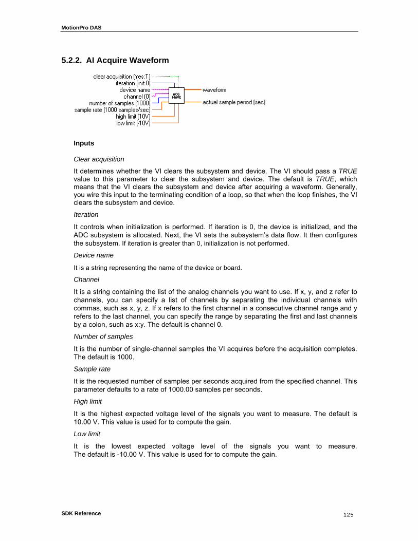
MotionPro DAS
SDK Reference 125
5.2.2. AI Acquire Waveform
Inputs
Clear acquisition
It determines whether the VI clears the subsystem and device. The VI should pass a TRUE value to this parameter to clear the subsystem and device. The default is TRUE, which means that the VI clears the subsystem and device after acquiring a waveform. Generally, you wire this input to the terminating condition of a loop, so that when the loop finishes, the VI clears the subsystem and device.
Iteration
It controls when initialization is performed. If iteration is 0, the device is initialized, and the ADC subsystem is allocated. Next, the VI sets the subsystem’s data flow. It then configures the subsystem. If iteration is greater than 0, initialization is not performed.
Device name
It is a string representing the name of the device or board.
Channel
It is a string containing the list of the analog channels you want to use. If x, y, and z refer to channels, you can specify a list of channels by separating the individual channels with commas, such as x, y, z. If x refers to the first channel in a consecutive channel range and y refers to the last channel, you can specify the range by separating the first and last channels by a colon, such as x:y. The default is channel 0.
Number of samples
It is the number of single-channel samples the VI acquires before the acquisition completes. The default is 1000.
Sample rate
It is the requested number of samples per seconds acquired from the specified channel. This parameter defaults to a rate of 1000.00 samples per seconds.
High limit
It is the highest expected voltage level of the signals you want to measure. The default is 10.00 V. This value is used for to compute the gain.
Low limit
It is the lowest expected voltage level of the signals you want to measure. The default is -10.00 V. This value is used for to compute the gain.

MotionPro DAS
SDK Reference 126
Outputs
Waveform
It is a one-dimensional array containing scaled analog input data in volts.
Actual sample period
It is the actual interval between samples, which is the inverse of the actual sample rate. The actual sample period can differ from the requested sample rate, depending on the capabilities of your hardware.
Remarks This VI acquires a waveform (multiple voltage readings at a specified sampling rate) on a single analog input channel and returns the acquired data. If an error occurs, a dialog box appears, giving you the option to stop or to continue. This VI uses only the first channel in channel. All other channels are ignored. High limit and low limit do not refer to the specific range of the ADC subsystem. Instead, these values indicate the actual voltage levels that may need to be measured. These values are then used to calculate the best gain to render the best possible resolution.
See also: “AI Acquire Waveforms”
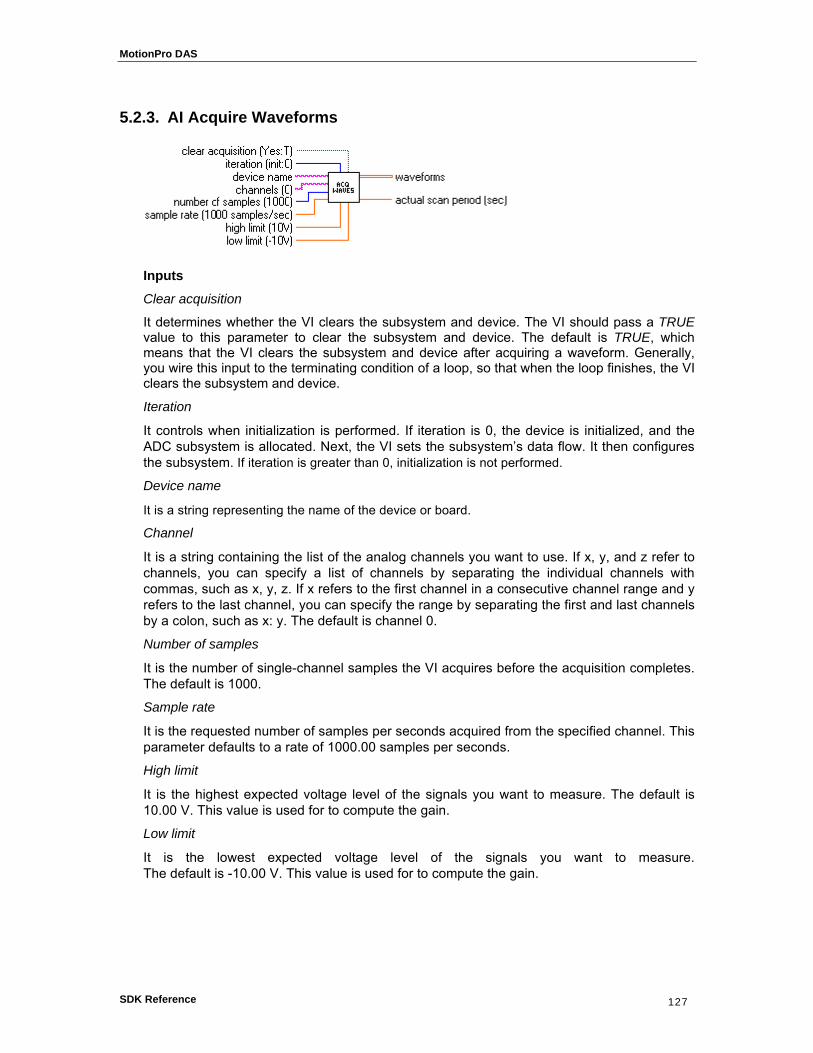
MotionPro DAS
SDK Reference 127
5.2.3. AI Acquire Waveforms
Inputs
Clear acquisition
It determines whether the VI clears the subsystem and device. The VI should pass a TRUE value to this parameter to clear the subsystem and device. The default is TRUE, which means that the VI clears the subsystem and device after acquiring a waveform. Generally, you wire this input to the terminating condition of a loop, so that when the loop finishes, the VI clears the subsystem and device.
Iteration
It controls when initialization is performed. If iteration is 0, the device is initialized, and the ADC subsystem is allocated. Next, the VI sets the subsystem’s data flow. It then configures the subsystem. If iteration is greater than 0, initialization is not performed.
Device name
It is a string representing the name of the device or board.
Channel
It is a string containing the list of the analog channels you want to use. If x, y, and z refer to channels, you can specify a list of channels by separating the individual channels with commas, such as x, y, z. If x refers to the first channel in a consecutive channel range and y refers to the last channel, you can specify the range by separating the first and last channels by a colon, such as x: y. The default is channel 0.
Number of samples
It is the number of single-channel samples the VI acquires before the acquisition completes. The default is 1000.
Sample rate
It is the requested number of samples per seconds acquired from the specified channel. This parameter defaults to a rate of 1000.00 samples per seconds.
High limit
It is the highest expected voltage level of the signals you want to measure. The default is 10.00 V. This value is used for to compute the gain.
Low limit
It is the lowest expected voltage level of the signals you want to measure. The default is -10.00 V. This value is used for to compute the gain.
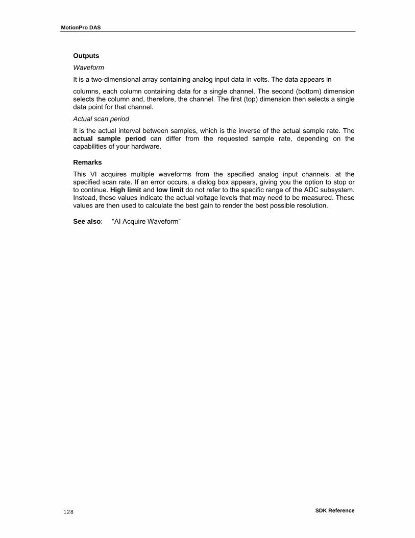
MotionPro DAS
SDK Reference 128
Outputs
Waveform
It is a two-dimensional array containing analog input data in volts. The data appears in
columns, each column containing data for a single channel. The second (bottom) dimension selects the column and, therefore, the channel. The first (top) dimension then selects a single data point for that channel.
Actual scan period
It is the actual interval between samples, which is the inverse of the actual sample rate. The actual sample period can differ from the requested sample rate, depending on the capabilities of your hardware.
Remarks This VI acquires multiple waveforms from the specified analog input channels, at the specified scan rate. If an error occurs, a dialog box appears, giving you the option to stop or to continue. High limit and low limit do not refer to the specific range of the ADC subsystem. Instead, these values indicate the actual voltage levels that may need to be measured. These values are then used to calculate the best gain to render the best possible resolution.
See also: “AI Acquire Waveform”

MotionPro DAS
SDK Reference 129
5.2.4. AI Sample Channel
Inputs
Iteration
It controls when initialization is performed. If iteration is 0, the device is initialized, and the analog-to-digital subsystem is allocated. Next, the VI sets the subsystem’s data flow. It then configures the subsystem. If iteration is greater than 0, initialization is not performed.
Device name
It is a string representing the name of the device or board.
Channel
It is a string containing the list of the analog channels you want to use. If x, y, and z refer to channels, you can specify a list of channels by separating the individual channels with commas, such as x, y, z. If x refers to the first channel in a consecutive channel range and y refers to the last channel, you can specify the range by separating the first and last channels by a colon, such as x: y. The default is channel 0.
High limit
It is the highest expected voltage level of the signals you want to measure. The default is 10.00 V. This value is used for to compute the gain.
Low limit
It is the lowest expected voltage level of the signals you want to measure. The default is -10.00 V. This value is used for to compute the gain.
Clear acquisition
It determines whether the VI clears the subsystem and device. The VI should pass a TRUE value to this parameter to clear the subsystem and device. The default is TRUE, which means that the VI clears the subsystem and device after acquiring a waveform. Generally, you wire this input to the terminating condition of a loop, so that when the loop finishes, the VI clears the subsystem and device.
Outputs
Sample
It contains the scaled analog input data for the specified channel in volts.
Remarks This VI performs a single, un-timed measurement of a channel. If an error occurs, a dialog box appears, giving you the option to stop or to continue. This VI uses only the first channel in channel. All other channels are ignored. High limit and low limit do not refer to the specific range of the ADC subsystem. Instead, these values indicate the actual voltage levels that need to be measured. These values are then used to calculate the best gain to give the best possible resolution.
See also: “AI Sample Channels”
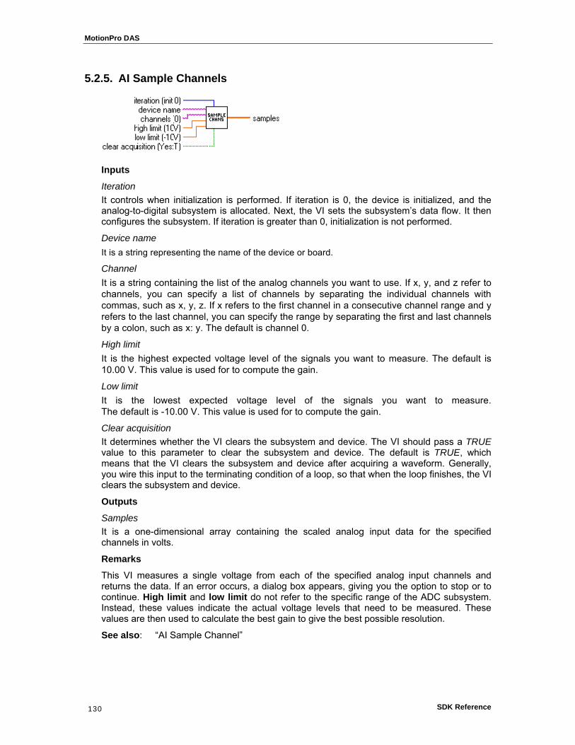
MotionPro DAS
SDK Reference 130
5.2.5. AI Sample Channels
Inputs
Iteration It controls when initialization is performed. If iteration is 0, the device is initialized, and the analog-to-digital subsystem is allocated. Next, the VI sets the subsystem’s data flow. It then configures the subsystem. If iteration is greater than 0, initialization is not performed.
Device name It is a string representing the name of the device or board.
Channel It is a string containing the list of the analog channels you want to use. If x, y, and z refer to channels, you can specify a list of channels by separating the individual channels with commas, such as x, y, z. If x refers to the first channel in a consecutive channel range and y refers to the last channel, you can specify the range by separating the first and last channels by a colon, such as x: y. The default is channel 0.
High limit It is the highest expected voltage level of the signals you want to measure. The default is 10.00 V. This value is used for to compute the gain.
Low limit It is the lowest expected voltage level of the signals you want to measure. The default is -10.00 V. This value is used for to compute the gain.
Clear acquisition It determines whether the VI clears the subsystem and device. The VI should pass a TRUE value to this parameter to clear the subsystem and device. The default is TRUE, which means that the VI clears the subsystem and device after acquiring a waveform. Generally, you wire this input to the terminating condition of a loop, so that when the loop finishes, the VI clears the subsystem and device.
Outputs
Samples It is a one-dimensional array containing the scaled analog input data for the specified channels in volts.
Remarks This VI measures a single voltage from each of the specified analog input channels and returns the data. If an error occurs, a dialog box appears, giving you the option to stop or to continue. High limit and low limit do not refer to the specific range of the ADC subsystem. Instead, these values indicate the actual voltage levels that need to be measured. These values are then used to calculate the best gain to give the best possible resolution.
See also: “AI Sample Channel”

MotionPro DAS
SDK Reference 131
55..33.. AAnnaalloogg IInnppuutt IInntteerrmmeeddiiaattee VVIIss
5.3.1. Overview:
The Analog Input Intermediate VIs which performs basic input operations are the following:
AI Config configures the ADC subsystem for use on a specific set of channels.
AI Start starts an analog input operation. It sets the subsystem’s clock and trigger conditions, allocates buffers, and starts an operation.
AI Read reads data from a buffered acquisition and converts the data, on request, into voltages.
AI Clear clears the ADC subsystem and board associates with the subsystem ID and device ID.
MotionPro DAS
SDK Reference 132
5.3.2. AI Config
Inputs
Device name
It is a string representing the name of the device or board.
Channels
It is a one-dimensional array of the analog channels you want to use. If x, y, and z refer to channels, you can specify a list of channels by separating the individual channels with commas, such as x, y, z. If x refers to the first channel in a consecutive channel range and y refers to the last channel, you can specify the range by separating the first and last channels by a colon, such as x: y. The default is channel 0.
Limits
It is an array of clusters. Each array element assigns the limits for the channel specified by the corresponding element of channels. If fewer elements in this array exist than channels, the VI uses the last element of input limits for the remaining channels. The default for input limits is a single element array, with 10.00 V as the high limit and −10.00 V as the low limit.
• High limit is the highest expected voltage level of the signals you want to measure. The default is 10.00 V. This value is used to compute the gain.
• Low limit is the lowest expected voltage level of the signals you want to measure. The default is −10.00 V. This value is used to compute the gain.
Error In
It is the error status from a previous VI. If error in contains an error, this VI simply returns the error in value in error out. The default is no error.
Subsystem info
It contains information required to configure the subsystem. Data flow contains the subsystem’s new data flow mode. The default value is continuous. Valid values are 0 (continuous), 1 (single value), 2 (continuous pre-trigger). Wrap contains the subsystem’s wrap mode. The default value is none. Valid values are 0 (none), 1 (multiple), 2 (single).
Outputs
Device handle out
It is the numeric value used to represent the board.
Subsystem handle out
It is the numeric value used to represent the subsystem.

MotionPro DAS
SDK Reference 133
Number of channels
It is the number of channels parsed from the channel parameter.
Error out
It contains error in if error in contains an error; otherwise, error out contains the error status of the VI.
Remarks This VI configures the analog-to-digital subsystem for use on a specified set of channels. It performs this function in the following manner:
1. Before performing any configuration, AI Config checks to see if the error in cluster indicates whenever an error has already occurred. If so, then this VI does nothing and returns the error in cluster unmodified in error out. In this case, device handle out, subsystem handle out, and number of channels are all 0. If the error in cluster is clear, this VI configures the subsystem for analog input acquisition.
2. The VI creates a device handle from the specified device name.
3. The VI allocates the analog-to-digital subsystem of the device and creates a subsystem handle.
4. The VI calls sets the Data Flow and Wrap Mode, using the values in the subsystem info cluster as parameters.
5. The VI determines the channels to configure with Parse Channels.
6. Sets the size of the subsystems channel list to the number of channels being configured.
7. For each channel being configured, AI Config places an entry in the channel list.
8. AI Config then computes the gain based on the input limits. It then sets the gain.
See also: “AI Clear”, “AI Stop”
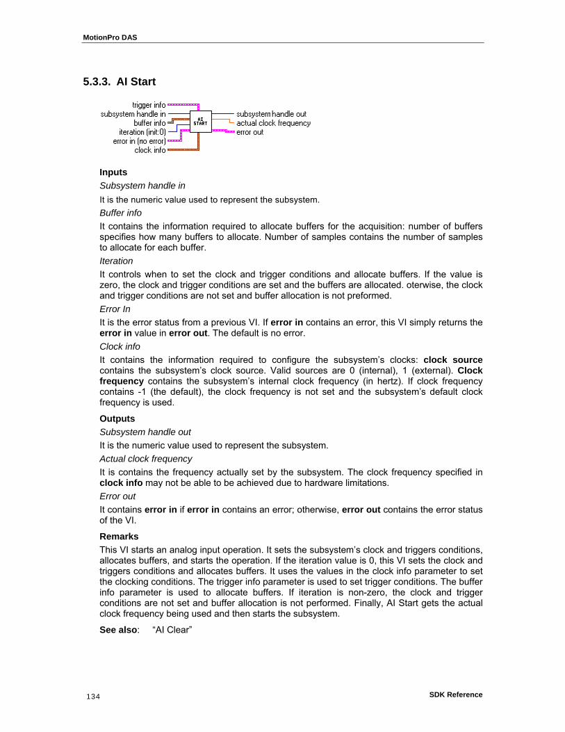
MotionPro DAS
SDK Reference 134
5.3.3. AI Start
Inputs Subsystem handle in It is the numeric value used to represent the subsystem. Buffer info It contains the information required to allocate buffers for the acquisition: number of buffers specifies how many buffers to allocate. Number of samples contains the number of samples to allocate for each buffer. Iteration It controls when to set the clock and trigger conditions and allocate buffers. If the value is zero, the clock and trigger conditions are set and the buffers are allocated. oterwise, the clock and trigger conditions are not set and buffer allocation is not preformed. Error In It is the error status from a previous VI. If error in contains an error, this VI simply returns the error in value in error out. The default is no error. Clock info It contains the information required to configure the subsystem’s clocks: clock source contains the subsystem’s clock source. Valid sources are 0 (internal), 1 (external). Clock frequency contains the subsystem’s internal clock frequency (in hertz). If clock frequency contains -1 (the default), the clock frequency is not set and the subsystem’s default clock frequency is used.
Outputs Subsystem handle out It is the numeric value used to represent the subsystem. Actual clock frequency It is contains the frequency actually set by the subsystem. The clock frequency specified in clock info may not be able to be achieved due to hardware limitations. Error out It contains error in if error in contains an error; otherwise, error out contains the error status of the VI.
Remarks This VI starts an analog input operation. It sets the subsystem’s clock and triggers conditions, allocates buffers, and starts the operation. If the iteration value is 0, this VI sets the clock and triggers conditions and allocates buffers. It uses the values in the clock info parameter to set the clocking conditions. The trigger info parameter is used to set trigger conditions. The buffer info parameter is used to allocate buffers. If iteration is non-zero, the clock and trigger conditions are not set and buffer allocation is not performed. Finally, AI Start gets the actual clock frequency being used and then starts the subsystem.
See also: “AI Clear”
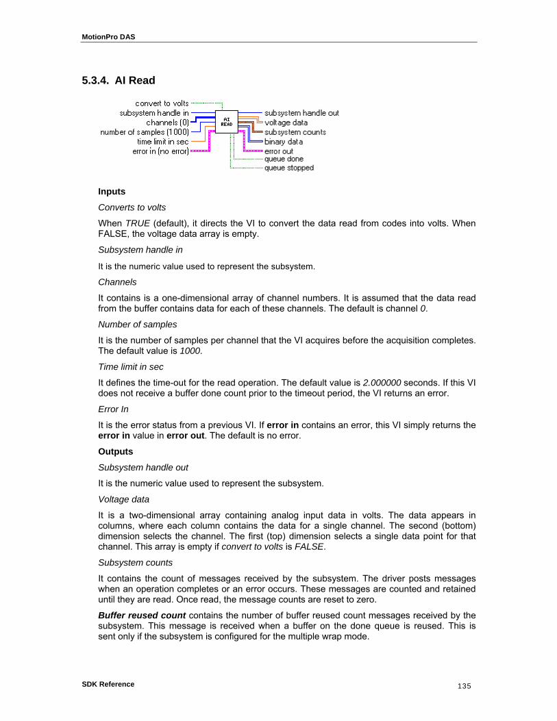
MotionPro DAS
SDK Reference 135
5.3.4. AI Read
Inputs
Converts to volts
When TRUE (default), it directs the VI to convert the data read from codes into volts. When FALSE, the voltage data array is empty.
Subsystem handle in
It is the numeric value used to represent the subsystem.
Channels
It contains is a one-dimensional array of channel numbers. It is assumed that the data read from the buffer contains data for each of these channels. The default is channel 0.
Number of samples
It is the number of samples per channel that the VI acquires before the acquisition completes. The default value is 1000.
Time limit in sec
It defines the time-out for the read operation. The default value is 2.000000 seconds. If this VI does not receive a buffer done count prior to the timeout period, the VI returns an error.
Error In
It is the error status from a previous VI. If error in contains an error, this VI simply returns the error in value in error out. The default is no error.
Outputs
Subsystem handle out
It is the numeric value used to represent the subsystem.
Voltage data
It is a two-dimensional array containing analog input data in volts. The data appears in columns, where each column contains the data for a single channel. The second (bottom) dimension selects the channel. The first (top) dimension selects a single data point for that channel. This array is empty if convert to volts is FALSE.
Subsystem counts
It contains the count of messages received by the subsystem. The driver posts messages when an operation completes or an error occurs. These messages are counted and retained until they are read. Once read, the message counts are reset to zero.
Buffer reused count contains the number of buffer reused count messages received by the subsystem. This message is received when a buffer on the done queue is reused. This is sent only if the subsystem is configured for the multiple wrap mode.

MotionPro DAS
SDK Reference 136
Buffer done count contains the number of buffer done count messages received by the subsystem. This message is received whenever a buffer transfer operation completes. An input subsystem generates this message when a buffer is filled with post-trigger data.
Pre-trigger done count contains the number of pre-trigger buffer done messages received by the system. This message is sent whenever a buffer transfer operation completes. An input subsystem generates this message when a buffer is filled. An output subsystem generates this message when a buffer is emptied.
Queue done count contains the number of queue done messages received by the subsystem. This message is generated when the subsystem stops as a result of an exhausted ready queue. Note that this condition usually occurs only when the subsystem is configured for no buffer wrap mode.
Queue stopped count contains the number of queue stopped messages received by the subsystem. This message is sent when the operation is stopped.
Trigger error count contains the number of trigger error messages received by the subsystem. This message is sent when a trigger error occurs. A trigger error occurs when unexpected software or external triggers are received during data transfer. If this error message occurs, continuous operation is halted. For input subsystems, the error usually causes a partially-filled buffer to be placed on the done queue.
Overrun error count contains the number of overrun error messages received by the subsystem. This message is sent when the hardware of an input subsystem runs out of buffer space. An overrun error indicates that the input data was not transferred before the next sample was received. This error occurs when data transfer from the hardware to the driver cannot keep up with the input clock rate. To avoid this error, reduce the sampling rate or increase the size of the buffers. Note: If this error message occurs, continuous operation is halted. For input subsystems, the error usually causes a partially-filled buffer to be placed on the done queue.
Underrun error count contains the number of underrun error messages received by the subsystem. This message is sent when the hardware of an output subsystem runs out of data. This error occurs when data transfer from the driver to the hardware cannot keep up with the output clock rate. To avoid this error, slow down the clock rate or increase the size of the buffers. Note: If this error message occurs, continuous operation is halted. For input subsystems, the error usually causes a partially-filled buffer to be placed on the done queue.
Binary data
It is a two-dimensional array containing non scaled analog input data. The data appears in columns, where each column contains the data for a single channel. The second (or bottom) dimension selects the channel. The first (or top) dimension selects a single data point for that channel.
Error out
It contains error in if error in contains an error; otherwise, it contains the VI error status.
Queue done
It is TRUE if a queue done message was received.
Queue stopped
It is TRUE if a queue stopped message was received.
Remarks This VI reads data from a buffered acquisition and converts the data, on request, into voltages. This VI acquires the number and type of messages received by the subsystem. If a

MotionPro DAS
SDK Reference 137
trigger error, overrun error, or underrun error is received, the VI terminates and returns the appropriate error code. If the time limit is exceeded prior to receipt of a buffer done message, the VI terminates and reports a time out error. Upon receiving a buffer done message, the VI gets the data buffer from the done queue, then copy the data from the buffer into the binary data array. After that, it puts the buffer back on the ready queue so it can be reused at a later time. If convert to volts is TRUE (the default), the binary data is converted into voltages based on the gain being used by the channel and is returned in the voltage data array.
See also: “AI Start”, “AI Clear”

MotionPro DAS
SDK Reference 138
5.3.5. AI Clear
Inputs
Device handle
It is the numeric value used to represent the board.
Subsystem handle
It is the numeric value used to represent the subsystem.
Error In
It is the error status from a previous VI. If error in contains an error, this VI simply returns the error in value in error out. The default is no error.
Outputs Error out
It contains error in if error in contains an error; otherwise, it contains the VI error status.
Remarks This VI clears the ADC subsystem and board associated with the subsystem handle and device handle. AI Clear halts the acquisition associated with the subsystem handle. If the subsystem was running in continuous mode, it releases each buffer used by the subsystem. The VI releases all the resources associated with the subsystem and board. Before beginning a new acquisition, you must call the AI Config VI.
See also: “AI Start”

MotionPro DAS
SDK Reference 139
55..44.. AAnnaalloogg IInnppuutt UUttiilliittyy VVIIss
5.4.1. Overview
The Analog Input Utility VIs provide support for the Easy and Intermediate VIs and are the following:
AI Waveform Scan acquires the specified number of samples at the specified sample rate and returns all the data acquired.
AI Read One Scan performs an immediate, non timed measurement of a group of one or more channels. The measurements are returned in an array of voltages.
AI Continuous Scan performs continuous, time-sampled measurements of a group of one or more channels. Use this VI to scan a group of channels indefinitely, such as in data-logging applications.

MotionPro DAS
SDK Reference 140
5.4.2. AI Waveform Scan
Inputs
Clock info
It contains the information required to configure the subsystem’s clocks.
Clock source contains the subsystem’s clock source. Valid sources are 0 (internal), 1 (external).
Subsystem info
It contains information required to configure the subsystem. Data flow contains the subsystem’s new data flow mode. The default value is continuous. Valid values are 0 (continuous), 1 (single value), 2 (continuous pre-trigger). Wrap contains the subsystem’s wrap mode. The default value is none. Valid values are 0 (none), 2 (multiple), 3 (single).
Input Limits
It is an array of clusters. Each array element assigns the limits for the channel specified by the corresponding element of channels. If fewer elements in this array exist than channels, the VI uses the last element of input limits for the remaining channels. The default for input limits is a single element array, with 10.00 V as the high limit and −10.00 V as the low limit.
Device name
It is a string representing the name of the device or board.
Channels
It is a one-dimensional array of the analog channels you want to use. If x, y, and z refer to channels, you can specify a list of channels by separating the individual channels with commas, such as x, y, z. If x refers to the first channel in a consecutive channel range and y refers to the last channel, you can specify the range by separating the first and last channels by a colon, such as x: y. The default is channel 0.
Time limit in sec
It defines the timeout limit. If the VI does not receive a buffer of data prior to the timeout period, it returns an error. The default value is 10.000000 seconds. If the clock source is internal and the trigger is software, the VI will not use the timeout limit in sec. Instead, it calculates the timeout period based on the sample rate and number of samples.
Number of samples
It is the number of single-channel samples the VI acquires before the acquisition completes. This parameter defaults to 1000.

MotionPro DAS
SDK Reference 141
Sample rate
It is the requested number of samples per second that the VI acquires from the channel list. For example, if you define two channels, the sample rate per channel is half of the defined sample rate. This parameter defaults to a rate of 1000.00 samples per second.
Error In
It is the error status from a previous VI. If error in contains an error, this VI simply returns the error in value in error out. The default is no error.
Iteration
It controls when initialization is performed. If iteration is 0, the device is initialized, and the ADC subsystem is allocated. Next, the VI sets the subsystem’s data flow. It then configures the subsystem. If iteration is greater than 0, initialization is not performed.
Number of buffers
It contains the number of buffers to allocate.
Trigger info
It contains the information required to configure the subsystem’s trigger information. Trigger contains the subsystem’s trigger source. Valid trigger sources are 0 (software), 1 (external), 2 (positive threshold), 3 (extra). Retrigger mode contains the subsystem’s retrigger mode. Valid retrigger modes are 0 (internal), 1 (scan per trigger), 2 (extra). Enable triggered scan enables (TRUE) or disables (FALSE), the subsystem’s triggered scan mode. Retrigger frequency sets the subsystem’s retrigger frequency. The default retrigger frequency is -1.00. This value keeps the retrigger frequency the same as the subsystem’s current value. Pre-trigger contains the subsystem’s pre-trigger source. Valid pre-trigger sources are 0 (software), 1 (external), 2 (positive threshold), 3 (extra). Retrigger contains the subsystem’s retrigger source. Valid retrigger sources are 0 (software), 1 (external), 2 (positive threshold), 3 (extra).
Clear acquisition
It determines whether the VI clears the subsystem and device. The VI should pass a TRUE value to this parameter to clear the subsystem and device. The default is TRUE, which means that the VI clears the subsystem and device after acquiring a set of samples. Generally you wire this input to the terminating condition of a loop, so that when the loop finishes, the VI clears the subsystem and device.
Outputs
Waveform data
It is a two-dimensional array containing analog input data in volts. The data appears in columns, each column containing data for a single channel. The second (bottom) dimension selects the column and, therefore, the channel. The first (top) dimension then selects a single data point for that channel.
Actual sample period
It is the time between samples, which is the inverse of the sample rate the VI used to acquire the data. The actual sample period may differ slightly from the requested sample rate, depending on the capabilities of your hardware.
Number of channels
It contains the number of channels parsed from the channels parameter.

MotionPro DAS
SDK Reference 142
Error out
It contains error in if error in contains an error; otherwise, it contains the VI error status.
Remarks This VI acquires the specified number of samples at the specified sample rate and returns all the data acquired. If you execute this VI in a loop you can continuously acquire samples. Set iteration to 0 on the first call to invoke AI Configure to configure the device and subsystem, and set clear acquisition to TRUE on the last call to call AI Clear to clear the subsystem and device. Each call to AI Waveform Scan invokes AI Start and AI Read to acquire the required samples. If you need to make multiple calls to this VI to read channels on multiple devices, make a copy of the VI, and give it a new name. Then call the copy. You can create and call as many copies as you need.

MotionPro DAS
SDK Reference 143
5.4.3. AI Continuous Scan
Inputs
Convert to volts
It when TRUE, the default, causes the binary data to be converted into voltages.
Clock info
It contains the information required to configure the subsystem’s clocks: Clock source contains the subsystem’s clock source. Valid sources are 0 (internal) and 1 (external).
Subsystem info
It contains information required to configure the subsystem.
Data flow contains the subsystem’s new data flow mode. The default value is continuous. Valid values are 0 (continuous), 1 (single value), 2 (continuous pretrigger). Note that for purposes of this VI, the default value (0) is the only valid value.
Wrap contains the subsystem’s wrap mode. The default value is none. Valid values are 0 (none), 1 (multiple), 2 (single).
Input Limits
It is an array of clusters. Each array element assigns the limits for the channel specified by the corresponding element of channels. If fewer elements in this array exist than channels, the VI uses the last element of input limits for the remaining channels. The default for input limits is a single element array, with 10.00 V as the high limit and −10.00 V as the low limit.
Device name
It is a string representing the name of the device or board.
Channels
It is a one-dimensional array of the analog channels you want to use. If x, y, and z refer to
channels, you can specify a list of channels by separating the individual channels with commas, such as x, y, z. If x refers to the first channel in a consecutive channel range and y refers to the last channel, you can specify the range by separating the first and last channels by a colon, such as x: y. The default is channel 0.
Timeout limit in sec
It defines the timeout limit. If the VI does not receive a buffer of data prior to the timeout period, it returns an error. The default value is 10.000000 seconds.

MotionPro DAS
SDK Reference 144
If the clock source is internal and the trigger is software, the VI will not use the timeout limit in sec. Instead, it calculates the timeout period based on the sample rate and number of samples.
Number of samples
It is the number of single-channel samples the VI acquires before the acquisition completes. This parameter defaults to 1000.
Sample rate
It is the requested number of samples per second that the VI acquires from the channel list. For example, if you define two channels, the sample rate per channel is half of the defined sample rate. This parameter defaults to a rate of 1000.00 samples per second.
Error In
It is the error status from a previous VI. If error in contains an error, this VI simply returns the error in value in error out. The default is no error.
Iteration
It controls when initialization is performed. If iteration is 0, the device is initialized, and the ADC subsystem is allocated. Next, the VI sets the subsystem’s data flow. It then configures the subsystem. If iteration is greater than 0, initialization is not performed.
Number of buffers
It contains the number of buffers to allocate.
Trigger info
It contains the information required to configure the subsystem’s trigger information.
Trigger contains the subsystem’s trigger source. Valid trigger sources are 0 (software), 1 (external), 2 (positive threshold), 3 (extra).
Retrigger mode contains the subsystem’s retrigger mode. Valid retrigger modes are 0 (internal), 1 (scan per trigger), 2 (extra).
Enable triggered scan enables (TRUE) or disables (FALSE), the subsystem’s triggered scan mode.
Retrigger frequency sets the subsystem’s retrigger frequency. The default retrigger frequency is -1.00. This value keeps the retrigger frequency the same as the subsystem’s current value.
Pre-trigger contains the subsystem’s pre-trigger source. Valid pre-trigger sources are 0 (software), 1 (external), 2 (positive threshold), 3 (extra).
Retrigger contains the subsystem’s retrigger source. Valid retrigger sources are 0 (software), 1 (external), 2 (positive threshold), 3 (extra).
Clear acquisition
It determines whether the VI clears the subsystem and device. The VI should pass a TRUE value to this parameter to clear the subsystem and device. The default is TRUE, which means that the VI clears the subsystem and device after acquiring a set of samples. Generally you wire this input to the terminating condition of a loop, so that when the loop finishes, the VI clears the subsystem and device.
Outputs
Waveform data
It is a two-dimensional array containing analog input data in volts. The data appears in columns, each column containing data for a single channel. The second (bottom) dimension

MotionPro DAS
SDK Reference 145
selects the column and, therefore, the channel. The first (top) dimension then selects a single data point for that channel.
Binary data
It is a two-dimensional array containing un-scaled analog input data. The data appears in columns where each column contains the data for a single channel. The second (or bottom) dimension selects the channel column. The first (or top) dimension selects a single data point for that channel.
Actual sample period
It is the time between samples, which is the inverse of the sample rate the VI used to acquire the data. The actual sample period may differ slightly from the requested sample rate, depending on the capabilities of your hardware.
Number of channels
It contains the number of channels parsed from the channels parameter.
Error out
It contains error in if error in contains an error; otherwise, it contains the VI error status.
Remarks This VI makes continuous, time-sampled measurements of a group of channels. Use AI Continuous Scan to scan a group of channels indefinitely, such as in data-logging applications. If you execute this VI in a loop, you can continuously acquire samples. Set iteration to 0 on the first call to invoke AI Configure and call AI Start to configure the device and subsystem and start acquisition. Set clear acquisition to TRUE on the last call to call AI Clear to clear the subsystem and device. If the buffer size and number of buffers allocated are adequate to support the speed of the board, the acquisition will be gap-free. Each call to AI Waveform Scan invokes AI Read to acquire the required samples. If you need to make multiple calls to this VI to read channels on multiple devices, make a copy of the VI, and give it a new name. Then call the copy. You can create and call as many copies as you need.

MotionPro DAS
SDK Reference 146
5.4.4. AI Read One Scan
Inputs
Device name
It is a string representing the name of the device or board.
Channels
It is a one-dimensional array of strings each containing a list of the analog channels you want to use. If x, y, and z refer to channels, you can specify a list of channels by separating the individual channels with commas, such as x,y,z. If x refers to the first channel in a consecutive channel range and y refers to the last channel, you can specify the range by separating the first and last channels by a colon, such as x:y. The default is channel 0.
High limit
It is the highest expected voltage level of the signals you want to measure. The default is 10.00 V. This value is used for to compute the gain.
Low limit
It is the lowest expected voltage level of the signals you want to measure. The default is -10.00 V. This value is used for to compute the gain.
Error In
It is the error status from a previous VI. If error in contains an error, this VI simply returns the error in value in error out. The default is no error.
Iteration
It controls when initialization is performed. If iteration is 0, the device is initialized, and the ADC subsystem is allocated. Next, the VI sets the subsystem’s data flow. It then configures the subsystem. If iteration is greater than 0, initialization is not performed.
Clear acquisition
It determines whether the VI clears the subsystem and device. The VI should pass a TRUE value to this parameter to clear the subsystem and device. The default is TRUE, which means that the VI clears the subsystem and device after acquiring a waveform. Generally, you wire this input to the terminating condition of a loop, so that when the loop finishes, the VI clears the subsystem and device.
Outputs
Samples
It is a one-dimensional array containing analog input data in volts. The data appears in columns, each column containing data for a single channel.
Error out
It contains error in if error in contains an error; otherwise, it contains the VI error status.
MotionPro DAS
SDK Reference 147
Remarks This VI performs an immediate, non timed measurement of a group of one or more channels. The measurements are returned in an array of voltages. If you execute this VI in a loop, you can continuously read from channel. Set iteration to 0 on the first call to configure the channel, and set clear port to TRUE on the last call to clear the subsystem and device. If you need to make multiple calls to this VI to read channels on multiple devices, make a copy of the VI, and give it a new name. Then call the copy. You can create and call as many copies as you need.

MotionPro DAS
SDK Reference 148
55..55.. AAnnaalloogg OOuuttppuutt EEaassyy VVIIss
5.5.1. Overview
Analog Output Easy Virtual Instruments perform simple analog output operations.
AO Generate Waveform outputs a specified number of samples at a specified update rate to a single output channel.
AO Generate Waveforms outputs a specified number of samples at the specified update rate to a list of output channels.
AO Update Channel writes a single voltage value to an analog output channel.
AO Update Channels write single voltage values to a list of analog output channels.

MotionPro DAS
SDK Reference 149
5.5.2. AO Generate Waveform
Inputs
Iteration
It controls when initialization is performed. If iteration is 0, the device is initialized, and the DAC subsystem is allocated. Next, the VI sets the subsystem’s data flow. It then configures the subsystem. If iteration is greater than 0, initialization is not performed.
Device name
It is a string representing the name of the device or board.
Channel
It is a string containing the list of the analog channels you want to use. If x, y, and z refer to channels, you can specify a list of channels by separating the individual channels with commas, such as x, y, z. If x refers to the first channel in a consecutive channel range and y refers to the last channel, you can specify the range by separating the first and last channels by a colon, such as x: y. The default is channel 0.
Update Rate
It is the requested number of samples per second the VI outputs to the specified channel.
This parameter defaults to a rate of 1000.00 samples per second.
Waveform
It is a one-dimensional array containing scaled analog output data in volts.
Clear acquisition
It determines whether the VI clears the subsystem and device. The VI should pass a TRUE value to this parameter to clear the subsystem and device. The default is TRUE, which means that the VI clears the subsystem and device after acquiring a waveform. Generally, you wire this input to the terminating condition of a loop, so that when the loop finishes, the VI clears the subsystem and device.
Remarks This VI outputs a specified number of samples at the specified update rate to a single output channel. If an error occurs, a dialog box appears, giving you the option to stop or to continue. This VI only uses the first channel in channel. All other channels are ignored.

MotionPro DAS
SDK Reference 150
5.5.3. AO Generate Waveforms
Inputs
Iteration
It controls when initialization is performed. If iteration is 0, the device is initialized, and the DAC subsystem is allocated. Next, the VI sets the subsystem’s data flow. It then configures the subsystem. If iteration is greater than 0, initialization is not performed.
Device name
It is a string representing the name of the device or board.
Channel
It is a string containing the list of the analog channels you want to use. If x, y, and z refer to channels, you can specify a list of channels by separating the individual channels with commas, such as x, y, z. If x refers to the first channel in a consecutive channel range and y refers to the last channel, you can specify the range by separating the first and last channels by a colon, such as x: y. The default is channel 0.
Update Rate
It is the requested number of samples per second the VI outputs to the specified channel.
This parameter defaults to a rate of 1000.00 samples per second.
Waveforms
It is a two-dimensional array containing scaled analog output data in volts.
Clear acquisition
It determines whether the VI clears the subsystem and device. The VI should pass a TRUE value to this parameter to clear the subsystem and device. The default is TRUE, which means that the VI clears the subsystem and device after acquiring a waveform. Generally, you wire this input to the terminating condition of a loop, so that when the loop finishes, the VI clears the subsystem and device.
Remarks This VI outputs a specified number of samples at the specified update rate to a list of output channels. If an error occurs, a dialog box appears, giving you the option to stop or to continue.
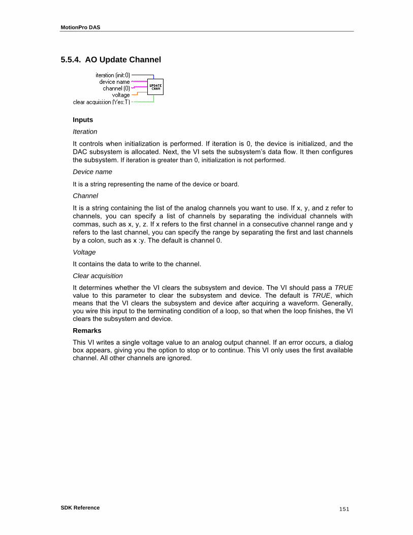
MotionPro DAS
SDK Reference 151
5.5.4. AO Update Channel
Inputs
Iteration
It controls when initialization is performed. If iteration is 0, the device is initialized, and the DAC subsystem is allocated. Next, the VI sets the subsystem’s data flow. It then configures the subsystem. If iteration is greater than 0, initialization is not performed.
Device name
It is a string representing the name of the device or board.
Channel
It is a string containing the list of the analog channels you want to use. If x, y, and z refer to channels, you can specify a list of channels by separating the individual channels with commas, such as x, y, z. If x refers to the first channel in a consecutive channel range and y refers to the last channel, you can specify the range by separating the first and last channels by a colon, such as x :y. The default is channel 0.
Voltage
It contains the data to write to the channel.
Clear acquisition
It determines whether the VI clears the subsystem and device. The VI should pass a TRUE value to this parameter to clear the subsystem and device. The default is TRUE, which means that the VI clears the subsystem and device after acquiring a waveform. Generally, you wire this input to the terminating condition of a loop, so that when the loop finishes, the VI clears the subsystem and device.
Remarks This VI writes a single voltage value to an analog output channel. If an error occurs, a dialog box appears, giving you the option to stop or to continue. This VI only uses the first available channel. All other channels are ignored.

MotionPro DAS
SDK Reference 152
5.5.5. AO Update Channels
Inputs
Iteration
It controls when initialization is performed. If iteration is 0, the device is initialized, and the DAC subsystem is allocated. Next, the VI sets the subsystem’s data flow. It then configures the subsystem. If iteration is greater than 0, initialization is not performed.
Device name
It is a string representing the name of the device or board.
Channel
It is a string containing the list of the analog channels you want to use. If x, y, and z refer to channels, you can specify a list of channels by separating the individual channels with commas, such as x, y, z. If x refers to the first channel in a consecutive channel range and y refers to the last channel, you can specify the range by separating the first and last channels by a colon, such as x: y. The default is channel 0.
Voltages
It is a one-dimensional array containing data to be written to the channels, one value for each channel given in the channel parameter.
Clear acquisition
It determines whether the VI clears the subsystem and device. The VI should pass a TRUE value to this parameter to clear the subsystem and device. The default is TRUE, which means that the VI clears the subsystem and device after acquiring a waveform. Generally, you wire this input to the terminating condition of a loop, so that when the loop finishes, the VI clears the subsystem and device.
Remarks This VI writes single voltage values to a list of analog output channels. If an error occurs, a dialog box appears, giving you the option to stop or to continue.

MotionPro DAS
SDK Reference 153
55..66.. AAnnaalloogg OOuuttppuutt IInntteerrmmeeddiiaattee VVIIss
5.6.1. Overview
Analog Output Intermediate Virtual Instruments perform basic analog operations.
AO Config configures the DAC subsystem for use on a specific set of channels.
AO Start starts an analog output operation. It sets the subsystem’s clock conditions and starts the operation.
AO Write writes data to analog output channels. The data is converted from volts to code prior to being output.
AO Wait waits for an analog output operation to complete.
AO Clear clears the DAC subsystem and board associates with the subsystem ID and device ID.

MotionPro DAS
SDK Reference 154
5.6.2. AO Config
Inputs
Device name
It is a string representing the name of the device or board.
Channels
It is a one-dimensional array of the analog channels you want to use. If x, y, and z refer to channels, you can specify a list of channels by separating the individual channels with commas, such as x,y,z. If x refers to the first channel in a consecutive channel range and y refers to the last channel, you can specify the range by separatine the first and last channels by a colon, such as x:y. The default is channel 0.
Limits
It is an array of clusters. Each array element assigns the output voltage limits for the channel specified by the corresponding element of channels. If fewer elements in this array exist than channels, the VI uses the last element of input limits for the remaining channels. The default for input limits is a single element array, with 10.00 V as the high limit and −10.00 V as the low limit.
High limit is the highest expected voltage level of the signals you want to output. The default is 10.00 V. This value is used to compute the gain.
Low limit is the lowest expected voltage level of the signals you want to output. The default is −10.00 V. This value is used to compute the gain.
Error In
It is the error status from a previous VI. If error in contains an error, this VI simply returns the error in value in error out. The default is no error.
Subsystem info
It contains information required to configure the subsystem.
Data flow contains the subsystem’s new data flow mode. The default value is continuous. Valid values are 0 (continuous) and 1 (single value).
Wrap contains the subsystem’s wrap mode. The default value is none. Valid values are 0 (none), 1 (multiple), 2 (single)
Outputs Numeric channels
It contains all of the channels parsed from the channel string array in the order in which they are operated on.
Device handle out
It is the numeric value used to represent the board.

MotionPro DAS
SDK Reference 155
Subsystem handle out
It is the numeric value used to represent the subsystem.
Number of channels
It is the number of channels parsed from the channel parameter.
Error out
It contains error in if error in contains an error; otherwise, error out contains the error status of the VI.
Remarks
This VI configures the digital-to-analog subsystem for use on a specified set of channels. It performs this function in the following manner:
1. Before performing any configuration, AO Config checks to see if the error in cluster indicates an error has already occurred. If so, this VI does nothing and returns the error in cluster unmodified in error out. In this case device handle out, subsystem handle out, and number of channels are all 0. If the error cluster is clear, this VI configures the subsystem for analog output.
2. The VI creates a device handle from the specified device name.
3. The VI allocates the digital-to-analog subsystem of the device and creates a subsystem handle.
4. The VI sets Data Flow and Wrap Mode, using the values in the subsystem info cluster as parameters.
5. The VI determines which channels are being configured with Parse Channels.
6. The VI sets the size of the subsystem’s channel list to the number of channels being configured.
7. For each channel being configured AO Config places an entry in the channel list.
8. AO Config then computes the gain based on the specified output voltage limits.

MotionPro DAS
SDK Reference 156
5.6.3. AO Start
Inputs
Iteration
It controls when to set the clock conditions. If the value is zero, the clock conditions are set. If iteration is non-zero, the clock conditions are not set.
Subsystem handle in
It is the numeric value used to represent the subsystem.
Error In
It is the error status from a previous VI. If error in contains an error, this VI simply returns the error in value in error out. The default is no error.
Buffer info
It contains the information required to allocate buffers for the acquisition: Number of buffers specifies how many buffers to allocate. Number of samples contains the number of samples to allocate for each buffer.
Clock info
It contains the information required to configure the subsystem’s clocks. Clock source contains the subsystem’s clock source. Valid sources are 0 (internal), 1 (external). Clock frequency contains the subsystem’s internal clock frequency (in hertz). If clock frequency contains -1.00 (the default), the clock frequency is not set and the subsystem’s default clock frequency is used.
Outputs
Subsystem handle out
It is the numeric value used to represent the subsystem.
Actual clock frequency
It is contains the frequency actually set by the subsystem. The clock frequency
specified in clock info may not be able to be achieved due to hardware limitations.
Error out
It contains error in if error in contains an error; otherwise, error out contains the error status of the VI.
Remarks This VI starts an analog output operation. It sets the subsystem’s clock conditions and starts the operation. If the iteration value is 0, this VI sets the clock conditions. AO Start sets Clock Source and Clock Frequency using the values in the clock info parameter to set the clocking conditions. Once these values are set, this VI configures the subsystem. If iteration is non-zero, the clock conditions are not set. Finally, AO Start gets the actual clock frequency used and starts the subsystem.

MotionPro DAS
SDK Reference 157
5.6.4. AO Write
Inputs
Subsystem handle in
It is the numeric value used to represent the subsystem.
Channels
It contains is a one-dimensional array of channel numbers. It is assumed that the data read from the buffer contains data for each of these channels. The default is channel 0.
Waveform data
It is a two-dimensional array containing data to be written to the analog output channels. The data is converted to codes prior to being output. The data appears in columns, where each column contains the data for a single channel. The second (or bottom) dimension selects the channel. The first (or top) dimension selects a single data point for that channel.
Error In
It is the error status from a previous VI. If error in contains an error, this VI simply returns the error in value in error out. The default is no error.
Outputs
Subsystem handle out
It is the numeric value used to represent the subsystem.
Number of samples
It contains the total number of samples output. This value is calculated by multiplying the total number of samples per channel by the number of channels.
Error out
It contains error in if error in contains an error; otherwise, error out contains the error status of the VI.
Remarks This VI writes data to analog output channels. The data is converted from volts to codes prior to being output. After it is converted into codes, the waveform data is deposited into a buffer. The buffer is placed on the ready queue.
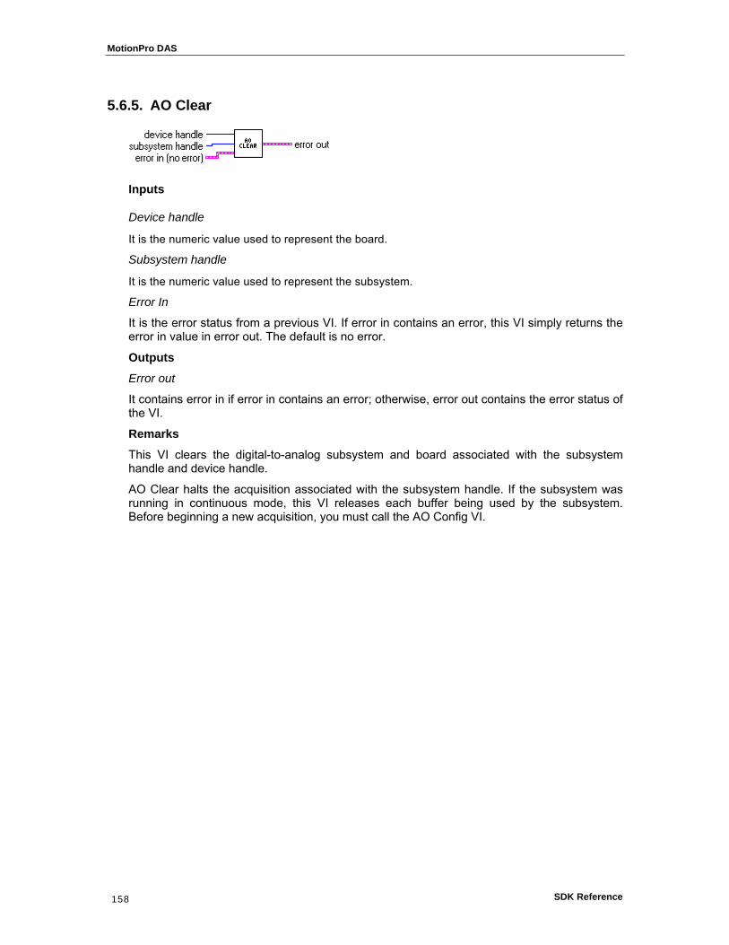
MotionPro DAS
SDK Reference 158
5.6.5. AO Clear
Inputs
Device handle
It is the numeric value used to represent the board.
Subsystem handle
It is the numeric value used to represent the subsystem.
Error In
It is the error status from a previous VI. If error in contains an error, this VI simply returns the error in value in error out. The default is no error.
Outputs Error out
It contains error in if error in contains an error; otherwise, error out contains the error status of the VI.
Remarks This VI clears the digital-to-analog subsystem and board associated with the subsystem handle and device handle.
AO Clear halts the acquisition associated with the subsystem handle. If the subsystem was running in continuous mode, this VI releases each buffer being used by the subsystem. Before beginning a new acquisition, you must call the AO Config VI.

MotionPro DAS
SDK Reference 159
5.6.6. AO Wait
Inputs
Subsystem handle in
It is the numeric value used to represent the subsystem.
Time limit in sec
It defines the timeout for the operation. The default value is 2.00 seconds. If this VI does not receive a buffer done count prior to the timeout period, the VI returns an error.
Error In
It is the error status from a previous VI. If error in contains an error, this VI simply returns the error in value in error out. The default is no error.
Outputs
Subsystem handle in
It contains the value of subsystem handle in.
Error out
It contains error in if error in contains an error; otherwise, error out contains the error status of the VI.
Remarks This VI waits for an analog output operation to complete. AO Wait acquires the number and type of messages received by the subsystem. If a trigger error, overrun error, or underrun error is received, the VI terminates and returns the appropriate error code. If the time limit is exceeded prior to receipt of a buffer done message, the VI terminates and reports a timeout error. When a buffer done message is received, the VI terminates without returning an error.

MotionPro DAS
SDK Reference 160
55..77.. AAnnaalloogg OOuuttppuutt UUttiilliittyy VVIIss
5.7.1. Overview
Analog Output Intermediate VIs, which provide support for Easy and Intermediate VIs, are the following:
AO Waveform Generation generates a specified waveform at the specified update rate.
AO Write One Update performs an immediate, non timed update of a group of one or more channels. The samples are converted to codes before the update is performed.
AO Continuous Generation generates continuous, time-sampled output values for a group of channels.

MotionPro DAS
SDK Reference 161
5.7.2. AO Waveform Generation
Inputs
Clear acquisition
It determines whether the VI clears the subsystem and device. The VI should pass a TRUE value to this parameter to clear the subsystem and device. The default is TRUE, which means that the VI clears the subsystem and device after acquiring a set of samples. Generally you wire this input to the terminating condition of a loop, so that when the loop finishes, the VI clears the subsystem and device.
Iteration
It controls when initialization is performed. If iteration is 0, the device is initialized, and the ADC subsystem is allocated. Next, the VI sets the subsystem’s data flow. It then configures the subsystem. If iteration is greater than 0, initialization is not performed.
Device name
It is a string representing the name of the device or board.
Channels
It is a one-dimensional array of the analog channels you want to use. If x, y, and z refer to channels, you can specify a list of channels by separating the individual channels with commas, such as x, y, z. If x refers to the first channel in a consecutive channel range and y refers to the last channel, you can specify the range by separating the first and last channels by a colon, such as x: y. The default is channel 0.
Waveform data
It is a two-dimensional array containing analog output data as codes. The data is converted
prior to being output. The data appears in columns, each column containing data for a single
channel. The second (bottom) dimension selects the column and, therefore, the channel. The first (top) dimension then selects a single data point for that channel.
Update rate
It is the requested number of samples per second that the VI outputs from the channel
List. This parameter defaults to a rate of 1000.00 samples per second.
Error In
It is the error status from a previous VI. If error in contains an error, this VI simply returns the error in value in error out. The default is no error.
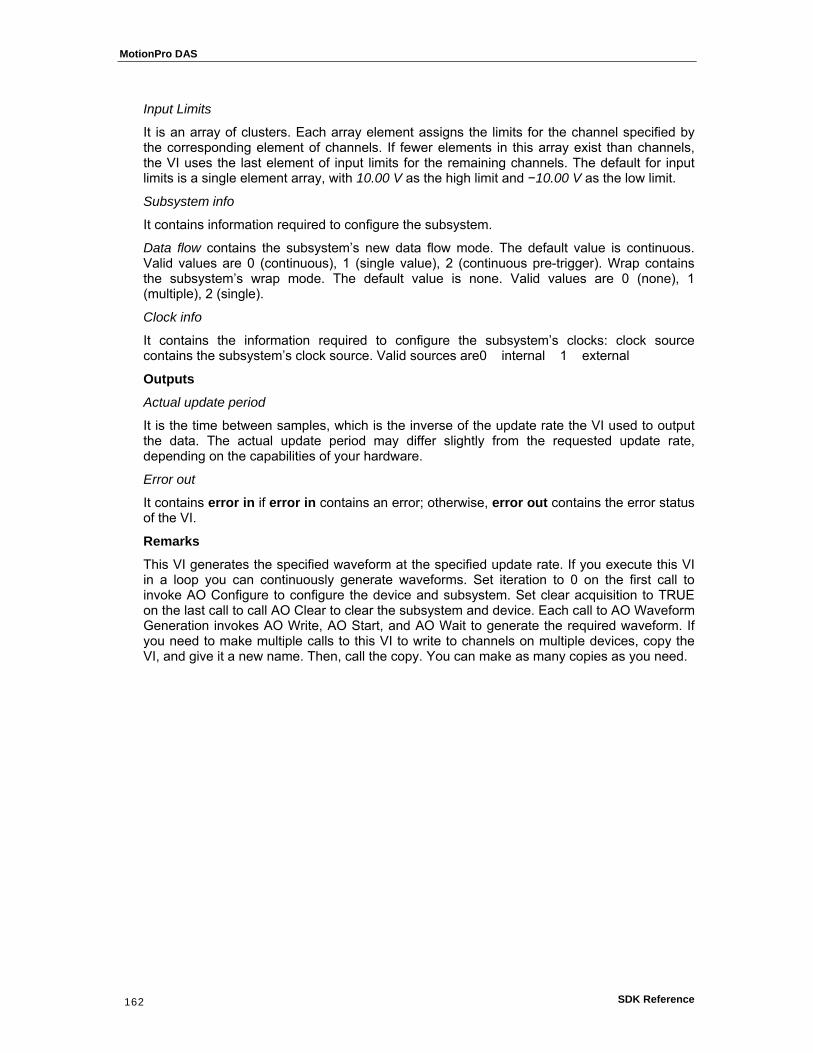
MotionPro DAS
SDK Reference 162
Input Limits
It is an array of clusters. Each array element assigns the limits for the channel specified by the corresponding element of channels. If fewer elements in this array exist than channels, the VI uses the last element of input limits for the remaining channels. The default for input limits is a single element array, with 10.00 V as the high limit and −10.00 V as the low limit.
Subsystem info
It contains information required to configure the subsystem.
Data flow contains the subsystem’s new data flow mode. The default value is continuous. Valid values are 0 (continuous), 1 (single value), 2 (continuous pre-trigger). Wrap contains the subsystem’s wrap mode. The default value is none. Valid values are 0 (none), 1 (multiple), 2 (single).
Clock info
It contains the information required to configure the subsystem’s clocks: clock source contains the subsystem’s clock source. Valid sources are0 internal 1 external
Outputs
Actual update period
It is the time between samples, which is the inverse of the update rate the VI used to output the data. The actual update period may differ slightly from the requested update rate, depending on the capabilities of your hardware.
Error out
It contains error in if error in contains an error; otherwise, error out contains the error status of the VI.
Remarks This VI generates the specified waveform at the specified update rate. If you execute this VI in a loop you can continuously generate waveforms. Set iteration to 0 on the first call to invoke AO Configure to configure the device and subsystem. Set clear acquisition to TRUE on the last call to call AO Clear to clear the subsystem and device. Each call to AO Waveform Generation invokes AO Write, AO Start, and AO Wait to generate the required waveform. If you need to make multiple calls to this VI to write to channels on multiple devices, copy the VI, and give it a new name. Then, call the copy. You can make as many copies as you need.
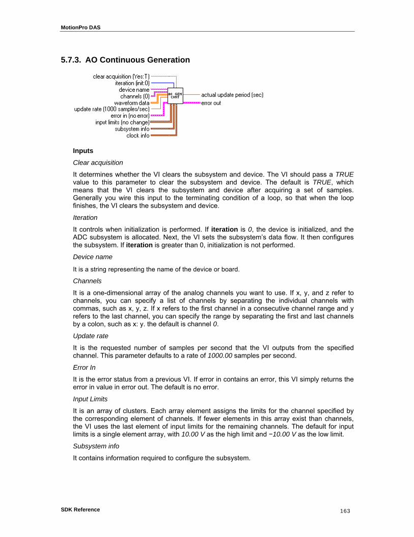
MotionPro DAS
SDK Reference 163
5.7.3. AO Continuous Generation
Inputs
Clear acquisition
It determines whether the VI clears the subsystem and device. The VI should pass a TRUE value to this parameter to clear the subsystem and device. The default is TRUE, which means that the VI clears the subsystem and device after acquiring a set of samples. Generally you wire this input to the terminating condition of a loop, so that when the loop finishes, the VI clears the subsystem and device.
Iteration
It controls when initialization is performed. If iteration is 0, the device is initialized, and the ADC subsystem is allocated. Next, the VI sets the subsystem’s data flow. It then configures the subsystem. If iteration is greater than 0, initialization is not performed.
Device name
It is a string representing the name of the device or board.
Channels
It is a one-dimensional array of the analog channels you want to use. If x, y, and z refer to channels, you can specify a list of channels by separating the individual channels with commas, such as x, y, z. If x refers to the first channel in a consecutive channel range and y refers to the last channel, you can specify the range by separating the first and last channels by a colon, such as x: y. the default is channel 0.
Update rate
It is the requested number of samples per second that the VI outputs from the specified channel. This parameter defaults to a rate of 1000.00 samples per second.
Error In
It is the error status from a previous VI. If error in contains an error, this VI simply returns the error in value in error out. The default is no error.
Input Limits
It is an array of clusters. Each array element assigns the limits for the channel specified by the corresponding element of channels. If fewer elements in this array exist than channels, the VI uses the last element of input limits for the remaining channels. The default for input limits is a single element array, with 10.00 V as the high limit and −10.00 V as the low limit.
Subsystem info
It contains information required to configure the subsystem.

MotionPro DAS
SDK Reference 164
Data flow contains the subsystem’s new data flow mode. The default value is continuous. Valid values are 0 (continuous), 1 (single value), 2 (continuous pre-trigger).
Wrap contains the subsystem’s wrap mode. The default value is none. Valid values are 0 (none), 1 (multiple), 2 (single).
Clock info
It contains the information required to configure the subsystem’s clocks: clock source contains the subsystem’s clock source. Valid sources are 0 (internal), 1 (external).
Outputs
Actual update period
It is the time between updates, which is the inverse of the update rate the VI used to generate the data. The actual update period may differ slightly from the requested update rate, depending on the capabilities of your hardware.
Error out
It contains error in if error in contains an error; otherwise, error out contains the error status of the VI.
Remarks This VI generates continuous, time-sampled output values for a group of channels. Use AO Continuous Generation to output a waveform to a group of channels indefinitely.
If you execute this VI in a loop, you can continuously generate waveforms. Set iteration to 0 on the first call to invoke AO Configure, AO Write and AO Start to configure and start the analog output operation. Set clear acquisition to TRUE on the last call to call AO Clear to clear the subsystem and device.
If you need to make multiple calls to this VI to write to channels on multiple devices, copy the VI, and give it a new name. Then, call the copy. You can make as many copies as you need.
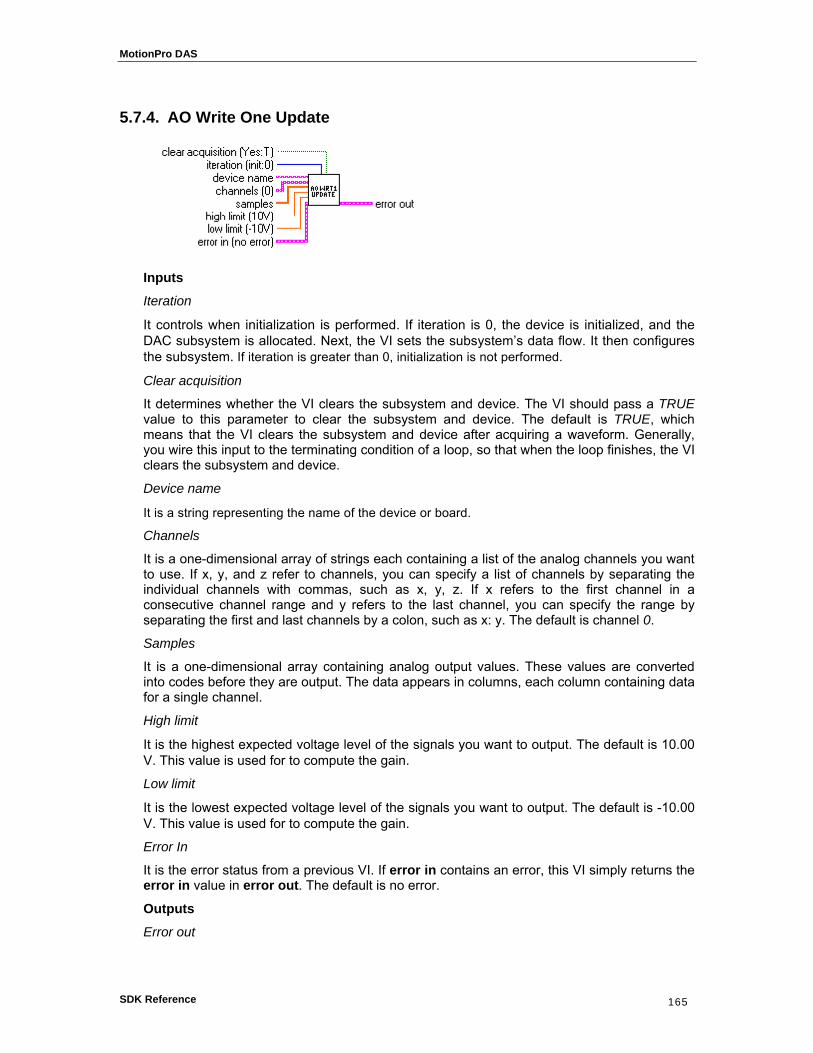
MotionPro DAS
SDK Reference 165
5.7.4. AO Write One Update
Inputs
Iteration
It controls when initialization is performed. If iteration is 0, the device is initialized, and the DAC subsystem is allocated. Next, the VI sets the subsystem’s data flow. It then configures the subsystem. If iteration is greater than 0, initialization is not performed.
Clear acquisition
It determines whether the VI clears the subsystem and device. The VI should pass a TRUE value to this parameter to clear the subsystem and device. The default is TRUE, which means that the VI clears the subsystem and device after acquiring a waveform. Generally, you wire this input to the terminating condition of a loop, so that when the loop finishes, the VI clears the subsystem and device.
Device name
It is a string representing the name of the device or board.
Channels
It is a one-dimensional array of strings each containing a list of the analog channels you want to use. If x, y, and z refer to channels, you can specify a list of channels by separating the individual channels with commas, such as x, y, z. If x refers to the first channel in a consecutive channel range and y refers to the last channel, you can specify the range by separating the first and last channels by a colon, such as x: y. The default is channel 0.
Samples
It is a one-dimensional array containing analog output values. These values are converted into codes before they are output. The data appears in columns, each column containing data for a single channel.
High limit
It is the highest expected voltage level of the signals you want to output. The default is 10.00 V. This value is used for to compute the gain.
Low limit
It is the lowest expected voltage level of the signals you want to output. The default is -10.00 V. This value is used for to compute the gain.
Error In
It is the error status from a previous VI. If error in contains an error, this VI simply returns the error in value in error out. The default is no error.
Outputs
Error out

MotionPro DAS
SDK Reference 166
It contains error in if error in contains an error; otherwise, error out contains the error status of the VI.
Remarks
This VI performs an immediate, non timed update of a group of one or more channels. The samples are converted to codes before the update is performed.
If you execute this VI in a loop, you can continuously write to the channel. Set iteration to 0 on the first call to configure the port and set clear acquisition to TRUE on the last call to clear the subsystem and device.
If you need to make multiple calls to this VI to read channels on multiple devices, copy the VI, and give it a new name. Then, call the copy. You can make as many copies as you need.

MotionPro DAS
SDK Reference 167
55..88.. MMiisscceellllaanneeoouuss VVIIss
5.8.1. Overview
Miscellaneous VIs, which provide common functionalities used by all types of data acquisition subsystems, are the following:
Parse Channel parses all of the channels specified in a channel list string.
Parse Channels parses all of the channels specified in an array of channel lists.
Get Board Selection presents a list of installed data acquisition devices and allows you to select the board you want to use.
Default Board selects the first data acquisition device found on your computer.
Error Handler assembles an error message based on the status of error in.

MotionPro DAS
SDK Reference 168
5.8.2. Parse Channel
Inputs
Channel
It is a string containing a list of the channels you want to use. If x, y, and z refer to channels, you can specify a list of channels by separating the individual channels with commas, such as x, y, z. If x refers to the first channel in a consecutive channel range and y refers to the last channel, you can specify the range by separating the first and last channels by a colon, such as x: y. The default is channel 0.
Error in
It contains the error status from a previous VI. If error in contains an error, this VI simply returns the error in value in error out. The default is no error.
Outputs
Channels
It is a one-dimensional array containing all of the channels parsed from channel in the order they appear in channel. For example, if channel was “1,2,6,1:3” then channels would be a 6-element array containing 1,2,6,1,2,3.
Error out
It contains error in if error in contains an error; otherwise, error out contains the error status of the VI.
Remarks This VI parses all of the channels specified in a channel list string. If the channel list contains an invalid character or character sequence, this VI will return error code 3000.

MotionPro DAS
SDK Reference 169
5.8.3. Parse Channels
Inputs
Channel
It is a one-dimensional array of strings each containing a list of the channels you want to use. If x, y, and z refer to channels, you can specify a list of channels by separating the individual channels with commas, such as x, y, z. If x refers to the first channel in a consecutive channel range and y refers to the last channel, you can specify the range by separating the first and last channels by a colon, such as x: y. The default is channel 0.
Error in
It contains the error status from a previous VI. If error in contains an error, this VI simply returns the error in value in error out. The default is no error.
Outputs
Channels
It is a one-dimensional array containing all of the channels parsed from channel in the order they appear in channel. For example, if channel was “1,2,6,1:3” then channels would be a 6-element array containing 1,2,6,1,2,3.
Error out
It contains error in if error in contains an error; otherwise, error out contains the error status of the VI.
Remarks This VI parses all of the channels specified in an array of channel lists. If the channel list contains an invalid character or character sequence, this VI will return error code 3000.

MotionPro DAS
SDK Reference 170
5.8.4. Get Board Selection
Outputs
Board Selected
It contains the name of the board selected. If you click Cancel, board selected will be an empty string.
Canceled
It is TRUE if you pushed the Cancel button; otherwise, FALSE.
Error out
It contains the VI’s error status.
Remarks This VI presents a list of installed data acquisition devices and allows the selection of one of them. The VI is set up to open its front panel when called and close when complete. The VI is closed when you click either the “OK” or “Cancel” button.

MotionPro DAS
SDK Reference 171
5.8.5. Get Default Board
Outputs
Default Board
It contains the name of the first enumerated board.
Not Found
Not found is TRUE if no board was found or an error occurred
Error out
It contains the VI’s error status.
Remarks This VI returns the name of the first enumerated board on your pc.

MotionPro DAS
SDK Reference 172
5.8.6. Error Handler
Inputs
Type of dialog
It determines what type of dialog box is used to display translated errors.
0 No dialog - Directs the handler not to display the error message.
1 OK message - Causes the handler to display a single OK button dialog box containing the error message. This is the default.
2 Continue or stop message - Displays a two button dialog allowing you to select “Continue” or “Stop”. If “Stop” is selected, the VI calls the LabVIEW Stop VI which aborts VI execution.
Canceled
It is TRUE if you pushed the Cancel button; otherwise, FALSE.
Outputs Message
It contains the error text message that was assembled by the error handler.
Error out
It contains the VI’s error status.
Remarks This VI assembles an error message based on the status of error in. If the status element of error in is TRUE, the VI attempts to translate the code element of error in. A text error message is built based on the translated error text and the source element of error in. If the status element is FALSE, the error handler returns “No Error” as the message text. Depending on the value of type of dialog, a one-button or two-button dialog box may appear containing the message text.

MotionPro DAS
SDK Reference 173
55..99.. EExxaammpplleess VVIIss
5.9.1. Simple AI Sample Channel
The Simple AI Sample Channel example demonstrates how to use the AI Sample Channel VI. This example reads a voltage from a single analog input channel.
5.9.2. Simple AI Sample Channels
The Simple AI Sample Channels example demonstrates how to use the AI Sample Channels VI. This example reads a voltage from the multiple analog input channels specified.
5.9.3. Simple AI Acq Wave
The Simple AI Acq Wave example demonstrates how to use the AI Acquire Waveform VI. This example allows you to acquire a waveform at a specified frequency. Then, the acquired waveform is plotted in a graph.
5.9.4. Simple AI Acq Waves
The Simple AI Acq Waves example demonstrates how to use the AI Acquire Waveforms VI. This example allows you to acquire a waveform at a specified frequency. Then, the acquired waveform is plotted in a graph.
5.9.5. Simple AI Continuous Acq
The Simple AI Continuous Acq example demonstrates how to use the AI Continuous Scan VI. This example acquires continuous waveforms at a specified frequency, and plots the data in a graph.
5.9.6. Simple AO Update Channel
The Simple AO Update Channel example demonstrates how to use the AO Update Channel VI. This VI writes the specified voltage to a single analog output channel.
5.9.7. Simple AO Update Channels
The Simple AO Update Channels example demonstrates how to use the AO Update Channels VI. This VI writes the specified voltage to the analog output channels specified. Each channel receives the same voltage.
5.9.8. Simple AO Gen Wave
The Simple AO Update Channels example demonstrates how to use the AO Update Channels VI. This VI writes the specified voltage to the analog output channels specified. Each channel receives the same voltage.
MotionPro DAS
SDK Reference 174
5.9.9. Simple AO Gen Waves
The Simple AO Gen Waves example demonstrates how to use the AO Generate Waveforms VI. This VI generates a waveform - Sine, Triangle, Square or Saw tooth - at a specified frequency and amplitude. The resulting waveform is output on the specified analog output channels. Each channel receives the same waveform.
5.9.10. Simple AO Continuous Gen
The Simple AO Continuous Gen example demonstrates how to use the AO Continuous Generation VI. This VI generates continuous waveforms - Sine, Triangle, Square or Saw tooth - at a specified frequency and amplitude. The resulting waveforms are output on the specified analog output channels. Each channel receives the same waveform.
MotionPro DAS
SDK Reference 175
66.. DDaattaa AAccqquuiissiittiioonn MMAATTLLAABB™™ IInntteerrffaaccee
66..11.. OOvveerrvviieeww
The MATLAB™ Interface allows the user to operate the Data Acquisition from inside the Mathworks™ MATLAB application. The interface works with MATLAB 6.5 and greater, on Windows 2000/XP Professional. Windows NT is not supported.
The Data Acquisition MATLAB™ Interface includes a ‘MEX’ file for controlling the device (packaged in a library called XSDAML.dll) and some example .m files to show how to use the interface.
Every routine may be called from a MATLAB™ script file in the form:
[output1, output2 ...] = XSDAML [input1, input2 …]
The number of inputs and outputs depends on the function selected. In any function call input1 is the name of the requested command (for ex. ‘EnumDevices’) and output1 is the result of the operation (0 = SUCCESS, otherwise ERROR).
More details on the commands syntax may be retrieved by typing “help XSDAML” at MATLAB command prompt or opening the file XSDAML.m with a text editor.
The MATLAB interface reflects the SDK Application Program Interface (see the Data Acquisition SDK reference section) with a few exceptions. The MATLAB interface and examples are listed below.

MotionPro DAS
SDK Reference 176
66..22.. IInniittiiaalliizzaattiioonn FFuunnccttiioonnss
6.2.1. Overview: Initialization functions
Initialization functions allow the user to initialize the Data Acquisition device, enumerate the available devices, open and close them.
GetVersion retrieves the driver version.
EnumDevices enumerates the IDs of the Data Acquisition Devices connected to the computer.
OpenDevice opens a Data Acquisition device.
CloseDevice closes a Data Acquisition device previously open.
GetHardwareError returns last encountered vendor specific error and the description string.

MotionPro DAS
SDK Reference 177
6.2.2. GetVersion
[strVersion] = XSDAML (‘GetVersion’)
Inputs
None
Outputs
strVersion
Specifies the driver version string (for example, ‘1.00’)
Remarks
This function must be called to retrieve the Data Acquisition MATLAB interface version string.
See also:

MotionPro DAS
SDK Reference 178
6.2.3. EnumDevices
[nResult, nItems, daArray] = XSDAML (‘EnumDevices’)
Inputs
None
Outputs
nResult
Specifies the return error code of the function (0 if the function is successful, otherwise not 0)
nItems
Specifies the number of detected devices
daArray
Specifies the array containing the IDs of the detected devices
Remarks
The routine enumerates the active devices and returns an array filled with the detected devices IDs. This routine must be called before OpenDevice to find out which devices are available. The nItems variable contains the number of detected devices. If any error occurs during the devices enumeration, the nResult variable contains an error code.
See also: OpenDevice

MotionPro DAS
SDK Reference 179
6.2.4. OpenDevice
[nResult, nDeviceId] = XSDAML (‘OpenDevice’, nInputId )
Inputs
nInputId
Specifies the ID of the device to be opened, or 0 for the first available device
Outputs
nResult
Specifies the return error code of the function (0 if the function is successful, otherwise not 0)
nDeviceId
Specifies the ID of the opened device
Remarks
The routine opens the device whose ID is in the variable nInputId. The value can be retrieved by calling the EnumDevices enumeration function. The user may supply a specific device ID or 0: in this case the first available device is opened. If any error occurs during the device opening, the routine returns an error code in the nResult variable, otherwise it returns 0. The function also returns the device Id.
See also: CloseDevice

MotionPro DAS
SDK Reference 180
6.2.5. CloseDevice
[nResult] = XSDAML (‘CloseDevice’, nDeviceId)
Inputs
nDeviceId
Specifies the ID of the device to be closed
Outputs
nResult
Specifies the return error code of the function (0 if the function is successful, otherwise not 0)
Remarks
This function closes a device previously open. If any error occurs during the operation, the routine returns an error code in the nResult variable, otherwise it returns 0.
See also: OpenDevice

MotionPro DAS
SDK Reference 181
6.2.6. OpenSubSystem
[nResult] = XSDAML (‘OpenSubSystem’, nSubId)
Inputs
nSubId
Specifies the ID of the subsystem to be opened. See the XsdaApi.h in the SDK for a list of all the available subsystem IDs.
Outputs
nResult
Specifies the return error code of the function (0 if the function is successful, otherwise not 0)
Remarks
This function opens the subsystem whose ID is in the variable nSubId. If any error occurs during the device opening, the routine returns an error code in the nResult variable, otherwise it returns 0.
See also: CloseSubSystem

MotionPro DAS
SDK Reference 182
6.2.7. CloseSubSystem
[nResult] = XSDAML (‘CloseSubSystem’, nSubId)
Inputs
nSubId
It specifies the ID of the subsystem to be closed. See the XsdaApi.h in the SDK for a list of all the available subsystem IDs.
Outputs
nResult
Specifies the return error code of the function (0 if the function is successful, otherwise not 0)
Remarks
This function closes a device previously open. If any error occurs during the operation, the routine returns an error code in the nResult variable, otherwise it returns 0.
See also: OpenSubSystem

MotionPro DAS
SDK Reference 183
6.2.8. GetHardwareError
[nResult , nError, szErrorStr] = XSDAML (‘GetHardwareError’, nDeviceId)
Inputs
nDeviceId
Specifies the ID of the device
Outputs
nResult
Specifies the return error code of the function (0 if the function is successful, otherwise not 0)
nError
Specifies the error ID
szErrorStr
Specifies the zero terminated string with error description
Remarks
This function returns last encountered vendor specific error and the description string.
See also:

MotionPro DAS
SDK Reference 184
66..33.. CCoonnffiigguurraattiioonn ffuunnccttiioonnss
6.3.1. Overview: Configuration functions
Configuration functions allow the user to read information from the device, read configuration parameters from the device and write them to the device.
GetDeviceInfo reads information from the device, such as device model, firmware version, etc.
GetParameter reads a single specific parameter from the configuration.
SetParameter writes a single specific parameter to the configuration.
RefreshSettings downloads the updated configuration to the device and activates it.

MotionPro DAS
SDK Reference 185
6.3.2. GetDeviceInfo
[nResult, nInfoValueLo, nInfoValueHi] = XSDAML (‘GetDeviceInfo’, nDeviceId, nInfoKey)
Inputs
nDeviceId
Specifies a valid device ID
nInfoKey
Specifies which parameter the function has to return
Outputs
nResult
Specifies the return error code of the function (0 if the function is successful, otherwise not 0)
nInfoValueLo
Specifies the low part of the value of the info parameter
nInfoValueHi
Specifies the high part of the value of the info parameter
Remarks
This function returns device specific information, such as device type or version numbers, generally state-independent information. See the Appendix B for a list of all the available nInfoKey values.
See also: GetParameter

MotionPro DAS
SDK Reference 186
6.3.3. GetParameter
[nResult, nValue] = XSDAML (‘GetParameter’, nDeviceId, nSubId, nParamKey, nSubParamKey)
Inputs
nDeviceId
Specifies a valid device ID
nSubId
Specifies the ID of the subsystem.
nParamKey
Specifies the index of the parameter
nSubParamKey
Specifies the index of the sub-parameter
Outputs
nResult
Specifies the return error code of the function (0 if the function is successful, otherwise not 0)
nValue
Specifies the current value of the parameter
Remarks
This function reads a specific parameter from the current configuration and returns its value. The parameter key is one of the input parameters. A list of the parameters constants is available in Appendix C. If any error occurs during the operation, the routine returns an error code in the nResult variable, otherwise it returns 0.
See also: SetParameter, RefreshSettings

MotionPro DAS
SDK Reference 187
6.3.4. SetParameter
[nResult] = XSDAML (‘SetParameter’, nDeviceId, nSubId, nParamKey, nSubParamKey, nValue)
Inputs
nDeviceId
Specifies a valid device ID
nSubId
Specifies the ID of the subsystem.
nParamKey
Specifies the index of the parameter
nSubParamKey
Specifies the index of the sub-parameter
nValue
Specifies the value to set
Outputs
nResult
Specifies the return error code of the function (0 if the function is successful, otherwise not 0)
Remarks
This function reads a specific parameter from the current configuration and returns its value. The parameter key is one of the input parameters. A list of the parameters constants is available in Appendix C. If any error occurs during the operation, the routine returns an error code in the nResult variable, otherwise it returns 0. The user may call the SetParameter function several times to set different parameters, and then call the RefreshSettings to download the configuration to the device.
See also: GetParameter, RefreshSettings
MotionPro DAS
SDK Reference 188
6.3.5. RefreshSettings
[nResult] = XSDAML (‘RefreshSettings’, nDeviceId, nSubId)
Inputs
nDeviceId
Specifies a valid device ID
nSubId
Specifies the ID of the subsystem.
Outputs
nResult
Specifies the return error code of the function (0 if the function is successful, otherwise not 0)
Remarks
This function downloads the configuration to the device and activates it. If any error occurs during the operation, the routine returns an error code in the nResult variable, otherwise it returns 0. The user may call the SetParameter function several times to set different parameters, and then call the RefreshSettings to download the configuration to the device.
See also: GetParameter, SetParameter
MotionPro DAS
SDK Reference 189
66..44.. OOppeerraattiioonn FFuunnccttiioonnss
6.4.1. Overview: Outputs enable/disable Functions
Once you have set the parameters of a subsystem, you can use the following Operation functions.
GetSinglValue reads a single input value from the specified subsystem channel.
SetSingleValue outputs a value on the subsystem channel specified.
Start causes the subsystem specified by nSubId to start the operation for which it was configured.
Stop causes the subsystem specified by nSubId to stop the current operation.
Abort directs the subsystem specified by nSubId to stop its current operation immediately and to return to the ready state.
Reset causes the subsystem specified by nSubId to immediately terminate any current operation and place itself into a known default state ready to receive new configuration information.
GetSSCounts gets the number of messages received by a subsystem.
GetBuffer retrieves a buffer from the done queue of the subsystem specified
PutBuffer places the buffer specified onto the ready queue of the subsystem specified.
FlushBuffers transfers all buffers on the ready and in-process queues of the subsystem specified to the done queue.
FlushFromBufferInprocess copies all valid samples, up to the number specified, from the buffer currently in the in-process queue of the subsystem specified to the buffer specified.

MotionPro DAS
SDK Reference 190
6.4.2. GetSingleValue
[nResult, nValue] = XSDAML (‘GetSingleValue’, nDeviceId, nSubId, nChannel, nGain)
Inputs
nDeviceId
Specifies the ID of the device
nSubId
Specifies the subsystem ID
nChannel
Specifies the input channel to use
nGain
Specifies the gain settings of the input stage (0 = 1X, 1 = 2X, 2 = 4X, 3 = 8X)
Outputs
nResult
Specifies the return error code of the function (0 if the function is successful, otherwise not 0)
nValue
Specifies the subsystem's input value (only the the least 16 less significant bits are valid)
Remarks
This function reads a single input value from the specified subsystem channel
See also: PutSingleValue

MotionPro DAS
SDK Reference 191
6.4.3. PutSingleValue
[nResult] = XSDAML (‘PutSingleValue’, nDeviceId, nSubId, nChannel, nGain, nValue)
Inputs
nDeviceId
Specifies the ID of the device
nSubId
Specifies the subsystem ID
nChannel
Specifies the output channel to use
nGain
Specifies the gain settings of the output stage. The only accepted value is 0 = 1X
nValue
Specifies the subsystem's output value (only the the least 16 less significant bits are valid)
Outputs
nResult
Specifies the return error code of the function (0 if the function is successful, otherwise not 0)
Remarks
This function reads a single input value from the specified subsystem channel
See also: GetSingleValue

MotionPro DAS
SDK Reference 192
6.4.4. Start
[nResult] = XSDAML (‘Start’, nDeviceId, nSubId)
Inputs
nDeviceId
Specifies the ID of the
nSubId
Specifies the subsystem ID
Outputs
nResult
Specifies the return error code of the function (0 if the function is successful, otherwise not 0)
Remarks
This function causes the subsystem specified by nSubId to start the operation for which it was configured
See also: Stop

MotionPro DAS
SDK Reference 193
6.4.5. Stop
[nResult] = XSDAML (‘Stop’, nDeviceId, nSubId)
Inputs
nDeviceId
Specifies the ID of the device
nSubId
Specifies the subsystem ID
Outputs
nResult
Specifies the return error code of the function (0 if the function is successful, otherwise not 0)
Remarks
This function causes the subsystem specified by nSubId to stop the current operation
See also: Start

MotionPro DAS
SDK Reference 194
6.4.6. Abort
[nResult] = XSDAML (‘Abort’, nDeviceId, nSubId)
Inputs
nDeviceId
Specifies the ID of the device
nSubId
Specifies the subsystem ID
Outputs
nResult
Specifies the return error code of the function (0 if the function is successful, otherwise not 0)
Remarks
This function directs the subsystem specified by nSubId to stop its current operation immediately and to return to the ready state.
See also: Start

MotionPro DAS
SDK Reference 195
6.4.7. Reset
[nResult] = XSDAML (‘Reset’, nDeviceId, nSubId)
Inputs
nDeviceId
Specifies the ID of the device
nSubId
Specifies the subsystem ID
Outputs
nResult
Specifies the return error code of the function (0 if the function is successful, otherwise not 0)
Remarks
This function causes the subsystem specified by nSubId to immediately terminate any current operation and place itself into a known default state ready to receive new configuration information.
See also: Start

MotionPro DAS
SDK Reference 196
6.4.8. GetSSCounts
[ nResult, daSSCounts] = XSDAML (‘GetSSCounts’, nDeviceId, nSubId)
Inputs
nDeviceId
Specifies the ID of the device
nSubId
Specifies the subsystem ID
Outputs
nResult
Specifies the return error code of the function (0 if the function is successful, otherwise not 0)
daSSCounts
Specifies the UINT32 one dimensional array where the messages counters are stored. The meaning of every field of this array is the following:
daSSCounts(1) contains the number of buffer reused messages received.
daSSCounts(2) contains the number of buffer done messages received.
daSSCounts(3) contains the number of buffer pre-trigger done messages received.
daSSCounts(4) contains the number of buffer queue done messages received.
daSSCounts(5) contains the number of buffer queue stopped messages received.
daSSCounts(6) contains the number of buffer trigger error messages received.
daSSCounts(7) contains the number of buffer overrun error messages received.
daSSCounts(8) contains the number of buffer underrun error messages received.
Remarks
This function gets the number of messages received by a subsystem. These messages are counted and retained until they are read. Once read, the message counts are reset to zero.
See also: Start, Stop

MotionPro DAS
SDK Reference 197
6.4.9. GetBuffer
[nResult, hBuffer] = XSDAML (‘GetBuffer’, nDeviceId, nSubId)
Inputs
nDeviceId
Specifies the ID of the device
nSubId
Specifies the subsystem ID
Outputs
nResult
Specifies the return error code of the function (0 if the function is successful, otherwise not 0)
hBuffer
Specifies the returned buffer handle.
Remarks
This function retrieves a buffer from the done queue of the subsystem specified by nSubId so that the buffer can be processed and/or put back on the ready queue. The buffer handle is returned in hBuffer
See also: PutBuffer
MotionPro DAS
SDK Reference 198
6.4.10. PutBuffer
[nResult] = XSDAML (‘GetBuffer’, nDeviceId, nSubId ,hBuffer)
Inputs
nDeviceId
Specifies the ID of the device
nSubId
Specifies the subsystem ID
hBuffer
Specifies the buffer handle.
Outputs
nResult
Specifies the return error code of the function (0 if the function is successful, otherwise not 0)
Remarks
This function places the buffer specified by hBuffer onto the ready queue of the subsystem specified by nSubId.
See also: GetBuffer
MotionPro DAS
SDK Reference 199
6.4.11. FlushBuffers
[nResult] = XSDAML (‘FlushBuffers’, nDeviceId, nSubId)
Inputs
nDeviceId
Specifies the ID of the device
nSubId
Specifies the subsystem ID
Outputs
nResult
Specifies the return error code of the function (0 if the function is successful, otherwise not 0)
Remarks
This function transfers all buffers on the ready and in-process queues of the subsystem specified by nSubId to the done queue.
See also: FlushFromBufferInprocess
MotionPro DAS
SDK Reference 200
6.4.12. FlushFromBufferInprocess
[nResult] = XSDAML ( ‘FlushFromBufferInprocess’, nDeviceId, nSubId, hBuf, nSamples)
Inputs
nDeviceId
Specifies the ID of the device
nSubId
Specifies the subsystem ID
hBuf
Specifies the buffer handle
nSamples
Specifies the number of samples to copy
Outputs
nResult
Specifies the return error code of the function (0 if the function is successful, otherwise not 0)
Remarks
This function copies all valid samples, up to the number specified by nSamples, from the buffer currently in the in-process queue of the subsystem specified by nSubId to the buffer specified by hBuf. It also sets the logical size of the buffer hBuf to the number of samples copied (see DataSetValidSamples). The buffer is then immediately placed on the done queue, and a DA_WM_BUFFER_DONE message is generated.
See also: FlushBuffers

MotionPro DAS
SDK Reference 201
66..55.. BBuuffffeerr MMaannaaggeemmeenntt FFuunnccttiioonnss
6.5.1. Overview: Buffer Management Functions
The buffer management functions provide a set of buffer management facilities. When a buffer is created, a buffer handle is returned. This handle is used in all subsequent buffer manipulation.
DataAllocBuffer allocates a data buffer.
DataFreeBuffer delete a buffer.
GetValidSamples gives the number of valid samples a buffer can hold.
SetValidSamples sets the number of valid samples the buffer can hold.
GetMaxSamples gives the maximum number of valid samples that a buffer can hold.
CopyFromBuffer allocates and returns in a local 16 bit word (unsigned short) one dimensional array the content of the specified buffer.
CopyToBuffer copies to the specified buffer the content of the local 16 bit word (unsigned short) one dimensional array.

MotionPro DAS
SDK Reference 202
6.5.2. DataAllocBuffer
[nResult, hBuffer] = XSDAML (‘DataAllocBuffer’, nDeviceId, nSize)
Inputs
nDeviceId
Specifies a valid device ID
nSize
Specifies the size of the buffer, in samples
Outputs
nResult
Specifies the return error code of the function (0 if the function is successful, otherwise not 0)
hBuffer
Specifies the returned buffer handle
Remarks
This function allocates a data buffer, where nSize represents the size of the buffer. The buffer's handle is returned in hBuffer.
See also: DataFreeBuffer

MotionPro DAS
SDK Reference 203
6.5.3. DataFreeBuffer
[nResult] = XSDAML (‘DataAllocBuffer’, nDeviceId, hBuffer)
Inputs
nDeviceId
Specifies a valid device ID
nSize
Specifies the size of the buffer, in samples
Outputs
nResult
Specifies the return error code of the function (0 if the function is successful, otherwise not 0)
hBuffer
Specifies the returned buffer handle
Remarks
This function deletes the buffer associated with hBuffer.
See also: DataAllocBuffer

MotionPro DAS
SDK Reference 204
6.5.4. GetValidSamples
[nResult, nSamples] = XSDAML (‘GetValidSamples’, nDeviceId, hBuffer)
Inputs
nDeviceId
Specifies a valid device ID
hBuffer
Specifies the buffer handle
Outputs
nResult
Specifies the return error code of the function (0 if the function is successful, otherwise not 0)
nSamples
Specifies the number of valid samples
Remarks
This function returns, in nSamples, the number of valid samples a buffer can hold (always less than or equal to the physical size). This value corresponds to the logical size of the buffer (in bytes) divided by the data width (that is 2)
See also: SetValidSamples

MotionPro DAS
SDK Reference 205
6.5.5. SetValidSamples
[nResult] = XSDAML (‘SetValidSamples’, nDeviceId, hBuffer, nSamples)
Inputs
nDeviceId
Specifies a valid device ID
hBuffer
Specifies the buffer handle
nSamples
Specifies the number of valid samples
Outputs
nResult
Specifies the return error code of the function (0 if the function is successful, otherwise not 0)
Remarks
This function sets, in nSamples, the number of valid samples the buffer specified by hBuffer can hold (always less than or equal to physical size). This value corresponds to the physical size of the buffer (in bytes) divided by the data width (that is 2).
See also: GetValidSamples
MotionPro DAS
SDK Reference 206
6.5.6. GetMaxSamples
[nResult, nMax ] = XSDAML (‘GetMaxSamples’, nDeviceId, hBuffer)
Inputs
nDeviceId
Specifies a valid device ID
hBuffer
Specifies the buffer handle
Outputs
nResult
Specifies the return error code of the function (0 if the function is successful, otherwise not 0)
nMax
Specifies the maximum number of samples
Remarks
This function returns in nMax the maximum number of samples the specified buffer can hold. This value corresponds to the physical size of the buffer (in bytes) divided by the data width (that is 2).
See also: GetValidSamples
MotionPro DAS
SDK Reference 207
6.5.7. CopyFromBuffer
[nResult, pwBuffer ] = XSDAML (‘CopyFromBuffer’, nDeviceId, hBuffer)
Inputs
nDeviceId
Specifies a valid device ID
hBuffer
Specifies the buffer handle
Outputs
nResult
Specifies the return error code of the function (0 if the function is successful, otherwise not 0)
pwBuffer
Specifies the UINT16 one dimensional array
Remarks
This function allocates and returns in the UINT16 one dimensional array pwBuffer, the content of the buffer hBuffer.
See also: CopyToBuffer
MotionPro DAS
SDK Reference 208
6.5.8. CopyToBuffer
[nResult] = XSDAML (‘CopyToBuffer’, nDeviceId, hBuffer, pwBuffer)
Inputs
nDeviceId
Specifies a valid device ID
hBuffer
Specifies the buffer handle
pwBuffer
Specifies the 16 bit word (unsigned short) one dimensional array
Outputs
nResult
Specifies the return error code of the function (0 if the function is successful, otherwise not 0)
Remarks
This function copies to buffer hBuffer the content of the 16 bit word (unsigned short) one dimensional array pwBuffer.
See also: CopyFromBuffer

MotionPro DAS
SDK Reference 209
66..66.. HHooww ttoo uussee tthhee IInntteerrffaaccee ffuunnccttiioonnss
6.6.1. Opening and closing a device and subsystem
A device and a subsystem must be opened before using its functions and then they must be closed. To open a specific device you have to supply to the “OpenDevice” function the unique ID of that device. You may also supply 0 to open the first available device. To obtain the list of all available devices you may call the “EnumDevices” function. To open a specific subsystem you have to supply to the “OpenSubSystem” function the subsystem ID (0 for Analog Input, 1 for Analog Output).
6.6.2. Configuring a subsystem
Before configuring a subsystem, several calls to the “SetParameter” function may be done. When the parameters have been set, a call to the “RefreshSettings” function downloads the new configuration activates it. If you want to read a parameter value you may call the “GetParameter” function. Once you have specified a subsystem, you may configure the subsystem and perform a data acquisition operation, as described in the following section.
6.6.3. Data acquisition
The simplest way to acquire data from a single channel is to specify the channel for a single-value operation (setting Data Flow to Single Value with “SetParameter”) and acquire (using “GetSingleValue”) a single sample. To continuously acquiring data you need to set Data Flow to Continuous with “SetParameter”, allocate buffers with “DataAllocBuffer” and put them on the ready queue using “PutBuffer”. Then you may start the acquisition using “Start” with Analog Input subsystem. When you want to stop the acquisition call “Stop” or “Abort”, and free the allocate buffers using “FlushBuffers”, “GetBuffer” and “DataFreeBuffer”.
6.6.4. Waveform generation
The simplest way to output data to a single channel is to specify the channel for a single-value operation (setting Data Flow to Single Value with “SetParameter”) and outputs (using “SetSingleValue”) a single data. To output continuously a waveform the easiest way it is to set Data Flow to Continuous, and Wrap Mode to Waveform using “SetParameter”. Then allocate a buffer using “DataAllocBuffer”, get the buffer array using “CopyFromBuffer”, insert in the array the waveform data and then call “CopyToBuffer” and “PutBuffer” to put it on the ready queue. Then you may call “Start” to output the waveform. When you want to stop the waveform output, call “Stop” or “Abort”, and free the buffer by using “DataFreeBuffer”.
6.6.5. Error handling
The Data Acquisition MATLAB interface returns the same error codes displayed in the Appendix D.

MotionPro DAS
SDK Reference 210
66..77.. EExxaammpplleess
6.7.1. EnumEx
This example shows how to obtain the list of all available devices.
6.7.2. InfoEx
This example shows how to obtain some information from a device.
6.7.3. ReadParmEx
This example shows how to read specific parameter from a device.
6.7.4. SvAdcEx
This example shows how to execute a single value ADC operation.
6.7.5. SvDacEx
This example shows how to execute a single value DAC operation.
6.7.6. ContAdcEx
This example shows how to execute a continuous ADC operation.
6.7.7. ContDacEx
This example shows how to execute a continuous DAC operation.
6.7.8. AdvAdcEx
This example shows how to acquire signals and show the waveform. You can select the channel to acquire from, and other parameters as “Wrap Mode”, “Trigger Source”, “sampling Rate”, etc.
6.7.9. AdvDacEx
This example shows how to generate a waveform (Sine or Square) at a specified frequency. The resulting waveform is output on the selected analog output channel.

MotionPro DAS
SDK Reference 211
77.. AAppppeennddiixx
77..11.. AAppppeennddiixx AA -- RReettuurrnn CCooddeess
The following table shows the values of the codes returned by the Data Acquisition APIs. The values can be found in the XsdaAPI.h header file in the Include subdirectory.
Code Value Notes
DA_SUCCESS 0 OK – No errors DA_E_GENERIC_ERROR 1 Generic Error DA_E_NOT_SUPPORTED 2 The function is not supported for this device DA_E_INVALID_VALUE 3 Invalid parameter value DA_E_INVALID_HANDLE 5 Invalid DA_HANDLE handle DA_E_INVALID_DEV_ID 6 Invalid device id used in DaOpenDevice. The ID is
retrieved calling the DaEnumDevices routine DA_E_INVALID_ARGUMENTS 7 Invalid function arguments DA_E_READONLY 8 The parameter is read-only and cannot be modified DA_E_DEV_ALREADY_OPEN 9 The device is already open. DA_E_HARDWARE_FAULT 10 Hardware error. To retrieve the hardware error code
call the DaGetHardwareError routine.

MotionPro DAS
SDK Reference 212
77..22.. AAppppeennddiixx BB –– IInnffoorrmmaattiioonn PPaarraammeetteerrss
The following table shows the values and a brief description of the parameters that can be read calling the DaGetDeviceInfo routine. The numeric values of the parameters can be found in the XsdaAPI.h header file in the Include subdirectory.
Parameter Description
DAI_DEVICE_MODEL Device Model ( see DA_DEV_MODEL) DAI_DEVICE_ID Device ID (see DA_ENUMITEM structure) DAI_FW_VERSION Firmware version DAI_SERIAL The device serial number (10 decimal digits value) DAI_REVISION The Data Acquisition Board hardware revision (A, B, C, D, etc.)
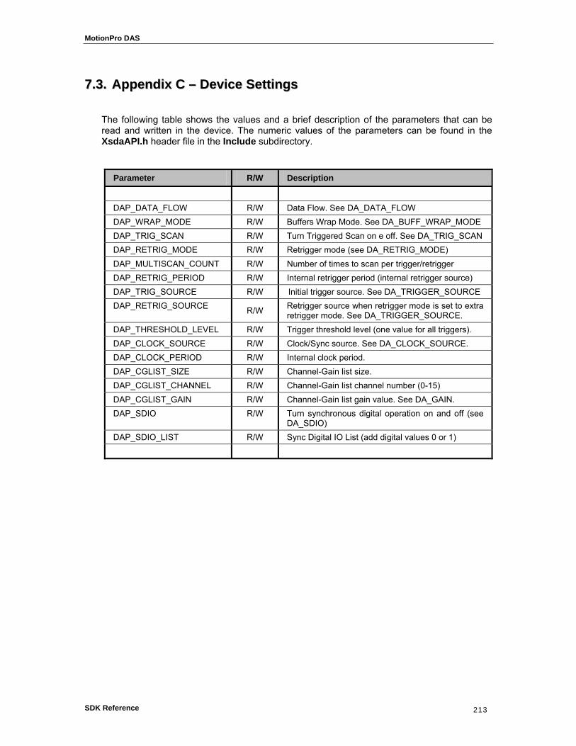
MotionPro DAS
SDK Reference 213
77..33.. AAppppeennddiixx CC –– DDeevviiccee SSeettttiinnggss
The following table shows the values and a brief description of the parameters that can be read and written in the device. The numeric values of the parameters can be found in the XsdaAPI.h header file in the Include subdirectory.
Parameter R/W Description
DAP_DATA_FLOW R/W Data Flow. See DA_DATA_FLOW DAP_WRAP_MODE R/W Buffers Wrap Mode. See DA_BUFF_WRAP_MODE DAP_TRIG_SCAN R/W Turn Triggered Scan on e off. See DA_TRIG_SCAN DAP_RETRIG_MODE R/W Retrigger mode (see DA_RETRIG_MODE) DAP_MULTISCAN_COUNT R/W Number of times to scan per trigger/retrigger DAP_RETRIG_PERIOD R/W Internal retrigger period (internal retrigger source) DAP_TRIG_SOURCE R/W Initial trigger source. See DA_TRIGGER_SOURCE DAP_RETRIG_SOURCE R/W Retrigger source when retrigger mode is set to extra
retrigger mode. See DA_TRIGGER_SOURCE. DAP_THRESHOLD_LEVEL R/W Trigger threshold level (one value for all triggers). DAP_CLOCK_SOURCE R/W Clock/Sync source. See DA_CLOCK_SOURCE. DAP_CLOCK_PERIOD R/W Internal clock period. DAP_CGLIST_SIZE R/W Channel-Gain list size. DAP_CGLIST_CHANNEL R/W Channel-Gain list channel number (0-15) DAP_CGLIST_GAIN R/W Channel-Gain list gain value. See DA_GAIN. DAP_SDIO R/W Turn synchronous digital operation on and off (see
DA_SDIO) DAP_SDIO_LIST R/W Sync Digital IO List (add digital values 0 or 1)

MotionPro DAS
SDK Reference 214
77..44.. AAppppeennddiixx DD –– LLaabbVVIIEEWW // MMAATTLLAABB EErrrroorr CCooddeess
This appendix describes the error codes used in the LabVIEW error cluster and in the MATLAB interface.
Error Code Description
1 Generic error 2 Function is not supported for this device 3 Invalid parameter value 5 Invalid handle 6 Invalid device ID 7 Invalid function argument 8 The parameter is red only 9 The device is already open 10 Hardware error
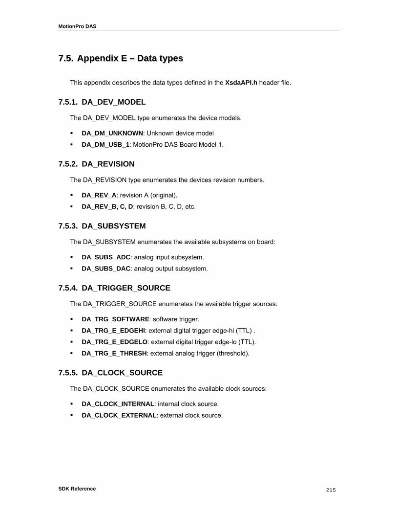
MotionPro DAS
SDK Reference 215
77..55.. AAppppeennddiixx EE –– DDaattaa ttyyppeess
This appendix describes the data types defined in the XsdaAPI.h header file.
7.5.1. DA_DEV_MODEL
The DA_DEV_MODEL type enumerates the device models.
DA_DM_UNKNOWN: Unknown device model
DA_DM_USB_1: MotionPro DAS Board Model 1.
7.5.2. DA_REVISION
The DA_REVISION type enumerates the devices revision numbers.
DA_REV_A: revision A (original).
DA_REV_B, C, D: revision B, C, D, etc.
7.5.3. DA_SUBSYSTEM
The DA_SUBSYSTEM enumerates the available subsystems on board:
DA_SUBS_ADC: analog input subsystem.
DA_SUBS_DAC: analog output subsystem.
7.5.4. DA_TRIGGER_SOURCE
The DA_TRIGGER_SOURCE enumerates the available trigger sources:
DA_TRG_SOFTWARE: software trigger.
DA_TRG_E_EDGEHI: external digital trigger edge-hi (TTL) .
DA_TRG_E_EDGELO: external digital trigger edge-lo (TTL).
DA_TRG_E_THRESH: external analog trigger (threshold).
7.5.5. DA_CLOCK_SOURCE
The DA_CLOCK_SOURCE enumerates the available clock sources:
DA_CLOCK_INTERNAL: internal clock source.
DA_CLOCK_EXTERNAL: external clock source.

MotionPro DAS
SDK Reference 216
7.5.6. DA_DATA_FLOW
The DA_DATA_FLOW enumerates available data flow types:
DA_DF_CONTINUOUS: continuous data flow (input/output).
DA_DF_SINGLEVALUE: single value data flow (input/output).
7.5.7. DA_BUFF_WRAP_MODE
The DA_BUFF_WRAP_MODE enumerates wrap mode types:
DA_WRP_NONE: no wrap – fill/empty buffers once.
DA_WRP_MULTIPLE: fill/empty all buffers continuously.
DA_WRP_SINGLE: fill/empty one buffer continuously.
7.5.8. DA_BUFF_QUEUE
The DA_BUFF_QUEUE enumerates the queue types:
DA_BQ_READY: queue of ready buffers.
DA_BQ_DONE: queue of done buffers.
DA_BQ_IN_PROCESS: queue of buffers in process.
7.5.9. DA_RETRIG_MODE
The DA_RETRIG_MODE enumerates the available retrigger modes.
DA_RETRIG_INTERNAL: internal retrigger.
DA_RETRIG_SCAN_PER_TRIG: retrigger is initial trigger source.
DA_RETRIG_EXTRA: retrigger is configured by DAP_RETRIG_SOURCE.
7.5.10. DA_TRIG_SCAN
The DA_TRIG_SCAN enumerates the trigger scan states.
DA_TS_OFF: triggered scan disabled.
DA_TS_ON: triggered scan enabled.
7.5.11. DA_GAIN
The DA_GAIN enumerates the available gain values:
DA_GAIN_1X: gain is 1X.
DA_GAIN_2X: gain is 2X.
DA_GAIN_4X: gain is 4X.
DA_GAIN_8X: gain is 8X.

MotionPro DAS
SDK Reference 217
7.5.12. DA_ATTRIBUTE
The DA_ATTRIBUTE enumerates the attribute types:
DA_ATTR_MIN: minimum value.
DA_ATTR_MAX: maximum value.
DA_ATTR_DEFAULT: the default value.
DA_ATTR_READONLY: read only attribute.
7.5.13. DA_ERROR
The DA_ERROR enumerates the return codes. See Appendix A.
7.5.14. DA_INFO
The DA_INFO enumerates the device information index. See Appendix B.
7.5.15. DA_PARAM
The DA_PARAM enumerates the device parameters. See Appendix C.

MotionPro DAS
SDK Reference 218
77..66.. AAppppeennddiixx FF –– SSttrruuccttuurreess
This appendix describes the structures defined in the XsdaAPI.h header file.
7.6.1. DA_ENUMITEM
The DA_ENUMITEM structure contains information about a device. It must be used in the device enumeration procedure with the DaEnumDevices routine.
typedef struct { unsigned long cbSize; char szDeviceName[64]; unsigned long nDeviceModel; unsigned long nDeviceId; unsigned long nSerial; unsigned long nRevision; unsigned long nFWVersion; unsigned long bIsOpen; } DA_ENUMITEM, *PDA_ENUMITEM;
Members
cbSize
It specifies the size of the structure.
szDeviceName
It specifies the board’s name.
nDeviceModel
It specifies the device model.
nDeviceId
It specifies the ID which identifies a device among others. The user must use this id to open the device with DaOpenDevice.
nSerial
It specifies the device serial number (10 decimal digits value).
nRevision
It specifies the device hardware revision number (A, B, C, etc.).
nFWVersion
It specifies the device firmware version.
bIsOpen
It specifies whether the device is currently open or not.

MotionPro DAS
SDK Reference 219
7.6.2. DA_AsyncCallback
The DA_AsyncCallback is the prototype of the callback function passed to the DaSetNotificationProcedure routine. The callback is called by the driver when information messages are sent for the selected subsystem.
typedef void (XSDAAPI *DA_AsyncCallback) ( unsigned int uiMsg, WPARAM wParam, LPARAM lParam );
Members
uiMsg
The returned message.
wParam
The subsystem ID.
lParam
The user value passed to DaSetNotificationProcedure.