Data Networking Concepts
54
© Peter R. Egli 2015 1/54 Rev. 1.00 indigoo.com Data Networking Concepts Peter R. Egli INDIGOO.COM OVERVIEW OF IMPORTANT CONCEPTS AND TERMS USED IN DATA NETWORKING PROTOCOLS AND SYSTEMS DATA NETWORKING CONCEPTS
-
Upload
peter-r-egli -
Category
Technology
-
view
557 -
download
1
Transcript of Data Networking Concepts

© Peter R. Egli 2015 1/54
Rev. 1.00
indigoo.com Data Networking Concepts
Peter R. Egli INDIGOO.COM
OVERVIEW OF IMPORTANT CONCEPTS AND TERMS USED IN DATA NETWORKING PROTOCOLS AND SYSTEMS
DATA NETWORKING
CONCEPTS
© Peter R. Egli 2015 2/54
Rev. 1.00
indigoo.com Data Networking Concepts
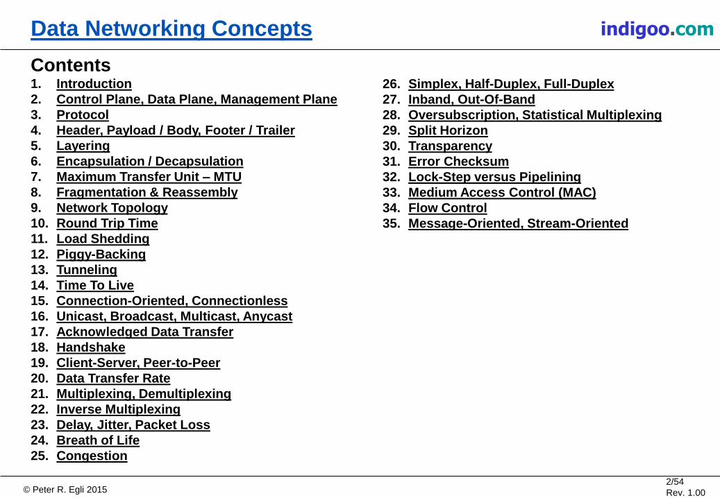
Contents 1. Introduction
2. Control Plane, Data Plane, Management Plane
3. Protocol
4. Header, Payload / Body, Footer / Trailer
5. Layering
6. Encapsulation / Decapsulation
7. Maximum Transfer Unit – MTU
8. Fragmentation & Reassembly
9. Network Topology
10. Round Trip Time
11. Load Shedding
12. Piggy-Backing
13. Tunneling
14. Time To Live
15. Connection-Oriented, Connectionless
16. Unicast, Broadcast, Multicast, Anycast
17. Acknowledged Data Transfer
18. Handshake
19. Client-Server, Peer-to-Peer
20. Data Transfer Rate
21. Multiplexing, Demultiplexing
22. Inverse Multiplexing
23. Delay, Jitter, Packet Loss
24. Breath of Life
25. Congestion
26. Simplex, Half-Duplex, Full-Duplex
27. Inband, Out-Of-Band
28. Oversubscription, Statistical Multiplexing
29. Split Horizon
30. Transparency
31. Error Checksum
32. Lock-Step versus Pipelining
33. Medium Access Control (MAC)
34. Flow Control
35. Message-Oriented, Stream-Oriented
© Peter R. Egli 2015 3/54
Rev. 1.00
indigoo.com Data Networking Concepts
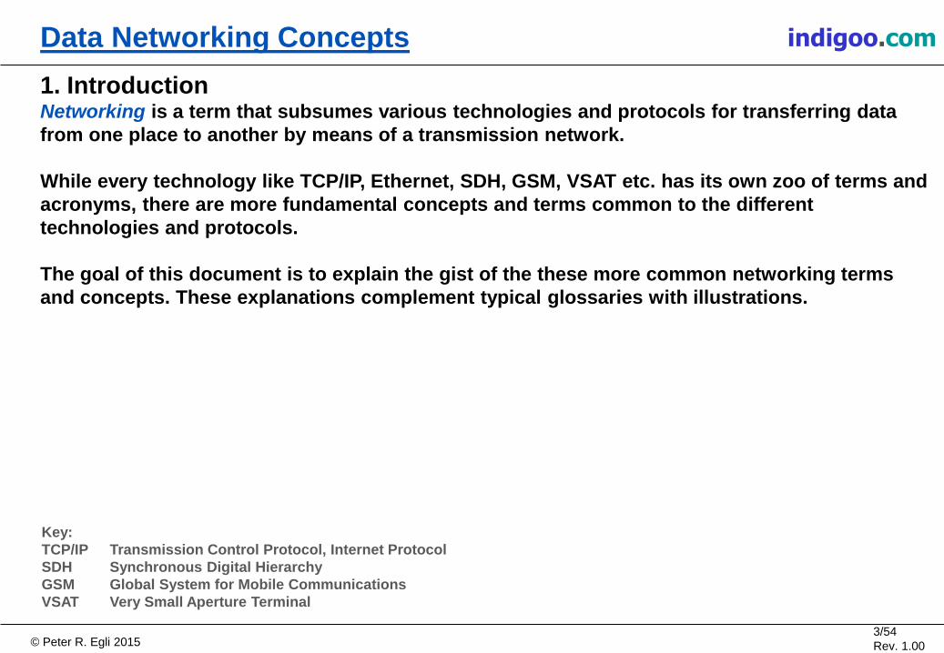
1. Introduction Networking is a term that subsumes various technologies and protocols for transferring data
from one place to another by means of a transmission network.
While every technology like TCP/IP, Ethernet, SDH, GSM, VSAT etc. has its own zoo of terms and
acronyms, there are more fundamental concepts and terms common to the different
technologies and protocols.
The goal of this document is to explain the gist of the these more common networking terms
and concepts. These explanations complement typical glossaries with illustrations.
Key:
TCP/IP Transmission Control Protocol, Internet Protocol
SDH Synchronous Digital Hierarchy
GSM Global System for Mobile Communications
VSAT Very Small Aperture Terminal
© Peter R. Egli 2015 4/54
Rev. 1.00
indigoo.com Data Networking Concepts
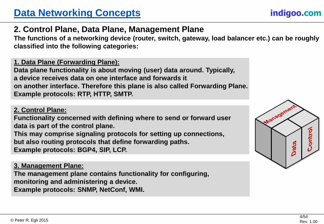
2. Control Plane, Data Plane, Management Plane The functions of a networking device (router, switch, gateway, load balancer etc.) can be roughly
classified into the following categories:
1. Data Plane (Forwarding Plane):
Data plane functionality is about moving (user) data around. Typically,
a device receives data on one interface and forwards it
on another interface. Therefore this plane is also called Forwarding Plane.
Example protocols: RTP, HTTP, SMTP.
2. Control Plane:
Functionality concerned with defining where to send or forward user
data is part of the control plane.
This may comprise signaling protocols for setting up connections,
but also routing protocols that define forwarding paths.
Example protocols: BGP4, SIP, LCP.
3. Management Plane:
The management plane contains functionality for configuring,
monitoring and administering a device.
Example protocols: SNMP, NetConf, WMI.

© Peter R. Egli 2015 5/54
Rev. 1.00
indigoo.com Data Networking Concepts
3. Protocol (1/4) Protocols define packet formats, encodings and message exchange patterns so that 2 devices
that both talk the same protocol are compatible (can talk to each other).
Protocols are organized in protocol stacks, each layer interacting with upper and lower layer
protocols.
Protocol Y
Upper layer
protocol (Z)
Lower layer
protocol (X)
Protocol Y
Upper layer
protocol (Z)
Lower layer
protocol (X)
Logically, protocol peers
talk to each other
(exchange PDUs).
Physically, PDUs are
passed to the peer via
lower layer protocol
layers. For the lower layer
(service provider), the
PDU is an SDU.
PDU Y
PDU Y
PDU X
PDU X
PDU Z PDU Z PDU Z PDU Z
PDU Z
PDU Z
PDU Y PDU Y PDU Y PDU Y
Key:
PDU Protocol Data Unit
SDU Service Data Unit

© Peter R. Egli 2015 6/54
Rev. 1.00
indigoo.com Data Networking Concepts
3. Protocol (2/4) Protocol service:
Protocols in a layer provide a service to the upper layer protocol.
The upper layer protocol is the consumer of the provided service.
The point where the service is provided is called
Service Access Point (SAP).
Upper and lower layer protocol exchange PDUs. For the lower layer
protocol, PDUs exchanged with the upper layer protocol represent
units of data of the service and are thus called Service Data Unit (SDU).
Protocol packets:
Protocol PDUs usually have a header and optionally
a footer (aka trailer), both consisting of protocol specific information.
The header is transmitted first, followed by the payload
and finally the trailer.
The payload carries upper layer information.
Payload as well as header and trailer consist
of information fields.
PDUs are called differently depending on layer and
protocol (packet, frame, cell, segment, datagram, APDU).
Lower layer
protocol
Upper layer
protocol
Payload Header Footer PDU
Field
PDU/SDU PDU/SDU
Key:
APDU Application Protocol Data Unit
SAP Service Access Point
SAP

© Peter R. Egli 2015 7/54
Rev. 1.00
indigoo.com Data Networking Concepts
3. Protocol (3/4) Packet exchange patterns:
Protocols define the events and situations that trigger the transmission of PDUs.
The most common packet exchange pattern in the application layer pattern is request-
response.
Lower layer protocols (OSI layer 2 and 3) are typically driven by the transmission of PDUs
from the upper layer, i.e. send a PDU on request of the upper layer protocol. In doing so, they
use the service of the lower layer protocol.
PDU
Protocol Y
Upper layer
protocol (Z)
Lower layer
protocol (X)
Protocol Y
Upper layer
protocol (Z)
Lower layer
protocol (X)
PDU
Key:
OSI Open Systems Interconnection

© Peter R. Egli 2015 8/54
Rev. 1.00
indigoo.com Data Networking Concepts
3. Protocol (4/4) Protocol meta-model:
Protocol entities and
relations based on
UML 2 (Unified Modeling
Language) notation.
Service
User
Service
Provider
Layer
Protocol
implements 1
SAP
1 Interface
Protocol
Stack
1..* 1 has
peers
with
1
PDU
Header
Frame
(L2)
Packet
(L3)
Segment
(TCP, L4)
APDU
(L5-7)
Footer 1 0..1
1
SDU
Payload
1
1
1 1 encapsulates
1
1..*
1
defines & exchanges with peer
has
is accessible on
1
1
1
Datagram
(UDP, L4)
provides
is
requires 1 1
Field 1 1..*
has
1
1..*
1..* 1 1
has
has
Cell
(L2)

© Peter R. Egli 2015 9/54
Rev. 1.00
indigoo.com Data Networking Concepts
4. Header, Payload / Body, Footer / Trailer Header:
Headers are prepended to the payload and contain information fields that are used for the
transmission of the packet to the destination (addresses, quality of service fields, time to live
etc.). Packets are transmitted with the header first.
Payload / body:
The payload contains the user data to be transmitted. Due to layering of protocols, the payload
may contain a header and optionally a footer of the upper layer protocol (layer n+1).
Footer / trailer:
Footers typically contain check codes for detecting and possibly correcting bit errors in the
packet. Footers are rarely used because packets are usually received in their entirety before
being processed so all relevant information can be placed into the header.
Header Payload
(body)
Footer
(trailer)
Layer n PDU
Layer n+1 PDU
= Layer n SDU
Transmission
direction
© Peter R. Egli 2015 10/54
Rev. 1.00
indigoo.com Data Networking Concepts
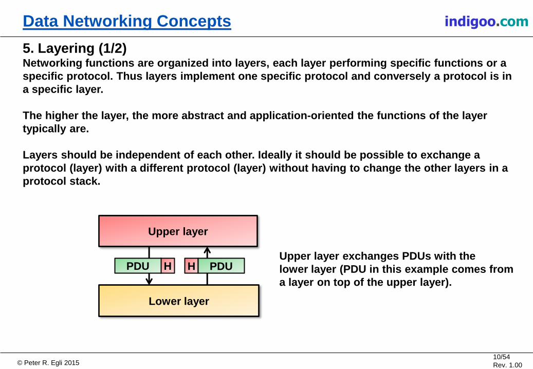
5. Layering (1/2) Networking functions are organized into layers, each layer performing specific functions or a
specific protocol. Thus layers implement one specific protocol and conversely a protocol is in
a specific layer.
The higher the layer, the more abstract and application-oriented the functions of the layer
typically are.
Layers should be independent of each other. Ideally it should be possible to exchange a
protocol (layer) with a different protocol (layer) without having to change the other layers in a
protocol stack.
Upper layer
Lower layer
H PDU H PDU Upper layer exchanges PDUs with the
lower layer (PDU in this example comes from
a layer on top of the upper layer).

© Peter R. Egli 2015 11/54
Rev. 1.00
indigoo.com Data Networking Concepts
Protocol Y
Upper layer protocol (Z)
Lower layer protocol (X)
PDU Z PDU Z
H PDU Z H PDU Z
H PDU Z H H PDU Z H
5. Layering (2/2) Protocol layers exchange information with the corresponding peer layer.
Layers logically "talk" to their peer layer (shown as horizontal packet flow) while physically
exchanging data with lower and upper layers.
Protocol Y
Upper layer protocol (Z)
Lower layer protocol (X)
PDU Z PDU Z
PDU Z
PDU Z
H PDU Z PDU Y
H PDU Z
H PDU Z H
H PDU Z H
PDU Y
PDU X
PDU X
H PDU Z H PDU Z
H PDU Z H H PDU Z H

© Peter R. Egli 2015 12/54
Rev. 1.00
indigoo.com Data Networking Concepts
6. Encapsulation / Decapsulation Encapsulation (E) designates the process of adding a packet as payload into another packet.
The receiver performs the reverse process called decapsulation (D).
Every protocol layer in a protocol stack receives a packet (PDU) from the upper layer and
performs encapsulation by adding a protocol header plus optionally a trailer (depending on the
protocol) to the packet.
Afterwards, the protocol layer passes the new packet on to the next lower layer where the
process repeats.
Upper layer (P2)
Upper layer (P1)
Lower layer (P3)
Protocol P2 adds its
header and a trailer
and passes the new
packet as a PDU to
the next lower layer.
Upper layer (P2)
Upper layer (P1)
Lower layer (P3)
E D
E D
E D
P1 P1
H P1 T H P1 T
H P1 T T H

© Peter R. Egli 2015 13/54
Rev. 1.00
indigoo.com Data Networking Concepts
7. Maximum Transfer Unit - MTU (1/2) MTU is the maximum size of protocol packets on a transmission line.
MTU (in bytes) affects different characteristics such as:
• Packet loss rate (PLR)
• Overhead (OH)
• Packet transmission delay (PTD)
• Required packet processing power on a protocol processing device (RPP)
MTU affects PLR, OH, PTD and RPP as follows:
𝑳𝒆𝒕 𝑩𝑬𝑹 = 𝑩𝒊𝒕 𝑬𝒓𝒓𝒐𝒓 𝑹𝒂𝒕𝒆, 𝒆. 𝒈. 𝟏𝟎−𝟏𝟐𝒔−𝟏 𝑳𝒆𝒕 𝑴𝑻𝑼 = 𝑴𝒂𝒙𝒊𝒎𝒖𝒎 𝑻𝒓𝒂𝒏𝒔𝒇𝒆𝒓 𝑼𝒏𝒊𝒕 𝑩𝒚𝒕𝒆 , 𝒆. 𝒈. 𝟏𝟓𝟎𝟎 𝑩𝒚𝒕𝒆 𝑳𝒆𝒕 𝑯𝑺 = 𝑯𝒆𝒂𝒅𝒆𝒓 𝑺𝒊𝒛𝒆, 𝒆. 𝒈. 𝟐𝟎 𝑩𝒚𝒕𝒆 𝑳𝒆𝒕 𝑳𝑩𝑹 = 𝑳𝒊𝒏𝒌 𝑩𝒊𝒕 𝑹𝒂𝒕𝒆, 𝒆. 𝒈. 𝟏𝟎𝟗 𝑩𝒊𝒕/𝒔 𝑳𝒆𝒕 𝑷𝑭 = 𝑹𝒆𝒒𝒖𝒊𝒓𝒆𝒅 𝑷𝒓𝒐𝒄𝒆𝒔𝒔𝒊𝒏𝒈 𝑷𝒐𝒘𝒆𝒓 𝒑𝒆𝒓 𝒑𝒂𝒄𝒌𝒆𝒕 (𝒆. 𝒈. 𝒏𝒖𝒎𝒃𝒆𝒓 𝒐𝒇 𝑪𝑷𝑼 𝒄𝒚𝒄𝒍𝒆𝒔)
𝑷𝑳𝑹 = 𝑴𝑻𝑼 ∗ 𝟖 ∗ 𝑩𝑬𝑹
𝑶𝑯 =𝑯𝑺
𝑴𝑻𝑼 𝑹𝑷𝑷 =
𝑷𝑭 ∗ 𝑳𝑩𝑹
𝑴𝑻𝑼 ∗ 𝟖
𝑷𝑻𝑫 =𝑴𝑻𝑼 ∗ 𝟖
𝑳𝑩𝑹

© Peter R. Egli 2015 14/54
Rev. 1.00
indigoo.com Data Networking Concepts
7. Maximum Transfer Unit - MTU (2/2) MTU optimization:
Larger MTUs positively affect overhead (becomes smaller) but negatively affect the
packet loss rate (higher probability of packet loss with larger MTUs).
Thus the MTU needs to be optimized regarding PLR, OH, PTD, RPP and other factors.
MTU can be optimized with respect to efficiency for PLR and OH as follows:
𝑴𝑻𝑼𝑬 = 𝑴𝑻𝑼 𝑬𝒇𝒇𝒊𝒄𝒊𝒆𝒏𝒄𝒚 = 𝑾𝑭𝟏 ∗ 𝑷𝑳𝑹 + 𝑾𝑭𝟐 ∗ 𝑶𝑯
𝑳𝒆𝒕 𝑾𝑭𝟏, 𝑾𝑭𝟐 = 𝑾𝒆𝒊𝒈𝒉𝒊𝒏𝒈 𝑭𝒂𝒄𝒕𝒐𝒓𝒔 𝒕𝒐 𝒈𝒊𝒗𝒆 𝑷𝑳𝑹 𝒂𝒏𝒅 𝑶𝑯 𝒅𝒊𝒇𝒇𝒆𝒓𝒆𝒏𝒕 𝒘𝒆𝒊𝒈𝒉𝒕𝒔 𝑴𝑻𝑼𝑬 = 𝑴𝑻𝑼 𝑬𝒇𝒇𝒊𝒄𝒊𝒆𝒏𝒄𝒚, 𝒇𝒂𝒄𝒕𝒐𝒓 𝒕𝒉𝒂𝒕 𝒆𝒙𝒑𝒓𝒆𝒔𝒔𝒆𝒔 𝒉𝒐𝒘 𝒆𝒇𝒇𝒊𝒄𝒊𝒆𝒏𝒕 𝒕𝒉𝒆 𝒕𝒓𝒂𝒏𝒔𝒎𝒊𝒔𝒔𝒊𝒐𝒏 𝒊𝒔 𝒂𝒔 𝒂 𝒇𝒖𝒏𝒄𝒕𝒊𝒐𝒏 𝒐𝒇 𝑴𝑻𝑼
Area of optimal
MTU, MTUE
is maximized.

© Peter R. Egli 2015 15/54
Rev. 1.00
indigoo.com Data Networking Concepts
8. Fragmentation & Reassembly Fragmentation (F) and reassembly (R) are processes in a protocol layer to break up a packet
into smaller chunks so they are not larger than the MTU (Maximum Transfer Unit).
If the lower layer does not support fragmentation (e.g. Ethernet), packets have to be fragmented
on the higher layer (e.g. IP in case of Ethernet).
Upper layer (P2)
Lower layer (P3)
Upper layer (P2)
Lower layer (P3)
H H
Upper layer (P1)
P1 H P1
MTU of
P3
MTU of
P3
F R
Upper layer (P1)
H P1
P1
H P1
P1

© Peter R. Egli 2015 16/54
Rev. 1.00
indigoo.com Data Networking Concepts
9. Network Topology (1/3) Basic network elements:
Networks consist of nodes (devices) and
wired or wireless links between the nodes.
Links are defined on OSI layer 1 (physical layer)
and OSI layer 2 (data link layer).
Network link types:
Physical links between nodes have either point-to-point or
multi-point (bus) characteristics.
Point-to-point links (P2P): Only 1 sender and 1 receiver.
No addressing needed.
MultiPoint links (MP): Multiple senders and receivers,
addressing and media access
control mechanism needed
(shared medium).
Link
P2P
Link
MP
Link
• Ethernet
• WLAN • RS232
• PPP
Typical
examples
Node
Node
Node Node
Link
Link
Link

© Peter R. Egli 2015 17/54
Rev. 1.00
indigoo.com Data Networking Concepts
9. Network Topology (2/3) Network topologies:
Based on the link types P2P and MP, different network topologies are possible.
Node
Hub
Node
Node
Node
Node
Node
Node
Star / hub & spoke:
The hub node has multiple
links to adjacent nodes
(spokes). Star topologies
are a special form of the
tree topology.
Node Node Node
Daisy-chain:
The nodes are connected
into a line. Each node except
the nodes at the end of the
line forward data for other
nodes.
Node Node Node
Bus:
The nodes are hooked up to
the same wire which acts as
a broadcast medium.
© Peter R. Egli 2015 18/54
Rev. 1.00
indigoo.com Data Networking Concepts
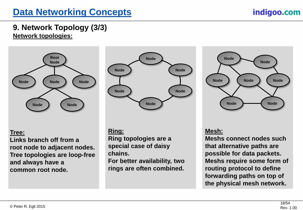
9. Network Topology (3/3) Network topologies:
Mesh:
Meshs connect nodes such
that alternative paths are
possible for data packets.
Meshs require some form of
routing protocol to define
forwarding paths on top of
the physical mesh network.
Ring:
Ring topologies are a
special case of daisy
chains.
For better availability, two
rings are often combined.
Node
Node Node
Node
Node
Node
Node
Node
Node
Node
Node
Node
Node Root
Node
Node Node
Node
Node
Node
Tree:
Links branch off from a
root node to adjacent nodes.
Tree topologies are loop-free
and always have a
common root node.

© Peter R. Egli 2015 19/54
Rev. 1.00
indigoo.com Data Networking Concepts
10. Round Trip Time (RTT) Round trip time is the time it takes for a packet, typically a request, to travel to the destination
and the response back to the original sender.
Processing time in the end systems is not part of the round trip time. However, the processing
time in the end system is usually negligible in comparison to the transmission time, so RTT is
simply measured as the time between request send time and response receive time.
Knowledge of RTT is important in many protocols. For example in TCP and SCTP, RTT is used to
dynamically adjust the retransmission timer (RTO).
Request
Host A Host B
Response
RTT -
Round
Trip
Time
Transmission time
AB
Transmission time
BA
Time
Processing
time

© Peter R. Egli 2015 20/54
Rev. 1.00
indigoo.com Data Networking Concepts
11. Load Shedding (1/2) A network device (switch, router, bridge etc.) receives packets and typically places these into an
interface input queue.
If ingress traffic rate (packets / s) exceeds the packet processing rate of the device for an
extended period of time, the queue fills up (congestion).
Once the interface input queue is full and still more packets arrive, the device has to discard
packets (= load shedding).
Interface input
queue (buffer)
Temporary burst
of packets
Packet
Processing
Output queue
Network device

© Peter R. Egli 2015 21/54
Rev. 1.00
indigoo.com Data Networking Concepts
11. Load Shedding (2/2) There exist different policies as to which packets to discard.
Wine policy:
Discard new packets first, keep the
old packets. Causes TCP connections
of new packets to throttle the rate,
thus allieviating the congestion.
Milk policy:
Drop old packets first, keep newly
arriving packets.
Better suited for multimedia traffic
where older packets carry
stale data (e.g. packetized voice).
Random early discard:
When queue fill status exceeds
a threshold, packets are randomly
selected and discarded.
Good overall performance, also
causes TCP connections to throttle.
Discard
Discard
Discard

© Peter R. Egli 2015 22/54
Rev. 1.00
indigoo.com Data Networking Concepts
12. Piggy-Backing In piggy-backing, unrelated processes use the same virtual communication channel to
exchange information as exemplified with P1 and P2 below.
A process P1 creates a packet with header, payload and trailer.
Before it is sent to the receiver, an unrelated process P2 places its information into the packet.
At the receiver side, the process is reversed. Both processes P1 and P2 pick up their related
information from the received packet.
Piggy-backing helps reducing the packet rate when small amounts of information (from P2)
would not warrant a separate packet thus reducing network load and increasing performance.
Sender
P1
P2
Receiver
P1
P2 Piggy-back
information

© Peter R. Egli 2015 23/54
Rev. 1.00
indigoo.com Data Networking Concepts
Protocol P2
13. Tunneling Tunneling makes use of the encapsulation technique.
With tunneling, a packet of protocol P1 may be transported transparently through a network
without using protocol P1 information.
A tunnel endpoint of tunneling protocol P2 receives a packet from the upper layer or another
protocol layer (P1) and encapsulates it (E) into a tunneling protocol packet (P2).
The receiving tunnel endpoint performs decapsulation (D).
The packet is forwarded based on protocol P2 header information while the protocol P1
packet remains untouched and is not used at all for any network forwarding function.
Tunneling is often used for VPNs (Virtual Private Networks) where different sites or hosts are
connected through tunnels.
H P1 E P1
Protocol P2
D H P1 P1
Tunnel endpoints

© Peter R. Egli 2015 24/54
Rev. 1.00
indigoo.com Data Networking Concepts
14. Time To Live Packets with unknown or broadcast destination address are often flooded to all network
interfaces by a networking device (switch, router etc.).
In case of a loop in the network topology, such packets will loop forever. Worse still, copies of
these packets will be generated thus swamping the network with traffic.
To avoid this situation, many protocols support a Time To Live (TTL) field in the header that is
initialized to a value by the sending device and decremented by each hop in the transmission
path.
Once the TTL field reaches zero, the packet is dropped.
Payload TTL=4 Payload TTL=3
Payload TTL=2
Payload TTL=1 Payload TTL=0
Drop!
Loop
Topology
Payload TTL=0
Drop!
Payload TTL=3
Payload TTL=2
Payload TTL=1

© Peter R. Egli 2015 25/54
Rev. 1.00
indigoo.com Data Networking Concepts
15. Connection-Oriented, Connectionless (1/2) The communication style of protocols can be classified as connection-oriented or connection-
less.
A. Connection-oriented:
In connection-oriented communication, 2 communication partners (peers A and B) first establish
a logical point-to-point relationship (=connection) with each other. After establishing the
connection, all traffic injected into either endpoint is delivered to the other endpoint and peer.
The network inbetween is often unaware of connections. The routers, switches etc. in the
network forward traffic on a packet-by-packet basis without considering connections.
Peer
A
Peer
B
Logical connection
Connection
endpoint
Connection
endpoint
Packet Packet Packet

© Peter R. Egli 2015 26/54
Rev. 1.00
indigoo.com Data Networking Concepts
15. Connection-Oriented, Connectionless (2/2) B. Connection-less:
A connection-less protocol allows a peer A to send messages to different peers (B…D)
without first establishing a logical connection.
Analogy with old-style communication:
Connection-oriented communication can be
compared with good old telephony service.
Connection-less communication resembles
postal correspondence.
Peer
A
Peer
B
Peer
C
Peer
D
© Peter R. Egli 2015 27/54
Rev. 1.00
indigoo.com Data Networking Concepts
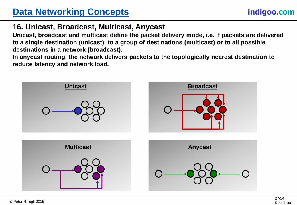
16. Unicast, Broadcast, Multicast, Anycast Unicast, broadcast and multicast define the packet delivery mode, i.e. if packets are delivered
to a single destination (unicast), to a group of destinations (multicast) or to all possible
destinations in a network (broadcast).
In anycast routing, the network delivers packets to the topologically nearest destination to
reduce latency and network load.
Unicast Broadcast
Multicast Anycast
© Peter R. Egli 2015 28/54
Rev. 1.00
indigoo.com Data Networking Concepts
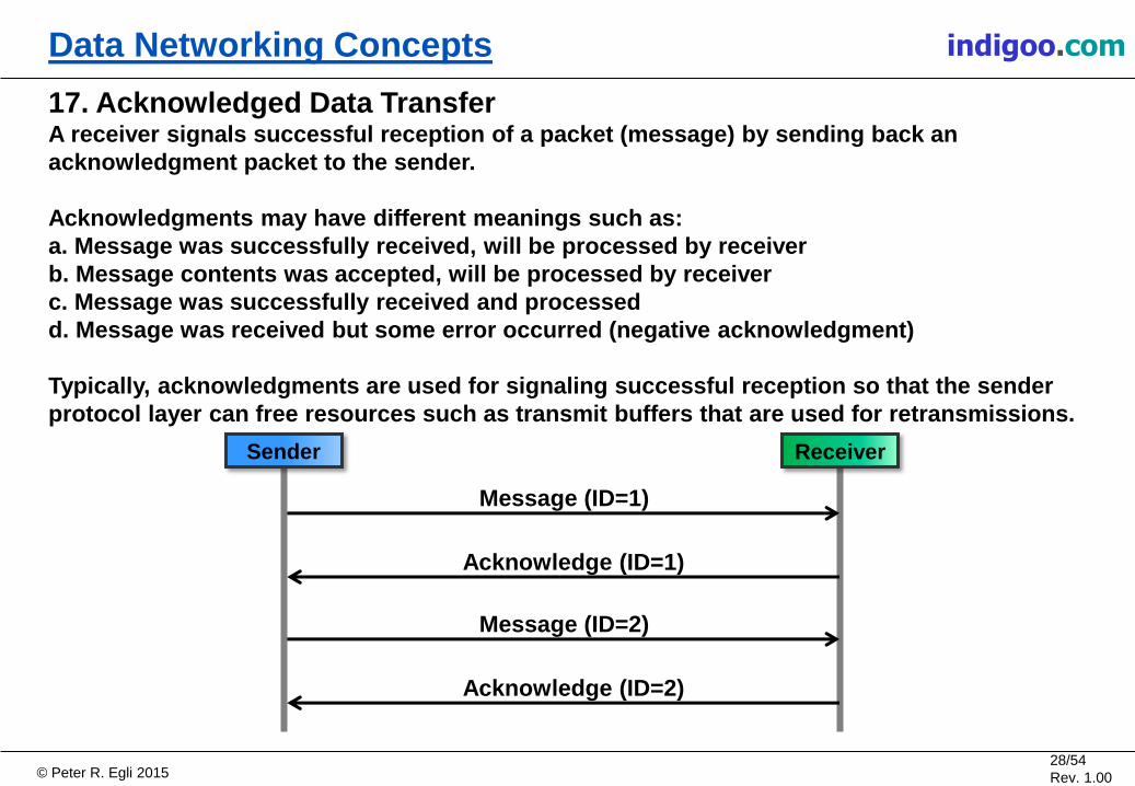
17. Acknowledged Data Transfer A receiver signals successful reception of a packet (message) by sending back an
acknowledgment packet to the sender.
Acknowledgments may have different meanings such as:
a. Message was successfully received, will be processed by receiver
b. Message contents was accepted, will be processed by receiver
c. Message was successfully received and processed
d. Message was received but some error occurred (negative acknowledgment)
Typically, acknowledgments are used for signaling successful reception so that the sender
protocol layer can free resources such as transmit buffers that are used for retransmissions.
Message (ID=1)
Sender Receiver
Acknowledge (ID=1)
Message (ID=2)
Acknowledge (ID=2)

© Peter R. Egli 2015 29/54
Rev. 1.00
indigoo.com Data Networking Concepts
18. Handshake Handshake is a procedure employed by two peers to synchronize and exchange information
needed in the subsequent communication.
A handshake is typically a threeway packet exchange initiated by one peer.
Peer B accepts the information sent by peer A (Peer-A-ID in the example below) and sends back
an acknowledgment along with its own ID (Peer-B-ID).
Finally, peer A acknowledges peer B's ID by returning an acknowlegment.
Peer-A-ID = 1
Peer A Peer B
Ack Peer-A-ID, Peer-B-ID = 2
Ack Peer-B-ID
© Peter R. Egli 2015 30/54
Rev. 1.00
indigoo.com Data Networking Concepts
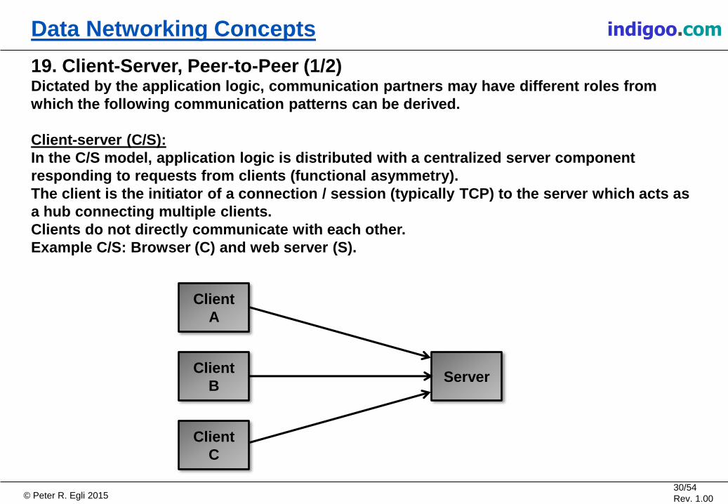
19. Client-Server, Peer-to-Peer (1/2) Dictated by the application logic, communication partners may have different roles from
which the following communication patterns can be derived.
Client-server (C/S):
In the C/S model, application logic is distributed with a centralized server component
responding to requests from clients (functional asymmetry).
The client is the initiator of a connection / session (typically TCP) to the server which acts as
a hub connecting multiple clients.
Clients do not directly communicate with each other.
Example C/S: Browser (C) and web server (S).
Client
B Server
Client
A
Client
C

© Peter R. Egli 2015 31/54
Rev. 1.00
indigoo.com Data Networking Concepts
19. Client-Server, Peer-to-Peer (2/2) Peer-to-peer (P2P):
In the P2P model, all peers have the same functionality and communicate directly with each
other.
Each peer can initiate a connection / session to any other peer. There is no central component
therefore this model is resilient against failures of individual peers.
Network and computing load is distributed more evenly compared to the centralized C/S model.
Example: File sharing platform.
Peer
B
Peer
D
Peer
A
Peer
C
© Peter R. Egli 2015 32/54
Rev. 1.00
indigoo.com Data Networking Concepts
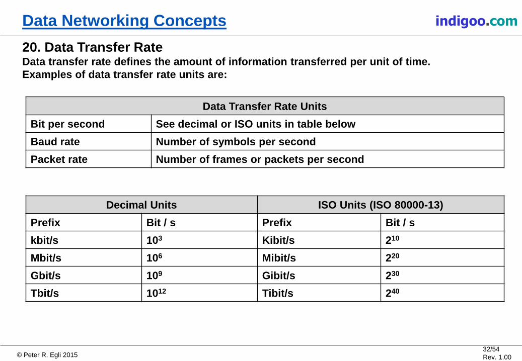
20. Data Transfer Rate Data transfer rate defines the amount of information transferred per unit of time.
Examples of data transfer rate units are:
Decimal Units ISO Units (ISO 80000-13)
Prefix Bit / s Prefix Bit / s
kbit/s 103 Kibit/s 210
Mbit/s 106 Mibit/s 220
Gbit/s 109 Gibit/s 230
Tbit/s 1012 Tibit/s 240
Data Transfer Rate Units
Bit per second See decimal or ISO units in table below
Baud rate Number of symbols per second
Packet rate Number of frames or packets per second

© Peter R. Egli 2015 33/54
Rev. 1.00
indigoo.com Data Networking Concepts
21. Multiplexing, Demultiplexing In multiplexing, data from multiple input lines (physical or logical connections) is aggregated
and sent out a single output line.
On the receiver side, a demultiplexer performs the reverse operation by breaking up the data
stream into the original input data streams.
Mux / Demux pairs are typically used to save transmission lines or resources for logical
connections on end systems.
MU
X
DE
MU
X
Packet
Packet Packet
Packet
Packet Packet
Packet
Packet
Packet Packet
Packet Packet

© Peter R. Egli 2015 34/54
Rev. 1.00
indigoo.com Data Networking Concepts
22. Inverse Multiplexing Inverse multiplexing is used to distribute traffic over multiple lines, e.g. for load distribution
over a number of physical lines.
Since some protocols are sensitive to reordering of packets (e.g. VoIP), inverse multiplexing
must make sure that the receiver demultiplexes packets into the same order as they were
received by the sender. This is typically achieved by adding some additional header to the
packets carrying sequencing information.
An additional benefit of inverse multiplexing may be some form of redundancy. If one of the
physical transmission lines fails, communication is still possible over the remaining
transmission lines.
DE
MU
X
Packet Packet
Packet
Packet Packet
Packet Packet
Packet Packet
MU
X
DE
MU
X
© Peter R. Egli 2015 35/54
Rev. 1.00
indigoo.com Data Networking Concepts
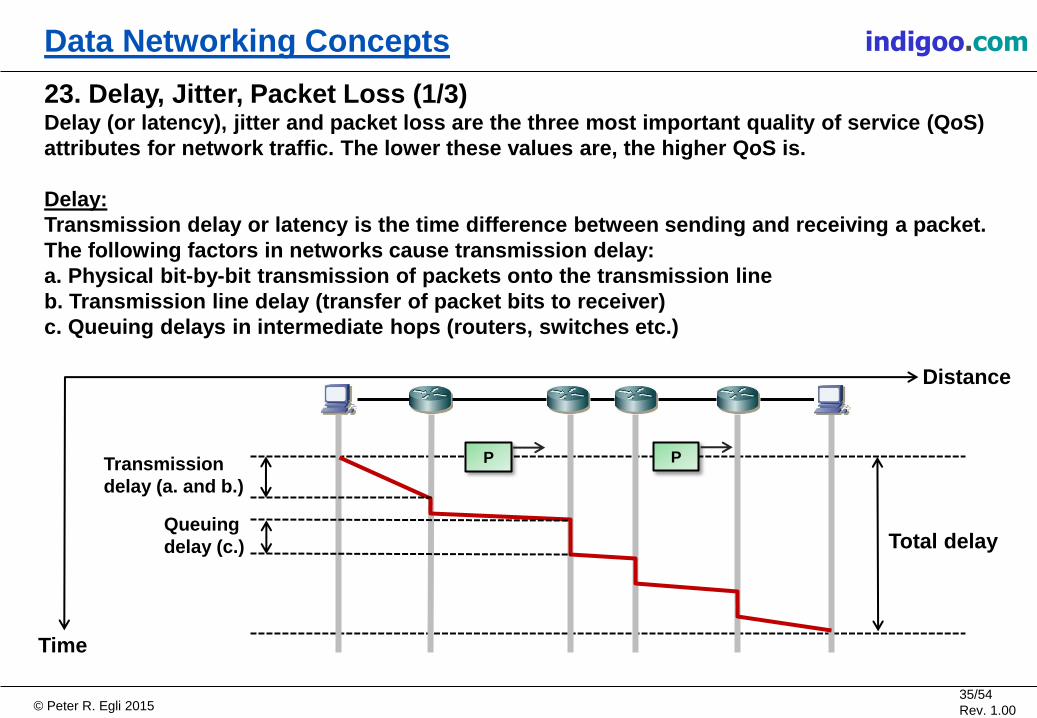
23. Delay, Jitter, Packet Loss (1/3) Delay (or latency), jitter and packet loss are the three most important quality of service (QoS)
attributes for network traffic. The lower these values are, the higher QoS is.
Delay:
Transmission delay or latency is the time difference between sending and receiving a packet.
The following factors in networks cause transmission delay:
a. Physical bit-by-bit transmission of packets onto the transmission line
b. Transmission line delay (transfer of packet bits to receiver)
c. Queuing delays in intermediate hops (routers, switches etc.)
Time
Distance
P
Total delay
Transmission
delay (a. and b.)
Queuing
delay (c.)
P

© Peter R. Egli 2015 36/54
Rev. 1.00
indigoo.com Data Networking Concepts
23. Delay, Jitter, Packet Loss (2/3) Jitter:
Delay varies from packet to packet. This variation is called jitter. Jitter is expressed as the
temporal deviation of packet arrival times from some reference point in time.
Bursts of packets (many packets in quick succession) are an indication of high jitter values.
P
Network
introduces delay
and jitter
Packets are sent at evenly
spaced intervals
P P P P P P P P P
Packet burst
Packets arrive at uneven intervals
(either earlier or later than some
reference point in time).
Time

© Peter R. Egli 2015 37/54
Rev. 1.00
indigoo.com Data Networking Concepts
23. Delay, Jitter, Packet Loss (3/3) Packet loss:
Network devices typically discard packets in case of problems, i.e. they do not try to retransmit
packets but leave the decision which packets to drop up to the application.
This way the network devices are offloaded from such functions. Additionally it does not make
sense for all protocols such as VoIP to retransmit lost packets.
Packet loss may occur due to the following reasons:
a. unrecoverable bit error, checksum error
b. queue overflow (see load shedding)
c. packet collisions on multi-access networks (e.g. bus)
Packet discards due
to queue overflow (b.)
Packet loss due to
collision (c.)
Packet discard
due to bit error
such as bit flip (a.)

© Peter R. Egli 2015 38/54
Rev. 1.00
indigoo.com Data Networking Concepts
24. Breath of Life Breath of life (BOFL) is a simple means of protocol layers to supervise a connection or session.
Each peer of a connection or session periodically sends BOFL messages (protocol fields in
protocol header) to the peer to:
a. signal that it is still up and running and reachable over the network and
b. acknowledge BOFL messages of the peer.
To reduce overhead, BOFL messages are typically piggy-backed onto data messages when data
is present.
BOFL (I'm still here,
acknowledge peer BOFL) Protocol
Peer A
Protocol
Peer B
Data
H Data
H
H
H
BOFL piggy-backed
onto data packet
Data message
arriving from the
upper layer,
e.g. over socket
interface

© Peter R. Egli 2015 39/54
Rev. 1.00
indigoo.com Data Networking Concepts
25. Congestion Congestion describes a situation when ingress traffic temporarily exceeds egress capacity.
Congestion typically occurs in packet switching (routing) networks.
Output buffers (queues) are able to accommodate some excess traffic. Once the output queue is
full, incoming packets must be discarded (see load shedding).
Network device
Packet
Processing P P P P P
P
P
Output queue
Packet drop
due to congestion

© Peter R. Egli 2015 40/54
Rev. 1.00
indigoo.com Data Networking Concepts
26. Simplex, Half-Duplex, Full-Duplex Simplex, half-duplex and full-duplex denote communication styles between communication
peers, typically on the physical and data link layer.
Simplex:
Simplex communication means that
communication is possible
only in one direction.
Example: Signal broadcasing
Half-duplex:
Half-duplex devices first check if there is
traffic and only send data if the transmission
medium is free ("listen before talk").
Examples: Walkie-talkie, half-duplex Ethernet
Full-duplex:
In full-duplex communication, both
communication partners can send and
receive data at the same time.
Example: Full-duplex Ethernet
or
Peer A Peer B Data
Data

© Peter R. Egli 2015 41/54
Rev. 1.00
indigoo.com Data Networking Concepts
27. Inband, Out-Of-Band (1/2) In-band (IB) and out-of-band (OOB) refer to the way signaling and management traffic is
exchanged with a networking device.
Physical out-of-band means that a separate physical line or frequency band is used for
signaling or management traffic. Logical out-of-band means that a separate channel or logical
connection is used.
Physical in-band:
The same physical line or frequency band is
used for exchanging signaling or management
information with a device.
Example: DTMF signaling in voice calls
(analog telephony)
Physical out-of-band:
A separate frequency band or a separate
communication line is used for signaling
or management.
Example: Separate modem line
for remote management over PSTN
(Public Switched Telephony Network)
300Hz 3.3kHz
f [Hz]
Voice channel band 8 in-band
frequencies
for DTMS
signaling
IP IP
PSTN
Modem
Modem

© Peter R. Egli 2015 42/54
Rev. 1.00
indigoo.com Data Networking Concepts
27. Inband, Out-Of-Band (2/2) Logical in-band:
Signaling or management traffic (S) is multiplexed into the user data stream (D) within a
logical connection or session.
Example: Tunnel control signaling in L2TP tunnel connection
Logical out-of-band:
User traffic (D) and signaling or
management packets (S) are
sent over a different
logical channel (e.g. different TCP
connection or UDP port number).
Example: VoIP with user traffic
in RTP channel, SIP signaling
over a separate UDP port number
L2TP tunnel D
S
D D S
D User data
process
Sig.
process
D D D
Data
process
Sig.
process
D D
S
D D D D User data
process
SIP Sig.
process
User data
process
SIP Sig.
process S
S

© Peter R. Egli 2015 43/54
Rev. 1.00
indigoo.com Data Networking Concepts
28. Oversubscription, Statistical Multiplexing (1/2) In networking systems, input lines (physical connections, logical channels) often need to be
aggregated (multiplexed) into an output line.
Since the capacity of the input lines is never fully utilized and traffic bursts on these input lines
are statistically distributed over time, the effective aggregated input traffic is only a fraction of
the theoretical maximum.
Input
Line 1
Input
Line 2
Input
Line 3
Effective aggregated input traffic is
only a fraction of the theoretical
maximum of input capacity
("peak of sums < sum of peaks")

© Peter R. Egli 2015 44/54
Rev. 1.00
indigoo.com Data Networking Concepts
28. Oversubscription, Statistical Multiplexing (2/2) For economic reasons, the output line typically only provides a fraction of the capacity of the
aggregated input capacity thus saving costs.
The output capacity needs to be carefully selected to minimize costs (hardware, bit rate) but still
accommodate traffic bursts on the input lines to a certain degree.
Multiplexer
D D D
D D
D D
D
D
D D D D
Aggregate capacity of input lines
exceeds output line capacity
Output
capacity
Example oversubscription rates
Ethernet switch access to distribution 20:1
Telephony PBX (Private Branch Exchange) phone lines to trunk lines 10:1
WLAN access point number of total clients versus active clients 5:1

© Peter R. Egli 2015 45/54
Rev. 1.00
indigoo.com Data Networking Concepts
29. Split Horizon Split horizon is a technique used in some networking protocols such as RIP (Routing
Information Protocol) to mitigate the effects of routing loops.
The split horizon mechanism is simple:
Never send received (routing) packets back to the sender of the packet.
Rationale: The sender already has the information in the packet thus it does not make sense to
return this information to the sender.
In the example below, R1 receives the routing packet P and forwards it to R4 but not back
to R2 from where R1 received the packet.
P
Horizon
P
P
R1 R2
R4 R3

© Peter R. Egli 2015 46/54
Rev. 1.00
indigoo.com Data Networking Concepts
30. Transparency Transparency means that some characteristic of a lower layer protocol is invisible to the upper
protocol layer(s).
Example: The lower layer protocol provides reliable data transfer including retransmissions in
case of errors. The lower layer performs this function transparently to the upper layer, i.e. the
upper layer is not involved in this function in any way.
Upper layer
protocol Y
Lower layer
protocol (X)
Upper layer
protocol Y
Lower layer
protocol (X)
PDU Y
PDU Y
PDU X
PDU X
PDU Y PDU Y PDU Y PDU Y
The internal operation of the lower layer including
retransmissions is invisible (transparent) to the upper layer
Only the interface to
the lower layer is
visible to the upper
layer

© Peter R. Egli 2015 47/54
Rev. 1.00
indigoo.com Data Networking Concepts
31. Error Checksum Checksums (CS) are often part of a protocol header to detect bit errors.
Usually checksums are only used to detect transmission errors.
With FEC (Forward Error Check) codes, however, it is even possible to correct bit errors up to a
maximum number of bit errors within a packet.
Header Payload
(body) CS
Calculate
checksum
Sender operation:
The sender calculates the checksum over
the payload (and possibly parts of the
header) and places the checksum into
the header.
Header Payload
(body) CS
Calculate
checksum
Pass / fail
Receiver operation:
The receiver too calculates the checksum and
compares the value with the checksum in the
header.
In case of equality, the payload is passed to
the upper layer, in case of a mismatch the packet
is dropped.
=?

© Peter R. Egli 2015 48/54
Rev. 1.00
indigoo.com Data Networking Concepts
32. Lock-Step versus Pipelining (1/2) Lock-step and pipelining are two modes of acknowledged data transfer between two nodes.
Lock-step:
In a lock-step protocol, a sender must receive an aknowledegment from the receiver before it
can send the next packet.
Host A Host B
Data
Acknowledge
Data
Acknowledge
Data
Acknowledge
𝑹𝒎𝒂𝒙 =MTU / RTT
𝑳𝒆𝒕 𝑴𝑻𝑼 = 𝑴𝒂𝒙𝒊𝒎𝒖𝒎 𝑻𝒓𝒂𝒏𝒔𝒇𝒆𝒓 𝑼𝒏𝒊𝒕 𝑩𝒚𝒕𝒆 , 𝒆. 𝒈. 𝟏𝟓𝟎𝟎 𝑩𝒚𝒕𝒆 𝑳𝒆𝒕 𝑹𝑻𝑻 = 𝑹𝒐𝒖𝒏𝒅 𝑻𝒓𝒊𝒑 𝑻𝒊𝒎𝒆, 𝒆. 𝒈. 𝟓𝟎𝒎𝒔
In a lock-step protocol, the maximum data rate 𝑹𝒎𝒂𝒙 is
limited by RTT and maximum packet size (𝑴𝑻𝑼).

© Peter R. Egli 2015 49/54
Rev. 1.00
indigoo.com Data Networking Concepts
32. Lock-Step versus Pipelining (2/2) Pipelining:
A protocol that makes use of pipelining allows a sender to send multiple packets without the
need to wait for an acknowledegment.
Typically, the maximum amount of data a sender can send without the need to wait for an
acknolwedgement is defined by the receive buffer size. In TCP, this size is called Window Size.
Host A Host B
Data
Data
Acknowledge
Data
Acknowledge
Data
Data
Data
𝑹𝒎𝒂𝒙 = 𝑾𝑺 / RTT
𝑳𝒆𝒕 𝑾𝑺 = 𝑾𝒊𝒏𝒅𝒐𝒘 𝑺𝒊𝒛𝒆 𝑩𝒚𝒕𝒆 , 𝒆. 𝒈. 𝟔𝟓𝟓𝟑𝟓 𝑩𝒚𝒕𝒆 𝑳𝒆𝒕 𝑹𝑻𝑻 = 𝑹𝒐𝒖𝒏𝒅 𝑻𝒓𝒊𝒑 𝑻𝒊𝒎𝒆, 𝒆. 𝒈. 𝟓𝟎𝒎𝒔
With pipelining, the maximum data rate 𝑹𝒎𝒂𝒙 is given
by the window size 𝑾𝑺 and RTT.
© Peter R. Egli 2015 50/54
Rev. 1.00
indigoo.com Data Networking Concepts
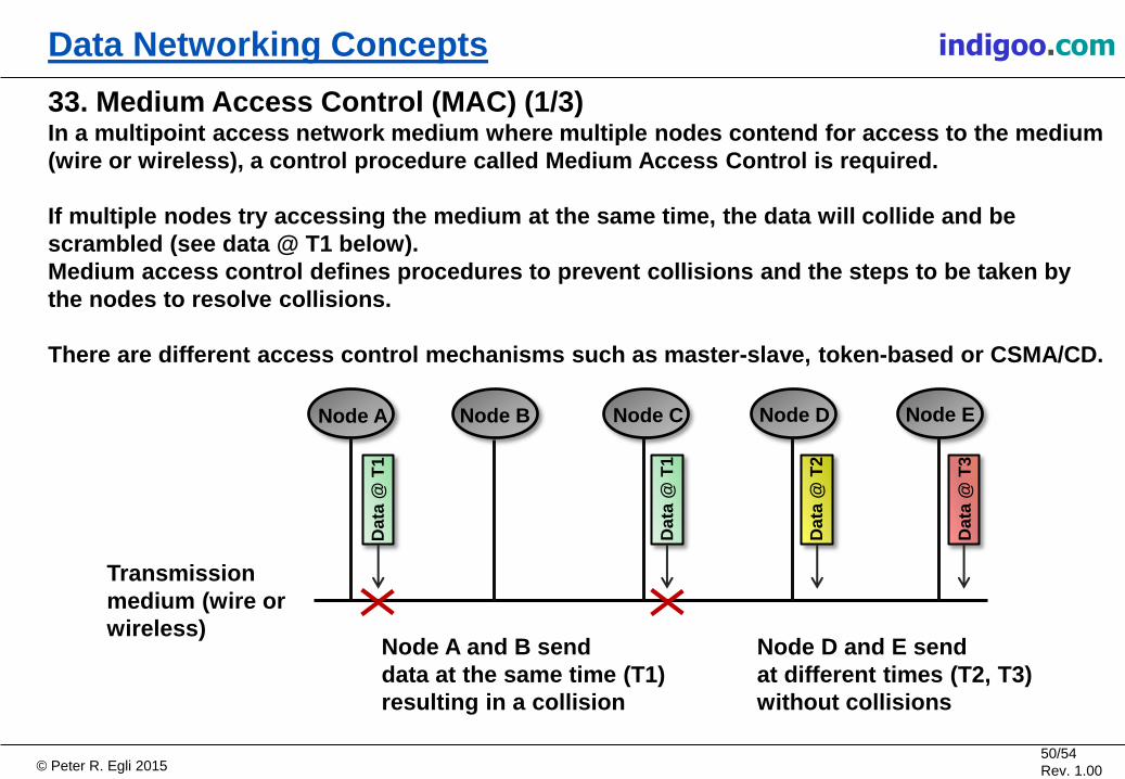
33. Medium Access Control (MAC) (1/3) In a multipoint access network medium where multiple nodes contend for access to the medium
(wire or wireless), a control procedure called Medium Access Control is required.
If multiple nodes try accessing the medium at the same time, the data will collide and be
scrambled (see data @ T1 below).
Medium access control defines procedures to prevent collisions and the steps to be taken by
the nodes to resolve collisions.
There are different access control mechanisms such as master-slave, token-based or CSMA/CD.
Transmission
medium (wire or
wireless)
Data
@ T
1
Data
@ T
1
Da
ta @
T2
Data
@ T
3
Node A and B send
data at the same time (T1)
resulting in a collision
Node A Node B Node C Node D Node E
Node D and E send
at different times (T2, T3)
without collisions
© Peter R. Egli 2015 51/54
Rev. 1.00
indigoo.com Data Networking Concepts
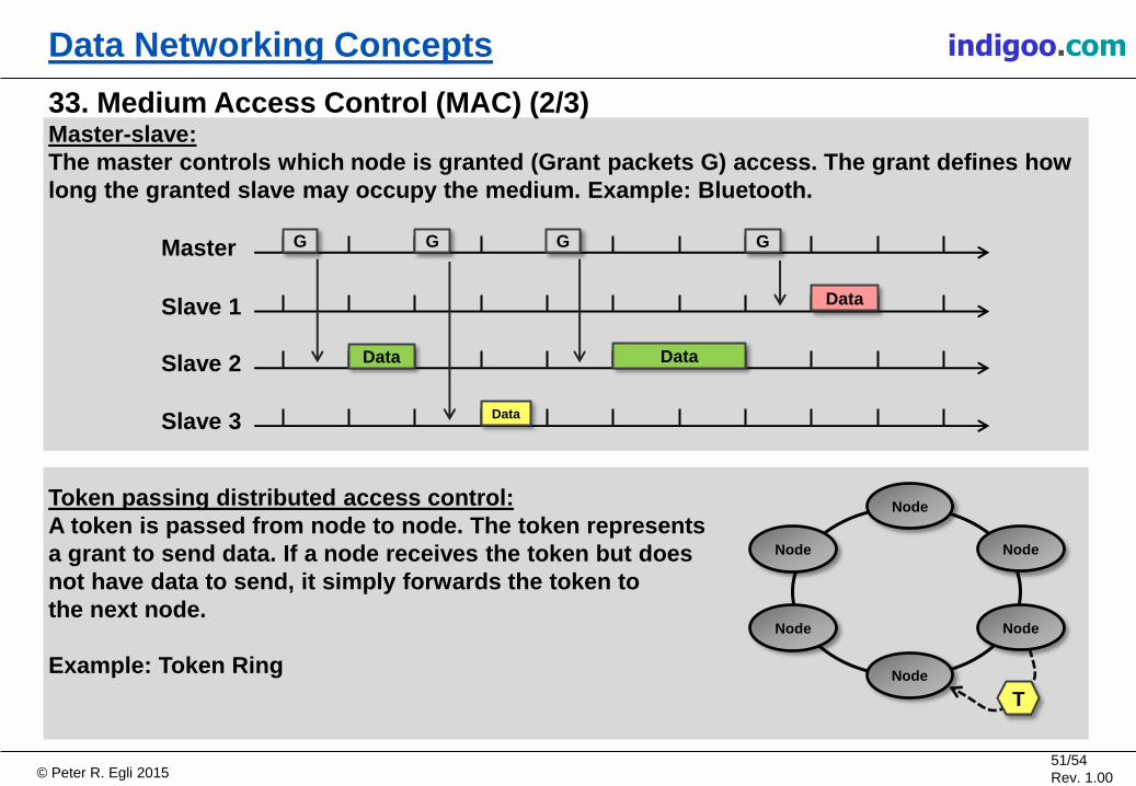
33. Medium Access Control (MAC) (2/3) Master-slave:
The master controls which node is granted (Grant packets G) access. The grant defines how
long the granted slave may occupy the medium. Example: Bluetooth.
Token passing distributed access control:
A token is passed from node to node. The token represents
a grant to send data. If a node receives the token but does
not have data to send, it simply forwards the token to
the next node.
Example: Token Ring
Slave 1
Slave 2
Slave 3
Master G G G G
Data
Data
Data
Data
Node
Node
Node
Node
Node
Node
T
© Peter R. Egli 2015 52/54
Rev. 1.00
indigoo.com Data Networking Concepts
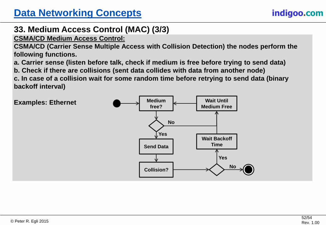
33. Medium Access Control (MAC) (3/3) CSMA/CD Medium Access Control:
CSMA/CD (Carrier Sense Multiple Access with Collision Detection) the nodes perform the
following functions.
a. Carrier sense (listen before talk, check if medium is free before trying to send data)
b. Check if there are collisions (sent data collides with data from another node)
c. In case of a collision wait for some random time before retrying to send data (binary
backoff interval)
Examples: Ethernet Medium
free?
Send Data
Wait Until
Medium Free
Collision?
Yes
No
Yes
No
Wait Backoff
Time

© Peter R. Egli 2015 53/54
Rev. 1.00
indigoo.com Data Networking Concepts
34. Flow Control Reliable transport protocols such as TCP or SCTP provide flow control to avoid packet loss
under normal conditions, i.e. non-congested networks.
Each transport layer contains a logical transmit and receive process. The transmit process
regularly obtains the size of free receive buffer space and piggy-backs this information onto
transmit packets. The transmit process of the peer transport layer receives this information
and ensures that it never sends more data than the peer's receive buffer can accommodate.
This ensures that no buffer overflows can occur on both sides.
P
Transport layers each
with transmit and receive
processes with buffers
2 simplex logical channels
P P
Upper layer
P P
P P P
P P
P
P P
Upper layer
P P
© Peter R. Egli 2015 54/54
Rev. 1.00
indigoo.com Data Networking Concepts
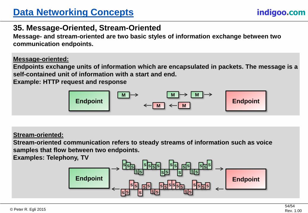
35. Message-Oriented, Stream-Oriented Message- and stream-oriented are two basic styles of information exchange between two
communication endpoints.
Message-oriented:
Endpoints exchange units of information which are encapsulated in packets. The message is a
self-contained unit of information with a start and end.
Example: HTTP request and response
Stream-oriented:
Stream-oriented communication refers to steady streams of information such as voice
samples that flow between two endpoints.
Examples: Telephony, TV
Endpoint Endpoint M
Endpoint
S
M M
M M
S S S S
S S S S
S S
S S
S
S S
S S
S S S
S S
S S
S
S S
S S
S S S S S S
S S
S S S S
Endpoint