C2SiS Networking Concepts
45
Networking Concepts
-
Upload
ankit-goel -
Category
Documents
-
view
227 -
download
0
description
networking
Transcript of C2SiS Networking Concepts
Networking Concepts
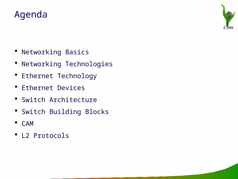
Agenda
Networking Basics
Networking Technologies
Ethernet Technology
Ethernet Devices
Switch Architecture
Switch Building Blocks
CAM
L2 Protocols
Node Anything connected to the network, usually a computer, but it could
be a printer or a scanner
Segment Any portion of a network that is separated by a switch, bridge or a
router from another part of a network
Backbone The main cabling of a network that all of the segment connect to.
Usually, the backbone is capable of carrying more information than the individual segments
Topology The way each node is physically connected to the network
Networking Basics – Key Network Terminologies
Wired Networks Wireless Networks Mobile Networks
Networking Basics – Types of connections
Wired Connections Physically connect computers together Use of wires or optical cables Connections are called network links
Physical Links Twisted pair Coaxial cable Fiber-optic cable
Multi Mode Fiber MM is optical fiber that is designed to carry multiple light rays or
modes concurrently, each at a slightly different reflection angle within the optical fiber core
used for relatively short distances because the modes tend to disperse over longer lengths
Single Mode Fiber For longer distances, single mode fiber (Sometimes called
Monomode) fiber is used In single mode fiber a single ray or mode of light act as a carrier
Networking Basics – Wired Connections
Networking Basics – Wireless Connections
Wireless connections Link is made using electromagnetic energy that goes through space Do not use any wires or cables
Wireless Communications commonly used in Networking Infrared Radio Frequency Microwave

Topology Bus, Star, Mesh, Ring, Tree
Category according to the size LAN
A collection of nodes within a small area Nodes linked through topology
MAN Consists of many local area networks linked together Span the distance of just a few miles
WAN Consists of a number of computer networks including LANs Links national/international boundaries
Networking Basics – Network Topology & Category
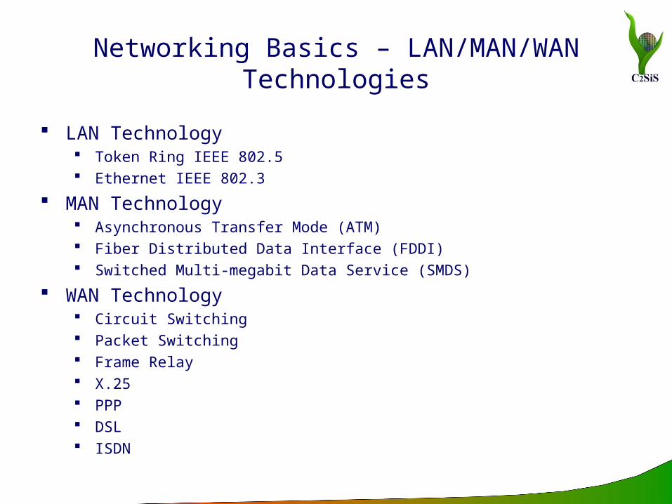
Networking Basics – LAN/MAN/WAN Technologies
LAN Technology Token Ring IEEE 802.5 Ethernet IEEE 802.3
MAN Technology Asynchronous Transfer Mode (ATM) Fiber Distributed Data Interface (FDDI) Switched Multi-megabit Data Service (SMDS)
WAN Technology Circuit Switching Packet Switching Frame Relay X.25 PPP DSL ISDN
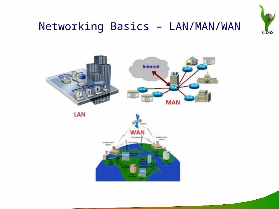
Networking Basics – LAN/MAN/WAN
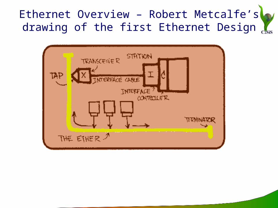
Ethernet Overview – Robert Metcalfe’s drawing of the first Ethernet Design
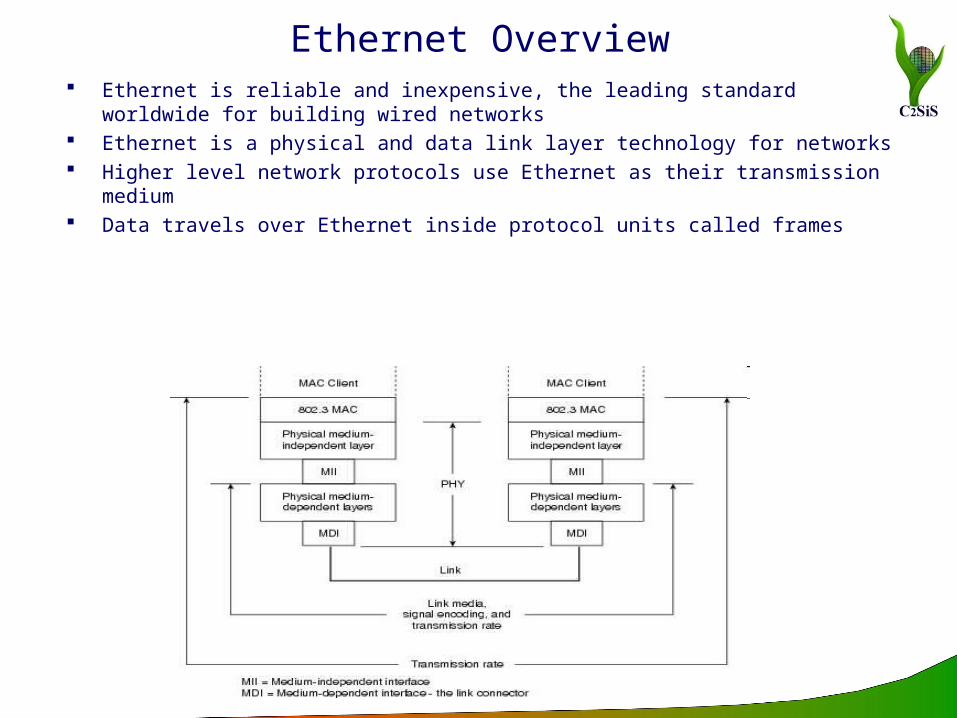
Ethernet Overview Ethernet is reliable and inexpensive, the leading standard worldwide
for building wired networks Ethernet is a physical and data link layer technology for networks Higher level network protocols use Ethernet as their transmission
medium Data travels over Ethernet inside protocol units called frames
Ethernet Overview
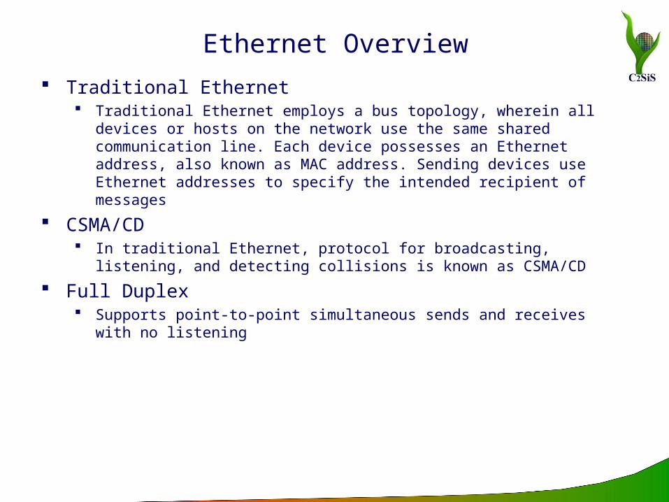
Traditional Ethernet Traditional Ethernet employs a bus topology, wherein all devices or
hosts on the network use the same shared communication line. Each device possesses an Ethernet address, also known as MAC address. Sending devices use Ethernet addresses to specify the intended recipient of messages
CSMA/CD In traditional Ethernet, protocol for broadcasting, listening, and
detecting collisions is known as CSMA/CD
Full Duplex Supports point-to-point simultaneous sends and receives with no
listening
Ethernet Evolution
10BaseX (10BaseT)
Fast Ethernet
Gigabit Ethernet
10Gigabit Ethernet
40/100 Gigabit Ethernet
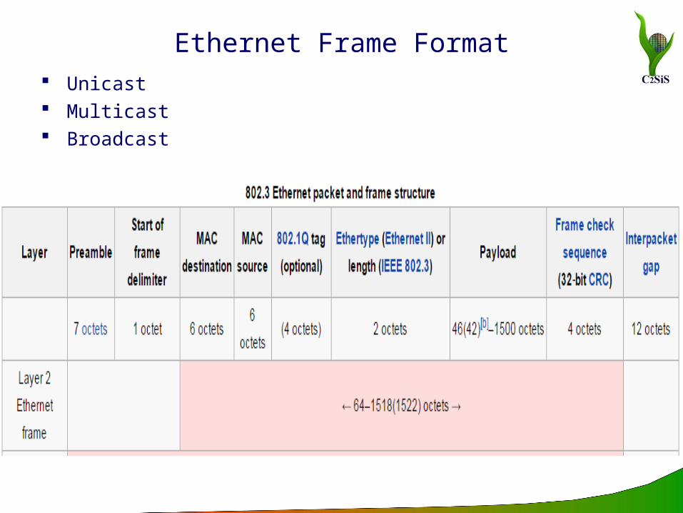
Ethernet Frame Format Unicast Multicast Broadcast
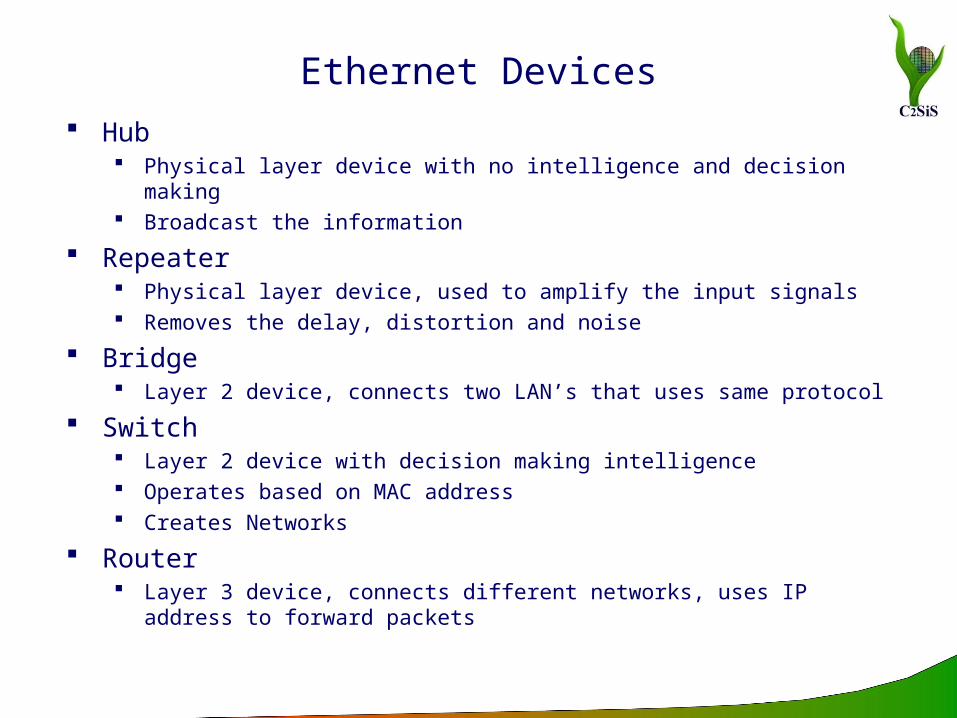
Ethernet Devices Hub
Physical layer device with no intelligence and decision making Broadcast the information
Repeater Physical layer device, used to amplify the input signals Removes the delay, distortion and noise
Bridge Layer 2 device, connects two LAN’s that uses same protocol
Switch Layer 2 device with decision making intelligence Operates based on MAC address Creates Networks
Router Layer 3 device, connects different networks, uses IP address to forward
packets
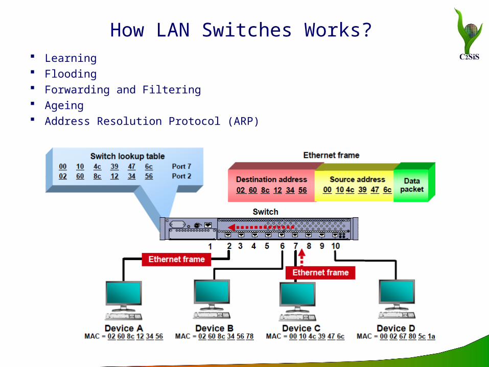
How LAN Switches Works? Learning Flooding Forwarding and Filtering Ageing Address Resolution Protocol (ARP)
Switching Methods Cut through Switching
Developed to reduce the latency inside the switch Forwards the frame as soon as it reads the Destination MAC No error checking
Store and Forward Switching Copies the each complete frame into memory Computes CRC for errors, length check (Short/Jumbo) Outgoing interface is determined by the DA
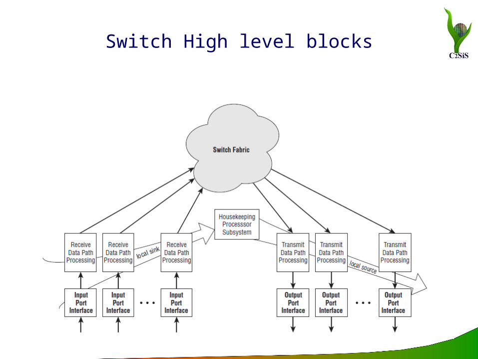
Switch High level blocks
Housekeeping Processor functions
Used to implement control and management functions Typical processors used – MIPS, ARM, PowerPC Spanning Tree Protocol Link Aggregation Control Protocol Marker Protocol Network Management Internal Diagnostics & Maintenance
Device Initialization Power on self test Diagnostics and debug routines ROM code update capability, and so on

Switch – Ingress Path
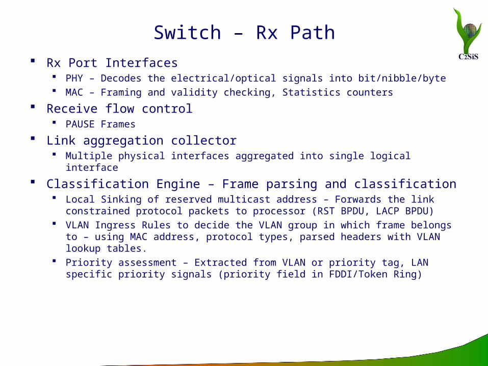
Switch – Rx Path Rx Port Interfaces
PHY – Decodes the electrical/optical signals into bit/nibble/byte MAC – Framing and validity checking, Statistics counters
Receive flow control PAUSE Frames
Link aggregation collector Multiple physical interfaces aggregated into single logical interface
Classification Engine – Frame parsing and classification Local Sinking of reserved multicast address – Forwards the link
constrained protocol packets to processor (RST BPDU, LACP BPDU) VLAN Ingress Rules to decide the VLAN group in which frame belongs
to – using MAC address, protocol types, parsed headers with VLAN lookup tables.
Priority assessment – Extracted from VLAN or priority tag, LAN specific priority signals (priority field in FDDI/Token Ring)
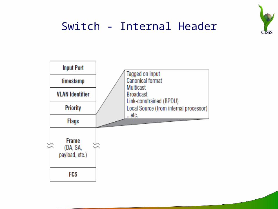
Switch - Internal Header
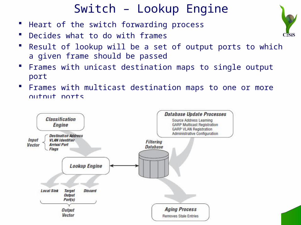
Switch – Lookup Engine Heart of the switch forwarding process Decides what to do with frames Result of lookup will be a set of output ports to which a
given frame should be passed Frames with unicast destination maps to single output port Frames with multicast destination maps to one or more
output ports

Switch - Lookup Engine Implementation Depends on the complexity of lookup operation and the
number and data rate of the ports being supported Content Addressable Memory (CAM) Pseudo CAM – Standard memory (SRAM) with finite state
machine that emulates operation of a CAM Embedded micro engines providing flexible, programmable
lookup under software control Centralized lookup Distributed lookup
Switch Fabrics
Transfers frames among all of the input ports and output ports of the switch
Switch fabric design is critical to the performance of the switch
Switch architectures widely used in commercial LAN switch products Shared Memory Shared Bus Crosspoint Matrix

Switch Fabric – Shared memory architecture
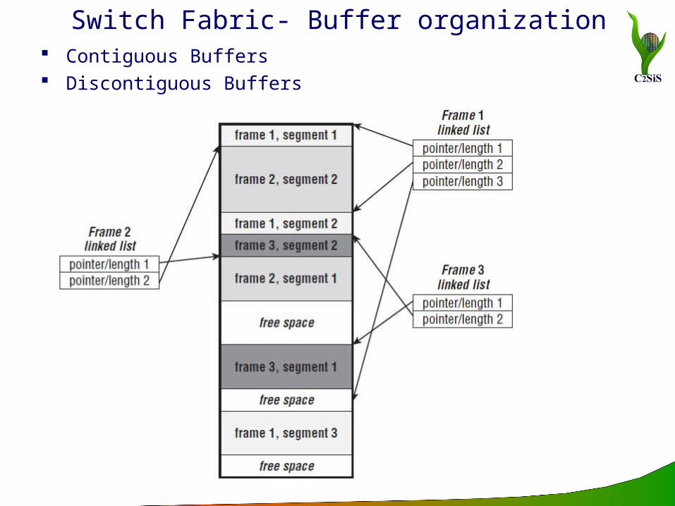
Switch Fabric- Buffer organization Contiguous Buffers Discontiguous Buffers
Switch – Egress Path
Switch - Egress Path
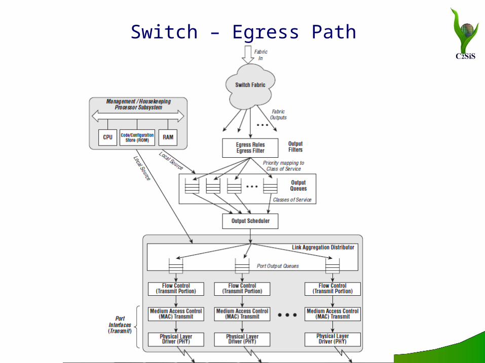
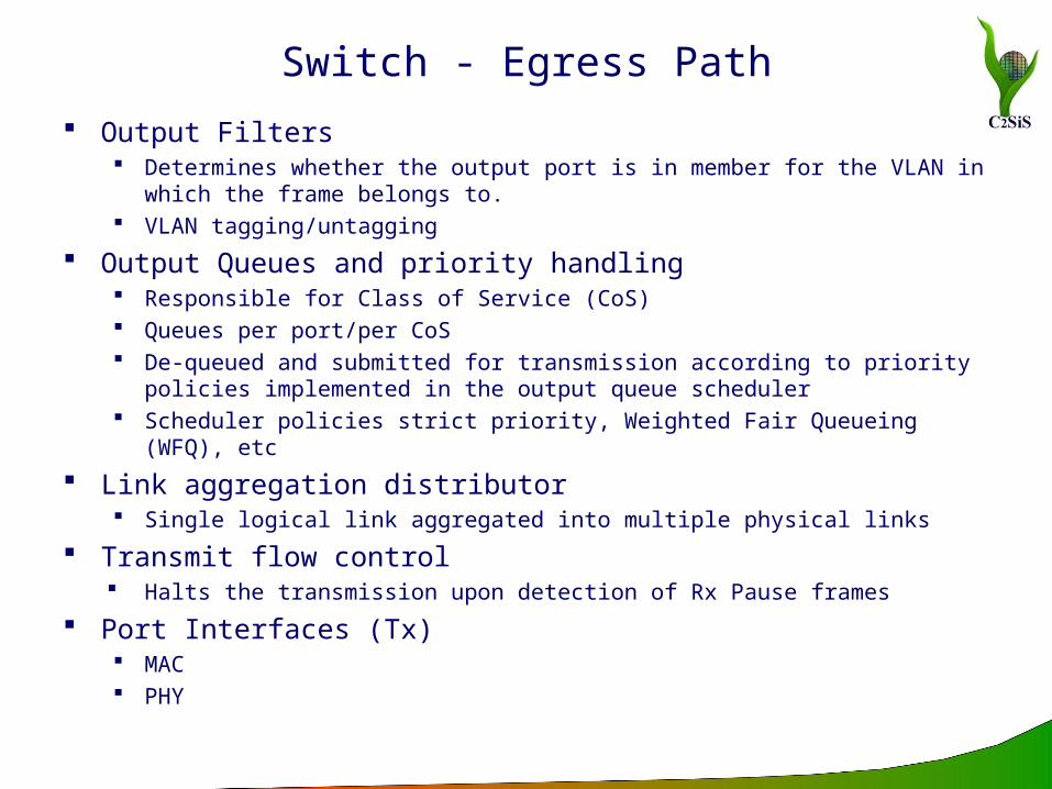
Output Filters Determines whether the output port is in member for the VLAN in
which the frame belongs to. VLAN tagging/untagging
Output Queues and priority handling Responsible for Class of Service (CoS) Queues per port/per CoS De-queued and submitted for transmission according to priority policies
implemented in the output queue scheduler Scheduler policies strict priority, Weighted Fair Queueing (WFQ), etc
Link aggregation distributor Single logical link aggregated into multiple physical links
Transmit flow control Halts the transmission upon detection of Rx Pause frames
Port Interfaces (Tx) MAC PHY

Content Addressable Memory (CAM)
Content Addressable Memory is a special kind of memory!
Read operation in traditional memory: Input is address location of
the content that we are interested in it.
Output is the content of that address.
In CAM it is the reverse: Input is associated with
something stored in the memory.
Output is location where the associated content is stored
1 0 1 X X
0 1 1 0 X
0 1 1 X X
1 0 0 1 1
0 1 1 0 1
0 0
0 1
1 0
1 1
0 1
Content AddressableMemory
1 0 1 X X
0 1 1 0 X
0 1 1 X X
1 0 0 1 1
0 1
0 0
0 1
1 0
1 1
0 1 1 0 X
Traditional Memory
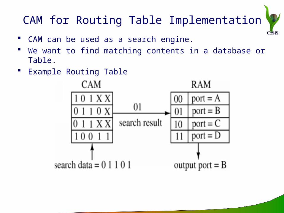
CAM for Routing Table Implementation
CAM can be used as a search engine. We want to find matching contents in a database or Table. Example Routing Table
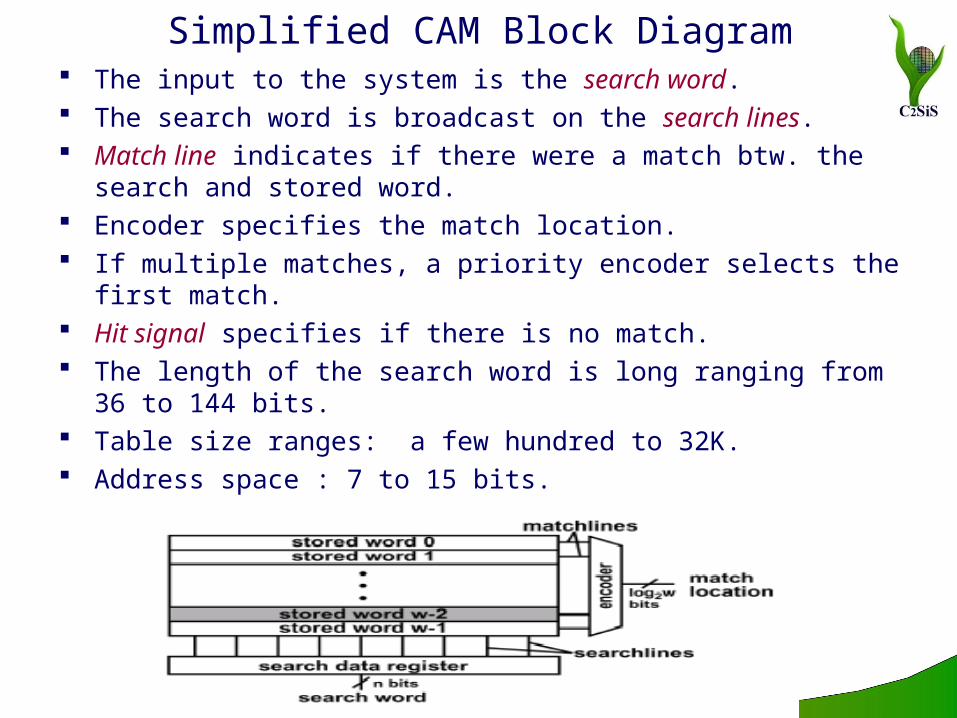
Simplified CAM Block Diagram The input to the system is the search word. The search word is broadcast on the search lines. Match line indicates if there were a match btw. the search
and stored word. Encoder specifies the match location. If multiple matches, a priority encoder selects the first
match. Hit signal specifies if there is no match. The length of the search word is long ranging from 36 to
144 bits. Table size ranges: a few hundred to 32K. Address space : 7 to 15 bits.

CAM Basics
The search-data word is loaded into the search-data register.
All match-lines are pre-charged to high (temporary match state).
Search line drivers broadcast the search word onto the differential search lines.
Each CAM core compares its stored bit against the bit on the corresponding search-lines.
Match words that have at least one missing bit, discharge to ground.
Type of CAMs
Binary CAM (BCAM) only stores 0s and 1s Applications: MAC table consultation. Layer 2 security related VPN
segregation.
Ternary CAM (TCAM) stores 0s, 1s and don’t cares. Application: when we need wilds cards such as, layer 3 and 4
classification for QoS and CoS purposes. IP routing (longest prefix matching).
Available sizes: 1Mb, 2Mb, 4.7Mb, 9.4Mb, and 18.8Mb.
CAM Advantages
They associate the input (comparand) with their memory contents in one clock cycle.
They are configurable in multiple formats of width and depth of search data that allows searches to be conducted in parallel.
CAM can be cascaded to increase the size of lookup tables that they can store.
They are one of the appropriate solutions for higher speeds.
CAM Disadvantages
They cost several hundred of dollars per CAM even in large quantities.
They occupy a relatively large footprint on a card. They consume excessive power. Generic system engineering problems:
Interface with network processor. Simultaneous table update and looking up requests
Alternative Hardware Implementations Tree search Hashing Algorithms

L2 Protocols
LLDP (Link Layer Discovery Protocol) VLAN STP/RSTP/MSTP FDDI Frame Relay HDLC WiFi WiMAX PPP Token Ring VTP (VLAN Trunking Protocol)
Link Layer Discovery Protocol (LLDP)
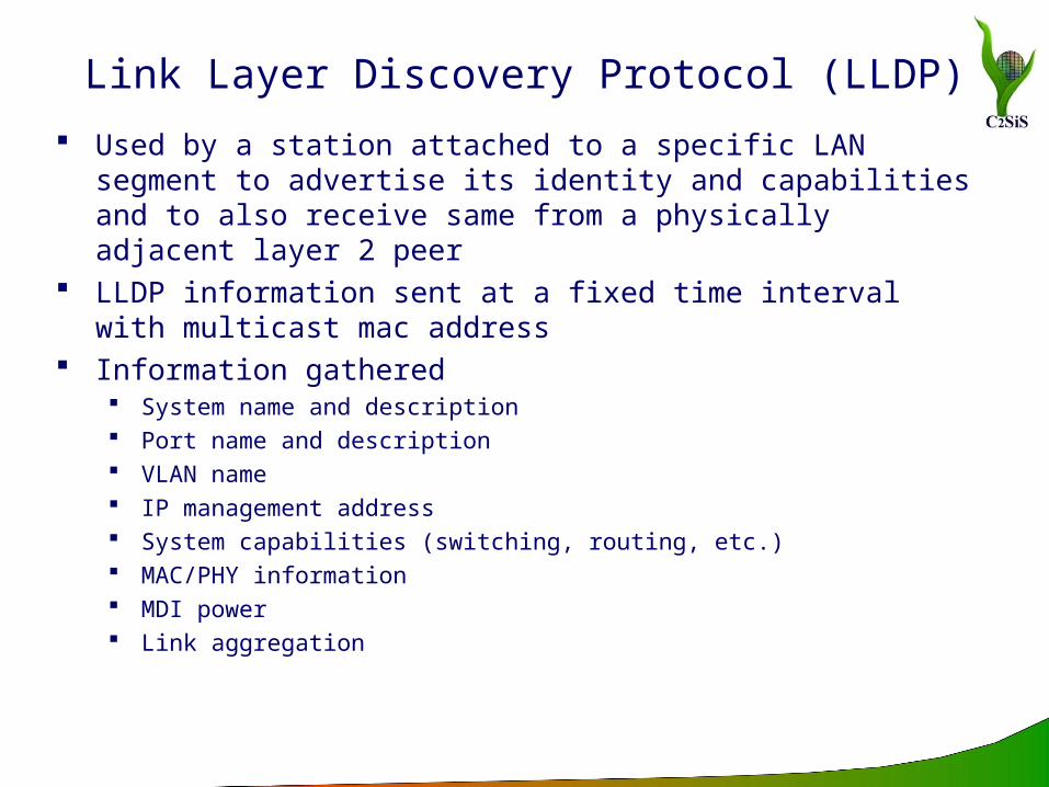
Used by a station attached to a specific LAN segment to advertise its identity and capabilities and to also receive same from a physically adjacent layer 2 peer
LLDP information sent at a fixed time interval with multicast mac address
Information gathered System name and description Port name and description VLAN name IP management address System capabilities (switching, routing, etc.) MAC/PHY information MDI power Link aggregation
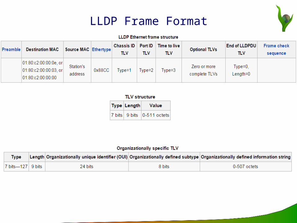
LLDP Frame Format
Virtual Local Area Network (VLAN)
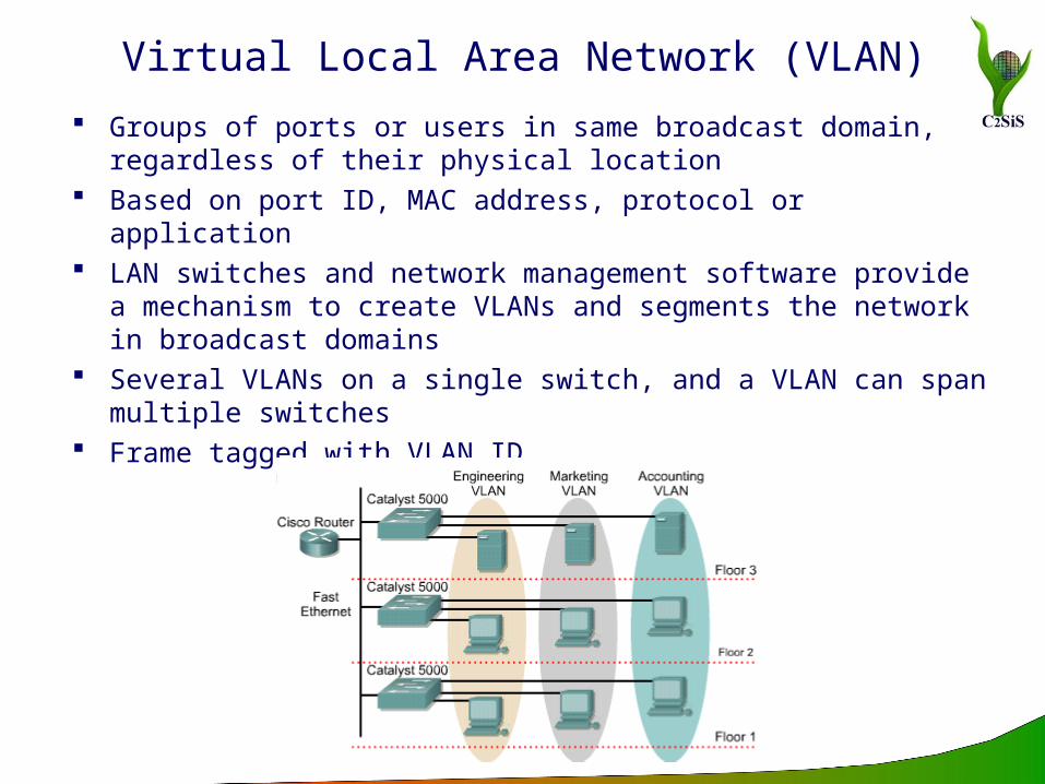
Groups of ports or users in same broadcast domain, regardless of their physical location
Based on port ID, MAC address, protocol or application LAN switches and network management software provide a
mechanism to create VLANs and segments the network in broadcast domains
Several VLANs on a single switch, and a VLAN can span multiple switches
Frame tagged with VLAN ID
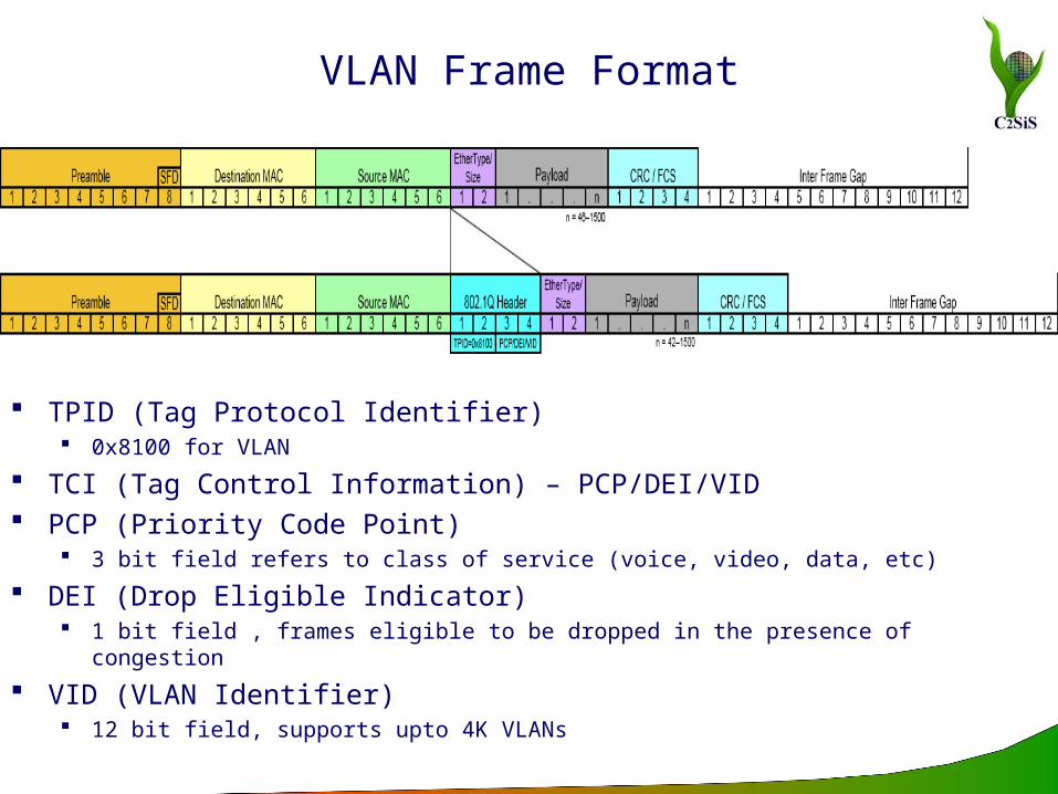
VLAN Frame Format
TPID (Tag Protocol Identifier) 0x8100 for VLAN
TCI (Tag Control Information) – PCP/DEI/VID PCP (Priority Code Point)
3 bit field refers to class of service (voice, video, data, etc)
DEI (Drop Eligible Indicator) 1 bit field , frames eligible to be dropped in the presence of congestion
VID (VLAN Identifier) 12 bit field, supports upto 4K VLANs

Spanning Tree Protocol (STP)
To prevent network loops To introduce redundancy in the link connections (if one link
fails, the data is still routed through a different link/route)
STP/RSTP/MSTP Electing the root Link costs BPDU Messages (Bridge Protocol Data Units) Rapid Spanning Tree Protocol (RSTP)
Network reconfiguration in ~5 seconds Discarding - Does not accept/ forward any data but listens to BPDU
messages Learning - Once the network topology change is detected/ activation
request comes via the BPDU message and filtering/ forwarding table creation is initiated
Forwarding - RTSP ports start accepting and forwarding data packets/ frames
Multiple Spanning Tree Protocol (MSTP) Load balancing in networks

RSTP BPDU Format

Thank You!!!