Data Communications & Computer Networks Lecture 7...
26
ACOE312 Data Link Control 1 Data Communications & Computer Networks Lecture 7 Data Link Control Fall 2006 Agenda • Preface • Flow Control —Stop-and-wait —Sliding Window • Error Control —Stop-and-wait ARQ —Go-back-N ARQ —Selective-reject ARQ • Performance issues • Home Exercises
Transcript of Data Communications & Computer Networks Lecture 7...
ACOE312 Data Link Control 1
Data Communications &
Computer Networks
Lecture 7
Data Link Control
Fall 2006
Agenda
• Preface
• Flow Control
—Stop-and-wait
—Sliding Window
• Error Control
—Stop-and-wait ARQ
—Go-back-N ARQ
—Selective-reject ARQ
• Performance issues
• Home Exercises

ACOE312 Data Link Control 2
Key points
• Because of the possibility of transmission errors and because the receiver may need to control the rate at which data arrive, synchronization and interfacing techniques are not sufficient.
• It is necessary to have a layer of control in each communicatingdevice that provides functions such as flow control, error detection, and error correction.
• This layer of control is known as a Data Link Control Protocol.
• Flow control enables a receiver to regulate the flow of data from a sender so that the receiver is not overwhelmed.
• In a data link control protocol, error control is achieved by retransmission of damaged frames that have not being acknowledged or for which the other side requests a retransmission.
Preface

ACOE312 Data Link Control 3
Preface
• Our discussion so far has concerned sending signals over a transmission link
• For effective digital data communication much more is needed to control and manage the exchange
• In this lecture we shift the emphasis to that of sending data over a data communications link
• To achieve necessary control, a layer of logic is added above the physical interfacing discussed in lecture 6
• This logic is referred to as data link control or data link control protocol
• When a data link control protocol is used, the transmission medium between systems is referred to as data link
Data Link Layer
Application
Presentation
Session
transport
Network
Data link
Physical
Application
Presentation
Session
transport
Network
Data link
Physical
Network
Data link
Physical
Source node Destination node
Intermediate node
Signals
Packets
Bits
Frames
L7
L6
L5
L4
L3
L2
L1
ACOE312 Data Link Control 4
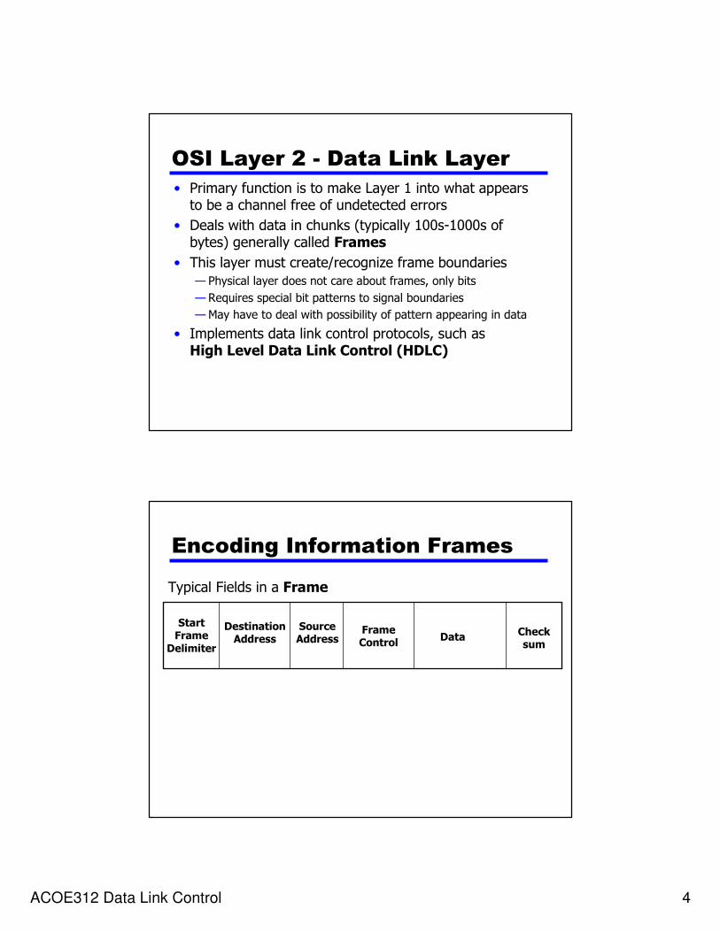
OSI Layer 2 - Data Link Layer
• Primary function is to make Layer 1 into what appears to be a channel free of undetected errors
• Deals with data in chunks (typically 100s-1000s of bytes) generally called Frames
• This layer must create/recognize frame boundaries
— Physical layer does not care about frames, only bits
— Requires special bit patterns to signal boundaries
— May have to deal with possibility of pattern appearing in data
• Implements data link control protocols, such as High Level Data Link Control (HDLC)
Encoding Information Frames
Typical Fields in a Frame
StartFrame
Delimiter
SourceAddress
DestinationAddress
FrameControl
DataChecksum

ACOE312 Data Link Control 5
DLL Operation
NetworkLayer
Data Link Layer
Physical Layer
Retransmit
if timeout
ACK if
correctFrame
CRC
ACK
CRC
Sender Receiver
correct and ordered
Data Link Layer Services
• Flow Control:—pacing between senders and receivers
• Error Detection:
—errors are caused by signal attenuation and noise.
—Receiver detects presence of errors:
• it signals the sender for retransmission or just drops the corrupted frame
• Error Correction:
—mechanism for the receiver to locate and correct the error without resorting to retransmission

ACOE312 Data Link Control 6
Flow Control
1. Flow Control
• Flow control is a technique for ensuring that the sending entity does not overwhelm the receiving entity with data
— Preventing buffer overflow
• Transmission time
—Time taken for a station to emit all bits of a frame into medium
• Proportional to the length of the frame
• Propagation time
—Time for a bit to traverse the link between source and destination
ACOE312 Data Link Control 7
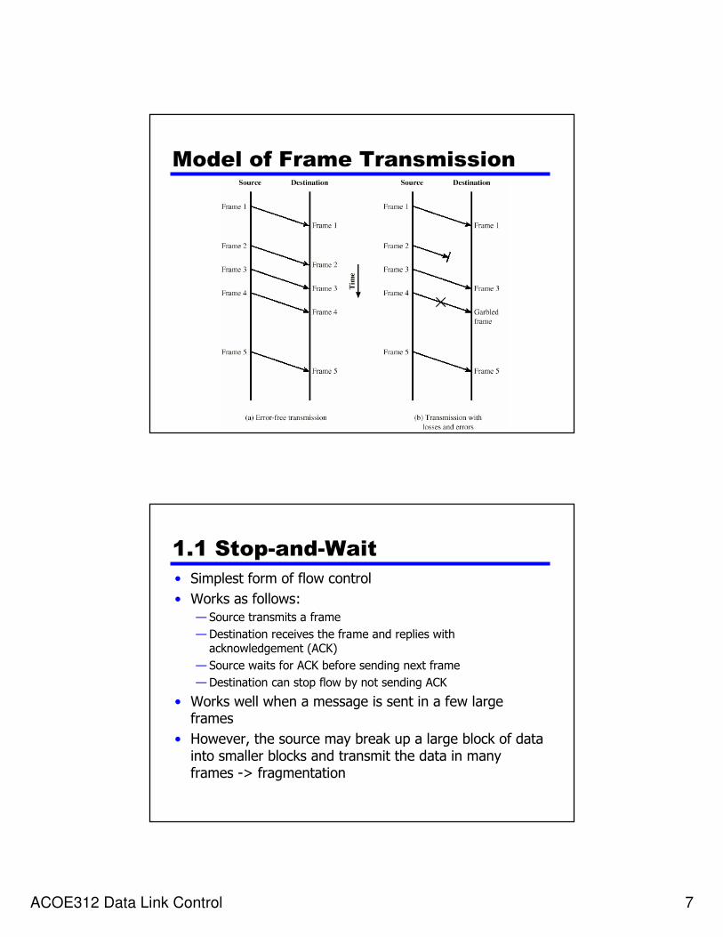
Model of Frame Transmission
1.1 Stop-and-Wait
• Simplest form of flow control
• Works as follows:
— Source transmits a frame
— Destination receives the frame and replies with acknowledgement (ACK)
— Source waits for ACK before sending next frame
— Destination can stop flow by not sending ACK
• Works well when a message is sent in a few large frames
• However, the source may break up a large block of data into smaller blocks and transmit the data in many frames -> fragmentation

ACOE312 Data Link Control 8
Fragmentation
• Large block of data may be split into small frames. The reasons are:
—Limited buffer size of the receiver
—Errors detected sooner with smaller frames (the longest the transmission, the more likely there will be an error)
—On error, retransmission of smaller frames is needed
—Prevents one station occupying medium for long periods
• Stop-and-wait becomes inadequate with the use of multiple frames for a single message
—Only one frame at a time can be in transit
Bit length of a link
B = R (d/V)where, B= length of the link in bits (this is the number of bits present on the
link when a stream of bits fully occupies the link)
R = data rate of the link, in bps
d = length, or distance of the link in meters
V = velocity of propagation in m/s
If B>frame length, there are serious inefficiencies (see next slide)
In the figure of next slide, assume that
transmission time = 1 and propagation delay, a = B/Lwhere L = length of the frame in bits
• When a<1, frame is sufficiently long that the first bits of the frame have arrived at the destination before the source has completed the transmission of the frame
• When a>1, the sender completes transmission of the entire frame before the leading bits of that frame arrive at the receiver.
ACOE312 Data Link Control 9
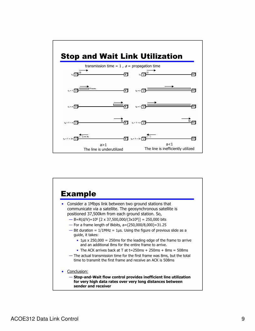
Stop and Wait Link Utilizationtransmission time = 1 , a = propagation time
a>1The line is underutilized
a<1The line is inefficiently utilized
Example
• Consider a 1Mbps link between two ground stations that communicate via a satellite. The geosynchronous satellite is positioned 37,500km from each ground station. So,
— B=R(d/V)=106 [2 x 37,500,000/(3x108)] = 250,000 bits
— For a frame length of 8kbits, a=(250,000/8,000)=31.25
— Bit duration = 1/1MHz = 1µs. Using the figure of previous slide as a guide, it takes:
• 1µs x 250,000 = 250ms for the leading edge of the frame to arrive and an additional 8ms for the entire frame to arrive.
• The ACK arrives back at T at t=250ms + 250ms + 8ms = 508ms
— The actual transmission time for the first frame was 8ms, but the total time to transmit the first frame and receive an ACK is 508ms
• Conclusion:
— Stop-and-Wait flow control provides inefficient line utilization for very high data rates over very long distances between sender and receiver
ACOE312 Data Link Control 10
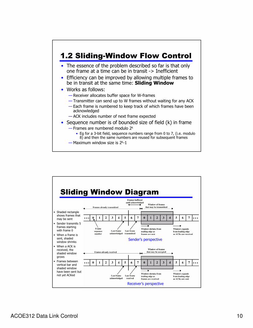
1.2 Sliding-Window Flow Control
• The essence of the problem described so far is that only one frame at a time can be in transit -> Inefficient
• Efficiency can be improved by allowing multiple frames to be in transit at the same time: Sliding Window
• Works as follows:—Receiver allocates buffer space for W-frames
— Transmitter can send up to W frames without waiting for any ACK
— Each frame is numbered to keep track of which frames have been acknowledged
— ACK includes number of next frame expected
• Sequence number is of bounded size of field (k) in frame— Frames are numbered modulo 2k
• Eg for a 3-bit field, sequence numbers range from 0 to 7, (i.e. modulo 8) and then the same numbers are reused for subsequent frames
—Maximum window size is 2k-1
Sliding Window Diagram
Sender’s perspective
Receiver’s perspective
• Shaded rectangle shows frames that may be sent
• Sender transmits 5 frames starting with frame 0
• When a frame is sent, shaded window shrinks
• When a ACK is received, the shaded window grows
• Frames between vertical bar and shaded window have been sent but not yet ACKed
ACOE312 Data Link Control 11
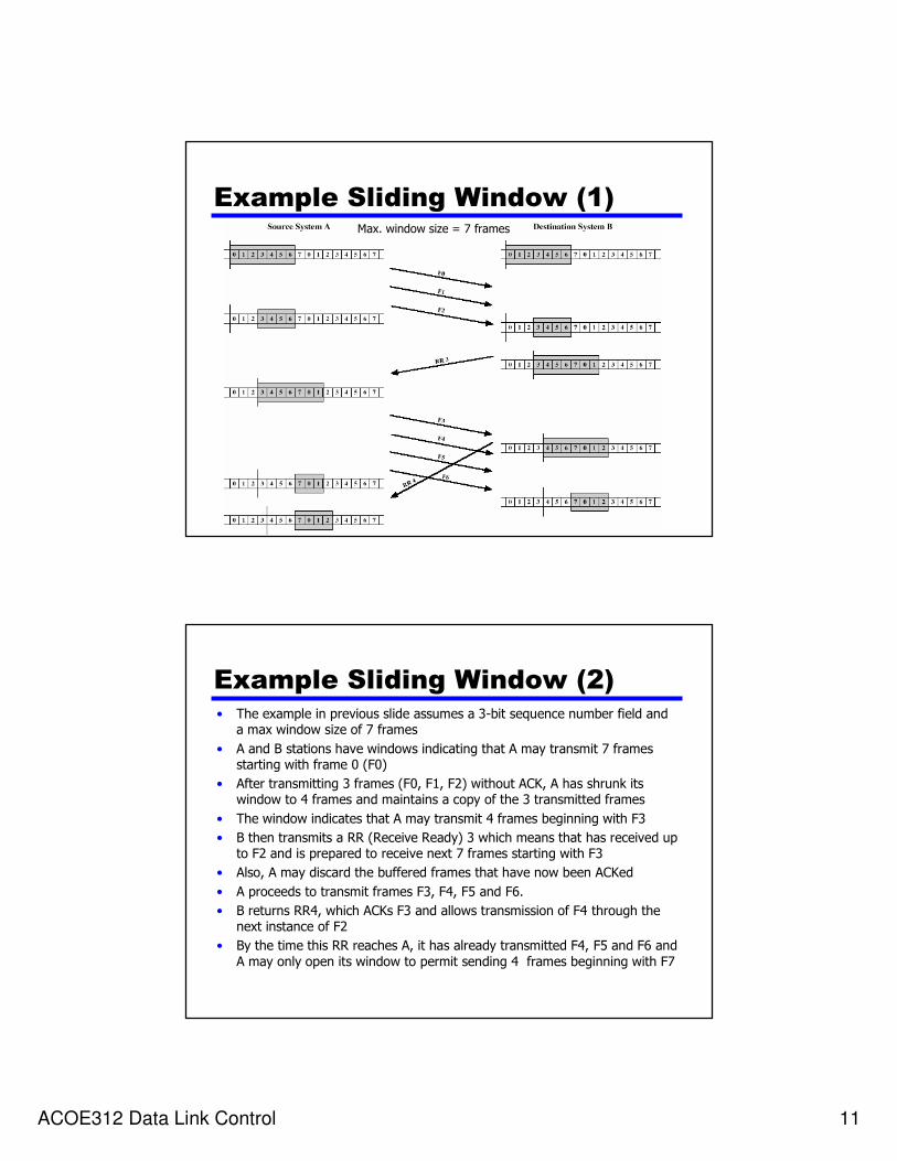
Example Sliding Window (1)Max. window size = 7 frames
Example Sliding Window (2)• The example in previous slide assumes a 3-bit sequence number field and
a max window size of 7 frames
• A and B stations have windows indicating that A may transmit 7 frames starting with frame 0 (F0)
• After transmitting 3 frames (F0, F1, F2) without ACK, A has shrunk its window to 4 frames and maintains a copy of the 3 transmitted frames
• The window indicates that A may transmit 4 frames beginning with F3
• B then transmits a RR (Receive Ready) 3 which means that has received up to F2 and is prepared to receive next 7 frames starting with F3
• Also, A may discard the buffered frames that have now been ACKed
• A proceeds to transmit frames F3, F4, F5 and F6.
• B returns RR4, which ACKs F3 and allows transmission of F4 through the next instance of F2
• By the time this RR reaches A, it has already transmitted F4, F5 and F6 and
A may only open its window to permit sending 4 frames beginning with F7
ACOE312 Data Link Control 12
Sliding Window visualization
The following link contains a nice simulation that may help you visualize the concept of sliding window. They require ShockWave plug-ins and a reasonably up-to-date internet browser
http://www.humboldt.edu/~aeb3/telecom/SlidingWindow.html
Note: You can download Shockwave for free from Macromedia’s Shockwave Player Download Centre athttp://www.macromedia.com
Sliding Window Enhancements• So far we have discussed transmission in one direction only
— Both stations need to maintain two windows, one for transmit and one for receive
— Each side needs to send the data and acknowledgements to the other
• Receiver can acknowledge frames without permitting further transmission (Receive Not Ready)
— Must send a normal acknowledge to resume
• If duplex operation, use piggybacking, ie temporarily delay outgoing ACKs so that they can be hooked onto the next outgoing data frame.
— If a station has no data to send, it sends a separate acknowledgement frame
— If a station has data to send but no acknowledgement to send, then it sends last acknowledgement number again
— If a station has data to send and an acknowledgement to send, then it sends both together in one frame, saving bandwidth
ACOE312 Data Link Control 13
Comparison between stop-and-
wait and sliding window• Sliding window is more efficient
—With sliding window, the transmission link is treated as a pipeline that may be filled with frames in transit
—With stop-and-wait flow control, only one frame may be in the pipe at a time
• For the previous example (satellite configuration), it was found that it takes 508ms for an ACK to the first frame to be received.
— It takes 8ms to transmit one frame, so the sender can transmit 64 frames by the time the ACK to the first frame is received
— If window size is 6bits or more (26=64 frames), the sender can transmit continuously, or a rate of 1 frame every 8ms
— If window size is 7 frames using a 3-bit window field, then the sender can only send 7 frames and then must wait for an ACK before sending more. In this case, the sender can transmit at a rate of 7 frames per 508ms, or 1 frame every 72.6ms. With stop-and-wait, a rate of only one frame per 508ms is possible.
Error Control

ACOE312 Data Link Control 14
2. Error Control• Error control refers to mechanisms to detect and correct errors that
occur in the transmission of frames
• Data are sent as a sequence of frames. Two types of errors can occur:
— Lost frames (failing to arrive at the other side)
— Damaged frames (frame does arrive but some bits are in error)
• The most common techniques for error control are based on:
— Error detection
• discussed in lecture 6
— Positive acknowledgment
• to successfully received frames
— Retransmission after timeout
• source retransmits frame that has not been acknowledged after a predetermined amount of time
—Negative acknowledgement and retransmission
• to frames in which an error has been detected. Source then retransmits those frames
Automatic Repeat Request
(ARQ)
• The error control techniques stated in the previous slide are referred to as Automatic Repeat Request (ARQ)
• The effect of ARQ is to make an unreliable data link, a reliable one.
• Three versions of ARQ
—Stop-and-wait ARQ
—Go-back-N ARQ
—Selective-reject ARQ (selective retransmission)

ACOE312 Data Link Control 15
2.1 Stop-and-Wait ARQ
• Based on the stop-and-wait flow control technique. Works as follows:
— Source station transmits a single frame
—Waits for ACK
— No other data frames can be sent until the destination station’s reply arrives at the source station
— Two types of errors could occur
• If the received frame is damaged, it discards it
– Transmitter has timeout
– If no ACK within timeout, retransmit
• If ACK is damaged, transmitter will not recognize it
– Transmitter will retransmit frame
– Receiver gets two copies of the frame
– To avoid this problem, frames are labeled with ACK0 and ACK1
Stop and Wait -
Diagram
• The figure shows the two types of errors described in the previous slide.
• The 3rd frame transmitted by A is lost or damaged and therefore no ACK is returned to B.
• A times out and retransmits the frame
• Later, A transmits a frame labeled 1 but the ACK0 for that frame is lost.
• A times out and retransmits the same frame.
• When B receives 2 frames in a row with the same label, it discards the 2nd
frame but sends back an ACK0 to each.

ACOE312 Data Link Control 16
Stop and Wait - Pros and Cons
• Advantage: Simple
• Disadvantage: Inefficient
2.2 Go-Back-N ARQ
• Based on sliding window
• If no errors in frame, destination sends ACK as usual with next frame expected
• Use window to control number of outstanding frames
• If error in frame, destination replies with rejection REJ (= -ve ACK)—Destination station discards that frame and all future frames until error frame is received correctly
—When the transmitter receives the REJ must go back and retransmit that frame and all subsequent frames

ACOE312 Data Link Control 17
Cases considered by Go-back-n
• Damaged frame
• Lost frame
• Damaged acknowledgement (ACK)
• Damaged Rejection (REJ)
Go Back N
Damaged Frame case
• Suppose transmitter sends frames to receiver. Receiver has previously successfully received frame (i -1) and transmitter has just transmitted frame i .
—If receiver detects error in frame i, it discards the frame and it sends REJ-i to transmitter
—Transmitter gets REJ-i and retransmits frame i and all subsequent frames

ACOE312 Data Link Control 18
Go Back N
Lost Frame case (1)
• Frame i is lost
• Transmitter sends next frame (i +1)
• Receiver gets frame (i +1) out of sequence
• Receiver sends reject REJ- i
• Transmitter goes back to frame i and retransmits
Go Back N
Lost Frame case (2)
• Frame i is lost and no additional frame is sent
• Receiver gets nothing and returns neither acknowledgement nor rejection
• Transmitter times out and sends acknowledgement frame with P-bit set to 1
• Receiver interprets this as command which it acknowledges with the number of the next frame it expects (frame i )
• Transmitter then retransmits frame i

ACOE312 Data Link Control 19
Go Back N
Damaged ACK case
• Receiver gets frame i and sends acknowledgement (i +1) which is lost
• Acknowledgements are cumulative, so next acknowledgement (i +n) may arrive before transmitter times out on frame i
• If transmitter times out, it sends acknowledgement with P bit set as before
• This can be repeated a number of times before a reset procedure is initiated
Go Back N
Damaged Rejection case
• Similar to Lost Frame case (2)
ACOE312 Data Link Control 20
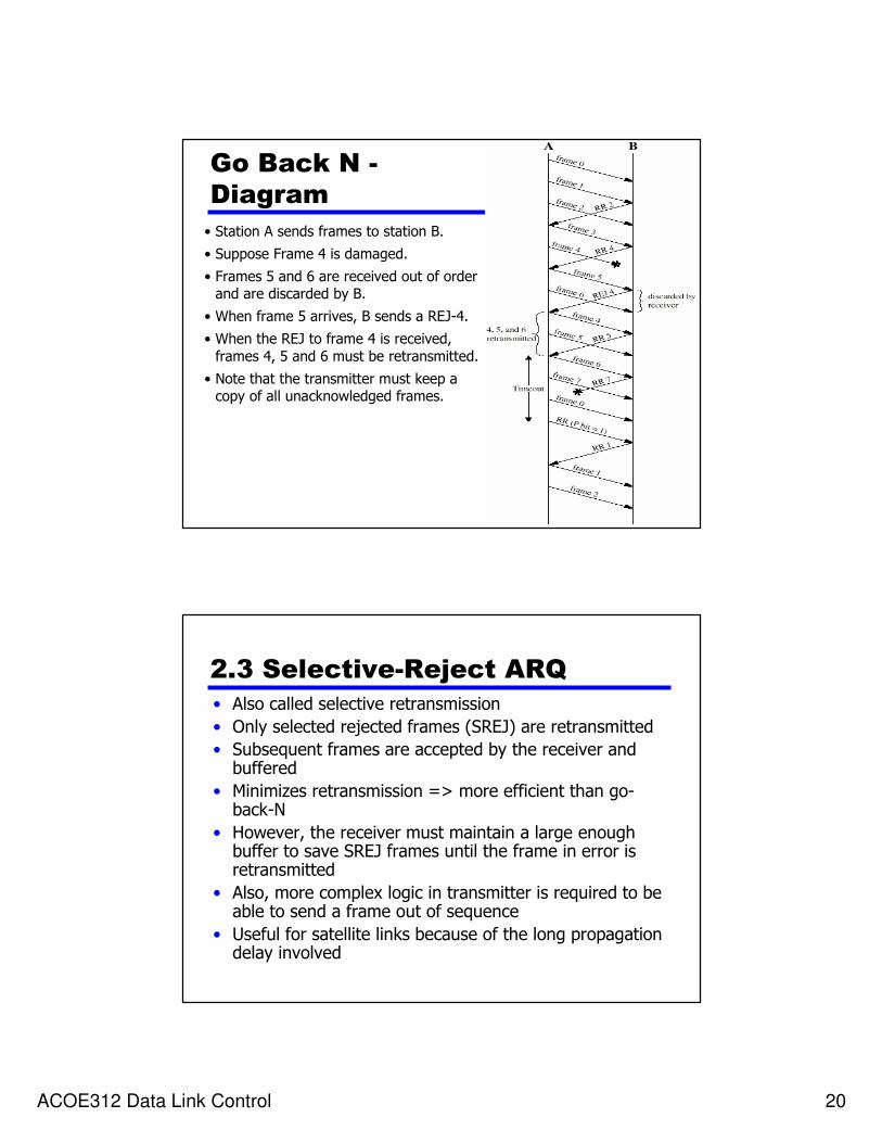
Go Back N -
Diagram
• Station A sends frames to station B.
• Suppose Frame 4 is damaged.
• Frames 5 and 6 are received out of order and are discarded by B.
• When frame 5 arrives, B sends a REJ-4.
• When the REJ to frame 4 is received,
frames 4, 5 and 6 must be retransmitted.
• Note that the transmitter must keep a copy of all unacknowledged frames.
2.3 Selective-Reject ARQ
• Also called selective retransmission
• Only selected rejected frames (SREJ) are retransmitted
• Subsequent frames are accepted by the receiver and buffered
• Minimizes retransmission => more efficient than go-back-N
• However, the receiver must maintain a large enough buffer to save SREJ frames until the frame in error is retransmitted
• Also, more complex logic in transmitter is required to be able to send a frame out of sequence
• Useful for satellite links because of the long propagation delay involved
ACOE312 Data Link Control 21
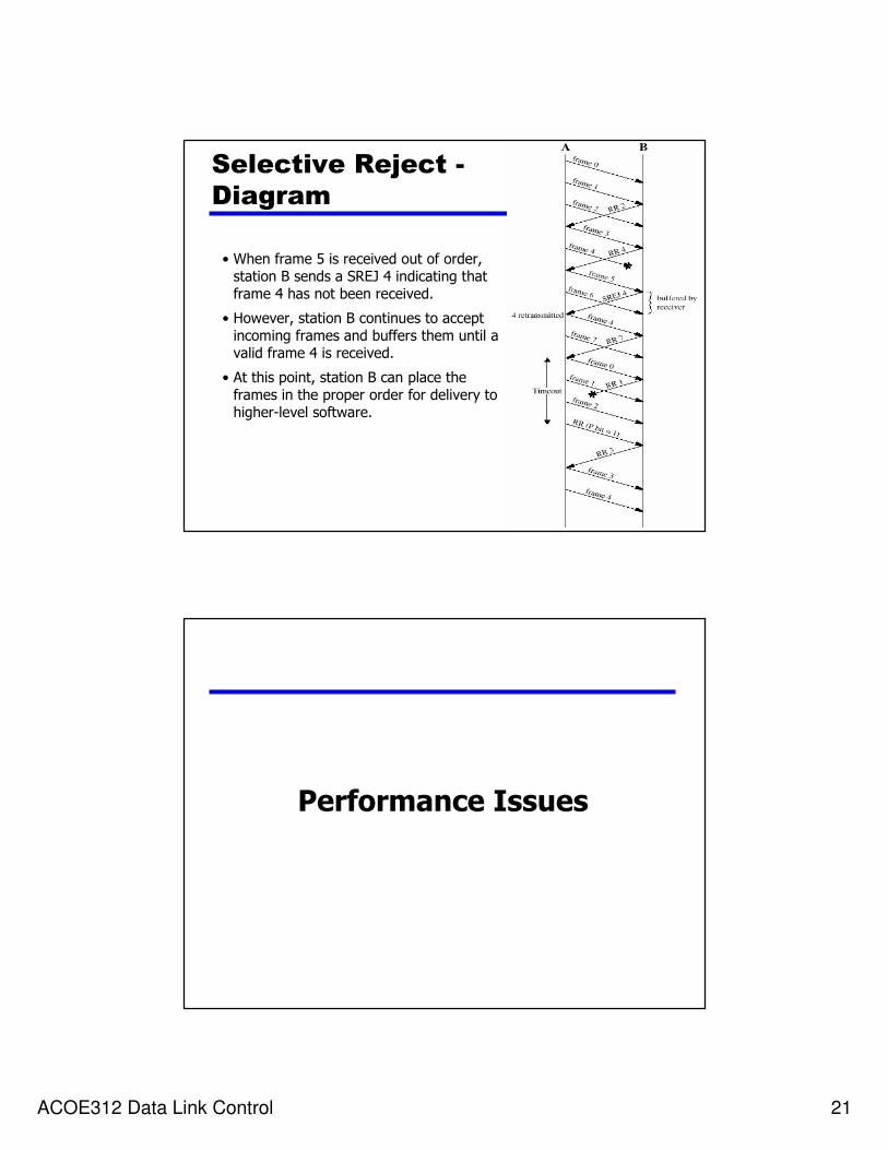
Selective Reject -
Diagram
• When frame 5 is received out of order, station B sends a SREJ 4 indicating that frame 4 has not been received.
• However, station B continues to accept incoming frames and buffers them until a valid frame 4 is received.
• At this point, station B can place the frames in the proper order for delivery to higher-level software.
Performance Issues
ACOE312 Data Link Control 22
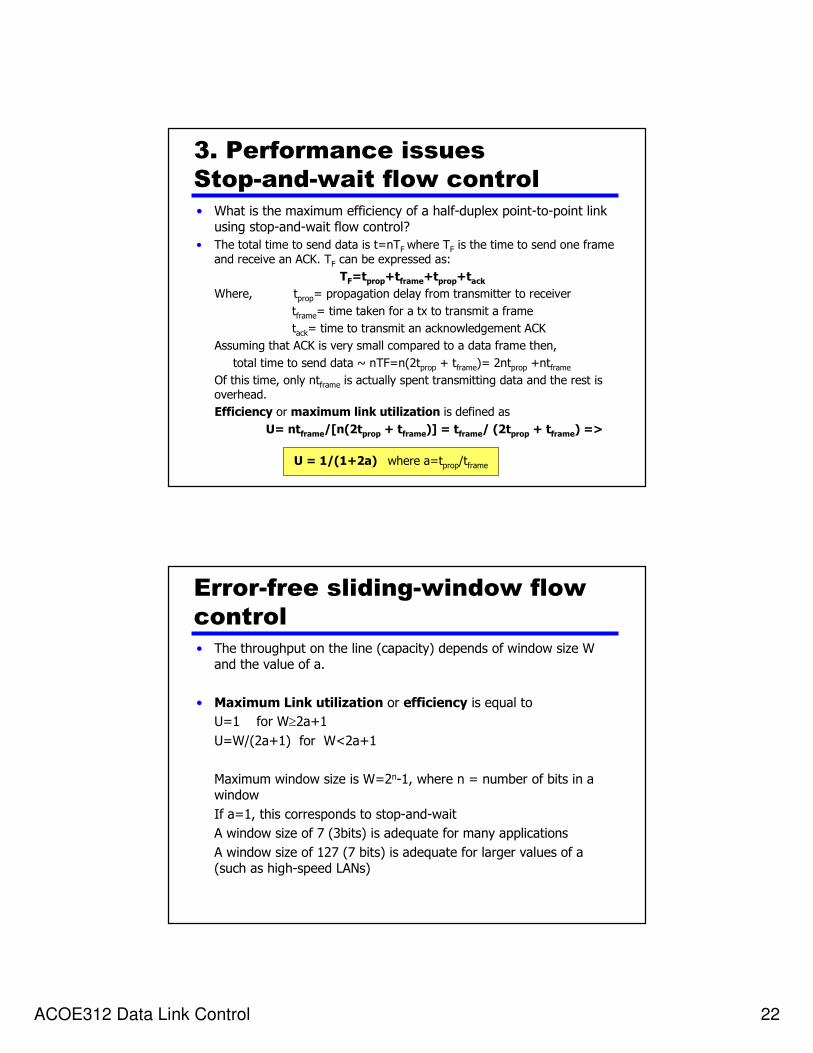
3. Performance issues
Stop-and-wait flow control
• What is the maximum efficiency of a half-duplex point-to-point link using stop-and-wait flow control?
• The total time to send data is t=nTF where TF is the time to send one frame
and receive an ACK. TF can be expressed as:
TF=tprop+tframe+tprop+tack
Where, tprop= propagation delay from transmitter to receiver
tframe= time taken for a tx to transmit a frame
tack= time to transmit an acknowledgement ACK
Assuming that ACK is very small compared to a data frame then,
total time to send data ~ nTF=n(2tprop + tframe)= 2ntprop +ntframe
Of this time, only ntframe is actually spent transmitting data and the rest is overhead.
Efficiency or maximum link utilization is defined as
U= ntframe/[n(2tprop + tframe)] = tframe/ (2tprop + tframe) =>
U = 1/(1+2a) where a=tprop/tframe
Error-free sliding-window flow
control
• The throughput on the line (capacity) depends of window size W and the value of a.
• Maximum Link utilization or efficiency is equal to
U=1 for W≥2a+1
U=W/(2a+1) for W<2a+1
Maximum window size is W=2n-1, where n = number of bits in a window
If a=1, this corresponds to stop-and-wait
A window size of 7 (3bits) is adequate for many applications
A window size of 127 (7 bits) is adequate for larger values of a(such as high-speed LANs)

ACOE312 Data Link Control 23
Required Reading
• Stallings chapter 7
Home Exercises
ACOE312 Data Link Control 24
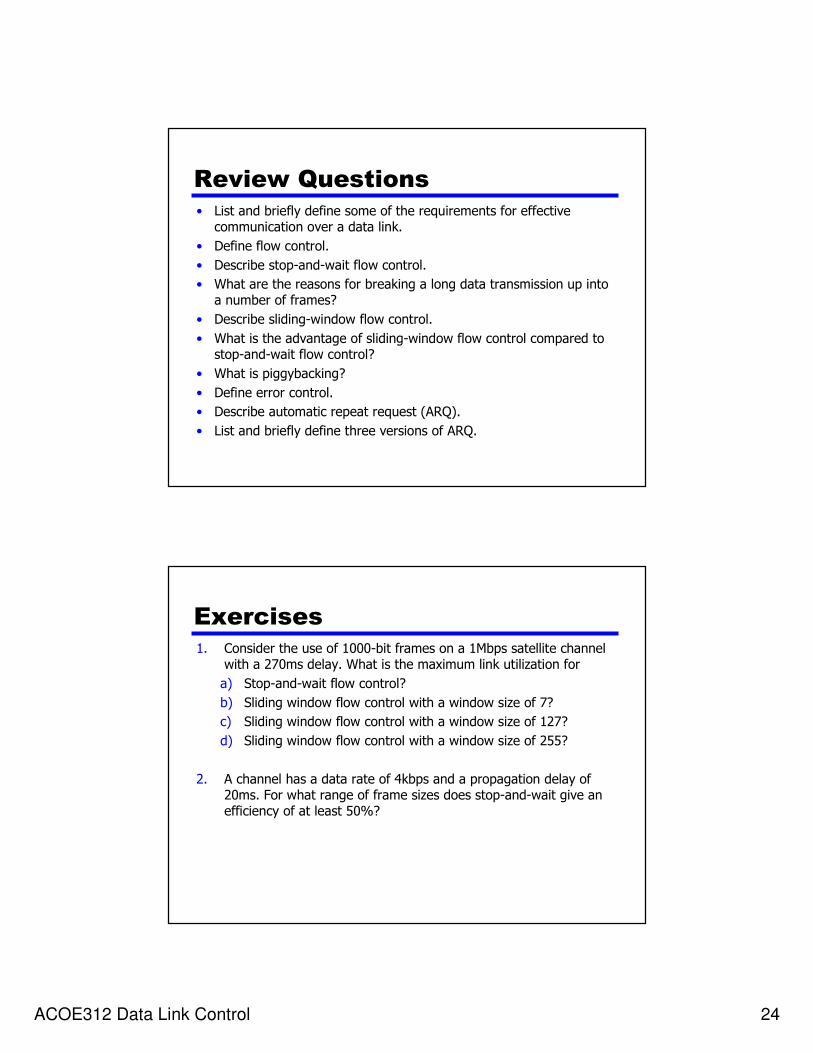
Review Questions
• List and briefly define some of the requirements for effective communication over a data link.
• Define flow control.
• Describe stop-and-wait flow control.
• What are the reasons for breaking a long data transmission up into a number of frames?
• Describe sliding-window flow control.
• What is the advantage of sliding-window flow control compared to stop-and-wait flow control?
• What is piggybacking?
• Define error control.
• Describe automatic repeat request (ARQ).
• List and briefly define three versions of ARQ.
Exercises
1. Consider the use of 1000-bit frames on a 1Mbps satellite channel with a 270ms delay. What is the maximum link utilization for
a) Stop-and-wait flow control?
b) Sliding window flow control with a window size of 7?
c) Sliding window flow control with a window size of 127?
d) Sliding window flow control with a window size of 255?
2. A channel has a data rate of 4kbps and a propagation delay of 20ms. For what range of frame sizes does stop-and-wait give an efficiency of at least 50%?

ACOE312 Data Link Control 25
Solution (1)
1. It is given that
Frame=1000 bits,
Channel data rate = 1Mbps,
Propagation delay = 270ms
(a) Maximum link utilization with stop-and-wait flow control:
U = 1/(1+2a) where a=tprop/tframe
Since tprop=270ms, in order to find the value of U we need to calculate tframe. Since frame = 1000 bits and
Max bit rate=channel data rate = 1Mbps, then
tframe= 1000/106=1ms. So, a= tprop/tframe = 270
So, U = 1/(1+2a) = 1/(1+2x270)=1.85x10-3 = 0.185%
Solution (2)(b) Maximum link utilization with window flow control of window size 7:
Maximum link utilization for window flow control is
U=1 for W≥2a+1
U=W/(2a+1) for W<2a+1
Since W=7 and a=270 then (2a+1)=541, which means that W<2a+1
So, U=W/(2a+1)= 7/541 = 0.013 = 1.3%
(c) Maximum link utilization with window flow control of window size127:
Since W=127 then (2a+1)=541, which means that W<2a+1
So, U=W/(2a+1)= 127/541 = 0.235 = 23.5%
(d) Maximum link utilization with window flow control of window size 255:
Since W=255 then (2a+1)=541, which means that W<2a+1
So, U=W/(2a+1)= 255/541 = 0.471 = 47.1%

ACOE312 Data Link Control 26
Solution (3)2. A channel has a data rate of 4kbps and a propagation delay of 20ms. For what range of frame sizes does stop-and-wait give an efficiency of at least 50%?
It is given that data rate = 4kbps, hence bit duration = 1/4000 =0.25ms
Time to transmit the frame is
tframe= frame_size/Bit rate = frame_size x bit_duration
Also, tprop=20ms. For stop-and-wait flow control, efficiency is equal to
U = 1/(1+2a) where a=tprop/tframe
Solving this equation with respect to a, yields a=0.5[(1/U) – 1]
For U ≥ 50%=0.5, then a ≤ 0.5[(1/0.5) –1] => a ≤0.5
Since a=tprop/tframe then tprop/tframe ≤0.5 => tframe ≥ 2tpropBut frame_size = tframe/bit_duration =>
Frame_size ≥ 2tprop/bit_duration = 2 x 20ms/0.25ms =160
So, in order to have an efficiency of at least 50%, frame size must be at least 160 bits long.