DATA AIRE SERIES - cfconsult.net
40
DATA AIRE SERIES Operation and Maintenance Manual DX 6-30 ton Air and Water/Glycol Cooled INSTALLATION OPERATION MAINTENANCE
Transcript of DATA AIRE SERIES - cfconsult.net

DATA AIRE SERIESOperation and Maintenance Manual
DX 6-30 ton
Air and Water/Glycol Cooled
INSTALLATIONOPERATIONMAINTENANCE
2
CONGRATULATIONS ON THE SELECTION OF A DATA AIRE PRECISIONENVIRONMENTAL CONTROL SYSTEM. PROPER INSTALLATION, OPERATIONAND MAINTENANCE OF THIS EQUIPMENT WILL ENSURE YEARS OF OPTIMALPERFORMANCE.
This manual is intended to assist trained service personnel by providingnecessary guidelines for this particular equipment. Service to Data Aire unitsshould be done by qualified individuals with an adequate background inareas such as HVAC, electrical, plumbing and electronics, as applicable.
Service performed by unauthorized or unqualified technicians may voidmanufacturers’ warranties and could result in property damage and/orpersonal injury.
Special care should be given to those area where these symbols appear.
Data Aire, Inc. reserves the right to make design changes for the purposesof product improvement, or to withdraw any design without notice.
3
Table of Contents
1.0 INSTALLATION ................................................................................................... 61.1 Room Considerations........................................................................................... 61.2 Inspection ............................................................................................................. 61.3 Rigging ................................................................................................................. 61.4 Locating the Unit .................................................................................................. 7
1.4.1 Downflow Units .................................................................................................... 71.4.2 Upflow Units ......................................................................................................... 8
1.5 Paperwork ............................................................................................................ 81.6 Storage ................................................................................................................. 8
2.0 PIPING ................................................................................................................. 92.1 Air Cooled Unit Piping .......................................................................................... 9
2.1.1 Discharge Lines ................................................................................................... 92.1.2 Liquid Lines .......................................................................................................... 92.1.3 Suction Lines ........................................................................................................ 92.1.4 Connection Sizes, Air Cooled Units ..................................................................... 92.1.5 Field Piping, Remote Condenser ....................................................................... 102.1.6 Field Piping, Remote Condensing Unit .............................................................. 10
2.2 Water/Glycol Cooled Unit Piping ........................................................................112.2.1 Field Piping, Glycol System .................................................................................112.2.2 Connection Sizes, Water/Glycol Cooled Units ................................................... 122.2.3 Connection Sizes, Fluid Coolers ........................................................................ 12
2.3 Auxiliary Chilled Water Coil Piping .................................................................... 122.4 Condensate Drain Piping ................................................................................... 122.5 Humidifier Piping ................................................................................................ 13
2.5.1 Steam Generator Humidifier ............................................................................... 132.5.2 Dry Steam Humidifier .......................................................................................... 13
2.6 Leak Testing ....................................................................................................... 13
3.0 ELECTRICAL CONNECTIONS ......................................................................... 143.1 Electrical Service. . ............................................................................................ 143.2 Nameplate Ratings............................................................................................. 143.3 Grounding .......................................................................................................... 143.4 Voltage Tolerance .............................................................................................. 143.5 Auxiliary Control Wiring ..................................................................................... 143.6 Remote Shutdown .............................................................................................. 153.7 Remote Alarm Contacts ..................................................................................... 153.8 Remote Sensors ................................................................................................ 153.9 Condensate Pumps ............................................................................................ 153.10 Condensate Probe ............................................................................................. 163.11 Water Sensing Cable ......................................................................................... 16

4
Table of Contents, cont’d
`4.0 INSTALLATION OF REMOTE HEAT EXCHANGER ......................................... 174.1 Rigging ............................................................................................................... 174.2 Leg Assembly ..................................................................................................... 174.3 Locating the Remote Heat Exchanger ............................................................... 174.4 Electrical Service ............................................................................................... 174.5 Air Cooled Condensers - Model DARC.............................................................. 17
4.5.1 Fan Speed Control ............................................................................................. 174.5.2 Ambient Thermostats ...................................................................................... 17,1
4.6 Fluid Coolers - Model DAFC .............................................................................. 184.6.1 Fluid-Sensing Thermostats ................................................................................ 184.6.2 Energy Saver Cooling ........................................................................................ 18
5.0 CHARGING ........................................................................................................ 195.1 Voltage Phase Check ......................................................................................... 19
5.1.1 Evaporator ......................................................................................................... 195.1.2. Secondary Heat Exchanger ................................................................................ 19
5.2 Important Refrigeration Components ................................................................. 195.2.1 Expansion Valve ................................................................................................. 195.2.2 High Pressure Cutout Switch ............................................................................. 195.2.3 Low Pressure Cutout Switch .............................................................................. 19
5.3 Air Cooled Systems............................................................................................ 205.3.1 Fan Speed Control System Charging................................................................. 205.3.2 Flooded System Charging.................................................................................. 20
5.4 Water/Glycol Cooled Systems ........................................................................... 225.4.1 Water/Glycol Cooled Systems Charging............................................................ 225.4.2 Factory Charge for Water/Glycol Cooled Systems ............................................ 22
5.5 Refrigerant Handling .......................................................................................... 22
6.0 GLYCOL SYSTEMS .......................................................................................... 236.1 Glycol Concentration.......................................................................................... 236.2 Internal (Fluid) Volume - Downflow Models ....................................................... 236.3 Internal (Fluid) Volume - Upflow Models ............................................................ 236.4 Fluid Cooler Internal Volume ............................................................................. 246.5 Copper Piping Internal Volume .......................................................................... 246.6 Freezing Point of Aqueous Solutions ................................................................. 24
7.0 CONTROLS ....................................................................................................... 257.1 DAP II Microprocessor Control Panel ................................................................ 257.2 Secondary Heat Exchangers ............................................................................. 257.3 Wiring Diagrams ................................................................................................ 25

5
Table of Contents, cont’d
8.0 REGULAR MAINTENANCE ITEMS .................................................................. 268.1 Filters ................................................................................................................. 268.2 Belts ................................................................................................................... 268.3 Bearings ............................................................................................................. 268.4 Humidifier Canisters........................................................................................... 268.5 Fuses ................................................................................................................. 278.6 Heating Elements ............................................................................................... 278.7 Refrigerant Filter Drier ....................................................................................... 27
9.0 WARRANTY ....................................................................................................... 28
10.0 CONTACT DATA AIRE ...................................................................................... 29
LINE SIZING CHART ......................................................................................................... 30
MONTHLY MAINTENANCE INSPECTION CHECKLIST ................................................... 31
QUARTERLY MAINTENANCE INSPECTION CHECKLIST ............................................... 32
SUPERHEAT and SUCTION PRESSURE TROUBLE SHOOTING GUIDE ....................... 33
TEMPERATURE PRESSURE CHART ............................................................................... 34
CORRECTION FACTOR FOR SUPERHEAT MEASUREMENT ........................................ 35
INDEX ..................................................................................................................... 36, 37
6
1.0 INSTALLATION
There is no intent on the part of Data Aire, Inc. to define local codes or statutes which maysupercede common trade practices. The manufacturer assumes no responsibility for theirinterpretation. Consult local building codes and the National Electrical Code for specialinstallation requirements.
1.1 Room Considerations Precision air conditioning equipment is designed to control spaces within close tolerances
of temperature and humidity. However, the room must be built with a proper vapor barrier. A film ofpolyethylene is often used on walls and ceilings. Walls and floors must also be painted with avapor-seal paint. Failure to provide a vapor barrier can compromise space conditions.
Introduction of outside air into the space should be minimized. Outside air in excess of 5% ofthe total circulated air volume can have a significant effect on the overall space conditions andresult in poor space control.
1.2 InspectionThis Data Aire unit has been factory run-tested and has gone through a comprehensive
inspection prior to its packaging and shipment to ensure that it arrives in excellent condition. However,shipping damage can occur and a visual inspection of the outer crating immediately upon deliveryshould be performed.
Note any external damage or other transportation damage on the freight carrier’s forms. Inspectthe unit itself for internal damage. A claim should be filed with the shipping company if the equipmentis damaged or incomplete.
Loose items such as remote control panels, disconnect switch handles, spare belts and sparefilters are packed inside the unit. Refer to the yellow shipping tag located on the unit door fordetails.
Freight damage claims are the responsibility of the purchaser. Action to recover lossesshould be filed immediately. Please notify factory personnel of any claims.
1.3 RiggingMove the unit in its upright position to the installation site. It is recommended that the unit be
protected from damage to the decorative doors during any storage or moving. Removal of thedecorative doors is easily accomplished and may be done when moving equipment.
The shipping skid should be left in place if the unit is being moved with a forklift. If the unit isbeing lifted, use spreader bars to prevent damage to the doors and panels.
The unit has 3/4" holes in the shipping skid to which casters with 3/4" stems can be attached.This allows easy movement down halls, into elevators and through doorways. If clearance is a
7
problem the casters may be inserted directly into the bottom of the 1" tubular steel corner posts atthe bottom of the unit.
Warning: Improper lifting or moving of equipment may result in damage to decorativedoors, panels or frame members.
1.4 Locating the UnitWhen installing the unit, sufficient space must be allowed for airflow clearance, wiring,
plumbing, and service access. It is recommended that each side and front have a clearance of atleast 30" to allow the doors to swing open and for servicing the unit.
The doors on some sides may not require as much service clearance. Refer to the particularunit component breakdown drawings for assistance. Rear clearance is not required, but 1" to 2" ofclearance is suggested.
For the best air distribution, the unit should be centered against the longest wall, as close tothe heat load as possible, unless the unit is ducted. The unit should not be placed near any cornerof the room or at the end of a long, narrow room. Multiple units should be evenly spaced, as farapart as possible.
Note to Installing Contractor: Condensation formation and frequent humidifier flushingare normal functions of this equipment. Proper drain connections must be made to ensureproper removal. Unit will require water connections for condensate removal and possiblyfor humidifier makeup water, condenser water, chilled water and/or hot water. Installationof units above equipment that could sustain water damage should be avoided.
1.4.1 Downflow UnitsDownflow units will typically sit on an elevated flooring system known as a raised floor. The
unit discharges air downward which pressurizes the raised floor and channels upward throughperforated floor tiles. Location and quantity of perforated tiles will dictate proper air distribution. Ifthe raised floor is strong enough to support the unit and local codes permit, the unit can be placeddirectly on top with cutouts made for the discharge openings.
There may be additional support required in the form of adjustable jackstands. These areadjustable, threaded leveling rods which support the unit in each of the corners and in the center onlonger length units. Tighten the locknuts provided with each jackstand. The baseplate can rest onthe floor or on vibration isolation pads.
Floorstands are also a way of supporting the unit. These are ordered to the height of the floorwith leveling rods to allow adjustment. The floorstand has lips in each corner to align with the unitwhich is placed on top. It is recommended that the unit frame be bolted or screwed to the floorstandfrom below. Local building codes may dictate this procedure. After installation, the raised floor istypically built around the unit.
The raised floor serves as the distribution plenum for air on downflow units. Cables,piping, wiring raceways, inadequate floor height and any other restrictions can inhibit properairflow. Care should be taken to avoid restrictions.

8
1.4.2 Upflow UnitsUpflow units will typically be supported by vibration isolation pads and/or floorstands which
and may also include leveling screws. An air discharge plenum may be factory provided whichships loose and must be attached at the top of the unit frame.
Alternately, an air distribution plenum must be field fabricated with supply grilles to distributethe air. Units are shipped with a drive package to overcome external static pressure. Adjustmentsto the blower speed may be required to adjust to actual conditions.
1.5 Paperwork
Each Data Aire unit ships with a start-up sheet that should be completed during installation.Also included in the paperwork is a warranty/information packet that provides important wiringdiagrams, specific component literature, warranty registrations cards and other valuable paperwork,including a copy of this Installation/Operation and Maintenance manual.
A yellow tag is attached to the outside decorative door to indicate articles that may have beenpackaged and shipped loose within the unit cabinet. Typically this would be jackstands, condensatepumps and other loose components that are not factory mounted.
1.6 Storage
Your Data Aire equipment comes ready for immediate installation. In some instances in maybe necessary to store the equipment for a period of time. If you must store the equipment it shouldbe done in a dry area, out of the weather, protected from damage by other equipment in storage ortransportation equipment, never stacked, and avoid frequent relocation.
If equipment is stored for longer than 30 days special precautions must be taken to avoid coildamage. All coils should be charged and sealed with a low pressure (1-3 psig) inert gas, such asnitrogen. This prevents contaminates from entering the coils; then when the seal is broken atinstallation, the rush of escaping gas verifies the coil is still leak free. If coils are not charged andsealed condensation mixes with air pollutants forming a weak acid and over time can cause pin holeleaks to develop in the coil tubes.
When equipment is installed after storage caution should be taken to inspect and replace, if required,rubber hoses and belts. All moving parts, such as blowers and motors, should be hand tested toensure that they are free and clear prior to start-up. Finally, verify that all lubrication is fresh and full.
It is the responsibility of the installing contractor to return the start-up sheet and warrantyregistration card to Data Aire for proper activation of the unit warranty. Failure to do somay cause delays and in some cases void the warranty.

9
2.0 PIPING
2.1 Air Cooled Unit PipingRefer to the attached line sizing chart on page 30 for a guideline for sizing refrigerant lines.
The ultimate responsibility for line size selection is that of the installing contractor or project engineer.Data Aire does not assume this responsibility. The chart covers distances up to 200 equivalent feet.For installations beyond this distance, consult ASHRAE or similar references.
Standard piping practice must be used to ensure proper oil return and efficient operation.The interconnecting lines to the remote air cooled condenser must be installed by aqualified refrigeration mechanic.
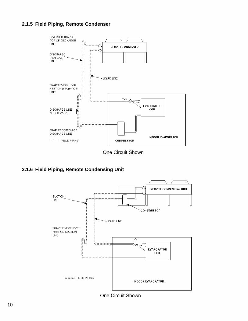
2.1.1 Discharge LinesDischarge lines, also called hot gas lines, should be trapped at the top (inverted) and bottom,
as well as every 20 feet of vertical rise. Discharge line check valves are recommended on allinstallations, especially those where there are long pipe runs or cold climate. Check valves shouldbe installed six feet from the compressor.
Discharge line pressure drop should not exceed 6 PSI. Recommended gas velocity for properoil return is 1,000 FPM. Slope horizontal lines downward in the direction of refrigerant flow 1/2" forevery ten feet of line length.
2.1.2 Liquid LinesLiquid line size is determined by pressure drop and velocity. The liquid line pressure drop
should be not exceed 5 PSI. The recommended velocity should be between 200 and 300 fpm.
To avoid excessive liquid line pressure drop, the air cooled condenser should be locatedabove or at the same level as the evaporator. Condenser installation more than ten feet below theevaporator should be avoided.
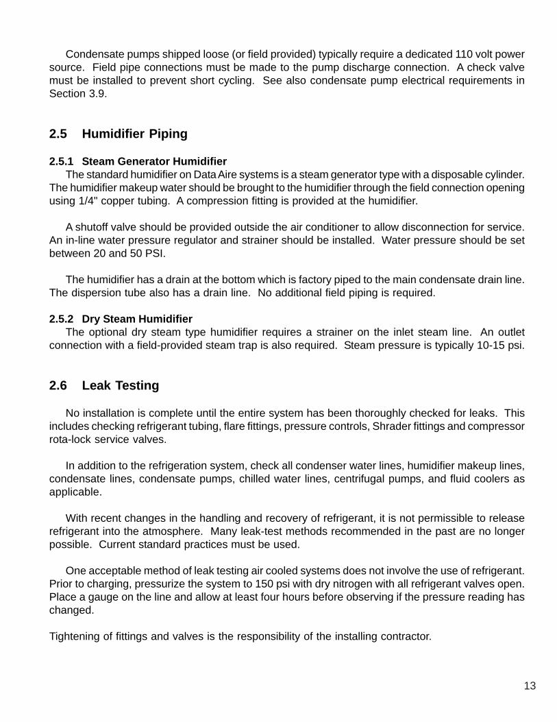
2.1.3 Suction LinesTypical floor mounted units are built with compressors in the indoor evaporator section. Some
applications call for the compressor(s) to be mounted in the outdoor condenser, or condensing unit.Such cases require field piping of liquid and suction lines. Suction lines are trapped similarly todischarge lines. Common practice for suction line selection and installation should be followed.
2.1.4 Connection Sizes, Air Cooled UnitsModel Hot Gas Liquid Model Hot Gas Liquid
DAA* 06 1/2" 1/2" DAA 16 3/4" 5/8"DAA* 08 1/2" 1/2" DAA 20 3/4" 5/8"DAA* 10 1/2" 1/2" DAA 26 3/4" 5/8"DAA* 13 1/2" 1/2" DAA 30 7/8" 5/8"
* D - downflow, U - upflow
Field connections at the indoor evaporator and remote condenser or condensing unit willnot necessarily be the same as the field pipe size required. In some cases these will varysignificantly.
10
2.1.5 Field Piping, Remote Condenser
2.1.6 Field Piping, Remote Condensing Unit
One Circuit Shown
One Circuit Shown

11
2.2 Water/Glycol Cooled Unit PipingThe required field installed condenser water pipe sizes may or may not be the same as the
connection sizes at the evaporator or fluid cooler. This will depend on the length of pipe and thecalculated pressure drop of peripheral components.
Water cooled units may also be connected to building water or tower water sources. Pipesize will depend on length of run and the maximum water flow required.
Shutoff valves should be installed within a few feet of the inlet and outlet connections of theevaporator to allow the unit to be isolated for service. A fill valve with a hose bib connection shouldalso be used on the supply line or return line at the unit to allow the unit to be drained.
DAW* 16 and DAG* 16 and larger units have a factory mounted strainer. For units withoutstrainers (13 ton and below), one should be field installed on the inlet water pipe. Strainers must becleaned periodically.
One of the most common problems in a water/glycol system is the presence of air inthe condenser water loop. Air vents must be installed in various locations in the pipingsystem to purge the air.
2.2.1 Field Piping, Glycol System

12
2.2.2 Connection Sizes, Water/Glycol Cooled Units
Evaporator Water IN and OUT Evaporator Water IN and OUTModel Connections, OD Model Connections, OD
DAW/G 06 1-5/8" DAW/G 16 2-1/8"DAW/G 08 1-5/8" DAW/G 20 2-1/8"DAW/G 10 1-5/8" DAW/G 26 2-1/8"DAW/G 13 1-5/8" DAW/G 30 2-1/8"
2.2.3 Connection Sizes, Fluid Coolers
Fluid Cooler Water IN and OUT Fluid Cooler Water IN and OUTModel Connections, OD Model Connections, OD
DAFC 06 1-5/8" DAFC 37 2-5/8"DAFC 07 1-5/8" DAFC 40 2-5/8"DAFC 09 1-5/8" DAFC 44 2-1/8"DAFC 11 2-1/8" DAFC 50 2-5/8"DAFC 15 2-1/8" DAFC 57 2-5/8"DAFC 17 2-5/8" DAFC 61 2-5/8"DAFC 21 2-1/8" DAFC 75 2-5/8"DAFC 24 2-5/8" DAFC 80 2-5/8"DAFC 28 2-5/8" DAFC 88 2-5/8"DAFC 30 2-1/8" DAFC 100 2-5/8"
Models DAFC 57 and larger are double-wide units. Although the header connection foreach section is 2-5/8", each unit comes with a factory provided manifold kit with 3-1/8"field connections.
2.3 Auxiliary Chilled Water Coil PipingUnits with an Auxiliary Chilled Water cooling coil require a separate source of chilled water.
These chilled water connection sizes will be equal to the condenser water connection sizes on thechart in Section 2.2.2. Units with an Energy Saver cooling coil have shared piping with the condensersupply and therefore do not require a separate water source.
2.4 Condensate Drain PipingEvery indoor unit has a 3/4" copper stub provided for condensate removal. A union is
recommended at the field connection which will permit easy disconnection from the unit for cleaning.
A trap should be built into the drain line to prevent air from backing up into the unit. Drainlines should be pitched downward not less than 1/4" for each ten feet of horizontal run. Do notreduce the size of the drain line.
Some applications have no convenient means of allowing a gravity drain. In this case, acondensate pump can be used. These come either factory mounted or shipped loose. Factorymounted condensate pumps do not require a separate power source.
13
Condensate pumps shipped loose (or field provided) typically require a dedicated 110 volt powersource. Field pipe connections must be made to the pump discharge connection. A check valvemust be installed to prevent short cycling. See also condensate pump electrical requirements inSection 3.9.
2.5 Humidifier Piping
2.5.1 Steam Generator HumidifierThe standard humidifier on Data Aire systems is a steam generator type with a disposable cylinder.
The humidifier makeup water should be brought to the humidifier through the field connection openingusing 1/4" copper tubing. A compression fitting is provided at the humidifier.
A shutoff valve should be provided outside the air conditioner to allow disconnection for service.An in-line water pressure regulator and strainer should be installed. Water pressure should be setbetween 20 and 50 PSI.
The humidifier has a drain at the bottom which is factory piped to the main condensate drain line.The dispersion tube also has a drain line. No additional field piping is required.
2.5.2 Dry Steam HumidifierThe optional dry steam type humidifier requires a strainer on the inlet steam line. An outlet
connection with a field-provided steam trap is also required. Steam pressure is typically 10-15 psi.
2.6 Leak Testing
No installation is complete until the entire system has been thoroughly checked for leaks. Thisincludes checking refrigerant tubing, flare fittings, pressure controls, Shrader fittings and compressorrota-lock service valves.
In addition to the refrigeration system, check all condenser water lines, humidifier makeup lines,condensate lines, condensate pumps, chilled water lines, centrifugal pumps, and fluid coolers asapplicable.
With recent changes in the handling and recovery of refrigerant, it is not permissible to releaserefrigerant into the atmosphere. Many leak-test methods recommended in the past are no longerpossible. Current standard practices must be used.
One acceptable method of leak testing air cooled systems does not involve the use of refrigerant.Prior to charging, pressurize the system to 150 psi with dry nitrogen with all refrigerant valves open.Place a gauge on the line and allow at least four hours before observing if the pressure reading haschanged.
Tightening of fittings and valves is the responsibility of the installing contractor.
14
3.0 ELECTRICAL CONNECTIONS
Before proceeding with the electrical connections, make certain that the volts, hertz,and phase correspond to that specified on the unit electrical nameplate. Use copperconductors only.
3.1 Electrical ServiceCheck to be sure the service provided by the utility is sufficient to handle the additional load
imposed by this equipment. Most units with secondary heat exchangers will require a separatepower source and field-provided, interconnecting control wires. See section 3.5 below.
Remote condensers will typically require one power source. Glycol systems with fluid coolersand loose pump(s) typically require one power source for the fluid cooler and will require one additionalsource for a single pump or two additional sources for dual pumps. Systems where the pump(s) aremounted and piped integral to the fluid cooler will usually require a single power source.
3.2 Nameplate RatingsRefer to the unit electrical nameplate for equipment electrical requirements. Minimum circuit
ampacity, (MCA) also known as wire sizing amps, will dictate the minimum required wire gauge.Maximum overcurrent protection device amps will dictate the maximum circuit breaker or fuse size.
3.3 GroundingThe unit cabinet must have an uninterrupted true earth ground. An electrical ground wire of
adequate size must be connected to the ground lug provided inside the main electrical box.
3.4 Voltage ToleranceThe supply voltage to the unit must be within 10% of the voltage indicated on the unit electrical
nameplate. Phase to phase imbalance must not exceed 3%. The local utility company should becontacted for correction of improper line voltage. Deviation from voltage ratings can cause prematurefailures and possibly void unit warranties.
3.5 Auxiliary Control WiringFor secondary heat exchangers (condensers and fluid coolers) connect two 18 gauge wires from
the electrical box of the indoor evaporator to the electrical box of the remote heat exchanger. Followthe wiring diagrams for each of these pieces of equipment. On most evaporators the terminals willbe #42 and #43. On most remote heat exchangers the terminals will be #39 and #40. All controlwiring on Data Aire equipment is 24 VAC. Condensing units (compressors mounted in condenser)typically require more wires, refer to wiring diagrams.
Check the wiring connections in the unit control panel to ensure they are tight. Screwterminals may become loose in transit. Tightening of wiring connections is theresponsibility of the installing contractor.

15
3.6 Remote ShutdownEvery Data Aire evaporator has remote shutdown contacts. These are intended for a field supplied
dry contact or switch to be wired across two terminals. When the contact or switch opens, thecontrol circuit power is interrupted and the unit shuts down, including the control panel. The controlcircuit is 24 VAC and the field provided contact or switch should have a minimum rating of 10 amps.
The remote shutdown contacts are always terminals #1 and #2 on the terminal block designatedTB1. The unit will ship with a factory wired metal jumper clip that connects terminal #1 to terminal#2. Remove this clip prior to installing the field wires.
3.7 Remote Alarm ContactsThe DAP II, microprocessor control panel provides a remote alarm output contact that can be
field accessed on terminals #11 and #12 of terminal block TB1. This is a Normally Open, Close onAlarm, dry contact, intended to be used in a control circuit not exceeding 5 amps at 24 VAC.
This programmable output contact will close on a failure and remain closed until the alarm is nolonger present. Two additional alarm output contacts come with the optional expansion module.The terminal designations for these alarm output contact pairs are #44 and #45, and #46 and #47.
3.8 Remote Sensors
Remote sensors are optional. Although existing unit mounted sensors can be removed for remotemounting, the remote sensor option provides a more convenient means of field installation. This isbecause the sensors are already connected to a predetermined length of cable and come mountedin a remote sensor enclosure. The temperature and humidity sensors require a total of six wires,these should be a twisted, shielded cable.
3.9 Condensate Pumps
Condensate pumps which ship loose normally require a separate source of 110 volt power. Alwayscheck the pump power requirements before connecting power. Condensate pumps are available inother voltages.
Condensate pumps may also come unit mounted and powered. While no outside power sourceis required, field piping is still a requirement.
Condensate pumps are wired to display a “High Condensate Water Level” alarm. The wiring forthis must be done in the field on pumps that ship loose. Factory mounted pumps come pre-wired.
3.10 Condensate ProbeA condensate probe for sensing underfloor water is included with this unit. This comes in a
plastic bag, with about 15 feet of coiled-up wire. The probe is a flat plate that is typically placedbelow the unit in a location where water is likely to accumulate.
Place the probe flat on the floor on top of a thin layer of nonconductive silicone. Secure theattached wires where necessary. A longer length of wire may be used if required.

16
Note: Failure to uncoil the length of wire attached to the condensate probe can result ina nuisance water-detected alarm. If the probe is not going to be used it should bedisconnected.
3.11 Water Sensing CableAnother option for water sensing is the Water Detection Cable. This is a long cable that can
sense moisture anywhere along its length. It is typically placed below the unit in a rectangularpattern that matches the perimeter of the unit.
17
4.0 INSTALLATION OF REMOTE HEAT EXCHANGER
Air cooled condensers and fluid coolers have individual Selection Guide/Operation andMaintenance manuals which should be referred to for more complete details.
4.1 RiggingSecondary heat exchangers matched with evaporators of this size are typically remote, outdoor
type. The heat exchanger should be moved to its (typically rooftop) mounting location using a craneor fork lift. Each fan section has heavy, steel leg supports with lifting holes at the top.
Do not lift with a choke sling around the unit. Spreader bars are recommended for lifting multiplefan units. Under no circumstances should the coil headers or piping be used for lifting the unit.Ideally, the unit should be kept in its shipping crate until it is ready to be set in place.
4.2 Leg AssemblyThe legs must be unbolted from their collapsed shipping position and extended prior to placing
the unit on its pad. Each leg extends down approximately 18" and reattaches using the same bolts.Note: Failure to extend the legs will result in poor air distribution over the cooling coil resulting insignificant capacity reduction.
Concrete pads are often used to provide support for the heat exchanger. Bolt holes in the bottomof each leg can be used to anchor the unit.
4.3 Locating the Remote Heat ExchangerRemote heat exchangers must be located in an area that will ensure free air flow into and out of
the unit plus adequate service clearance. The unit should not be placed any closer than 36" fromany wall or other obstruction.
With proper clearance on all other sides, two units can be placed side by side. Additional unitsshould be placed no closer than 48" apart.
4.4 Electrical ServiceRefer to Sections 3.1 to 3.5 for information regarding line voltage and control voltage wiring
details.
4.5 Air Cooled Condensers - Model DARC
4.5.1 Fan Speed ControlStandard outdoor air cooled condensers have a fan speed controller on the first fan at the header
end. On single-fan condensers this is the only means of control. A variable speed controller modulatesthe motor speed based on system head pressure. The fan speed controller will normally not requirefield adjustment.
4.5.2 Ambient ThermostatsAdditional motors (subsequent to the fan speed control operated motor) on multi-fan condensers
are cycled by ambient-sensing thermostats. These thermostats have a capillary tube with a remote
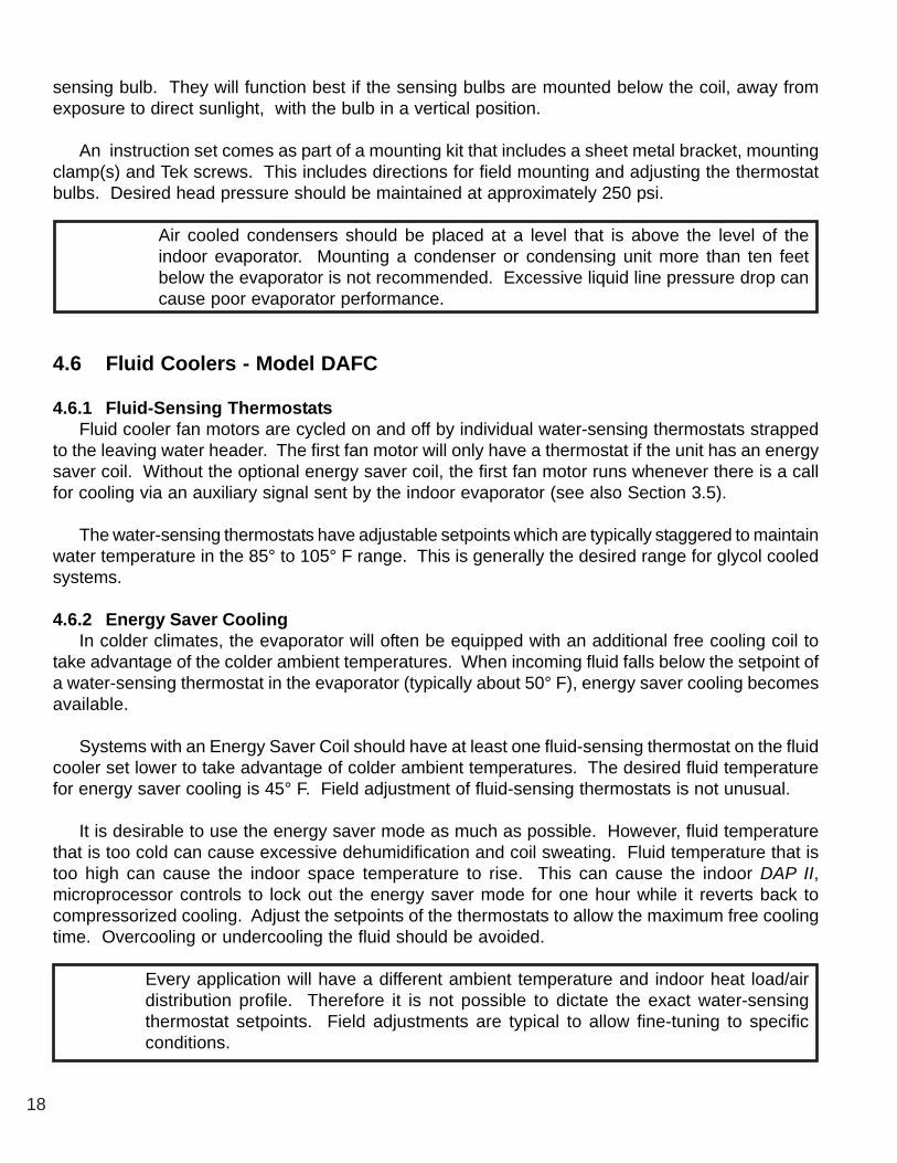
18
sensing bulb. They will function best if the sensing bulbs are mounted below the coil, away fromexposure to direct sunlight, with the bulb in a vertical position.
An instruction set comes as part of a mounting kit that includes a sheet metal bracket, mountingclamp(s) and Tek screws. This includes directions for field mounting and adjusting the thermostatbulbs. Desired head pressure should be maintained at approximately 250 psi.
Air cooled condensers should be placed at a level that is above the level of theindoor evaporator. Mounting a condenser or condensing unit more than ten feetbelow the evaporator is not recommended. Excessive liquid line pressure drop cancause poor evaporator performance.
4.6 Fluid Coolers - Model DAFC
4.6.1 Fluid-Sensing ThermostatsFluid cooler fan motors are cycled on and off by individual water-sensing thermostats strapped
to the leaving water header. The first fan motor will only have a thermostat if the unit has an energysaver coil. Without the optional energy saver coil, the first fan motor runs whenever there is a callfor cooling via an auxiliary signal sent by the indoor evaporator (see also Section 3.5).
The water-sensing thermostats have adjustable setpoints which are typically staggered to maintainwater temperature in the 85° to 105° F range. This is generally the desired range for glycol cooledsystems.
4.6.2 Energy Saver CoolingIn colder climates, the evaporator will often be equipped with an additional free cooling coil to
take advantage of the colder ambient temperatures. When incoming fluid falls below the setpoint ofa water-sensing thermostat in the evaporator (typically about 50° F), energy saver cooling becomesavailable.
Systems with an Energy Saver Coil should have at least one fluid-sensing thermostat on the fluidcooler set lower to take advantage of colder ambient temperatures. The desired fluid temperaturefor energy saver cooling is 45° F. Field adjustment of fluid-sensing thermostats is not unusual.
It is desirable to use the energy saver mode as much as possible. However, fluid temperaturethat is too cold can cause excessive dehumidification and coil sweating. Fluid temperature that istoo high can cause the indoor space temperature to rise. This can cause the indoor DAP II,microprocessor controls to lock out the energy saver mode for one hour while it reverts back tocompressorized cooling. Adjust the setpoints of the thermostats to allow the maximum free coolingtime. Overcooling or undercooling the fluid should be avoided.
Every application will have a different ambient temperature and indoor heat load/airdistribution profile. Therefore it is not possible to dictate the exact water-sensingthermostat setpoints. Field adjustments are typical to allow fine-tuning to specificconditions.
19
5.0 CHARGING
5.1 Voltage Phase Check
5.1.1 EvaporatorPrior to charging, the correct voltage phasing should be checked on the indoor evaporator. It is
easiest to check blower direction on the evaporator by momentarily moving the manual bypassswitch, located in the DAP II control panel, to the “ON” position, then back to the OFF position.Reverse any two of the three line voltage wires at the line voltage field connection point to changethe blower rotation.
Although scroll compressors are phase dependent, units shipped from the factory are run tested,ensuring the compressor rotation is consistent with the evaporator fan motor. However, a fieldchange-out of a compressor may require checking proper phase. An out-of-phase compressor willdraw relatively low amps and both suction and discharge pressures will remain nearly equal.
5.1.2 Secondary Heat ExchangerThe secondary heat exchanger may be ordered as three phase but the individual fan motors are
single phase and will only run in one direction. Check operation by placing a momentary jumperacross low voltage field terminals #39 and #40. (Disconnect pumps on glycol systems unless alreadyfilled with water/glycol solution.) This will energize the control circuit. Fans may not run because:1) the thermostat setpoint is above the current ambient, or 2) the #1 fan on air cooled condenserswith fan speed control react to head pressure. The fan will not run until the head pressure is wellover 200 psi.
5.2 Important Refrigeration Components
5.2.1 Expansion ValveEach refrigerant circuit has an adjustable thermo-expansion valve (TXV). These are factory
adjusted to their nominal rating. Any field adjustment should be to fine tune a system that hasstabilized and already has acceptable operating parameters. Adjusting a TXV to produce largeswings in superheat is not recommended.
5.2.2 High Pressure Cutout SwitchEach refrigerant circuit is protected by a high head pressure cutout switch with a manual reset
button. The cutout pressure rating for refrigerant R-22 is 400 psi. Physical location is near thecompressor, usually in the evaporator section.
5.2.3 Low Pressure Cutout SwitchEach circuit also contains a low suction pressure cutout switch with automatic reset. The cutout
pressure rating for this switch is 30 psi. Physical location is near the compressor, usually in theevaporator section.

20
5.3 Air Cooled Systems
5.3.1 Fan Speed Control System ChargingThe standard air cooled condenser for Data Aire equipment is a fan speed control system. Connect
the refrigerant drum to the low side and charge with vapor. Charge with approximately three lbs pernominal ton. For example, a model DAAU 1034 is a nominal 10 ton unit with two 5 ton circuits.Charge each circuit with about 15 lbs of refrigerant to begin. Make sure all hoses are properlypurged.
Before starting a compressor, the crankcase heaters should be energized for a minimum of 12hours to reduce the possibility of liquid slugging on start-up. Failure to energize crankcase heaterscould result in compressor damage.
An easy way to run the blower and compressor(s) is to turn the manual override switches on theDAP II, microprocessor, panel to the “ON” position. All automatic control is disabled but safetyswitches will remain functional. When charging one system at a time, it is advisable to remove thefuses of the other compressor.
Start the evaporator fan and compressor. Check the liquid line sight glass to get a feel for theapproximate charge. Bubbles in the sight glass are not unusual at this point and can be caused byflashing from liquid line pressure drop, low sub-cooling, or low charge. It is likely that more refrigerantwill be required to complete the charging procedure.
Adjust the refrigerant charge until the sight glass clears or has only sparse bubbles. Units withdual refrigerant circuits should have both compressors energized. The unit should be allowed tostabilize for several minutes before meaningful measurements can be taken.
After the system is allowed to stabilize, a few key measurements should be noted. The dischargepressure should be about 225 to 275 psi and the sub-cooling should be 8 - 10° F, depending onambient conditions. Suction temperature should be 58 psi or greater. The superheat at the compressorsuction line at least 6 inches away from the compressor should be 8-15° F.
Note: Charging to a full liquid line sight glass should never be the sole means of determining thecorrect refrigerant charge. Other parameters such as superheat, suction pressure, head pressure,sub-cooling, and ambient temperature are also important parameters. A system charged to a clearsight glass is often overcharged.

21
5.3 Air Cooled Systems
5.3.2 Flooded System ChargingFlooded systems are units having refrigerant circuits with an optional liquid receiver and head
pressure control valve. When the ambient temperature falls during cold weather, the head pressurecontrol valve will regulate the flow of refrigerant to ensure nearly constant receiver pressure. Thecondenser is partially flooded with liquid in cold weather. In warm weather the extra refrigerant isstored in the receiver.
Flooded systems require more refrigerant than fan speed control systems. While the unit isunder a vacuum, add approximately six lbs of liquid refrigerant per nominal ton directly into thereceiver. For example, a model DAAU 1034 is a nominal 10 ton unit with two 5 ton circuits. Chargeeach circuit with about 30 lbs of refrigerant to begin. Make sure all hoses are properly purged.
Before starting a compressor, the crankcase heaters should be energized for a minimumof 12 hours to reduce the possibility of liquid slugging on start-up. Failure to energizecrankcase heaters could result in compressor damage.
An easy way to run the blower and compressor(s) is to turn the manual override switches on theDAP II, microprocessor panel to the “ON” position. All automatic control is disabled but safetyswitches will remain functional. When charging one system at a time, it is advisable to remove thefuses of the other compressor.
Start the evaporator fan and compressor. Check the liquid line sight glass to get a feel for theapproximate charge. Bubbles in the sight glass are not unusual at this point and can be caused byflashing from liquid line pressure drop, low sub-cooling or low charge. It is likely that more refrigerantwill be required to complete the charging procedure.
Hook up charging gauges to the suction line. Charge with refrigerant vapor only. If the receiver(head) pressure is below 280 psi, block part of the condenser coil surface until the pressure rises to280 psi or higher. During extremely cold weather, all of the condenser fans may have to bedeenergized to maintain 280 psi.
Observe the sight glass on the receiver. Add refrigerant vapor through the suction line until thelevel of liquid in the receiver is approximately at the bottom of the sight glass which is at the 80% fulllevel. Observing the receiver sight glass becomes difficult when they are remote mounted near thecondenser.
Adjust the refrigerant charge until the sight glass clears or has only sparse bubbles. Units withdual refrigerant circuits should have both compressors energized. The unit should be allowed tostabilize for several minutes before meaningful measurements can be taken.
After the system is allowed to stabilize, the superheat at the compressor suction line at least 6inches away from the compressor should be 8-15° F. Remove the block from the condenser coil. Ifthe ambient temperature while charging is below about 60° F, some of the refrigerant will be backedup in the condenser coil, causing the liquid level in the receiver to drop.

22
Note: Charging to a full liquid line sight glass should never be the sole means ofdetermining the correct refrigerant charge. Other parameters such as superheat,suction pressure, head pressure, sub-cooling and ambient temperature are alsoimportant parameters. A system charged to a clear sight glass is often overcharged.
5.4 Water/Glycol Cooled Systems
5.4.1 Water/Glycol Cooled Systems ChargingAll water/glycol cooled units are factory charged. The water regulating valve should be adjusted
to maintain 230 to 260 psi head pressure. Suction temperature should be 58 psi or greater. Thesuperheat at the compressor suction line at least 6 inches away from the compressor should be 8-15° F.
Field charging water/glycol systems should be done by referring to the unit electrical nameplateto observe the factory charge per circuit. Although this figure represents the original factory charge,it is still necessary to measure and note proper unit operation including superheat, head, and suctionpressure. Some adjustment to charge may be required.
Adjust the refrigerant charge until the sight glass clears or has only sparse bubbles. Units withdual refrigerant circuits should have both compressors energized. The unit should be allowed tostabilize for several minutes before meaningful measurements can be taken.
All water/glycol cooled units have a water regulating valve for each refrigerant circuit. A headpressure sensing transducer is connected to a shrader fitting on the discharge line and water isregulated into the condenser coil. Condenser coils may be plate fin, coaxial, or shell and tube type.
5.4.2 Factory Charge for Water/Glycol Cooled Systems
Evaporator Factory Charge per Evaporator Factory Charge perModel Ckt, Lbs. R-22 Model Ckt, Lbs. R-22
DAW/G* 06 8 DAW/G 16 15DAW/G* 08 10 DAW/G 20 16DAW/G* 10 11 DAW/G 26 18DAW/G* 13 12 DAW/G 30 21
* D - downflow, or U - upflow
5.5 Refrigerant Handling
The use of recovery/recycling units is required by U.S. Environmental Protection Agency (EPA)regulations. Technicians who service and dispose of air conditioning and refrigeration equipmentmust recover the refrigerant instead of venting it to the atmosphere.
Except for extremely small releases of refrigerant such as what occurs when disconnecting servicehoses (diminimous release), a technician who knowingly releases or vents refrigerant to theatmosphere is in violation of this regulation. Freon purchasers must be certified technicians andhave a valid EPA certification card.

23
6.0 GLYCOL SYSTEMS
6.1 Glycol ConcentrationThe system must be filled with water and the appropriate amount of ethylene or propylene glycol
to protect against winter freeze-up. To achieve the approximate glycol concentration, it is necessaryto know the total system volume. This consists of the sum of the fluid cooler volume, the evaporatorunit volume, and the volume of the interconnecting piping.
The following tables can be used for arriving at an approximate system volume. After installation,the glycol percentage should be checked. The glycol percentage should also be checked at regularintervals to ensure freeze protection.
6.2 Internal (Fluid) Volume - Downflow Models
Evaporator Without Energy Saver Coil With Energy Saver CoilModel Volume, Gallons Volume, Gallons
DAGD 06 4.0 9.1DAGD 08 4.5 9.6DAGD 10 5.0 10.1DAGD 13 5.5 10.6DAGD 16 7.5 16.3DAGD 20 8.0 16.8DAGD 26 10.0 18.8DAGD 30 12.0 22.9
6.3 Internal (Fluid) Volume - Upflow Models
Evaporator Without Energy Saver Coil With Energy Saver CoilModel Volume, Gallons Volume, Gallons
DAGU 06 4.0 8.2DAGU 08 4.5 8.7DAGU 10 5.0 9.2DAGU 13 5.5 9.2DAGU 16 7.5 15.9DAGU 20 8.0 16.8DAGU 26 10.0 16.3DAGU 30 12.0 23.1
Note: Add 25% more for Shell and Tube condenser coils.

24
6.4 Fluid Cooler Internal Volume
Fluid Cooler Internal VolumeModel Volume, Gallons
DAFC 06 2.5DAFC 07 3.4DAFC 09 4.2DAFC 11 3.3DAFC 15 4.9DAFC 17 6.6DAFC 21 7.4DAFC 24 9.8DAFC 28 12.3DAFC 30 9.8DAFC 37 13.0DAFC 40 16.3DAFC 44 16.2DAFC 50 20.3DAFC 57 24.6DAFC 61 19.6DAFC 75 26.0DAFC 80 32.6DAFC 88 32.4DAFC 100 40.6
6.5 Copper Piping Internal Volume
Pipe Diameter Volume per 100 Feetinches of Pipe, Gallons
5/8 1.23/4 1.87/8 2.5
1-1/8 4.31-5/8 9.22-1/8 16.12-5/8 24.83-1/8 35.44-1/8 62.2
6.6 Freezing Point of Aqueous Solutions
Ethylene Glycol Freezing Point Propylene Glycol Freezing Point% by Volume Degrees F % by Volume Degrees F
0 32 0 3210 24 10 2720 15 20 1830 4 30 840 -13 40 -650 -33 50 -26

25
7.0 CONTROLS
7.1 DAP II Microprocessor Control PanelThe standard controls on all Data Aire Series equipment is the DAP II microprocessor control
panel. This state-of-the-art control panel has a separate manual that goes into extensive detailregarding functions, features, programming, and troubleshooting.
The DAP II microprocessor control panel has an entire manual dedicated to its use andoperation. This manual must be referenced to complete a thorough unit installation.Start-up is not complete until the DAP II control panel settings are established.
7.2 Secondary Heat ExchangersMost of the controls on remote condensers, condensing units, and fluid coolers consist of basic
electromechanical type components. Secondary heat exchangers have separate Selection Guide/Operation and Maintenance manuals which give complete details on adjusting thermostat settings,etc. Refer also to details in Section 3.5 within this manual.
7.3 Wiring DiagramsEvery Data Aire evaporator, condenser, condensing unit, or fluid cooler comes with a wiring
diagram. These diagrams are ‘ladder’- type schematics intended for service personnel. The intentis to allow the technician to understand the wiring details associated with the electrical componentsand how they interface with the DAP II control panel as well as peripheral equipment, includingsecondary heat exchangers.
The wiring diagram in the evaporator will indicate field interface terminals to the secondary heatexchanger. The internal wiring of the heat exchanger is found on a separate diagram which can befound on the inside cover of the heat exchanger electrical box. Both diagram types are also placedinside the shipping/warranty packet that is placed inside the evaporator.
Evaporator wiring diagrams will have a drawing number which starts out with the three letterdesignation, “DAX”. An example of a typical diagram is DAX-S-603 N. Wiring diagrams for condensersor condensing units start out with the three letter designation, “DRC”. An example of a typicaldiagram is DRC-S-001. Wiring diagrams for fluid coolers start out with the three letter designation,“DFC”. An example of a typical diagram is DFC-S-001.
26
8.0 REGULAR MAINTENANCE ITEMS
8.1 FiltersFilters should be checked on a regular basis and changed when they become dirty. This will
ensure efficient operation of the unit. Although the unit has a dirty filter alarm, this should not berelied on as the only determinant for replacing filters. A maladjusted filter differential pressureswitch may not give a proper indication of a clogged filter.
To check the filter differential pressure switch for proper adjustment, temporarily cover about75% of the return air opening using heavy cardboard or similar material. The alarm should energizewhen 75% of the air is blocked, simulating dirty filters. If the alarm energizes prematurely or doesnot energize at all, the pressure switch should be adjusted. Doors must remain closed whendetermining if an adjustment is necessary.
Spare filters should be kept in stock as these tend to be a frequently replaced maintenance item.Filters may require changing as often as monthly. Note also that construction dust on new installationswill quickly clog new filters.
Filters that require changing can restrict airflow and create problems such as coilicing or poor air distribution.
8.2 BeltsBelt tension should be checked regularly (monthly) to ensure proper tension. If tightening is
required, loosen the four motor mounting bolts. Turn the adjustment screw on the end of the motormounting channel until the proper belt tension is attained. Retighten the four mounting bolts. Damagecan also occur to belts that are overtightened. The amount of play in a typical drive set should be 1/2 inch.
8.3 BearingsPillow block bearings used on many models have zirk type grease fittings. These will only
require grease once annually. Care should be taken to avoid over-greasing. Only one or twopumps from a manual gun are required. All other blower bearings are permanently lubricated anddo not require maintenance.
Most blower motors have sealed bearings and are maintenance free. Some motors have zirktype grease fittings on the bearings. If so the motor should be greased once annually. Care shouldbe taken to avoid over-greasing. Only one or two pumps from a manual gun are required.
8.4 Humidifier CanistersSteam generator type humidifier is standard on Data Aire Series equipment. There is no
maintenance required other than to replace the canister as required. This frequency will depend onusage and water type. A set of manufacturer’s instructions for the humidifier is sent as part of thepaperwork placed inside the unit when it ships.

27
8.5 FusesFuses will occasionally require changing especially with installations where the voltage is not
consistent. Drops in voltage can create brief periods of high amp draw, causing fuses to blow.Always replace fuses with those of the equivalent rating with regard to: 1) amperage, 2) voltage,and 3) speed. For instance compressors and motors are inductive loads which require time delayfuses. Electric reheat and humidifiers are resistive loads requiring fast acting fuses.
8.6 Heating ElementsHeating elements do not normally require maintenance. However sometimes they may accumulate
a film of dust or dirt when unused for extended periods of time. When energized, the burning debriscan create smoke or unpleasant odor. To help avoid this, periodic cleaning is recommended.
8.7 Refrigerant Filter DrierFactory installed refrigerant filter driers do not normally require maintenance. When replacing
compressors or other repairs that open the refrigeration system to atmosphere, it is advisable toreplace the filter drier. The equivalent type and size should be used.

28
9.0 Warranty PolicySeller warrants its equipment to Buyer to be free from defects in material and workmanship for a
period of fifteen (15) months from date of shipment or twelve (12) months from date of start-up,whichever comes first, as long as equipment is utilized under normal conditions, serviced, and isproperly installed; however, the warranty shall not be applicable to any of the following items:refrigerant, belts, filters, humidifier, heaters not regularly cleaned, light bulbs, and any other itemseither consumed or worn out by normal wear and tear, or by conditions beyond Seller’s control,including (without limitation as to generally) polluted or contaminated air or water.
The Seller’s obligation under this warranty is limited solely to the repair or replacement, at Seller’soptions, of any part or parts thereof which shall, within fifteen (15) months from date of shipment ofthe equipment to the original purchaser be returned to the factory, transportation charges prepaid,which upon examination shall disclose to the Seller’s satisfaction to have been defective undernormal use and service. This agreement to repair or replace defective parts is expressly in lieu of allother warranties, expressed or implied and all other obligations or liabilities on the part of Seller andSeller neither assumes nor authorizes any other person to assume for it any liability of obligation inconnection with the sales or service of its equipment, except said repair or replacement of defectiveparts set forth above.
This warranty does not include any labor charges for work done outside of the factory forreplacement of parts, adjustments, repairs, or any other work. Seller’s liability does not include anyresulting damage to persons, property, equipment, goods or merchandise arising out of any defectin or failure of any equipment of its manufacture and Buyer hereby waives any claim against Sellerarising out of such claim. This warranty shall not cover the repair or replacement of any equipmentwhich has been repaired or altered outside of the factory in any way or which has been subject tonegligence, misuse, or abuse, or to pressures in excess of stated limits. On parts not manufacturedby Seller, such as motors, controls, etc., the warranty extended to Buyer shall be the same warrantyas that given to Seller by its supplier.
This warranty applies only to the original purchaser of the equipment and does not extend,expressly or by implication, to the third parties or others without the specific written approval andacknowledgment of Seller. Buyer’s exclusive remedy and Seller’s maximum liability for any and allloss, injury, damage, costs, or expense arising from any defect covered by this warranty shall belimited to the repair or replacement, but not the installation of any defective material, F.O.B., Seller’splant; provided however, that Seller shall not be required to replace any part or component (a) whichcan be repaired, or (b) unless Buyer has given Seller immediate written notice that replacement orrepair is indicated; and, provided further, however, that Seller shall not be liable for any cost orexpense of replacement or repair contracted for by Buyer with any third person, unless, and thenonly to the extent that Seller authorizes in writing, such costs or expense.
Seller shall not be liable for any direct, indirect incidental, consequential, or other loss, injury,damage cost, or expense, whether caused by delay, failure, or performance, breach of warranty, orby any cause whatsoever.
Seller’s obligation under this warranty shall be void if Buyer fails: (a) without legal justification topay Seller, when due, the full purchase price for the equipment sold hereunder; or (b) to have theequipment sold hereunder installed, maintained, and serviced by competent personnel and inaccordance with Seller’s instructions.

29
10.0 Contact Data Aire
Address:Data Aire Inc.230 W. BlueRidge AvenueOrange, CA 92865
Phone714-921-6000800-347-AIRE (2473) Toll Free
Fax:714-921-6010 Main714-921-6011 Engineering714-921-6022 Part Sales
E-mail:[email protected] Technical [email protected] [email protected] Sales
Web site:www.dataaire.com
Job information:
EvaporatorModel Number: DA__ __ - __ __ __ __ - __ __
Serial Number: __ __ __ __ - __ __ __ __ - __
Condenser/Fluid Cooler:Model Number: D __ __ __ __ __ __ __ - __ __
Serial Number: __ __ __ __ - __ __ __ __ - __
Job number: _______________________________________
Date installed: ___ / ___ / 200___
Installing Contractor: ________________________________

30
RECOMMENDED LINE SIZING FOR AIR COOLED SPLIT SYSTEMSUP TO 200 EQUIVALENT FEET
HOT GAS LINESSINGLE CIRCUIT SYSTEMS DUAL CIRCUIT SYSTEMS
Unit Tons per EQUIVALENT FEET Unit Tons per EQUIVALENT FEETTonnage Circuit 50 100 150 200 Tonnage Circuit 50 100 150 200
1 1 5/8 5/8 5/8 7/8 6 3 7/8 7/8 7/8 7/81.5 1.5 5/8 5/8 7/8 7/8 8 4 7/8 7/8 7/8 1-1/8
2 2 5/8 7/8 7/8 7/8 10 5 7/8 1-1/8 1-1/8 1-1/82.5 2.5 5/8 7/8 7/8 7/8 13 6.5 7/8 1-1/8 1-1/8 1-1/8
3 3 7/8 7/8 7/8 7/8 16 8 1-1/8 1-1/8 1-3/8 1-3/84 4 7/8 7/8 7/8 1-1/8 20 10 1-1/8 1-1/8 1-3/8 1-3/85 5 7/8 1-1/8 1-1/8 1-1/8 26 13 1-1/8 1-3/8 1-3/8 1-3/86 6 7/8 1-1/8 1-1/8 1-1/8 30 15 1-3/8 1-3/8 1-3/8 1-5/88 8 1-1/8 1-1/8 1-3/8 1-3/8
10 10 1-1/8 1-1/8 1-3/8 1-3/813 13 1-1/8 1-3/8 1-3/8 1-3/8
LIQUID LINESSINGLE CIRCUIT SYSTEMS DUAL CIRCUIT SYSTEMS
Unit Tons per EQUIVALENT FEET Unit Tons per EQUIVALENT FEETTonnage Circuit 50 100 150 200 Tonnage Circuit 50 100 150 200
1 1 3/8 3/8 3/8 3/8 6 3 1/2 1/2 1/2 1/21.5 1.5 3/8 3/8 3/8 3/8 8 4 1/2 5/8 5/8 5/8
2 2 3/8 1/2 1/2 1/2 10 5 1/2 5/8 5/8 5/82.5 2.5 3/8 1/2 1/2 1/2 13 6.5 1/2 5/8 5/8 5/8
3 3 1/2 1/2 1/2 1/2 16 8 5/8 7/8 7/8 7/84 4 1/2 5/8 5/8 5/8 20 10 5/8 7/8 7/8 7/85 5 1/2 5/8 5/8 5/8 26 13 7/8 7/8 7/8 7/86 6 1/2 5/8 5/8 5/8 30 15 7/8 7/8 7/8 7/88 8 5/8 7/8 7/8 7/8
10 10 5/8 7/8 7/8 7/813 13 7/8 7/8 7/8 7/8
SUCTION LINESSINGLE CIRCUIT SYSTEMS
Unit Tons per EQUIVALENT FEETTonnage Circuit 50 100 150 200
HOR VER HOR VER HOR VER HOR VER HOR = HORIZONTAL1 1 7/8 7/8 7/8 7/8 7/8 7/8 7/8 7/8
1.5 1.5 7/8 7/8 7/8 7/8 7/8 7/8 7/8 7/8 VERT = VERTICAL2 2 7/8 7/8 7/8 7/8 7/8 7/8 1-1/8 7/8
2.5 2.5 7/8 7/8 7/8 7/8 7/8 7/8 1-1/8 7/83 3 7/8 7/8 1-1/8 7/8 1-1/8 7/8 1-1/8 7/84 4 1-1/8 1-1/8 1-1/8 1-1/8 1-1/8 1-1/8 1-3/8 1-1/85 5 1-1/8 1-1/8 1-1/8 1-1/8 1-3/8 1-1/8 1-3/8 1-1/86 6 1-1/8 1-1/8 1-3/8 1-1/8 1-3/8 1-1/8 1-5/8 1-3/88 8 1-3/8 1-3/8 1-3/8 1-3/8 1-3/8 1-3/8 1-5/8 1-3/8
10 10 1-3/8 1-3/8 1-5/8 1-3/8 1-5/8 1-5/8 1-5/8 1-5/813 13 1-3/8 1-3/8 1-5/8 1-5/8 1-5/8 1-5/8 2-1/8 1-5/8
DUAL CIRCUIT SYSTEMSUnit Tons per EQUIVALENT FEET
Tonnage Circuit 50 100 150 200HOR VER HOR VER HOR VER HOR VER
6 3 7/8 7/8 1-1/8 7/8 1-1/8 7/8 1-1/8 7/88 4 1-1/8 1-1/8 1-1/8 1-1/8 1-1/8 1-1/8 1-3/8 1-1/8
10 5 1-1/8 1-1/8 1-1/8 1-1/8 1-3/8 1-1/8 1-3/8 1-1/813 6.5 1-1/8 1-1/8 1-3/8 1-1/8 1-3/8 1-1/8 1-5/8 1-3/816 8 1-3/8 1-3/8 1-3/8 1-3/8 1-3/8 1-3/8 1-5/8 1-3/820 10 1-3/8 1-3/8 1-5/8 1-3/8 1-5/8 1-5/8 1-5/8 1-5/826 13 1-3/8 1-3/8 1-5/8 1-5/8 1-5/8 1-5/8 2-1/8 1-5/830 15 1-5/8 1-3/8 1-5/8 1-5/8 2-1/8 1-5/8 2-1/8 1-5/8

31
Data Aire, Inc.
Monthly Maintenance Inspection Checklist
Model No. _________________ Serial No. ____________________Prepared by: _______________ Date: ___ / ___/ 200__
Air Filters___ Check for restricted air flow
Blower Section___ Blower wheel free of debris moves freely___ Check belt tension and condition___ Bearings in good condition___ Check pulleys and motor mounts
Air Distribution Section___ Check for restriction in grille(s)
Compressor___ Check oil levels (Semi-compressor only)___ Check for leaks
Refrigeration Cycle/Section___ Check crank case temperature
Air Cooled Condenser (if applicable)___ Condenser coil clean___ Motor Mounts tight___ Motor fan bearings in good condition___ Refrigeration lines properly supported
Water/Glycol Fluid Cooler (if applicable)___ Water regulating valve function___ Check for water/glycol leaks (piping area)
Glycol Pump(s)___ Glycol leaks (pump area)___ Pump operation___ Auto air vent clean of mineral deposits
Condensate Drain and Pump (if applicable)___ Check for water leaks___ Check for restricted air flow___ Pump operation
Steam Generating Humidifier___ Check canister for deposits and water level___ Check condition of steam hose and clamps
Infrared Humidifier (if applicable)___ Check humidifier lamps___ Check pan for mineral deposits
Electrical Panel___ Check contactor operation___ DAPII control panel operations
Equipment RuntimesBlower _________ hrsCondenser _________ hrsCompressor No.1 _________ hrsCompressor No. 2 _________ hrsReheat No. 1 _________ hrsReheat No. 2 _________ hrsReheat No. 3 _________ hrsHumidifier _________ hrsDehumidification _________ hrsEnergy Saver _________ hrs
__ Reset all to read zero runtimes
Temperature/Humidity set at: ___° ___% RH
Notes: ___________________________________________________________________________________________________________________________________________________________________________________________________________________________________________________________________________________________________________________________________________________________________

32
Data Aire, Inc.
Quarterly Maintenance Inspection Checklist
Model No. _______________________ Serial No. __________________________Prepared by: _____________________ Date: ___ / ___/ 200__
Air Filters____ Check for restricted air flow____ Check filter differential switch____ Wipe filter rack section clean
Blower Section____ Blower wheel free of debris and moves freely____ Check belt tension and condition____ Bearings in good condition____ Check air flow safety switch operation____ Check pulleys and motor mounts
Air Distribution Section____ Check for restriction in grille(s)
Compressor____ Check oil levels (Semi-hermetic compressor only)____ Check for leaks
Refrigeration Cycle/Section____ Check for moisture (site glass)____ Check suction pressure____ Check discharge pressure____ Check hot gas bypass valve operation____ Check thermostatic expansion valve op____ Check solenoid valve operation
Air Cooled Condenser (if applicable)____ Condenser coil clean____ Motor mounts tight____ Motor fan bearings in good condition____ Refrigeration lines properly supported____ Heated receiver site glass #1 __ #2 __
Water/Glycol Fluid Cooler (if applicable)____ Water regulating valve function____ Check solution _____%____ Check for water/glycol leaks (piping area)____ Water/Glycol flow switch operational
Glycol Pump(s)____ Glycol leaks (pump area)____ Pump operation____ Auto air vent clean of mineral deposits
Condensate Drain and Pump (if applicable)____ Check for water leaks and restricted flow____ Pump operation
Steam Generating Humidifier____ Check canister for deposits and water level____ Check condition of steam hose and clamps____ Check drain and fill valve for deposits
Infrared Humidifier (if applicable)____ Check humidifier lamps____ Check pan for mineral deposits____ Check high limit switch operation____ Check drain timer operation____ Check drain valve operation
Reheat____ Check reheat element(s) for dust____ Check high limit switch operation
Electrical Panel____ Check fuses____ Check contactor operation____ Check all electrical connections____ Check operation sequence____ Check calibration of change over thermostat
(Energy Saver System Only)DAPII control panel operations
___ Check calibration of temperature sensor (47*)___ Check calibration of humidity sensor (48*)___ Check calibration of discharge air sensor (49*)
* DAP II menu options
Equipment RuntimesBlower ____________ hrsCondenser ____________ hrsCompressor No.1 ____________ hrsCompressor No. 2 ____________ hrsReheat No. 1 ____________ hrsReheat No. 2 ____________ hrsReheat No. 3 ____________ hrsHumidifier ____________ hrsDehumidification ____________ hrsEnergy Saver ____________ hrs
___ Reset all to read zero runtimes
Temperature/Humidity set at: _____° _____% RH
Notes: __________________________________________________________________________________________________________________________________________________________________________________________________________________

33
Superheat and Suction PressureTrouble Shooting Guide
Low Suction Pressure and High Superheat1. Moisture, dirt, wax2. Undersized valve*3. High superheat adjustment4. Gas charge condensation5. Dead thermostatic element charge6. Wrong thermostatic charge7. Evaporator pressure drop - no external equalizer8. External equalizer location9. Restricted or capped external equalizer
10. Low refrigerant charge11. Liquid line vapor
a. Vertical liftb. High friction lossc. Long or small lined. Plugged drier or strainer
12. Low pressure drop across valvea. Same as #11 aboveb. Undersized distributor nozzle or circuitsc. Low condensing temperature
High Suction Pressure - Low Superheat1. Oversized valve*2. TEV seat leak3. Low superheat adjustment4. Bulb installation
a. Poor thermal contactb. Warm location
5. Wrong thermostatic charge6. Bad compressor - low capacity7. Moisture, dirt, wax8. Incorrectly located external equalizer
Low Suction Pressure - Low Superheat1. Low load
a. Not enough airb. Dirty air filtersc. Coil icing
2. Poor air distribution3. Poor refrigerant distribution4. Improper compressor-evaporator balance5. Evaporator oil logged6. Flow from one TEV affecting another’s bulb
* Data Aire has ensured that valves are size properly as the unit ships from the factory.
34
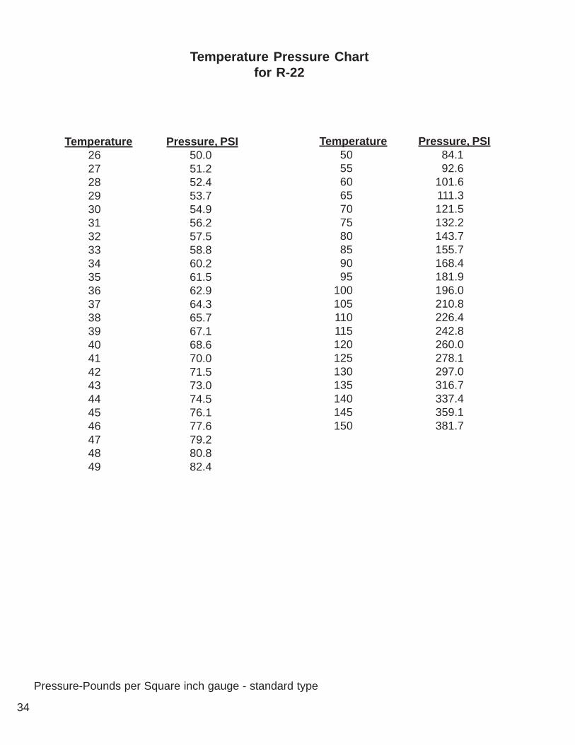
Temperature Pressure, PSI26 50.027 51.228 52.429 53.730 54.931 56.232 57.533 58.834 60.235 61.536 62.937 64.338 65.739 67.140 68.641 70.042 71.543 73.044 74.545 76.146 77.647 79.248 80.849 82.4
Temperature Pressure, PSI50 84.155 92.660 101.665 111.370 121.575 132.280 143.785 155.790 168.495 181.9
100 196.0105 210.8110 226.4115 242.8120 260.0125 278.1130 297.0135 316.7140 337.4145 359.1150 381.7
Pressure-Pounds per Square inch gauge - standard type
Temperature Pressure Chartfor R-22
35
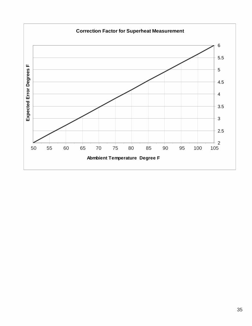
Correction Factor for Superheat Measurement
2
2.5
3
3.5
4
4.5
5
5.5
6
50 105
Abmbient Temperature Degree F
Expe
cted
Err
or D
egre
es F
50 55 60 65 70 75 80 85 90 95 100 105
36
- E -Electrical 14
Evaporator 13Energy Saver 18
Expansion Valve 19Expansion Tank 12Evaporator 6-12, 14, 20-22
- F -Fan Speed Control Systems 17, 20Field Piping 9, 30
Air Cooled 9, 10, 30Auxiliary Chilled Water 12Condensate 12Condenser 9, 10, 30Condensing Unit 10Dry Steam Humidifier 13Fluid Cooler 11Glycol Cooled 11, 23, 24Steam Generator Humidifier 13Water Cooled 11
Field Wiring 14-17, 19Remote Alarm Contacts 15Remote Condenser 14, 19Remote Condensing Unit 14Remote Fluid Cooler 14, 19Remote Sensors 15Remote Shutdown 15
FilterAir 26Drier 27Differential Pressure Switch 26
Flooded Systems 10, 21Floorstands 7Flow Switch 11Fluid Coolers 11, 12, 14, 17, 18, 22, 24Fluid Sensing Thermostats 18Freezing Point, Aqueous Solutions 24Fuses 27
- G -Glycol Concentration 23Glycol Systems
11, 12, 14, 17, 18, 22, 23, 24Grounding 14
- H -Head Pressure 20-22
Control Valve 21Cutout Switch 19Water Regulating Valve 22
- A -Air Cooled Systems 9, 10, 17-21Air Filters 26Air Vents 11Ambient Thermostats 17Auxiliary Wiring 14
- B -Bearings 26Belts 26
- C -Cable, Water Sensing 16Charging 19
Air Cooled Fan Speed Systems 20Air Cooled Flooded Systems 21Water/Glycol Systems 22
CoilsAuxiliary Chilled Water 23Condenser 23Evaporator 24\3Fluid Cooler 24Volume see Volume
CompressorsCrankcase Heaters 20, 21Manual Bypass/Override 19, 20
Condensate Cable 16Condensate Probe 16Condensate Pumps 15Condensers 10, 14, 17-21, 25Condensing Units 10,14,17-21,25Connection Sizes
Air Cooled Units 9Fluid Coolers 12Water/Glycol Cooled Units 12
Contact Data Aire 29Controls 25
DAP II Control Panel 25Secondary Heat Exchangers 25Wiring Diagrams 25
Crankcase Heaters 20, 21- D -
DAP II Control Panel 25Differential Pressure Switch 26Discharge Lines 9, 10, 30Disconnect Switch 6
INDEX

37
HeatCrankcase 20, 21Electric 27Reheat Elements 27
High Pressure Cutout Switch 19Humidifier 13, 26
Canister 26Dry Steam Humidifier 13Steam Generator Humidifier 13, 26
- I -Inspection 6Installation 6-8, 17, 18Internal Volume see Volume
- J -Jackstands 7
- L -Liquid Lines 9, 10, 30Leak Testing 13Locating 7, 17
Evaporator 7Secondary Heat Exchanger 17
- M -Maintenance 26
Bearings 26Belts 26Filters 26Fuses 26Heating Elements 27Humidifier Canisters 26Refrigerant Filter Drier 27
- P -Paperwork 8Piping See Field PipingProbe, Condensate 15, 16Pumps
Centrifugal 11Condensate 13
- R -Receivers 21Recovery 22Refrigerant 19-22
Charge see ChargingHandling 22Recovery 22
ReheatElements 27Electric 27
RemoteAlarm Contacts 15Condensers 10, 14, 17-21, 25Condensing Units 10, 14, 17-21, 25Fluid Coolers11, 12, 14, 17, 18, 22, 24Sensors 15Remote Shutdown 15
Rigging 6, 17- S -
Secondary Heat Exchange10-12, 14, 17-22, 24,25
Sight Glass 20, 21Strainer 11Subcooling 20, 21Suction Lines 9, 10, 30Superheat 20-22
- T -Thermo-expansion Valve (TXV) 19Thermostats
Ambient 17, 18Fluid Sensing 18
Traps 10- V -
ValvesHead Pressure Control 21Humidifier Makeup Water 13Shutoff 11Water Regulating 22
Voltage 14, 17, 19Phase Check 19
VolumeCopper Piping 24Fluid Coolers 24Internal Fluid, Downflow 23Internal Fluid, Upflow 23
- W -Warranty 28, 29Water Sensing Cable 16Water Sensing Probe 15, 16Wiring 14, 15, 19
- Z -Zirk Fittings 26


230 W. BlueRidge AvenueOrange, CA 92865
800-347-2473
www.dataaire.com e-mail: [email protected]
A Member of the CS Group of Companies
© 2003 Data Aire, Inc.
Data Aire, Inc. reserves the right to make design changes for the purpose of product improvement or to withdraw any design without notice.
DADXIOM-0105