Danger! - CASIO Official Websitesupport.casio.com/storage/en/manual/pdf/EN/010/DT-900_EN.pdf ·...
53
E-3 Danger! ■ Lithium-ion Battery Pack The Lithium-ion Battery Pack is available as an option. ● Never allow the battery pack to become wet. Water can create the danger of battery pack heat emission, explosion, and fire. ● Never use or leave the battery pack next to open flame, near a stove, or any other area exposed to high heat. Doing so creates the danger of battery pack heat emission, explosion, and fire. ● Never use the battery pack with any device other than this unit. Doing so can creates the danger of battery pack heat emission, explosion, and fire. ● Note that the battery pack’s positive (+) and negative (–) terminals must be oriented correctly when it is loaded into the charger unit or the Data Collector. Connecting the battery pack with its terminals reversed creates the danger of battery pack fluid leakage, heat emission, explosion, and fire. ● Never dispose of the battery pack by incinerating it or otherwise expose it to heat. Doing so creates the danger of battery pack heat emission, explosion, and fire. ● Never allow the positive (+) and negative (–) terminals of the battery pack to become connected (shorted) by metal. Doing so creates the danger of battery pack heat emission, explosion, and fire. ● Never transport or store the battery pack together with a necklace, hair pins or other metal objects. Doing so can short battery pack terminals, creating the danger of battery pack heat emission, explosion, and fire. Be sure to place the battery pack in its case whenever transporting or storing it. ● Never throw the battery pack or otherwise subject it to strong impact. Doing so creates the danger of battery pack heat emission, explosion, and fire. ● Never pierce the battery pack with nails, hit it with a hammer, or step on it. Doing so can create the danger of battery pack heat emission, explosion, and fire. ● Never try to take apart the battery pack or modify it in any way. Doing so creates the danger of battery pack heat emission, explosion, and fire. ● Use only the specified charger unit to charge the battery pack. Use of other types of charger units creates the danger of battery pack heat emission, explosion, and fire. ■ Handling Alkaline Batteries ● Should fluid from the battery pack accidentally get into your eyes, there is a threat of loss of eyesight, do not rub them. Immediately rinse your eyes with clean tap water and then consult a physician immediately.
-
Upload
duongduong -
Category
Documents
-
view
216 -
download
2
Transcript of Danger! - CASIO Official Websitesupport.casio.com/storage/en/manual/pdf/EN/010/DT-900_EN.pdf ·...

E-3
Danger!■ Lithium-ion Battery Pack
The Lithium-ion Battery Pack is available as an option.● Never allow the battery pack to become wet. Water can create the danger of
battery pack heat emission, explosion, and fire.● Never use or leave the battery pack next to open flame, near a stove, or any
other area exposed to high heat. Doing so creates the danger of batterypack heat emission, explosion, and fire.
● Never use the battery pack with any device other than this unit. Doing so cancreates the danger of battery pack heat emission, explosion, and fire.
● Note that the battery pack’s positive (+) and negative (–) terminals must beoriented correctly when it is loaded into the charger unit or the DataCollector. Connecting the battery pack with its terminals reversed creates thedanger of battery pack fluid leakage, heat emission, explosion, and fire.
● Never dispose of the battery pack by incinerating it or otherwise expose it toheat. Doing so creates the danger of battery pack heat emission, explosion,and fire.
● Never allow the positive (+) and negative (–) terminals of the battery pack tobecome connected (shorted) by metal. Doing so creates the danger ofbattery pack heat emission, explosion, and fire.
● Never transport or store the battery pack together with a necklace, hair pinsor other metal objects. Doing so can short battery pack terminals, creatingthe danger of battery pack heat emission, explosion, and fire. Be sure toplace the battery pack in its case whenever transporting or storing it.
● Never throw the battery pack or otherwise subject it to strong impact. Doingso creates the danger of battery pack heat emission, explosion, and fire.
● Never pierce the battery pack with nails, hit it with a hammer, or step on it.Doing so can create the danger of battery pack heat emission, explosion,and fire.
● Never try to take apart the battery pack or modify it in any way. Doing socreates the danger of battery pack heat emission, explosion, and fire.
● Use only the specified charger unit to charge the battery pack. Use of othertypes of charger units creates the danger of battery pack heat emission,explosion, and fire.
■ Handling Alkaline Batteries● Should fluid from the battery pack accidentally get into your eyes, there is a
threat of loss of eyesight, do not rub them. Immediately rinse your eyes withclean tap water and then consult a physician immediately.
E-4
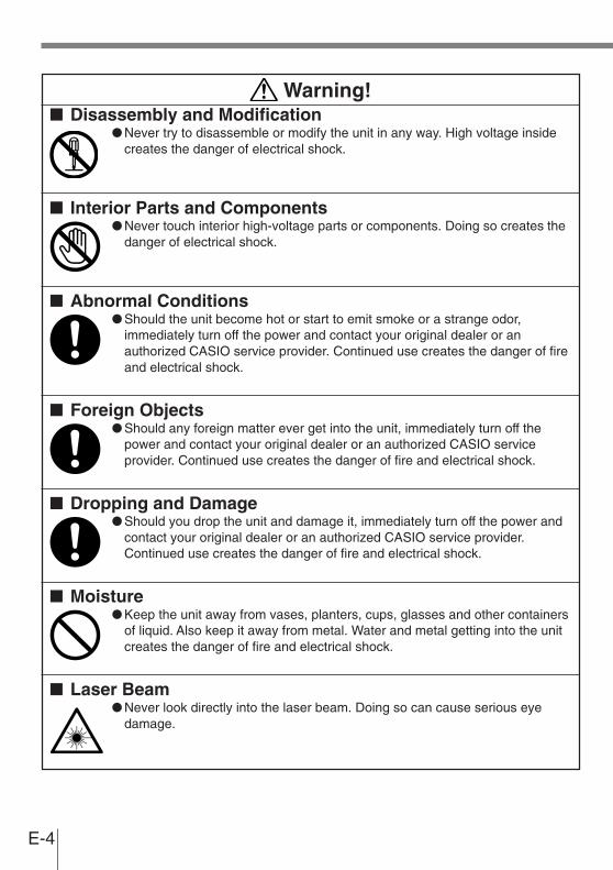
Warning!■ Disassembly and Modification
● Never try to disassemble or modify the unit in any way. High voltage insidecreates the danger of electrical shock.
■ Interior Parts and Components● Never touch interior high-voltage parts or components. Doing so creates the
danger of electrical shock.
■ Abnormal Conditions● Should the unit become hot or start to emit smoke or a strange odor,
immediately turn off the power and contact your original dealer or anauthorized CASIO service provider. Continued use creates the danger of fireand electrical shock.
■ Foreign Objects● Should any foreign matter ever get into the unit, immediately turn off the
power and contact your original dealer or an authorized CASIO serviceprovider. Continued use creates the danger of fire and electrical shock.
■ Dropping and Damage● Should you drop the unit and damage it, immediately turn off the power and
contact your original dealer or an authorized CASIO service provider.Continued use creates the danger of fire and electrical shock.
■ Moisture● Keep the unit away from vases, planters, cups, glasses and other containers
of liquid. Also keep it away from metal. Water and metal getting into the unitcreates the danger of fire and electrical shock.
■ Laser Beam● Never look directly into the laser beam. Doing so can cause serious eye
damage.
E-5
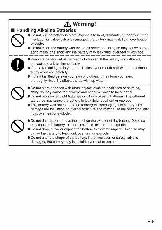
Warning!■ Handling Alkaline Batteries
● Do not put the battery in a fire, expose it to heat, dismantle or modify it. If theinsulation or safety valve is damaged, the battery may leak fluid, overheat orexplode.
● Do not insert the battery with the poles reversed. Doing so may cause someabnormality or a short and the battery may leak fluid, overheat or explode.
● Keep the battery out of the reach of children. If the battery is swallowed,contact a physician immediately.
● If the alkali fluid gets in your mouth, rinse your mouth with water and contacta physician immediately.
● If the alkali fluid gets on your skin or clothes, it may burn your skin,thoroughly rinse the affected area with tap water.
● Do not store batteries with metal objects such as necklaces or hairpins,doing so may cause the positive and negative poles to be shorted.
● Do not mix new and old batteries or other makes of batteries. The differentattributes may cause the battery to leak fluid, overheat or explode.
● This battery was not made to be recharged. Recharging this battery maydamage the insulation or internal structure and may cause the battery to leakfluid, overheat or explode.
● Do not damage or remove the label on the exterior of the battery. Doing somay cause the battery to short, leak fluid, overheat or explode.
● Do not drop, throw or expose the battery to extreme impact. Doing so maycause the battery to leak fluid, overheat or explode.
● Do not alter the shape of the battery. If the insulation or safety valve isdamaged, the battery may leak fluid, overheat or explode.

E-6
Warning!■ Handling the Coin Type Lithium Battery
● Do not recharge coin type lithium battery. Doing so may cause it to leak fluid,overheat, explode or burst into flames.
● Do not put the coin type lithium battery in open flame, or apply solder directlyto the coin type lithium battery. Doing so may cause it to leak fluid, overheat,explode or burst into flames.
● Do not use the coin type lithium battery with the positive and negative polesreversed. Do not store it with metal objects such as necklaces or hairpins,doing so may cause the positive and negative poles to be shorted.
● Keep the coin type lithium battery out of the reach of children. If it isswallowed, contact a physician immediately.
● If the alkali fluid gets in your eye, rinse the eye with water and contact aphysician immediately.
● If the alkali fluid gets in your mouth, rinse your mouth with water and contacta physician immediately.
● If the coin type lithium battery leaks fluid or emits a strange smell,immediately remove it from near heat or flames. Burning may cause it toexplode or burst into flames.
● When storing or disposing of the coin type lithium battery, cover theterminals with tape to insulate them. Mixing them with other batteries ormetal objects may cause the coin type lithium battery to short, leak fluid,overheat, explode or burst into flames.
■ Lithium-ion Battery Pack● Do not put a battery pack in microwave ovens or pressure cookers. Doing so
may cause the battery pack to overheat, explode or burst into flames.● Do not use a battery pack that smells strange, is overheating, is a strange
color, or is a strange shape. Doing so may cause the battery pack tooverheat, explode or burst into flames.
● If the amount of time period the battery pack can serve becomesconsiderably short, stop using it. It may indicate the possibility of amalfunction in the battery pack. Continued charging the battery pack createsthe danger of heat emission, explosion, and fire.
● Stop charging the battery pack after the recommended time even if it is notfully charged. Continuing to charge the battery may cause the battery packto overheat, explode or burst into flames.
● If the battery pack leaks fluid or emits a strange smell, remove it from nearheat or flames. Burning may cause the battery pack to explode or burst intoflames.
● Should fluid from the battery pack accidentally get into your eyes, do not rubthem. Immediately rinse your eyes with clean water such as tap water andthen consult a physician immediately.
E-7
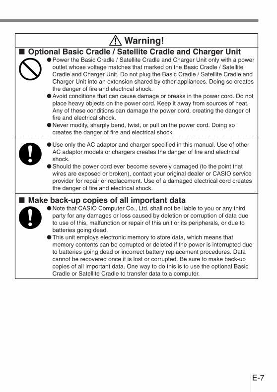
Warning!■ Optional Basic Cradle / Satellite Cradle and Charger Unit
● Power the Basic Cradle / Satellite Cradle and Charger Unit only with a poweroutlet whose voltage matches that marked on the Basic Cradle / SatelliteCradle and Charger Unit. Do not plug the Basic Cradle / Satellite Cradle andCharger Unit into an extension shared by other appliances. Doing so createsthe danger of fire and electrical shock.
● Avoid conditions that can cause damage or breaks in the power cord. Do notplace heavy objects on the power cord. Keep it away from sources of heat.Any of these conditions can damage the power cord, creating the danger offire and electrical shock.
● Never modify, sharply bend, twist, or pull on the power cord. Doing socreates the danger of fire and electrical shock.
● Use only the AC adaptor and charger specified in this manual. Use of otherAC adaptor models or chargers creates the danger of fire and electricalshock.
● Should the power cord ever become severely damaged (to the point thatwires are exposed or broken), contact your original dealer or CASIO serviceprovider for repair or replacement. Use of a damaged electrical cord createsthe danger of fire and electrical shock.
■ Make back-up copies of all important data● Note that CASIO Computer Co., Ltd. shall not be liable to you or any third
party for any damages or loss caused by deletion or corruption of data dueto use of this, malfunction or repair of this unit or its peripherals, or due tobatteries going dead.
● This unit employs electronic memory to store data, which means thatmemory contents can be corrupted or deleted if the power is interrupted dueto batteries going dead or incorrect battery replacement procedures. Datacannot be recovered once it is lost or corrupted. Be sure to make back-upcopies of all important data. One way to do this is to use the optional BasicCradle or Satellite Cradle to transfer data to a computer.
E-8
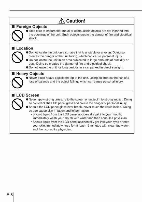
Caution!■ Foreign Objects
● Take care to ensure that metal or combustible objects are not inserted intothe openings of the unit. Such objects create the danger of fire and electricalshock.
■ Location● Do not locate the unit on a surface that is unstable or uneven. Doing so
creates the danger of the unit falling, which can cause personal injury.● Do not locate the unit in an area subjected to large amounts of humidity or
dust. Doing so creates the danger of fire and electrical shock.● Do not leave the unit for long periods in a car parked in direct sunlight.
■ Heavy Objects● Never place heavy objects on top of the unit. Doing so creates the risk of a
loss of balance and the object falling, which can cause personal injury.
■ LCD Screen● Never apply strong pressure to the screen or subject it to strong impact. Doing
so can crack the LCD panel glass and create the danger of personal injury.● Should the LCD panel glass ever break, never touch the liquid inside. Doing
so can cause skin irritation and inflammation.• Should liquid from the LCD panel accidentally get into your mouth,
immediately wash your mouth with water and then consult a physician.• Should liquid from the LCD panel accidentally get into your eyes or onto
your skin, immediately rinse for at least 15 minutes with clean tap waterand then consult a physician.

E-9
Caution!■ Handling Alkaline Batteries
● Store batteries someplace out of direct sunlight where the temperature andhumidity are not high. Not doing so may cause the batteries to leak fluid,overheat or explode. Also, it may cause the life and performance of thebatteries to decline.
● These batteries can be disposed of as regular garbage, however, ifapplicable, follow the regulations of the local government when disposing ofthese batteries.
● Immediately remove batteries when they have lost all power. Leaving thebatteries in the unit for a long time may cause the batteries to leak fluid,overheat or explode due to gas that is generated by the batteries.
● Remove the batteries from the unit when not using the unit for an extendedperiod of time. The batteries may leak fluid, overheat or explode due to gasthat is generated by the batteries.
● Do not apply solder directly to the batteries. The heat may cause thebatteries to leak fluid, overheat or explode.
● Do not store the batteries in the direct sunlight or in a car on a sunny daywhen it is very hot. The batteries may leak fluid, overheat or explode.
● When storing or disposing of the batteries, cover the terminals with tape toinsulate them. Mixing them with other batteries or metal objects may causethe batteries to leak fluid, overheat or explode.
● Do not get the batteries wet. Doing so may cause the batteries to overheat.
■ Handling the Coin Type Lithium Battery● Do not drop, expose to severe impact or alter the shape of the coin type
lithium battery. Also, do not get the battery wet. Doing so may cause it toleak fluid, overheat or explode.
● Do not store the coin type lithium battery in the direct sunlight or in a car on asunny day when it is very hot. It may leak fluid, overheat or explode.
● Store the coin type lithium battery someplace out of direct sunlight where thetemperature and humidity are not high. Not doing so may cause it to leakfluid, overheat or explode. Also, it may cause the life and performance of thebattery to decline.
● The coin type lithium battery can be disposed of as regular garbage,however, if applicable, follow the regulations of the local government whendisposing it.

E-10
Caution!■ Lithium-ion Battery Pack
The Lithium-ion Battery Pack is available as an option.● Never leave the battery pack in an area expose to direct sunlight, in a car
parked in direct sunlight, or any other very hot area. Doing so creates thedanger of heat emission and fire, as well as deterioration of battery packperformance and shortening of its service life.
● Do not use the battery pack in areas where static electricity is beinggenerated. Doing so creates the danger of battery pack heat emission,explosion, and fire.
● Temperature ranges for battery pack use, charging, and storage arespecified below. Temperatures outside these ranges create the danger ofdeterioration of battery pack performance and shortening of its service life,as well as fluid leakage and heat generation.
Operating Temperature: –5°C to 50°CCharging Temperature: 0°C to 40°CStorage Temperature: –20°C to 60°C
● Should fluid from the battery pack accidentally get onto clothing or your skin,immediately rinse it off with clean tap water. Prolonged contact with batterypack fluid can cause skin irritation.
● Keep the battery pack out of the reach of small children. Do not let smallchildren remove the battery pack from the charger unit or the unit it ispowering.
■ Optional Basic Cradle / Satellite Cradle and Charger Unit● Keep the power cord away from stoves and other sources of extreme heat.
Heat can melt the insulation of the power cord and create the danger of fireand electrical shock.
● Never pull on the power cord when unplugging it. Doing so can damage thecord and create the danger of personal injury, fire and electrical shock.Always hold onto the plug when unplugging it from the wall outlet.
● Never touch the plug while your hands are wet. Doing so can create thedanger of electrical shock.
● Be sure to unplug the power cord from the wall outlet before moving theBasic Cradle / Satellite Cradle and Charger Unit. Failure to do so can resultin damage to the power cord caused by pulling it, which creates the dangerof fire and electrical shock.
● Be sure to unplug the power cord from the wall outlet before cleaning theBasic Cradle / Satellite Cradle and Charger Unit.
● Be sure to turn the power OFF and unplug the power cord after use.● Unplug the power cord from the wall outlet and clean the area around the
plugs at least once a year. If dust collects on the AC adaptor, humidity ormoisture may cause a fault in the insulation, which may result in a fire.

E-11
IntroductionMake sure you carefully read the following information to ensure that your Data Collector isable to perform at the level for which it is designed.
Handling Precautions
• Do not throw or drop the Data Collector or otherwise subject it to strong impact, which candamage the LCD screen, interrupt program execution, corrupt memory contents, orotherwise interfere with proper operation.
• Use only your finger or a blunt object to operate the stroke keys. Use of a sharp pointedobject can damage stroke keys and cause shorting of internal circuitry.
• Use a soft, dry cloth when cleaning the Data Collector. Do not wipe with a wet cloth. Donot use benzine, thinner, or other volatile chemicals, which can result in deformation anddeterioration of the materials used in the keys and case.
• Do not lay the Data Collector down with its key panel downwards. Doing so runs the riskof accidental key operation, which can cause malfunction.
• Never remove the main battery while Data Collector power is turned ON. Doing so cancause all data in memory to be lost.
• Sudden temperature changes can cause condensation to form on the Data Collector’scase. Operating the Data Collector while condensation is present can interfere with properoperation. Take care to avoid conditions that cause the formation of condensation. Ifcondensation does form, wait until it dries completely before using the Data Collector.

E-12
• The contents of this manual are subject to change without notice.• The term “Data Collector” as used in this User’s Guide refers to the CASIO DT-900 Data
Collector unless otherwise noted.• CASIO COMPUTER CO., LTD. assumes no responsibility for any loss or claims by third
parties which may arise from the use of this manual.• This manual does not cover programming and the uploading of data. See the separate
manuals for details of these procedures.
ContentsSafety Precautions ............................................... E-2
Introduction ......................................................... E-11Handling Precautions ........................................................... E-11
Unpacking ........................................................... E-14
DT-900 System Diagram ..................................... E-15
General Guide ..................................................... E-16
Power Supply ...................................................... E-17Loading and Removing the AA (LR6)-size alkaline batteries ... E-18Loading and Removing the Lithium-ion Battery Pack .......... E-19Replacing the Lithium Backup Battery ................................. E-20
About the LCD Screen........................................ E-22
Attaching the Wrist Strap ................................... E-23To attach the wrist strap ....................................................... E-23
Keys and Their Functions .................................. E-24
Using the Bar Code Reader ............................... E-25Performing a Bar Code Read Operation.............................. E-25Performing a Bar Code ........................................................ E-26Adjusting the Laser Beam Width ......................................... E-27
Data Communication .......................................... E-29DT-900 - DT-900 Data Communication ............................... E-29
Specifications ..................................................... E-30Lithium-Ion Battery Pack (DT-923LI) ................................... E-31
Using the Basic Cradle....................................... E-32General Guide ..................................................................... E-32When You Are Using the Down-facing Reader Port Model .. E-34Setting up the Basic Cradle and
connecting the Data Collector ......................................... E-34Serial Connection of Multiple Basic Cradles ........................ E-36DIP Switch Settings ............................................................. E-36DT-960IOE Basic Cradle Specifications .............................. E-37
E-13
Using the Satellite Cradle .................................. E-38General Guide ..................................................................... E-38When You Are Using the Down-facing Reader Port Model .. E-40Setting up the Satellite Cradle and
Connecting the Data Collector ........................................ E-40Charging the Battery Pack ................................................... E-42Charging the Battery Pack
(charging the lithium-ion battery pack separately) .......... E-43Serial Connection of Multiple Satellite Cradles .................... E-44DIP Switch Settings ............................................................. E-45DT-964IOE Satellite Cradle Specifications .......................... E-46
Using the Chager Unit ........................................ E-47General Guide ..................................................................... E-47When You Are Using the Down-facing Reader Port Model .. E-49Setting up the Charger Unit
and Connecting the Data Collector ................................. E-49Charging the Battery Pack
(charging the lithium-ion battery pack separately) .......... E-51DT-969CHGE Charger Unit Specifications .......................... E-52
Setting the Unit ................................................... E-53To use the Basic Cradle / Satellite Cradle on a desktop
(example: Satellite Cradle) .............................................. E-53To hang the Basic Cradle / Satellite Cradle on a wall
(example: Satellite Cradle) .............................................. E-53
CASIO Europe GmbHBornbarch 10, D-22848Norderstedt, Germany
This mark applies in EU countries only.

E-14
UnpackingWhen unpacking the Data Collector, check carefully that all of the items shown below areincluded. If anything is missing or damaged, contact your original dealer or your nearestCASIO Service Provider.
• Data Collector(down-facing reader port) (forward-facing reader port)
DT-900 M50E/M60E DT-900 M51E/M61E
• Wrist Strap
• Back-up battery (lithium)
• Main battery (Two AA (LR6)-size alkaline batteries)
E-15
0 ENT
L R7 8 9
F2F1 F3 F4
F5 F6 F7 F8
4 5 6
1 2
•
3
0 ENT
L R7 8 9
F2F1 F3 F4
F5 F6 F7 F8
4 5 6
1 2
•
3
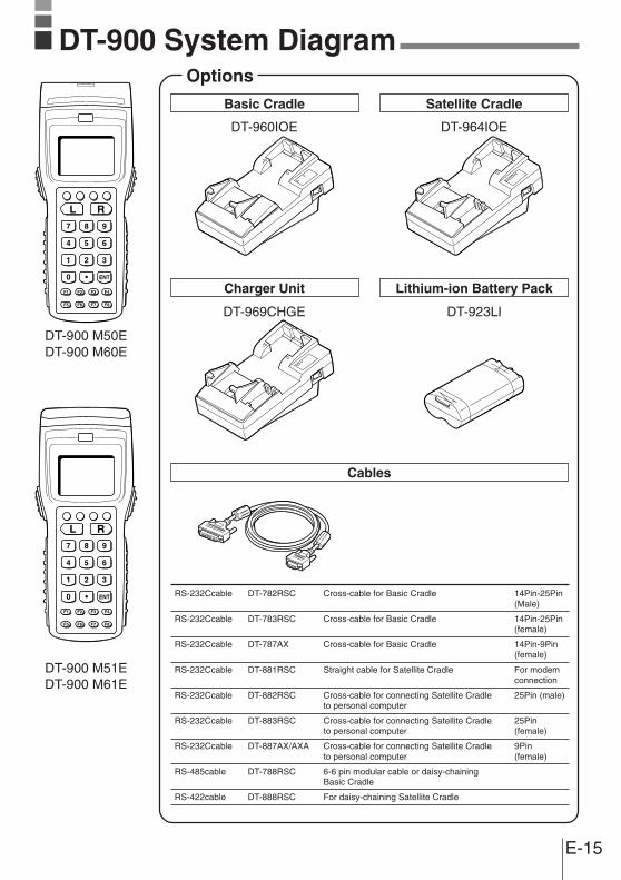
DT-900 System DiagramOptions
Basic Cradle
DT-960IOE
Charger Unit
DT-969CHGE
Satellite Cradle
DT-964IOE
Lithium-ion Battery Pack
DT-923LI
DT-900 M50EDT-900 M60E
DT-900 M51EDT-900 M61E
Cables
RS-232Ccable DT-782RSC Cross-cable for Basic Cradle 14Pin-25Pin(Male)
RS-232Ccable DT-783RSC Cross-cable for Basic Cradle 14Pin-25Pin(female)
RS-232Ccable DT-787AX Cross-cable for Basic Cradle 14Pin-9Pin(female)
RS-232Ccable DT-881RSC Straight cable for Satellite Cradle For modemconnection
RS-232Ccable DT-882RSC Cross-cable for connecting Satellite Cradle 25Pin (male)to personal computer
RS-232Ccable DT-883RSC Cross-cable for connecting Satellite Cradle 25Pinto personal computer (female)
RS-232Ccable DT-887AX/AXA Cross-cable for connecting Satellite Cradle 9Pinto personal computer (female)
RS-485cable DT-788RSC 6-6 pin modular cable or daisy-chainingBasic Cradle
RS-422cable DT-888RSC For daisy-chaining Satellite Cradle
E-16
0 ENT
L R7 8 9
F2F1 F3 F4
F5 F6 F7 F8
4 5 6
1 2
•
3
4
8
8
3
1
2
4
57
13
6
1
10
9
11
12
14
15
DEL
SP BL
S BS CLR PW
$/+
YZ-VWXSTU
PQRMNOJKL
GHIDEFABC
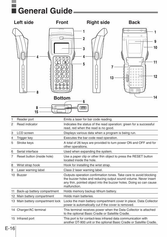
General Guide
1 Reader port Emits a laser for bar code reading.
2 Read indicator Indicates the status of the read operation: green for a successfulread, red when the read is no good.
3 LCD screen Displays various data when a program is being run.
4 Trigger key Executes the bar code read operation.
5 Stroke keys A total of 26 keys are provided to turn power ON and OFF and forother operations.
6 Serial interface Used when expanding the system.
7 Reset button (inside hole) Use a paper clip or other thin object to press the RESET buttonlocated inside the hole.
8 Wrist strap hook Hook for installing the wrist strap.
9 Laser warning label Class 2 laser warning label.
10 Buzzer Outputs operation confirmation tones. Take care to avoid blockingthe buzzer holes and reducing output sound volume. Never insertany thin, pointed object into the buzzer holes. Doing so can causemalfunction.
11 Back-up battery compartment Holds memory backup lithium battery.
12 Main battery compartment Holds main batteries.
13 Main battery compartment lock Locks the main battery compartment cover in place. Data Collectorpower is automatically cut if the cover is removed.
14 Charger/AC terminal This terminal receives power when the Data Collector is attachedto the optional Basic Cradle or Satellite Cradle.
15 Infrared port This port is for contact-less infrared data communication withanother DT-900 unit or the optional Basic Cradle or Satellite Cradle.
Left side Front Right side Back
Bottom

E-17
Power SupplyThe Data Collector has both a main power supply (two AA (LR6)-size alkaline
batteries or a lithium-ion battery pack) and a backup power supply (lithium battery).
In this manual, the words "main battery" refer to both alkaline batteries and the
lithium-ion battery pack.Low main battery power is indicated when the low voltage message appears on the LCDscreen. Replace the main battery or charge the battery pack as soon as possible after thelow voltage message appears.
[Warning]■ Note Down Valuable Data
• Never remove both the main battery and backup battery at the sametime. Doing so causes all program settings and data in Data Collectormemory to be lost or changed. Data cannot be recovered once it is lostor corrupted. Be sure to make back-up copies of all important data.One way to do this is to use the optional Basic Cradle or SatelliteCradle to transfer data to a computer.
Important! • Never remove the main battery from the Data Collector while the poweris turned ON. Doing so can cause data in Data Collector memory to belost. Before you remove the battery, be sure to turn the Data CollectorOFF.
• Use only AA (LR6)-size alkaline batteries or the specified lithium-ionbattery pack specified for the DT-900.
• The lithium-ion battery pack discharges naturally during the time ittakes to get to you from the factory. Be sure to charge the battery packbefore you use it for the first time.
• Never allow the terminals of the lithium-ion battery to become shorted.Doing so creates the danger of malfunction. Be sure to keep thebattery pack in its special case when transporting or storing it.
• Repeat charging of the lithium-ion battery pack gradually shortens itsability to recharge. If you find that a fully charged battery packprovides only little operation time, it probably means you need a newbattery pack.
• Whenever you do not plan to use the Data Collector for a long time,load two new alkaline batteries or a fully charged battery pack into theData Collector to protect against power failure during non-use. Also,load new batteries or a fully charged battery pack before using theData Collector after a long period of non-use.
• If the battery pack has been left over unused for a long period of time,the capacity remained decreases due to spontaneous discharge orchemical decomposition by the battery pack itself. If the battery packfails to hold its operating duration after it has been fully charged,replace it with a new one. The battery pack may reach the end of itsservice life.

E-18
Power Supply
Loading and Removing the AA (LR6)-size alkaline batteries
Important! When you load the AA (LR6)-size alkaline batteries, make sure thattheir positive (+) and negative (–) ends are facing the correctdirections.
Loading the Main Battery
1 Slide the main battery compartment coverlock to the FREE position and remove thecover.If the main battery compartment cover doesnot open, lift up tab “a” with your fingernail ora thin object.
2 Load two new AA (LR6)-size alkaline batteriesinto the main battery compartment, makingsure that they face the directions shown in thefigure.
3 Attach the battery compartment cover to theData Collector and slide the main batterycompartment cover lock to the LOCK position.
Removing the Main Battery
Remove main batteries following the loading procedure in reverse.Be sure to turn the Data Collector OFF before you do this.
a
E-19
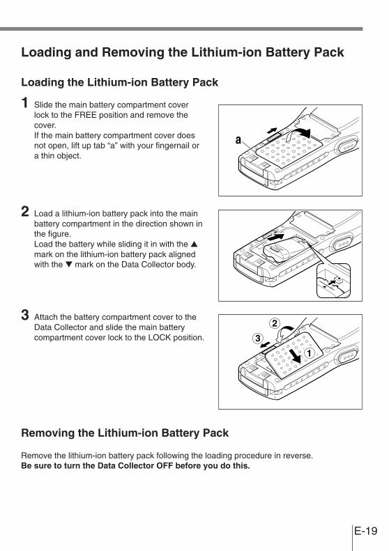
Loading and Removing the Lithium-ion Battery Pack
Loading the Lithium-ion Battery Pack
1 Slide the main battery compartment coverlock to the FREE position and remove thecover.If the main battery compartment cover doesnot open, lift up tab “a” with your fingernail ora thin object.
2 Load a lithium-ion battery pack into the mainbattery compartment in the direction shown inthe figure.Load the battery while sliding it in with the ▲mark on the lithium-ion battery pack alignedwith the ▼ mark on the Data Collector body.
3 Attach the battery compartment cover to theData Collector and slide the main batterycompartment cover lock to the LOCK position.
Removing the Lithium-ion Battery Pack
Remove the lithium-ion battery pack following the loading procedure in reverse.Be sure to turn the Data Collector OFF before you do this.
a

E-20
Power Supply
Replacing the Lithium Backup Battery
When the lithium backup battery low voltage message appears on the LCD screen,immediately replace the backup battery (lithium). Use a CR2032 lithium battery as thereplacement battery. Be sure to turn the Data Collector OFF before you do this.
[Warning]■ Note Down Valuable Data
• When you remove the backup battery with the main battery removed orin a low-power state, data may be lost or may change. Data cannot berecovered once it is lost or corrupted. Be sure to make back-up copiesof all important data. One way to do this is to use the optional BasicCradle or Satellite Cradle to transfer data to a computer.
Important! • Make sure that the positive (+) and negative (–) ends of the battery arefacing the correct directions.
1 Use a screwdriver to rotate the screw thatsecures the backup battery holder in placecounterclockwise to loosen it.
2 Open the backup battery compartment cover.
E-21
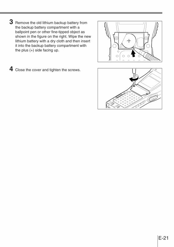
3 Remove the old lithium backup battery fromthe backup battery compartment with aballpoint pen or other fine-tipped object asshown in the figure on the right. Wipe the newlithium battery with a dry cloth and then insertit into the backup battery compartment withthe plus (+) side facing up.
4 Close the cover and tighten the screws.

E-22
About the LCD ScreenThe LCD screen of the Data Collector shows program settings, operational procedures,calculation results and other information.
• Display Area64 dots (V) x 128 dots (H)
• Display Characters12-dot, 16-dot and 20-dot modesEach mode allows mixing of the following three fonts:
• Character TypesAlpha-characters, numbers, symbols
• Text EffectsBolding, highlighting, and other effects can be used with alpha-characters, numbers, andsymbols.
Built-in ClockThe DT-900 has a built-in clock, so programs can be written to perform operations at certaintimes.
• Example Display
2002 / 11 / 11
Year Month Day
14 : 25
Hour Minute
12-dot Mode 16-dot Mode 20-dot Mode
AN 21 columns x 10 lines 16 columns x 8 lines 12 columns x 6 lines
Half-size 21 columns x 5 lines 16 columns x 4 lines 12 columns x 3 lines

E-23
The wrist strap protects the Data Collector from being damaged as a result of it beingdropped by mistake during movement.Follow the procedure below to attach the wrist strap.
To attach the wrist strap
1 Pass the thin end of the wrist strap throughthe metal hand strap mount on the bottomside of the Data Collector.
2 Double the strap back through its own loop,and pull it tight.
Important! • Never swing the Data Collector around by its wrist strap.
Attaching the Wrist Strap

E-24
123
15
4
6
7
Keys and Their FunctionsOperations are controlled by trigger keys and stroke keys.
1 Trigger keysTrigger a bar code read operation.
2 Control keysCLR key: Cancels input.BS key: Backspaces and deletes one
character.S key: Switches between the character
input mode and the number inputmode.
lit on the LCD screen indicatesthe character input mode. When is not lit, the Data Collector is in thenumber input mode.
3 Multi-function (L/R) keysKeys that can be assigned any function.
4 10-key padThe function of these keys depends on whetherthe Data Collector is in the character input modeor the number input mode.Character input mode: Input alpha-characters
and symbols.Number input mode: Inputs the numbers 0 to 9
and the decimal point.5 Power key Turns power ON and OFF.
6 Enter key Registers input.
7 Function keysKeys that can be assigned any function except forthe trigger key function. The following are theinitial functions assigned to these keys.F1 (–): Inputs the minus (–) sign.F2 (←): Moves the cursor left.F3 (→): Moves the cursor right.F4 (DEL): Deletes a character.F5 (SP): Inputs a space.F6 (▲): Increases display contrast.F7 (▼): Decreases display contrast.F8 (BL): Turns the display backlight ON and OFF.

E-25
Performing a Bar Code Read Operation
1 Press the [PW] key to turn power on. Hold theData Collector close to the bar code andpress the trigger key.
2 The reader port emits a laser to read the barcode. The read indicator lights green whenthe read is successful.
Important! • If you have problems with the read operation, change the angle betweenthe label and Data Collector, or move closer and then try again.
• If the bar code is larger than the diameter of the Data Collector’s readerport, try moving the Data Collector a bit farther away from the bar code.
• The Data Collector should be able to read a bar code from themaximum distance of 38 centimeters on the forward-facing reader portmodel and about 30 centimeters on the down-facing reader port modelunder the following conditions.
Ambient Light: 500 lux (fluorescent)PCS: 0.9 min.Minimum Bar Width: 1.2 mmITF (extended version)
• Wavelength: 650 nmMaximum output: 1.0 mW
• CAUTIONUse of controls or adjustments or performanceof procedures other than those specified hereinmay result in hazardous radiation exposure.
Using the Bar Code Reader
Reader portRead indicator
Trigger keyPower key
Maximum distance:Approx. 38 cm(forward-facingreader port model)and approx. 30 cm(down-facing readerport model)
EXPLANATORY LABELDT-900 M50E DT-900 M51E
EXPLANATORY LABELDT-900 M60E DT-900 M61E

E-26
Using the Bar Code Reader
Performing a Bar Code
When reading a small bar code, decrease the distance between the Data Collector and thebar code. For larger bar codes, position the Data Collector so that the bar code fits into thelaser beam.
L* *
Sample Bar Codes
Warning!■ Laser Beam
● Never look directly into the laser beam. Doing so can cause serious eyedamage.
E-27
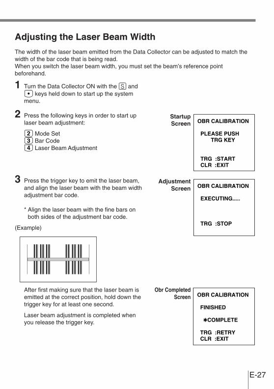
Adjusting the Laser Beam Width
The width of the laser beam emitted from the Data Collector can be adjusted to match thewidth of the bar code that is being read.When you switch the laser beam width, you must set the beam’s reference pointbeforehand.
1 Turn the Data Collector ON with the and keys held down to start up the system
menu.
2 Press the following keys in order to start uplaser beam adjustment:
Mode Set Bar Code Laser Beam Adjustment
3 Press the trigger key to emit the laser beam,and align the laser beam with the beam widthadjustment bar code.
* Align the laser beam with the fine bars onboth sides of the adjustment bar code.
(Example)
After first making sure that the laser beam isemitted at the correct position, hold down thetrigger key for at least one second.
Laser beam adjustment is completed whenyou release the trigger key.
OBR CALIBRATION
PLEASE PUSH TRG KEY
TRG :START CLR :EXIT
OBR CALIBRATION
EXECUTING.....
TRG :STOP
OBR CALIBRATION
FINISHED
✱COMPLETE
TRG :RETRY CLR :EXIT
StartupScreen
Obr CompletedScreen
AdjustmentScreen
E-28
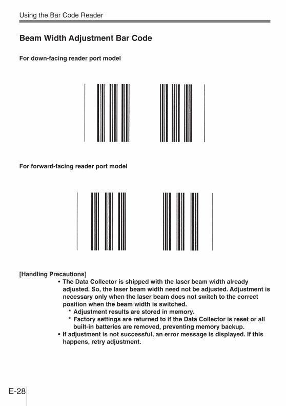
Beam Width Adjustment Bar Code
For down-facing reader port model
For forward-facing reader port model
[Handling Precautions]• The Data Collector is shipped with the laser beam width already
adjusted. So, the laser beam width need not be adjusted. Adjustment isnecessary only when the laser beam does not switch to the correctposition when the beam width is switched.
* Adjustment results are stored in memory.* Factory settings are returned to if the Data Collector is reset or all
built-in batteries are removed, preventing memory backup.• If adjustment is not successful, an error message is displayed. If this
happens, retry adjustment.
Using the Bar Code Reader

E-29
DT-900 - DT-900 Data Communication
Application software and input data can be transferred between two DT-900 units using theinfrared ports on the bottom of the units.Position the two DT-900 units so they will not accidently move during data communication.The orientation of the two units depends on the type ofcommunication you plan to perform.• Conformed IrDA Version 1.2:
0 (contact) to 20 centimeters or less enablescommunication
Data Communication

E-30
Specifications• General
CPU: 32-bit RISC TypeMemory: M50E/M51E RAM : 2MB (User area 1.6 MB)
FROM : 2MB (User area 500 KB)M60E/M61E RAM : 2MB (User area 1.6 MB)
FROM : 8MB (User area 6.3 MB)
• DisplayType: STN LCD with phase correction filmCapacity: 128 x 64 dotsDisplay contrast: Manually adjustableBacklight: EL backlight
• Laser ScannerReadable Codes: EAN, JAN, UPC, NW-7, CODE39, ITF, CODE93, CODE128, MSI,
Industrial 2 of 5, IATAMaximum Non-contact Distance:
Approx. 380 mm max.(forward-facing reader port model) DT-900 M51E/M61EApprox. 300 mm max.(down-facing reader port model) DT-900 M50E/M60E
• InputStroke Keys: 26
• Infrared CommunicationsInterface: Infrared (contact-less)Standard: Conforms to IrDA Ver. 1.2, OriginalControl Protocol: Half-duplexSynchronization: AsynchronousSpeed: 2,400 to 115,200 bpsCommunication Distance:
Conforms to IrDA Version 1.2: 0 (contact) to 20 centimeters or lessOriginal Communication: Contact
• 14-pin Serial Communications

E-31
Interface: Serial I/FControl Protocol: Full-duplexSynchronization: AsynchronousSpeed: 1,200 to 115,200 bps
• Power SupplyMain: Two AA (LR6)-size alkaline dry cells or one lithium-ion battery pack
Alkaline Battery life:- Approx. 150 hours (using a new set of AA (LR6)-size alkaline
batteries at normal temperature at a key standby/calculation/readoperation ratio of 20:1:1)
- Approx. 30 hours (using a new fully charged lithium-ion batterypack at normal temperature at a key standby/calculation/readoperation ratio of 20:1:1)
Backup: One CR2032 lithium batteryBattery life: Approx. one month (when only the backup battery is supplying
backup power)
• Size and WeightDimensions: Forward-facing reader port model
Approx. 56 <69> (W) x 173 (D) x 21.4 <32.5> (H) mmDown-facing reader port modelApprox. 56 <69> (W) x 179 (D) x 21.4 <41.4> (H) mmFigures in < > brackets don't include display and protrusions.
Weight: Forward-facing reader port model: 198 gDown-facing reader port model: 210 g
• Operating EnvironmentOperating temperature: -5 to 50° COperating humidity: 30% to 80% RHWater proofing: IPX2Drop test height: 150 cm
Lithium-Ion Battery Pack (DT-923LI)
Power Supply: Rated Capacitance: 600 mAhRated Voltage: 3.6 VDimensions: Approx. 29 (W) x 50.2 (D) x 14.5 (H) mmWeight: Approx. 30 g

E-32
CASIO
DATA
POWER
OF
F
PO
WE
R
ON
RS-232CRS-485-1 RS-485-2
AC ADAPTOR
CASIO
4
5
8
1114
13
14
10
12
8
6
7
1
32
9
Using the Basic CradleBasic Cradle (DT-960IOE) makes it possible to upload system data and file data betweenthe Data Collector and a personal computer.You can use optional 6-6 pin Modular Cables (DT-788RSC) to connect up to 16 BasicCradles. Use the RS-232C cable (DT-782RSC/DT-783RSC/DT-787AX) for connecting theCradle to a personal computer. The Basic Cradle can be located on a desk or table top, ormounted on a wall. When the Basic Cradle is mounted on a wall, be sure to use the wallmount unit (supplied).
General Guide
AC adaptor Spacers
Wall unit screwsWood screws
AccessoriesWall units
E-33
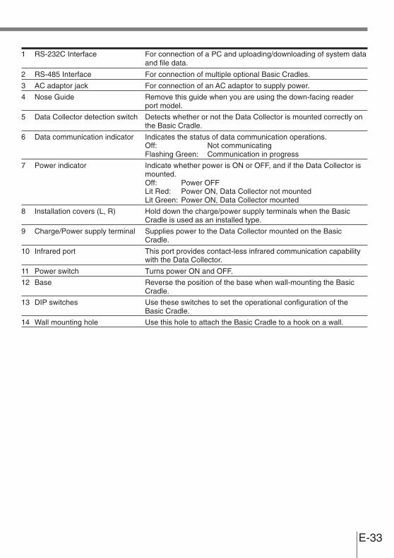
1 RS-232C Interface For connection of a PC and uploading/downloading of system dataand file data.
2 RS-485 Interface For connection of multiple optional Basic Cradles.
3 AC adaptor jack For connection of an AC adaptor to supply power.
4 Nose Guide Remove this guide when you are using the down-facing readerport model.
5 Data Collector detection switch Detects whether or not the Data Collector is mounted correctly onthe Basic Cradle.
6 Data communication indicator Indicates the status of data communication operations.Off: Not communicatingFlashing Green: Communication in progress
7 Power indicator Indicate whether power is ON or OFF, and if the Data Collector ismounted.Off: Power OFFLit Red: Power ON, Data Collector not mountedLit Green: Power ON, Data Collector mounted
8 Installation covers (L, R) Hold down the charge/power supply terminals when the BasicCradle is used as an installed type.
9 Charge/Power supply terminal Supplies power to the Data Collector mounted on the BasicCradle.
10 Infrared port This port provides contact-less infrared communication capabilitywith the Data Collector.
11 Power switch Turns power ON and OFF.
12 Base Reverse the position of the base when wall-mounting the BasicCradle.
13 DIP switches Use these switches to set the operational configuration of theBasic Cradle.
14 Wall mounting hole Use this hole to attach the Basic Cradle to a hook on a wall.

E-34
Using the Basic Cradle
When You Are Using the Down-facing Reader Port Model
When you are using a down-facing reader port model, remove the nose guide before use.To remove the nose guide, remove the twoscrews using a screwdriver.
Setting up the Communication Unit and Connectingthe Data Collector
Use only the specified AC Adaptor for Communication Unit to connect to an electrical outlet.Be sure to connect the AC adaptor and turn on Communication Unit power beforeperforming any data communication operation with the Data Collector. Power is supplied tothe Data Collector by the Communication Unit.
1 Plug the AC adaptor into an electrical outlet.
2 After making sure that the power switch of theCommunication Unit is in the OFF position,plug the other end of the AC adaptor into theAC terminal at the top of the CommunicationUnit.
3 After making sure that the power of theCommunication Unit and personal computeris OFF, remove the cover and connect oneend of the optional RS-232C cable (DT-782RSC, DT-783RSC, DT-787AX) to the RS-232C connector at the top of theCommunication Unit. Connect the other endof the cable to the computer’s RS-232Cconnector. When the RS-232C connector isnot used, attach the cover.
Powerswitch (OFF)
To electrical outlet

E-35
4 Turn on the Basic Cradle. The power indicatoron the Basic Cradle lights red.
5 Attach the Data Collector to the Basic Cradle,making sure their infrared ports come intoclose contact with each other. The color of theBasic Cradle power supply indicator changesto green when proper connection is achieved.The data communication indicator flashesgreen when data communication starts.
Important! • High-sensitivity communications devices are used for the IrDAcommunications function.Avoid using units or equipment such as a cellular phone emits radiowaves during data communication.To ensure uninterrupted data communication, keep the Basic Cradleaway from the equipment (at least 30 centimeters from a cellularphone).
Infrared port
Powerswitch (ON)
Data communication indicator
Power indicator

E-36
Using the Basic Cradle
Serial Connection of Multiple Basic Cradles
You can use optional 6-6 pin Modular Cables (DT-788RSC) toconnect up to 16 Basic Cradles in a serial configuration. Thisconfiguration makes it possible to exchange databetween multiple Data Collectors and a personalcomputer.
ConnectionsFirst connect Basic Cradle RS-485-1 and then the RS- 485-2 ofthe Basic Cradle that you wantto connect to.
DIP Switch Settings
The following table shows the varioussettings that are available with the DIPswitches located on the back of the BasicCradle.
Important! • Other settings not shown here are for special-purpose modes, andshould not be used.
1 2 3 4 5 6 7 8
Data Collector - Basic CradleCommunication Speed
1 2 3
2,400bps OFF OFF OFF
9,600bps ON OFF OFF
19,200bps OFF ON OFF
38,400bps ON ON OFF
57,600bps OFF OFF ON
115,200bps ON OFF ON
Unused
Connection Type6 7
Host ComputerConnection ON ON(no linking)
Intermediate Unit OFF OFFin Linked Chain
Terminator Unit ON OFFin Linked Chain
RS-232C Control Signal Setting4 5
RS enabled ON –
ER enabled – ON
RS-232C cableTo host computer
6-6 pin ModularCable (DT-788RSC)

E-37
DT-960IOE Basic Cradle Specifications
InfraredInterface: Infrared (non-contact type)Standard: CASIO originalControl Protocol: Half-duplexSynchronization: AsynchronousSpeed: 2,400 to 115,200 bps
RS-232CControl Protocol: Half-duplexSynchronization: AsynchronousSpeed: 2,400 to 115,200 bps
RS-485Control Protocol: Half-duplexSynchronization: AsynchronousSpeed: 2,400 to 115,200 bps
Power SupplyMethod: Special AC adaptorPower Requirements: AC 230 V (DT-9020ADP-G)
AC 120 V (DT-9020ADP-U)Rated Input: DC 9.5 V, approx. 1,000 mA
FunctionsInfrared interfaceRS-232C interfaceRS-485 interface
Serial ConnectionUp to 16 units
Dimensions and WeightDesktop: Approx. 110 (W) x 220 (D) x 100 (H) mm
Approx. 400 gWall Mounted (with wall-mounting unit attached):
Approx. 110 (W) x 220 (D) x 110 (H) mmApprox. 410 g

E-38
CASIO
LINE
DATA
CHG2
CHG1
POWER
OF
F
PO
WE
R
ON
CASIO
RS-232CC-OUT C-IN
AC ADAPTOR
4
5
11
1518
17
1812
1314
16
11
678910
1
32
Using the Satellite CradleSatellite Cradle (DT-964IOE) makes it possible to upload system data and file data betweenthe Data Collector and a personal computer. It can also be used as the charger for thelithium-ion battery pack.Use the RS-232C cable (DT-881RSC/DT-882RSC/DT-883RSC/DT-887AX/AXA) forconnecting the Satellite Cradle to a personal computer. The Satellite Cradle can be locatedon a desk or table top, or mounted on a wall. When the Satellite Cradle is mounted on awall, be sure to use the wall mount unit (supplied).
General Guide
AC adaptor
AccessoriesSpacers
Wall unit screwsWood screws
Wall units

E-39
1 RS-232C Interface For connection to a PC and uploading/downloading of system dataand file data.
2 RS-422 Interface For connection of multiple Optional Satellite Cradles.
3 AC adaptor jack For connection of the AC adaptor to supply power.
4 Nose Guide Remove this guide when you are using the down-facing reader port model.
5 Data Collector detection switch Detects whether or not the Data Collector is mounted correctly onthe Satellite Cradle.
6 System operation indicator Indicates whether or not system operation is normal.A system operation problem is indicated when this indicator does not light up green shortly after the
Data Collector is mounted onto the Satellite Cradle.Off: All Data Collectors mounted on the Satellite Cradle are
unable to communicate, or there is a system problem.Lit Green: Normal system operation. One or more of the Data
Collectors mounted on the Satellite Cradles arecommunicating.
7 Data communication indicator Indicates the status of data communication operations.Off: Not communicatingFlashing Green: Communication in progressLit Red: Optional Communication Unit
connection problem
8 Battery pack charge indicator Indicates the charge status of the spare battery pack.Off: Not charging, or a battery pack problemLit Red: Charging (charging standing by when the battery in the
Data Collector is charging)Lit Green: Charging complete
9 Charge indicator Indicates the charge status of the lithium-ion battery pack in theData Collector.Off: Not charging (e.g. lithium-ion battery not loaded in Data
Collector) or a battery pack problemLit Red: ChargingLit Green: Charging complete
10 Power indicator Indicates whether power is ON or OFF, and if the Data Collector ismounted.Off: Power OFFLit Red: Power ON, Data Collector not mountedLit Green: Power ON, Data Collector mounted
11 Installation covers (L, R) Hold down the charge/power supply terminals when the SatelliteCradle is used as an installed type.
12 Charge/Power supply terminals Supplies power to the Data Collector mounted on the SatelliteCradle.
13 Battery pack charge terminals Charges the spare battery pack separately.
14 Infrared port This port provides contact-less infrared communication capabilitieswith a Data Collector.
15 Power switch Turns power ON and OFF.
16 Base Reverses the position of the base when wall-mounting the SatelliteCradle.
17 DIP switches Use these switches to set the operational configuration of theSatellite Cradle.
18 Wall mounting hole Use this hole to attach the Satellite Cradle to a hook on a wall.

E-40
Using the Satellite Cradle
When You Are Using the Down-facing Reader Port Model
When you are using a down-facing reader port model, remove the nose guide before use.To remove the nose guide, remove the twoscrews using a screwdriver.
Setting up the Satellite Cradle and Connecting the DataCollector
Use only the specified AC Adaptor for Satellite Cradle to connect to an electrical outlet. Besure to connect the AC adaptor and turn on Satellite Cradle power before performing anydata communication operation with the Data Collector. Power is supplied to the DataCollector by the Satellite Cradle.
1 Plug the AC adaptor into an electrical outlet.
2 After making sure that the power switch of theSatellite Cradle is in the OFF position, plugthe other end of the AC adaptor into the ACterminal at the top of the Satellite Cradle.
3 After making sure that the power of theSatellite Cradle and personal computer isOFF, remove the cover and connect one endof the optional RS-232C cable (DT- 881RSC,DT-882RSC, DT-883RSC, DT- 887AX/AXA)to the RS-232C connector at the top of theSatellite Cradle. Connect the other end of thecable to the computer’s RS- 232C connector.When the RS-232C connector is not used,attach the cover.
Powerswitch (OFF)
To electrical outlet
E-41
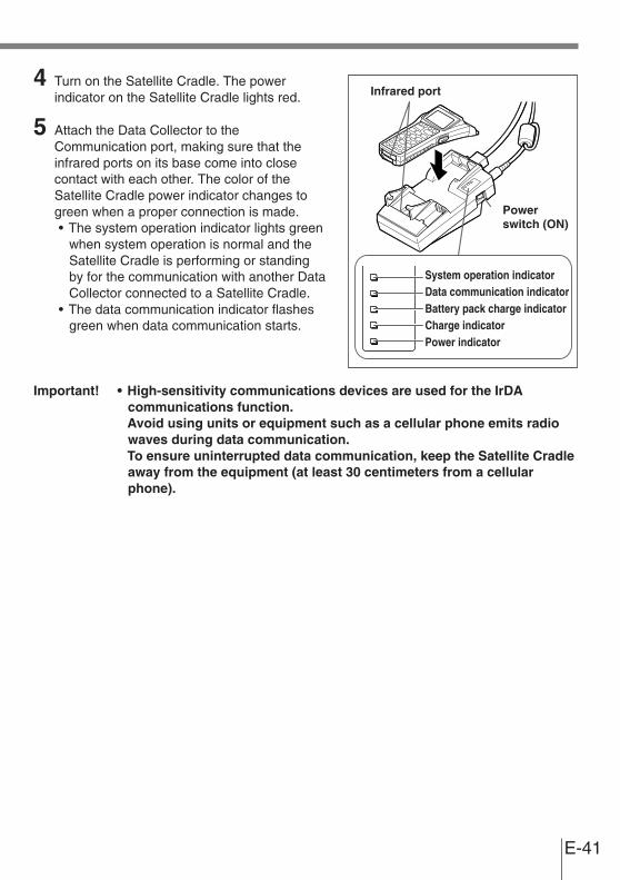
4 Turn on the Satellite Cradle. The powerindicator on the Satellite Cradle lights red.
5 Attach the Data Collector to theCommunication port, making sure that theinfrared ports on its base come into closecontact with each other. The color of theSatellite Cradle power indicator changes togreen when a proper connection is made.• The system operation indicator lights green
when system operation is normal and theSatellite Cradle is performing or standingby for the communication with another DataCollector connected to a Satellite Cradle.
• The data communication indicator flashesgreen when data communication starts.
Important! • High-sensitivity communications devices are used for the IrDAcommunications function.Avoid using units or equipment such as a cellular phone emits radiowaves during data communication.To ensure uninterrupted data communication, keep the Satellite Cradleaway from the equipment (at least 30 centimeters from a cellularphone).
Infrared port
Powerswitch (ON)
System operation indicator
Charge indicator
Data communication indicatorBattery pack charge indicator
Power indicator

E-42
Using the Satellite Cradle
Charging the Battery Pack
The following procedure can be used only when a lithium-ion battery pack is loaded in theData Collector.
1 Turn on the power of the Satellite Cradle, andconfirm that its power indicator lights up red.
2 Attach the Data Collector to the SatelliteCradle, making sure that the charge terminalson the rear of the Data Collector come intocontact with the charge terminals on theSatellite Cradle. The color of the SatelliteCradle power indicator changes to greenwhen proper connection is achieved. Thecharge indicator lights up red when chargingstarts.
Charge IndicatorLit Red: ChargingLit Green: Charging complete
When the charge indicator lights red andthen goes out after several seconds, thisindicates a battery problem.
Charging TimeApprox. 6 hours
[Warning]■ Pay Attention To The Ambient Temperature When Charging The Battery Pack
• Temperature ranges for battery pack use, charging, and storage arespecified below. Temperatures outside these ranges create the dangerof deterioration of battery pack performance and shortening of itsservice life, as well as fluid leakage and heat generation.
Operating Temperature: –5°C to 50°CCharging Temperature: 0°C to 40°CStorage Temperature: –20°C to 60°C
Important! • If the charge indicator does not light during charging, remove thebattery pack and then re-attach it. If this does not solve the problem, itmeans that the battery pack is defective and needs to be replaced.
• Use only the specified battery pack.• Battery packs naturally discharge even when they are not loaded in the
Data Collector. Use a battery pack as soon as possible after charging it.• For best charging results, keep the Satellite Cradle, Data Collector and
battery pack contacts clean by periodically wiping them off with acotton swab or dry cloth.
Charge terminals
Powerswitch (ON)
System operation indicator
Charge indicator
Data communication indicatorBattery pack charge indicator
Power indicator

E-43
Charging the Battery Pack(charging the lithium-ion battery pack separately)
1 Set the power switch of the Satellite Cradle tothe ON position. The power indicator of theSatellite Cradle lights red.
2 Load the battery pack in the Satellite Cradle,making sure that the terminals on the sideand rear of the battery pack come into closecontact with the battery pack chargeterminals.The battery pack charge indicator lights red,and charging is started.
Battery Pack Charge IndicatorLit Red: Charging (chargingstanding by when thebattery in the DataCollector is charging)Lit Green: Charging complete
• When the battery pack charging indicator lights red and then goes out after severalseconds, this indicates a battery pack problem.
• Charging of the battery in the Data Collector is given precedence. Separate chargingof the battery pack cannot be performed simultaneously while charging of the batteryin the Data Collector.
[Warning]■ Pay Attention To The Ambient Temperature When Charging The Battery Pack
• Temperature ranges for battery pack use, charging, and storage arespecified below. Temperatures outside these ranges create the dangerof deterioration of battery pack performance and shortening of itsservice life, as well as fluid leakage and heat generation.
Operating Temperature: –5°C to 50°CCharging Temperature: 0°C to 40°CStorage Temperature: –20°C to 60°C
Important! • If the battery pack charge indicator does not light during charging, removethe battery pack and then re-attach it. If this does not solve the problem, itmeans that the battery pack is defective and needs to be replaced.
• Use only the specified battery pack.• Battery packs naturally discharge even when they are not loaded in the
Data Collector. Use a battery pack as soon as possible after charging it.• For best charging results, keep the Satellite Cradle, Data Collector and
battery pack contacts clean by periodically wiping them off with acotton swab or dry cloth.
Battery pack
Powerswitch (ON)
System operation indicator
Charge indicator
Data communication indicatorBattery pack charge indicator
Power indicator
E-44
Using the Satellite Cradle
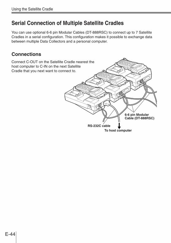
Serial Connection of Multiple Satellite Cradles
You can use optional 6-6 pin Modular Cables (DT-888RSC) to connect up to 7 SatelliteCradles in a serial configuration. This configuration makes it possible to exchange databetween multiple Data Collectors and a personal computer.
ConnectionsConnect C-OUT on the Satellite Cradle nearest thehost computer to C-IN on the next SatelliteCradle that you next want to connect to.
RS-232C cableTo host computer
6-6 pin ModularCable (DT-888RSC)
E-45
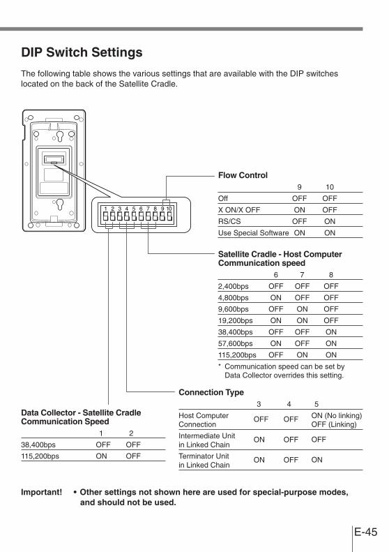
DIP Switch Settings
The following table shows the various settings that are available with the DIP switcheslocated on the back of the Satellite Cradle.
Important! • Other settings not shown here are used for special-purpose modes,and should not be used.
1 2 3 4 5 6 7 8 9 10
Data Collector - Satellite CradleCommunication Speed
1 2
38,400bps OFF OFF
115,200bps ON OFF
Connection Type3 4 5
Host Computer OFF OFF ON (No linking)Connection OFF (Linking)
Intermediate Unit ON OFF OFFin Linked Chain
Terminator Unit ON OFF ONin Linked Chain
Satellite Cradle - Host ComputerCommunication speed
6 7 8
2,400bps OFF OFF OFF
4,800bps ON OFF OFF
9,600bps OFF ON OFF
19,200bps ON ON OFF
38,400bps OFF OFF ON
57,600bps ON OFF ON
115,200bps OFF ON ON
* Communication speed can be set byData Collector overrides this setting.
Flow Control9 10
Off OFF OFF
X ON/X OFF ON OFF
RS/CS OFF ON
Use Special Software ON ON

E-46
DT-964IOE Satellite Cradle Specifications
InfraredInterface: InfraredStandard: Conforms to IrDA Ver. 1.2 OriginalSynchronization: AsynchronousSpeed: 9,600/38,400/115,200bps
RS-232CControl Protocol: Full-duplexSynchronization: AsynchronousSpeed: 1,200 to 115,200bps
RS-422Control Protocol: Full-duplexSynchronization: AsynchronousSpeed: 9,600/38,400/115,200bps
ChargerCharger Type: Fixed voltage (with current limiter)Charge Time: Approx. 6 hours
Power SupplyMethod: Special AC adaptorPower Requirements: 230 VAC (DT-825ADP-G)
120 VAC (DT-825ADP-U)Rated Input: DC 12 V, approx. 1,400 mA (during charging)
FunctionsInfrared interfaceRS-232C interfaceRS-422 interface
Dimensions and WeightDesktop: Approx. 110 (W) x 220 (D) x 100 (H) mm
Approx. 470 gWall Mounted (with wall-mounting unit attached):
Approx. 110 (W) x 220 (D) x 110 (H) mmApprox. 480 g
Using the Satellite Cradle

E-47
CHG2
CHG1
CASIO
POWER
OF
F
PO
WE
R
ON
AC ADAPTOR
CASIO
2
3
7
1012
128
9
11
7
456
1
Using the Charger UnitThe Charger Unit (DT-969CHGE) makes it possible to charge the battery pack on a DataCollector (with lithium-ion battery pack attached).The Charger Unit can be located on a desk or table top, or mounted on a wall. When theCharger Unit is mounted on a wall, be sure to use the wall mount unit (supplied).
General Guide
AC adaptor Spacers
Wall unit screwsWood screws
AccessoriesWall units

E-48
Using the Charger Unit
1 AC adaptor jack For connection of the AC adaptor to supply power
2 Nose Guide Remove this guide when you are using the down-facing readerport model.
3 Data Collector detection switch Detects whether or not the Data Collector is mounted correctly onthe Charger Unit.
4 Battery pack charge indicator Indicates the charge status of the spare battery pack.Off: Not charging, or a battery pack problemLit Red: Charging (charging standing by when the battery in the
Data Collector is charging)Lit Green: Charging complete
5 Charge indicator Indicates the charge status of the lithium-ion battery pack in theData Collector.Off: Not charging (e.g. lithium-ion battery not loaded in Data
Collector) or a battery pack problemLit Red: ChargingLit Green: Charging complete
6 Power indicator Indicates whether power is ON or OFF, and if the Data Collector ismounted.Off: Power OFFLit Red: Power ON, Data Collector not mountedLit Green: Power ON, Data Collector mounted
7 Installation covers (L, R) Hold down the charge/power supply terminals when the ChargerUnit is used as an installed type.
8 Charge/Power supply terminals Supplies power to the Data Collector mounted on the ChargerUnit.
9 Battery pack charge terminals Charges the spare battery pack separately.
10 Power switch Turns power ON and OFF.
11 Base Reverses the position of the base when wall-mounting the ChargerUnit.
12 Wall mounting hole Use this hole to attach the Charger Unit to a hook on a wall.
E-49
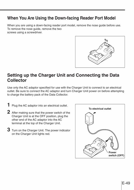
When You Are Using the Down-facing Reader Port Model
When you are using a down-facing reader port model, remove the nose guide before use.To remove the nose guide, remove the twoscrews using a screwdriver.
Setting up the Charger Unit and Connecting the DataCollector
Use only the AC adaptor specified for use with the Charger Unit to connect to an electricaloutlet. Be sure to connect the AC adaptor and turn Charger Unit power on before attemptingto charge the battery pack of the Data Collector.
1 Plug the AC adaptor into an electrical outlet.
2 After making sure that the power switch of theCharger Unit is at the OFF position, plug theother end of the AC adaptor into the ACterminal at the top of the Charger Unit.
3 Turn on the Charger Unit. The power indicatoron the Charger Unit lights red.
Powerswitch (OFF)
To electrical outlet

E-50
Using the Charger Unit
4 Attach the Data Collector to the Charger Unit,making sure the charge terminals on the backof the Data Collector come into contact withthe terminals of the Charger Unit.If the Data Collector is attached properly, thepower indicator lights green.Start of charging is indicated by the chargeindicator of the Charger Unit lighting red.
Charge IndicatorLit Red: ChargingLit Green: Charge complete
Charging TimeApprox. 6 hours
[Warning]■ Pay Attention To The Ambient Temperature When Charging The Battery Pack
• Temperature ranges for battery pack use, charging, and storage arespecified below. Temperatures outside these ranges create the dangerof deterioration of battery pack performance and shortening of itsservice life, as well as fluid leakage and heat generation.
Operating Temperature: –5°C to 50°CCharging Temperature: 0°C to 40°CStorage Temperature: –20°C to 60°C
Important! • If the charge indicator does not light during charging, remove thebattery pack and then re-attach it. If this does not solve the problem, itmeans that the battery pack is defective and needs to be replaced.
• Use only the specified battery pack.• Battery packs naturally discharge even when they are not loaded in the
Data Collector. Use a battery pack as soon as possible after charging it.• For best charging results, keep the Charger Unit, Data Collector and
battery pack contacts clean by periodically wiping them off with acotton swab or dry cloth.
Charge terminals
Powerswitch (ON)
Charge indicatorBattery pack charge indicator
Power indicator
E-51
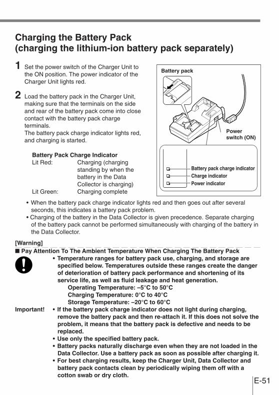
Charging the Battery Pack(charging the lithium-ion battery pack separately)
1 Set the power switch of the Charger Unit tothe ON position. The power indicator of theCharger Unit lights red.
2 Load the battery pack in the Charger Unit,making sure that the terminals on the sideand rear of the battery pack come into closecontact with the battery pack chargeterminals.The battery pack charge indicator lights red,and charging is started.
Battery Pack Charge IndicatorLit Red: Charging (charging
standing by when thebattery in the DataCollector is charging)
Lit Green: Charging complete
• When the battery pack charge indicator lights red and then goes out after severalseconds, this indicates a battery pack problem.
• Charging of the battery in the Data Collector is given precedence. Separate chargingof the battery pack cannot be performed simultaneously with charging of the battery inthe Data Collector.
[Warning]■ Pay Attention To The Ambient Temperature When Charging The Battery Pack
• Temperature ranges for battery pack use, charging, and storage arespecified below. Temperatures outside these ranges create the dangerof deterioration of battery pack performance and shortening of itsservice life, as well as fluid leakage and heat generation.
Operating Temperature: –5°C to 50°CCharging Temperature: 0°C to 40°CStorage Temperature: –20°C to 60°C
Important! • If the battery pack charge indicator does not light during charging,remove the battery pack and then re-attach it. If this does not solve theproblem, it means that the battery pack is defective and needs to bereplaced.
• Use only the specified battery pack.• Battery packs naturally discharge even when they are not loaded in the
Data Collector. Use a battery pack as soon as possible after charging it.• For best charging results, keep the Charger Unit, Data Collector and
battery pack contacts clean by periodically wiping them off with acotton swab or dry cloth.
Battery pack
Powerswitch (ON)
Charge indicatorBattery pack charge indicator
Power indicator
E-52
DT-969CHGE Charger Unit Specifications
ChargerCharger Method: Fixed voltage (with current limiter)Charge Time: Approx. 6 hours
Power SupplyMethod: Special AC adaptorPower Requirements: 230 VAC (DT-9020ADP-G)
120 VAC (DT-9020ADP-U)Rated Input: DC 9.5 V, approx. 1,000 mA
Dimensions and WeightDesktop: Approx. 110 (W) x 220 (D) x 100 (H) mm
Approx. 420 gWall Mounted (with wall-mounting unit attached):
Approx. 110 (W) x 220 (D) x 110 (H) mmApprox. 430 g
Using the Charger Unit

E-53
The following describes how to set up the Basic Cradle, Satellite Cradle and Charger Unit.You can set up these three types in one of two ways, on a wall or on a desktop.
To use the Basic Cradle / Satellite Cradle on a desktop(example: Satellite Cradle)
1 Simply place the Satellite Cradle on a desk,table, or any other flat, stable surface, rubberfeet down. You can even use the woodscrews to anchor the base onto a horizontalsurface. If you do not anchor the base, makesure you locate the Satellite Cradle wherethere is no danger of it falling. The nose guideis needed when you are using the forward-facing reader port model.
To hang the Basic Cradle / Satellite Cradle on a wall(example: Satellite Cradle)
1 Attach the wall unit screw.When you are using the down-facing readerport model, remove the nose guide attachedto the Data Collector, and attach the wall unitscrew to A using the screws (supplied).When you are using the forward-facing readerport model, attach the wall unit screw to Busing the screws (supplied) with the noseguide still attached.
CA
L
D
P
H
P
AB
Setting the Unit
Down-facingreader port model
Forward-facingreader port model

E-54
Setting the Unit
2 Remove the installation covers (L, R).
3 Attach the wall units. Insert the wall units intothe holes, and then fix them in place by slidingthem downwards.
4 Remove the two screws (one each at the topand bottom) that secure the base to theSatellite Cradle.
5 Pressing down on the four corners of theSatellite Cradle base, unhook the tabs, andremove the base from the unit.

E-55
6 Position the base on the wall where you wantto hang the Satellite Cradle, and use an awlor some other sharp object to mark thepositions of the two wood screws.
7 Slip a spacer over each of the wood screwsand then drive the screws into the wall at thepositions you marked in the previous step.Make sure that the spacers are orientedcorrectly. You will not be able to hook theSatellite Cradle onto the screws if the spacersare backwards.
8 Re-attach the base to the Satellite Cradle,orienting it upside-down from its originalmounting position when you removed it, andsecure it in place with the two screws.
9 Hook the Satellite Cradle onto the wall unitscrews in the wall, and slide it down to lock inplace.
Important! • Be sure to check the wood screws periodically for looseness andtighten if necessary after hanging the Satellite Cradle on a wall.