
D’Angelo COTR U.S. Department of the Interior Mineral ...R 627 – Inspection Methodologies for...
31
Energo Engineering, Inc. 3100 Wilcrest Drive, Suite 240 Houston, TX 77042 USA Tel: 713-532-2900 Fax: 713-532-2922 www.energoeng.com 30 January 2009 Energo Project No.: E08147 Lori D’Angelo COTR U.S. Department of the Interior Mineral Management Service Engineering and Research Branch 381 Elden Street Herndon, VA 20170 Subject: MMS TA&R Project 627 – Inspection Methodologies for Offshore Wind Turbine Facilities – Final Report Dear Lori: The following is our Final Report documenting the development of the Offshore Wind Turbine Inspection Guidelines (attached). This revision includes modifications based on comments received at our final meeting on January 27. This report and attached guidelines are the final deliverables for this project along with the management summary presentation delivered on the 27 th . Please let us know if you have any questions or comments. Sincerely, Energo Engineering, Inc. Robert Sheppard, P.E. Frank Puskar, P.E. Principal Consultant Principal Investigator
Transcript of D’Angelo COTR U.S. Department of the Interior Mineral ...R 627 – Inspection Methodologies for...
Energo Engineering, Inc. 3100 Wilcrest Drive, Suite 240 Houston, TX 77042 USA Tel: 713-532-2900 Fax: 713-532-2922
www.energoeng.com
30 January 2009 Energo Project No.: E08147
Lori D’Angelo
COTR
U.S. Department of the Interior
Mineral Management Service
Engineering and Research Branch
381 Elden Street
Herndon, VA 20170
Subject: MMS TA&R Project 627 – Inspection Methodologies for Offshore Wind
Turbine Facilities – Final Report
Dear Lori:
The following is our Final Report documenting the development of the Offshore Wind
Turbine Inspection Guidelines (attached). This revision includes modifications based on
comments received at our final meeting on January 27.
This report and attached guidelines are the final deliverables for this project along with
the management summary presentation delivered on the 27th.
Please let us know if you have any questions or comments.
Sincerely,
Energo Engineering, Inc.
Robert Sheppard, P.E. Frank Puskar, P.E.
Principal Consultant Principal Investigator

TA&R 627 – Inspection Methodologies for Offshore Wind Turbine Facilities Page 2
Final Report January 2009
Energo Engineering, Inc. 3100 Wilcrest Drive, Suite 240 Houston, TX 77042 USA Tel: 713-532-2900 Fax: 713-532-2922
www.energoeng.com
TABLE OF CONTENTS
Executive Summary ........................................................................................................ 3 1.0 Development Approach ........................................................................................ 4
2.0 Survey of Existing Data ........................................................................................ 4 3.0 Subject Matter Expert Input ................................................................................ 11
4.0 Recommended Inspection Guidelines ................................................................. 12 5.0 References .......................................................................................................... 12
Attachment A – Inspection Guidelines for Offshore Wind Turbine Facilities

TA&R 627 – Inspection Methodologies for Offshore Wind Turbine Facilities Page 3
Final Report January 2009
Energo Engineering, Inc. 3100 Wilcrest Drive, Suite 240 Houston, TX 77042 USA Tel: 713-532-2900 Fax: 713-532-2922
www.energoeng.com
EXECUTIVE SUMMARY
With the expected introduction of wind turbine facilities for the generation of electricity in
US Offshore Continental Shelf (OCS) waters, there is a need to evaluate how the long term
operations of these facilities can be ensured through Integrity Management (IM) activities,
particularly inspection. There is a long operational history of IM in the Gulf of Mexico,
offshore California, offshore Alaska and around the world for fixed and floating oil and gas
platforms for drilling and production. Both prescriptive and Risk-Based Inspection (RBI)
programs have been implemented to direct inspection operations for these facilities. This
experience provides a foundation for developing inspection guidelines for offshore wind
turbine structures and systems.
Current offshore practice is to use prescriptive or risk-based methodologies for inspections
of both above and below water components. The latter is now allowed under new Code of
Federal Regulations (CFR) language and has been used for both fixed and floating assets.
While still evolving, the process of developing these inspection programs has worked
successfully for offshore platforms and can be applied to wind turbine facilities.
This report documents the development of an IM methodology, including inspection and
monitoring, for wind turbine structures operating in the US OCS. The approach combines
existing methodologies used for wind turbine structures in other regions, current practice for
fixed platform structures, and input from a panel of industry experts focused on evaluating
specific parts of the wind turbine facility.
Attached to this report are inspection guidelines developed following the approach
documented herein. These guidelines identify inspection priorities, inspection frequencies,
data management and other factors necessary for implementing an efficient and effective
inspection program for offshore wind turbine facilities.

TA&R 627 – Inspection Methodologies for Offshore Wind Turbine Facilities Page 4
Final Report January 2009
Energo Engineering, Inc. 3100 Wilcrest Drive, Suite 240 Houston, TX 77042 USA Tel: 713-532-2900 Fax: 713-532-2922
www.energoeng.com
1.0 DEVELOPMENT APPROACH
The development of the inspection guidelines was divided into three tasks:
1. Survey of Existing Data
2. Subject Matter Expert Input
3. Recommended Inspection Guidelines
The concept was to integrate the extensive experience of both above and below water
inspection of offshore oil and gas platforms, especially in the Gulf of Mexico, with
inspection practices that are unique to wind turbine facilities both in the US and in other
parts of the world where these turbines are already operating offshore.
Part of the initial task was to gather data on the range of technologies incorporated in wind
turbine facilities both onshore and offshore. Evaluation of existing regulatory and industry
practice for inspecting these facilities was a useful guide to framing the guidelines being
developed.
This initial framework was then augmented using input from industry experts familiar with
the design and operation of wind turbine facilities. This expertise highlighted critical
inspection locations and identified practical inspection realities (e.g., what can be accessed
and how can areas be inspected) important to developing a useful set of guidelines.
This combination of established offshore inspection practice with the unique aspects of wind
turbine facilities resulted in a set of inspection guidelines that can be used to effectively
monitor the condition and proactively address anomalies that may occur during the service
life of these facilities.
2.0 SURVEY OF EXISTING DATA
This task focused on a literature search and a survey of existing guidelines and regulations
currently used for inspecting the structural and mechanical systems involved in the wind
turbine facilities. Part of this effort included attending the 2008 Windpower conference held
in Houston in early June. The conference proved a useful place to gather data on the wind
industry in general, offshore specific information related to areas of concern and research
(e.g., design parameters and seabed scour), and identify key players for inclusion in the
expert panel.
2.1 Wind Turbine Facility Technology
A combination of data gathered at the conference and data obtained via the internet or
through purchasing publications was evaluated to develop an understanding of important
areas related to inspection and current industry practice.
As to the technology currently employed to install wind turbine facilities offshore, they are,
from the tower structure and above, much the same as wind turbine facilities onshore. The

TA&R 627 – Inspection Methodologies for Offshore Wind Turbine Facilities Page 5
Final Report January 2009
Energo Engineering, Inc. 3100 Wilcrest Drive, Suite 240 Houston, TX 77042 USA Tel: 713-532-2900 Fax: 713-532-2922
www.energoeng.com
supporting substructure and subsea equipment are where the primary differences occur.
Figures 2.1 and 2.2 show the various parts of typical offshore wind turbine facilities that are
likely to be installed offshore in US waters.
The facilities can be divided into specific areas from a structural integrity management
standpoint: subsea structure, subsea equipment, above water structure, above water
equipment, and blades. The subsea structure supports the tower, turbine, blades and other
equipment and is generally piled into the seafloor. Subsea equipment generally consists of
cables and j-tubes or other structure to protect the cables, buried cables between facilities or
to the shore, junction boxes and other equipment. The above water structure consists of the
tower structure mounted on the subsea structure and the nacelle which houses the turbine
and other equipment, and may include a helicopter abseil platform. Cables/J-tubes run up
the tower to the nacelle. The blades are attached to the turbine equipment outboard of the
nacelle. Access systems include boat landings, stairs, platforms, handrails, etc.
Existing installations favor the monopile subsea support system though there are design
concepts that use a more traditional braced frame jacket support system. In either case, these
subsea systems are similar to designs used for offshore oil and gas platforms and experience
from that industry is directly applicable.
Monopile substructure(Subsea Structure)
Turbine support tower(Above Water Structure)
Tower/substructureconnection
Cables/J-tube andConnectors (Above Waterand Subsea Equipment)
Buried cables(Subsea Equipment)
Access platforms/ladders(Above Water Access Systems)
Figure 2.1 – Typical Offshore Facility from Mudline to Tower Structure

TA&R 627 – Inspection Methodologies for Offshore Wind Turbine Facilities Page 6
Final Report January 2009
Energo Engineering, Inc. 3100 Wilcrest Drive, Suite 240 Houston, TX 77042 USA Tel: 713-532-2900 Fax: 713-532-2922
www.energoeng.com
Turbine support tower(Above Water Structure)
Cables/J-tube andConnectors(Above Water Equipment)
Access platforms/ladders(Above Water Access)
Nacelle(Above Water Structure)
Blades
Figure 2.2 – Typical Offshore Facility from Tower Structure to Blades
A range of generation capacity is available for each turbine, from a few kilowatts to several
megawatts per facility. It is expected that units in the megawatt generating capacity will be
used primarily for most significant offshore wind farms to maximize their power generation
capacity. Regardless of the capacity of the generation equipment, all the previously
discussed parts of the facility are required.
Of particular interest is how blades respond to an offshore environment and what
degradations affect them. Figures 2.3 through 2.5 demonstrate the kind of mechanisms that
affect blades leading to erosion and other blade damage that should be identified as part of
an inspection program.

TA&R 627 – Inspection Methodologies for Offshore Wind Turbine Facilities Page 7
Final Report January 2009
Energo Engineering, Inc. 3100 Wilcrest Drive, Suite 240 Houston, TX 77042 USA Tel: 713-532-2900 Fax: 713-532-2922
www.energoeng.com
Figure 2.3 – Leading Edge Erosion
Figure 2.4 – Severe Blade Damage and Delamination
Figure 2.5 – Lightning Damage to Blade

TA&R 627 – Inspection Methodologies for Offshore Wind Turbine Facilities Page 8
Final Report January 2009
Energo Engineering, Inc. 3100 Wilcrest Drive, Suite 240 Houston, TX 77042 USA Tel: 713-532-2900 Fax: 713-532-2922
www.energoeng.com
For multiple unit wind farms it is expected that there will be a service platform to which all
the turbines will send their generated electricity. From there, equipment and cables will send
the power to shore-based equipment. These service platforms will be similar to existing
offshore oil and gas platforms and their inspection requirements will likely be addressed via
the same guidelines used for those facilities (e.g., API RP 2A [Ref. 7]).
2.2 Offshore Oil and Gas Industry
Because of similarities of design and materials, it is expected that experience with offshore
oil and gas facilities will be directly applicable to especially the subsea portion of offshore
wind turbine facilities. In US waters there is significant operational experience for Gulf of
Mexico structures but also for platforms offshore the West Coast and Alaska.
Issues such as corrosion, fatigue, mechanical damage (e.g., from dropped objects and vessel
impact), and structural response to extreme events (e.g., hurricanes) is fairly well
understood. Guidance found in API RP 2A and 2-SIM is directly applicable for the
supporting structures of wind turbine facilities.
The following figures show examples of the kind of damage and anomalies found in
offshore oil and gas structures that can be expected for wind turbine facilities as well. In
Figure 2.6 the kind of cracking that can occur due to fatigue damage is shown (along with
typical marine growth prevalent in shallower portions of the submerged structure).
Inspections of subsea structure are intended to locate these kinds of issues so that remedial
action can be taken before the joint fails and the structural strength is compromised.
HORIZONTAL
(BRACE)
LEG
(CHORD)
CRACK
Figure 2.6 – Typical Fatigue Crack at Welded Connection

TA&R 627 – Inspection Methodologies for Offshore Wind Turbine Facilities Page 9
Final Report January 2009
Energo Engineering, Inc. 3100 Wilcrest Drive, Suite 240 Houston, TX 77042 USA Tel: 713-532-2900 Fax: 713-532-2922
www.energoeng.com
Figure 2.7 – Typical Separated Brace
Figure 2.7 shows a typical subsea k-brace that has separated from the main horizontal
member. This is typical of storm damage at a vertical brace and would be identified by a
post-event inspection.
VD
VD
Figure 2.8 – Buckled Braces
The strength of environmental forces is demonstrated in Figure 2.8. This figures shows two
different vertical braces that have been buckled by storm loads. Post-event inspections
should identify these kinds of issues.
In Figure 2.9 a hole caused by corrosion damage can be seen. Properly maintained cathodic
protection systems do a good job of preventing corrosion damage underwater, but the
TA&R 627 – Inspection Methodologies for Offshore Wind Turbine Facilities Page 10
Final Report January 2009
Energo Engineering, Inc. 3100 Wilcrest Drive, Suite 240 Houston, TX 77042 USA Tel: 713-532-2900 Fax: 713-532-2922
www.energoeng.com
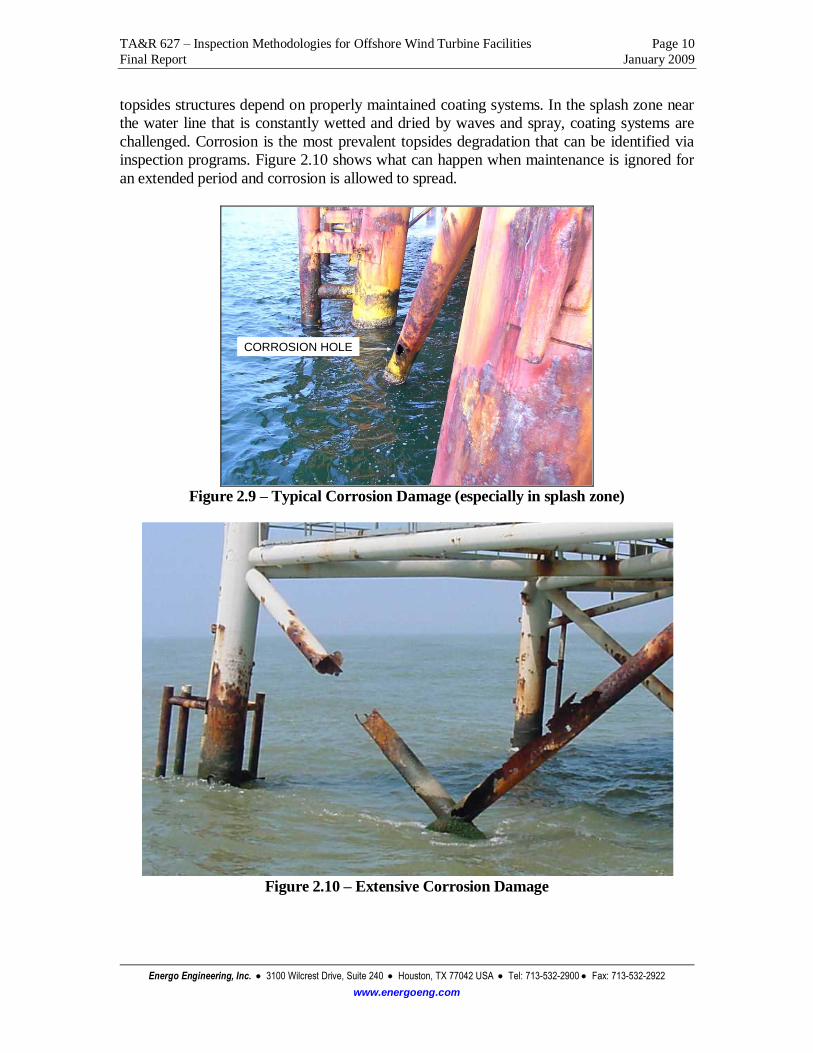
topsides structures depend on properly maintained coating systems. In the splash zone near
the water line that is constantly wetted and dried by waves and spray, coating systems are
challenged. Corrosion is the most prevalent topsides degradation that can be identified via
inspection programs. Figure 2.10 shows what can happen when maintenance is ignored for
an extended period and corrosion is allowed to spread.
CORROSION HOLE
Figure 2.9 – Typical Corrosion Damage (especially in splash zone)
Figure 2.10 – Extensive Corrosion Damage

TA&R 627 – Inspection Methodologies for Offshore Wind Turbine Facilities Page 11
Final Report January 2009
Energo Engineering, Inc. 3100 Wilcrest Drive, Suite 240 Houston, TX 77042 USA Tel: 713-532-2900 Fax: 713-532-2922
www.energoeng.com
2.3 Classification Societies
Various Classification Societies are developing or have developed guidelines or rules related
to onshore and offshore wind turbine facilities. The American Bureau of Shipping (ABS) is
in the process of developing guidelines and have a representative on the panel of experts
involved in this project. Other guides and standards reviewed were developed by Det
Norske Veritas (DNV), Germanischer Lloyd (GL), and the International Electrotechnical
Commision (IEC).
Two DNV documents were obtained: DNV-OS-J101, Design of Offshore Wind Turbine
Structures and DNV-OS-J102, Design and Manufacture of Wind Turbine Blades, Offshore
and Onshore Wind Turbines. Together, these documents provided an overview of design
parameters recommended for wind turbine facilities, including those to be installed offshore,
as well as guidance on inspection intervals, techniques and areas to inspect.
Three GL documents were obtained: Guideline for the Certification of Wind Turbines,
Guideline for the Certification of Offshore Wind Turbines, and Guideline for the
Certification of Condition Monitoring Systems for Wind Turbines. These documents
provide guidance from a second classification society on the design and ongoing monitoring
of wind turbine facilities, including specific guidance for offshore installations. The GL
documents were more focused on maintenance of the equipment systems rather than
integrity of the structures.
The IEC document, IEC 61400-3, Ed. 1, Design requirements for offshore wind turbines,
was also reviewed. While this document does not contain specific guidance on ongoing
inspections (though it does contain some general information), it does have useful
information on the design parameters to be addressed which is useful in identifying
important degradation mechanisms and in-service events.
These documents provided both background data on the systems to be included in the
inspection guidelines and information on current inspection practices including frequency of
inspection and inspection techniques.
3.0 SUBJECT MATTER EXPERT INPUT
In order to expand on information available from Task 1, a panel of subject matter experts
was solicited to provide input from their own perspective on the wind turbine industry. The
panelists volunteered their time in this effort. The panel includes:
Sandy Butterfield Chief Engineer National Renewable Energy Laboratory
Walt Musual Principal Engineer National Renewable Energy Laboratory
Jim Manwell Professor & Director of RERL University of Massachusetts
Gary Kanaby Director of Business Development Knight & Carver Wind Group
Dr. Roger Basu Director, Research & Product Devel. American Bureau of Shipping
Dr. Malcolm Sharples President Offshore Risk and Technology
Morten Andersen Senior Engineer DNV Global Energy Concepts

TA&R 627 – Inspection Methodologies for Offshore Wind Turbine Facilities Page 12
Final Report January 2009
Energo Engineering, Inc. 3100 Wilcrest Drive, Suite 240 Houston, TX 77042 USA Tel: 713-532-2900 Fax: 713-532-2922
www.energoeng.com
All panelists were provided with a survey to solicit specific feedback in the following
areas:
critical inspection areas for all parts of the facility,
inspection frequencies,
inspection techniques,
regional variations,
other data sources and
post-event inspections.
These surveys were seeded with data gathered from the Task 1 results to prompt their
feedback. This was intended to make the best use of their time and focus their efforts.
Additionally, the panelists were provided with an outline of the guideline document so
they could comment on the layout and content of the final document.
The input from the panelists was then used to take the guideline outline and expand it into
the inspection guidelines attached to this report. Further, the panelists were asked to
provide further review and comments on the draft guidelines before they were finalized.
4.0 RECOMMENDED INSPECTION GUIDELINES
Information from the data survey and the expert panel was used to develop the inspection
guideline document. This document provides data to guide an operator through the
process of developing an inspection program for their offshore wind turbine assets from
the standpoint of structural integrity. It also provides guidance on overall integrity
management including data collection and interpretation, and response to anomalous
conditions and events (e.g., hurricanes).
The guidelines have been organized in the form of other guideline documents used for
integrity management programs for offshore facilities. They are included in this report as
an attachment since they are presented in a standalone document format.
5.0 REFERENCES
1. DNV-OS-J101, Design of Offshore Wind Turbine Structures
2. DNV-OS-J102, Design and Manufacture of Wind Turbine Blades, Offshore and Onshore
Wind Turbines
3. GL Wind 2003, Guideline for the Certification of Wind Turbines, Edition 2003.
4. GL Wind 2005, Guideline for the Certification of Offshore Wind Turbines, Edition 2005.
5. GL 2007, Guideline for the Certification of Condition Monitoring Systems for Wind
Turbines, Edition 2007.
6. IEC 61400-3, Ed. 1, Design requirements for offshore wind turbines
7. API Recommended Practice 2A, RP-2A, Recommended Practice for Planning,
Designing and Constructing Fixed Offshore Platforms, 21st Edition.
8. ISO 19902, Petroleum and Natural Gas Industries, Fixed Steel Offshore Structures.

TA&R 627 – Inspection Methodologies for Offshore Wind Turbine Facilities Attachment A
Final Report January 2009
Energo Engineering, Inc. 3100 Wilcrest Drive, Suite 240 Houston, TX 77042 USA Tel: 713-532-2900 Fax: 713-532-2922
www.energoeng.com
Attachment A
Inspection Guidelines for
Offshore Wind Turbine Facilities

Inspection Guidelines for Offshore Wind Turbine Facilities Page 1 of 16
Final Draft January 2009
Energo Engineering, Inc. 3100 Wilcrest Drive, Suite 240 Houston, TX 77042 USA Tel: 713-532-2900 Fax: 713-532-2922
www.energoeng.com
Table of Contents
Acronyms, Abbreviations and Definitions ....................................................................... 2
I. Overview and Scope ............................................................................................ 4
II. Frequency of Inspections ..................................................................................... 4
III. Subsea Structure .................................................................................................. 5
IV. Subsea Equipment ............................................................................................... 8
V. Above Water Structural and Access Systems ....................................................... 9
VI. Above Water Electrical and Mechanical Systems ............................................... 10
VII. Blades ................................................................................................................ 11
VIII. Post-Event Inspections ....................................................................................... 12
IX. Engineering Evaluation ...................................................................................... 13
X. Data Requirements............................................................................................. 13
XI. Regional Variations ........................................................................................... 14
Appendix A: Sample checklists and data reporting

Inspection Guidelines for Offshore Wind Turbine Facilities Page 2 of 16
Final Draft January 2009
Energo Engineering, Inc. 3100 Wilcrest Drive, Suite 240 Houston, TX 77042 USA Tel: 713-532-2900 Fax: 713-532-2922
www.energoeng.com
Acronyms, Abbreviations and Definitions
CP Cathodic Protection
CVI Close Visual Inspection
GVI General Visual Inspection
MMS Minerals Management Service
MPI Magnetic Particle Inspection
NDE Non-destructive Examination
NDT Non-destructive Testing
OSTS Office of Structural and Technical Support
ROV Remotely Operated Vehicle
RVI Remote Visual Inspection
UT Ultrasonic Testing
Anomaly: An observed or measured condition which is outside the threshold considered
acceptable from the design or most recent fitness-for-purpose assessment.
Condition Assessment: Information that should be gathered on the facility’s present
condition to perform a fitness-for-purpose assessment.
Corrosion: A component defect categorized as either general or local that manifests itself
as either pitting, hole, fretting and/or crevice.
CP measurement: A measurement to determine the effectiveness of the CP system by
measuring the cathodic potential at a location typically using a probe held by a diver or
ROV system or using a drop cell device from above water.
Defect: An imperfection, fault, flaw or blemish in a component that can include
mechanical damage, corrosion and weld defects.
Design Life: The planned time period from initial installation or use until permanent
decommissioning.
Deterioration: The reduction in the ability of a component to provide its intended
purpose.
Extreme Event: An extreme metocean, seismic and/or ice condition, which a structure
may be subjected to during its operational life.
Fitness-For-Purpose: An existing structure is considered fit-for-purpose if it can be
demonstrated that it has adequate strength to resist the imposed assessment loads
(functional, metocean, seismic and/or ice).
Inspection: The visit to the facility for purposes of collecting data important to its
structural integrity and continued operation.
Mechanical damage: A defect type that includes dents, bows, gouges, holes and separated
or severed members.
Mitigation: Strengthening, modification or repairs and/or operational procedures that
reduce loads or increase capacities.

Inspection Guidelines for Offshore Wind Turbine Facilities Page 3 of 16
Final Draft January 2009
Energo Engineering, Inc. 3100 Wilcrest Drive, Suite 240 Houston, TX 77042 USA Tel: 713-532-2900 Fax: 713-532-2922
www.energoeng.com
Mudline: The sea floor.
Nacelle: The structure that houses the generating components, gearbox, drive train, etc. of
a wind turbine facility.
OCS: Outer Continental Shelf, a term used primarily in the U.S. for the offshore areas
under federal jurisdiction.
Operator: Those employed by the Owners to conduct operations.
Owner: A party who owns physical infrastructure assets and/or a party who owns
capacity rights in those physical assets but does not own the asset itself.
Prior Exposure: The historical exposure of a facility to the design metocean, seismic or
ice loading.
Repair: The work necessary to restore a facility to a condition deemed fit-for-purpose.
Risk-Based Inspection: The development of inspection strategies based an assessment of
the facility’s risk.
Splash Zone: The area of the structure that is intermittently wet and dry due to wave and
tidal action.
Survey: A specific visual or non-destructive examination of one or more components.
Collectively, the surveys make up the complete inspection.
Inspection Guidelines for Offshore Wind Turbine Facilities Page 4 of 16
Final Draft January 2009
Energo Engineering, Inc. 3100 Wilcrest Drive, Suite 240 Houston, TX 77042 USA Tel: 713-532-2900 Fax: 713-532-2922
www.energoeng.com
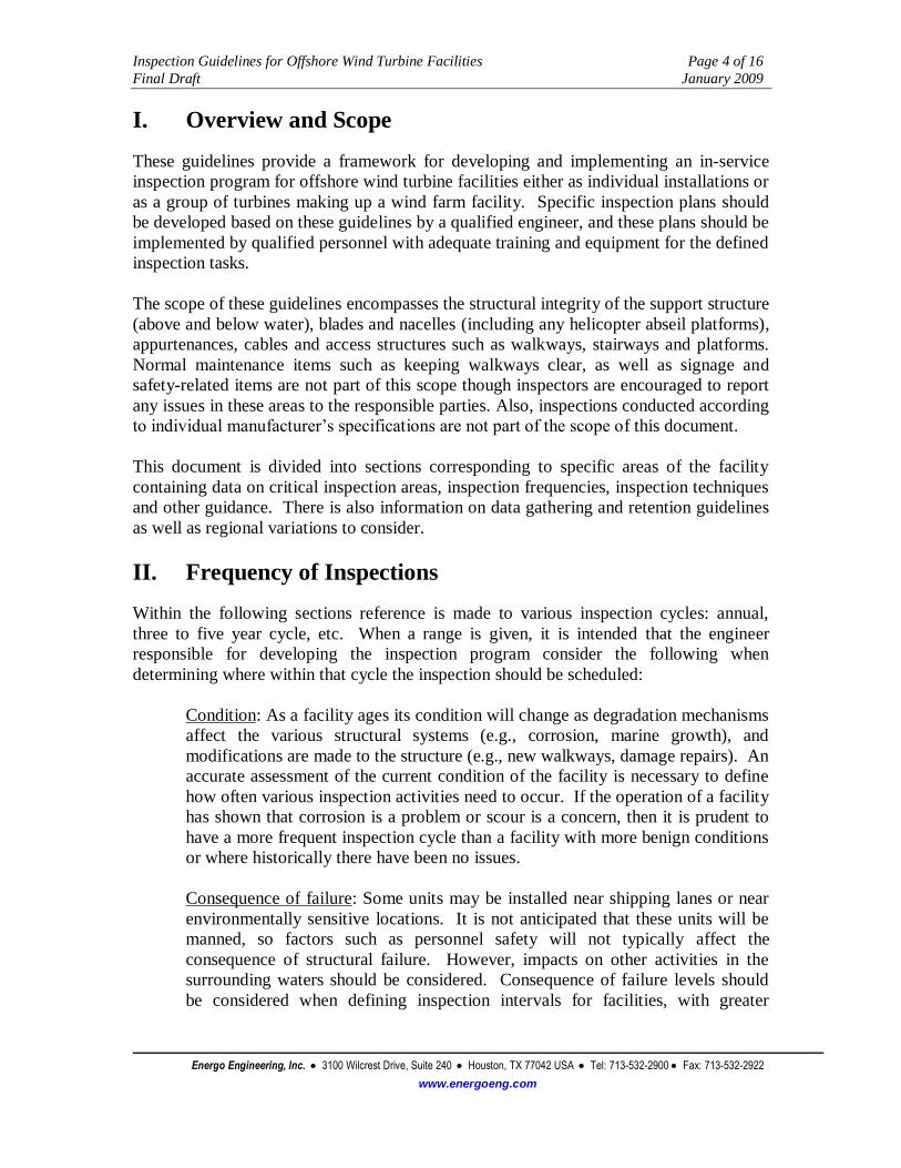
I. Overview and Scope
These guidelines provide a framework for developing and implementing an in-service
inspection program for offshore wind turbine facilities either as individual installations or
as a group of turbines making up a wind farm facility. Specific inspection plans should
be developed based on these guidelines by a qualified engineer, and these plans should be
implemented by qualified personnel with adequate training and equipment for the defined
inspection tasks.
The scope of these guidelines encompasses the structural integrity of the support structure
(above and below water), blades and nacelles (including any helicopter abseil platforms),
appurtenances, cables and access structures such as walkways, stairways and platforms.
Normal maintenance items such as keeping walkways clear, as well as signage and
safety-related items are not part of this scope though inspectors are encouraged to report
any issues in these areas to the responsible parties. Also, inspections conducted according
to individual manufacturer’s specifications are not part of the scope of this document.
This document is divided into sections corresponding to specific areas of the facility
containing data on critical inspection areas, inspection frequencies, inspection techniques
and other guidance. There is also information on data gathering and retention guidelines
as well as regional variations to consider.
II. Frequency of Inspections
Within the following sections reference is made to various inspection cycles: annual,
three to five year cycle, etc. When a range is given, it is intended that the engineer
responsible for developing the inspection program consider the following when
determining where within that cycle the inspection should be scheduled:
Condition: As a facility ages its condition will change as degradation mechanisms
affect the various structural systems (e.g., corrosion, marine growth), and
modifications are made to the structure (e.g., new walkways, damage repairs). An
accurate assessment of the current condition of the facility is necessary to define
how often various inspection activities need to occur. If the operation of a facility
has shown that corrosion is a problem or scour is a concern, then it is prudent to
have a more frequent inspection cycle than a facility with more benign conditions
or where historically there have been no issues.
Consequence of failure: Some units may be installed near shipping lanes or near
environmentally sensitive locations. It is not anticipated that these units will be
manned, so factors such as personnel safety will not typically affect the
consequence of structural failure. However, impacts on other activities in the
surrounding waters should be considered. Consequence of failure levels should
be considered when defining inspection intervals for facilities, with greater
Inspection Guidelines for Offshore Wind Turbine Facilities Page 5 of 16
Final Draft January 2009
Energo Engineering, Inc. 3100 Wilcrest Drive, Suite 240 Houston, TX 77042 USA Tel: 713-532-2900 Fax: 713-532-2922
www.energoeng.com
frequency of inspection given to those facilities with higher consequence of
failure.
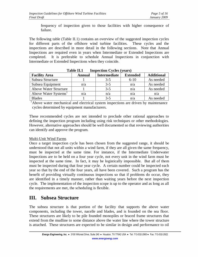
The following table (Table II.1) contains an overview of the suggested inspection cycles
for different parts of the offshore wind turbine facilities. These cycles and the
inspections are described in more detail in the following sections. Note that Annual
Inspections are required even in years when Intermediate or Extended Inspections are
completed. It is preferable to schedule Annual Inspections in conjunction with
Intermediate or Extended Inspections when they coincide.
Table II.1 Inspection Cycles (years)
Facility Area Annual Intermediate Extended Additional
Subsea Structure 1 3-5 6-10 As needed
Subsea Equipment n/a 3-5 n/a As needed
Above Water Structure 1 3-5 n/a As needed
Above Water Systems1 n/a n/a n/a n/a
Blades 1 3-5 n/a As needed 1 Above water mechanical and electrical system inspections are driven by maintenance
cycles determined by equipment manufacturers.
These recommended cycles are not intended to preclude other rational approaches to
defining the inspection program including using risk techniques or other methodologies.
However, alternative approaches should be well documented so that reviewing authorities
can identify and approve the program.
Multi-Unit Wind Farms
Once a target inspection cycle has been chosen from the suggested range, it should be
understood that not all units within a wind farm, if they are all given the same frequency,
must be inspected at the same time. For instance, if the Intermediate Underwater
Inspections are to be held on a four year cycle, not every unit in the wind farm must be
inspected at the same time. In fact, it may be logistically impossible. But all of them
must be inspected during that four year cycle. A certain number could be inspected each
year so that by the end of the four years, all have been covered. Such a program has the
benefit of providing virtually continuous inspections so that if problems do occur, they
are identified in a timely manner, rather than waiting years before the next inspection
cycle. The implementation of the inspection scope is up to the operator and as long as all
the requirements are met, the scheduling is flexible.
III. Subsea Structure
The subsea structure is that portion of the facility that supports the above water
components, including the tower, nacelle and blades, and is founded on the sea floor.
These structures are likely to be pile founded monopiles or braced frame structures that
extend from the mudline to some distance above the water line where the tower structure
is attached. These structures are expected to be similar in design and performance to oil

Inspection Guidelines for Offshore Wind Turbine Facilities Page 6 of 16
Final Draft January 2009
Energo Engineering, Inc. 3100 Wilcrest Drive, Suite 240 Houston, TX 77042 USA Tel: 713-532-2900 Fax: 713-532-2922
www.energoeng.com
and gas platform structures. Useful references for inspections of subsea structures are the
API RP 2A document for steel structures and ISO 19903 for concrete structures.
a. Critical Inspection Areas
The following areas should receive primary attention when developing an
inspection program due to their importance to maintaining structural integrity:
Steel Substructures
Circumferential welds on monopiles
Welded connections on braced structures
Major vertical members (e.g., legs, braces)
Splash zone
Concrete Substructures
Splash zone
Construction joints
Penetrations
Embedded plates
All Substructures
Cathodic Protection (CP) systems
Areas of previous repair or damage
Seabed scour
Settlement/subsidence
b. Inspection Cycles
Annual Inspections:
CP measurement using drop cells from above water
Intermediate Inspections
This inspection cycle should be performed at a 3 to 5 year interval and
documented with a written report including video and photographs.
General visual underwater inspection (GVI)
This level of inspection includes a visual inspection performed by
divers or ROV to detect any of the following:
1. Corrosion
2. Damaged or missing members
3. Scour, seabed instability, exposed seabed cables within visual
range of diver or ROV
4. Cracks or indications at welded joints or circumferential welds
5. Cracks or spalling of concrete especially at joints, penetrations
and around embedded plates
6. Excessive marine growth
7. Damaged risers/cables attached to structure

Inspection Guidelines for Offshore Wind Turbine Facilities Page 7 of 16
Final Draft January 2009
Energo Engineering, Inc. 3100 Wilcrest Drive, Suite 240 Houston, TX 77042 USA Tel: 713-532-2900 Fax: 713-532-2922
www.energoeng.com
8. Damaged riser/cable clamps or attachment devices
9. Other anomalies
Extended Inspections
This inspection cycle should be performed at a 6 to 10 year interval (at twice
the interval chosen for the Intermediate Inspections) and documented with a
written report including video and photographs.
General visual underwater inspection (GVI) as described above for
Intermediate Inspections
Close visual underwater inspections (CVI)
This level of inspection includes a visual inspection from no further
than arm’s length of an area pre-selected by engineers (e.g., welded
joints of the underwater structure determined by analysis to be critical
to structural stability). The area to be inspected should be cleaned of
any marine growth so clear examination of the underlying material can
be made. Close visual inspection is primarily intended to detect:
1. Cracks, indications or pitting at welded joints or
circumferential welds
2. Deterioration of concrete surfaces (e.g., cracks, spalling)
3. Structure condition at area of interest
4. Other anomalies
Additional Inspections
When anomalous conditions are identified it may be necessary to expand the
inspection scope or implement techniques that are able to provide more
information for review of the extent of the anomaly. Of primary importance is
the adequate documentation of the anomaly before the inspection team is
demobilized. Photos, video, sketches and measurements of the anomalous
condition that can be made with the available equipment should be taken so
that proper response can be determined.
A qualified engineer should be consulted to determine the scope and
technique of the any additional inspections. Typical additional inspections,
which may require mobilization of specialized technicians, include:
Close visual underwater inspections (CVI), as described in the
Extended Inspections section, in the area of the anomaly and as
directed by a qualified engineer
Non-destructive testing (NDT) inspections such as magnetic particle
inspections (MPI), ultrasonic testing (UT), or other to determine crack
depth, material thickness or other data needed to evaluate the anomaly
These additional inspections should be thoroughly documented in a
written report with details gathered including video and photos.

Inspection Guidelines for Offshore Wind Turbine Facilities Page 8 of 16
Final Draft January 2009
Energo Engineering, Inc. 3100 Wilcrest Drive, Suite 240 Houston, TX 77042 USA Tel: 713-532-2900 Fax: 713-532-2922
www.energoeng.com
IV. Subsea Equipment
The subsea equipment includes non-structural items related to the operation of the
facility. This includes cables, risers and j-tubes to protect the cables, junction boxes,
other umbilicals and similar equipment that is located below the waterline. Typically
risers and cables are attached to the subsea structure through clamps or other devices.
Away from the structure they are buried though in some cases they may be stretched
along the sea floor without being buried.
a. Critical Inspection Areas
The following areas should receive primary attention when developing an
inspection program due to their importance to maintaining operability:
Risers/J-tubes and attachments to the substructure
Electrical and control cables within field
Electrical cables to shore
Connectors and junction boxes
Areas of previous repair or damage
b. Inspection Cycles
Intermediate Inspections
This inspection cycle should be performed at a 3 to 5 year interval and
documented with a written report including video and photographs.
General visual underwater inspection
This level of inspection includes a visual inspection performed by
divers, ROV, or other appropriate equipment (e.g., side-scan sonar) to
detect any of the following in the area directly adjacent to the facility,
and along the cable routes to shore and other facilities:
1. Exposed cables where cables should be buried
2. Long unsupported sections of cable (e.g., caused by scour,
anchor dragging, displaced J-tubes, etc.)
3. Damaged cables or other equipment (e.g., from anchor
dragging, impact, etc.)
4. Other anomalies
Note that accurate maps of the “as laid” cable routes should be
maintained by the operator in order to facilitate these inspections.
Additional Inspections
When anomalous conditions are identified it may be necessary to expand the
inspection scope or implement techniques that are able to provide more
information for review of the extent of the anomaly. Of primary importance is
the adequate documentation of the anomaly before the inspection team is
demobilized. Photos, video, sketches and measurements of the anomalous
condition that can be made with the available equipment should be taken so

Inspection Guidelines for Offshore Wind Turbine Facilities Page 9 of 16
Final Draft January 2009
Energo Engineering, Inc. 3100 Wilcrest Drive, Suite 240 Houston, TX 77042 USA Tel: 713-532-2900 Fax: 713-532-2922
www.energoeng.com
that proper response can be determined. A qualified engineer should be
consulted to determine the scope and technique of the additional inspection.
V. Above Water Structural and Access Systems
The above water structural and access systems include the tower structure mounted on
the subsea structure and supporting the nacelle and blades, the nacelle itself and
helicopter abseil platforms, lifting devices, walkways, access ladders and stairs,
boatlandings, swing ropes, etc. Depending on the design, some of the access systems may
be inside the tower structure and shielded from the elements.
a. Critical Inspection Areas
The following areas should receive primary attention when developing an
inspection program due to their importance to maintaining structural integrity:
Tower to substructure attachment (e.g., welds to monopole)
Access systems (e.g., ladders, walkways, boatlanding, swing ropes,
handrails, helipads, helicopter abseil platforms, etc.) and lifting systems
Nacelle structure integrity
Overall facility deflection (i.e., does the facility lean due to structural
deformation, differential settlement, or other causes)
Areas of previous repair or damage
b. Inspection Cycles Annual Inspections:
General visual inspection (GVI)
This level of inspection includes a visual inspection performed by
qualified personnel and documented with a written report including
video and photographs. It is permissible, where required by access
restrictions, to accomplish these inspections with binoculars or other
similar equipment if they can provide sufficient detail to identify the
following anomalies:
1. Corrosion or coating breakdown
2. Damaged or missing members
3. Cracks or indications at welded joints
4. Damaged risers/cables attached to structure
5. Loose bolts
6. Evidence of lateral deflection or lean
7. Other anomalies
Intermediate Inspections
This inspection cycle should be performed at a 3 to 5 year interval and
documented with a written report including video and photographs.

Inspection Guidelines for Offshore Wind Turbine Facilities Page 10 of 16
Final Draft January 2009
Energo Engineering, Inc. 3100 Wilcrest Drive, Suite 240 Houston, TX 77042 USA Tel: 713-532-2900 Fax: 713-532-2922
www.energoeng.com
Non-destructive testing (NDT) at the connection between the tower
structure and the substructure. The welds or bolts at this connection
must be examined to determine their integrity.
1. Where bolts are used, their proper tensioning shall be
determined using a torque wrench or similar device.
2. Where welds are used, appropriate NDT techniques (e.g.,
magnetic particle inspection (MPI), eddy current inspection,
etc.) shall be used at key areas as determined by a qualified
engineer to identify indications.
Additional Inspections
When anomalous conditions are identified it may be necessary to expand the
inspection scope or implement techniques that are able to provide more
information for review of the extent of the anomaly. Of primary importance is
the adequate documentation of the anomaly before the inspection team is
demobilized. Photos, video, sketches and measurements of the anomalous
condition that can be made with the available equipment should be taken so
that proper response can be determined.
A qualified engineer should be consulted to determine the scope and
technique of the additional inspection. Typical additional inspections include:
Close visual inspections (CVI) from at least arms length with cleaning
of the area as necessary with measurements of the anomaly and other
investigation as directed by a qualified engineer
NDT inspections such as MPI, UT, or other to determine crack depth,
material thickness or other data needed to evaluate the anomaly
These additional inspections should be thoroughly documented in a
written report with details gathered including video and photos.
VI. Above Water Electrical and Mechanical Systems
These systems, including turbines, electrical cabling, junction boxes, panels, transformers
and generators, hydraulic systems and control systems should be inspected and
maintained in accordance with manufacturer recommendations to ensure efficient and
safe operations.
It is recommended that these maintenance activities be coordinated with the inspections
defined in this document and, where possible, the same personnel should implement the
activities. Where the same personnel are used, qualifications for maintenance and
inspection activities must be demonstrated and special training to complete some of the
structural tasks may be necessary.
It is also recommended that use of remote monitoring systems be implemented to provide
regular feedback on equipment function to identify anomalous conditions without the
need to have maintenance crews on the facility.

Inspection Guidelines for Offshore Wind Turbine Facilities Page 11 of 16
Final Draft January 2009
Energo Engineering, Inc. 3100 Wilcrest Drive, Suite 240 Houston, TX 77042 USA Tel: 713-532-2900 Fax: 713-532-2922
www.energoeng.com
VII. Blades
Blade damage is difficult to identify with general visual inspection techniques even when
augmented with binoculars or similar equipment. Remote monitoring of blade
performance (e.g., through power performance data analysis) should be planned and
implemented by a qualified engineer to provide regular feedback on blade performance
and proactively identify potential blade issues.
a. Critical Inspection Areas
The following areas should receive primary attention when developing an
inspection program due to their importance to maintaining blade integrity:
Blade attachment bolts
Blade condition
Areas of previous repair or damage
b. Inspection Cycles
Annual Inspections:
General visual inspection (GVI) documented with a written report
including video and photographs
By necessity, general visual inspection of blade will be assisted by
binoculars or other equipment to provide sufficient detail to identify
the following anomalies:
1. Material degradation (e.g., fiber or matrix failure, de-
lamination, stress fracture, stiffness degradation, etc.)
2. Blade damage (e.g., impact, lightning, etc.)
3. Erosion particularly at leading edge
4. Corrosion at attachment points
5. Other anomalies
Where possible to access the blades from the nacelle, this vantage shall
be used to observe the entire blade remotely and as much of the blade
root exterior and interior as possible looking for the anomalies
identified above.
Intermediate Inspections
This inspection cycle should be performed at a 3 to 5 year interval and
documented with a written report including video and photographs.
Non-destructive testing of the connection bolts connecting the blades
to the turbine system is required.
Additional Inspections
When anomalous conditions are identified it may be necessary to expand the
inspection scope or implement techniques that are able to provide more
information for review of the extent of the anomaly. Of primary importance is
the adequate documentation of the anomaly before the inspection team is

Inspection Guidelines for Offshore Wind Turbine Facilities Page 12 of 16
Final Draft January 2009
Energo Engineering, Inc. 3100 Wilcrest Drive, Suite 240 Houston, TX 77042 USA Tel: 713-532-2900 Fax: 713-532-2922
www.energoeng.com
demobilized. Photos, video, sketches and measurements of the anomalous
condition that can be made with the available equipment should be taken so
that proper response can be determined. A qualified engineer should be
consulted to determine the scope and technique of the additional inspection,
keeping in mind the access and safety issues involved in getting personnel and
equipment close to the blades. Typical additional inspections include:
Close visual inspections (CVI) from no more than arm’s length of the
area as necessary with measurements of the anomaly and other
investigation as directed by a qualified engineer
Non-destructive testing (NDT) inspections suitable for identifying
damage to blade material
With respect to turbine blades, power performance data analysis may be used,
in addition to visual inspections, to identify potential blade anomalies.
Appropriate NDT techniques should be employed to further evaluate the
condition of the blade and the blade material if either of the following is true:
the anomalous visual or power performance results are not due to
anticipated blade wear, material buildup or other mechanism
considered in the design of the blades
the operator cannot demonstrate that the anomalous condition will not
result in a loss of structural integrity prior to the next scheduled
inspection cycle
Of particular importance to blade integrity is evaluation of the shear web
bonds, and the leading and trailing edge bonds.
VIII. Post-Event Inspections
It is prudent to plan in advance how to inspect a facility if it is subjected to extreme event
loads. For instance, in the Gulf of Mexico, the controlling loading on a facility is likely
to be a hurricane storm event. If, following a storm, it is determined that the wind and
wave levels were close to or above the design values, an inspection should be initiated to
proactively look for damage to the system. Such assessments have historically been
mandated by the MMS in the Gulf of Mexico after major storm events.
Depending on where the facility is installed, the controlling design event may vary.
While hurricanes dominate the gulf coast regions, earthquakes are more likely to control
west coast facilities. Whatever the controlling event, the post-event goal is the same,
identify damage from high load levels.
It is possible to pre-select the areas of most concern that should be focused on during
these post-event inspections. Areas of the structure with the highest loads from design
analysis are likely to be the first to experience loading above yield and will likely be the
first to present deformation damage after a high load event. Having these plans laid out
in advance will save time and allow for a more efficient inspection process in a
sometimes hectic post-event environment.

Inspection Guidelines for Offshore Wind Turbine Facilities Page 13 of 16
Final Draft January 2009
Energo Engineering, Inc. 3100 Wilcrest Drive, Suite 240 Houston, TX 77042 USA Tel: 713-532-2900 Fax: 713-532-2922
www.energoeng.com
In addition to structural inspections, cable routes should also be examined after design
events, especially in areas where design events may lead to cable damage such as from
anchor drags during hurricanes or at fault crossings after earthquakes, in order to identify
damage or anomalies that could affect power transmission.
It is also important to consider how to determine remotely whether or not the facility is
safe to board and if it is not, how to conduct adequate inspections to determine what can
be done to either make it safe to board or conduct inspections without boarding.
Experience in the Gulf of Mexico has shown that access systems such as boat landings
and ladders are prone to damage and are not always safe to use following a storm.
Alternative access may need to be arranged and planning for this in advance can save
time and allow for a safer inspection.
IX. Engineering Evaluation
It is vital that all inspections described in the previous sections should be documented in
a written report augmented with sketches, photos and videos. These reports should be
reviewed by a qualified engineer familiar with the inspection program and evaluated to
determine:
That the inspections were performed as planned and have been adequately
documented
That results of the inspection are incorporated into integrity management plans
and future inspection priorities and plans are updated as necessary with the latest
inspection results
Any anomalous conditions are dealt with in a timely manner including:
Cleared as-is with follow-up inspections scheduled as needed
Identified for further investigation either through additional inspections or
analysis to determine further action (e.g., repairs)
This ensures that the cycle of integrity management is maintained so that anomalies are
adequately addressed and future inspections are planned based on the information
gathered from previous inspections.
X. Data Requirements
The collection and use of data generated as a result of the inspection process is as
important to the long-term integrity management of a facility as the inspection process
itself. The responsible engineer planning and interpreting the inspection data requires
current information on the condition of the facility in order to rationally plan the
inspections and make decisions regarding adequate response to anomalous conditions
found during the inspections.

Inspection Guidelines for Offshore Wind Turbine Facilities Page 14 of 16
Final Draft January 2009
Energo Engineering, Inc. 3100 Wilcrest Drive, Suite 240 Houston, TX 77042 USA Tel: 713-532-2900 Fax: 713-532-2922
www.energoeng.com
There are various levels of sophistication in data management approaches. It is not the
role of this guideline to define what level is chosen by an operator. But some data
management methodology must be defined by the operator in order to track the
information on the condition of the facilities they manage. Currently in draft form, the
API RP 2-SIM document contains useful guidance (see Section 4.2, Data) on what data
should be maintained and what approach should be followed for managing that data.
Also, the ISO 19902 document, Section 23.2, contains information on data gathering and
evaluation as part of an integrity management program that is applicable here.
As a minimum, checklists (see Appendix A for examples) should be developed to track
inspection activities and results. These provide a useful means of both prompting the
inspector to gather the required information and a recording mechanism to ensure that the
data is reported back to the responsible engineer in a uniform and repeatable manner.
Appendix A also contains an example of a reporting chart that should be developed for
all units managed by an operator for submittal to the MMS on an annual basis. This is
similar to the OSTS report required to be submitted for oil and gas production facilities in
the Gulf of Mexico.
It is also important that inspection activities both above and below water be documented
with photographs and video. These are often invaluable references for allowing the
responsible engineer to evaluate the structure’s condition and any anomalies identified.
XI. Regional Variations
Different areas of the country will have different environmental factors affecting the
condition and operations of wind turbine facilities. These regional variations should be
considered when evaluating where and how to inspect different parts of the structure.
These variations go beyond loads that will dominate the design of the facilities (e.g.,
hurricanes in the Gulf of Mexico or earthquakes offshore California). The following list
provides some guidance on factors that could affect facilities in different regions but each
operator will need to evaluate how local factors impact condition and review their data to
determine dominant degradation mechanisms.
Northeast Region (Atlantic)
Low Temperatures with potential for icing, especially affecting blade
performance
Loading dominated by hurricane storms
Southeast Region (Atlantic)
More aggressive corrosion environment at higher temperatures and
humidity
Loading dominated by hurricane storms
Gulf of Mexico Region

Inspection Guidelines for Offshore Wind Turbine Facilities Page 15 of 16
Final Draft January 2009
Energo Engineering, Inc. 3100 Wilcrest Drive, Suite 240 Houston, TX 77042 USA Tel: 713-532-2900 Fax: 713-532-2922
www.energoeng.com
More aggressive corrosion environment at higher temperatures and
humidity
Loading dominated by hurricane storms
Northwest Region (Pacific)
Potentially higher fatigue damage in more demanding operational wave
environment
Loading dominated by earthquake events
Effect of tsunamis
Southwest Region (Pacific)
Potentially higher fatigue damage in more demanding operational wave
environment
Loading dominated by earthquake events
Effect of tsunamis
Alaska Region
Low Temperatures with potential for icing, especially affecting blade
performance
Loading dominated by earthquake events
Effect of tsunamis
Hawaii Region
More aggressive corrosion environment at higher temperatures and
humidity
Potentially higher fatigue damage in more demanding operational wave
environment
Loading dominated by hurricane storms
Effect of tsunamis
XII. Startup Inspections
Though these guidelines address in-service inspections it is recommended that an
inspection be performed of the facility prior to startup. Guidance for these inspections can
be found in ISO 19902, Section 21, covering topics such as inspection scope, inspection
methods, and documentation. The goal is to ensure that installation was performed
according to the standards set forth in the design documents and installation plan, and
that the facility is fit-for-purpose.

Inspection Guidelines for Offshore Wind Turbine Facilities Appendix A
Draft December 2008
Energo Engineering, Inc. 3100 Wilcrest Drive, Suite 240 Houston, TX 77042 USA Tel: 713-532-2900 Fax: 713-532-2922
www.energoeng.com
Appendix A
Sample Checklists and
Data Reporting
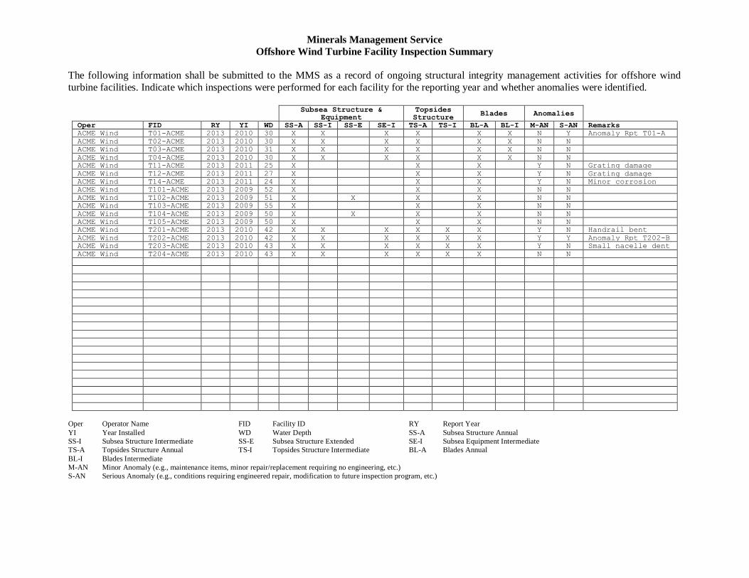
Minerals Management Service
Offshore Wind Turbine Facility Inspection Summary
The following information shall be submitted to the MMS as a record of ongoing structural integrity management activities for offshore wind
turbine facilities. Indicate which inspections were performed for each facility for the reporting year and whether anomalies were identified.
Subsea Structure &
Equipment Topsides Structure
Blades Anomalies
Oper FID RY YI WD SS-A SS-I SS-E SE-I TS-A TS-I BL-A BL-I M-AN S-AN Remarks
ACME Wind T01-ACME 2013 2010 30 X X X X X X N Y Anomaly Rpt T01-A
ACME Wind T02-ACME 2013 2010 30 X X X X X X N N
ACME Wind T03-ACME 2013 2010 31 X X X X X X N N
ACME Wind T04-ACME 2013 2010 30 X X X X X X N N
ACME Wind T11-ACME 2013 2011 25 X X X Y N Grating damage
ACME Wind T12-ACME 2013 2011 27 X X X Y N Grating damage
ACME Wind T14-ACME 2013 2011 24 X X X Y N Minor corrosion
ACME Wind T101-ACME 2013 2009 52 X X X N N
ACME Wind T102-ACME 2013 2009 51 X X X X N N
ACME Wind T103-ACME 2013 2009 55 X X X N N
ACME Wind T104-ACME 2013 2009 50 X X X X N N
ACME Wind T105-ACME 2013 2009 50 X X X N N
ACME Wind T201-ACME 2013 2010 42 X X X X X X Y N Handrail bent
ACME Wind T202-ACME 2013 2010 42 X X X X X X Y Y Anomaly Rpt T202-B
ACME Wind T203-ACME 2013 2010 43 X X X X X X Y N Small nacelle dent
ACME Wind T204-ACME 2013 2010 43 X X X X X X N N
Oper Operator Name FID Facility ID RY Report Year
YI Year Installed WD Water Depth SS-A Subsea Structure Annual
SS-I Subsea Structure Intermediate SS-E Subsea Structure Extended SE-I Subsea Equipment Intermediate
TS-A Topsides Structure Annual TS-I Topsides Structure Intermediate BL-A Blades Annual
BL-I Blades Intermediate
M-AN Minor Anomaly (e.g., maintenance items, minor repair/replacement requiring no engineering, etc.)
S-AN Serious Anomaly (e.g., conditions requiring engineered repair, modification to future inspection program, etc.)

Minerals Management Service
Offshore Wind Turbine Facility Annual Inspections Checklist
Note: This checklist is not a substitute for an integrity management program and data recording system
for offshore wind turbine facilities. It is a data summary requested by the MMS.
Operator: _______________________________ Facility ID: _______________________________
Report Year: ____________________________ Year Installed/Water Depth __________________
SAFETY / SIGNAGE / MARKINGS Indicate Yes or No to each item and whether or not Corrective Action (CA) was taken
No. Item Y N CA
1. Are walkways, ladders, handrails, stairs and other access systems in
good working condition?
2. Are warning/safety/instructional signs visible and legible?
3. Are markings showing facility identification, water level markings,
etc. visible and legible
4. Are there obstructions to egress paths (e.g., equipment stored on stairs)?
5. Are fall protection anchorage points in good condition?
6. Are navigation and aviation warning lights operational?
7. Are fire protection systems operational?
8. Are there other anomalies noted?
SUBSEA CATHODIC PROTECTION
Indicate Yes or No to each item and whether or not Corrective Action (CA) was taken
No. Item Y N CA
1. Are CP measurements within acceptable range?
2. Are there other anomalies noted?
TOPSIDES STRUCTURE INSPECTIONS Indicate Yes or No to each item and whether or not Corrective Action (CA) was taken
No. Item Y N CA
1. Are there any signs of coating breakdown and/or corrosion?
2. Are there any signs of physical damage including dents, holes or other deformation to structural members or nacelle housing?
3. Are there any cracks or visible indications at welded connections?
4. At bolted connections are nuts noticeably loose?
5. Are cables and risers, and their attachments in good condition?
6. Are there other anomalies noted?
BLADE INSPECTIONS
Indicate Yes or No to each item and whether or not Corrective Action (CA) was taken
No. Item Y N CA
1. Is there any sign of blade material degradation (e.g., de-lamination)?
2. Are there signs of blade damage or erosion?
3. Are there signs of corrosion especially at the blade attachment points?
4. Are there other anomalies noted?