Danfoss Drives - VLT · correct manual is being printed and made ... tion and service, Danfoss...
40
Danfoss Drives VLT® Product Catalogue
Transcript of Danfoss Drives - VLT · correct manual is being printed and made ... tion and service, Danfoss...
Danfoss DrivesVLT® Product Catalogue

2
The leading provider of Drives
The developers at Danfoss Drives have
fully adopted modular principles in
development as well as design, produc-
tion and confi guration. Each function is
developed in parallel on dedicated
technology platforms and interfaces
between the elements are carefully
defi ned. This allows development to take
place for each element in parallel,
reducing time to market and ensuring
that customers always enjoy the benefi ts
of recently developed features.
This unique modular concept is also the
basis for a highly automated quality
manufacturing process, where Danfoss
Drives takes responsibility for every
element – starting with the essential semi
conductor power modules. Power
Modules are produced in Danfoss Silicon
Power in Schleswig, Germany. High quality
standards and effi cient manufacturing
facilities makes Danfoss Silicon Power
modules in great demand within indus-
tries that provide highly automated
power-applications like the automotive
sector.
Two thousand employees headed from
Graasten in Denmark develop, manu-
facture, sell and service electronic motor
controls in more than one hundred
countries.
Manufacturing takes place in USA –
Especially the high power products –and
in Asia, but the major production takes
place in the plants in Graasten, Denmark,
where half of the staff are employed.
Danfoss Bauer geared motors are
manufactured in Esslingen, Germany.
The success of Danfoss is due to the
strong combination of technology and
application knowledge throughout the
world combined with a highly sophisti-
cated set-up of product development,
supply chain, logistics and on-site
presence anywhere on the globe.
Our customers are closely involved during
every stage of design and development,
specifying their needs in terms of features
and user interface. Danfoss Drives
dedicates itself to every step in every
process until the customer has the drive in
hand.
When it comes to quality, delivery and
cooperation, Danfoss makes high
demands on their suppliers – both from
inside and outside of the group.
Due to an unsurpassed level of auto-
mation Danfoss can produce a customer
confi gured drive from 1.6 million possible
confi gurations in a manu facturing time of
two hours. The unique string type code
that fully defi nes the drive can easily be
obtained throughout the world by use of
the internet; it determines the confi gura-
tion of all elements of the drive, both
electronics and hardware. Once this
unique confi guration is passed to the
production departments the manufactur-
ing process can begin. Testing is carried
out at all stages of the process and begins
with optical checks of the PCBs to ensure
that components are inserted correctly.
Once the PCBs are fully assembled they all
must pass an automatic in-circuit test.
After assembly is complete all drives are
fully tested on motor loads.
During the drives manufacturing cycle the
correct manual is being printed and made
avaiable for packing. By the use of this
process we ensure that not only the
correct language but the very latest
version of the manual is always produced
and shipped with the correct drive. Just in
time delivery is a reality.
Once the drive is shipped, one of more
than 60 local Danfoss sales companies can
ensure that the drive is correctly installed
and commissioned. Once the equipment
is commis sioned, the level of service the
customer requires can be defi ned in an
agreement with the customer according
to his specifi c needs. At every step of the
way, from development of new technolo-
gies and features, the mass production of
highly customised products, to installa-
tion and service, Danfoss Drives has only
the customer in mind.

Contents
3
VLT® AutomationDrive
The VLT® AutomationDrive represents a single drive concept to control the entire range of operations from standard to servo on any machine or production line.
Page 8
VLT® 2800 Series
An extremely compact series of drives prepared for side-by-side mounting and developed specifically for the low power market.
Page 6
VLT® Micro Drive
The VLT® Micro Drive is a general purpose drive that can control AC motors up to 7.5 kW. It’s a small drive with maximum strength and reliability.
Page 4
VLT® HVAC Drive
The VLT ® HVAC Drive integrates and communi-cates seamlessly with all HVAC devices, mastered by Building Management Systems or as stand-alone unit.
Page 14
VLT® 5000
The perfect match for an abundance of industrial applications.
Page 10
VLT® 5000 Flux
The VLT® 5000 Flux is an extension of the existing VLT® 5000 series. Full torque control also under acceleration as well as very accurate speed control even at low speed or standstill can now be obtained.
Page 12
VLT® 6000 HVAC
The VLT® 6000 HVAC is fully dedicatedto the optimum operation of HVACapplications. It off ers energy savingsand user-friendliness, and all functionsare built in.
Page 16
VLT® AQUA Drive
VLT® AQUA Drive the perfect match for pumps and blowers in modern water and wastewater systems.
Page 18
VLT® Decentral FCD 300
The VLT® Decentral FCD 300 is a complete frequency converter designed for decentral mounting.
Page 24
VLT® High Power Drives
VLT® series high power drives reduce energy usage in driven equipment. High efficiency of the VLT® series also drives down energy costs in cooling requirements.
Page 22
VLT® 8000 AQUA
The VLT® 8000 has been designed to operate in the water and wastewater market.
Page 20
VLT® Compact Starter MCD 200
The MCD 200 is a compact and cost eff ective soft starter range for applications where direct-on-line starting is undesirable. MCD 200 is due to its size and functionality a good alternative to other reduced voltage starting methods such as start/delta starters.
Page 30
VLT® DriveMotor FCM 300
The VLT ® FCM 300 Series is a very compact alternative to the traditional solution with a VLT® frequency converter and motor as separate units.
Page 26
VLT® Soft Starter MCD 100
The VLT® Soft Starter MCD 100 provides soft start features for low power applications 1.1 – 11 kW.
Page 28
VLT® Soft Starter MCD 3000
The MCD 3000 is a total motor starter providing all the best in soft starter func tionality. It off ers high end functionality whether it is for starting, stopping or protection of motor or application.
Page 32
VLT® Harmonic Filter AHF 005/010
Connecting the AHF 005/010 harmonic fi lter in front of a Danfoss frequency converter is an easy and eff ective way to reduce harmonic distortion.
Page 34

VLT® Micro Drive
The VLT® Micro Drive is a general
purpose drive that can control
AC motors up to 7.5 kW. It’s a small
drive with maximum strength and
reliability.
RoHS compliant
The VLT® Micro Drive is manufactured
with respect for the environment, and
it complies with the RoHS Directive.
The perfect match for:
• Industrial appliances
• HVAC applications
• OEM
Power range:
1 phase 200–240 V AC .......0.18–2.2 kW
3 phase 200–240 V AC .......0.25–3.7 kW
3 phase 380–480 V AC .......0.37–7.5 kW
Coated PCB standard
For harsh environments.
4
Mount Connect ...and the motor is running
Specifi cations
5
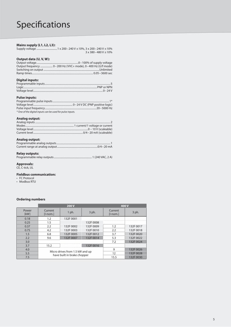
Mains supply (L1, L2, L3): Supply voltage ................................1 x 200–240 V ±10%, 3 x 200–240 V ±10% 3 x 380–480 V ±10%
Output data (U, V, W):Output voltage. ................................................................0–100% of supply voltageOutput frequency ................... 0–200 Hz (VVC+ mode), 0–400 Hz (U/f mode)Switching on output .......................................................................................UnlimitedRamp times ............................................................................................... 0.05–3600 sec
Digital inputs:Programmable inputs ......................................................................................................5Logic ..................................................................................................................PNP or NPNVoltage level ............................................................................................................ 0–24 V
Pulse inputs:Programmable pulse inputs ........................................................................................1*Voltage level ............................................................. 0–24 V DC (PNP positive logic)Pulse input frequency ................................................................................20–5000 Hz* One of the digital inputs can be used for pulse inputs.
Analog output:Analog inputs .....................................................................................................................2Modes ........................................................................... 1 current/1 voltage or currentVoltage level .....................................................................................0 – 10 V (scaleable)Current level ............................................................................. 0/4–20 mA (scaleable)
Analog output:Programmable analog outputs ....................................................................................1Current range at analog output ...............................................................0/4–20 mA
Relay outputs:Programmable relay outputs ........................................................... 1 (240 VAC, 2 A)
Approvals:CE, C-tick, UL
Fieldbus communication:• FC Protocol• Modbus RTU
200 V 400 V
Power [kW]
Current [I-nom.]
1 ph. 3 ph.Current [I-nom.]
3 ph.
0.18 1.2 132F 0001
0.25 1.5 132F 0008
0.37 2.2 132F 0002 132F 0009 1.2 132F 0017
0.75 4.2 132F 0003 132F 0010 2.2 132F 0018
1.5 6.8 132F 0005 132F 0012 3.7 132F 0020
2.2 9.6 132F 0007 132F 0014 5.3 132F 0022
3.0 7.2 132F 0024
3.7 15.2 132F 0016
4.0Micro drives from 1.5 kW and up
have built in brake chopper
9 132F 0026
5.5 12 132F 0028
7.5 15.5 132F 0030
Ordering numbers
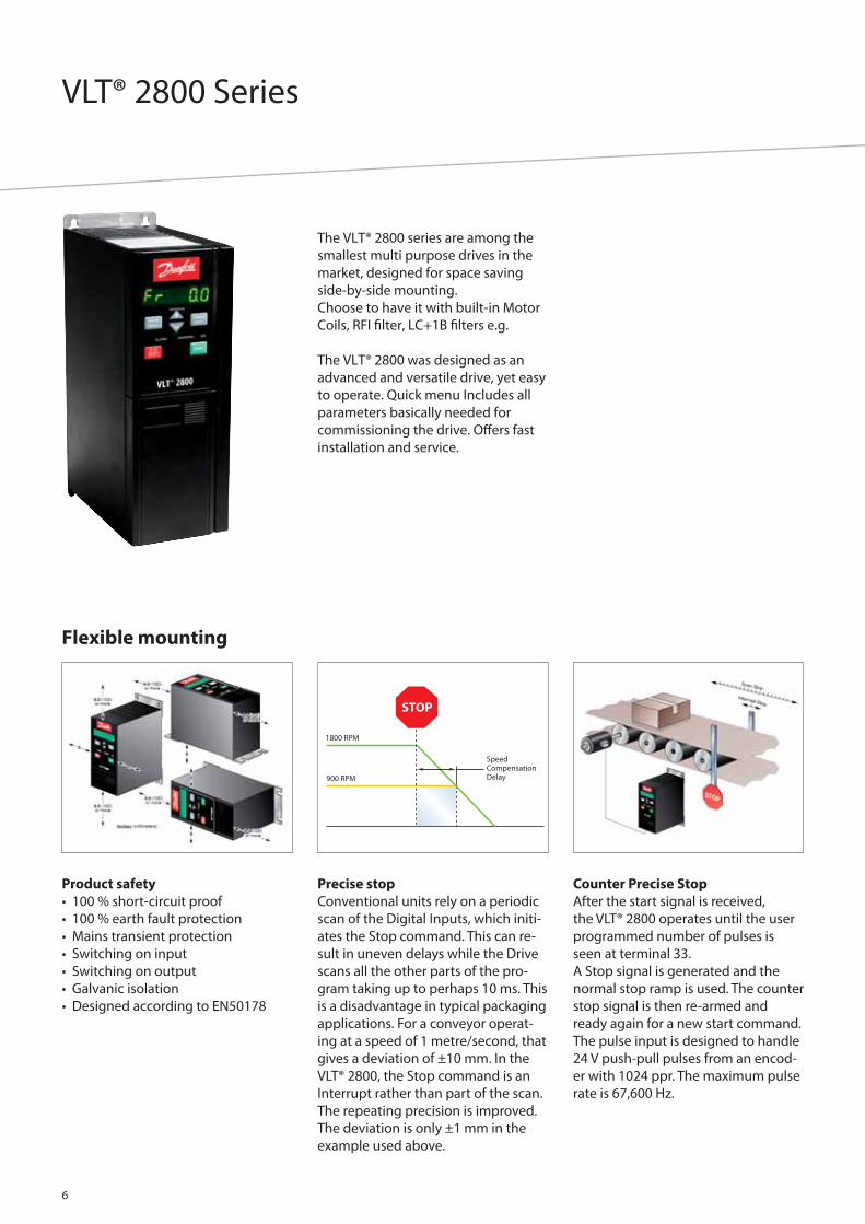
VLT® 2800 Series
The VLT® 2800 series are among the
smallest multi purpose drives in the
market, designed for space saving
side-by-side mounting.
Choose to have it with built-in Motor
Coils, RFI fi lter, LC+1B fi lters e.g.
The VLT® 2800 was designed as an
advanced and versatile drive, yet easy
to operate. Quick menu Includes all
parameters basically needed for
commissioning the drive. Off ers fast
installation and service.
Precise stop
Conventional units rely on a periodic
scan of the Digital Inputs, which initi-
ates the Stop command. This can re-
sult in uneven delays while the Drive
scans all the other parts of the pro-
gram taking up to perhaps 10 ms. This
is a disadvantage in typical packaging
applications. For a conveyor operat-
ing at a speed of 1 metre/second, that
gives a deviation of ±10 mm. In the
VLT® 2800, the Stop command is an
Interrupt rather than part of the scan.
The repeating precision is improved.
The deviation is only ±1 mm in the
example used above.
Counter Precise Stop
After the start signal is received,
the VLT® 2800 operates until the user
programmed number of pulses is
seen at terminal 33.
A Stop signal is generated and the
normal stop ramp is used. The counter
stop signal is then re-armed and
ready again for a new start command.
The pulse input is designed to handle
24 V push-pull pulses from an encod-
er with 1024 ppr. The maximum pulse
rate is 67,600 Hz.
Product safety
• 100 % short-circuit proof
• 100 % earth fault protection
• Mains transient protection
• Switching on input
• Switching on output
• Galvanic isolation
• Designed according to EN50178
Flexible mounting
6

Specifi cations
7
Mains supply (L1, L2, L3): Supply voltage: VLT 2803-2815 220-240 V (N, L1) ....................................1 x 220/230/240 V ±10%VLT 2803-2840 200-240 V ...............................3 x 200/208/220/230/240 V ±10%VLT 2805-2882 380-480 V ...............................3 x 380/400/415/440/480 V ±10%Supply frequency ................................................................................50/60 Hz ± 3 HzMax. imbalance on supply voltage .................. ± 2.0% of rated supply voltageTrue Power Factor (λ) ......................................................0.90 nominal at rated loadDisplacement Power Factor (cosф) ...........................................near unity (> 0.98)Number of connections at supply input L1, L2, L3 ........................ 2 times/min.Max. short-circuit value. .................................................................................100,000 A
Output data (U, V, W):Output voltage. ...............................................................0 – 100% of supply voltageOutput frequency .............................................................. 0.2 – 132 Hz, 1 – 1000 HzRated motor voltage, 200-240 V units ......................... 200/208/220/230/240 VRated motor voltage, 380-480 V units ................380/400/415/440/460/480 VRated motor frequency ....................................................................................50/60 HzSwitching on output. ......................................................................................UnlimitedRamp times ............................................................................................. 0.02 – 3600 sec.
Torque characteristics:Starting torque Constant torque) ...................................................160% in 1 min.*Starting torque (Variable torque) ..................................................160% in 1 min.*Starting torque (parameter 119 High starting torque ) ...... 180% for 0.5 sec.*Overload torque (Constant torque) ................................................................ 160%*Overload torque (Variable torque) .................................................................. 160%**Percentage relates to frequency converter’s nominal current.
Control card, digital inputs:Number of programmable digital inputs .................................................................5Terminal number .................................................................................18, 19, 27, 29, 33Voltage level. ........................................................... 0 – 24 V DC (PNP positive logic)Voltage level, logic ’0’ ........................................................................................< 5 V DCVoltage level, logic ’1’ .....................................................................................> 10 V DCMaximum voltage on input .............................................................................28 V DCInput resistance, Ri (terminals 18, 19, 27, 29) ................................... approx. 4 kΩInput resistance, Ri (terminal 33) .......................................................... approx. 2 kΩAll digital inputs are galvanically isolated from the supply voltage (PELV) and other high-voltage terminals.
Control card, analog inputs:Number of analog voltage inputs ...............................................................................1Terminal number .............................................................................................................53Voltage level. .............................................................................0 – 10 V DC (scaleable)Input resistance, Ri . .................................................................................approx. 10 kΩMax. voltage ..................................................................................................................20 VNumber of analog current inputs ................................................................................1Terminal number ............................................................................................................ 60Current level ............................................................................0/4 – 20 mA (scaleable)Input resistance, Ri ................................................................................. approx. 300 ΩMax. current ..............................................................................................................30 mAResolution for analog inputs ............................................................................... .10 bitAccuracy of analog inputs ............................................. Max. error 1% of full scaleScan interval. ......................................................................................................13.3 msecThe analog inputs are galvanically isolated from the supply voltage (PELV) and other high-voltage terminals.
Control card, pulse inputs:Number of programmable pulse inputs ...................................................................1Terminal number .............................................................................................................33Max. frequency at terminal 33 ................................................67.6 kHz (Push-pull)Max. frequency at terminal 33 ............................................5 kHz (open collector)Min. frequency at terminal 33 ............................................................................... 4 HzVoltage level. .......................................................... 0 – 24 V DC (PNP positive logic)Voltage level, logic ’0’ ........................................................................................< 5 V DCVoltage level, logic ’1’ .....................................................................................> 10 V DCMaximum voltage on input ..............................................................................28 V DCInput resistance, Ri ..................................................................................... approx. 2 kΩScan interval .......................................................................................................13.3 msecResolution ...................................................................................................................10 bitAccuracy (100 Hz – 1 kHz) terminal 33 ................ Max. error: 0.5% of full scaleAccuracy (1 kHz – 67.6 kHz) terminal 33 ..............Max. error: 0.1% of full scaleThe pulse input (terminal 33) is galvanically isolated from the supply voltage (PELV) and other high-voltage terminals.
Control card, digital/frequency output:Number of programmable digital/pulse outputs ........................................ 1 pcs.Terminal number .............................................................................................................46Voltage level at digital/frequency output ........................0 – 24 V DC (O.C PNP)Max. output current at digital/frequency output ........................................25 mAMax. load at digital/frequency output............................................................... 1 kΩMax. capacity at frequency output .................................................................... 10 nFMinimum output frequency at frequency output ...................................... 16 HzMaximum output frequency at frequency output .....................................10 kHzAccuracy on frequency output ................................Max. error: 0.2% of full scaleResolution on frequency output ....................................................................... 10 bitThe digital output is galvanically isolated from the supply voltage (PELV) and other high-voltage terminals.
Control card, analog output:Number of programmable analog outputs . ...........................................................1Terminal number .............................................................................................................42Current range at analog output ............................................................. 0/4 – 20 mAMax. load to common at analog output ..........................................................500 ΩAccuracy on analog output ......................................Max. error: 1.5% of full scaleResolution on analog output ...............................................................................10 bitThe analog output is galvanically isolated from the supply voltage (PELV) and other high-voltage terminals.
Control card, 24 V DC output:Terminal number .............................................................................................................12Max. load . ...............................................................................................................130 mAThe 24 V DC supply is galvanically isolated from the supply voltage (PELV), but has the same potential as the analogue and digital inputs and outputs.
Control card, 10 V DC output:Terminal number .............................................................................................................50Output voltage ........................................................................................... 10.5 V ± 0.5 VMax. load ....................................................................................................................15 mAThe 10 V DC supply is galvanically isolated from the supply voltage (PELV) and other high-voltage terminals.
Control card, RS 485 serial communication:Terminal number ............................................................68 (TX+, RX+), 69 (TX-, RX-)Terminal number 67 ..................................................................................................+ 5 VTerminal number 70 ...................................Common for terminals 67, 68 and 69Full galvanic isolation.
Relay outputs:Number of programmable relay outputs .................................................................1Terminal number, control card ...........................................1-3 (break), 1-2 (make)Max. terminal load (AC) on 1-3, 1-2, control card .......................... 240 V AC, 2 AMin. terminal load on 1-3, 1-2, control card 24 V DC 10 mA, 24 V AC 100 mAThe relay contact is separated from the rest of the circuit by strengthened isolation.
Cable lengths and cross sections:Max. motor cable length:Screened/armoured cable ..................................................................................... 40 mUnscreened/unarmoured cable ........................................................................... 75 mScreened/armoured cable and motor coil. ....................................................100 mUnscreened/unarmoured cable and motor coil ..........................................200 mScreened/armoured cable and RFI/1B fi lter ..................................... 200 V, 100 mScreened/armoured cable and RFI/1B or RFI 1B/LC fi lter .............. 400 V, 25 mMax. cross section to control wires, rigid wire .................................................................1.5 mm2/16 AWG (2 x 0.75 mm2)Max. cross section to control cables, fl exible cable ...........................................................................................1 mm2/18 AWGMax. cross section to control cables, cable with enclosed core ................................................................ 0.5 mm2/20 AWGWhen complying with EN 55011 1A and EN 55011 1B the motor cable must in certain instances be reduced.

8
VLT® AutomationDrive
The VLT® AutomationDrive FC 300 is
extremely confi gurable and runs any
motor in any application and any
machine for manufacturing.
Specify your requirements and have
your drives tailor-made within a
couple of hours – for the cost of mass
produced stockware.
Range:
0.25 – 37 kW ........................ (200 – 240 V)
0.75 – 1000 kW ................... (525 – 600 V)
11 – 1000 kW ....................... (600 – 690 V)
One-Drive concept
One-Drive concept covering the
whole production or machine is a
major benefi t in commissioning,
operating and maintaining the
equipment. The make-through
modular design makes upgrade easy
as well as adaptation of future
features. On-board manuals make
operation easy and the built in Smart
Logic Control allows for basic pro-
gramming covering many common
PLC functions.
Pluggable options
The bus option, as shown above,
ready to plug in underneath the front
panel. It can be turned upside down
if you prefer the cable to enter from
the top.
USB pluggable
The VLT® AutomationDrive can be
remotely commissioned and moni-
tored through a USB pluggable cable
or bus communication. Special
software is available: Wizards, Data
transfer tool, VLT® Set-up Software
MCT 10.
Remote commissioning
Local control of the VLT® Automation-
Drive is done by a local control panel.
This is plugged in directly or con-
nected through a cable.
Plug and play
You don’t have to disconnect wires in
the cage clamps to disconnect the
VLT® AutomationDrive. Just unplug
the cage clamp instead.
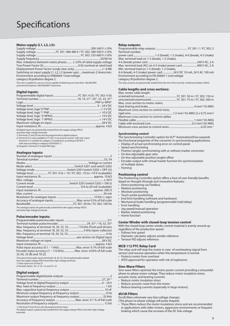
Specifi cations
9
Mains supply (L1, L2, L3):Supply voltage .....................................................................................200-240 V ±10%Supply voltage ..............................FC 301: 380-480 V / FC 302: 380-500 V ±10%Supply voltage ..................................................................... FC 302: 525-600 V ±10%Supply frequency ...............................................................................................50/60 HzMax. imbalance between mains phases ........ ± 3.0% of rated supply voltageTrue Power Factor (λ) ......................................................0.92 nominal at rated loadDisplacement Power Factor (cosф) near unity. .......................................... (> 0.98)Switching on input supply L1, L2, L3 (power-ups) ....maximum 2 times/min.Environment according to EN60664-1overvoltage category III/pollution degree 2. The unit is suitable for use on a circuit capable of delivering not more than 100.000 RMS symmetrical Amperes, 240/500/600 V maximum.
Digital inputs:Programmable digital inputs ......................................FC 301: 4 (5) / FC 302: 4 (6)Terminal number ............................................................18, 19, 271), 291), 32, 33, 372)
Logic ................................................................................................................PNP or NPN3)
Voltage level ................................................................................................... 0 – 24 V DCVoltage level, logic’0’ PNP.................................................................................< 5 V DCVoltage level, logic’1’ PNP..............................................................................> 10 V DCVoltage level, logic ’0’ NPN3) ........................................................................> 19 V DCVoltage level, logic ’1’ NPN3) ........................................................................< 14 V DCMaximum voltage on input ..............................................................................28 V DCInput resistance, Ri ..................................................................................... approx. 4 kΩAll digital inputs are galvanically isolated from the supply voltage (PELV) and other high-voltage terminals. 1) Terminals 27 and 29 can also be programmed as digital outputs.2) Terminal 37 is only available in FC 302. It can only be used as “safe stop” input.
Terminal 37 is suitable for category 3 installations according to EN 954-1 (safe stop according to category 0 EN 60204-1).
3) Exception: Terminal 37 is fi xed PNP logic.
Analogue inputs:Number of analogue inputs .........................................................................................2Terminal number ......................................................................................................53, 54Modes .................................................................................................. Voltage or currentMode select ..................................................................Switch S201 and switch S202Voltage mode ..................................................Switch S201/switch S202 = OFF (U)Voltage level ....................... FC 301: 0 to + 10 / FC 302: -10 to +10 V (scaleable)Input resistance, Ri .................................................................................. approx. 10 kΩMax. voltage .............................................................................................................. ± 20 VCurrent mode ..................................................... Switch S201/switch S202 = ON (I)Current level ......................................................................... 0/4 to 20 mA (scaleable)Input resistance, Ri .................................................................................. approx. 200 ΩMax. current ..............................................................................................................30 mAResolution for analogue inputs . .........................................................10 bit (+ sign)Accuracy of analogue inputs.....................................Max. error 0.5% of full scaleBandwidth...................................................................FC 301: 20 Hz / FC 302: 100 HzThe analogue inputs are galvanically isolated from the supply voltage (PELV)and other high-voltage terminals.
Pulse/encoder inputs:Programmable pulse/encoder inputs ...................................................................2/1Terminal number pulse/encoder. ........................................... 29, 331) / 18, 32, 332)
Max. frequency at terminal 18, 29, 32, 33 ...............110 kHz (Push-pull driven)Max. frequency at terminal 18, 29, 32, 33 ........................5 kHz (open collector)Min. frequency at terminal 18, 29, 32, 33. ...........................................................4 HzVoltage level ....................................................................see section on Digital inputMaximum voltage on input ..............................................................................28 V DCInput resistance, Ri ..................................................................................... approx. 4 kΩPulse input accuracy (0.1 – 1 kHz) ..........................Max. error: 0.1% of full scaleEncoder input accuracy (1 – 110 kHz) ................ Max. error: 0.05% of full scale32 (A), 33 (B) and 18 (Z)The pulse and encoder inputs (terminals 18, 29, 32, 33) are galvanically isolated from the supply voltage (PELV) and other high-voltage terminals. 1) Pulse inputs are 29 and 332) Encoder inputs: 18 = Z, 32 = A, and 33 = B
Digital output:Programmable digital/pulse outputs ........................................................................2Terminal number .................................................................................................. 27, 29 1)
Voltage level at digital/frequency output ..................................................0 – 24 VMax. load at frequency output .............................................................................. 1 kΩMax. capacitive load at frequency output ...................................................... 10 nFMinimum output frequency at frequency output ..........................................0 HzMaximum output frequency at frequency output .....................................32 kHzAccuracy of frequency output . ..............................Max. error: 0.1 % of full scaleResolution of frequency outputs ........................................................................12 bit1) Terminal 27 and 29 can also be programmed as input.The digital output is galvanically isolated from the supply voltage (PELV) and other high-voltage terminals.
Relay outputs:Programmable relay outputs .................................................. FC 301: 1 / FC 302: 2Terminal number, power card. .................................1-3 (break), 1-2 (make), 4-6 (break), 4-5 (make)Max. terminal load on 1-3 (break), 1-2 (make), 4-6 (break) power card ............................................................................ 240 V AC, 2 AMax. terminal load (AC) on 4-5 (make) power card ...................... 400 V AC, 2 AMin. terminal load on 1-3 (break), 1-2 (make), 4-6 (break), 4-5 (make) power card ................ 24 V DC 10 mA, 24 V AC 100 mAEnvironment according to EN 60664-1 overvoltage category III/pollution degree 2.The relay contacts are galvanically isolated from the rest of the circuit by reinforced isolation (SELV).
Cable lengths and cross sections:Max. motor cable length: screened/armoured ...................................................FC 301: 50 m / FC 302: 150 munscreened/unarmoured ........................................FC 301: 75 m / FC 302: 300 mMax. cross section to motor, mains, load sharing and brake........................................................................4 mm2/10 AWGMaximum cross section to control wires, rigid wire ..................................................................1.5 mm2/16 AWG (2 x 0.75 mm2)Maximum cross section to control cables:Flexible cable ..........................................................................................1 mm2/18 AWGCable with enclosed core ............................................................... 0.5 mm2/20 AWGMinimum cross section to control wires ..................................................0.25 mm 2
Synchronizing controlThe Synchronizing Controller option for VLT® AutomationDrive expands the functional properties of the converter in synchronizing applications. • Display of actual synchronizing error on control panel.• Speed synchronizing• Position (angle) synchronizing with or without marker correction• On-line adjustable gear ratio• On-line adjustable position (angle) off set• Encoder output with virtual master function for synchronization of multiple slaves• Homing
Positioning controlThe Positioning Controller option off ers a host of user-friendly benefi ts based on thought-through and innovative features:• Direct positioning via Fieldbus • Relative positioning• Absolute positioning• Touch probe positioning• End limit handling (software and hardware)• Mechanical brake handling (programmable hold delay)• Error handling• Jog speed/manual operation• Marker related positioning• Home function
Center Winder with closed-loop tension controlWith the closed loop center winder control material is evenly wound up regardless of the production speed. • Follows line speed• Diameter calculator adjusts winder reference• Tension PID adjusts reference
MCB 112 PTC Relay CardThe relay card will stop the motor in case of overheating (signal from sensor) and resume operation when the temperature is normal.• Protects motor from overheat• ATEX approved for operation with risk of explosions
Sine-Wave FiltersSine-wave fi lters optimize the motor power current providing a sinusoidal phase-to-phase motor voltage. They reduce motor insulation stress, acoustic noise, and bearing currents.• Reduce motor insulation stress• Reduce acoustic noise from the motor• Reduce bearing currents (especially in large motors).
dU/dt FiltersDv/dt fi lters eliminate very fast voltage changes (The phase-to-phase voltage still pulse shaped).• These fi lters reduce the motor insulations stress and are recommended
in applications with older motors, aggressive environments or frequent braking which cause the increase of the DC link voltage.
VLT® 5000 Series
10
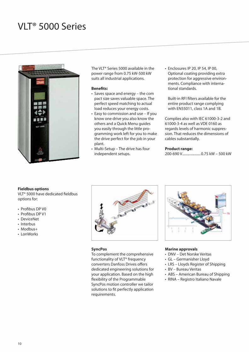
The VLT® Series 5000 available in the
power range from 0.75 kW-500 kW
suits all industrial applications.
Benefi ts:
• Saves space and energy – the com
pact size saves valuable space. The
perfect speed matching to actual
load reduces your energy costs.
• Easy to commission and use – If you
know one drive you also know the
others and a Quick Menu guides
you easily through the little pro-
gramming work left for you to make
the drive perfect for the job in your
plant.
• Multi-Setup – The drive has four
independent setups.
• Enclosures IP 20, IP 54, IP 00,
Optional coating providing extra
protection for aggressive environ-
ments. Compliance with interna-
tional standards.
Built-in RFI fi lters available for the
entire product range complying
with EN55011, class 1A and 1B.
Complies also with IEC 61000-3-2 and
61000-3-4 as well as VDE 0160 as
regards levels of harmonic suppres-
sion. That reduces the dimensions of
cables substantially.
Product range:
200-690 V ..................... 0.75 kW – 500 kW
SyncPos
To complement the comprehensive
functionality of VLT® frequency
converters Danfoss Drives off ers
dedicated engineering solutions for
your application. Based on the high
fl exibility of the Programmable
SyncPos motion controller we tailor
solutions to fi t perfectly application
requirements.
Marine approvals
• DNV – Det Norske Veritas
• GL – Germanisher Lloyd
• LRS – Lloyds Register of Shipping
• BV – Bureau Veritas
• ABS – American Bureau of Shipping
• RINA – Registro Italiano Navale
Fieldbus options
VLT® 5000 have dedicated fi eldbus
options for:
• Profi bus DP V0
• Profi bus DP V1
• DeviceNet
• Interbus
• Modbus+
• LonWorks
Specifi cations
11
Mains supply (L1, L2, L3):Supply voltage:200-240 V units ...................................................3 x 200/208/220/230/240 V ±10%380-500 V units ..........................................3 x 380/400/415/440/460/500 V ±10%525-600 V units ............................................................3 x 525/550/575/600 V ±10%Supply frequency:Max imbalance of supply voltage: ................................................ 48-62 Hz +/- 1%True Power factor (λ) ......................................................0.90 nominal at rated loadDisplacement Power Factor (cos ф) ...........................................near unity (>0.98)No. of switchings on supply input L1, L2, L3 ...................... approx. 1 time/min.
VLT output data (U, V, W):Output voltage ...................................................................0-100% of supply voltageOutput frequency......................................................................................... 0 – 1000 HzRated motor voltage:200-240 V units ...................................................................... 200/208/220/230/240 V380-500 V units ....................................................380/400/415/440/460/480/500 V525-600 V units ........................................................................................ 525/550/575 VRated motor frequency ..................................................................................UnlimitedRamp times ................................................................................................ 0.05-3600 sec.
Control card, digital inputs:Number of programmable digital inputs .................................................................8Terminal nos. ....................................................................16, 17, 18, 19, 27, 29, 32, 33Voltage level ............................................................. 0-24 V DC (PNP positive logics)Voltage level, logical ’0’ .....................................................................................< 5 V DCVoltage level, logical ’1’ ..................................................................................>10 V DCMaximum voltage on input .............................................................................28 V DCInput resistance, Ri ..................................................................................................... 2 kΩScanning time per input .....................................................................................3 msec.Reliable galvanic isolation: All digital inputs are galvanically isolated from the supply voltage (PELV). In addition, the digital inputs can be isolated from the other terminals on the control card by connectingan external 24 V DC supply and opening switch 4. VLT 5001-5250, 525-600 V do not meet PELV.
Control card, analogue inputs:No. of programmable analogue voltage inputs/thermistor inputs ................2Terminal nos ...............................................................................................................53, 54Voltage level ............................................................................. 0 – ±10 V DC (scalable)Input resistance, Ri ...................................................................................................10 kΩNo. of programmable analogue current inputs .....................................................1Terminal no. ...................................................................................................................... 60Current range ......................................................................... 0/4 – ±20 mA (scalable)Input resistance, Ri .................................................................................................. 200 ΩResolution ......................................................................................................10 bit + signAccuracy on input ............................................................ Max. error 1% of full scaleScanning time per input. ....................................................................................3 msec.Terminal no. ground .......................................................................................................55Reliable galvanic isolation: All analogue inputs are galvanically isolated from the supply voltage (PELV)*as well as other inputs and outputs. * VLT 5001-5250, 525-600 V do not meet PELV.
Control card, pulse/encoder input:No. of programmable pulse/encoder inputs ...........................................................4Terminal nos .................................................................................................17, 29, 32, 33Max. frequency on terminal 17 ........................................................................... 5 kHzMax. frequency on terminals 29, 32, 33................20 kHz (PNP open collector)Max. frequency on terminals 29, 32, 33.................................. 65 kHz (Push-pull)Voltage level ............................................................. 0-24 V DC (PNP positive logics)Voltage level, logical ’0’ .....................................................................................< 5 V DCVoltage level, logical ’1’. ...................................................................................>10 V DCMaximum voltage on input ............................................................................. 28 V DCInput resistance, Ri .................................................................................................... 2 kΩScanning time per input ................................................................................... 3 msec.Resolution ......................................................................................................10 bit + signAccuracy:(100-1 kHz), terminals 17, 29, 33 .............................Max. error: 0.5% of full scale(1-5 kHz), terminal 17 ..................................................Max. error: 0.1% of full scale(1-65 kHz), terminals 29, 33.......................................Max. error: 0.1% of full scaleReliable galvanic isolation: All pulse/encoder inputs are galvanically isolated from the supply voltage (PELV)*. In addition, pulse and encoder inputs can be isolated from the other terminals on the control card by connecting an external 24 V DC supply and opening switch 4. * VLT 5001-5250, 525-600 V do not meet PELV.
Control card, digital/pulse and analogue outputs:No. of programmable digital and analogue outputs ...........................................2Terminal nos ...............................................................................................................42, 45Voltage level at digital/pulse output ......................................................0 – 24 V DCMinimum load to ground (terminal 39) at digital/pulse output ............ 600 ΩFrequency ranges (digital output used as pulse output) ....................0-32 kHzCurrent range at analogue output ........................................................ 0/4 – 20 mAMaximum load to ground (terminal 39) at analogue output ...................500 ΩAccuracy of analogue output ..................................Max. error: 1.5% of full scaleResolution on analogue output .............................................................................8 bitReliable galvanic isolation: All digital and analogue outputs are galvanically isolated from the supply voltage (PELV)*, as well as other inputs and outputs. * VLT 5001-5250, 525-600 V do not meet PELV.
Control card, 24 V DC supply:Terminal nos ...............................................................................................................12, 13Max. load (short-circuit protection) ...............................................................200 mATerminal nos. ground ..............................................................................................20, 39Reliable galvanic isolation: The 24 V DC supply is galvanically isolated from the supply voltage (PELV)*, but has the same potential as the analogue outputs. * VLT 5001-5250, 525-600 V do not meet PELV.
Control card, RS 485 serial communication:Terminal nos .....................................................................68 (TX+, RX+), 69 (TX-, RX-)Reliable galvanic isolation: Full galvanic isolation.
Relay outputs:No. of programmable relay outputs ...........................................................................2Terminal nos., control card .......................................................................... 4-5 (make)Max. terminal load:(AC) on 4-5, control card. ..............................................................50 V AC, 1 A, 60 VA(DC) on 4-5, control card ............................................................75 V DC, 0.1 A, 30 W(DC) on 4-5, control card for UL/cUL applications ......................................................30 V AC, 1 A / 42.5 V DC, 1ATerminal nos., power card ....................................................1-3 (break), 1-2 (make)Max. terminal load (AC) on 1-3, 1-2, power card ............... 240 V AC, 2 A, 60 VAMax. terminal load on 1-3, 1-2, power card ....................................... 50 V DC, 2 AMin. terminal load on 1-3, 1-2, power card . 24 V DC 10 mA, 24 V AC 100 mA
Brake resistor terminals (only SB, EB, DE and PB units):Terminal nos ...............................................................................................................81, 82
External 24 Volt DC supply:Terminal nos ...............................................................................................................35, 36Voltage range ........................................ 24 V DC ±15% (max. 37 V DC for 10 sec.)Max. voltage ripple ............................................................................................... 2 V DCPower consumption ...........................15 W – 50 W (50 W for start-up, 20 msec.)Min. pre-fuse ............................................................................................................ 6 AmpReliable galvanic isolation: Full galvanic isolation if the external 24 V DC supply is also of the PELV type.
Cable lengths, cross-sections and connectors:Max. motor cable length:Screened cable .........................................................................................................150 mUnscreened cable ....................................................................................................300 mScreened cable VLT 5011 380-500 V . ...............................................................100 mScreened cable VLT 5011 525-600 V and VLT 5008, normal overload mode, 525-600 V ..................................................................... 50 mMax. brake cable length, screened cable.......................................................... 20 mMax. loadsharing cable length, screened cable ...................................25 m from frequency converter to DC barMax. cable cross-section for 24 V external DC supply -VLT 5001-5027 200-240 V; VLT 5001-5102 380-500 V; VLT 5001-5062 525-600V ................................................................... 4 mm2/10 AWGVLT 5032-5052 200-240 V; VLT 5122-5500 380-500 V; VLT 5075-5250 525-600 V. .............................................................. 2.5 mm2/12 AWGMax. cross-section for control cables. ........................................ 1.5 mm2/16 AWGMax. cross-section for serial communication .......................... 1.5 mm2/16 AWGIf UL/cUL is to be complied with, cable with temperature class 60/75°C must be used (VLT 5001 - 5062 380 - 500 V, 525 - 600 V and VLT 5001 - 5027 200 - 240V).If UL/cUL is to be complied with, cable with temperature class 75°C must be used (VLT 5072 - 5500 380 - 500 V, VLT 5032 - 5052 200 - 240 V, VLT 5075 - 5250 525 - 600 V).Connectors are for use of both copper and aluminium cables, unless other is specifi ed.

VLT® 5000 Flux
12
The VLT® 5000 Flux is an extension of
the VLT® 5000 series.
Full torque control under acceleration
as well as very accurate speed control
even at low speed or standstill can be
obtained.
Flux control is the future technology
for high performance drives. It pro-
vides excellent dynamics and accu-
racy, suited for drives systems with
and without feedback.
SyncPos
SyncPos makes VLT® 5000 Flux highly
programmable and provides synchro-
nising and positioning
Flux principle
The fl ux principle provides high shaft
performance (Torque control about
3 ms), excellent synchronizing also at
very low speed. Speed accuracy with
open loop: +/- 0.5 % (8 rpm) and with
closed loop +/0.001 % (0.02 rpm).
Flux control provides 180% accelera-
tion torque (0.5 sec), 160% holding
torque at 0 RPM for 60 sec (closed
loop). The accuracy of torque control
is: closed loop +/- 10%.
Plug-in terminals
Plug-in terminals for motor and
control cables
Shaft
A_phi
The VLT® 5000 Flux features automa-
tic acquisition of motor equivalent
circuit diagram and provides 100%
control of fl ux and torque, taking the
system inertia into account.
The VLT® 5000 Flux provides up to
160% torque from 0 to rated speed.

Specifi cations
13
Mains supply (L1, L2, L3):Supply voltage 200-240 V units....................3 x 200/208/220/230/240 V ±10%Supply voltage 380-500 V units...........3 x 380/400/415/440/460/500 V ±10%Supply frequency ................................................................................. 48-62 Hz +/-1%
Max imbalance of supply voltage:VLT 5001-5011, 380-500 V and VLT 5001-5006, 200-240 V ............................ ±2.0% of rated supply voltageVLT 5016-5062, 380-500 V and VLT 5008-5027, 200-240 V ............................ ±1.5% of rated supply voltageVLT 5072-5500, 380-500 V and VLT 5032-5052, 200-240 V ............................ ±3.0% of rated supply voltageTrue Power factor (λ) ......................................................0.90 nominal at rated loadDisplacement Power Factor (cos ф) ...........................................near unity (>0.98)No. of switchings on supply input L1, L2, L3 ...................... approx. 1 time/min.
VLT® output data (U, V, W):Output voltage ...................................................................0-100% of supply voltageOutput frequency..................................................................... 0 – 132 Hz, 0 – 300 HzRated motor voltage, 200-240 V units .......................... 200/208/220/230/240 VRated motor voltage, 380-500 V units ........380/400/415/440/460/480/500 VRated motor frequency. ...................................................................................50/60 HzSwitching on output .......................................................................................UnlimitedRamp times ................................................................................................ 0.01-3600 sec.
Control card, digital inputs:Number of programmable digital inputs .................................................................8Terminal nos .....................................................................16, 17, 18, 19, 27, 29, 32, 33Terminal number for none programmable digital input ..................................37Voltage level ............................................................. 0-24 V DC (PNP positive logics)Voltage level, logical ’0’ ....................................................................................< 5 V DCVoltage level, logical ’1’ ...................................................................................>10 V DCMaximum voltage on input ..............................................................................28 V DCInput resistance, Ri(terminals 16, 17, 18, 19, 27, 32, 33) ............................... 4 kΩInput resistance, Ri(terminal 29) ........................................................................... 2 kΩScanning time per input .....................................................................................3 msec.Reliable galvanic isolation: All digital inputs are galvanically isolated from the supply voltage (PELV). In addition, the digital inputs can be isolated from the other terminals on the control card by connecting an external 24 V DC supply and opening switch 4.
Control card, analogue inputs:No. of programmable analogue voltage inputs/thermistor inputs ................2Terminal nos ...............................................................................................................53, 54Voltage level. ............................................................................ 0 – ±10 V DC (scalable)Input resistance, Ri. ..................................................................................................10 kΩNo. of programmable analogue current inputs .....................................................1Terminal no. .......................................................................................................................60Current range .........................................................................0/4 – ±20 mA (scalable)Input resistance, Ri ...................................................................................................200 ΩResolution ......................................................................................................10 bit + signAccuracy on input. ........................................................... Max. error 1% of full scaleScanning time per input .....................................................................................3 msec.Terminal no. ground .......................................................................................................55Reliable galvanic isolation: All analogue inputs are galvanically isolated from the supply voltage (PELV) as well as other inputs and outputs.
Control card, pulse input:No. of programmable pulse inputs .............................................................................1Terminal no ........................................................................................................................29Max. frequency on terminal 29 (PNP open collector) ...............................20 kHzMax. frequency on terminal 29 (Push-pull) ...................................................65 kHzVoltage level ............................................................. 0-24 V DC (PNP positive logics)Voltage level, logical ’0’ .....................................................................................< 5 V DCVoltage level, logical ’1’ ...................................................................................>10 V DCMaximum voltage on input ..............................................................................28 V DCInput resistance, Ri ..................................................................................................... 2 kΩScanning time per input .....................................................................................3 msec.Resolution ......................................................................................................10 bit + signAccuracy (100-1 kHz), terminal 29 ..........................Max. error: 0.5% of full scaleAccuracy (1-65 kHz), terminal 29 ............................Max. error: 0.1% of full scaleReliable galvanic isolation: All pulse inputs are galvanically isolated from the supply voltage (PELV). In addition, pulse inputs can be isolated from the other terminals on the control card by connecting an external 24 V DC supply and opening switch 4.
Control card, encoder input:No. of programmable encoder input connector ...................................................1Input terminal nos .......................................................................73, 74, 75, 76, 77, 78Voltage level ....................................................................................................RS 422/485Maximum voltage on input ..............................................................................±7 V DCInput resistance, Ri ...................................................................................................140 ΩMax. input frequency ........................................................................................ 250 kHzSupply terminal nos ................................................................................................47, 49Supply voltage ............................................................................................................... 5 VMax. supply current .............................................................................................250 mAReliable galvanic isolation: All encoder inputs are galvanically isolated from the supply voltage (PELV). In addition, encoder inputs can be isolated from the other terminals on the control card by connecting an external 24 V DC supply and opening switch 4.
Control card, digital/pulse outputs:No. of programmable digital outputs ........................................................................2Terminal nos. ................................................................................................................6, 46Voltage level at digital/pulse output. ....................................................0 – 24 V DCMinimum load to ground (terminal 39) at digital/pulse output .............600 ΩFrequency ranges (digital output used as pulse output) ........ 100 HZ-50 kHzRefresh time .................................................................................................................3 msAccuracy ............................................................................................±0.1% of full rangeGalvanic isolation: All digital outputs are galvanically isolated from the supply voltage (PELV) as well as other inputs and outputs.
Control card, analogue outputs:No. of programmable digital outputs ........................................................................2Terminal nos ...............................................................................................................42, 45Current range at analogue output ........................................................ 0/4 – 20 mAMaximum load to ground (terminal 39) at analogue output ...................500 ΩAccuracy of analogue output ..................................... Max. error: 1% of full scaleResolution on analogue output .............................................................................8 bitGalvanic isolation: All analogue outputs are galvanically isolated from the supply voltage (PELV) as well as other inputs and outputs.
Control card, 24 V DC supply:Terminal nos ...............................................................................................................12, 13Max. load (short-circuit protection) ...............................................................200 mATerminal nos. ground ..............................................................................................20, 39Reliable galvanic isolation: The 24 V DC supply is galvanically isolated from the supply voltage (PELV), but has the same potential as the analogue outputs.
Control card, RS 232 / RS 485 serial communication:RS 232 ......................................................................................................RJ-11 connectorTerminal nos .....................................................................68 (TX+, RX+), 69 (TX-, RX-)Full galvanic isolation.
Relay outputs:No. of programmable relay outputs ...........................................................................2Terminal nos., control card .......................................................................... 4-5 (make)Max. terminal load:(AC) on 4-5, control card ...............................................................50 V AC, 1 A, 60 VA(DC-1, IEC847) on 4-5, control card ........................................75 V DC, 0.1 A, 30 W(DC-1, IEC947) on 4-5, control card for UL/cUL applications ................................................30 V AC, 1 A / 42.5 V DC, 1ATerminal nos., power card. ...................................................1-3 (break), 1-2 (make)Max. terminal load (AC) on 1-3, 1-2, power card . ................40 V AC, 2 A, 60 VAMax. terminal load (DC-1, IEC947) on 1-3, 1-2, power card ......... 50 V DC, 2 AMin. terminal load on 1-3, 1-2, power card. 24 V DC 10 mA, 24 V AC 100 mA
Brake resistor terminals (only SB, EB, DE and PB units):Terminal nos. .............................................................................................................81, 82
External 24 Volt DC supply:Terminal nos ...............................................................................................................35, 36Voltage range ........................................ 24 V DC ±15% (max. 37 V DC for 10 sec.)Max. voltage ripple ................................................................................................ 2 V DCPower consumption ...........................15 W – 50 W (50 W for start-up, 20 msec.)Min. pre-fuse ............................................................................................................ 6 AmpReliable galvanic isolation: Full galvanic isolation if the external 24 V DC supply is also of the PELV type.
VLT® HVAC Drive
14
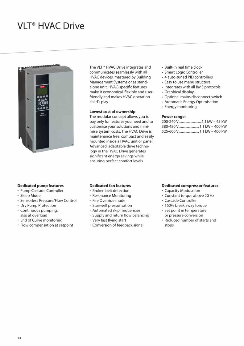
The VLT ® HVAC Drive integrates and
communicates seamlessly with all
HVAC devices, mastered by Building
Management Systems or as stand-
alone unit. HVAC-specifi c features
make it economical, fl exible and user-
friendly and makes HVAC operation
child’s play.
Lowest cost of ownership
The modular concept allows you to
pay only for features you need and to
customise your solutions and mini-
mise system costs. The HVAC Drive is
maintenance free, compact and easily
mounted inside a HVAC unit or panel.
Advanced, adaptable drive techno-
logy in the HVAC Drive generates
signifi cant energy savings while
ensuring perfect comfort levels.
• Built-in real time clock
• Smart Logic Controller
• 4 auto-tuned PID controllers
• Easy to use menu structure
• Integrates with all BMS protocols
• Graphical display
• Optional mains disconnect switch
• Automatic Energy Optimisation
• Energy monitoring
Power range:
200-240 V ...........................1.1 kW – 45 kW
380-480 V ........................ 1.1 kW – 400 kW
525-600 V ........................ 1.1 kW – 400 kW
Dedicated pump features• Pump Cascade Controller• Sleep Mode• Sensorless Pressure/Flow Control• Dry Pump Protection• Continuous pumping,
also at overload• End of Curve monitoring• Flow compensation at setpoint
Dedicated fan features• Broken belt detection• Resonance Monitoring• Fire Override mode• Stairwell pressurisation• Automated skip frequencies• Supply and return fl ow balancing• Very fast fl ying start• Conversion of feedback signal
Dedicated compressor features• Capacity Modulation• Constant torque above 20 Hz• Cascade Controller• 160% break away torque • Set point in temperature
or pressure conversion• Reduced number of starts and
stops

Specifi cations
15
Mains supply (L1, L2, L3):Supply voltage: ...................................................................................200-240 V ±10%Supply voltage: ...................................................................................380-500 V ±10%Supply voltage: ...................................................................................525-600 V ±10%Supply frequency ..............................................................................................50/60 HzDisplacement Power Factor (cos φ) near unity .......................................... (> 0.98)Switching on input supply L1, L2, L3............................................... 1-2 times/min.
Output data (U, V, W):Output voltage ...................................................................0-100% of supply voltageSwitching on output .......................................................................................UnlimitedRamp times .................................................................................................. 1 – 3600 sec.Closed loop ..........................................................................................................0-132 Hz
Digital inputs:Programmable digital inputs, FC 102: .....................................................................6*Logic .................................................................................................................PNP or NPNVoltage level ....................................................................................................0 – 24 VDC*2 can be used as digital outs
Analog inputs:Analog inputs ....................................................................................................................2Modes ................................................................................................. Voltage or currentVoltage level ............................................................................ -10 to +10 V (scaleable)Current level ......................................................................... 0/4 to 20 mA (scaleable)
Pulse inputs:Programmable pulse inputs .........................................................................................2Voltage level ............................................................ 0 – 24 VDC (PNP positive logic)Pulse input accuracy ............................................................................ (0.1 – 110 kHz) Utize some of the digital inputs
Analog output:Programmable analog outputs ....................................................................................1Current range at analog output ............................................................ 0/4 – 20 mA
Relay outputs:Programmable relay outputs: .......................................................................................2(240 VAC, 2 A and 400 VAC, 2 A)
Fieldbus communication:Standard built in: Optional:• FC Protocol • LonWorks• N2 Metasys • BACnet• FLN Apogee • DeviceNet• Modbus RTU • Profi bus
Cable lengths and cross sections:Max. motor cable length:Screened/armoured ............................................................VLT® HVAC Drive: 150 mUnscreened/unarmoured..................................................VLT® HVAC Drive: 300 mMax. cross section to motor, mains, load sharing and brake (see section Electrical Data for more information), (1.1 kW – 7.5 kW) ...................................................................................4 mm2/10 AWGMax. cross section to motor, mains, load sharing and brake (see section Electrical Data for more information), (11-18.5 kW) ............................................................................................16 mm2/6 AWGMax. cross section to motor, mains, load sharing and brake (see section Electrical Data for more information), (22-30 kW) ................................................................................................35 mm2/2 AWGMaximum cross section to control terminals: Rigid wire .................................................................1.5 mm2/16 AWG (2 x 0.75 mm2)Flexible cable ..........................................................................................1 mm2/18 AWGCable with enclosed core ............................................................... 0.5 mm2/20 AWGMinimum cross section to control terminals ...........................................0.25 mm2
Application optionsA wide range of integrated HVAC options can be fi tted in the drive:
General purpose I/O option: 3 digital inputs, 2 digital outputs, 1 analog current output, 2 analog voltage inputs
Relay option: 3 relay outputs
Analogue I/O option: 3 Pt1000 / Ni1000 inputs, 3 analog voltage outputs
External 24 VDC supply option :24 VDC external supply can be connected to supply control- and option cards.
Brake chopper option:Built in resistor for removing energy in case of high dynamics or high inertia loads.
Ambient temperature rating: 50C
Power optionsDanfoss Drives off ers a wide range of external power options for use together with our FC102 drive in critical networks or applications:
• Advanced harmonic fi lters: For critical demands on harmonic distortion
• dv/dt fi lters: For special demands on motor isolation protection• Sine fi lters (LC fi lters): For noiseless motor
HVAC PC software• MCT 10 – ideal for commissioning and servicing the drive• VLT HVAC Planet – an interactive design guide including application examples• VLT Energy Box – comprehensive energy analysis tool, shows the drive pay-back time• MCT 31 – harmonics calculations tool

VLT® 6000 HVAC
16
The Danfoss VLT® 6000 HVAC, dedi-
cated to HVAC applications, provides
unsurpassed performance, energy
savings and improved control of
HVAC systems – including interfacing
with building management systems.
Precise control of temperature, pres-
sure and fl ow in HVAC applications
results in the best environmental per-
formance for building owners and
operators.
Range:
1.1 – 400 kW ........................... (380-460 V)
Fan benefi ts:
• Bypass. The fan motor steps over
speeds which cause mechanical
vibration.
• Sleep Mode. The drive automatically
stops cooling when temperature is
at a low level for a pre-determined
time.
• De-Icing. Reverses the fan to remove
ice accumulation from intake lou-
vres. The VLT® drive can reverse
airfl ow direction for timed durations
to prevent ice accumulation for
both the intake louvres and exhaust
fan blades.
• Motor Preheat. To extend the life
of a motor in a damp environment,
a small amount of current can be
trickled into the motor to protect
it from condensation and eff ects of
a cold start.
Easy to commision and use
If you know one drive you also know
the others. A Quick Menu guides you
easily through the little programming
work left for you to make the drive
perfect for the job in your plant.
The VLT® 6000 HVAC provides full
control of the motor directly from the
user interface. “HAND START” enables
start and control of motor speed,
“OFF” turns off the motor and “AUTO
START” shifts control to digital inputs
and/or serial communication.
Performance and energy saving
Using frequency converters in HVAC
systems is mostly a question of
ultimate energy savings. VLT® 6000
HVAC is designed with HVAC systems
in mind.
Consequently it contains a series of
HVAC dedicated functionalities.
• Automatic Energy Optimizer, makes
it possible to save up to an additio-
nal 5-10% on the energy bill. This
function optimises the magnetising
current to the motor according to
the specifi c load.
• The sleep mode function. If a pump
or fan is running at low speed and
not really contributing to the
controlled parameter, e.g. tempera-
ture, pressure etc. it is turned off
automatically. When the system
again calls for energy, the drive
starts up the motor again.
• Frequency bypass. The drive can
be programmed to bypass up to
4 frequencies avoiding frequencies
that provoke resonance between
the pump/fan and the cabinet. that
creates noise and eventually cause
damage to the components.
• Sensorless Pump Control. For pump
OEM’s Danfoss Drives off ers a new
unique feature called Sensorless
Pump Control. This feature enables
the drive to control pressure in a
water system without using a
pressure transmitter. This saves
costs for the pump manufacturer in
commissioning and direct costs in
transmitter, installation etc.

Specifi cations
17
Mains supply (L1, L2, L3):Supply voltage 200 - 690 V units ........................................ 3 x 200 – 690 V, ±10%Supply frequency .................................................................................48 – 62 Hz ± 1%Max. imbalance of supply voltage ...................................................................... ± 3%VLT 6002-6011, 380-460 V and 525-600 V and VLT 6002-6005, 200-240 V ............................ ±2.0% of rated supply voltageVLT 6016-6072, 380-460 V and 525-600 V and VLT 6006-6032, 200-240 V ............................ ±1.5% of rated supply voltageVLT 6102-6550, 380-460 V and VLT 6042-6062, 200-240 V ................................... ±3.0% of rated supply voltageVLT 6100-6275, 525-600 V. .......................................±3% of rated supply voltageTrue Power factor (λ) ......................................................0.90 nominal at rated loadDisplacement Power Factor (cos.ф) ...........................................near unity (>0.98)No. of switches on supply input L1, L2, L3 .......................approx. 1 time/2 min.Max. short-circuit current ..............................................................................100.000 A
Output data (U, V, W):Output voltage. ...............................................................0 – 100% of supply voltageOutput frequency 6002-6032, 200-240V .......................0 – 120 Hz, 0 – 1000 HzOutput frequency......................................................................................... 0 – 1000 HzRated motor voltage:200-240 V units ...................................................................... 200/208/220/230/240 V380-460 V units ...................................................................... 380/400/415/440/460 V525-600 V units ........................................................................................ 525/550/575 VRated motor frequency ....................................................................................50/60 HzSwitching on output .......................................................................................UnlimitedRamp times .................................................................................................. 1 – 3600 sec.
Torque characteristics:Starting torque ...................................................................................... 130% for 1 min.Starting torque (parameter 110 High break-away torque) ................................. 160% for 0.5 sec.Acceleration torque ................................................................................................. 100%Overload torque ....................................................................................................... 110%
Control card, digital inputs:Number of programmable digital inputs .................................................................8Terminal nos .....................................................................16, 17, 18, 19, 27, 29, 32, 33Voltage level ............................................................. 0-24 V DC (PNP positive logics)Voltage level, logical ’0’ .....................................................................................< 5 V DCVoltage level, logical ’1’ ..................................................................................>10 V DCMaximum voltage on input .............................................................................28 V DCInput resistance, Ri. ........................................................................................................2 kScanning time per input. ....................................................................................3 msec.Reliable galvanic isolation: All digital inputs are galvanically isolated from the supply voltage (PELV). In addition, the digital inputs can be isolated from the other terminals on the control card by connecting an external 24 V DC supply and opening switch 4.
Control card, analogue inputsNo. of programmable analogue voltage inputs/thermistor inputs ............... 2Terminal nos ...............................................................................................................53, 54Voltage level ................................................................................0 – 10 V DC (scalable)Input resistance, Ri ......................................................................................approx. 10 kNo. of programmable analogue current inputs .....................................................1Terminal no ground ........................................................................................................55Current range ............................................................................ 0/4 – 20 mA (scalable)Input resistance, Ri. ......................................................................................................200Resolution ......................................................................................................10 bit + signAccuracy on input ............................................................ Max. error 1% of full scaleScanning time per input .....................................................................................3 msec.Reliable galvanic isolation: All analogue inputs are galvanically isolated from the supply voltage (PELV) and other high-voltage terminals.
Control card, pulse input:No. of programmable pulse inputs .............................................................................3Terminal nos ........................................................................................................17, 29, 33Max. frequency on terminal 17 ........................................................................... 5 kHzMax. frequency on terminals 29, 33.......................20 kHz (PNP open collector)Max. frequency on terminals 29, 33.......................................... 65 kHz (Push-pull)Voltage level ............................................................. 0-24 V DC (PNP positive logics)Voltage level, logical ’0’ .....................................................................................< 5 V DCVoltage level, logical ’1’ .................................................................................. >10 V DCMaximum voltage on input ..............................................................................28 V DCInput resistance, Ri. ........................................................................................................2 kScanning time per input ................................................................................... 3 msec.Resolution ......................................................................................................10 bit + sign
Accuracy:(100-1 kHz), terminals 17, 29, 33 ............................Max. error: 0.5% of full scale(1-5 kHz), terminal 17 . ................................................Max. error: 0.1% of full scale(1-65 kHz), terminals 29, 33 ......................................Max. error: 0.1% of full scaleReliable galvanic isolation: All pulse inputs are galvanically isolated from the supply voltage (PELV). In addition, pulse inputs can be isolated from the other terminals on the control card by connecting an external 24 V DC supply and opening switch 4.
Control card, digital/pulse and analogue outputs:No. of programmable digital and analogue outputs ...........................................2Terminal nos .............................................................................................................. 42, 45Voltage level at digital/pulse output ......................................................0 – 24 V DCMinimum load to ground (terminal 39) at digital/pulse output .................600Frequency ranges (digital output used as pulse output ......................0-32 kHzCurrent range at analogue output ........................................................ 0/4 – 20 mAMaximum load to ground (terminal 39) at analogue output .......................500Accuracy of analogue output ..................................Max. error: 1.5% of full scaleResolution on analogue output .............................................................................8 bitReliable galvanic isolation: All digital and analogue outputs are galvanically isolated from the supply voltage (PELV) and other high-voltage terminals.
Control card, 24 V DC supply:Terminal nos ...............................................................................................................12, 13Max. load .................................................................................................................200 mATerminal nos. ground ..............................................................................................20, 39Reliable galvanic isolation: The 24 V DC supply is galvanically isolated from the supply voltage (PELV), but has the same potential as the analogue outputs.
Control card, RS 485 serial communication:Terminal nos .....................................................................68 (TX+, RX+), 69 (TX-, RX-)Reliable galvanic isolation: Full galvanic isolation (PELV).
Relay outputs:No. of programmable relay outputs ...........................................................................2Terminal nos., control card .......................................................................... 4-5 (make)Max. terminal load:(AC) on 4-5, control card ...............................................................50 V AC, 1 A, 60 VA(DC-1 (IEC 947)) on 4-5, control card .........................................75 V DC, 1 A, 30 W(DC-1) on 4-5, control card for UL/cUL applications ....................................................... 30V AC, 1 A /42.5 V DC, 1ATerminal nos., power card and relay card .......................1-3 (break), 1-2 (make)Max. terminal load (AC) on 1-3, 1-2 power card ................ 240 V AC, 2 A, 60 VAMax. terminal load DC-1 (IEC 947) on 1-3, 1-2, power card and relay card ........................................................................ 50 V DC, 2 AMin. terminal load on 1-3, 1-2, power card ............................................................ 24 V DC, 10 mA, 24 V AC, 100 mA
External 24 Volt DC supply (only with VLT 6152-6550, 380-460 V):Terminal nos ...............................................................................................................35, 36Voltage range ........................................ 24 V DC ±15% (max. 37 V DC for 10 sec.)Max. voltage ripple ................................................................................................ 2 V DCPower consumption ...........................15 W – 50 W (50 W for start-up, 20 msec.)Min. pre-fuse ............................................................................................................ 6 AmpReliable galvanic isolation: Full galvanic isolation if the external 24 V DC supply is also of the PELV type.
Cable lengths and cross-sections:Max. motor cable length:screened cable .........................................................................................................150 mUnscreened cable ....................................................................................................300 mScreened cable VLT 6011 380-460 V .................................................................100 mScreened cable VLT 6011 525-600 V ................................................................... 50 mMax. DC-bus cable length, screened cable ...................................................... 25 mfrom frequency converter to DC bar.Max. cross-section for:24 V external DC supply ................................................................ 2.5 mm2 /12 AWGControl cables .................................................................................... 1.5 mm2 /16 AWGSerial communication. ................................................................... 1.5 mm2 /16 AWGIf UL/cUL is to be complied with, cable with temperature class 60/75°C must be used (VLT 6002 – 6072 380 – 460 V, 525-600 V and VLT 6002 – 6032 200 – 240 V).If UL/cUL is to be complied with, cable with temperature class 75°C must be used(VLT 6042 – 6062 200 – 240 V, VLT 6102 – 6550 380 – 460 V, VLT 6100 – 6275 525 – 600 V).Connectors are for use of both copper and aluminium cables, unless other is specifi ed.

VLT® AQUA Drive
18
Danfoss VLT® AQUA Drive is dedicated
to water and wastewater applications.
With a wide range of powerful
standard and optional features, the
VLT® AQUA Drive provides the lowest
overall cost of ownership for water
and wastewater applications.
• Save energy
The VLT® AQUA Drive off ers consider-
able energy savings
• Save space
The compact design of the VLT®
AQUA Drive makes it easily fi t in
even small installation spaces.
• Save cost and
protect your system
with a series of pump-specifi c
features.
• Save cabinet
NEMA/UL Type 12 (IP 54/55)
enclosure solution is available
in the whole power range.
NEMA/UL Type 4X (IP 66) version
available
• Save time
VLT® AQUA Drive is designed with
the installer and operator in mind in
order to save time in installation,
commissioning and maintenance.
Power range:
200-240 V ........................ 0.25 kW – 45 kW
380-480 V ......................0.37 kW – 450 kW
525-600 V ........................ 0.75 kW – 90 kW
525-690 V .......................132 kW – 630 kW
Dedicated water features
Auto tuning of the PI controllers
With auto tuning of the PI con -
trol lers, the drive monitors how the
system reacts on corrections made by
the drive – and learns from it, so that
precise and stable operation is
achie ved quickly.
Pipe Fill Mode
Enables controlled (closed loop)
fi lling of pipes.
Prevents water hammering, bursting
water pipes or blowing off sprinkler
heads.
End of Pump Curve
detects breaks and leakage
The feature detects breaks and
leakage. End of curve triggers an
alarm, shuts off the pump, or per-
forms another user-defi ned action.
Dry Pump Protection lowers
maintenance costs
The VLT® AQUA Drive constantly
evaluates the condition of the pump,
based on internal frequency/power
measurements.
Standard cascade controller
The in-built cascade controller
controls up to three pumps with fi xed
lead pump.
Motor Alternation
This built-in logic controls alternation
between two pumps in duty/stand-by
applications. Motion of the stand-by
pump prevents sticking of the pump.
An internal timer assures equal usage
of the pumps.
Flow compensation
The flow compensation feature
reduces the pressure set point
according to the flow – which saves
energy.
Initial/Final Ramp
The initial ramp provides fast accelera-
tion of pumps to minimum speed,
from where the normal ramp takes
over. This prevents damage on thrust
and bearings.
Sensorless Pressure
or Flow Control
Sensorless pressure or fl ow control is
a patented VLT® feature that allows
pump manufacturers to control the
constant head (pressure) or fl ow
levels without the use of sensors.

19
Specifi cations
19
Mains supply (L1, L2, L3):Supply voltage .....................................................................................200-240 V ±10%Supply voltage .....................................................................................380-480 V ±10%Supply voltage .....................................................................................525-600 V ±10%Supply voltage .....................................................................................525-690 V ±10%Supply frequency ...............................................................................................50/60 HzTrue power factor (λ) .................................................................................................≥ 0.9Switching on input supply L1, L2, L3 .............................................. 1-2 times/min.
Output data (U, V, W):Output voltage ...................................................................0-100% of supply voltageSwitching on output ......................................................................................UnlimitedRamp times ...................................................................................................... 1-3600 sec.Closed loop ...........................................................................................................0-132 Hz*VLT® AQUA Drive can provide 110% current for 1 minute.Higher overload rating is achieved by oversizing the drive.
Digital inputs:Programmable digital inputs ......................................................................................6*Logic ..................................................................................................................PNP or NPNVoltage level ........................................................................................................0-24 VDC*2 can be used as digital outputs.
Analog inputs:Analog inputs .....................................................................................................................2Modes .................................................................................................. Voltage or currentVoltage level ...................................................................................0 to 10 V (scaleable)Current level .......................................................................... 0/4 to 20 mA (scaleable)
Pulse inputs:Programmable pulse inputs ..........................................................................................2Voltage level ................................................................ 0-24 VDC (PNP positive logic)Pulse input accuracy ............................................................................. (0.1 – 110 kHz) Utilize some of the digital inputs
Analog output:Programmable analog outputs ....................................................................................1Current range at analog output ............................................................. 0/4 – 20 mA
Relay outputs:Programmable relay outputs ........................................................................................2(240 VAC, 2 A and 400 VAC, 2 A)
Fieldbus communication:Standard built in: Optional:• FC Protocol • Profi bus• Modbus RTU • DeviceNet • LonWorks
Ambient temp.:Up to .............................................................................................................................. 50˚ C
A wide range of integrated water application options can be fi t into the drive:
General purpose I/O option: 3 digital inputs, 2 digital outputs, 1 analog current output, 2 analog voltage inputs.
Relay option/cascade controller option: 3 relay outputs.
External 24 VDC supply option:24 VDC external supply can be connected to supply control- and option cards.
Brake chopper option:Connected to an external brake resistor, the brake chopper limits the load on the intermediate circuit in case the motor acts as generator.
Application options3 digital inputs, 2 digital outputs, 1 analog current output, 2 analog voltage inputs.
Relay option: 3 relay outputs
Cascade controller option:Up to 8 relays. Master/slave operation.
External 24 VDC supply option:24 VDC external supply can be connected to supply control- and option cards
Brake chopper option:Connected to an external brake resistor, the brake chopper limits the load on the intermediate circuit in case the motor acts as generator.
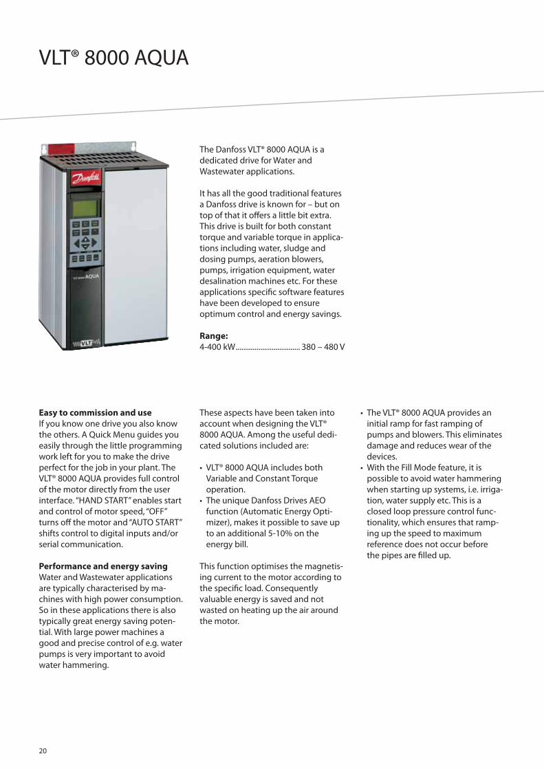
VLT® 8000 AQUA
20
The Danfoss VLT® 8000 AQUA is a
dedicated drive for Water and
Wastewater applications.
It has all the good traditional features
a Danfoss drive is known for – but on
top of that it off ers a little bit extra.
This drive is built for both constant
torque and variable torque in applica-
tions including water, sludge and
dosing pumps, aeration blowers,
pumps, irrigation equipment, water
desalination machines etc. For these
applications specifi c software features
have been developed to ensure
optimum control and energy savings.
Range:
4-400 kW .................................. 380 – 480 V
Easy to commission and use
If you know one drive you also know
the others. A Quick Menu guides you
easily through the little programming
work left for you to make the drive
perfect for the job in your plant. The
VLT® 8000 AQUA provides full control
of the motor directly from the user
interface. “HAND START” enables start
and control of motor speed, “OFF”
turns off the motor and “AUTO START”
shifts control to digital inputs and/or
serial communication.
Performance and energy saving
Water and Wastewater applications
are typically characterised by ma-
chines with high power consumption.
So in these applications there is also
typically great energy saving poten-
tial. With large power machines a
good and precise control of e.g. water
pumps is very important to avoid
water hammering.
These aspects have been taken into
account when designing the VLT®
8000 AQUA. Among the useful dedi-
cated solutions included are:
• VLT® 8000 AQUA includes both
Variable and Constant Torque
operation.
• The unique Danfoss Drives AEO
function (Automatic Energy Opti-
mizer), makes it possible to save up
to an additional 5-10% on the
energy bill.
This function optimises the magnetis-
ing current to the motor according to
the specifi c load. Consequently
valuable energy is saved and not
wasted on heating up the air around
the motor.
• The VLT® 8000 AQUA provides an
initial ramp for fast ramping of
pumps and blowers. This eliminates
damage and reduces wear of the
devices.
• With the Fill Mode feature, it is
possible to avoid water hammering
when starting up systems, i.e. irriga-
tion, water supply etc. This is a
closed loop pressure control func-
tionality, which ensures that ramp-
ing up the speed to maximum
reference does not occur before
the pipes are fi lled up.

Specifi cations
21
Mains supply (L1, L2, L3):Supply voltage:200-240 V units ...................................................3 x 200/208/220/230/240 V ±10%380-480 V units ..........................................3 x 380/400/415/440/460/480 V ±10%525-600 V units ............................................................3 x 525/550/575/600 V ±10%Supply frequency ................................................................................ 50/60 Hz +/- 1%Max. imbalance of supply voltage:VLT® 8006 - 8011 AQUA / 380 – 480 V andVLT® 8002 – 8011 AQUA / 525 – 600V .............. ±2.0% of rated supply voltageVLT® 8016 – 8072 AQUA / 525 – 600 V, 380 – 480 V, VLT® 8006 – 8032 AQUA / 200 – 240 V.............. ±1.5% of rated supply voltageVLT® 8100 – 8300 AQUA / 525 – 600 V, VLT® 8102 – 8600 AQUA / 380 – 480 V and VLT® 8042 - 8062 AQUA / 200 – 240 V ...... ±3.0% of rated supply voltageDisplacement factor/cos. ф ..........................................................near unity (> 0.98)True Power Factor (λ) ......................................................nominal 0.90 at rated loadInput Mains (L1, L2, L3) Allowable On-OFF Switching Sequnces approx ..................................................................1 time/2 min.Max. short-circuit current ....................................................................................100 kA
VLT® output data (U, V, W):Output voltage ...................................................................0-100% of supply voltageOutput frequency......................................................................................... 0 – 1000 HzRated motor voltage:200-240 V units ...................................................................... 200/208/220/230/240 V380-480 V units .............................................................380/400/415/440/460/480 V525-600 V units ........................................................................................ 525/550/575 VRated motor frequency ....................................................................................50/60 HzSwitching on output .......................................................................................UnlimitedRamp times ................................................................................................... 1 – 3600 sec.
Control card, digital inputs:Number of programmable digital inputs ............................................................... . 8Voltage level ............................................................. 0-24 V DC (PNP positive logics)Voltage level, logical “0” ....................................................................................< 5 V DCVoltage level, logical “1” ................................................................................> 10 V DCMaximum voltage on input. .............................................................................28 V DCInput resistance, Ri ..................................................................................... approx. 2 kΩScanning time per input .....................................................................................3 msec.Reliable galvanic isolation: All digital inputs are galvanically isolated from the supply voltage (PELV). In addition, the digital inputs can be isolated from the other terminals on the control card by connecting an external 24 V DC supply and opening switch 4.
Control card, analogue inputs:No. of programmable analogue voltage inputs/thermistor inputs ................2Voltage level ................................................................................0 – 10 V DC (scalable)Input resistance, Ri .....................................................................................approx. 10 ΩNo. of programmable analogue current inputs .....................................................1Terminal no. earth ...........................................................................................................55Current range ............................................................................ 0/4 – 20 mA (scalable)Input resistance, Ri .................................................................................. approx. 200 ΩResolution ......................................................................................................10 bit + signAccuracy on input ............................................................ Max. error 1% of full scaleScanning time per input .....................................................................................3 msec.Reliable galvanic isolation: All analogue inputs are galvanically isolated from the supply voltage (PELV) and other high-voltage terminals.
Control card, pulse input:No. of programmable pulse inputs .............................................................................3Max. frequency on terminal 17 ........................................................................... 5 kHzMax. frequency on terminals 29, 33.......................20 kHz (PNP open collector)Max. frequency on terminals 29, 33.......................................... 65 kHz (Push-pull)Voltage level. ............................................................ 0-24 V DC (PNP positive logics)Voltage level, logic “0” ........................................................................................< 5 V DCVoltage level, logic “1”. ....................................................................................> 10 V DCMaximum voltage on input ............................................................................. 28 V DCInput resistance, Ri. .................................................................................... approx. 2 kΩScanning time per input .....................................................................................3 msec.Resolution. .....................................................................................................10 bit + signAccuracy:(100-1 kHz), terminals 17, 29, 33 .............................Max. error: 0.5% of full scale(1-5 kHz), terminal 17. .................................................Max. error: 0.1% of full scale (1-65 kHz), terminals 29, 33......................................Max. error: 0.1% of full scaleReliable galvanic isolation: All pulse inputs are galvanically isolated from the supply voltage (PELV). In addition, pulse inputs can be isolated from the other terminals on the control card by connecting an external 24 V DC supply and opening switch 4.
Torque characteristics:Starting torque. ..................................................................................... 110% for 1 min.Starting torque (parameter 110 High break-away torque) Max. torque................................................................................................130% for 0.5 s.Acceleration torque. ................................................................................................ 100%Overload torque ....................................................................................................... 110%
Control card, digital/pulse and analogue outputs:No. of programmable digital and analogue outputs ...........................................2Terminal nos ...............................................................................................................42, 45Voltage level at digital/pulse output ......................................................0 – 24 V DCMinimum load to frame (terminal 39) at digital/pulse output ............... 600 ΩFrequency ranges (digital output used as pulse output) .................0 – 32 kHzCurrent range at analogue output ........................................................ 0/4 – 20 mAMaximum load to frame (terminal 39) at analog output . ........................500 ΩAccuracy of analogue output ..................................Max. error: 1.5% of full scaleResolution on analogue output .............................................................................8 bitReliable galvanic isolation: All digital and analog outputs are galvanically isolated from the supply voltage (PELV) and other high-voltage terminals.
External 24 Volt DC supply:(only available with VLT® 8152-8600, 380-480 V)Voltage range ........................................ 24 V DC ±15% (max. 37 V DC for 10 sec.)Max. voltage ripple ................................................................................................ 2 V DCPower consumption ............................ 15 W – 50 W (50Wfor start-up, 20 msec.)Min. pre-fuse. ........................................................................................................... 6 AmpReliable galvanic isolation: Full galvanic isolation if the external 24 V DC supply is also of the PELV type.
Control card, RS 485 serial communication:Terminal nos .....................................................................68 (TX+, RX+), 69 (TX-, RX-)Reliable galvanic isolation: Full galvanic isolation (PELV).
Relay outputs:No. of programmable relay outputs ...........................................................................2Max. terminal load:(AC) on 4-5, control card ...............................................................50 V AC, 1 A, 60 VA(DC-1 (IEC 947)) on 4-5, control card .........................................75 V DC, 1 A, 30 W(DC-1) on 4-5, control card for UL/cUL applications ......................................................30 V AC, 1 A / 42.5 V DC, 1ATerminal nos., power card and relay card .......................1-3 (break), 1-2 (make)Max. terminal load:(AC) on 1-3, 1-2 power card ...................................................... 240 V AC, 2 A, 60 VADC-1 (IEC 947) on 1-3, 1-2, power card and relay card ........................................................................ 50 V DC, 2 AMin. terminal load on 1-3, 1-2, power card 24 V DC, 10 mA, 24 V AC, 100 mA
Control card, 24 V DC supply:Terminal nos ...............................................................................................................12, 13Max. load .................................................................................................................200 mATerminal nos. earth ..................................................................................................20, 39Reliable galvanic isolation: The 24 V DC supply is galvanically isolated from the supply voltage (PELV), but has the same potential as the analogue outputs.
Cable lengths and cross-sections:Max. motor cable length:Screened cable ............................................................................................150 m/500 ftUnscreened cable .................................................................................... 300 m/1000 ftScreened cable VLT® 8011 380-480 V . ................................................100 m/330 ftScreened cable VLT® 8011 525-600 V ................................................... 50 m/164 ftMax. DC-bus cable length, screened cable ........................ 25 m/82 ft from frequency converter to DC barMax. cross-section for:24 V external DC supply ................................................................. 2.5 mm2/12 AWGControl cables ..................................................................................... 1.5 mm2/16 AWGSerial communication ..................................................................... 1.5 mm2/16 AWGConnectors are for use of both copper and aluminium cables, unless other is specifi ed.
Control characteristics: Frequency range. .............................................................................................0 – 120 HzResolution on output frequency ............................................................... ±0.003 HzSystem response time..........................................................................................3 msec.Speed, control range (open loop .................................... 1:100 of synchro. speedSpeed, accuracy (open loop). < 1500 rpm: ........................max. error ± 7.5 rpm> 1500 rpm: ........................................................max. error of 0.5% of actual speedProcess, accuracy (closed loop). < 1500 rpm: ....................max.error ± 1.5 rpm> 1500 rpm: ........................................................max. error of 0.1% of actual speedAll control characteristics are based on a 4-pole asynchronous motor.
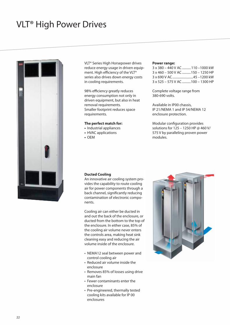
VLT® High Power Drives
22
VLT® Series High Horsepower drives
reduce energy usage in driven equip-
ment. High effi ciency of the VLT®
series also drives down energy costs
in cooling requirements.
98% effi ciency greatly reduces
energy consumption not only in
driven equipment, but also in heat
removal requirements.
Smaller footprint reduces space
requirements.
The perfect match for:
• Industrial appliances
• HVAC applications
• OEM
Power range:
3 x 380 – 440 V AC ........... 110 –1000 kW
3 x 460 – 500 V AC ...........150 – 1250 HP
3 x 690 V AC ..........................45 –1200 kW
3 x 525 – 575 V AC ...........100 – 1300 HP
Complete voltage range from
380-690 volts.
Available in IP00 chassis,
IP 21/NEMA 1 and IP 54/NEMA 12
enclosure protection.
Modular confi guration provides
solutions for 125 – 1250 HP @ 460 V/
575 V by paralleling proven power
modules.
Ducted Cooling
An innovative air cooling system pro-
vides the capability to route cooling
air for power components through a
back channel, signifi cantly reducing
contamination of electronic compo-
nents.
Cooling air can either be ducted in
and out the back of the enclosure, or
ducted from the bottom to the top of
the enclosure. In either case, 85% of
the cooling air volume never enters
the controls area, making heat sink
cleaning easy and reducing the air
volume inside of the enclosure.
• NEMA12 seal between power and
control cooling air
• Reduced air volume inside the
enclosure
• Removes 85% of losses using drive
main fan
• Fewer contaminants enter the
enclosure
• Pre-engineered, thermally tested
cooling kits available for IP 00
enclosures
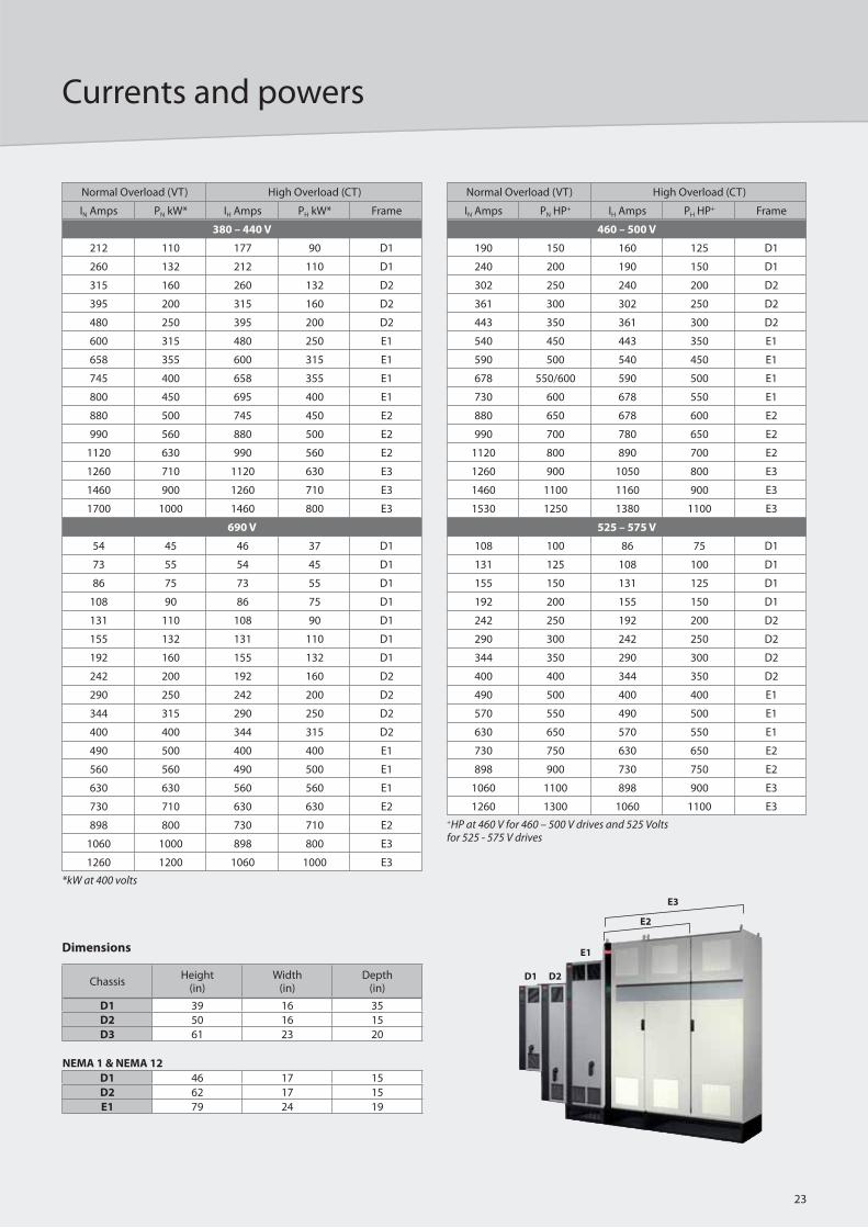
Currents and powers
23
ChassisHeight
(in)Width
(in)Depth
(in)
D1 39 16 35
D2 50 16 15
D3 61 23 20
NEMA 1 & NEMA 12
D1 46 17 15
D2 62 17 15
E1 79 24 19
Dimensions
D1 D2
E1
E2
E3
*kW at 400 volts
Normal Overload (VT) High Overload (CT)
IN Amps PN kW* IH Amps PH kW* Frame
380 – 440 V
212 110 177 90 D1
260 132 212 110 D1
315 160 260 132 D2
395 200 315 160 D2
480 250 395 200 D2
600 315 480 250 E1
658 355 600 315 E1
745 400 658 355 E1
800 450 695 400 E1
880 500 745 450 E2
990 560 880 500 E2
1120 630 990 560 E2
1260 710 1120 630 E3
1460 900 1260 710 E3
1700 1000 1460 800 E3
690 V
54 45 46 37 D1
73 55 54 45 D1
86 75 73 55 D1
108 90 86 75 D1
131 110 108 90 D1
155 132 131 110 D1
192 160 155 132 D1
242 200 192 160 D2
290 250 242 200 D2
344 315 290 250 D2
400 400 344 315 D2
490 500 400 400 E1
560 560 490 500 E1
630 630 560 560 E1
730 710 630 630 E2
898 800 730 710 E2
1060 1000 898 800 E3
1260 1200 1060 1000 E3
+HP at 460 V for 460 – 500 V drives and 525 Volts for 525 - 575 V drives
Normal Overload (VT) High Overload (CT)
IN Amps PN HP+ IH Amps PH HP+ Frame
460 – 500 V
190 150 160 125 D1
240 200 190 150 D1
302 250 240 200 D2
361 300 302 250 D2
443 350 361 300 D2
540 450 443 350 E1
590 500 540 450 E1
678 550/600 590 500 E1
730 600 678 550 E1
880 650 678 600 E2
990 700 780 650 E2
1120 800 890 700 E2
1260 900 1050 800 E3
1460 1100 1160 900 E3
1530 1250 1380 1100 E3
525 – 575 V
108 100 86 75 D1
131 125 108 100 D1
155 150 131 125 D1
192 200 155 150 D1
242 250 192 200 D2
290 300 242 250 D2
344 350 290 300 D2
400 400 344 350 D2
490 500 400 400 E1
570 550 490 500 E1
630 650 570 550 E1
730 750 630 650 E2
898 900 730 750 E2
1060 1100 898 900 E3
1260 1300 1060 1100 E3

VLT® Decentral FCD 300
24
The VLT® FCD 300 is a complete
frequency converter designed for
decentral mounting. The FCD can
be mounted on the wall close to the
motor, or directly on the motor. The
FCD 300 comes in a high enclosure
class, IP66, to withstand normal
cleaning methods. The design off ers
a smooth cleaning friendly surface
without any diffi cult to clean spots.
The FCD 300 comes in a robust
painted surface.
The decentral design reduces the
need for central control panels and
space-consuming motor control
cabinets are eliminated. Reduced
need for wiring long screened motor
cables.
Plug-and-drive
All the advanced and reliable electro-
nics needed to ensure your motors
act smoothly, responsively and eco-
nomically at each command are
hidden inside the box lid and plug
into connectors when mounted onto
the bottom section. The bottom
section contains maintenance-free
Cage Clamp connectors and looping
facilities for power and fi eldbus cables
well protected against dust, hosing
and cleaning agents. Once installed,
commissioning and upgrading can be
performed in no time by plugging in
another control lid.
Flexible installation
The FCD 300 series facilitates internal
power line looping. Terminals for
4 mm2 power cables inside the
enclosure allows connection of up
to 10+ units.
Control
Decentral drives are complete
variable speed drives to be set up and
controlled through a remote control
panel or fi eldbus communication and
Danfoss’ dedicated MCT 10 set-up
software.
Hygienic
Protected in small, tight, robust, dirt
repelling enclosures the FCD 300
meets conditions found in the food
and beverage industry, where
frequent wash downs are required.

Specifi cations
25
Mains supply:Supply voltage FCD 305-335 .........................3 x 380/400/415/440/480 V ±10%Supply frequency ...............................................................................................50/60 HzMax. imbalance on supply voltage .................. ± 2.0% of rated supply voltagePower factor (400 V) / cos. 1 ..................................................0.90/1.0 at rated loadNumber of connections at supply input L1, L2, L3 ........................ 2 times/min.
Torque characteristics:Starting torque (Constant torque) ..........................maximum 160% for 1 min.*Starting torque ........................................................maximum 180% up to 0.5 sec.*Overload current (Constant torque) .......................maximum 160% for 1 min.**Percentage relates to FC 300’s nominal current.
Control card, digital inputs:Number of programmable digital inputs .................................................................5Terminal number .................................................................................18, 19, 27, 29, 33Voltage level ............................................................ 0 – 24 V DC (PNP positive logic)Voltage level, logic ’0’ .........................................................................................< 5 V DCVoltage level, logic ’1’ ......................................................................................> 10 V DCMaximum voltage on input. .............................................................................28 V DCInput resistance, Ri (terminals 18, 19, 27) .......................................... approx. 4 kΩInput resistance, Ri (terminal 29, 33) ................................................... approx. 2 kΩAll digital inputs are galvanically isolated from the supply voltage (PELV) and other high-voltage terminals, and can be functionally separated from other control terminals by opening switch S100.
Control card, analogue inputs:Number of analogue voltage inputs ................................................................. 1 pcs.Terminal number .............................................................................................................53Voltage level ..........................................................................± 0 – 10 V DC (scaleable)Input resistance, Ri ...................................................................................approx. 10 kΩMax. voltage ..................................................................................................................20 VNumber of analogue current inputs ................................................................. 1 pcs.Terminal number .............................................................................................................60Current level ............................................................................0/4 – 20 mA (scaleable)Input resistance, Ri .................................................................................. approx. 300 ΩMax. current ..............................................................................................................30 mAResolution for analogue inputs ...........................................................................10 bitAccuracy of analogue inputs........................................ Max. error 1% of full scaleScan interval .......................................................................................................13.3 msecThe analogue inputs are galvanically isolated from the supply voltage (PELV) and other high-voltage terminals.
Control card, pulse inputs:Number of programmable pulse inputs ...................................................................2Terminal number ......................................................................................................29, 33Max. frequency at terminal 29/33 ...........................................110 kHz (Push-pull)Max. frequency at terminal 29/33 ......................................5 kHz (open collector)Min. frequency at terminal 33 .................................................................................4 HzMin. frequency at terminal 29 .............................................................................. 30 HzVoltage level . .......................................................... 0 – 24 V DC (PNP positive logic)Voltage level, logic ’0’ ........................................................................................< 5 V DCVoltage level, logic ’1’ .....................................................................................> 10 V DCMaximum voltage on input ..............................................................................28 V DCInput resistance, Ri ..................................................................................... approx. 2 kΩScan interval .......................................................................................................13.3 msecResolution ...................................................................................................................10 bitAccuracy (100 Hz – 1 kHz) terminal 33 .................Max. error: 0.5% of full scaleAccuracy (1 kHz – 67.6 kHz) terminal 33 ..............Max. error: 0.1% of full scaleThe pulse input is galvanically isolated from the supply voltage (PELV) and other high-voltage terminals.
Control card, digital/frequency output:Number of programmable digital/pulse outputs ........................................ 1 pcs.Terminal number .............................................................................................................46Voltage level at digital/frequency output ........................ 0 - 24 V DC (O.C PNP)Max. output current at digital/frequency output ......................................25 mA.Max. load at digital/frequency output................................................................ 1 kΩMax. capacity at frequency output .................................................................... 10 nFMinimum output frequency at frequency output ....................................... 16 HzMaximum output frequency at frequency output. ................................... 10 kHzAccuracy on frequency output ...............................Max. error: 0.2 % of full scaleResolution on frequency output ........................................................................10 bitThe digital output is galvanically isolated from the supply voltage (PELV) and other high-voltage terminals.
Control card, analog output:Number of programmable analog outputs .............................................................1Terminal number .............................................................................................................42Current range at analog output .............................................................. 0/4 - 20 mAMax. load to common at analog output ..........................................................500 ΩAccuracy on analog output .....................................Max. error: 1.5 % of full scaleResolution on analog output ...............................................................................10 bitThe analog output is galvanically isolated from the supply voltage (PELV) and other high-voltage terminals.
Control card, 24 V DC output:Terminal number .............................................................................................................12Max. load supplied from mains/24 V external .................................... 240/65 mAThe 24 V DC supply is galvanically isolated from the supply voltage (PELV) , but has the same potential as the analogue and digital inputs and outputs.
Control card, 10 V DC output:Terminal number ............................................................................................................50Output voltage ........................................................................................... 10.5 V ±0.5 VMax. load ...................................................................................................................15 mAThe 10 V DC supply is galvanically isolated from the supply voltage (PELV) and other high-voltage terminals.
Control card, RS 485 serial communication:Terminal number ............................................................68 (TX+, RX+), 69 (TX-, RX-)Terminal number 67 ..................................................................................................+ 5 VTerminal number 70 ...................................Common for terminals 67, 68 and 69Full galvanic isolation.
Relay outputs:Number of programmable relay outputs .................................................................1Terminal number, control card ...........................................1-3 (break), 1-2 (make)Max. terminal load (AC) on 1-3, 1-2, control card .......................... 240 V AC, 2 AMin. terminal load on 1-3, 1-2, control card 24 V DC 10 mA, 24 V AC 100 mA. The relay contact is separated from the rest of the circuit by strengthened isolation.
External 24 Volt DC supply:Terminal nos ...............................................................................................................35, 36Voltage range ......................................................21-28 V (max. 37 V DC for 10 sec.)Max. voltage ripple ................................................................................................ 2 V DCPower consumption with/without mains supply ..........................< 1 W/5-12 WReliable galvanic isolation: Full galvanic isolation if the external 24 V DC supply is also of the PELV type.
Cable lengths and cross sections:Max. motor cable length:Screened/armoured cable ..................................................................................... 10 mUnscreened/unarmoured cable ........................................................................... 10 mMax. cross section to control:Wires, rigid wire ................................................................................. 4.0 mm2/10 AWGCables, fl exible cable ....................................................................... 2.5 mm2/12 AWGCables, cable with ferrules. ............................................................ 2.5 mm2/12 AWGMax. cross section extra terminals for 24 V ext:T73 version, rigid cables ...................................................................6.0 mm2/9 AWGT73 version, fl exible cable ..................................................................4 mm2/10 AWGT73 version, cable with ferrules ....................................................... 4 mm2/10 AWGMax. cross section PE. .........................................................................10 mm2/7 AWGMax. cross section external PE for T73 version ...........................16 mm2/5 AWGIf UL/cUL is to be complied with, cable with temperature class 60/75°C must be used. Use copper wires only.
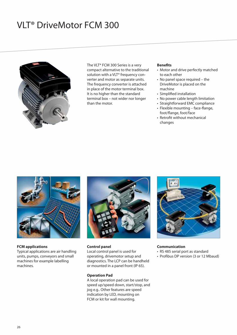
VLT® DriveMotor FCM 300
26
The VLT® FCM 300 Series is a very
compact alternative to the traditional
solution with a VLT® frequency con-
verter and motor as separate units.
The frequency converter is attached
in place of the motor terminal box.
It is no higher than the standard
terminal box – not wider nor longer
than the motor.
FCM applications
Typical applications are air handling
units, pumps, conveyors and small
machines for example labelling
machines.
Control panel
Local control panel is used for
operating, drivemotor setup and
diagnostics. The LCP can be handheld
or mounted in a panel front (IP 65).
Operation Pad
A local operation pad can be used for
speed up/speed down, start/stop, and
jog e.g.. Other features are speed
indication by LED, mounting on
FCM or kit for wall mounting.
Communication
• RS 485 serial port as standard
• Profi bus DP version (3 or 12 Mbaud)
Benefi ts
• Motor and drive perfectly matched
to each other
• No panel space required – the
DriveMotor is placed on the
machine
• Simplifi ed installation
• No power cable length limitation
• Straightforward EMC compliance
• Flexible mounting – face-fl ange,
foot/fl ange, foot/face
• Retrofi t without mechanical
changes
27
Specifi cations
27
Mains supply, TT, TN and IT* (L1, L2, L3):Supply voltage 380-480 V units...........3 x 380/400/415/440/460/480 V ±10%Supply frequency .. ............................................................................................50/60 HzMax. imbalance of supply voltage .......................± 2% of rated supply voltagePower factor/cos φ . ......................................................... max. 0.9/1.0 at rated loadNo. of switching operations on supply input L1, L2, L3 ..............................................................approx. 1 time/2 min*) Not valid for RFI class 1B units
Torque characteristics:Starting torque/overload torque .................................................... 160 % for 1 minContinuous torque.. ........................................................................................ see above
Control card, digital/pulse inputs:Number of programmable digital inputs .................................................................4Terminal nos .......................................................................................... X101-2, -3, -4, -5Voltage level ... ......................................................... 0-24 V DC (PNP positive logics)Voltage level, logic ´0´ . ......................................................................................< 5 V DCVoltage level, logic ´1´ . ...................................................................................> 10 V DCMaximum voltage on input .. .......................................................................... .28 V DCInput resistance, Ri ........................................................................................aprox. 2 kΩScanning time .......................................................................................................20 msec
Control card, pulse input:No. of programmable pulse inputs .............................................................................1Terminal nos. .......................................................................................................... X101-3Max. frequency on terminal 3, open collector/push pull 24 V .............................................................. 8 kHz/70 kHzResolution ...................................................................................................................10 bitAccuracy (0.1-1 kHz), terminal 3 ..............................Max. error: 0.5% of full scaleAccuracy (1-12 kHz), terminal 3... ............................Max. error: 0.1% of full scale
Control card, analogue inputs:No. of programmable analogue voltage inputs . ...................................................1Terminal nos ............................................................................................................ X101-2Voltage level ...............................................................................0 – 10 V DC (scalable)Input resistance, Ri... ................................................................................approx. 10 kΩNo. of programmable analogue current inputs . ...................................................1Terminal no. . ........................................................................................................... X101-1Current range . ...............................................................................0 – 20 mA (scalable)Input resistance, Ri. . ............................................................................ .approx. 500 kΩResolution ......................................................................................................................9 bitAccuracy on input .. ......................................................... Max. error 1% of full scaleScanning time .....................................................................................................20 msec.
Control card, digital/pulse and analogue outputs:No. of programmable digital and analogue outputs ...........................................1Terminal nos ............................................................................................................ X101-9Voltage level at digital output/load ......................................... 0 – 24 V DC/25 mACurrent at analoque output .. ......................................................................0 – 20 mAMaximum load to frame (terminal 8) at analogue output . ............................................................................ RLOAD ≤ 500 ΩAccuracy of analogue output ... ..............................Max. error: 1.5% of full scaleResolution on analogue output. . ..........................................................................8 bit
Relay output:No. of programmable outputs ......................................................................................1Terminal nos .................................................1-2 (make), 1-3 (brake) terminal X102Voltage level at contact/load (AC)... .................................... 250 V AC, 5A-AC loadVoltage level at contact/load (DC) ........................................................ 30 V DC, 5A;
40 V DC, 2A 100 V DC, 0.5A
Control card, RS 485 serial communication:Terminal nos ...................................................................................................... X100-1, -2
Control characteristics (frequency converter):Frequency range ..............................................................................................0 – 132 HzResolution on output frequency ..........................................................................0.1%System response time.............................................................................Max. 40 msec.Speed acuracy (open loop, CT mode, 4 P motor driven in speed range 150-1500 rPm) ..................................................... +/- 15 rpm

VLT® Soft Starter MCD 100
28
MCD 100 is a cost eff ective and ex-
tremely compact soft starter for AC
motors up to 11 kW. Due to a unique
semiconductor design MCD 100 is a
true “fi t and forget” product. Selection
can be made on the basis of the
motor power – exactly as with
traditional contactors.
The range features three diff erent
products, MCD 100-001 (1,5 kW),
MCD 100-007 (7,5 kW) and
MCD 100-011 (11 kW). All sizes are
rated for line voltage up to 600 V AC.
MCD 100 products provide timed
voltage ramp up and down. Ramp
time can be individually adjusted with
rotary switches from 0,4 to 10 se-
conds. The start torque can be ad-
justed from 0 to 85% of the direct
on-line torque.
• A robust semiconductor design
– selection can be based on motor
power which ensures easy selection.
• Can be used for an almost unlimited
number of starts per hour without
derating.
Timed voltage ramp
• Micro Soft Start Controller for
motors up to 11kW
• Extremely robust SCR design with
heavy ratings as standard
• Unlimited number of starts per hour
• Contactor style design for easy
selection, installation and
commissioning
Motor torque(Voltage)
Ramp-up time0.5 -10 sec.
Ramp-down time0 -10 sec.
Time
’’Kick start’’200 msec.of max. torque
Initial Torque up to 85% of nominal torque
0%
100%
• A universal control voltage
(24-480 V AC/ V DC) – simplifi es
selection and keeps stock at a
minimum.
• A “fi t and forget” contactor design
– simplifi es installation and reduces
required panel space.
• Digitally controlled rotary switches
– secures precise settings and
simplifi es installation.
• Ratings for heavy duty as standard
– simplifi es installation and reduces
the risk of breakdown

29
Specifi cations
29
Mains supply (L1, L2, L3):MCD 100 ........................................................3 x 208 VAC ~ 600 VAC (+10% / -15%)Supply frequency (at start) ....................................................................45HZ – 66 Hz
Control circuit (A1, A2):MCD 100 ...................................................................24 – 480 VAC/VDC (-15% +10%)
Environmental:Degree of protection MCD 100 .............................................................................IP 20Operating Temperatures ................................ -5°C / +40°C (60°C with de-rating)Pollution Degree ............................................................................. Pollution Degree 3
EMC Emission:Equipment class (EMC) ........................................................................................ Class AConducted radio frequency emission:0.15 MHz – 0.5 MHz ....................................................................................< 90 dB (μV)0.5 MHz – 5 MHz ..........................................................................................< 76 dB (μV)5 MHz – 30 MHz ........................................................................................ 80-60 dB (μV)Radiated radio frequency emission:30 MHz – 230 MHz ................................................................................ < 30 dB (μV/m)230 MHz – 1000 MHz ........................................................................... < 37 dB (μV/m)This product has been designed for Class A equipment. Use of the product in domestic environments may cause radio interference, in which case the user may be required to employ additional mitigation methods.
EMC Immunity:Electro static discharge ...................4 kV contact discharge, 8 kV air dischargeRadio-frequency electromagnetic fi eld:0.15 MHz – 1000 MHz ................................................................................. 140 dB (μV)Rated impulse withstand voltage (Fast transients 5/50 ns – Burst) ....................................................4 kV line to earthRated insulation voltage (Surges 1.2/50 μs – 8/20 μs) ........................... 4 kV line to earth, 2 kV line to lineVoltage dip and short time interruption ................................................100 ms (at 40% nominal voltage)
Short Circuit:Rated short-circuit current MCD 100-001 ................ normal fuses: 25 A gL/gGSCR I2t rating for semiconductor fuses: ......................................................... 72 A2sRated short-circuit current MCD 100-007 ............... normal fuses: 50 A gL/gGSCR I2t rating for semiconductor fuses: 1800 ................................................... A2sRated short-circuit current MCD 100-011 ................ normal fuses: 80 A gL/gGSCR I2t rating for semiconductor fuses: .................................................... 6300 A2s
Heat Dissipation:MCD 100-001 ............................................................................................... max. 4 wattsMCD 100-007 to MCD 100-011. ...................................................... 2 watts/Ampere
Standards Approvals:UL/C-UL ......................................................................................................................UL508CE ...................................................................................................................IEC 60947-4-2

VLT® Compact Starter MCD 200
30
The Compact Starter MCD 200 cover
the power range 7.5 – 110 kW.
Due to extensive use of the latest
technology, such as new semicon-
ductor control algorithms and bypass
design, the new soft starters are very
compact and heat dissipation is at a
very low level. There is no need for
extra ventilation or bypass contactors.
This simplifi es installation and keeps
panel space at a minimum.
The MCD 200 features a variety of
accessories. Add-on modules provide
essential serial communication and a
Remote Operator module allows for
remote control and motor perform-
ance monitoring, which makes MCD
200 ideal for panel installation.
MCD 200 comes in two versions.
MCD 201 is the basic version off ering
timed voltage ramps, MCD 202 is the
ad- vanced version providing current
limit soft start, timed voltage ramp
down, and motor protection.
• Current ratings for normal and
heavy starting
• Versions for 200- 575 VAC
• Voltage ramps or current limit
ramp soft start
• Built-in motor protection
• Compact design with internal
bypass system for minimum power
loss
• Add on modules for remote
operation and serial communication
• Software for sizing, control and
monitoring
Timed voltage ramp MCD 201 Current Limit MCD202:
• Compact Soft Starter for motors
up to 110kW
• Voltage ramps, current limit start
and integrated motor protection
• Integral bypass design reduce heat
dissipation
• Wide power range with advanced
accessory modules
Optional:
• Modules for serial communication
• Remote operation kit
• PC software
• Remote operation kit
Ramp-up(2-20 seconds, Full Voltage Start)
Initial Torque(30-75%)
100%U
Ramp Time(2, 5, 15 seconds, OFF)
400%
300%
200%
100%
Initial Start Current(150% FLC, 200% FLC, 250% FLC)
I
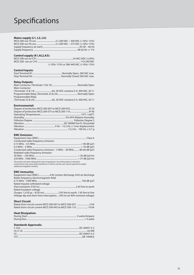
31
Specifi cations
31
Mains supply (L1, L2, L3):MCD 200-xxx-T4-xxx . ..................................3 x 200 VAC ~ 440 VAC (+10%/-15%)MCD 200-xxx-T6-xxx ...................................3 x 200 VAC ~ 575 VAC (+10%/-15%)Supply frequency (at start) ...................................................................45 HZ – 66 HzSupply frequency ................................................................................ 48-62 Hz +/-1%
Control supply (A1,AL2,A3):MCD 200-xxx-xx-CV1...................................................................24 VAC/VDC (±20%)MCD 200- xxx-xx-CV3 ............................................................................... 110-240 VAC (+10%/-15%) or 380-440 VAC (+10%/-15%)
Control Inputs:Start Terminal N1 ......................................................Normally Open, 300 VAC max.Stop Terminal N2 .................................................... Normally Closed 300 VAC max.
Relay Outputs:Main Contactor (Terminals 13 & 14) ...............................................Normally OpenMain Contactor (Terminals 13 & 14) ...............................6A, 30 VDC resistive/2 A, 400 VAC, AC11Programmable Relay (Terminals 23 & 24) .....................................Normally OpenProgrammable Relay (Terminals 23 & 24) ...............................6A, 30 VDC resistive/2 A, 400 VAC, AC11
Environmental:Degree of protection MCD 200-007 to MCD 200-055 ...................................IP 20Degree of protection MCD 200-075 to MCD 200-110 ...................................IP 00Operating Temperatures ..........................................................................-10°C /+60°CHumidity ............................................................................ 5%-95% Relative HumidityPollution Degree . .......................................................................... Pollution Degree 3Vibration ..........................................................................IEC 60068 Test Fc SinusoidalVibration .........................................................4 Hz – 13.2 Hz: ± 1mm displacementVibration .................................................................................13.2 Hz – 100 Hz: ± 0.7 g
EMC Emission:Equipment class (EMC) ........................................................................................ Class AConducted radio frequency emission:0.15 MHz – 0.5 MHz ....................................................................................< 90 dB (μV)0.5 MHz – 5 MHz ..........................................................................................< 76 dB (μV)Conducted radio frequency emission – 5 MHz – 30 MHz .......... 80-60 dB (μV)Radiated radio frequency emission:30 MHz – 230 MHz ................................................................................ < 30 dB (μV/m)230 MHz –1000 MHz ............................................................................ < 37 dB (μV/m)This product has been designed for Class A equipment. Use of the product in domestic environments may cause radio interference, in which case the user may be required to employ additional mitigation methods.
EMC Immunity:Equipment class (EMC) ....................4 kV contact discharge, 8 kV air dischargeRadio-frequency electromagnetic fi eld:0.15 MHz - 1000 MHz .................................................................................. 140 dB (μV)Rated impulse withstand voltage (Fast transients 5/50 ns) ...................................................................2 kV line to earthRated insulation voltage (Surges 1.2/50 μs – 8/20 ms) ......................... 2 kV line to earth, 1 kV line to lineVoltage dip and short time interruption ....100 ms (at 40% nominal voltage)
Short Circuit:Rated short-circuit current MCD 200-007 to MCD 200-037 ........................5 kARated short-circuit current MCD 200-045 to MCD 200-110 . .................... 10 kA
Heat Dissipation:During Start ........................................................................................... 3 watts/AmpereDuring Run ........................................................................................................... < 4 watts
Standards Approvals:C-tick .............................................................................................................IEC 60947-4-2UL/C-UL ......................................................................................................................UL508CE ...................................................................................................................IEC 60947-4-2CCC .....................................................................................................................GB 14048.6
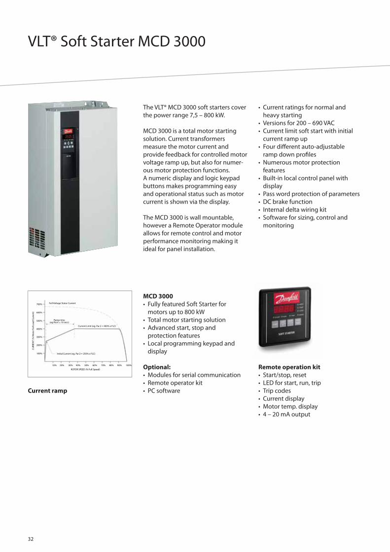
VLT® Soft Starter MCD 3000
32
The VLT® MCD 3000 soft starters cover
the power range 7,5 – 800 kW.
MCD 3000 is a total motor starting
solution. Current transformers
measure the motor current and
provide feedback for controlled motor
voltage ramp up, but also for numer-
ous motor protection functions.
A numeric display and logic keypad
buttons makes programming easy
and operational status such as motor
current is shown via the display.
The MCD 3000 is wall mountable,
however a Remote Operator module
allows for remote control and motor
performance monitoring making it
ideal for panel installation.
• Current ratings for normal and
heavy starting
• Versions for 200 – 690 VAC
• Current limit soft start with initial
current ramp up
• Four diff erent auto-adjustable
ramp down profi les
• Numerous motor protection
features
• Built-in local control panel with
display
• Pass word protection of parameters
• DC brake function
• Internal delta wiring kit
• Software for sizing, control and
monitoring
Current ramp
MCD 3000
• Fully featured Soft Starter for
motors up to 800 kW
• Total motor starting solution
• Advanced start, stop and
protection features
• Local programming keypad and
display
Optional:
• Modules for serial communication
• Remote operator kit
• PC software
Full Voltage Stator Current
CU
RREN
T (%
Mot
or F
ull L
oad
Cur
rent
)
Ramp time(eg Par.4 = 10 secs)
Current Limit (eg. Par.2 = 400% x FLC)
Initial Current (eg. Par.3 = 250% x FLC)
ROTOR SPEED (% Full Speed)
10% 20% 30% 40% 50% 60% 70% 80% 90% 100%
700%
600%
500%
400%
300%
200%
100%
Remote operation kit
• Start/stop, reset
• LED for start, run, trip
• Trip codes
• Current display
• Motor temp. display
• 4 – 20 mA output

33
Specifi cations
33
Mains supply (L1, L2, L3):Supply voltage MCD3000-T5 ..............................................3 x 200 VAC ~ 525 VAC
3 x 200 VAC ~ 440 VAC (Inside Delta Connection)Supply voltage MCD3000-T7 ................................................ x 200 VAC ~ 690 VAC
3 x 200 VAC ~ 440 VAC (Inside Delta Connection)Supply frequency (at start) ...................................50 HZ (± 2 Hz) / 60 Hz (± 2 Hz)Supply frequency (during start) .............................>45 Hz (50 Hz supply) or >55Hz (60 Hz supply)Supply frequency (during run) .............................>48 Hz (50 Hz supply) or >58 Hz (60 Hz supply)Electronics control voltage .......................................230 VAC (+10%/-15%) or 400 VAC (+10%/-15%)
Control Inputs:Start (Terminals 15 & 16) .......... Normally Open, Active 24 VDC, 8 mA approx.Stop (Terminals 17 & 18) ........Normally Closed, Active 24 VDC, 8 mA approx.Reset (Terminals 25 & 26) ......Normally Closed, Active 24 VDC, 8 mA approx.Parameter Set (Terminals 27 & 28) .................... Normally Open, Active 24 VDC, 8 mA approx.
Relay Outputs:Programmable Output A1) (Terminals 13 & 14) ..............................................................................Normally Open,
5 A @ 250 VAC/360 VA, 5 A @ 30 VDC resistiveProgrammable Output B2) (Terminals 21, 22 & 24) ............................................................................. Changeover,
5 A @ 250 VAC/360 VA, 5 A @ 30 VDC resistiveOutput C3 (Terminals 33 & 34) ..............................................................................Normally Open,
5 A@250 VAC/360 VA, 5 A@30 VDC resistive1) Programmable functions: Line contactor, Run, High current fl ag, Low current fl ag2) Programmable functions: Tripped, Output on, High current fl ag, Low current fl ag, Line contactor3) Programmable functions: Run, D.C.Brake Contactor Control, Off
Environmental:Degree of protection MCD3007 to MCD3132 . ............................................... IP 21Degree of protection MCD3185 to MCD3800 ................................................. IP 20Operating Temperatures . .......................................................................... -5°C /+60°CRated short-circuit current (with semi-conductor fuses) .........................100 kARated insulation voltage (Surges) ............... 2 kV line to earth, 1 kV line to lineRated impulse withstand voltage (Fast transients) .........................................2 kVPollution Degree . ........................................................................... Pollution Degree 3Electro static discharge ...................4 kV contact discharge, 8 kV air dischargeEquipment class (EMC) ........................................................................................ Class ARadio-frequency electromagnetic fi eld
0.15 MHz – 80 MHz: 140 dBμV 80 MHz – 1 GHz: 10 V/mThis product has been designed for Class A equipment. Use of the product in domestic environments may cause radio interference, in which case the user may be required to employ additional mitigation methods.
Standards Approvals:C√ ............................................................................................................................CISPR-11UL1 ................................................................................................................................UL508C-UL1 ....................................................................................................... CSA 22.2 No. 14CE ...................................................................................................................IEC 60947-4-21) Requires use of semi-conductor fuses. Excludes models MCD3600~MCD3800

VLT® Harmonic Filter AHF 005/010
34
The Danfoss AHF 005 and AHF 010 are
advanced harmonic fi lters not to be
confused with traditional harmonic
trap fi lters. The Danfoss harmonic
fi lters have been specially designed to
match the Danfoss frequency drives.
AHF 010 reduces the harmonic
current to less than 10% and the
AHF 005 reduces the harmonic
current to less than 5%.
Danfoss harmonic fi lters perform
excellently.
The fi gures show the reduction of
each of the sub-harmonic orders at
full load.
Calculation Danfoss has created a PC
based program MCT31 for calculation
of harmonics with diff erent principles
for suppression. It can calculate the
harmonics for Danfoss Frequency
Converters depending on actual
system (transformer, cables, other
loads etc.)
Features
• Small compact housing that fi ts
into a panel
• Easy to use in retrofi t applications
• AHF 010 reduces the total harmonic
current distortion to 10%
• AHF 005 reduces the total harmonic
current distortion to 5%
• One fi lter module can be used for
several frequency drives
• High effi ciency (> 0.98)
• User-friendly commissioning
– no adjustment necessary
• No routine maintenance required
Excellent performance
AHF 005
Hamonic order5 7 11 13 17 19 23 25
4%
3%
3%
2%
2%
1%
1%
0%
AHF 010
Hamonic order
5 7 11 13 17 19 23 25
6%
5%
4%
3%
2%
1%
0%

35
Specifi cations
35
General technical data:
The reduction of the low harmonic current emission to the rated THiD implies, that the THvD of the non-infl uenced mains voltage is lower than 2% and the ratio of short circuit power to installed load (R SCE ) is at least 66%.
Under these conditions the THiD of the mains current of the frequency converter is reduced to 10% or 5% (typical values at nominal load).
If these conditions are not or only partially fulfi lled, a signifi cant reduction of the harmonic components can still be achieved, but the rated THiD values may not be achieved.

VLT® Power Options dU/dt fi lter
36
dU/dt fi lters reduce the dU/dt values
on the motor terminal phase-to-
phase voltage. The phase-to-phase
voltage is still pulse shaped.
Compared to sine-wave fi lters, dU/dt
fi lters cut-off frequencies above the
switching frequency. Having small
inductance and capacitance, the fi lter
is cheaper.
The fi lters reduce the motor insula-
tions stress and are recommended in
applications with risk of fl ashover.
Voltage and current without fi lter Voltage and current with fi lter
The perfect solution for:
• Applications with older motors
• Aggressive environments
• Applications with frequent braking
Range
3 x 200 – 500 V
3 x 525 – 690 V
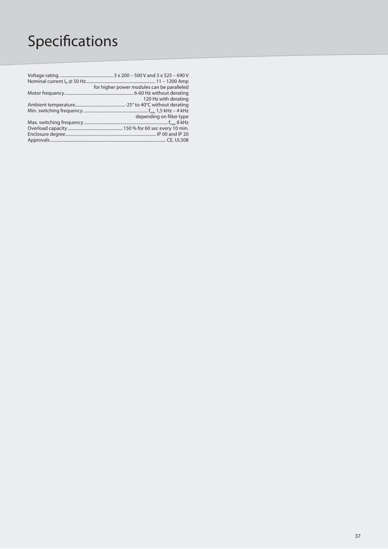
37
Specifi cations
37
Voltage rating. ................................................. 3 x 200 – 500 V and 3 x 525 – 690 VNominal current IN @ 50 Hz ................................................................ 11 – 1200 Amp
for higher power modules can be paralleledMotor frequency ................................................................ 6-60 Hz without derating
120 Hz with deratingAmbient temperature ..............................................-25° to 40°C without deratingMin. switching frequency ............................................................ fmin 1,5 kHz – 4 kHz
depending on fi lter typeMax. switching frequency .............................................................................. fmax 8 kHzOverload capacity ................................................... 150 % for 60 sec every 10 min.Enclosure degree .................................................................................... IP 00 and IP 20Approvals ........................................................................................................... CE, UL508
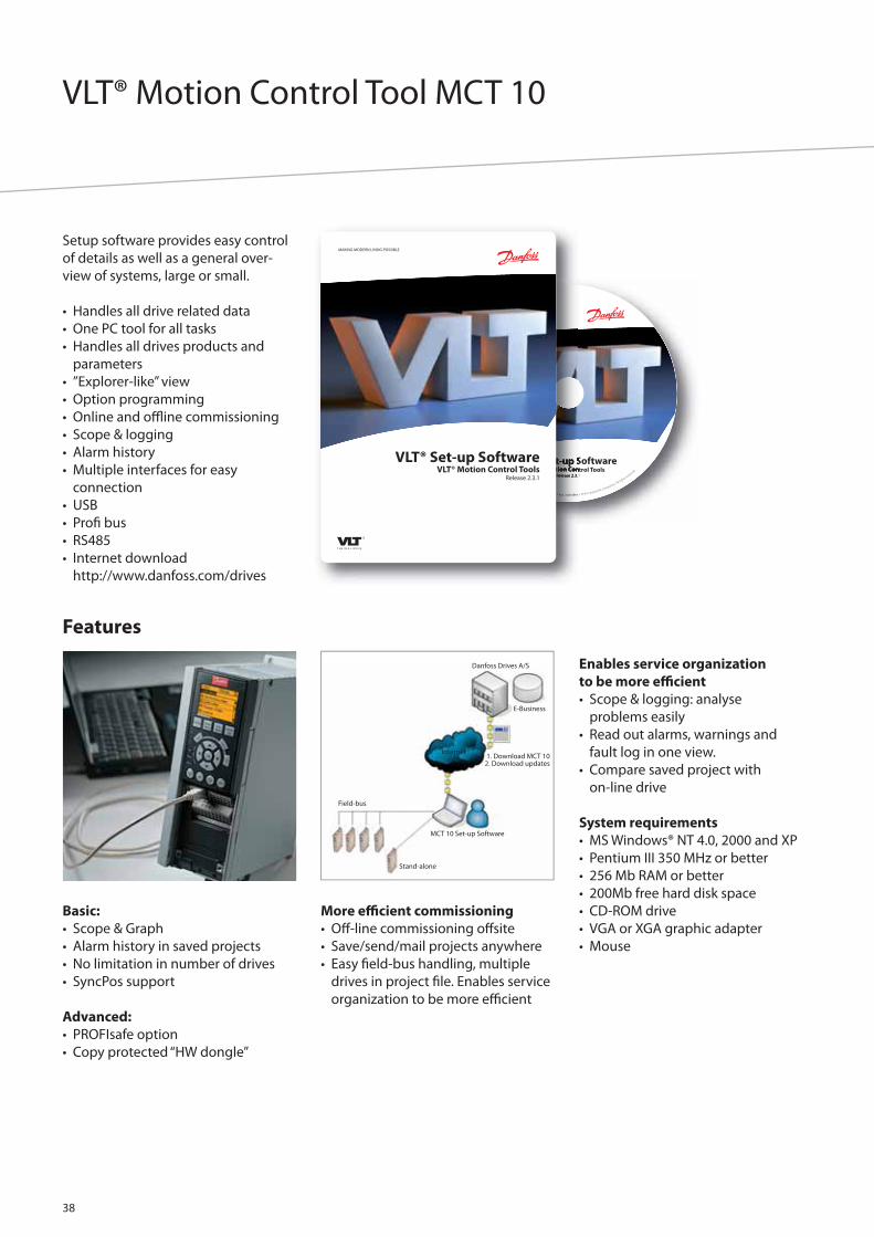
VLT® Motion Control Tool MCT 10
38
Basic:
• Scope & Graph
• Alarm history in saved projects
• No limitation in number of drives
• SyncPos support
Advanced:
• PROFIsafe option
• Copy protected “HW dongle”
More effi cient commissioning
• Off -line commissioning off site
• Save/send/mail projects anywhere
• Easy fi eld-bus handling, multiple
drives in project fi le. Enables service
organization to be more effi cient
Enables service organization
to be more effi cient
• Scope & logging: analyse
problems easily
• Read out alarms, warnings and
fault log in one view.
• Compare saved project with
on-line drive
System requirements
• MS Windows® NT 4.0, 2000 and XP
• Pentium III 350 MHz or better
• 256 Mb RAM or better
• 200Mb free hard disk space
• CD-ROM drive
• VGA or XGA graphic adapter
• Mouse
Features
Danfoss Drives A/S
E-Business
1. Download MCT 102. Download updates
Internet
Field-bus
Stand-alone
MCT 10 Set-up Software
VLT® Set-up SoftwareVLT® Motion Control Tools
Release 2.3.1© Danfoss A/S 2006-09 All trademarks in this material are property of the respective companies. A
ll rights r
eserved.
MAKING MODERN LIVING POSSIBLE
VLT® Set-up SoftwareVLT® Motion Control Tools
Release 2.3.1
Setup software provides easy control
of details as well as a general over-
view of systems, large or small.
• Handles all drive related data
• One PC tool for all tasks
• Handles all drives products and
parameters
• ”Explorer-like” view
• Option programming
• Online and offl ine commissioning
• Scope & logging
• Alarm history
• Multiple interfaces for easy
connection
• USB
• Profi bus
• RS485
• Internet download
http://www.danfoss.com/drives

VLT® Service – Your way
39
DriveProTM is an effi cient productivity
programme tailored to meet your
specifi c needs. All the necessary VLT®
Service facilities are at your disposal,
which will minimize downtime and
increase productivity at your factory.
This means that DriveProTM pays for
itself in no time.
DriveProTM service products are de-
signed to be customised and com-
bined.
Keep you running
Current drives update
The SmartStep service programme
ensures that Danfoss Products are
replaced before breakdown.
Commissioning and
regular adjustments
The mechanical condition of machin-
ery changes over time. Regular adjust-
ments can prevent failure messages
and production stops.
Preventive maintenance
Proactive maintenance gives you the
peace of mind that comes with know-
ing your drives have been properly
inspected and maintained.
Keep you fi t
Training
Specialised service courses enable
your own maintenance staff to carry
out troubleshooting and service.
Stock maintenance & consignment
The DriveProTM stock maintenance &
consignment programme provides
two variants of stock properties.
Danfoss ensures the best choice of
equipment is present at the stock.
Harmonic Survey
The DriveProTM Harmonic Survey
covers the installation of relevant
instruments, as well as analysis and
consultancy regarding actions to be
taken.
Environmentally sound disposal
Danfoss provides controlled environ-
mentally sound disposal of redundant
drives in line with local requirements.
Fix your costs
Fixed price
Stick to your drive repair budget.
Material, labour and transport
to a Danfoss lab are included.
Post-warranty agreement
After the 12-month factory warranty
expires, you can extend your warranty
up to 5 years.
Contact your local Danfoss offi ce
for an extended warranty.
Transport insurance
Danfoss takes full responsibility for
damage to drives in transit.
No complicated procedures.
A simple note, and Danfoss will fi x it.
Response time
Customised fast response service
night and day keeps processes run-
ning.
Danfoss Drives, Ulsnaes 1, DK-6300 Graasten, Denmark, Tel. +45 74 88 22 22, Fax +45 74 65 25 80, www.danfoss.com/drives • E-mail: [email protected]
DKDD.PB.101.A2.02 VLT® is a trademark of Danfoss A/S Produced by KKM 2006.11
Dedicated to drives
Dedication has been a key word since
1968, when Danfoss introduced the
world’s fi rst mass produced variable
speed drive for AC motors – and
named it VLT®.
Two thousand employees develop,
manufacture, sell and service drives
and softstarters in more than one
hundred countries, focused only on
drives and softstarters.
Intelligent and innovative
Developers at Danfoss Drives have
fully adopted modular principles in
development as well as design,
production and confi guration.
Tomorrow’s features are developed in
parallel using dedicated technology
platforms. This allows the develop-
ment of all elements to take place in
parallel, at the same time reducing
time to market and ensuring that
customers always enjoy the benefi ts
of the latest features.
Rely on the experts
We take responsibility for every
element in our products. The fact that
we develop and produce our own
features, hardware, software, power
modules, printed circuit boards, and
accessories is your guarantee for
reliable products.
Local backup – globally
VLT® motor controllers are operating
in applications all over the world and
Danfoss Drives’ experts located in
more than 100 countries are ready to
support our customers with applica-
tion advice and service wherever they
may be.
Danfoss Drives experts don’t stop un-
til the customer’s drive challenges are
solved.
Protects environment
VLT® products are manufactured with respect for both the physical and the social environments.
All activities are planned and per-formed taking into account the individual employee, the work environ-ment and the external environment. Production takes place without noise, smoke or other pollution and secure disposal of the products is assured.
UN Global CompactDanfoss has signed the UN Global Compact on social and environmental responsibility and our companies actresponsibly towards local societies.
EU Directives All factories are certifi ed according to ISO 14001 standard and fulfi l the EU Directives for General Product Safety (GPSD) and the Machinery directive. Danfoss Drives is in all product series implementing the EU Directive con-cerning Hazardous Substances in Elec-trical and Electrical Equipment (RoHS) and is designing all new product series according to the EU Directive on Waste Electrical and Electronic Equipment (WEEE).
Products impactOne year’s production of VLT® drives will save energy equivalent to the energy production of an atomic power plant. Better process control at the same time improves product quality and reduces waste and wear on equipment.
What VLT® is all aboutDanfoss Drives is the world leader among dedicated drives providers
– and still gaining market share.