General Control Principles – All Drives - VLT · 800.621.8806 G 3 Water & Wastewater Engineering...
31
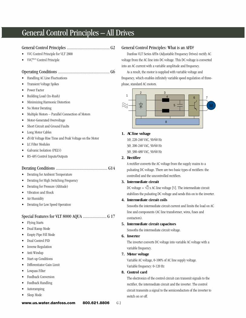
G 2 www.us.water.danfoss.com 800.621.8806 General Control Principles: What is an AFD? Danfoss VLT Series AFDs (Adjustable Frequency Drives) rectify AC voltage from the AC line into DC voltage. This DC voltage is converted into an AC current with a variable amplitude and frequency. As a result, the motor is supplied with variable voltage and frequency, which enables infinitely variable speed regulation of three- phase, standard AC motors. M 7 6 4 5 3 8 2 1 1. AC line voltage 1Ø, 220-240 VAC, 50/60 Hz 3Ø, 200-240 VAC, 50/60 Hz 3Ø, 380-480 VAC, 50/60 Hz 2. Rectifier A rectifier converts the AC voltage from the supply mains to a pulsating DC voltage. There are two basic types of rectifiers: the controlled and the uncontrolled rectifiers. 3. Intermediate circuit DC voltage = √2 x AC line voltage [V]. The intermediate circuit stabilizes the pulsating DC voltage and sends this on to the inverter. 4. Intermediate circuit coils Smooths the intermediate circuit current and limits the load on AC line and components (AC line transformer, wires, fuses and contactors). 5. Intermediate circuit capacitors Smooths the intermediate circuit voltage. 6. Inverter The inverter converts DC voltage into variable AC voltage with a variable frequency. 7. Motor voltage Variable AC voltage, 0-100% of AC line supply voltage. Variable frequency: 0-120 Hz 8. Control card The electronics of the control circuit can transmit signals to the rectifier, the intermediate circuit and the inverter. The control circuit transmits a signal to the semiconductors of the inverter to switch on or off. General Control Principles – All Drives General Control Principles ........................................ G2 • VVC Control Principle for VLT 2800 • VVC PLUS Control Principle Operating Conditions ................................................ G6 • Handling AC Line Fluctuations • Transient Voltage Spikes • Power Factor • Building Load (In-Rush) • Minimizing Harmonic Distortion • No Motor Derating • Multiple Motors – Parallel Connection of Motors • Motor-Generated Overvoltage • Short Circuit and Ground Faults • Long Motor Cables • dV/dt Voltage Rise Time and Peak Voltage on the Motor • LC Filter Modules • Galvanic Isolation (PELV) • RS-485 Control Inputs/Outputs Derating Conditions ................................................ G14 • Derating for Ambient Temperature • Derating for High Switching Frequency • Derating for Pressure (Altitude) • Vibration and Shock • Air Humidity • Derating for Low Speed Operation Special Features for VLT 8000 AQUA ...................... G 17 • Flying Starts • Dual Ramp Mode • Empty Pipe Fill Mode • Dual Control PID • Inverse Regulation • Anti Windup • Start-up Conditions • Differentiator Gain Limit • Lowpass Filter • Feedback Conversion • Feedback Handling • Autoramping • Sleep Mode
Transcript of General Control Principles – All Drives - VLT · 800.621.8806 G 3 Water & Wastewater Engineering...
G 2www.us.water.danfoss.com 800.621.8806
General Control Principles: What is an AFD?Danfoss VLT Series AFDs (Adjustable Frequency Drives) rectify AC
voltage from the AC line into DC voltage. This DC voltage is converted
into an AC current with a variable amplitude and frequency.
As a result, the motor is supplied with variable voltage and
frequency, which enables infinitely variable speed regulation of three-
phase, standard AC motors.
M
764
5
3
8
21
1. AC line voltage
1Ø, 220-240 VAC, 50/60 Hz
3Ø, 200-240 VAC, 50/60 Hz
3Ø, 380-480 VAC, 50/60 Hz
2. Rectifier
A rectifier converts the AC voltage from the supply mains to a
pulsating DC voltage. There are two basic types of rectifiers: the
controlled and the uncontrolled rectifiers.
3. Intermediate circuit
DC voltage = √2 x AC line voltage [V]. The intermediate circuit
stabilizes the pulsating DC voltage and sends this on to the inverter.
4. Intermediate circuit coils
Smooths the intermediate circuit current and limits the load on AC
line and components (AC line transformer, wires, fuses and
contactors).
5. Intermediate circuit capacitors
Smooths the intermediate circuit voltage.
6. Inverter
The inverter converts DC voltage into variable AC voltage with a
variable frequency.
7. Motor voltage
Variable AC voltage, 0-100% of AC line supply voltage.
Variable frequency: 0-120 Hz
8. Control card
The electronics of the control circuit can transmit signals to the
rectifier, the intermediate circuit and the inverter. The control
circuit transmits a signal to the semiconductors of the inverter to
switch on or off.
General Control Principles – All Drives
General Control Principles ........................................ G2• VVC Control Principle for VLT 2800
• VVCPLUS Control Principle
Operating Conditions ................................................ G6• Handling AC Line Fluctuations
• Transient Voltage Spikes
• Power Factor
• Building Load (In-Rush)
• Minimizing Harmonic Distortion
• No Motor Derating
• Multiple Motors – Parallel Connection of Motors
• Motor-Generated Overvoltage
• Short Circuit and Ground Faults
• Long Motor Cables
• dV/dt Voltage Rise Time and Peak Voltage on the Motor
• LC Filter Modules
• Galvanic Isolation (PELV)
• RS-485 Control Inputs/Outputs
Derating Conditions ................................................ G14• Derating for Ambient Temperature
• Derating for High Switching Frequency
• Derating for Pressure (Altitude)
• Vibration and Shock
• Air Humidity
• Derating for Low Speed Operation
Special Features for VLT 8000 AQUA ...................... G 17• Flying Starts
• Dual Ramp Mode
• Empty Pipe Fill Mode
• Dual Control PID
• Inverse Regulation
• Anti Windup
• Start-up Conditions
• Differentiator Gain Limit
• Lowpass Filter
• Feedback Conversion
• Feedback Handling
• Autoramping
• Sleep Mode
G 3 Water & Wastewaterwww.us.water.danfoss.com 800.621.8806
En
gin
eerin
g R
efe
ren
ce
G
General Control Principles – VLT® 2800
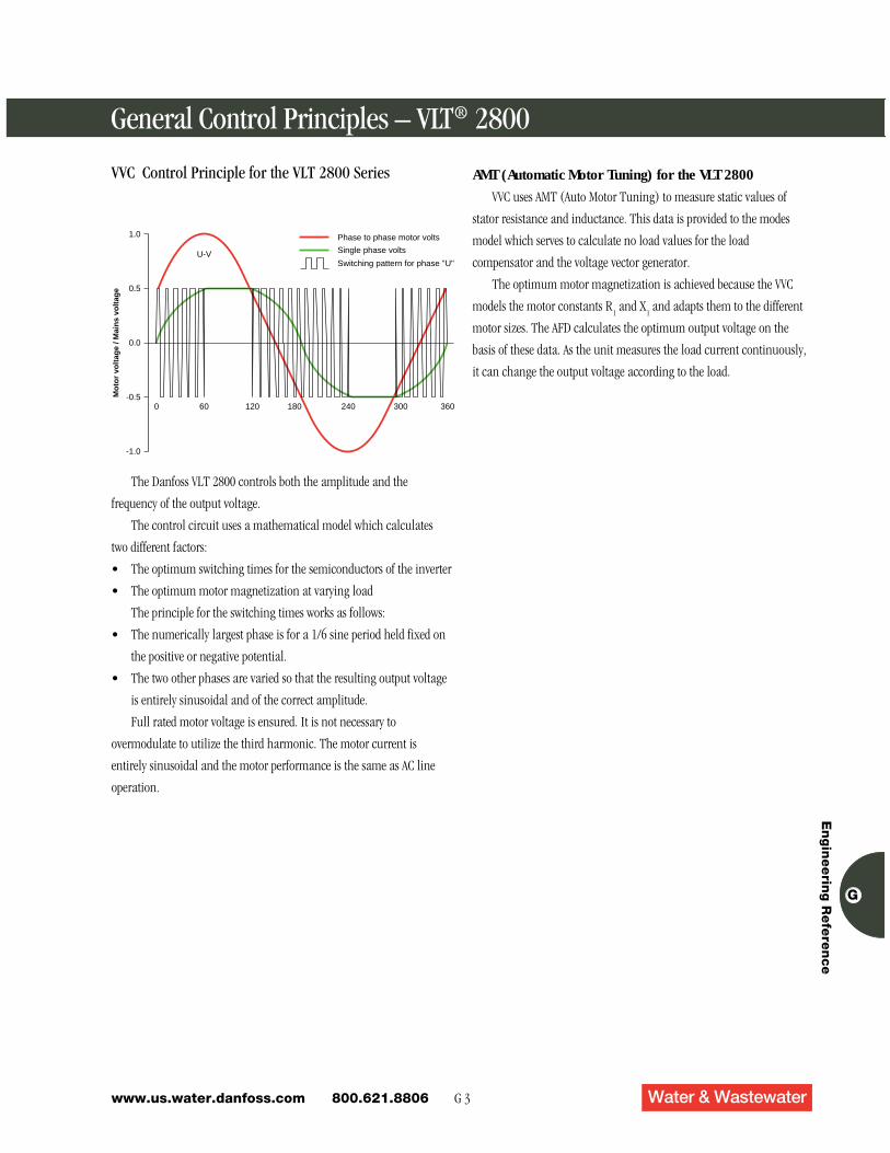
The Danfoss VLT 2800 controls both the amplitude and the
frequency of the output voltage.
The control circuit uses a mathematical model which calculates
two different factors:
• The optimum switching times for the semiconductors of the inverter
• The optimum motor magnetization at varying load
The principle for the switching times works as follows:
• The numerically largest phase is for a 1/6 sine period held fixed on
the positive or negative potential.
• The two other phases are varied so that the resulting output voltage
is entirely sinusoidal and of the correct amplitude.
Full rated motor voltage is ensured. It is not necessary to
overmodulate to utilize the third harmonic. The motor current is
entirely sinusoidal and the motor performance is the same as AC line
operation.
1.0
0.5
0.0
-0.5
-1.0
U-V
Mo
tor
volt
age
/ Mai
ns
volt
age
0 60 120 180 240 300 360
Switching pattern for phase "U"
Single phase volts
Phase to phase motor volts
VVC Control Principle for the VLT 2800 Series AMT (Automatic Motor Tuning) for the VLT 2800
VVC uses AMT (Auto Motor Tuning) to measure static values of
stator resistance and inductance. This data is provided to the modes
model which serves to calculate no load values for the load
compensator and the voltage vector generator.
The optimum motor magnetization is achieved because the VVC
models the motor constants R1 and X
1 and adapts them to the different
motor sizes. The AFD calculates the optimum output voltage on the
basis of these data. As the unit measures the load current continuously,
it can change the output voltage according to the load.
G 4www.us.water.danfoss.com 800.621.8806
VVCPLUS Control Principle for the VLT 8000 AQUA andVLT 5000 Series
VLT 8000 AQUA Series features an inverter control system called
VVCPLUS, which is a further development of the VVC (Voltage Vector
Control) from the Danfoss VLT Series 2800.
Danfoss Voltage Vector Control technology uses exclusive digital
techniques and a 32-bit microprocessor to generate motor currents that
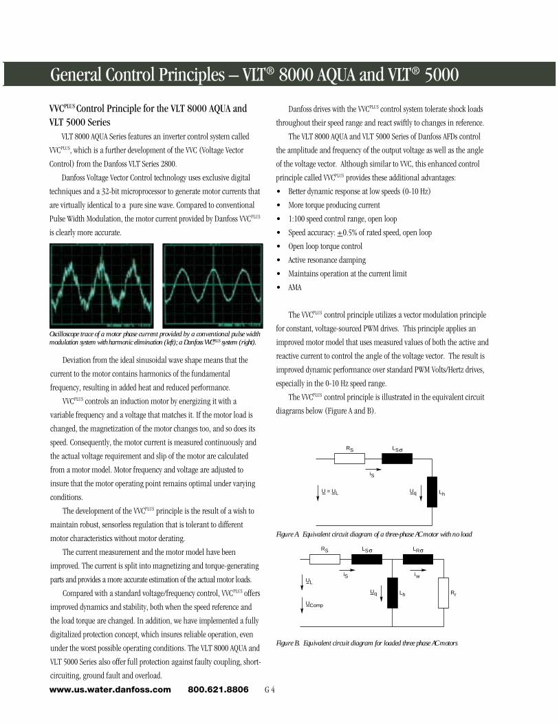
are virtually identical to a pure sine wave. Compared to conventional
Pulse Width Modulation, the motor current provided by Danfoss VVCPLUS
is clearly more accurate.
Oscilloscope trace of a motor phase current provided by a conventional pulse widthmodulation system with harmonic elimination (left); a Danfoss VVCPLUS system (right).
Deviation from the ideal sinusoidal wave shape means that the
current to the motor contains harmonics of the fundamental
frequency, resulting in added heat and reduced performance.
VVCPLUS controls an induction motor by energizing it with a
variable frequency and a voltage that matches it. If the motor load is
changed, the magnetization of the motor changes too, and so does its
speed. Consequently, the motor current is measured continuously and
the actual voltage requirement and slip of the motor are calculated
from a motor model. Motor frequency and voltage are adjusted to
insure that the motor operating point remains optimal under varying
conditions.
The development of the VVCPLUS principle is the result of a wish to
maintain robust, sensorless regulation that is tolerant to different
motor characteristics without motor derating.
The current measurement and the motor model have been
improved. The current is split into magnetizing and torque-generating
parts and provides a more accurate estimation of the actual motor loads.
Compared with a standard voltage/frequency control, VVCPLUS offers
improved dynamics and stability, both when the speed reference and
the load torque are changed. In addition, we have implemented a fully
digitalized protection concept, which insures reliable operation, even
under the worst possible operating conditions. The VLT 8000 AQUA and
VLT 5000 Series also offer full protection against faulty coupling, short-
circuiting, ground fault and overload.
General Control Principles – VLT® 8000 AQUA and VLT® 5000
Danfoss drives with the VVCPLUS control system tolerate shock loads
throughout their speed range and react swiftly to changes in reference.
The VLT 8000 AQUA and VLT 5000 Series of Danfoss AFDs control
the amplitude and frequency of the output voltage as well as the angle
of the voltage vector. Although similar to VVC, this enhanced control
principle called VVCPLUS provides these additional advantages:
• Better dynamic response at low speeds (0-10 Hz)
• More torque producing current
• 1:100 speed control range, open loop
• Speed accuracy: +0.5% of rated speed, open loop
• Open loop torque control
• Active resonance damping
• Maintains operation at the current limit
• AMA
The VVCPLUS control principle utilizes a vector modulation principle
for constant, voltage-sourced PWM drives. This principle applies an
improved motor model that uses measured values of both the active and
reactive current to control the angle of the voltage vector. The result is
improved dynamic performance over standard PWM Volts/Hertz drives,
especially in the 0-10 Hz speed range.
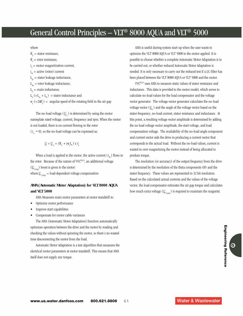
The VVCPLUS control principle is illustrated in the equivalent circuit
diagrams below (Figure A and B).
Figure A. Equivalent circuit diagram of a three-phase AC motor with no load
Figure B. Equivalent circuit diagram for loaded three phase AC motors
RS LS
LhUqU = UL
iS
RS LS
LhUq
UComp
iS
LR
Rr
iwUL
G 5 Water & Wastewaterwww.us.water.danfoss.com 800.621.8806
En
gin
eerin
g R
efe
ren
ce
G
where
RS = stator resistance,
Rr = rotor resistance,
iS = motor magnetization current,
iW = active (rotor) current
LSs
= stator leakage inductance,
LRs
= rotor leakage inductance,
Lh = main inductance,
LS (=L
Ss + L
h) = stator inductance and
ws (=2πf
s) = angular speed of the rotating field in the air gap
The no-load voltage ( UL) is determined by using the motor
nameplate rated voltage, current, frequency and rpm. When the motor
is not loaded, there is no current flowing in the rotor
( iw = 0), so the no-load voltage can be expressed as:
U = UL = (R
S + jw
sL
S) x i
s
When a load is applied to the motor, the active current ( iW
) flows in
the rotor. Because of the nature of VVCPLUS, an additional voltage
(UComp
) boost is given to the motor:
where UComp
= load-dependent voltage compensation
AMA (Automatic Motor Adaptation) for VLT 8000 AQUA
and VLT 5000
AMA Measures main motor parameters at motor standstill to:
• Optimize motor performance
• Improve start capabilities
• Compensate for motor cable variances
The AMA (Automatic Motor Adaptation) function automatically
optimizes operation between the drive and the motor by reading and
checking the values without spinning the motor, so there’s no wasted
time disconnecting the motor from the load.
Automatic Motor Adaptation is a test algorithm that measures the
electrical motor parameters at motor standstill. This means that AMA
itself does not supply any torque.
General Control Principles – VLT® 8000 AQUA and VLT® 5000
AMA is useful during system start-up when the user wants to
optimize the VLT 8000 AQUA or VLT 5000 to the motor applied. It is
possible to choose whether a complete Automatic Motor Adaptation is to
be carried out, or whether reduced Automatic Motor Adaptation is
needed. It is only necessary to carry out the reduced test if a LC-filter has
been placed between the VLT 8000 AQUA or VLT 5000 and the motor.
VVCPLUS uses AMA to measure static values of stator resistance and
inductance. This data is provided to the motor model, which serves to
calculate no-load values for the load compensator and the voltage
vector generator. The voltage vector generator calculates the no-load
voltage vector (UL) and the angle of the voltage vector based on the
stator frequency, no-load current, stator resistance and inductance. At
this point, a resulting voltage vector amplitude is determined by adding
the no load voltage vector amplitude, the start voltage, and load
compensation voltage. The availability of the no-load angle component
and current vector aids the drive in producing a current vector that
corresponds to the actual load. Without the no-load values, current is
wasted in over-magnetizing the motor instead of being allocated to
produce torque.
The resolution (or accuracy) of the output frequency from the drive
is determined by the resolution of the theta components (Ø) and the
stator frequency. These values are represented in 32 bit resolution.
Based on the calculated actual currents and the values of the voltage
vector, the load compensator estimates the air gap torque and calculates
how much extra voltage ( U Comp
) is required to maintain the magnetic
G 6www.us.water.danfoss.com 800.621.8806
L1
L2
L3
L1
L2
L3
PE
VLT SeriesRFIAC Line
RFIHandling AC Line FluctuationsEvery manufacturing facility experiences fluctuations in the AC
line. With a Danfoss drive, these fluctuations do not pose any hazard to
the drive and will not cause speed or torque variations in the
application. Danfoss drives compensate for AC line fluctuations so that
the motor shaft’s actual torque is constant.
To protect itself from AC line fluctuations, a monitor of the AC line
phases interrupts the drive if there is a loss of phase or if there is a
significant difference between phases.
Transient Voltage SpikesMost industrial AC lines are disturbed by line transients which can
be short overvoltages of up to 1000 VAC. They arise when high loads are
cut in and out elsewhere on the AC line. A lightning strike directly to the
supply wire is another common cause of transient high voltage. The
transient may damage installations at distances up to four miles from
where the lightning strikes. Short circuits in the supply lines can also
cause transients. High currents due to short circuits can result in very
high voltage in the surrounding cables because of inductive coupling.
VLT Series drives are built to a stringent German specification for surge
suppression (VDE 160). Fast acting MOVs, Zener diodes and oversized
DC link filter provide protection against high potential spikes. The VLT
Series drives can withstand a spike of 2.3 times the rated voltage for 1.3
msec.
Power FactorVLT Series drives hold near unity power factor at all loads and
speeds, and eliminate the need for power factor correction, resulting in
both financial and space savings.
The power factor is the relation between I1and I
RMS. The power
factor indicates the extent to which the drive imposes a load on the AC
line supply.
The lower the power factor, the higher the I RMS
for the same kW
performance.
In addition, a high power factor indicates that the different
harmonic currents are low.
Operating Conditions – All Drives
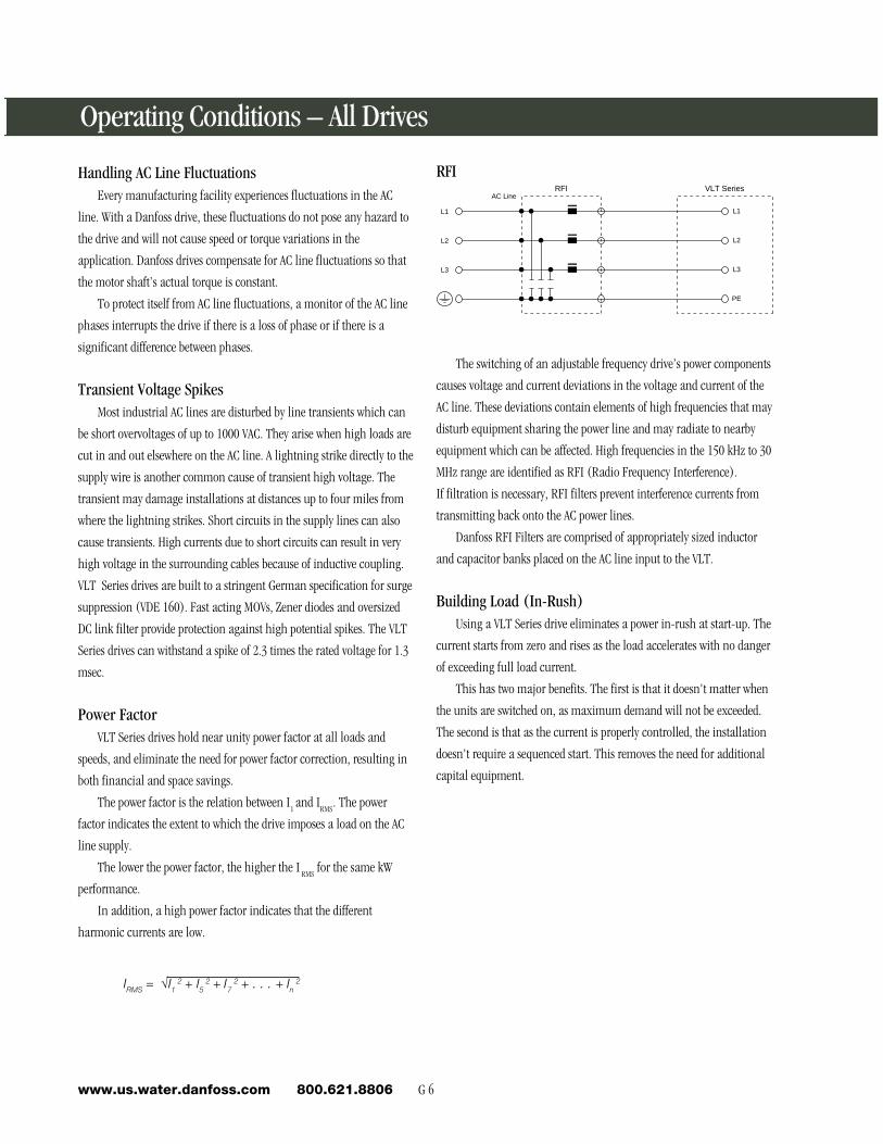
The switching of an adjustable frequency drive’s power components
causes voltage and current deviations in the voltage and current of the
AC line. These deviations contain elements of high frequencies that may
disturb equipment sharing the power line and may radiate to nearby
equipment which can be affected. High frequencies in the 150 kHz to 30
MHz range are identified as RFI (Radio Frequency Interference).
If filtration is necessary, RFI filters prevent interference currents from
transmitting back onto the AC power lines.
Danfoss RFI Filters are comprised of appropriately sized inductor
and capacitor banks placed on the AC line input to the VLT.
Building Load (In-Rush)Using a VLT Series drive eliminates a power in-rush at start-up. The
current starts from zero and rises as the load accelerates with no danger
of exceeding full load current.
This has two major benefits. The first is that it doesn't matter when
the units are switched on, as maximum demand will not be exceeded.
The second is that as the current is properly controlled, the installation
doesn't require a sequenced start. This removes the need for additional
capital equipment.
IRMS = √I12 + I5
2 + I72 + . . . + In
2
G 7 Water & Wastewaterwww.us.water.danfoss.com 800.621.8806
En
gin
eerin
g R
efe
ren
ce
G
Minimizing Harmonic DistortionDanfoss harmonic currents are lower than other drive designs, and
therefore, provide the lowest voltage distortion and offer less chance of
disturbing other equipment.
The built-in DC link filters in the VLT drives reduces the harmonic
distortion currents that it injects back into the AC line. A properly sized
inductor, such as that in our VLT drives can reduce line harmonic
currents to 40% or less of the fundamental current without the use of AC
line inductors and their resultant line voltage reduction.
The added heat generated by harmonic currents requires larger
conductors and transformers for the same amount of delivered energy,
therefore, increasing the cost of the installation. Other sources of
harmonic current distortion include fluorescent lights, computers, UPS
systems, copiers, printers, induction heaters, and battery chargers. Many
of these nonlinear loads are not only the source of harmonic distortion,
but are also adversely affected by harmonic distortion as well.
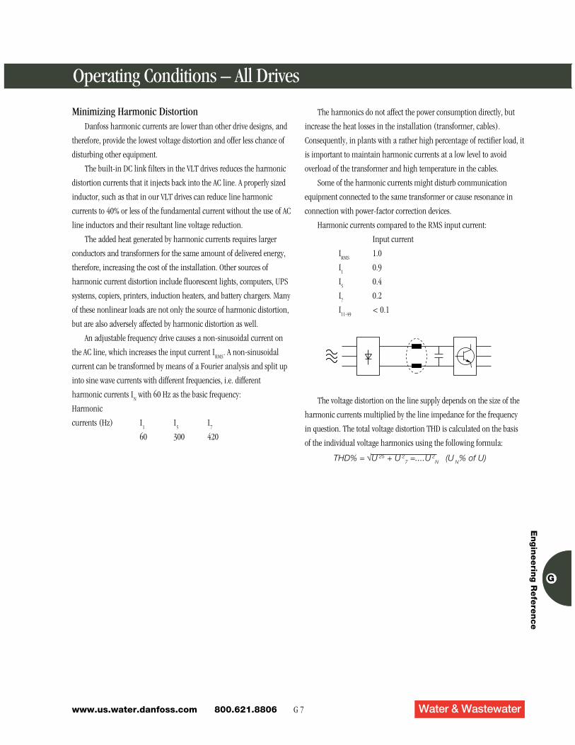
An adjustable frequency drive causes a non-sinusoidal current on
the AC line, which increases the input current IRMS
. A non-sinusoidal
current can be transformed by means of a Fourier analysis and split up
into sine wave currents with different frequencies, i.e. different
harmonic currents IN with 60 Hz as the basic frequency:
Harmonic
currents (Hz) I1
I5
I7
60 300 420
THD% = √U 25 + U 27 =....U 2
N (U N% of U)
The voltage distortion on the line supply depends on the size of the
harmonic currents multiplied by the line impedance for the frequency
in question. The total voltage distortion THD is calculated on the basis
of the individual voltage harmonics using the following formula:
Operating Conditions – All Drives
The harmonics do not affect the power consumption directly, but
increase the heat losses in the installation (transformer, cables).
Consequently, in plants with a rather high percentage of rectifier load, it
is important to maintain harmonic currents at a low level to avoid
overload of the transformer and high temperature in the cables.
Some of the harmonic currents might disturb communication
equipment connected to the same transformer or cause resonance in
connection with power-factor correction devices.
Harmonic currents compared to the RMS input current:
Input current
IRMS
1.0
I1
0.9
I5
0.4
I7
0.2
I11-49
< 0.1
G 8www.us.water.danfoss.com 800.621.8806
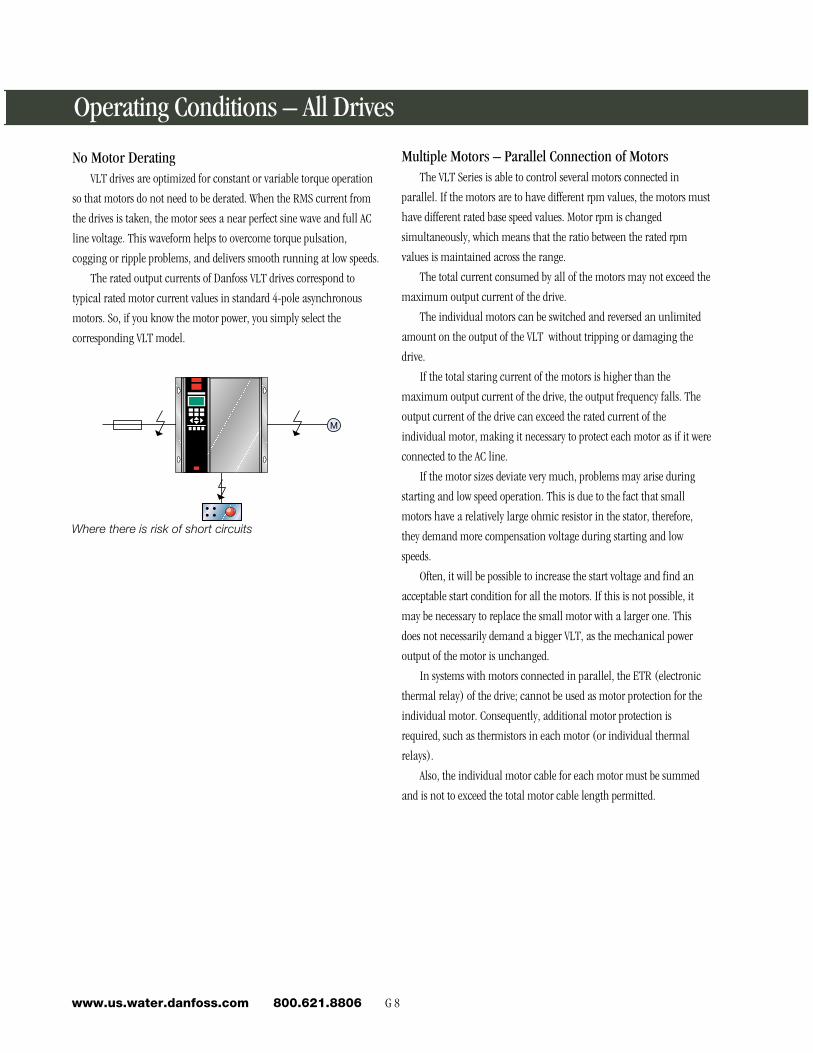
No Motor DeratingVLT drives are optimized for constant or variable torque operation
so that motors do not need to be derated. When the RMS current from
the drives is taken, the motor sees a near perfect sine wave and full AC
line voltage. This waveform helps to overcome torque pulsation,
cogging or ripple problems, and delivers smooth running at low speeds.
The rated output currents of Danfoss VLT drives correspond to
typical rated motor current values in standard 4-pole asynchronous
motors. So, if you know the motor power, you simply select the
corresponding VLT model.
M
Where there is risk of short circuits
Operating Conditions – All Drives
Multiple Motors – Parallel Connection of MotorsThe VLT Series is able to control several motors connected in
parallel. If the motors are to have different rpm values, the motors must
have different rated base speed values. Motor rpm is changed
simultaneously, which means that the ratio between the rated rpm
values is maintained across the range.
The total current consumed by all of the motors may not exceed the
maximum output current of the drive.
The individual motors can be switched and reversed an unlimited
amount on the output of the VLT without tripping or damaging the
drive.
If the total staring current of the motors is higher than the
maximum output current of the drive, the output frequency falls. The
output current of the drive can exceed the rated current of the
individual motor, making it necessary to protect each motor as if it were
connected to the AC line.
If the motor sizes deviate very much, problems may arise during
starting and low speed operation. This is due to the fact that small
motors have a relatively large ohmic resistor in the stator, therefore,
they demand more compensation voltage during starting and low
speeds.
Often, it will be possible to increase the start voltage and find an
acceptable start condition for all the motors. If this is not possible, it
may be necessary to replace the small motor with a larger one. This
does not necessarily demand a bigger VLT, as the mechanical power
output of the motor is unchanged.
In systems with motors connected in parallel, the ETR (electronic
thermal relay) of the drive; cannot be used as motor protection for the
individual motor. Consequently, additional motor protection is
required, such as thermistors in each motor (or individual thermal
relays).
Also, the individual motor cable for each motor must be summed
and is not to exceed the total motor cable length permitted.
G 9 Water & Wastewaterwww.us.water.danfoss.com 800.621.8806
En
gin
eerin
g R
efe
ren
ce
G
Operating Conditions – All Drives
Star Delta
20 30 40 50 600
Po
wer
%
Motor Frequency Hz
100
200
300
400
500
600
700
800
Direct-on-Line
VLT 5000
Soft Starter
Starting Currents
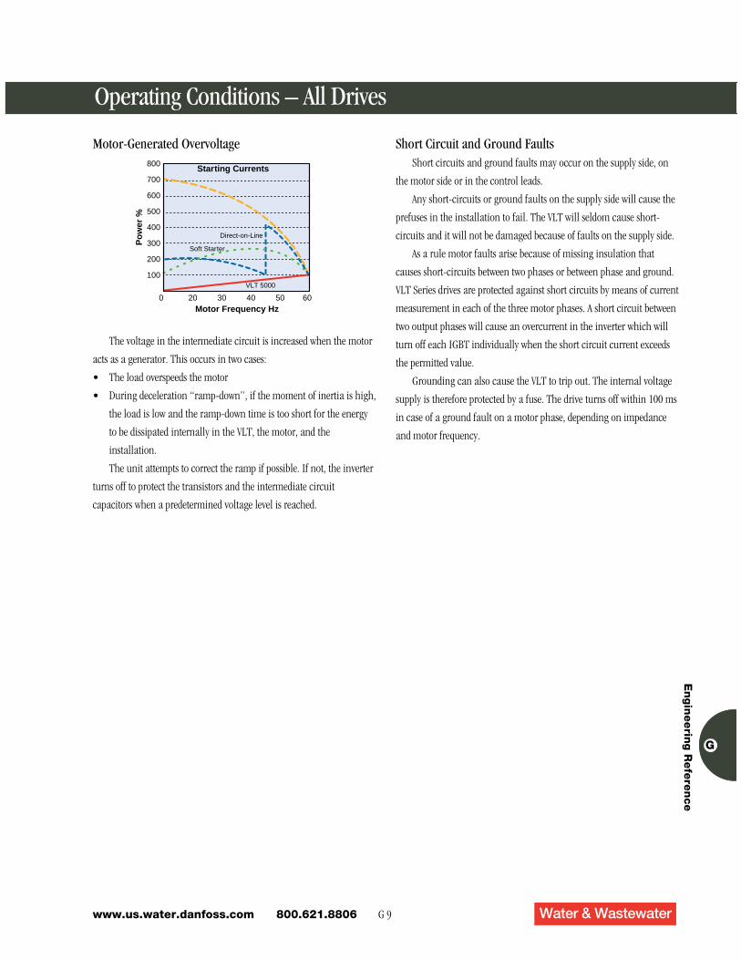
Motor-Generated Overvoltage
The voltage in the intermediate circuit is increased when the motor
acts as a generator. This occurs in two cases:
• The load overspeeds the motor
• During deceleration “ramp-down”, if the moment of inertia is high,
the load is low and the ramp-down time is too short for the energy
to be dissipated internally in the VLT, the motor, and the
installation.
The unit attempts to correct the ramp if possible. If not, the inverter
turns off to protect the transistors and the intermediate circuit
capacitors when a predetermined voltage level is reached.
Short Circuit and Ground FaultsShort circuits and ground faults may occur on the supply side, on
the motor side or in the control leads.
Any short-circuits or ground faults on the supply side will cause the
prefuses in the installation to fail. The VLT will seldom cause short-
circuits and it will not be damaged because of faults on the supply side.
As a rule motor faults arise because of missing insulation that
causes short-circuits between two phases or between phase and ground.
VLT Series drives are protected against short circuits by means of current
measurement in each of the three motor phases. A short circuit between
two output phases will cause an overcurrent in the inverter which will
turn off each IGBT individually when the short circuit current exceeds
the permitted value.
Grounding can also cause the VLT to trip out. The internal voltage
supply is therefore protected by a fuse. The drive turns off within 100 ms
in case of a ground fault on a motor phase, depending on impedance
and motor frequency.
G 10www.us.water.danfoss.com 800.621.8806
Operating Conditions – All Drives
dV/dt Voltage Rise Time and Peak Voltage on the MotorVoltage rise time is the amount of time for a voltage pulse at the
motor to go from 10% to 90% of the DC bus voltage. The rise time is
determined by:
• Switching speed of the inverter’s power components
• Motor leads (type, size, length and shielding)
• Inductors or filters wired between the drive and motor
Peak voltage is the maximum voltage that will be applied to the
motor windings. Self-inductance of the motor’s stator windings causes
an instantaneous voltage overshoot when an electrical pulse is applied
to the motor. The voltage level at this instantaneous overshoot is the
peak voltage. The peak voltage is determined by:
• Rise time of the pulse
• DC bus voltage
Motor insulation is stressed by both excessively short rise time and
high peak voltages. Motors without phase coil insulation are especially
susceptible to damage. If motors without phase coil insulation must be
used, or if lead lengths are long, an output inductor or LC filter should
be added to the drive.
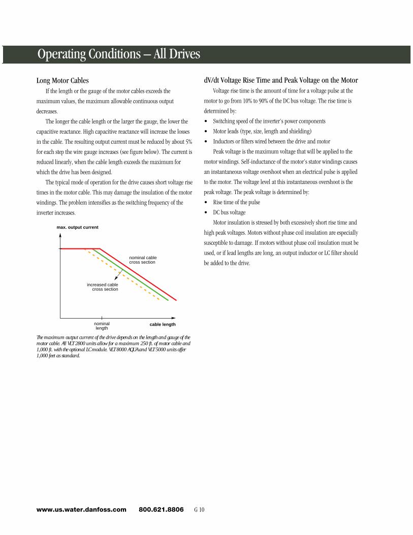
Long Motor CablesIf the length or the gauge of the motor cables exceeds the
maximum values, the maximum allowable continuous output
decreases.
The longer the cable length or the larger the gauge, the lower the
capacitive reactance. High capacitive reactance will increase the losses
in the cable. The resulting output current must be reduced by about 5%
for each step the wire gauge increases (see figure below). The current is
reduced linearly, when the cable length exceeds the maximum for
which the drive has been designed.
The typical mode of operation for the drive causes short voltage rise
times in the motor cable. This may damage the insulation of the motor
windings. The problem intensifies as the switching frequency of the
inverter increases.
The maximum output current of the drive depends on the length and gauge of themotor cable. All VLT 2800 units allow for a maximum 250 ft. of motor cable and1,000 ft. with the optional LC module. VLT 8000 AQUA and VLT 5000 units offer1,000 feet as standard.
cable length
max. output current
nominallength
nominal cablecross section
increased cablecross section
G 11 Water & Wastewaterwww.us.water.danfoss.com 800.621.8806
En
gin
eerin
g R
efe
ren
ce
G
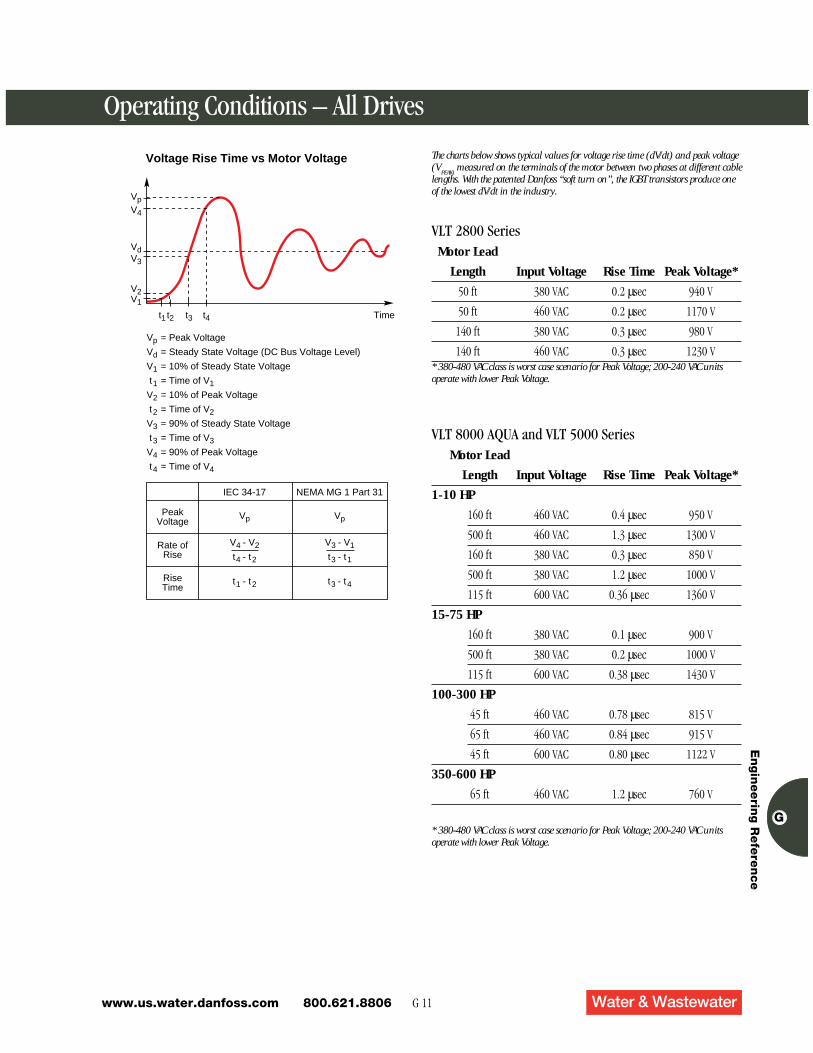
The charts below shows typical values for voltage rise time (dV/dt) and peak voltage(V
PEAK) measured on the terminals of the motor between two phases at different cable
lengths. With the patented Danfoss “soft turn on”, the IGBT transistors produce oneof the lowest dV/dt in the industry.
VLT 2800 SeriesMotor Lead
Length Input Voltage Rise Time Peak Voltage*
50 ft 380 VAC 0.2 µsec 940 V
50 ft 460 VAC 0.2 µsec 1170 V
140 ft 380 VAC 0.3 µsec 980 V
140 ft 460 VAC 0.3 µsec 1230 V* 380-480 VAC class is worst case scenario for Peak Voltage; 200-240 VAC unitsoperate with lower Peak Voltage.
VLT 8000 AQUA and VLT 5000 SeriesMotor Lead
Length Input Voltage Rise Time Peak Voltage*
1-10 HP
160 ft 460 VAC 0.4 µsec 950 V
500 ft 460 VAC 1.3 µsec 1300 V
160 ft 380 VAC 0.3 µsec 850 V
500 ft 380 VAC 1.2 µsec 1000 V
115 ft 600 VAC 0.36 µsec 1360 V
15-75 HP
160 ft 380 VAC 0.1 µsec 900 V
500 ft 380 VAC 0.2 µsec 1000 V
115 ft 600 VAC 0.38 µsec 1430 V
100-300 HP
45 ft 460 VAC 0.78 µsec 815 V
65 ft 460 VAC 0.84 µsec 915 V
45 ft 600 VAC 0.80 µsec 1122 V
350-600 HP
65 ft 460 VAC 1.2 µsec 760 V
Operating Conditions – All Drives
t4 Timet3t2t1
V1
Vp
Vd
V1
t1
V2
t2
V3
t3
V4
t4
= Peak Voltage
= Steady State Voltage (DC Bus Voltage Level)
= 10% of Steady State Voltage
= Time of V1
= 10% of Peak Voltage
= Time of V2
= 90% of Steady State Voltage
= Time of V3
= 90% of Peak Voltage
= Time of V4
PeakVoltage
Vp
IEC 34-17 NEMA MG 1 Part 31
Rate ofRise
RiseTime
V2
V3
Vd
V4
Vp
Voltage Rise Time vs Motor Voltage
Vp
t1 - t2 t3 - t4
V4 - V2
t4 - t2
V3 - V1
t3 - t1
* 380-480 VAC class is worst case scenario for Peak Voltage; 200-240 VAC unitsoperate with lower Peak Voltage.
G 12www.us.water.danfoss.com 800.621.8806
Operating Conditions – All Drives
Galvanic Isolation (PELV)All analog and digital inputs and outputs and the RS 485 serial
communication port are galvanically isolated from the supply
voltage. Because these points do not share a common, the drive can
eliminate ground loop problems.
In the VLT Series, all control terminals as well as terminals 1-5
(AUX relays) are supplied by or connected to circuits that comply with
PELV (high impedance) requirements in relation to the AC line
potential.
PELV offers protection by way of extra low voltage. Protection
against electric shock is considered to be ensured when the electrical
supply is of the PELV type and the installation is made as described in
local/national regulations on PELV supplies.
In VLT units, all control terminals as well as terminals 1-3 (AUX
relay) are supplied from or in connection with extra low voltage
(PELV).
Galvanic (ensured) isolation is obtained by fulfilling requirements
concerning higher isolation and by providing the relevant creepage/
clearance distances. These requirements are described in the EN 50178
standard.
The components that make up the electrical isolation, as described
below, also comply with the requirements concerning higher isolation
and the relevant test as described in EN 50178. The galvanic isolation
can be shown in three locations (see drawing below), namely:
1. Power supply (SMPS) including signal isolation of VDC indicating
the intermediate current voltage.
2. Gate drive that runs the IGBTs (trigger transformers/opto-couplers).
3. Current transducers (Hall effect current transducers).
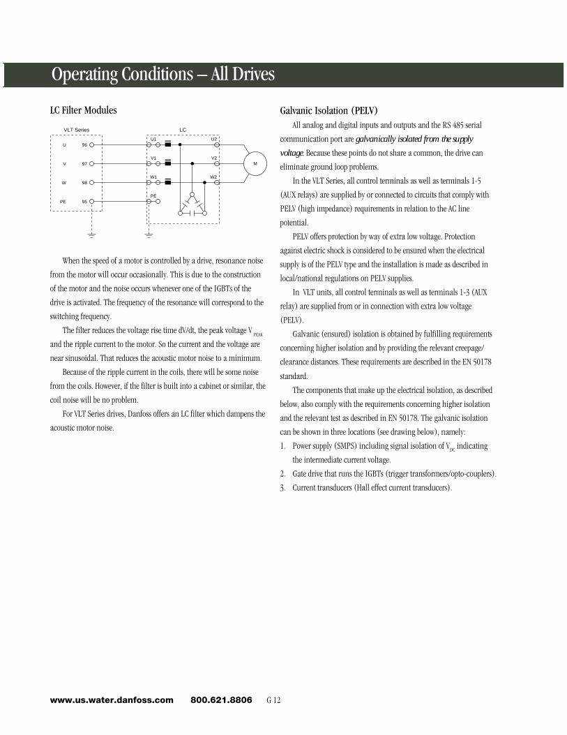
LC Filter Modules
96
97
98
LCVLT Series
U2
V2
W2
95
U
V
W
PE
M
U1
V1
W1
PE
When the speed of a motor is controlled by a drive, resonance noise
from the motor will occur occasionally. This is due to the construction
of the motor and the noise occurs whenever one of the IGBTs of the
drive is activated. The frequency of the resonance will correspond to the
switching frequency.
The filter reduces the voltage rise time dV/dt, the peak voltage V PEAK
and the ripple current to the motor. So the current and the voltage are
near sinusoidal. That reduces the acoustic motor noise to a minimum.
Because of the ripple current in the coils, there will be some noise
from the coils. However, if the filter is built into a cabinet or similar, the
coil noise will be no problem.
For VLT Series drives, Danfoss offers an LC filter which dampens the
acoustic motor noise.
G 13 Water & Wastewaterwww.us.water.danfoss.com 800.621.8806
En
gin
eerin
g R
efe
ren
ce
G
Operating Conditions – All Drives
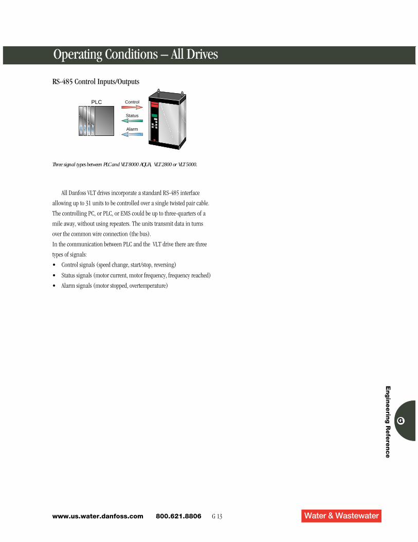
RS-485 Control Inputs/Outputs
Three signal types between PLC and VLT 8000 AQUA, VLT 2800 or VLT 5000.
PLC
Status
Control
Alarm
All Danfoss VLT drives incorporate a standard RS-485 interface
allowing up to 31 units to be controlled over a single twisted pair cable.
The controlling PC, or PLC, or EMS could be up to three-quarters of a
mile away, without using repeaters. The units transmit data in turns
over the common wire connection (the bus).
In the communication between PLC and the VLT drive there are three
types of signals:
• Control signals (speed change, start/stop, reversing)
• Status signals (motor current, motor frequency, frequency reached)
• Alarm signals (motor stopped, overtemperature)
G 14www.us.water.danfoss.com 800.621.8806
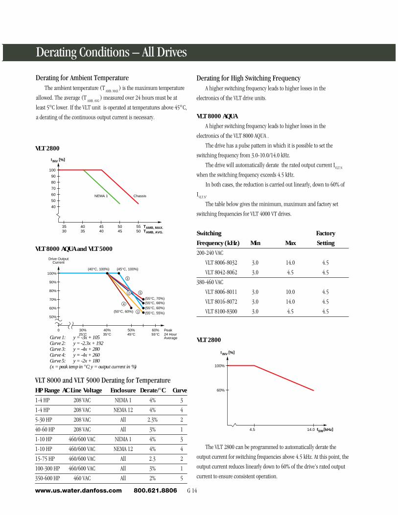
Derating for High Switching FrequencyA higher switching frequency leads to higher losses in the
electronics of the VLT drive units.
VLT 8000 AQUA
A higher switching frequency leads to higher losses in the
electronics of the VLT 8000 AQUA .
The drive has a pulse pattern in which it is possible to set the
switching frequency from 3.0-10.0/14.0 kHz.
The drive will automatically derate the rated output current IVLT.N
when the switching frequency exceeds 4.5 kHz.
In both cases, the reduction is carried out linearly, down to 60% of
IVLT.N.
The table below gives the minimum, maximum and factory set
switching frequencies for VLT 4000 VT drives.
Switching Factory
Frequency (kHz) Min Max Setting
200-240 VAC
VLT 8006-8032 3.0 14.0 4.5
VLT 8042-8062 3.0 4.5 4.5
380-460 VAC
VLT 8006-8011 3.0 10.0 4.5
VLT 8016-8072 3.0 14.0 4.5
VLT 8100-8300 3.0 4.5 4.5
Derating Conditions – All Drives
Derating for Ambient TemperatureThe ambient temperature (T
AMB. MAX ) is the maximum temperature
allowed. The average (T AMB. AVG
) measured over 24 hours must be at
least 5°C lower. If the VLT unit is operated at temperatures above 45°C,
a derating of the continuous output current is necessary.
100
I INV [%]
3530
5045
4035
4540
5550
90
80
70
60
50
40
TAMB, MAX.TAMB, AVG.
NEMA 1 Chassis
VLT 2800
VLT 8000 AQUA and VLT 5000
VLT 2800
100%
60%
14.0 fSW[kHz]
I INV [%]
4.5
(55°C, 70%)
(45°C, 100%)(40°C, 100%)
(55°C, 66%)(55°C, 60%)(55°C, 55%)(50°C, 60%)
2
3
5
4
1
0 30% 25°C
40%35°C
50%45°C
60%55°C
50%
60%
70%
80%
90%
100%
Peak24 HourAverage
Drive OutputCurrent
VLT 8000 and VLT 5000 Derating for TemperatureHP Range AC Line Voltage Enclosure Derate/°C Curve
1-4 HP 208 VAC NEMA 1 4% 3
1-4 HP 208 VAC NEMA 12 4% 4
5-30 HP 208 VAC All 2.3% 2
40-60 HP 208 VAC All 3% 1
1-10 HP 460/600 VAC NEMA 1 4% 3
1-10 HP 460/600 VAC NEMA 12 4% 4
15-75 HP 460/600 VAC All 2.3 2
100-300 HP 460/600 VAC All 3% 1
350-600 HP 460 VAC All 2% 5
Curve 1: y = -3x + 105Curve 2: y = -2.3x + 192Curve 3: y = -4x + 280Curve 4: y = -4x + 260Curve 5: y = -2x + 180(x = peak temp in °C; y = output current in %)
The VLT 2800 can be programmed to automatically derate the
output current for switching frequencies above 4.5 kHz. At this point, the
output current reduces linearly down to 60% of the drive's rated output
current to ensure consistent operation.
G 15 Water & Wastewaterwww.us.water.danfoss.com 800.621.8806
En
gin
eerin
g R
efe
ren
ce
G
Derating Conditions – All Drives
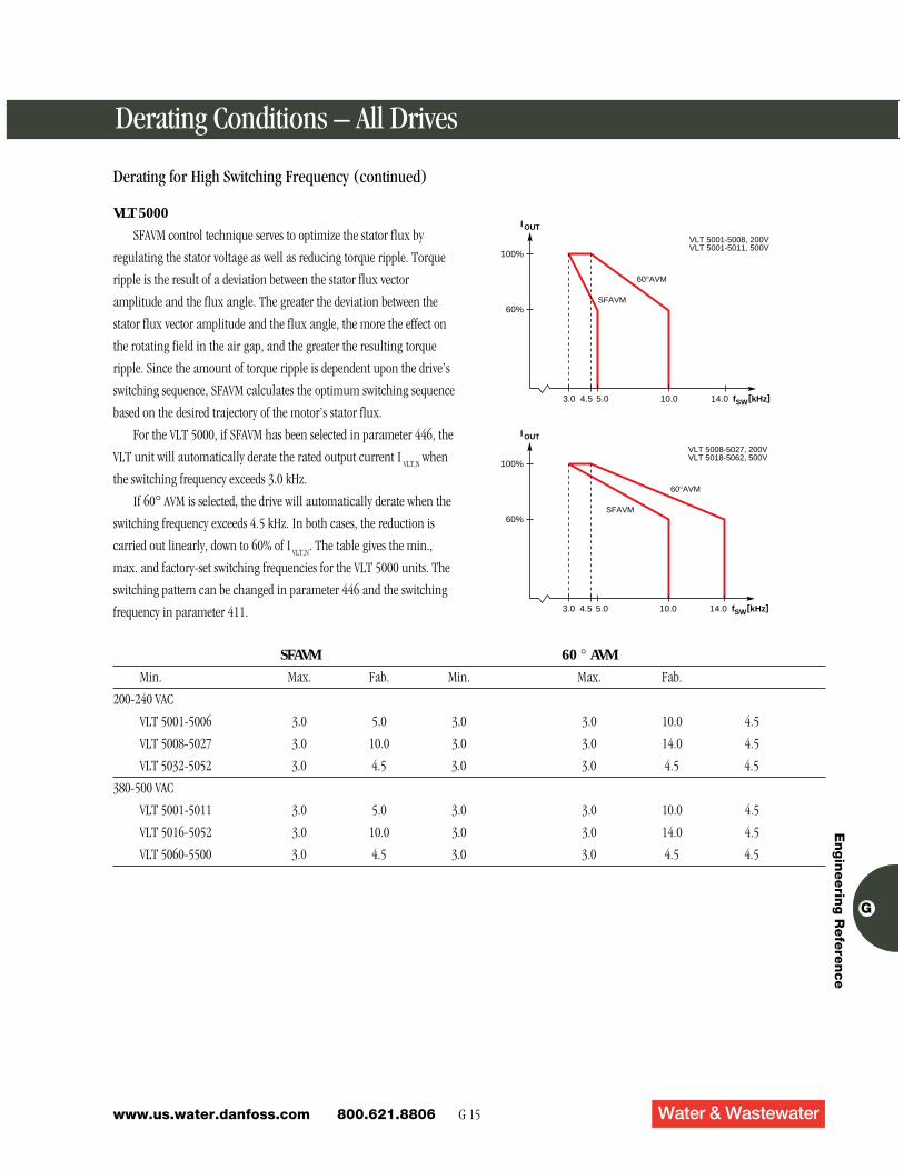
VLT 5000
SFAVM control technique serves to optimize the stator flux by
regulating the stator voltage as well as reducing torque ripple. Torque
ripple is the result of a deviation between the stator flux vector
amplitude and the flux angle. The greater the deviation between the
stator flux vector amplitude and the flux angle, the more the effect on
the rotating field in the air gap, and the greater the resulting torque
ripple. Since the amount of torque ripple is dependent upon the drive’s
switching sequence, SFAVM calculates the optimum switching sequence
based on the desired trajectory of the motor’s stator flux.
For the VLT 5000, if SFAVM has been selected in parameter 446, the
VLT unit will automatically derate the rated output current I VLT,N
when
the switching frequency exceeds 3.0 kHz.
If 60° AVM is selected, the drive will automatically derate when the
switching frequency exceeds 4.5 kHz. In both cases, the reduction is
carried out linearly, down to 60% of IVLT,N
. The table gives the min.,
max. and factory-set switching frequencies for the VLT 5000 units. The
switching pattern can be changed in parameter 446 and the switching
frequency in parameter 411.
SFAVM 60 ° AVM
Min. Max. Fab. Min. Max. Fab.
200-240 VAC
VLT 5001-5006 3.0 5.0 3.0 3.0 10.0 4.5
VLT 5008-5027 3.0 10.0 3.0 3.0 14.0 4.5
VLT 5032-5052 3.0 4.5 3.0 3.0 4.5 4.5
380-500 VAC
VLT 5001-5011 3.0 5.0 3.0 3.0 10.0 4.5
VLT 5016-5052 3.0 10.0 3.0 3.0 14.0 4.5
VLT 5060-5500 3.0 4.5 3.0 3.0 4.5 4.5
100%
60%
3.0 10.0 14.0 fSW[kHz]
SFAVM
I OUT
4.5 5.0
60°AVM
VLT 5001-5008, 200VVLT 5001-5011, 500V
100%
60%
3.0 10.0 14.0 fSW[kHz]
SFAVM
I OUT
4.5 5.0
60°AVM
VLT 5008-5027, 200VVLT 5018-5062, 500V
Derating for High Switching Frequency (continued)
G 16www.us.water.danfoss.com 800.621.8806
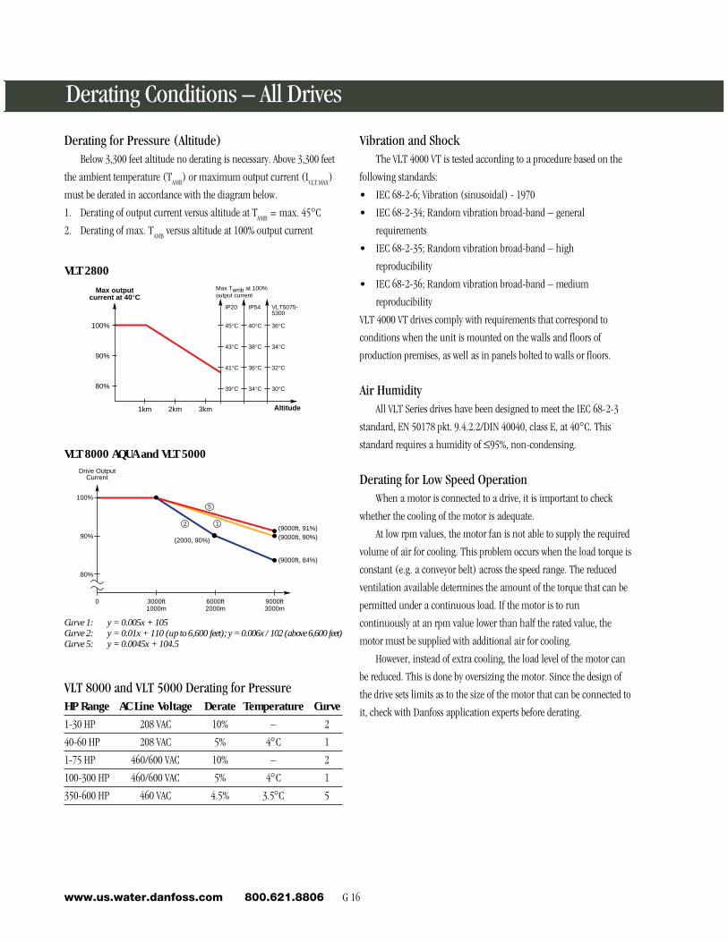
Derating for Pressure (Altitude)Below 3,300 feet altitude no derating is necessary. Above 3,300 feet
the ambient temperature (TAMB
) or maximum output current (IVLT.MAX
)
must be derated in accordance with the diagram below.
1. Derating of output current versus altitude at TAMB
= max. 45°C
2. Derating of max. TAMB
versus altitude at 100% output current
100%
90%
80%
1km 2km 3km
39°C
41°C
43°C
45°C
IP20
34°C
36°C
38°C
40°C
IP54
30°C
32°C
34°C
36°C
VLT5075-5300
Max outputcurrent at 40°C
Altitude
Max Tamb at 100%output current
VLT 2800
(9000ft, 91%)(9000ft, 90%)
(9000ft, 84%)
(2000, 90%)
9000ft3000m
6000ft2000m
3000ft1000m
0
100%
90%
80%
Drive OutputCurrent
12
5
VLT 8000 AQUA and VLT 5000
VLT 8000 and VLT 5000 Derating for PressureHP Range AC Line Voltage Derate Temperature Curve
1-30 HP 208 VAC 10% – 2
40-60 HP 208 VAC 5% 4°C 1
1-75 HP 460/600 VAC 10% – 2
100-300 HP 460/600 VAC 5% 4°C 1
350-600 HP 460 VAC 4.5% 3.5°C 5
Curve 1: y = 0.005x + 105Curve 2: y = 0.01x + 110 (up to 6,600 feet); y = 0.006x / 102 (above 6,600 feet)Curve 5: y = 0.0045x + 104.5
Vibration and ShockThe VLT 4000 VT is tested according to a procedure based on the
following standards:
• IEC 68-2-6; Vibration (sinusoidal) - 1970
• IEC 68-2-34; Random vibration broad-band – general
requirements
• IEC 68-2-35; Random vibration broad-band – high
reproducibility
• IEC 68-2-36; Random vibration broad-band – medium
reproducibility
VLT 4000 VT drives comply with requirements that correspond to
conditions when the unit is mounted on the walls and floors of
production premises, as well as in panels bolted to walls or floors.
Air HumidityAll VLT Series drives have been designed to meet the IEC 68-2-3
standard, EN 50178 pkt. 9.4.2.2/DIN 40040, class E, at 40°C. This
standard requires a humidity of ≤95%, non-condensing.
Derating for Low Speed OperationWhen a motor is connected to a drive, it is important to check
whether the cooling of the motor is adequate.
At low rpm values, the motor fan is not able to supply the required
volume of air for cooling. This problem occurs when the load torque is
constant (e.g. a conveyor belt) across the speed range. The reduced
ventilation available determines the amount of the torque that can be
permitted under a continuous load. If the motor is to run
continuously at an rpm value lower than half the rated value, the
motor must be supplied with additional air for cooling.
However, instead of extra cooling, the load level of the motor can
be reduced. This is done by oversizing the motor. Since the design of
the drive sets limits as to the size of the motor that can be connected to
it, check with Danfoss application experts before derating.
Derating Conditions – All Drives
G 17 Water & Wastewaterwww.us.water.danfoss.com 800.621.8806
En
gin
eerin
g R
efe
ren
ce
G
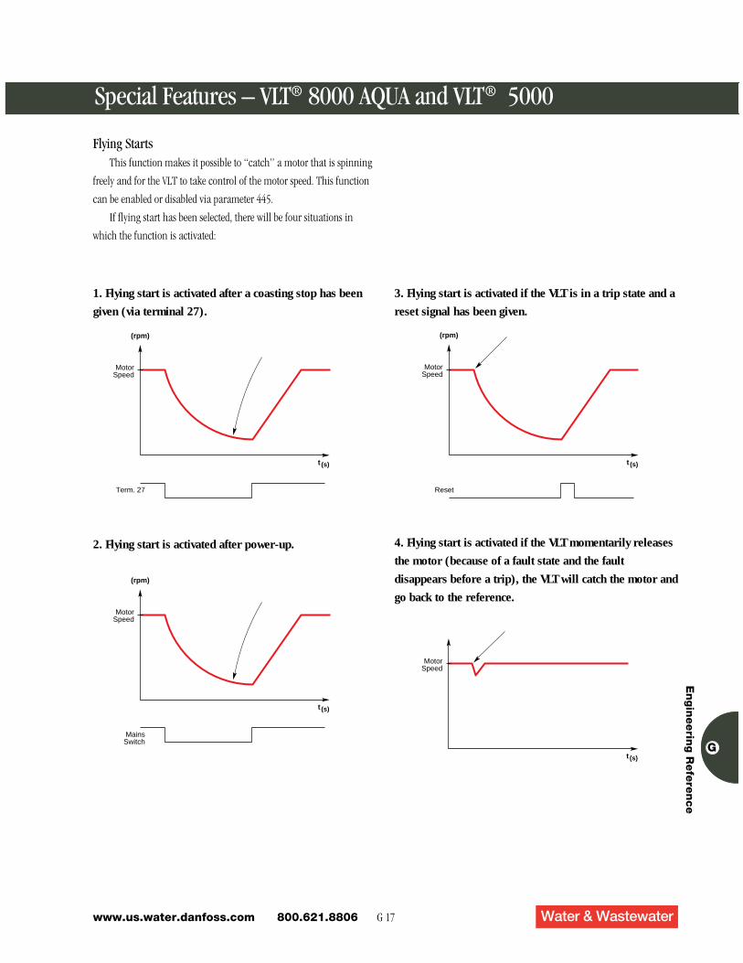
Flying StartsThis function makes it possible to “catch” a motor that is spinning
freely and for the VLT to take control of the motor speed. This function
can be enabled or disabled via parameter 445.
If flying start has been selected, there will be four situations in
which the function is activated:
Special Features – VLT® 8000 AQUA and VLT® 5000
t (s)
(rpm)
MotorSpeed
Term. 27
1. Flying start is activated after a coasting stop has been
given (via terminal 27).
t (s)
(rpm)
MotorSpeed
MainsSwitch
2. Flying start is activated after power-up.
3. Flying start is activated if the VLT is in a trip state and a
reset signal has been given.
t (s)
(rpm)
Reset
MotorSpeed
4. Flying start is activated if the VLT momentarily releases
the motor (because of a fault state and the fault
disappears before a trip), the VLT will catch the motor and
go back to the reference.
t (s)
MotorSpeed
G 18www.us.water.danfoss.com 800.621.8806
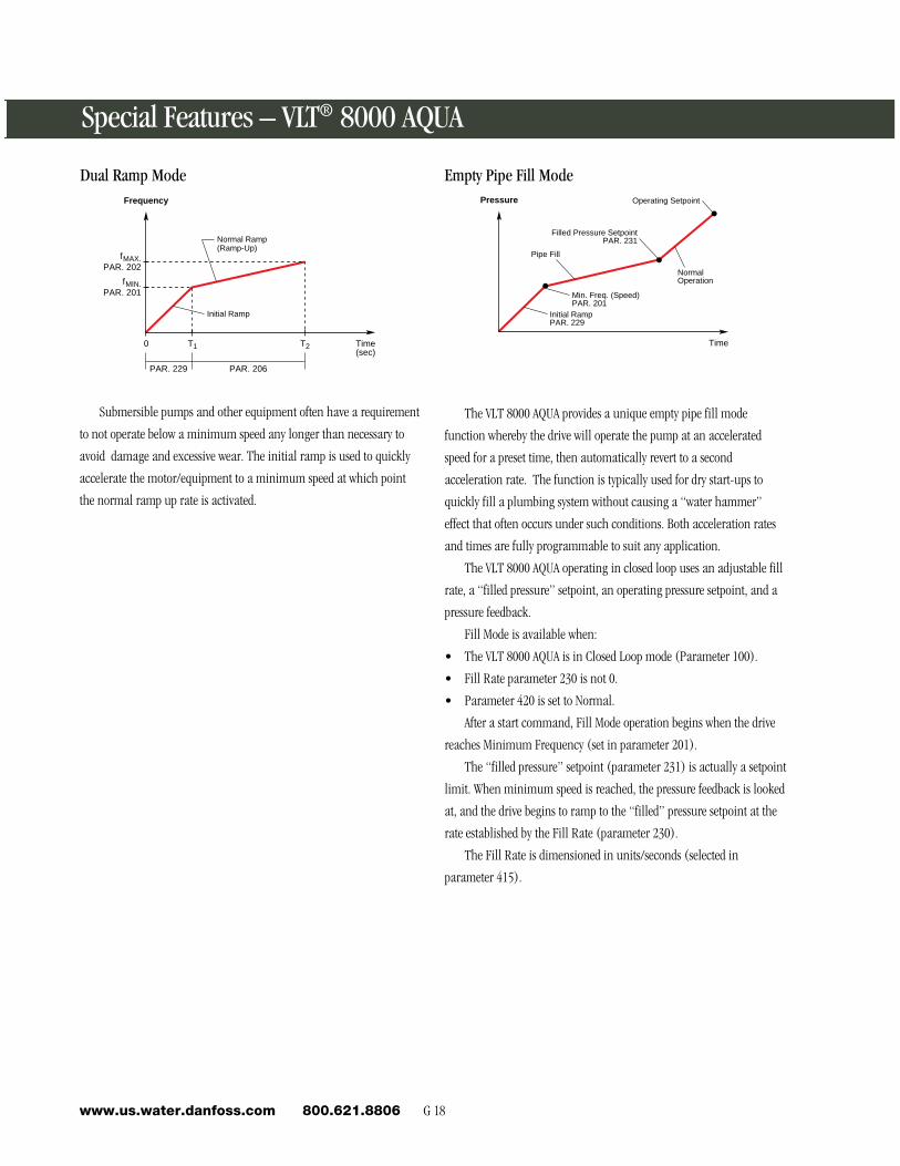
Dual Ramp Mode
Special Features – VLT® 8000 AQUA
Frequency
Time(sec)
0 T1 T2
fMIN.PAR. 201
PAR. 229 PAR. 206
fMAX.PAR. 202
Initial Ramp
Normal Ramp(Ramp-Up)
The VLT 8000 AQUA provides a unique empty pipe fill mode
function whereby the drive will operate the pump at an accelerated
speed for a preset time, then automatically revert to a second
acceleration rate. The function is typically used for dry start-ups to
quickly fill a plumbing system without causing a “water hammer”
effect that often occurs under such conditions. Both acceleration rates
and times are fully programmable to suit any application.
The VLT 8000 AQUA operating in closed loop uses an adjustable fill
rate, a “filled pressure” setpoint, an operating pressure setpoint, and a
pressure feedback.
Fill Mode is available when:
• The VLT 8000 AQUA is in Closed Loop mode (Parameter 100).
• Fill Rate parameter 230 is not 0.
• Parameter 420 is set to Normal.
After a start command, Fill Mode operation begins when the drive
reaches Minimum Frequency (set in parameter 201).
The “filled pressure” setpoint (parameter 231) is actually a setpoint
limit. When minimum speed is reached, the pressure feedback is looked
at, and the drive begins to ramp to the “filled” pressure setpoint at the
rate established by the Fill Rate (parameter 230).
The Fill Rate is dimensioned in units/seconds (selected in
parameter 415).
Submersible pumps and other equipment often have a requirement
to not operate below a minimum speed any longer than necessary to
avoid damage and excessive wear. The initial ramp is used to quickly
accelerate the motor/equipment to a minimum speed at which point
the normal ramp up rate is activated.
Empty Pipe Fill ModePressure
Time
Initial RampPAR. 229
Min. Freq. (Speed)PAR. 201
NormalOperation
Pipe Fill
Filled Pressure SetpointPAR. 231
Operating Setpoint
G 19 Water & Wastewaterwww.us.water.danfoss.com 800.621.8806
En
gin
eerin
g R
efe
ren
ce
G
Dual Control PIDThe integral PID regulator in VLT 8000 AQUA units is optimized
for use in water applications. This means that a number of specialized
functions are available in a the VLT 8000 AQUA, such as inverse
regulation, anti windup and a low pass noise filter. With the VLT 8000
AQUA, there is no need for extra modules to be installed. In addition,
the VLT 8000 AQUA is capable of recognizing two feedback signals.
For optimum process control, the VLT 8000 AQUA has the
capability to perform these functions to enhance the existing PID
regulation.
Inverse RegulationIn a normal regulation, the motor speed increases when the
reference/setpoint is higher than the feedback signal. For inverse
regulation, the speed is reduced when the feedback signal is lower than
the reference/setpoint.
Anti WindupThis function ensures that when either a frequency limit, current
limit or voltage limit is reached, the integrator will be initialized for a
frequency that corresponds to the present output frequency. This avoids
integration on a deviation between the reference/setpoint and the
actual state of the process.
Start-up ConditionsIn some applications, optimum setting of the process regulator
will require more time for the process state to be reached. In such
applications it might be advantageous for the VLT 8000 AQUA to bring
the motor to a fixed output frequency before the PID regulator is
activated.
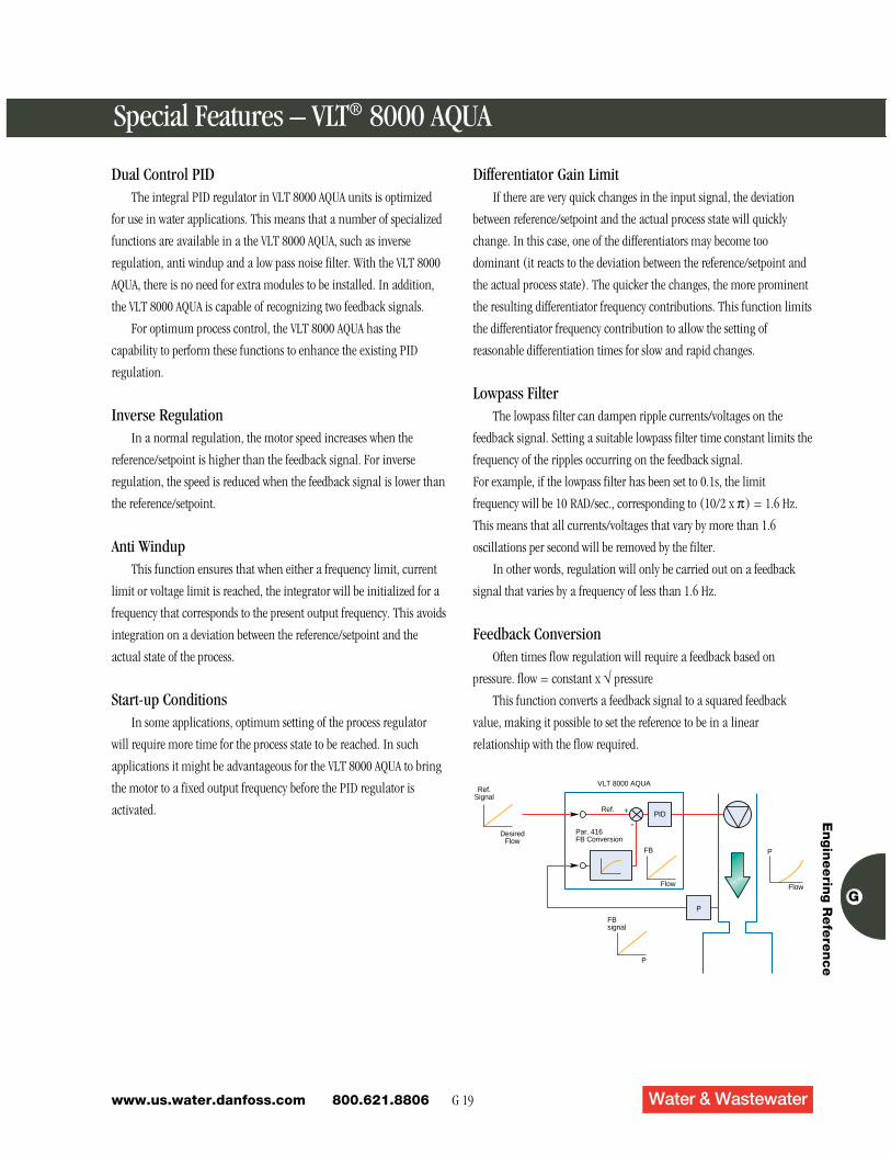
VLT 8000 AQUARef.
Signal
DesiredFlow
Ref. +
-Par. 416FB Conversion
FB
Flow
P
FBsignal
P
P
Flow
PID
Special Features – VLT® 8000 AQUA
Differentiator Gain LimitIf there are very quick changes in the input signal, the deviation
between reference/setpoint and the actual process state will quickly
change. In this case, one of the differentiators may become too
dominant (it reacts to the deviation between the reference/setpoint and
the actual process state). The quicker the changes, the more prominent
the resulting differentiator frequency contributions. This function limits
the differentiator frequency contribution to allow the setting of
reasonable differentiation times for slow and rapid changes.
Lowpass FilterThe lowpass filter can dampen ripple currents/voltages on the
feedback signal. Setting a suitable lowpass filter time constant limits the
frequency of the ripples occurring on the feedback signal.
For example, if the lowpass filter has been set to 0.1s, the limit
frequency will be 10 RAD/sec., corresponding to (10/2 x π) = 1.6 Hz.
This means that all currents/voltages that vary by more than 1.6
oscillations per second will be removed by the filter.
In other words, regulation will only be carried out on a feedback
signal that varies by a frequency of less than 1.6 Hz.
Feedback ConversionOften times flow regulation will require a feedback based on
pressure. flow = constant x √ pressure
This function converts a feedback signal to a squared feedback
value, making it possible to set the reference to be in a linear
relationship with the flow required.
G 20www.us.water.danfoss.com 800.621.8806
Special Features – VLT® 8000 AQUA
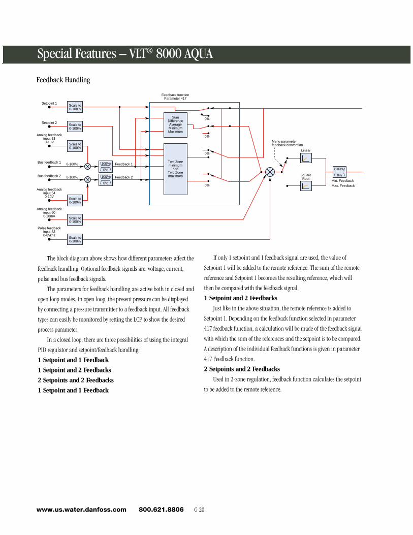
The block diagram above shows how different parameters affect the
feedback handling. Optional feedback signals are: voltage, current,
pulse and bus feedback signals.
The parameters for feedback handling are active both in closed and
open loop modes. In open loop, the present pressure can be displayed
by connecting a pressure transmitter to a feedback input. All feedback
types can easily be monitored by setting the LCP to show the desired
process parameter.
In a closed loop, there are three possibilities of using the integral
PID regulator and setpoint/feedback handling:
1 Setpoint and 1 Feedback
1 Setpoint and 2 Feedbacks
2 Setpoints and 2 Feedbacks
1 Setpoint and 1 Feedback
If only 1 setpoint and 1 feedback signal are used, the value of
Setpoint 1 will be added to the remote reference. The sum of the remote
reference and Setpoint 1 becomes the resulting reference, which will
then be compared with the feedback signal.
1 Setpoint and 2 Feedbacks
Just like in the above situation, the remote reference is added to
Setpoint 1. Depending on the feedback function selected in parameter
417 feedback function, a calculation will be made of the feedback signal
with which the sum of the references and the setpoint is to be compared.
A description of the individual feedback functions is given in parameter
417 Feedback function.
2 Setpoints and 2 Feedbacks
Used in 2-zone regulation, feedback function calculates the setpoint
to be added to the remote reference.
Linear
SquareRoot Min. Feedback
Max. Feedback
Menu parameterfeedback conversion
0%
0%
0%
0%
Feedback functionParameter 417
Setpoint 1
Setpoint 2
Analog feedbackinput 530-10V
Bus feedback 1
Bus feedback 2
Analog feedbackinput 540-10V
Analog feedbackinput 600-20mA
Pulse feedbackinput 330-65khz
Feedback 1
Feedback 2
0-100%
0-100%
100%
0%
Two Zoneminimum
andTwo Zonemaximum
SumDifferenceAverageMinimumMaximum
100%
0%
100%
0%
Scale to0-100%
Scale to0-100%
Scale to0-100%
Scale to0-100%
Scale to0-100%
Scale to0-100%
Feedback Handling
G 21 Water & Wastewaterwww.us.water.danfoss.com 800.621.8806
En
gin
eerin
g R
efe
ren
ce
G
AEO (Automatic Energy Optimizer)• Minimizes energy consumption
• Maximizes motor efficiency by controlling the motor
magnetization current
• Reduces motor noise
• Simplifies commissioning
• Improved load shock handling
• Improved handling of fast reference changes
The VLT 8000 AQUA uses a unique control scheme, called AEO
(Automatic Energy Optimization ), to ensure that the relationship
between voltage and frequency is always optimum for the motor’s load.
By doing this, an additional 5% energy savings can be realized in a
typical pumping application.
In order to automatically provide the correct voltage at any
operating frequency and load, the drive must continuously monitor the
motor’s status and respond to any changes. The VLT 8000 AQUA’s
unique VVCPLUS control algorithm is central to this. Current is monitored
on all three motor phases so that both the real and the reactive
components of motor current are known at all times. In addition, the
Automatic Motor Adaptation (AMA) function, which accurately
determines critical motor parameters, allows the drive to interpret the
current readings to determine the amount of magnetizing current
required by the load.
The result is that the drive automatically maintains peak motor
efficiency under all conditions. During acceleration, the output voltages
will tend to be high since additional torque is needed to overcome the
inertia of the load. After the motor reaches the desired speed, the VLT
8000 AQUA automatically detects the stead-state load level and reduces
the output voltage to maximize motor efficiency. If the load changes,
as could occur if a valve in a pumping system suddenly opens, the drive
detects the load change and immediately increases the output voltage
to maintain control of the motor.
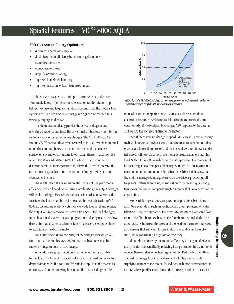
The figure above shows the range of the voltages over which AEO
functions. As the graph shows, AEO allows the drive to reduce the
motor’s voltage in order to save energy.
Automatic energy optimization’s major benefit is for variable
torque loads. As the motor’s speed is decreased, the load on the motor
drops dramatically. If a constant V/f ratio is supplied to the motor, its
efficiency will suffer. Knowing how much the motor voltage can be
0
Mo
tor
Vo
ltag
e %
25
Frequency %10 20 30 40 50 60 70 80 90 100
50
75
100
Voltage rangein whichAEO-functionwill typicallybe active
AEO allows the VLT 8000 AQUA to control voltage over a wide range in order tomatch the drive’s output with the load’s requirements.
reduced before motor performance begins to suffer is difficult to
determine manually. AEO handles this decision automatically and
continuously. If the load profile changes, AEO responds to the change
and adjusts the voltage supplied to the motor.
Even if there were no change in speed, AEO can still produce energy
savings. In order to provide a safety margin, most motors for pumping
systems are larger than needed to drive the load. As a result, even under
full speed, full flow conditions, the motor is operating at less than full
load. Without the voltage reduction that AEO provides, the motor would
be operating at less than peak efficiency. With the VLT 8000 AQUA it is
common to notice an output voltage from the drive which is less than
the motor’s nameplate rating, even when the drive is producing full
frequency. Rather than being an indication that something is wrong,
this shows that AEO is compensating for a motor that is oversized for the
application.
Even variable speed, constant pressure applications benefit from
AEO. One example of such an application is a pump system for water
filtration. Here, the purpose of the drive is to maintain a constant flow,
even as the filter becomes dirty. As the filter becomes loaded, the drive
automatically increases the speed and the load on the motor increases.
AEO ensures that sufficient torque is always available on the motor’s
shaft, while maintaining high motor efficiency.
Although maximizing the motor’s efficiency is the goal of AEO, it
also provides side benefits. By reducing heat generation in the motor, it
reduces thermal stresses, extending motor life. Reduced current flows
also reduce energy losses in the drive and all other components
supplying current to the motor. In addition, reducing motor current to
the lowest level possible minimizes audible noise generation in the motor.
Special Features – VLT® 8000 AQUA
G 22www.us.water.danfoss.com 800.621.8806
• Simplifies start-up
• Automatically extends the acceleration time to prevent tripping on
overcurrent
• Automatically extends the deceleration time to prevent tripping on
overvoltage
The Autoramping function prevents the drive from tripping when
the acceleration or deceleration ramp time values are inadequate. If the
ramp up time is too fast, it maximizes the acceleration rate without
exceeding the drives current limit by extending the acceleration time.
For instance, a decelerating motor will often send energy back to the
drive, causing an overvoltage condition in the DC bus. Under these
circumstances, autoramping will extend the ramp down time to keep
the drive from tripping.
Speed
Time
Special Features – VLT® 8000 AQUA
Autoramping
Par. 405Wake up frequency
20 hz
OutputFrequency
Theoretical outputfrequency
Par. 404Sleep frequency
10 hzPar. 201
Min. frequency5 hz
Time [%]
fout
Par. 403 10 sec.
Sleep mode timer
Sleep Wake up
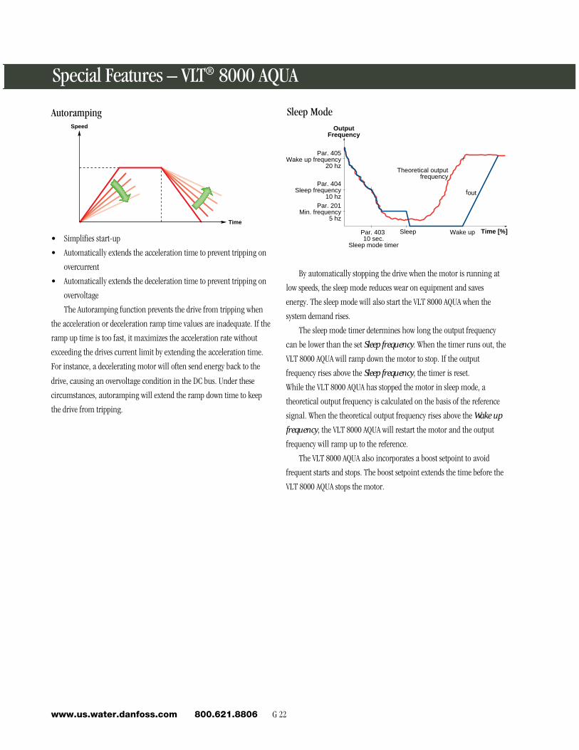
By automatically stopping the drive when the motor is running at
low speeds, the sleep mode reduces wear on equipment and saves
energy. The sleep mode will also start the VLT 8000 AQUA when the
system demand rises.
The sleep mode timer determines how long the output frequency
can be lower than the set Sleep frequency. When the timer runs out, the
VLT 8000 AQUA will ramp down the motor to stop. If the output
frequency rises above the Sleep frequency, the timer is reset.
While the VLT 8000 AQUA has stopped the motor in sleep mode, a
theoretical output frequency is calculated on the basis of the reference
signal. When the theoretical output frequency rises above the Wake up
frequency, the VLT 8000 AQUA will restart the motor and the output
frequency will ramp up to the reference.
The VLT 8000 AQUA also incorporates a boost setpoint to avoid
frequent starts and stops. The boost setpoint extends the time before the
VLT 8000 AQUA stops the motor.
Sleep Mode
G 23 Water & Wastewaterwww.us.water.danfoss.com 800.621.8806
En
gin
eerin
g R
efe
ren
ce
G
AQUA
VLT
VLT® 8000 AQUA – PID Control
Example of Constant Pressure Regulation in WaterSupply System
The demand for water from waterworks varies considerably during
the course of a 24-hour period. During the night, practically no water is
used, while in the morning and evening, the consumption is high. In
order to maintain a suitable pressure in the water supply lines in
relation to the current demand, the water supply pumps are equipped
with speed control. The use of drives enables the energy consumed by
the pumps to be kept at a minimum, while optimizing the water supply
to consumers.
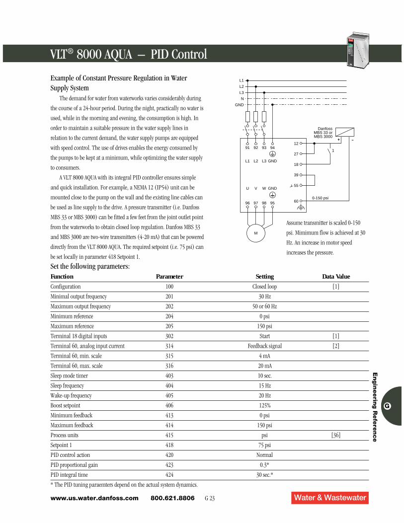
A VLT 8000 AQUA with its integral PID controller ensures simple
and quick installation. For example, a NEMA 12 (IP54) unit can be
mounted close to the pump on the wall and the existing line cables can
be used as line supply to the drive. A pressure transmitter (i.e. Danfoss
MBS 33 or MBS 3000) can be fitted a few feet from the joint outlet point
from the waterworks to obtain closed loop regulation. Danfoss MBS 33
and MBS 3000 are two-wire transmitters (4-20 mA) that can be powered
directly from the VLT 8000 AQUA. The required setpoint (i.e. 75 psi) can
be set locally in parameter 418 Setpoint 1.
Set the following parameters:Function Parameter Setting Data Value
Configuration 100 Closed loop [1]
Minimal output frequency 201 30 Hz
Maximum output frequency 202 50 or 60 Hz
Minimum reference 204 0 psi
Maximum reference 205 150 psi
Terminal 18 digital inputs 302 Start [1]
Terminal 60, analog input current 314 Feedback signal [2]
Terminal 60, min. scale 315 4 mA
Terminal 60, max. scale 316 20 mA
Sleep mode timer 403 10 sec.
Sleep frequency 404 15 Hz
Wake-up frequency 405 20 Hz
Boost setpoint 406 125%
Minimum feedback 413 0 psi
Maximum feedback 414 150 psi
Process units 415 psi [36]
Setpoint 1 418 75 psi
PID control action 420 Normal
PID proportional gain 423 0.3*
PID integral time 424 30 sec.*
* The PID tuning paraemters depend on the actual system dynamics.
L1
L2
L3
N
GND
1
+ -
600-150 psi
DanfossMBS 33 orMBS 3000
55
39
18
27
12
M
95989796
94939291
GNDL3L2L1
GNDWVU
Assume transmitter is scaled 0-150
psi. Mimimum flow is achieved at 30
Hz. An increase in motor speed
increases the pressure.

G 24www.us.water.danfoss.com 800.621.8806
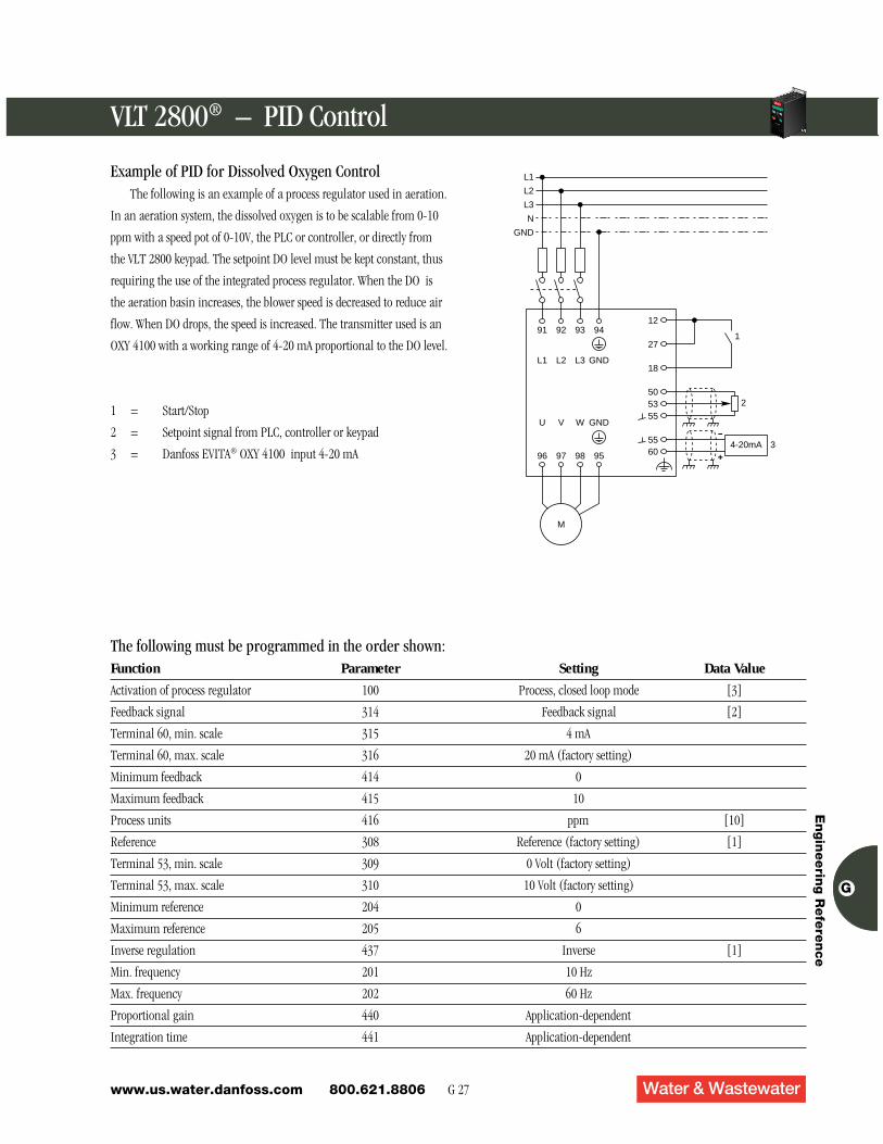
Example of PID for Dissolved Oxygen ControlThe following is an example of a process regulator used in aeration.
In an aeration system, the dissolved oxygen is to be scalable from 0-10
ppm with a speed pot of 0-10V, the PLC or controller, or directly from
the VLT 8000 AQUA keypad. The setpoint DO level must be kept
constant, thus requiring the use of the integrated process regulator.
When the DO is the aeration basin increases, the blower speed is
decreased to reduce air flow. When DO drops, the speed is increased. The
transmitter used is an OXY 4100 with a working range of 4-20 mA
proportional to the DO level.
1 = Start/Stop
2 = Setpoint signal from PLC, controller or keypad
3 = Danfoss EVITA® OXY 4100 input 4-20 mA
The following must be programmed in the order shown:Function Parameter Setting Data Value
Activation of process regulator 100 Process, closed loop mode [3]
Feedback signal 314 Feedback signal [2]
Terminal 60, min. scale 315 4 mA
Terminal 60, max. scale 316 20 mA (factory setting)
Minimum feedback 414 0
Maximum feedback 415 10
Process units 416 ppm [10]
Reference 308 Reference (factory setting) [1]
Terminal 53, min. scale 309 0 Volt (factory setting)
Terminal 53, max. scale 310 10 Volt (factory setting)
Minimum reference 204 0
Maximum reference 205 6
PID control action 420 Normal
Min. frequency 201 30
Max. frequency 202 60
Proportional gain 440 423
Integration time 441 424
L1
L2
L3
N
GND
1
2
4-20mA 3+
-
6055
555350
18
27
12
M
95989796
94939291
GNDL3L2L1
GNDWVU
VLT® 8000 AQUA – PID Control AQUA
VLT
G 25 Water & Wastewaterwww.us.water.danfoss.com 800.621.8806
En
gin
eerin
g R
efe
ren
ce
G
AQUA
VLT
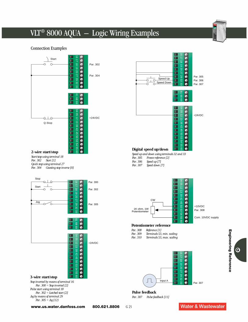
Connection Examples
VLT® 8000 AQUA – Logic Wiring Examples
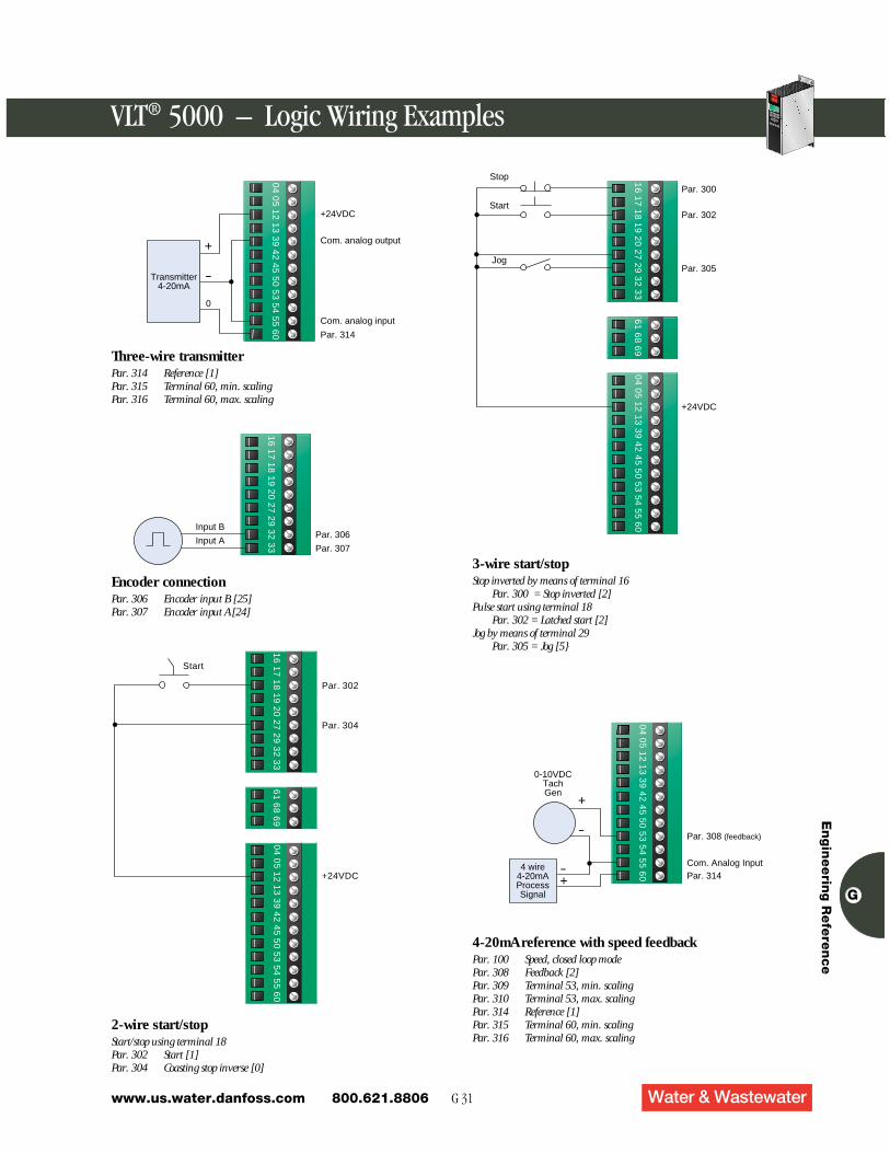
2-wire start/stopStart/stop using terminal 18Par. 302 Start [1]Quick stop using terminal 27Par. 304 Coasting stop inverse [0]
Par. 302
Par. 304
+24VDC
Q-Stop
16
17
18
19
20
27
29
32
33
61
68
69
04
05
12
13
39
42
45
50
53
54
55
60
Start
Par. 300
Par. 302
Par. 305
+24VDC
16
17
18
19
20
27
29
32
33
61
68
69
04
05
12
13
39
42
45
50
53
54
55
60
Stop
Start
Jog
3-wire start/stopStop inverted by means of terminal 16
Par. 300 = Stop inverted [2]Pulse start using terminal 18
Par. 302 = Latched start [2]Jog by means of terminal 29
Par. 305 = Jog [12}
Par. 305
Par. 306
Par. 307
+24VDC
16
17
18
19
20
27
29
32
33
61
68
69
04
05
12
13
39
42
45
50
53
54
55
60
Speed Up
Speed Down
Digital speed up/downSpeed up and down using terminals 32 and 33Par. 305 Freeze reference [2]Par. 306 Speed up [7]Par. 307 Speed down [7]
+10VDC
Par. 308
Com. 10VDC supply
04 05 12 13 39 42 45 50 53 54 55 60
1K ohm, 1WPotentiometer
CW
Potentiometer referencePar. 308 Reference [1]Par. 309 Terminals 53, min. scalingPar. 310 Terminals 53, max. scaling
Par. 307
16
17
18
19
20
27
29
32
33Input A
Pulse feedbackPar. 307 Pulse feedback [11]

G 26www.us.water.danfoss.com 800.621.8806
VLT® 8000 AQUA – Logic Wiring Examples AQUA
VLT
Connection Examples
Two-wire transmitter
+24VDC
Com. 24VDC supply
Com. analog input
Par. 314
04
05
12
13
39
42
45
50
53
54
55
60
Transmitter4-20mA
+
-
Transmitter connectionPar. 314 Reference [1]Par. 315 Terminal 60, min. scalingPar. 316 Terminal 60, max. scaling
Com. analog input
Par. 314
04
05
12
13
39
42
45
50
53
54
55
60
4-20mA
Transmitterw/External
supply
VACSupply
Par. 306Par. 307
+24VDC
16
17
18
19
20
27
29
32
33
61
68
69
04
05
12
13
39
42
45
50
53
54
55
60
LSB
MSB
Setup changeSelection of setup using terminals 32 and 33.Par. 306 Selection of setup, LSB [4]Par. 307 Selection of setup, MSB [4]Par. 002 Multi-setup [5]
Speed Input 33 Input 321 0 02 0 X3 X 04 X X
O = Open X = Closed
Par. 306Par. 307
+24VDC
16
17
18
19
20
27
29
32
33
61
68
69
04
05
12
13
39
42
45
50
53
54
55
60
LSB
MSB
RunStop
Four preset speed referencesPar. 305 Preset reference on [6]Par. 211 Speed #1Par. 212 Speed #2Par. 213 Speed #3Par. 214 Speed #4Par. 302 Start [1]Par. 306 Preset Reference LSB [6]Par. 307 Preset Reference MSB [6]
Speed Input 33 Input 321 0 02 0 X3 X 04 X X
O = Open X = ClosedPar. 302 Start [1]Par. 304 Coast Inverse [0]
G 27 Water & Wastewaterwww.us.water.danfoss.com 800.621.8806
En
gin
eerin
g R
efe
ren
ce
G
Example of PID for Dissolved Oxygen ControlThe following is an example of a process regulator used in aeration.
In an aeration system, the dissolved oxygen is to be scalable from 0-10
ppm with a speed pot of 0-10V, the PLC or controller, or directly from
the VLT 2800 keypad. The setpoint DO level must be kept constant, thus
requiring the use of the integrated process regulator. When the DO is
the aeration basin increases, the blower speed is decreased to reduce air
flow. When DO drops, the speed is increased. The transmitter used is an
OXY 4100 with a working range of 4-20 mA proportional to the DO level.
1 = Start/Stop
2 = Setpoint signal from PLC, controller or keypad
3 = Danfoss EVITA® OXY 4100 input 4-20 mA
The following must be programmed in the order shown:Function Parameter Setting Data Value
Activation of process regulator 100 Process, closed loop mode [3]
Feedback signal 314 Feedback signal [2]
Terminal 60, min. scale 315 4 mA
Terminal 60, max. scale 316 20 mA (factory setting)
Minimum feedback 414 0
Maximum feedback 415 10
Process units 416 ppm [10]
Reference 308 Reference (factory setting) [1]
Terminal 53, min. scale 309 0 Volt (factory setting)
Terminal 53, max. scale 310 10 Volt (factory setting)
Minimum reference 204 0
Maximum reference 205 6
Inverse regulation 437 Inverse [1]
Min. frequency 201 10 Hz
Max. frequency 202 60 Hz
Proportional gain 440 Application-dependent
Integration time 441 Application-dependent
L1
L2
L3
N
GND
1
2
4-20mA 3+
-
6055
555350
18
27
12
M
95989796
94939291
GNDL3L2L1
GNDWVU
VLT 2800® – PID Control -+
CHANGEDATA
QUICKMENU
START
STOPRESET
ALARMWARNING
ON
G 28www.us.water.danfoss.com 800.621.8806
VLT® 2800 – PID Control -+
CHANGEDATA
QUICKMENU
START
STOPRESET
ALARMWARNING
ON
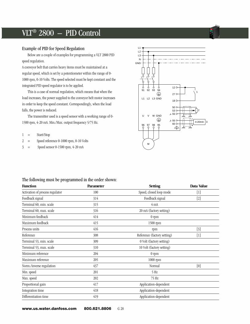
Example of PID for Speed RegulationBelow are a couple of examples for programming a VLT 2800 PID
speed regulation.
A conveyor belt that carries heavy items must be maintained at a
regular speed, which is set by a potentiometer within the range of 0-
1000 rpm, 0-10 Volts. The speed selected must be kept constant and the
integrated PID speed regulator is to be applied.
This is a case of normal regulation, which means that when the
load increases, the power supplied to the conveyor belt motor increases
in order to keep the speed constant. Correspondingly, when the load
falls, the power is reduced.
The transmitter used is a speed sensor with a working range of 0-
1500 rpm, 4-20 mA. Min./Max. output frequency 5/75 Hz.
1 = Start/Stop
2 = Speed reference 0-1000 rpm, 0-10 Volts
3 = Speed sensor 0-1500 rpm, 4-20 mA
The following must be programmed in the order shown:Function Parameter Setting Data Value
Activation of process regulator 100 Speed, closed loop mode [1]
Feedback signal 314 Feedback signal [2]
Terminal 60, min. scale 315 4 mA
Terminal 60, max. scale 316 20 mA (factory setting)
Minimum feedback 414 0 rpm
Maximum feedback 415 1500 rpm
Process units 416 rpm [3]
Reference 308 Reference (factory setting) [1]
Terminal 53, min. scale 309 0 Volt (factory setting)
Terminal 53, max. scale 310 10 Volt (factory setting)
Minimum reference 204 0 rpm
Maximum reference 205 1000 rpm
Norm./inverse regulation 437 Normal [0]
Min. speed 201 5 Hz
Max. speed 202 75 Hz
Proportional gain 417 Application-dependent
Integration time 418 Application-dependent
Differentiation time 419 Application-dependent
L1
L2
L3
N
GND
1
2
4-20mA 3+
-
6055
555350
18
27
12
M
95989796
94939291
GNDL3L2L1
GNDWVU

G 29 Water & Wastewaterwww.us.water.danfoss.com 800.621.8806
En
gin
eerin
g R
efe
ren
ce
G
Connection Examples
1218
1920
2729
+24VDCPar. 302
Par. 304
+24VDCPar. 302
Par. 305
Par. 303
1218
1920
2729
+24VDC
Par. 303
Par. 305
Par. 307
1218
1920
2733
29
+10V OutPar. 308GND
4650
5355
1K ohm53
5360
Com. Analog InputPar. 314
1218
19
+24VDC
VacSupply
5560 Par. 314
Transmitter4-20mA
Transmitter4-20mA
ExternalSupply
Connection of a 2-wire transmitter as feedback
to terminal 60
Par. 314 Analog input = Feedback [2]
Par. 315 Terminal 60, min. scaling = 4 mA
Par. 316 Terminal 60, max. scaling = 20 mA
Voltage reference via a potentiometer
Par. 308 Analog input = Reference [1]
Par. 309 Terminal 53, min. scaling = 0 Volt.
Par. 310 Terminal 53, max. scaling - 10 Volt.
Speed up/down using terminals 29/33
Par. 303 Digital input = Freeze reference [14]
Par. 305 Digital input = Speed up [16]
Par. 307 Digital input = Speed down [17]
Pulse start using terminal 18 and pulse stop using
terminal 19. In addition, the jog frequency is activated via
terminal 29
Par. 302 Digital input = Pulse start [8]
Par. 303 Digital input = Stop inverse [6]
Par. 304 Digital input = Coasting stop inverse [2]
Par. 305 Digital input = Jog [13]
Two-wire start/stop using terminals 18 and coasting stop
using terminal 27
Par. 302 Digital input = Start [7]
Par. 304 Digital input = Coasting stop inverse [2]
VLT® 2800 – Logic Wiring Examples -+
CHANGEDATA
QUICKMENU
START
STOPRESET
ALARMWARNING
ON
G 30www.us.water.danfoss.com 800.621.8806
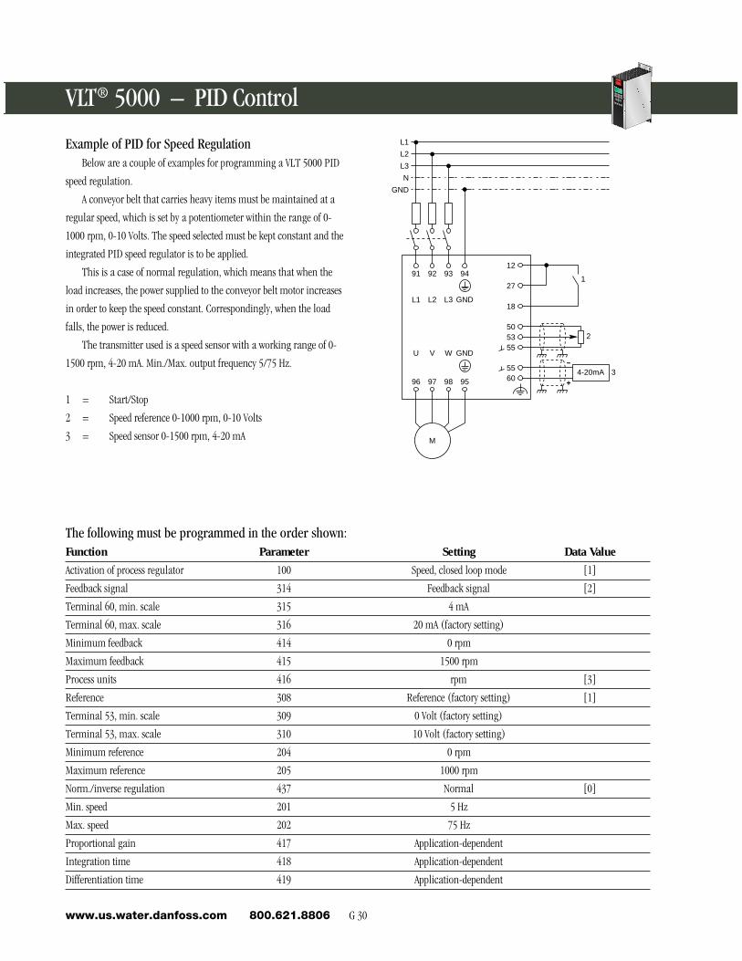
Example of PID for Speed RegulationBelow are a couple of examples for programming a VLT 5000 PID
speed regulation.
A conveyor belt that carries heavy items must be maintained at a
regular speed, which is set by a potentiometer within the range of 0-
1000 rpm, 0-10 Volts. The speed selected must be kept constant and the
integrated PID speed regulator is to be applied.
This is a case of normal regulation, which means that when the
load increases, the power supplied to the conveyor belt motor increases
in order to keep the speed constant. Correspondingly, when the load
falls, the power is reduced.
The transmitter used is a speed sensor with a working range of 0-
1500 rpm, 4-20 mA. Min./Max. output frequency 5/75 Hz.
1 = Start/Stop
2 = Speed reference 0-1000 rpm, 0-10 Volts
3 = Speed sensor 0-1500 rpm, 4-20 mA
The following must be programmed in the order shown:Function Parameter Setting Data Value
Activation of process regulator 100 Speed, closed loop mode [1]
Feedback signal 314 Feedback signal [2]
Terminal 60, min. scale 315 4 mA
Terminal 60, max. scale 316 20 mA (factory setting)
Minimum feedback 414 0 rpm
Maximum feedback 415 1500 rpm
Process units 416 rpm [3]
Reference 308 Reference (factory setting) [1]
Terminal 53, min. scale 309 0 Volt (factory setting)
Terminal 53, max. scale 310 10 Volt (factory setting)
Minimum reference 204 0 rpm
Maximum reference 205 1000 rpm
Norm./inverse regulation 437 Normal [0]
Min. speed 201 5 Hz
Max. speed 202 75 Hz
Proportional gain 417 Application-dependent
Integration time 418 Application-dependent
Differentiation time 419 Application-dependent
L1
L2
L3
N
GND
1
2
4-20mA 3+
-
6055
555350
18
27
12
M
95989796
94939291
GNDL3L2L1
GNDWVU
VLT® 5000 – PID Control
G 31 Water & Wastewaterwww.us.water.danfoss.com 800.621.8806
En
gin
eerin
g R
efe
ren
ce
G
Par. 302
Par. 304
+24VDC
16
17
18
19
20
27
29
32
33
61
68
69
04
05
12
13
39
42
45
50
53
54
55
60
Start
Par. 306
Par. 307
16
17
18
19
20
27
29
32
33
Input B
Input A
+24VDC
Com. analog output
Com. analog input
Par. 314
04
05
12
13
39
42
45
50
53
54
55
60
+
-
0
Transmitter4-20mA
Three-wire transmitterPar. 314 Reference [1]Par. 315 Terminal 60, min. scalingPar. 316 Terminal 60, max. scaling
2-wire start/stopStart/stop using terminal 18Par. 302 Start [1]Par. 304 Coasting stop inverse [0]
Encoder connectionPar. 306 Encoder input B [25]Par. 307 Encoder input A [24]
Par. 300
Par. 302
Par. 305
+24VDC
16
17
18
19
20
27
29
32
33
61
68
69
04
05
12
13
39
42
45
50
53
54
55
60
Stop
Start
Jog
3-wire start/stopStop inverted by means of terminal 16
Par. 300 = Stop inverted [2]Pulse start using terminal 18
Par. 302 = Latched start [2]Jog by means of terminal 29
Par. 305 = Jog [5}
Par. 308 (feedback)
Com. Analog InputPar. 314
04
05
12
13
39
42
45
50
53
54
55
60
0-10VDCTachGen
+
-
+-4 wire
4-20mAProcessSignal
4-20mA reference with speed feedbackPar. 100 Speed, closed loop modePar. 308 Feedback [2]Par. 309 Terminal 53, min. scalingPar. 310 Terminal 53, max. scalingPar. 314 Reference [1]Par. 315 Terminal 60, min. scalingPar. 316 Terminal 60, max. scaling
VLT® 5000 – Logic Wiring Examples

G 32www.us.water.danfoss.com 800.621.8806
Par. 306Par. 307
+24VDC
16
17
18
19
20
27
29
32
33
61
68
69
04
05
12
13
39
42
45
50
53
54
55
60
LSB
MSB
Par. 301
Par. 306
Par. 307
+24VDC
16
17
18
19
20
27
29
32
33
61
68
69
04
05
12
13
39
42
45
50
53
54
55
60
Speed Up
Speed Down
+10VDC
Par. 308
Com. 10VDC supply
04 05 12 13 39 42 45 50 53 54 55 60
1K ohm, 1WPotentiometer
CW
Two-wire transmitter
+24VDC
Com. 24VDC supply
Com. analog input
Par. 314
04
05
12
13
39
42
45
50
53
54
55
60
Transmitter4-20mA
+
-
Setup changeSelection of setup using terminals 32 and 33.Par. 306 Selection of setup,LSB [10]Par. 307 Selection of setup, MSB [10]Par. 004 Multi-setup [5]
Speed Input 33 Input 321 0 02 0 X3 X 04 X X
O = Open X = Closed
Potentiometer referencePar. 308 Reference [1]Par. 309 Terminals 53, min. scalingPar. 310 Terminals 53, max. scaling
Digital speed up/down
Speed up and down using terminals 32 and 33.Par. 306 Speed up [9]Par. 307 Speed down [9]Par. 301 Freeze reference
Digital InputDigital InputDigital InputDigital InputCommonDigital InputDigital Input
Digital Input
Digital Input
Earthground
Positive
Negative
Relay
+24VDC Supply
-24VDC Supply
Common
Digital/Analog Output
Digital/Analog Output
+10VDC SupplyAnalog InputAnalog Input
Common
Analog Input
300301302303
304305
306
307
RS 485
323-325
309-320
321-322
308-310311-313
314-316
Parameter
1617
1819
2027
2932
3361
6869
0405
1213
3942
4553
5455
5060
VLT® 5000 – Logic Wiring Examples
Connection Examples