Damage of plates due to impact, dynamic pressure and
14
10(2013) 767 – 780 This paper is a complete version of an extended abstract presented at the 11 th Asia-Pacific Conference on Engineering Plasticity (AEPA 2012), Singapore, December 2012. Abstract It is the purpose of this article to present design equations which can be used to predict the damage of ductile plating when subjected to mass impact, dynamic pressure or impulsive loadings. The external loadings are sufficiently severe to produce inelastic material behaviour and produce finite transverse displacement, or geometry change, ef- fects. The damage is characterised as the final or permanent transverse displacement of a plate. The theoretical method predicts values for the maximum perma- nent transverse displacements which agree reasonably well with the corresponding experimental results generated on aluminium alloy cir- cular, square and rectangular plates. Thus, the equations presented in this article are valuable for preliminary design purposes and for foren- sic studies, while the experimental data can be used for validating numerical schemes. Keywords rectangular plate, square plate, circular plate, inelastic deformations, design equations, aluminium alloy plates, mass impact, dynamic pres- sure pulse, impulsive loadings, finite-displacements. Damage of plates due to impact, dynamic pressure and explosive loads 1 INTRODUCTION Simple and reliable theoretical methods are still valuable for design purposes, particularly for pre- liminary design, hazard assessments, integrity and security studies and for forensic investigations after accidents. In these practical situations, a designer is interested in the damage that a structure sustains under external loadings which produce large deformations and associated inelastic strains. In the case of transversely loaded beams and plates, this behaviour is manifested by the develop- ment of membrane or in-plane forces and a significant change of behaviour from bending (with shear forces as a reaction) at small displacements (classical behaviour) to the increasing dominance of membrane forces with increasing values of the transverse displacements (i.e., damage). Papers have been published over the years which contain theoretical studies and experimental results for the ductile behaviour of circular, square and rectangular plates struck by masses and exposed to dynamic pressure pulses and explosive loadings. Norman Jones Impact Research Centre, Department of Engineering, University of Liverpool, UK. Received 08 Aug 2012 In revised form 02 Nov 2012 * Author email: [email protected]
Transcript of Damage of plates due to impact, dynamic pressure and

10(2013) 767 – 780
This paper is a complete version of an extended abstract presented at the 11th Asia-Pacific Conference on Engineering Plasticity (AEPA 2012), Singapore, December 2012.
Abstract It is the purpose of this article to present design equations which can be used to predict the damage of ductile plating when subjected to mass impact, dynamic pressure or impulsive loadings. The external loadings are sufficiently severe to produce inelastic material behaviour and produce finite transverse displacement, or geometry change, ef-fects. The damage is characterised as the final or permanent transverse displacement of a plate.
The theoretical method predicts values for the maximum perma-nent transverse displacements which agree reasonably well with the corresponding experimental results generated on aluminium alloy cir-cular, square and rectangular plates. Thus, the equations presented in this article are valuable for preliminary design purposes and for foren-sic studies, while the experimental data can be used for validating numerical schemes. Keywords rectangular plate, square plate, circular plate, inelastic deformations, design equations, aluminium alloy plates, mass impact, dynamic pres-sure pulse, impulsive loadings, finite-displacements.
Damage of plates due to impact, dynamic pressure and explosive loads
1 INTRODUCTION
Simple and reliable theoretical methods are still valuable for design purposes, particularly for pre-liminary design, hazard assessments, integrity and security studies and for forensic investigations after accidents. In these practical situations, a designer is interested in the damage that a structure sustains under external loadings which produce large deformations and associated inelastic strains. In the case of transversely loaded beams and plates, this behaviour is manifested by the develop-ment of membrane or in-plane forces and a significant change of behaviour from bending (with shear forces as a reaction) at small displacements (classical behaviour) to the increasing dominance of membrane forces with increasing values of the transverse displacements (i.e., damage). Papers have been published over the years which contain theoretical studies and experimental results for the ductile behaviour of circular, square and rectangular plates struck by masses and exposed to dynamic pressure pulses and explosive loadings.
Norman Jones
Impact Research Centre, Department of Engineering, University of Liverpool, UK. Received 08 Aug 2012 In revised form 02 Nov 2012
*Author email: [email protected]

768 N, Jones / Damage of plates due to impact, dynamic pressure and explosive loads
Latin American Journal of Solids and Structures 10(2013) 767 – 780
A method of analysis was outlined in [1] and used to predict the response of a fully clamped rec-tangular plate when struck by a mass impact loading at the plate centre. It transpires that encour-aging agreement was obtained with the experimental values for the maximum permanent transverse displacements of square and rectangular mild steel plates. Subsequently, this study was extended [2] to provide the predictions for rectangular plates with a bending resistance mM0 (0 ≤ m ≤ 1) around the supports (m = 0 and m = 1 give the simply supported and fully clamped cases, respectively). Comparisons were made for square aluminium alloy plates and also for circular plates, again with encouraging agreement between the theoretical rigid plastic predictions and the corresponding ex-perimental results.
It is the object of this paper to summarise the design equations for circular, square and rectangu-lar plate which have been subjected to large-mass low-velocity impacts, dynamic pressure pulses and impulsive loadings producing large deflection effects. The integration of the available infor-mation should be of value to design engineers and others who are interested in the damage of struc-tural members.
The next section introduces the method of analysis used to obtain the equations which are in-troduced in section 3 for the mass impact loading of circular, square and rectangular plates. Design equations are presented in section 4 for the same geometries when subjected to a dynamic pressure pulse, while section 5 presents the equations for impulsive loadings. A discussion and conclusions follow in sections 6 and 7, respectively. 2 THEORETICAL METHOD OF ANALYSIS
Now a considerable body of work has been published on the plastic collapse behaviour of struc-tures [3] when subjected to a wide range of static and dynamic loadings. However, the theoretical formulations in most cases are based on governing equations using the first order or classical the-ory which was developed for structures undergoing infinitesimal displacements. In the case of beams and plates, for example, the response can change significantly under transverse loadings due to geometry changes brought about by sufficiently large loadings causing finite-displacements. A smaller literature has examined the large transverse deflection response of structures which caters for this phenomenon, as discussed in [3], but this paper presents some results for the dy-namic behaviour of plates obtained using the method reported in [3,4].
The analysis in [3,4] for an arbitrarily shaped plate (includes a beam as a special case) is based on energy conservation which equates the external work rate (impact, dynamic pressure and iner-tia forces) to the internal energy dissipated at plastic hinges and within plastic zones. The plates in this article have a uniform thickness, H, and are made from a rigid, perfectly plastic material and transverse, in-plane and rotational inertia, as well as transverse shear effects, are retained in the basic equations. The equations which emerge from this general method can be simplified for particular problems, such as axisymmetry studied in [3], or by neglecting transverse shear effects (e. g., [5]). In other cases, the response of a particular problem might involve plastic dissipation at only straight line kinematically admissible hinges with the remainder of a plate remaining rigid, as in [1,2,5] for rectangular and square plates.

N, Jones / Damage of plates due to impact, dynamic pressure and explosive loads 769
Latin American Journal of Solids and Structures 10(2013) 767 – 780
For our purpose in this paper, eqn (1) in Reference [1] is sufficient with the addition of an ex-ternal work rate term related to the dynamic pressure pulse and the neglect of the transverse shear term. Thus,
−G W W − µ w wdA + p wdAA∫ =
A∫
Mr + wNr( ) κ r + Mθ +wNθ( ) κθ{ }A∫ dA
+ Mr +wNr( )Cm∫
m=1
n
∑ ∂ w / ∂r( )m dCm
(1)
where G is an impact mass, and μ is the mass per unit surface area of a plate. The transverse displacement of a plate is w, while w and w are the associated velocity and acceleration. W is the maximum transverse displacement of the plate.
The terms on the left hand side of equation (1) are the work rate due to the inertia forces and the pressure p, where A is the surface area of a plate. The first term on the right hand side of equation (1) is the energy dissipated in any continuous deformation fields, where Mr and Mθ are the radial and circumferential bending moments and κ r and κθ are the associated curvature rates. Nr and Nθ are the radial and circumferential membrane forces. The second term on the right hand side gives the energy dissipated in n plastic bending hinges, each having an angular velocity ∂ w / ∂r( )m across a hinge of length Cm . Equation (1) ensures that the external work
rate equals the internal energy dissipation. The theoretical predictions which are presented in this paper ignore any transient changes in
the transverse displacement profile and, therefore, have a single mode response characterised by a peak displacement W. The accuracy of these modal, or quasi-static, analyses are discussed in Ap-pendix 6 of Reference [3] (2012 edition). 3 MASS IMPACT LOADING
3.1 Circular plates
The maximum permanent transverse displacement, Wf , of a circular plate having a uniform thickness H and a support radius R and struck at the centre by a rigid mass G is
Wf
H=1+ m( )2
1+12γΩ 1+ 6γ( )
π 1+ 3γ( )2 1+ m( )2⎧⎨⎪
⎩⎪
⎫⎬⎪
⎭⎪
1 2
− 1⎡
⎣
⎢⎢
⎤
⎦
⎥⎥
, (2)
where
γ = G / µπR2 (3a)

770 N, Jones / Damage of plates due to impact, dynamic pressure and explosive loads
Latin American Journal of Solids and Structures 10(2013) 767 – 780
is the mass ratio and the dimensionless initial kinetic energy is
Ω = GV02 / 2σ 0H
3 (3b) and where mM0 is the bending resistance around the plate boundary with 0 ≤ m ≤ 1.
Thus, for a relatively large striking mass, γ ≥1 , eqn (2) gives the predictions for the extreme cases for m, namely
Wf /H = 1+ 2Ω /π( )1 2 − 1 (4)
and
Wf /H = 1+ 8Ω /π( )1 2 − 1{ } / 2 (5)
for the fully clamped (m = 1) and simply supported (m = 0) cases, respectively.
Equation (2) was developed for a mass G with a cylindrical body having a negligibly small di-ameter and a blunt impact face. If the cylindrical mass has a diameter 2a, then equation (7.143) of [3], or equation (4) of [5], give an expression for Wf /H in terms of the parameter ρ = a /R for fully clamped supports. The results in Figure 7.24 for ρ = 0.117 and R/H = 10.66 [3] reveal a reduction in Wf /H of about 10 %. 3.2 Rectangular plates
It was shown in reference [2] for a rectangular plate with the dimensions 2B x 2L (2B < 2L) and having an aspect ratio β = B/L that
Wf
H=1+ m( )2
1+6βΩγ 1+ 6γ( )
1+ β 2( ) 1+ m( )2 1+ 3γ( )2⎧⎨⎪
⎩⎪
⎫⎬⎪
⎭⎪
1 2
− 1⎡
⎣
⎢⎢
⎤
⎦
⎥⎥
, (6)
where mM0 is the bending resistance around a rectangular plate supporting boundary and has the same meaning as in section 3.1. γ is again the mass ratio which for this case is defined as
γ = G / 4µBL (7)
and the dimensionless initial kinetic energy of the mass is again given by eqn (3b). For large impact masses, G, having γ >> 1, eqn (6) predicts
Wf /H = 1+ βΩ / 1+ β 2( ){ }1 2 − 1 (8)
and

N, Jones / Damage of plates due to impact, dynamic pressure and explosive loads 771
Latin American Journal of Solids and Structures 10(2013) 767 – 780
Wf /H = 1+ 4βΩ / 1+ β 2( ){ }1 2 − 1⎡⎣⎢
⎤⎦⎥/ 2 (9)
when m = 1 and m = 0 for the fully clamped and simply supported cases, respectively. Equations (8) and (9) give
Wf /H = 1+Ω / 2( )1 2 − 1 and Wf /H = 1+ 2Ω( )1 2 − 1{ } / 2 (10a,b)
for fully clamped and simply supported square plates (β = 1), respectively. 4 DYNAMIC PRESSURE PULSE LOADING OF PLATES
4.1 Circular plates
The cases considered in this section are derived for an axisymmetric pressure pulse acting over the entire surface area of a plate and having a rectangular shaped pressure–time history with a peak magnitude po and a time duration τ , as indicated in Figure 1. For a fully clamped circular plate [2]
Figure 1 Rectangular pressure pulse.
Wf /H = 1+ 2η η − 1( ) 1− cosaτ( ){ }1 2 − 1 (11)

772 N, Jones / Damage of plates due to impact, dynamic pressure and explosive loads
Latin American Journal of Solids and Structures 10(2013) 767 – 780
where a2 = 24M0/µHR2,
η = po / pc (12a) is a pressure ratio and
pc = 12M 0 / R2 (12b) is the static plastic collapse pressure. A similar analysis [3] for a simply supported circular plate gives
Wf /H = 1+ 2η η − 1( ) 1− cosaτ( ){ }1 2 − 1⎡⎣
⎤⎦ / 2 (13)
when a2 and η are defined above, but now
pc = 6M 0 / R2 (14)
is the static plastic collapse pressure for a simply supported circular plate. 4.2 Rectangular plates
It is shown in Reference [3] that the maximum permanent transverse displacement for a fully clamped rectangular plate subjected to a pressure pulse having a rectangular shaped pressure-time history in Figure 1 is
Wf
H=3− ξo( ) 1+ 2η η − 1( ) 1− cosa3τ( ){ }1 2 − 1⎡
⎣⎤⎦
2 1+ ξo − 1( ) ξo − 2( ){ } , (15)
where
a3τ = 21 2 I0 1− ξo + 1/ 2 − ξo( ){ }1 2 /η , (16a)
pc = 12M 0 / B2 (3 – 2ξ0 ) (16b) is the static collapse pressure,
ξo = β{(3 + β 2 )1/2 – β} (16c)

N, Jones / Damage of plates due to impact, dynamic pressure and explosive loads 773
Latin American Journal of Solids and Structures 10(2013) 767 – 780
and
I0 = poτ / (µHpc )1/2 (16d)
and the pressure ratio, η, is defined by equation (12a). Similarly, for simple supports [3]
Wf
H=3− ξo( ) 1+ 2η η − 1( ) 1− cosa3τ( ){ }1 2 − 1⎡
⎣⎤⎦
4 1+ ξo − 1( ) ξo − 2( ){ } , (17)
where
a3τ = 2I0 1− ξo + 1/ 2 − ξo( ){ }1 2 /η (18a)
and the various terms have been defined above except that the static collapse pressure is now
pc = 6M 0 / B2 (3 – 2ξ0 ) . (18b) 5 IMPULSIVE PRESSURE LOADING
5.1 Introductory comments
When the external dynamic pressure, po , in Figure 1 is very much larger than the corresponding static collapse pressure, pc , and the pulse duration, τ, is very short, then we have an impulsive velocity loading as an idealisation of an explosive loading. In the limit with po/pc = η→∞ and τ→ 0 and for the conservation of linear momentum, then poAτ = ρHAV0, where A is the surface area of a plate and V0 is the magnitude of an initial impulsive velocity distributed uniformly over the plate area. Thus, the impulsive velocity V0 = poτ/ρH, where poτ is the magnitude of a pulse having the rectangular shaped pressure-time history in Figure 1. 5.2 Circular plates
The theoretical solution for a fully clamped circular plate subjected to a uniformly distributed impulsive velocity, V0, is obtained from equation (11) with η >> 1, τ→ 0 and 1 − cosaτ→ (aτ)2/2, or
Wf /H = 1+ 2λ / 3( )1 2 − 1 , (19)
where the dimensionless initial kinetic energy is
λ = µV02R2 /σ 0H
3 , (20)

774 N, Jones / Damage of plates due to impact, dynamic pressure and explosive loads
Latin American Journal of Solids and Structures 10(2013) 767 – 780
which is also given by λ = 2Ω/γπ. Similarly, for a simply supported circular plate
Wf /H = 1+ 8λ / 3( )1 2 − 1{ } / 2. (21)
5.3 Rectangular plates
The impulsive loading case for a fully clamped rectangular plate is obtained from equation (15) with η >> 1, τ→ 0 and 1 – cosaτ→ (aτ)2/2, or [3]
Wf
H=3− ξo( ) 1+ 2λξ0
2 1− ξ0 + 1/ 2 − ξ0( )( ) / 3{ }1 2 − 1⎡⎣⎢
⎤⎦⎥
2 1+ ξo − 1( ) ξo − 2( ){ } (22)
when ξ0 is defined by equation (16c) and
λ = µV02L2 /σ 0H
3 . (23) Similarly, equation (17) for simple supports predicts
Wf
H=3− ξo( ) 1+ 8λξ0
2 1− ξ0 + 1/ 2 − ξ0( )( ) / 3{ }1 2 − 1⎡⎣⎢
⎤⎦⎥
4 1+ ξo − 1( ) ξo − 2( ){ } . (24)
Equations (22) and (24) for square plates predict
Wf /H = 1+ 2λ / 3( )1 2 − 1 (25a)
and
Wf /H = 1+ 8λ / 3( )1 2 − 1{ } / 2 (25b)
for the fully clamped and simply supported cases, respectively. It is observed that the form of equations (25a,b) for a square plate are identical to equations (19) and (21) for a circular plate, except for the presence of R2 and L2 in equations (20) and (23), respectively. 6 DISCUSSION
The theoretical predictions in sections 3 to 5 have been simplified by using the limited interaction yield surface which circumscribes the exact yield condition [3]. Another identical yield surface which is 0.618 times as large would inscribe the exact yield condition. Thus, the predictions of an
N, Jones / Damage of plates due to impact, dynamic pressure and explosive loads 775
Latin American Journal of Solids and Structures 10(2013) 767 – 780
equation for Wf/H using σo and 0.618σo for the yield stresses would provide lower and upper bounds on the maximum permanent transverse displacement of a plate. These bounds are not necessarily rigorous because of the lack of a proof for structures with finite displacements, as dis-cussed in [3], but they do provide useful practical bounds. For example, Figure 1 of Reference [6] shows that the bounds according to equation (25a) with σo and 0.618σo do bound the predictions of the method in section 2 when using an exact yield condition for impulsively loaded square plates. In this case, the experimental data [7] are given accurately by equation (25a) when using σo as a yield stress. A different approach [8] to the method used in this paper for an impulsively loaded circular plate predicted excellent bounds on the experimental data of Florence [9] for simp-ly supported plates, but the method in this paper is simpler to use without sacrificing accuracy. Figure 7.18 in [3] shows that the exact solution using the method in section 2 is bounded by the upper and lower bounds predicted by equation (22) for a fully clamped rectangular plate. The experimental data for impulsively loaded aluminium alloy 6061T6 rectangular plates having β = 0.593 [10] is bounded by equation (22) with σo and 0.618σo.
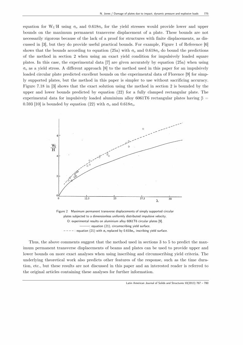
Figure 2 Maximum permanent transverse displacements of simply supported circular
plates subjected to a dimensionless uniformly distributed impulsive velocity. Ο: experimental results on aluminium alloy 6061T6 circular plates [9].
———: equation (21), circumscribing yield surface. – – – – : equation (21) with σo replaced by 0.618σo, inscribing yield surface.
Thus, the above comments suggest that the method used in sections 3 to 5 to predict the max-
imum permanent transverse displacements of beams and plates can be used to provide upper and lower bounds on more exact analyses when using inscribing and circumscribing yield criteria. The underlying theoretical work also predicts other features of the response, such as the time dura-tion, etc., but these results are not discussed in this paper and an interested reader is referred to the original articles containing these analyses for further information.

776 N, Jones / Damage of plates due to impact, dynamic pressure and explosive loads
Latin American Journal of Solids and Structures 10(2013) 767 – 780
Figure 3 Maximum permanent transverse displacements for aluminium alloy plates struck by a central mass versus factor K.
———: equation (26), – – – – : equation (26) with σo replaced by 0.618σo. Experimental results: ο; AA 6061T6 circular plate [11], ■, ◊; square plate made from AA 6082T6 and
AA 5083H12, respectively [12].
Experimental studies have been conducted on ductile metal plates for many of the cases re-ported in sections 3 to 5. For example, Florence’s [9] experimental results on aluminium alloy 6061T6 simply supported circular plates, which are subjected to a uniform impulsive loading are presented in Figure 2 and are compared with the predictions of equation (21).
It is observed that equation (4) for a fully clamped circular plate subjected to a central heavy mass impact and equation (10a) for a fully clamped square plate struck at the centre both can be written in the form
Wf /H = 1+ K( )1 2 − 1 , (26)
where K = 2Ω/π and K = Ω/2 for the two respective cases. Thus, equation (26) can be used for both cases and is plotted in Figure 3. Although three different aluminium alloys and two different experimental arrangements have been used to obtain the experimental test data [11, 12], it is evident that equation (26) (ie., equations (4) and (10a) with σo and 0.618σo) provide reasonable practical bounds on the maximum permanent transverse displacements. Equation (10a) for a fully clamped square plate struck by a mass and equation (25a) for a square plate subjected to a uni-formly distributed impulsive velocity both can be written in the form of equation (26), where K = Ω/2 and K = 2λ/3 for the two cases. Equation (26) is plotted in Figure 5 of Reference [2] and
N, Jones / Damage of plates due to impact, dynamic pressure and explosive loads 777
Latin American Journal of Solids and Structures 10(2013) 767 – 780
with σo and 0.618σo provides quite reasonable practical bounds for the experimental data on three different aluminium alloys [7, 12]. Now, equation (22) for an impulsively loaded fully clamped rectangular plate can be ex-pressed in the form
α1Wf /H = 1+α 2λ( )1 2 − 1, (27)
where
α1 = 2 1+ 1− ξo( ) 2 − ξo( ){ } / 3− ξo( ) (28a)
and
α 2 = 2ξ02 1−ξ0 +1/ 2 −ξ0( ){ } / 3 (28b)
Equation (27) with σo and 0.618σo is plotted in Figure 4 and compared with the experimental
data on aluminium alloy 6061T6 rectangular plates having aspect ratios β = , , and 1. Again the curves do almost bound the experimental results, although equation (27) with σo gives a good estimate for all of the experimental values.
The theoretical analyses in section 3 for the mass impact loading of plates are simplified by taking the striking mass as a point loading. However, the actual diameter of a mass, G, is re-tained in [5] for a fully clamped circular plate struck by a blunt-faced projectile. The comparisons in Figure 7.24 [3] reveal that the predictions of equation (4) and equation (4) with σo replaced by 0.618σo essentially bound the experimental data for the maximum permanent transverse dis-placements of fully clamped aluminium alloy circular plates [11] struck by large cylindrical masses travelling with impact velocities up to 4 m/s. It is shown that when retaining the influence of the striker radius ρ = a/R, where 2a is the diameter of a cylindrical projectile, that the accuracy of the bounds is improved.
The various equations can be used to compare the weights and other characteristics of the dif-ferent plates for a given loading condition and flow stress, σo. For example, equations (4) and (10a) for mass impact loaded fully clamped circular and square plates with the same surface areas (i.e., L / R = π 4 ) reveal that the dimensionless ratios Wf /H are the same when the thickness
of the circular plate is 4 π( )1 3 times the thickness of a square plate. Thus, Wf for a square
plate is π 4( )1 3 times the corresponding value for a circular plate. Moreover, the mass of a
square plate is π 4( )1 3 times the mass of a circular plate. Equations (19) and (25a) predict the dimensionless values of Wf /H for fully clamped circu-
lar and square plates when subjected to uniformly distributed impulsive velocity loadings over the entire exposed surface areas, where the associated dimensionless loadings, λ , are defined by equations (20) and (23). In this case, it turns out that the plates have the same masses and values

778 N, Jones / Damage of plates due to impact, dynamic pressure and explosive loads
Latin American Journal of Solids and Structures 10(2013) 767 – 780
of Wf /H when the thickness of the circular plate is 4 π( )1 4 times the thickness of the square
plate for given loading conditions and flow stress σo. However, if the surface areas are equal (i.e.,
4L2 = πR2 ) instead of the masses, then the thickness of the circular plate is 4 π( )1 3 times the square plate thickness to ensure that the values of Wf /H are equal.
For sufficiently severe external loadings then a plate might be perforated during a mass im-pact, or fail at the supports, for example, due to a pressure pulse or an impulsive loading. Refer-ence [13] contains some empirical equations for the perforation of aluminium alloy plating. The failure of plating due to blast loadings is usually tackled with the aid of a numerical scheme, alt-hough there are difficulties in specifying the correct conditions for the initiation of failure.
Figure 4: Equation (27) (———) and equation (27) with σo replaced by 0.618σo
(– – –) compared with experimental results on impulsively loaded fully clamped AA 6061T6 rectangular plates [7] (ο, ∆, +, □ are for β = , , and 1, respectively).
7 CONCLUSIONS
Theoretical formulae have been presented for the maximum permanent transverse displacements (or damage) of ductile plating having circular, square and rectangular shapes and subjected to mass impact, dynamic pressure and impulsive loadings. Reasonably good agreement has been found with the available experimental data on plates which are made from strain rate insensitive aluminium alloys. Thus, these simple formulae could be used for design or forensic purposes to
N, Jones / Damage of plates due to impact, dynamic pressure and explosive loads 779
Latin American Journal of Solids and Structures 10(2013) 767 – 780
predict the damage of plating under large dynamic loadings. The basic theoretical procedure can, in fact, be used for arbitrarily shaped plates which are subjected to a wide range of dynamic load-ings producing a large inelastic response.
This study has revealed a paucity of experimental data on the damage of ductile plating. This situation is also of concern for numerical schemes which introduce various idealisations in the calculations which require validation (eg., simplification of the boundary conditions and the characteristics of the external dynamic loading [14] and [15]). Acknowledgements The author is grateful to Mrs J. Jones for her secretarial assistance and to Mrs I. Arnot for her assistance with the figures. References [1] Jones, N., Impact Loading of Ductile Rectangular Plates, Proceedings 11th International
Conference on Structures Under Shock and Impact, Structures Under Shock and Impact X1, Tallin, Estonia, ed. N. Jones, C. A. Brebbia, U. Mander, WIT Press, pp. 71-81, 2010. Also WIT Transactions on The Built Environment, 113, 2010.
[2] Jones, N., Impact Loading of Ductile Rectangular Plates, Thin-Walled Structures, 50(1), pp. 68-75, 2012. DOI: 10.1016/j.tws.2011.09.006.
[3] Jones, N., Structural Impact, Cambridge University Press, pp. 575, 1st edition, 1989, Paper-back edition, 1997. 2nd edition, pp. 584, 2012. 1st edition translated into Chinese by Ping Jiang and Lili Wang, Sichuan Education Press, Chengdu, 1994.
[4] Jones, N., A Theoretical Study of the Dynamic Plastic Behavior of Beams and Plates with Finite-Deflections, International Journal of Solids and Structures, 7, pp. 1007-1029, 1971.
[5] Jones, N., On the Mass Impact Loading of Ductile Plates, Defence Science Journal, Defence Research and Development Organisation, India, 53(1), pp. 15-24, 2003.
[6] Jones, N., Hazard Assessments for Extreme Dynamic Loadings, Latin American Journal of Solids and Structures, 6(1), pp. 35-49, 2009.
[7] Jones, N., A Literature Review of the Dynamic Plastic Response of Structures, The Shock and Vibration Digest, 7(8), pp. 89-105, 1975.
[8] Jones, N., Impulsive Loading of a Simply Supported Circular Rigid-Plastic Plate, Journal of Applied Mechanics, 35(1), Transactions A.S.M.E., Series E, pp. 59-65, 1968.
[9] Florence, A. L., Circular Plate under a Uniformly Distributed Impulse, International Journal of Solids and Structures, 2, pp. 37-47, 1966.
[10] Jones, N., Uran, T. O. and Tekin, S. A., The Dynamic Plastic Behavior of Fully Clamped Rectangular Plates, International Journal of Solids and Structures, 6, pp. 1499-1512, 1970.
[11] Wen, H-M. and Jones, N., Experimental Investigation into the Dynamic Plastic Response and Perforation of a Clamped Circular Plate Struck Transversely by a Mass, proc. Inst.of Mechanical Engineers (London) 208(C2), pp. 113-137, 1994.
[12] Langseth, M. and Larsen, P. K., Dropped Objects’ Plugging Capacity of Aluminium Alloy Plates, International Journal of Impact Engineering, 15(3), pp. 225-241, 1994.

780 N, Jones / Damage of plates due to impact, dynamic pressure and explosive loads
Latin American Journal of Solids and Structures 10(2013) 767 – 780
[13] Jones, N. and Paik, J. K., Impact Perforation of Aluminium Alloy Plates, International Journal of Impact Engineering, 48, pp. 46-53, 2012. DOI:10.1016/j.ijimpeng.2011.05.007.
[14] Thornton, J., The Question of Credibility, Mechanical Engineering, ASME, pp. 40-45, May 2010.
[15] Jones, N., The Credibility of Predictions for Structural Design Subjected to Large Dynamic loadings Causing Inelastic Behaviour. International Journal of Impact Engineering, 53, pp. 106-114, 2013. DOI:10.1016/j.ijimpeng.2011.12.008.