Deflection of Laminated Composite Plates Using Dynamic ... fileDeflection of Laminated Composite...
12
International Journal of Physical Sciences and Engineering (IJPSE) Available online at http://ScienceScholar.us/journal/index.php/ijpse : http://dx.doi.org/10.21744/ijpse.v1i1.5 35 Deflection of Laminated Composite Plates Using Dynamic Relaxation Method Osama Mohammed Elmardi Suleiman a Article Info Abstract Received 10 January 2017 Accepted in revised form 12 February 2017 Approved 14 February 2017 Available online 15 February 2017 First – order orthotropic shear deformation equations for the nonlinearly elastic bending response of rectangular plates are introduced. Their solution using a computer program based on finite differences implementation of the Dynamic Relaxation (DR) method is outlined. The convergence and accuracy of the DR solutions for elastic large deflection response of isotropic, orthotropic, and laminated plates are established by comparison with various exact and approximate solutions. The present Dynamic Relaxation method (DR) coupled with finite differences method shows a fairly good agreement with other analytical and numerical methods used in the verification scheme. It was found that: The convergence and accuracy of the DR solution are dependent on several factors including boundary conditions, mesh size and type, fictitious densities, damping coefficients, time increment and applied load. Also, the DR large deflection program using uniform finite differences meshes can be employed in the analysis of different thicknesses for isotropic, orthotropic or laminated plates under uniform loads. All the comparison results for simply supported (SS4) edge conditions showed that deflection is almost dependent on the direction of the applied load or the arrangement of the layers. Keywords Deflection Laminated Composite Plates Dynamic Relaxation Method Copyright © 2017 the Author. Published by ScienceScholar Inc. This is an open access article under the CC-BY-SA license (https://creativecommons.org/licenses/by/4.0/) All rights reserved. Corresponding Author at: First Author, Department of Mechanical Engineering, Faculty of Engineering and Technology, Nile Valley University, Atbara, Sudan Email address : [email protected], [email protected] a Nile Valley University, Atbara, Sudan
Transcript of Deflection of Laminated Composite Plates Using Dynamic ... fileDeflection of Laminated Composite...

International Journal of Physical Sciences and Engineering (IJPSE)
Available online at http://ScienceScholar.us/journal/index.php/ijpse
: http://dx.doi.org/10.21744/ijpse.v1i1.5
35
Deflection of Laminated Composite Plates Using Dynamic Relaxation Method
Osama Mohammed Elmardi Suleiman a
Article Info Abstract
Received 10 January 2017
Accepted in revised form 12
February 2017
Approved 14 February 2017
Available online 15 February
2017
First – order orthotropic shear deformation equations for the
nonlinearly elastic bending response of rectangular plates are
introduced. Their solution using a computer program based on finite
differences implementation of the Dynamic Relaxation (DR) method
is outlined. The convergence and accuracy of the DR solutions for
elastic large deflection response of isotropic, orthotropic, and
laminated plates are established by comparison with various exact
and approximate solutions. The present Dynamic Relaxation
method (DR) coupled with finite differences method shows a fairly
good agreement with other analytical and numerical methods used in
the verification scheme. It was found that: The convergence and
accuracy of the DR solution are dependent on several factors
including boundary conditions, mesh size and type, fictitious
densities, damping coefficients, time increment and applied load.
Also, the DR large deflection program using uniform finite
differences meshes can be employed in the analysis of different
thicknesses for isotropic, orthotropic or laminated plates under
uniform loads. All the comparison results for simply supported (SS4)
edge conditions showed that deflection is almost dependent on the
direction of the applied load or the arrangement of the layers.
Keywords Deflection
Laminated Composite Plates
Dynamic Relaxation Method
Copyright © 2017 the Author. Published by ScienceScholar Inc. This is an
open access article under the CC-BY-SA license
(https://creativecommons.org/licenses/by/4.0/)
All rights reserved.
Corresponding Author at: First Author,
Department of Mechanical Engineering, Faculty of Engineering and Technology, Nile Valley University,
Atbara, Sudan
Email address : [email protected], [email protected]
a Nile Valley University, Atbara, Sudan

International Journal of Physical Sciences and Engineering (IJPSE)
IJPSE Vol. 1 No. 1, January-April 2017, pages: 35~46
36
ملخص
. يتم تأطير حل هذه (FSDT)في هذا البحث تم استخدام معادالت تشوهات القص ذات الرتبة األولي المتباينة الخواص في اتجاهين متعامدين
. يتم تأسيس (DR)المعادالت بإستخدام برنامج حاسوب مؤسس على تطبيق الفروقات المحددة باالزدواج مع أسلوب االسترخاء الديناميكي
تعامدين، أللواح ذات انحرافات كبيرة مرنة متشابهة الخواص، متبانية الخواص فى أتجاهين م (DR)تقارب ودقة حلول اإلسترخاء الديناميكي
المقترن بأسلوب (DR)وألواح شرائحية ذات عدة طبقات بمقارنة النتائج بعدة حلول مضبوطة وتقريبية. يظهر أسلوب اإلسترخاء الديناميكي
الفروقات المحددة توافقاً مقبوالً مع أساليب تحليلية وعددية متباينة.
ناميكي يعتمد على عدة عوامل تشمل الشروط الحدية، التقسيمات الشبكية للوح وجد في هذه الدراسة أن تقارب ودقة حل أسلوب اإلسترخاء الدي
رخاء فى أتجاهين متعامدين ونوعها، الكثافات الوهمية، معامالت االخماد، الزيادة الزمنية والحمل المسلط. أيضاً يمكن إستخدام برنامج اإلست
الخواص فى أتجاهين متعامدين، وألواح ذات عدة طبقات تحت أحمال منتظمة فى تحليل ألواح متشابهة الخواص، ومتباينة (DR)الديناميكي
لثخانات متباينة.
أوضحت جميع نتائج المقارنة لحالة اإلسناد البسيط الطرفي أن اإلنحراف يعتمد اساسياً على أتجاه الحمل المسلط أو ترتيبة الطبقات.
Notation
a, b plate side lengths in x and y directions respectively.
6,2,1, jiA ji Plate in plane stiffness.
5544 , AA Plate transverse shear stiffness.
6,2,1, jiD ji Plate flexural stiffness.
yxyx Mid – plane direct and shear strains
zyzx , Mid – plane transverse shear strains.
1221 ,, GEE In – plane elastic longitudinal, transverse and shear moduli.
2313,GG Transverse shear moduli in the x – z and y – z planes respectively.
yxyx MMM ,, Stress couples.
yxyx MMM ,, Dimensionless stress couples.
yxyx NNN ,, Stress resultants.
yxyx NNN ,, Dimensionless stress resultants.
q Dimensionless transverse pressure.
yx QQ , Transverse shear resultants.
vu, In – plane displacements.
w Deflections
w Dimensionless deflection
zyx ,, Cartesian co – ordinates.
t Time increment
, Rotations of the normal to the plate mid – plane
yx Poisson’s ratio
,,,, wvu In plane, out of plane and rotational fictitious densities.
zxyx ,, Curvature and twist components of plate mid – plane
Introduction Composites were first considered as structural materials a little more than half a century ago. From that
time to now, they have received increasing attention in all aspects of material science, manufacturing
technology, and theoretical analysis.
The term composite could mean almost any thing if taken at face value, since all materials are composites
of dissimilar subunits if examined at close enough details. But in modern engineering materials, the term
usually refers to a matrix material that is reinforced with fibers. For instance, the term “FRP” which refers to
Fiber Reinforced plastic, usually indicates a thermosetting polyester matrix containing glass fibers, and this
particular composite has the lion’s share of today commercial market.

IJPSE Contents lists available at ScienceScholar
Deflection of Laminated Composite Plates Using Dynamic Relaxation Method
(Osama Mohammed Elmardi Suleiman)
37
In the present work, a numerical method known as Dynamic Relaxation (DR) coupled with finite
differences is used. The DR method was first proposed in 1960s and then passed through a series of studies to
verify its validity by Turvey and Osman Refs. [4], [8] and [9] and Rushton [2], Cassel and Hobbs [10], and
Day [11]. In this method, the equations of equilibrium are converted to dynamic equations by adding
damping and inertia terms. These are then expressed in finite difference form and the solution is obtained
through iterations. The optimum damping coefficient and time increment used to stabilize the solution
depend on a number of factors including the matrix properties of the structure, the applied load, the boundary
conditions and the size of the mesh used.
Numerical techniques other than the DR include finite element method, which widely used in the present
studies i.e. of Damodar R. Ambur et al [12], Ying Qing Huang et al [13], Onsy L. Roufaeil et al [14]… etc.
In a comparison between the DR and the finite element method, Aalami [15] found that the computer time
required for finite element method is eight times greater than for DR analysis, whereas the storage capacity
for finite element analysis is ten times or more than that for DR analysis. This fact is supported by putcha and
Reddy [16] who noted that some of the finite element formulations require large storage capacity and
computer time. Hence, due to less computations and computer time involved in the present study. The DR
method is considered more efficient than the finite element method. In another comparison Aalami [15]
found that the difference in accuracy between one version of finite element and another may reach a value of
10% or more, whereas a comparison between one version of finite element method and DR showed a
difference of more than 15%. Therefore, the DR method can be considered of acceptable accuracy. The only
apparent limitation of DR method is that it can only be applied to limited geometries. However, this
limitation is irrelevant to rectangular plates which are widely used in engineering applications.
The Dynamic Relaxation (DR) program used in this paper is designed for the analysis of rectangular
plates irrespective of material, geometry, edge conditions. The functions of the program are to read the file
data; compute the stiffness of the laminate, the fictitious densities, the velocities and displacements and the
mid – plane deflections and stresses; check the stability of the numerical computations, the convergence of
the solution, and the wrong convergence; compute through – thickness stresses in direction of plate axes; and
transform through – thickness stresses in the lamina principal axes.
The convergence of the DR solution is checked at the end of each iteration by comparing the velocities
over the plate domain with a predetermined value which ranges between 910
for small deflections and 610for large deflections. When all velocities are smaller than a predetermined value, the solution is deemed
converged and consequently the iterative procedure is terminated. Sometimes DR solution converges to an
invalid solution. To check for that the profile of the variable is compared with an expected profile over the
domain. For example, when the value of the function on the boundaries is zero, and it is expected to increase
from edge to center, then the solution should follow a similar profile. When the computed profile is different
from the expected values, the solution is considered incorrect and can hardly be made to converge to the
correct value by altering the damping coefficients and time increment. Therefore, the boundary conditions
should be examined and corrected if they are improper.
The errors inherent in the DR technique include the discretization error which is due to the replacement of
a continuous function with a discrete function, and there is an additional error because the discrete equations
are not solved exactly due to the variations of the velocities from the edge of the plate to the center. Finer
meshes reduce the discretization error, but increase the round – off error due to the large number of
calculations involved.
Methods and Analysis Large Deflection Theory
The equilibrium, strain, constitutive equations and boundary conditions are introduced below without
derivation
Equilibrium Theory
0
y
N
x
N yxx
0
y
N
x
N yyx
International Journal of Physical Sciences and Engineering (IJPSE)
IJPSE Vol. 1 No. 1, January-April 2017, pages: 35~46
38
1022
22
2
2
q
y
Q
x
Q
y
wN
yx
wN
x
wN
yxyyxx
0
x
yxx Qy
M
x
M
0
y
yyxQ
y
M
x
M
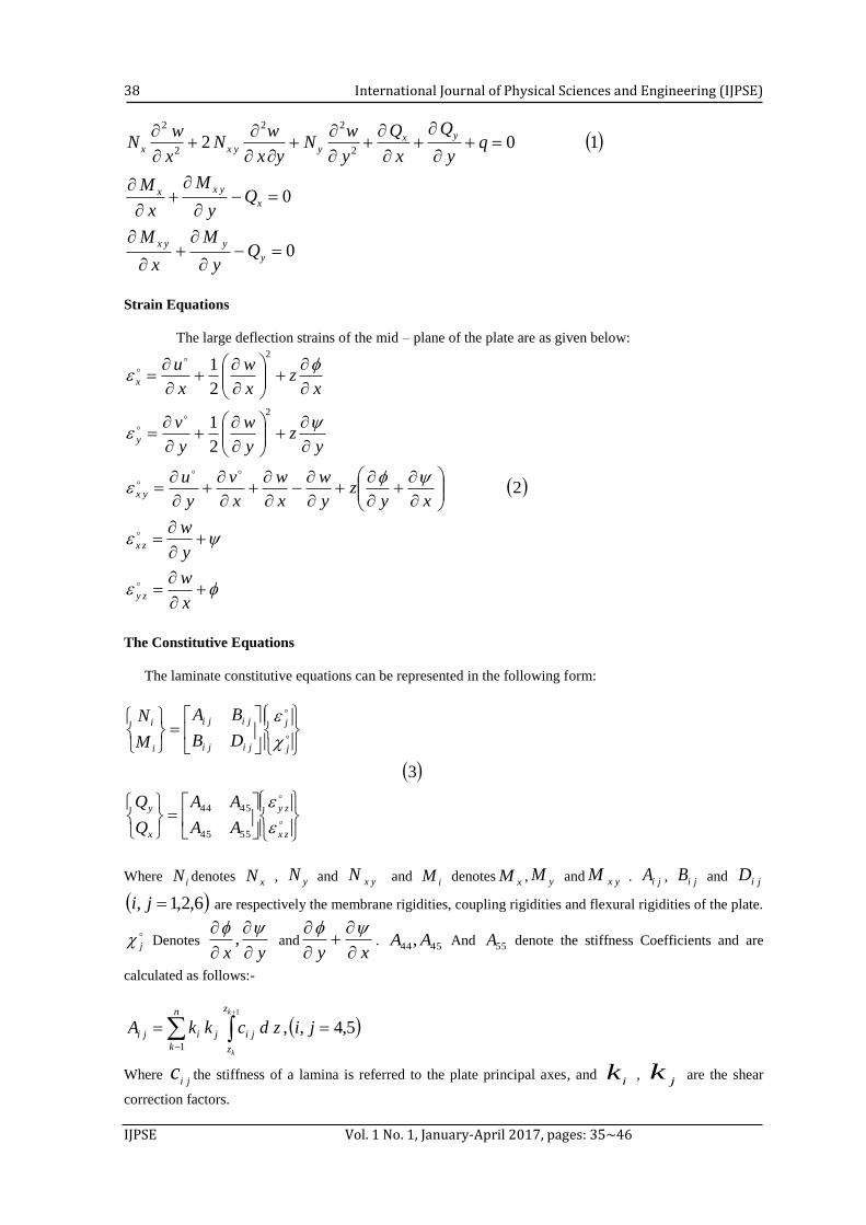
Strain Equations
The large deflection strains of the mid – plane of the plate are as given below:
xz
x
w
x
ux
2
2
1
yz
y
w
y
vy
2
2
1
2
xyz
y
w
x
w
x
v
y
uyx
y
wzx
x
wzy
The Constitutive Equations
The laminate constitutive equations can be represented in the following form:
zx
zy
x
y
j
j
jiji
jiji
i
i
AA
AA
Q
Q
DB
BA
M
N
5545
4544
3
Where iN denotes xN , yN and yxN and iM denotes xM , yM and yxM . jiA , jiB and jiD
6,2,1, ji are respectively the membrane rigidities, coupling rigidities and flexural rigidities of the plate.
j Denotes
yx
, and
xy
. 4544, AA And 55A denote the stiffness Coefficients and are
calculated as follows:-
1
5,4,,1
k
k
z
z
ji
n
k
jiji jizdckkA
Where ji
c the stiffness of a lamina is referred to the plate principal axes, and i
k , j
k are the shear
correction factors.
IJPSE Contents lists available at ScienceScholar
Deflection of Laminated Composite Plates Using Dynamic Relaxation Method
(Osama Mohammed Elmardi Suleiman)
39
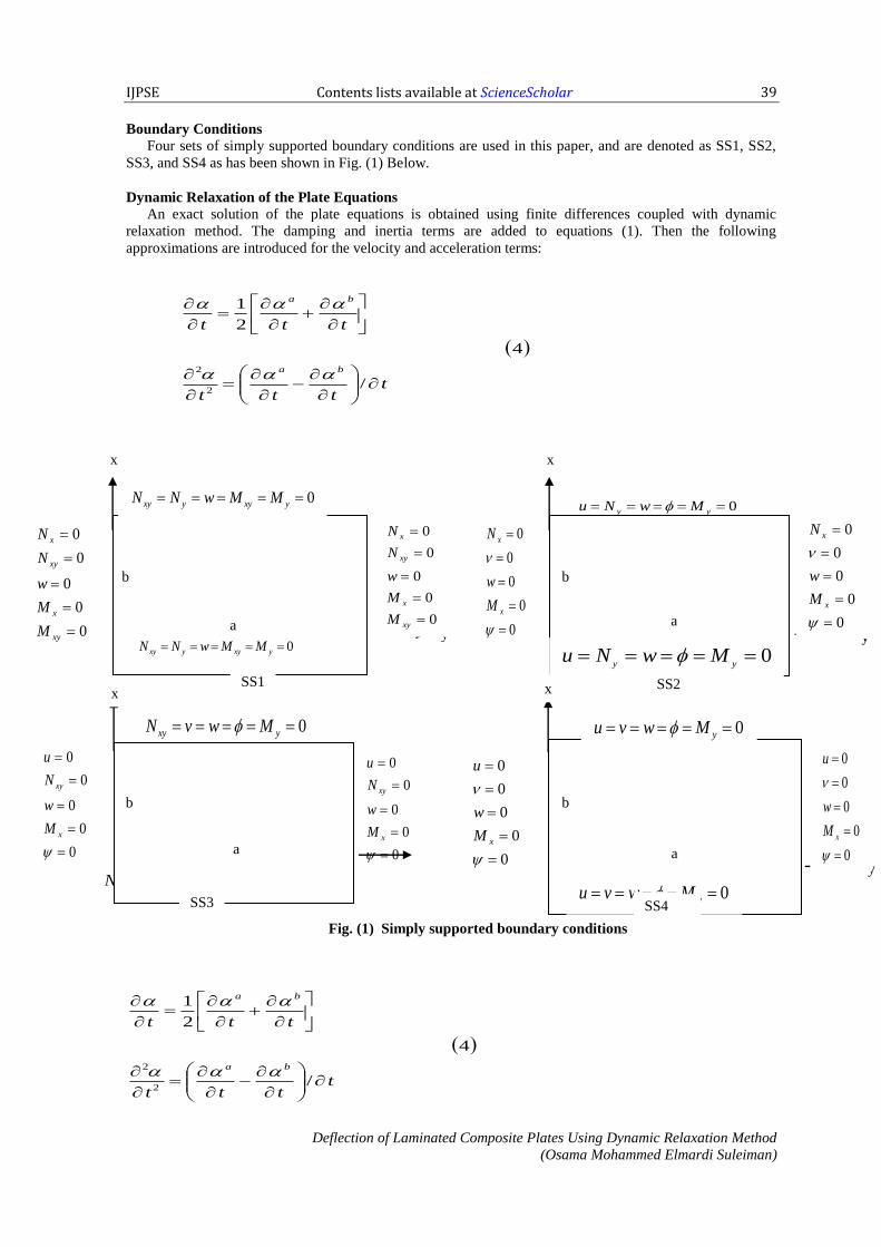
Boundary Conditions
Four sets of simply supported boundary conditions are used in this paper, and are denoted as SS1, SS2,
SS3, and SS4 as has been shown in Fig. (1) Below.
Dynamic Relaxation of the Plate Equations
An exact solution of the plate equations is obtained using finite differences coupled with dynamic
relaxation method. The damping and inertia terms are added to equations (1). Then the following
approximations are introduced for the velocity and acceleration terms:
tttt
ttt
ba
ba
/
4
2
1
2
2
Fig. (1) Simply supported boundary conditions
tttt
ttt
ba
ba
/
4
2
1
2
2
y 0
0
0
0
0
x
xy
M
w
N
u
0
0
0
0
0
x
x
M
w
N
0
0
0
0
0
xy
x
xy
x
M
M
w
N
N
0 yy MwNu
a y y
x x
SS2
b
SS1
0 yxyyxy MMwNN
a
b
0
0
0
0
0
x
xy
M
w
N
u
0 yxy MwvN
SS3
0 yxy MwvN
a
b
0 yxyyxy MMwNN 0
yyMwNu
x
0
0
0
0
0
xM
w
u
y
x
0 yMwvu
a
b
0
0
0
0
0
xy
x
xy
x
M
M
w
N
N
0
0
0
0
0
x
x
M
w
N
0
0
0
0
0
xM
w
u
0 yMwvu
SS4
SS2
SS3

International Journal of Physical Sciences and Engineering (IJPSE)
IJPSE Vol. 1 No. 1, January-April 2017, pages: 35~46
40
In which ,,,, wvu . Hence equations (1) become:
y
N
x
N
u
t
t
uk
kt
u yxx
b
u
u
a
*
*1
1
1
y
N
x
N
u
t
t
vk
kt
v yyxb
v
v
a
*
*1
1
1
5211
12
22
2
2*
*
q
y
Q
x
Q
y
wN
yx
wN
x
wN
t
t
wk
kt
w yxyyxx
w
b
w
w
a
x
yxyba
Qy
M
x
Mt
tk
kt
*
*1
1
1
y
yyxba
Qy
M
x
Nt
tk
kt
*
*1
1
1
The superscripts a and b in equations (4) and (5) refer respectively to the values of velocities after and before
the time increment t and1*
2
1 tkk . The displacements at the end of each time increment, t ,
are evaluated using the following integration procedure:
6t
tb
ba
Thus equations (5), (6), (2) and (3) constitute the set of equations for solution. The DR procedure operates as
follows:
(1) Set initial conditions.
(2) Compute velocities from equations (5).
(3) Compute displacement from equation (6).
(4) Apply displacement boundary conditions.
(5) Compute strains from equations (2).
(6) Compute stress resultants and stress couples from equations (3).
(7) Apply stress resultants and stress couples boundary conditions.
(8) Check if velocities are acceptably small (say610
).
(9) Check if the convergence criterion is satisfied, if it is not repeat the steps from 2 to 8.
It is obvious that this method requires five fictitious densities and a similar number of damping
coefficients so as the solution will be converged correctly.
Verification of the Numerical Technique
Table (1) shows deflections, stress resultants and stress couples in simply supported in – plane free (SS2)
isotropic plate. The present results have been computed with 66 uniform meshes. These results are in a
fairly good agreement with those of Aalami et al [1] using finite difference method (i.e. for deflections, the
difference ranges between 0.35% at 8.20q and 0 % as the pressure is increased to 97). A similar
comparison between the two results is shown in Table (2) for simply supported (SS3) condition. It is apparent
that the center deflections, stress couples and stress resultants agree very well. The mid – side stress
resultants do not show similar agreement whilst the corner stress resultants show considerable differences.
This may be attributed to the type of mesh used in each analysis. A set of thin plate results comparisons
presented here with Rushton [2] who employed the DR method coupled with finite olifferences. The present
results for simply supported (SS4) square plates were computed for two thickness ratios using a 88
uniform mesh are listed in table (3). In this instant, the present results differ slightly from those found in Ref.
[2]. Another comparison for simply supported (SS4) square isotropic plates subjected to uniformly
distributed loads are shown in Tables (4) and (5) respectively for deflection analysis of thin and moderately
thick plates. In this comparison, it is noted that, the centre deflection of the present DR analysis, and those of
Azizian and Dawe [3] who employed the finite strip method are in fairly good agreement (i.e. with a
maximum error not exceeding 0.09%).

IJPSE Contents lists available at ScienceScholar
Deflection of Laminated Composite Plates Using Dynamic Relaxation Method
(Osama Mohammed Elmardi Suleiman)
41
A large deflection comparison for orthotropic plates was made with the DR program. The results are
compared with DR results of Turvey and Osman [4], Reddy’s [5], and Zaghloul et al results [6]. For a thin
uniformly loaded square plate made of material I which its properties are stated in Table (6) and with simply
supported in – plane free (SS2) edges. The center deflections are presented in Table (7) where DR showed a
good agreement with the other three.
A large deflection comparison for laminated plates was made by recomposing sun and chin’s results [7]
for [ 44 0/90 ] using the DR program and material II which its properties are cited in Table (6). The results
were obtained for quarter of a plate using a 55 square mesh, with shear correction factors
6/52
5
2
4 kk . The analysis was made for different boundary conditions and the results were shown in
Tables (8), and (9) as follows: The present DR deflections of two layer antisymmetric cross – ply simply
supported in – plane fixed (SS4) are compared with DR results of Turvey and Osman [8] and with sun and
chin’s values for a range of loads as shown in Table (4-8). The good agreement found confirms that for
simply supported (SS4) edge conditions, the deflection depends on the direction of the applied load or the
arrangement of the layers. Table (9) shows a comparison between the present DR, and DR Ref. [8] results,
which are approximately identical. The difference between laminates 90/0 and 0/90 at
5/ ab is 0.3% whilst it is 0% when 1/ ab .
The comparison made between DR and alterative techniques show a good agreement and hence the
present DR large deflection program using uniform finite difference meches can be employed with
confidence in the analysis of moderately thick and thin flat isotropic, orthotropic or laminated plates under
uniform loads. The program can be used with the same confidence to generate small deflection results.
Table (1) comparison of present DR, Aalami and Chapman’s [1] large deflection results for simply
supported (SS2) square isotropic plate subjected to uniform pressure 3.0,02.0/ vah
q S cw
2
1
y
x
M
M
2
1
y
x
N
N
20.8 1
2
0.7360
0.7386
0.7357
0.7454
0.7852
0.8278
41.6 1
2
1.1477
1.1507
1.0742
1.0779
1.8436
1.9597
63.7 1
2
1.4467
1.4499
1.2845
1.2746
2.8461
3.0403
97.0 1
2
1.7800
1.7800
1.4915
1.4575
4.1688
4.4322
S (1): present DR results ( 66 uniform mesh over quarter of the plate)
S (2): Ref. [1] results ( 66 graded mesh over quarter of the plate)
Table (2) Comparison of present DR, Aalami and Chapman’s [1] large
deflection results for simply supported (SS3) square isotropic plate subjected to uniform pressure
3.0,02.0/ vah
q S cw
1
1
y
x
M
M
1
1
y
x
N
N
3
2
y
x
N
N
2
3
y
x
N
N
4
4
y
x
N
N
20.8 1
2
0.5994
0.6094
0.6077
0.6234
1.0775
1.0714
0.2423
0.2097
1.1411
1.1172
0.1648
0.2225
41.6 1
2
0.8613
0.8783
0.8418
0.8562
2.2435
2.2711
0.5405
0.4808
2.4122
2.4084
0.3177
0.4551
0,2
11 zayx

International Journal of Physical Sciences and Engineering (IJPSE)
IJPSE Vol. 1 No. 1, January-April 2017, pages: 35~46
42
63.7 1
2
1.0434
1.0572
0.9930
1.0114
3.3151
3.3700
0.8393
0.7564
3.6014
3.6172
0.4380
0.6538
97.0 1
2
1.2411
1.2454
1.1489
1.1454
4.7267
4.8626
1.2604
1.1538
5.1874
2.2747
0.5706
0.9075
S (1): present DR results ( 66 uniform mesh over quarter of the plate)
S (2): Ref. [1] results ( 66 graded mesh over quarter of the plate)
0)4(;0,2
1,0)3(;0,
2
1)2(;0,
2
11 zyxzayxzyaxzayx
Table (3) Comparison of present DR, and Rushton’s [2] large deflection results for simply supported
(SS4) square isotropic plate subjected to uniform pressure 3.0v
q S cw 11
8.2
1
2
3
0.3172
0.3176
0.2910
2.3063
2.3136
2.0900
29.3
1
2
3
0.7252
0.7249
0.7310
5.9556
5.9580
6.2500
91.6
1
2
3
1.2147
1.2147
1.2200
11.3180
11.3249
11.4300
293.0
1
2
3
1.8754
1.8755
1.8700
20.749
20.752
20.820
S (1): present DR results ( 88;02.0/ ah uniform mesh over quarter of the plate)
S (2): present DR results ( 88;01.0/ ah uniform mesh over quarter of the plate)
S (3): Ref. [2] results (thin plate 88 uniform mesh over quarter of the plate)
hzayx2
1,
2
11
Table (4) Comparison of the present DR, and Azizian and Dawe’s [3] large deflection results for thin
shear deformable simply supported (SS4) square isotropic plate subjected to uniform pressure
3.0,01.0/ vah
q S cw
9.2 1
2
0.34693
0.34677
36.6 1
2
0.80838
0.81539
146.5 1
2
1.45232
1.46250
586.1 1
2
2.38616
2.38820
S (1): present DR results ( 66 uniform mesh over quarter of the plate)
S (2): Azizian and Dawe [3] results.

IJPSE Contents lists available at ScienceScholar
Deflection of Laminated Composite Plates Using Dynamic Relaxation Method
(Osama Mohammed Elmardi Suleiman)
43
Table (5) Comparison of the present DR, and Azizian and Dawe’s [3] large deflection results for
moderately thick shear deformable simply supported (SS4) square isotropic plates subjected to
uniform pressure 3.0,05.0/ vah
q S cw
0.92 1
2
0.04106
0.04105
4.6 1
2
0.19493
0.19503
6.9 1
2
0.27718
0.27760
9.2 1
2
0.34850
0.34938
S (1): present DR results ( 66 uniform mesh over quarter of the plate)
S (2): Azizian and Dawe [3] results.
Table (6) Material properties used in the orthotropic and laminated plate comparison analysis.
Material 21 / EE 22 / EG 213 / EG
223 / EG 12 2
5
2
4 kkSCF
I 2.345 0.289 0.289 0.289 0.32 6/5
II 14.3 0.5 0.5 0.5 0.3 6/5
Table (7) Comparison of present DR, DR results of Ref. [4], finite element results Ref. [5] and
experimental results Ref. [6] for a uniformly loaded simply supported (SS2) square orthotropic plate
made of material I 0115.0/ ah
q 1cw 2cw 3cw 4cw
17.9 0.5859 0.5858 0.58 0.58
53.6 1.2710 1.2710 1.30 1.34
71.5 1.4977 1.4977 1.56 1.59
89.3 1.6862 1.6862 1.74 1.74
S (1): present DR results ( 55 uniform non – interlacing mesh over quarter of the plate).
S (2): DR results of Ref. [4].
S (3): Reddy’s finite element results [5].
S (4): Zaghloul’s and Kennedy’s Ref. [6] experimental results as read from graph.
Table (8) Deflection of the center of a two – layer anti symmetric cross ply simply supported in – plane
fixed (SS4) strip under uniform pressure 01.0/,5/ ahab
q S 90/01w 0/902w 0jiBw 1% 2% 3%
81
8
2
3
0.6851
0.6824
0.6800
0.2516
0.2544
0.2600
0.2961
131.4
130.5
- 15.0
- 14.1
172.3
168.2
33
8
2
3
0.8587
0.8561
0.8400
0.3772
0.3822
0.3900
0.4565
88.1
87.5
- 17.4
- 16.3
127.7
124.0

International Journal of Physical Sciences and Engineering (IJPSE)
IJPSE Vol. 1 No. 1, January-April 2017, pages: 35~46
44
22
8
2
3
1.0453
1.0443
1.0400
0.5387
0.5472
0.5500
0.6491
61.0
60.9
- 17.0
- 15.7
94.0
90.8
801
8
2
3
1.1671
1.1675
1.1500
0.6520
0.6630
0.6600
0.7781
50.0
50.0
- 16.2
- 14.8
79.0
76.1
S (1): present DR results
S (2): DR results Ref. [8].
S (3): Values determined from sun and chin’s results Ref. [7].
(1): www /100 1
(2): www /100 2
(3): 221 /100 www
Table (9) Center deflection of two – layer anti – symmetric cross – ply simply supported in – plane free
(SS1) plate under uniform pressure and with different aspect ratios 18;01.0/ qah .
ab / S 90/01w 0/902w 0jiBw 1% 2% 3%
2.5 1
2
0.8325
0.8328
0.8422
0.8424
0.3907
0.3907
113.1
113.2
115.6
115.6
- 1.15
- 1.1
2.0 1
2
0.7707
0.7712
0.7796
0.7799
0.3807
0.3807
102.4
102.6
104.8
104.9
- 1.14
- 1.1
1.75 1
2
0.7173
0.7169
0.7248
0.7251
0.3640
0.3640
97.0
97.0
99.1
99.2
- 1.0
- 1.1
1.5 1
2
0.6407
0.6407
0.6460
0.6455
0.3335
0.3325
92.1
92.7
93.7
94.1
- 0.82
- 0.70
1.25 1
2
0.5324
0.5325
0.5346
0.5347
0.2781
0.2782
91.4
91.4
92.2
92.2
- 0.4
- 0.4
1.0 1
2
0.3797
0.3796
0.3797
0.3796
0.1946
0.1949
95.1
94.8
95.1
94.8
0.0
0.0
S (1): present DR results
S (2): DR results Ref. [8].
(1): www /100 1
(2): www /100 2
(3): 221 /100 www
Conclusion A Dynamic relaxation (DR) program based on finite differences has been developed for large deflection
analysis of rectangular laminated plates using first order shear deformation theory (FSDT). The
displacements are assumed linear through the thickness of the plate. A series of new results for uniformly
loaded thin, moderately thick, and thick plates with simply supported edges have been presented. Finally a
series of numerical comparisons have been undertaken to demonstrate the accuracy of the DR program.
These comparisons show the following:-
1. The convergence of the DR solution depends on several factors including boundary conditions,
meshes size, fictitious densities and applied load.
2. The DR large deflection program using uniform finite differences meshes can be employed with
confidence in the analysis of moderately thick and flat isotropic, orthotropic or laminated plates under
uniform loads.
3. The DR program can be used with the same confidence to generate small deflection results.
4. The time increment is a very important factor for speeding convergence and controlling numerical
computations. When the increment is too small, the convergence becomes tediously slow; and when it

IJPSE Contents lists available at ScienceScholar
Deflection of Laminated Composite Plates Using Dynamic Relaxation Method
(Osama Mohammed Elmardi Suleiman)
45
is too large, the solution becomes unstable. The proper time increment in the present study is taken as
0.8 for all boundary conditions.
5. The optimum damping coefficient is that which produces critical motion. When the damping
coefficients are large, the motion is over – damped and the convergence becomes very slow. At the
other hand when the coefficients are small, the motion is under – damped and can cause numerical
instability. Therefore, the damping coefficients must be selected carefully to eliminate under –
damping and over – damping.
Acknowledgements My deep and sincere gratitude were presented to God for having granted me the ability and the
opportunity to complete this paper. I would also like to thank my former lecturers and my friends for their
support, their patience, their contribution, and their valuable input, therefore, this article could be completed.
I would also thank Maria as advisor as well as editor in chief of SS who has reviewed and approved this
study to be published.
References [1] Aalami , B. and Chapman J.C. “ large deflection behavior of rectangular orthotropic plates under
transverse and in – plane loads”, proceedings of the institution of civil Engineers, (1969), 42, pp. (347 –
382).
[2] Rushton K. R., “large deflection of variable – thickness plates”, International journal of mech. Sciences,
vol. 10, (1968), pp. (723 – 735).
[3] Azizian Z. G. and Dawe D.J., “Geometrically Non – linear analysis of rectangular Mindlin plates using
the finite strip method”, computers and structures, vol.22, No.3, (1985), pp. (523 – 436).
[4] Turvey G.J. and Osman M.Y., “ large deflection analysis of orthotropic Mindlin plates, proceedings of
the 12th Energy resources technical conference and exhibition, Houston, Texas (1989), pp.(163 – 172).
[5] Reddy J.N., ‘Energy and variation methods in applied mechanics’, John Wiley and sons, New York,
(1984), pp. (379 – 387).
[6] Zaghloul S.A. and Kennedy J.B., “Nonlinear behavior of symmetrically laminated plates”, Journal of
applied mechanics, vol.42, (1975), pp. (234 – 236).
[7] Sun C.T. and Chin H., “on large deflection effects in unsymmetrical cross – ply composite laminates”,
Journal of composite materials, vol.22 (1988), pp. (1045 – 1059).
[8] Turvey G.J. and Oman M.y., “large deflection effects in anti symmetric cross – ply laminated strips and
plates”, I.H. Marshall, composite strictures, vol.6, paisley college, Scotland, Elsevier science publishers,
(1991), pp. (397 – 413).
[9] Turvey G. J. and Osman M. Y., ‘Elastic large deflection analysis of isotropic rectangular Mindlin
plates’, International journal of mechanical sciences, vol. 22, (1990). pp. (1 – 14).
[10] Cassel A.C. and Hobbs R.E., ‘Numerical Stability of dynamic relaxation analysis of nonlinear
structures’,
[11] Day A.S., ’An Introduction to dynamic relaxation’, the engineer, vol. 219, No. 5668, (1965), pp. (218 -
221).
[12] Damodar R. Ambur, Navin Jounky, Mark Hilburger, Carlos G. Davila,’ Progressive failure analysis of
compression loaded composite Curved panels with and without Cutouts,’ composite structures, vol.65,
(2004), pp. (143 – 155).
[13] Ying Qing Huang, Shenglin Di, Chang Chun Wu, and Huiya Sun, ’Bending analysis of composite
laminated plates using a partially hybrid stress element with interlaminar continuity’, computer and
structures, vol.80, (2002), pp. (403 – 410).
[14] Onsy L. Roufaeil, Thanh Tran – Cong,’ finite strip elements for laminated composite plates with
transverse shear strain discontinuities’, composite structure, vol. 56, (2002) , pp. (249 – 258).
[15] Aalami B., ‘Large deflection of elastic plates under patch loading’, Journal of structural division,
ASCE, vol. 98, No. ST 11, (1972), pp. (2567 – 2586).
[16] Putcha N.S. and Reddy J.N., ‘A refined mixed shear flexible finite element for the non – linear analysis
of laminated plates,’ computers and structures, vol. 22, No. 4, (1986), pp. (529 – 538).

International Journal of Physical Sciences and Engineering (IJPSE)
IJPSE Vol. 1 No. 1, January-April 2017, pages: 35~46
46
Biography of Author
Osama Mohammed Elmardi was born in Atbara, Sudan in 1966. He received his
diploma degree in mechanical engineering from Mechanical Engineering
College, Atbara, Sudan in 1990. He also received a bachelor degree in
mechanical engineering from Sudan University of science and technology –
Faculty of engineering in 1998, and a master degree in solid mechanics from
Nile valley university (Atbara, Sudan) in 2003. He contributed in teaching some
subjects in other universities such as Red Sea University (Port Sudan, Sudan),
Kordofan University (Obayed, Sudan), Sudan University of Science and
Technology (Khartoum, Sudan) and Blue Nile university (Damazin, Sudan). In
addition he supervised more than hundred and fifty under graduate studies in
diploma and B.Sc. levels and about fifteen master theses. He is currently an
assistant professor in department of mechanical engineering, Faculty of
Engineering and Technology, Nile Valley University. His research interest and
favourite subjects include structural mechanics, applied mechanics, control
engineering and instrumentation, computer aided design, design of mechanical
elements, fluid mechanics and dynamics, heat and mass transfer and hydraulic
machinery. He works also as a consultant and a technical manager of Al –
Kamali workshops group in Atbara – Sudan old and new industrial areas.