DALI / EtherNet/IP - Converter - ADFWeb.com Gateway...
43
Industrial Electronic Devices ADFweb.com Srl – IT31010 – Mareno – Treviso INFO: www.adfweb.com Phone +39.0438.30.91.31 User Manual DALI / EtherNet/IP Document code: MN67840_ENG Revision 1.001 Pagina 1 di 43 User Manual Revision 1.001 English DALI / EtherNet/IP - Converter (Order Code: HD67840-B2-Y, HD67840-B2-N) for Website information: www.adfweb.com?Product=HD67840 for Price information: www.adfweb.com?Price=HD67840-B2 Benefits and Main Features: Very easy to configure Electrical isolation Temperature range: -40°C/85°C (-40°F/185°F) For others DALI products, see also the following links: Converter DALI to www.adfweb.com?Product=HD67832 (BACnet/IP Master) www.adfweb.com?Product=HD67833 (BACnet/IP Slave) www.adfweb.com?Product=HD67839 (Ethernet) www.adfweb.com?Product=HD67844 (Modbus TCP Master) www.adfweb.com?Product=HD67845 (Modbus TCP Slave) www.adfweb.com?Product=HD67848 (PROFINET) www.adfweb.com?Product=HD67849 (SNMP Manager) www.adfweb.com?Product=HD67850 (SNMP Agent) Do you have an your customer protocol? www.adfweb.com?Product=HD67003 Do you need to choose a device? do you want help? www.adfweb.com?Cmd=helpme User Manual
Transcript of DALI / EtherNet/IP - Converter - ADFWeb.com Gateway...
Industrial Electronic Devices
ADFweb.com Srl – IT31010 – Mareno – Treviso INFO: www.adfweb.com Phone +39.0438.30.91.31
User Manual DALI / EtherNet/IP
Document code: MN67840_ENG Revision 1.001 Pagina 1 di 43
User Manual Revision 1.001 English
DALI / EtherNet/IP - Converter (Order Code: HD67840-B2-Y, HD67840-B2-N)
for Website information:
www.adfweb.com?Product=HD67840
for Price information:
www.adfweb.com?Price=HD67840-B2
Benefits and Main Features:
Very easy to configure
Electrical isolation
Temperature range: -40°C/85°C (-40°F/185°F)
For others DALI products, see also the following links:
Converter DALI to www.adfweb.com?Product=HD67832 (BACnet/IP Master) www.adfweb.com?Product=HD67833 (BACnet/IP Slave) www.adfweb.com?Product=HD67839 (Ethernet) www.adfweb.com?Product=HD67844 (Modbus TCP Master) www.adfweb.com?Product=HD67845 (Modbus TCP Slave) www.adfweb.com?Product=HD67848 (PROFINET) www.adfweb.com?Product=HD67849 (SNMP Manager)
www.adfweb.com?Product=HD67850 (SNMP Agent)
Do you have an your customer protocol? www.adfweb.com?Product=HD67003
Do you need to choose a device? do you want help? www.adfweb.com?Cmd=helpme
User Manual
Industrial Electronic Devices
ADFweb.com Srl – IT31010 – Mareno – Treviso INFO: www.adfweb.com Phone +39.0438.30.91.31
User Manual DALI / EtherNet/IP
Document code: MN67840_ENG Revision 1.001 Pagina 2 di 43
INDEX:
Page
INDEX 2
UPDATED DOCUMENTATION 2
REVISION LIST 2
WARNING 2
TRADEMARKS 2
SECURITY ALERT 3
EXAMPLE OF CONNECTION 4
CONNECTION SCHEME 5
CHARACTERISTICS 6
CONFIGURATION 6
POWER SUPPLY 7
FUNCTION MODES 8
LEDS 9
DALI 10
ETHERNET 11
USE OF COMPOSITOR SW67840 12
NEW PROJECT / OPEN PROJECT 13
SOFTWARE OPTIONS 14
SET COMMUNICATION 16
DALI ACCESS 17
UPDATE DEVICE 18
USE OF DALI CONSOLE SOFTWARE 20
STRUCTURE OF THE SOFTWARE 21
SETUP 22
NETWORK SETTING 23
ETHERNET/IP MAPPING 28
PLC CONFIGURATION 36
MECHANICAL DIMENSIONS 40
ORDERING INFORMATIONS 41
ACCESSORIES 41
DISCLAIMER 42
OTHER REGULATIONS AND STANDARDS 44
WARRANTIES AND TECHNICAL SUPPORT 43
RETURN POLICY 43
UPDATED DOCUMENTATION:
Dear customer, we thank you for your attention and we remind you that
you need to check that the following document is:
Updated
Related to the product you own
To obtain the most recently updated document, note the “document code”
that appears at the top right-hand corner of each page of this document.
With this “Document Code” go to web page www.adfweb.com/download/
and search for the corresponding code on the page. Click on the proper
“Document Code” and download the updates.
REVISION LIST:
WARNING:
ADFweb.com reserves the right to change information in this manual about
our product without warning.
ADFweb.com is not responsible for any error this manual may contain.
TRADEMARKS:
All trademarks mentioned in this document belong to their respective
owners.
Revision Date Author Chapter Description
1.000 15/06/2016 Ff All First Release
1.001 15/12/2016 Ff All Revision
Industrial Electronic Devices
ADFweb.com Srl – IT31010 – Mareno – Treviso INFO: www.adfweb.com Phone +39.0438.30.91.31
User Manual DALI / EtherNet/IP
Document code: MN67840_ENG Revision 1.001 Pagina 3 di 43
SECURITY ALERT:
GENERAL INFORMATION
To ensure safe operation, the device must be operated according to the instructions in the manual. When using the device, legal and
safety regulation are required for each individual application. The same applies also when using accessories.
INTENDED USE
Machines and systems must be designed so the faulty conditions do not lead to a dangerous situation for the operator (i.e.
independent limit switches, mechanical interlocks, etc.).
QUALIFIED PERSONNEL
The device can be used only by qualified personnel, strictly in accordance with the specifications.
Qualified personnel are persons who are familiar with the installation, assembly, commissioning and operation of this equipment and
who have appropriate qualifications for their job.
RESIDUAL RISKS
The device is state-of-the-art and is safe. The instruments can represent a potential hazard if they are inappropriately installed and
operated by untrained personnel. These instructions refer to residual risks with the following symbol:
This symbol indicates that non-observance of the safety instructions is a danger for people that could lead to serious injury or
death and / or the possibility of damage.
CE CONFORMITY
The declaration is made by our company. You can send an email to [email protected] or give us a call if you need it.
Industrial Electronic Devices
ADFweb.com Srl – IT31010 – Mareno – Treviso INFO: www.adfweb.com Phone +39.0438.30.91.31
User Manual DALI / EtherNet/IP
Document code: MN67840_ENG Revision 1.001 Pagina 4 di 43
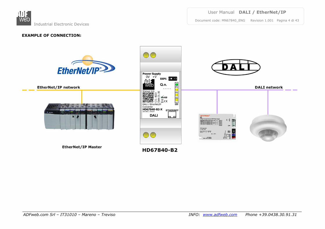
EXAMPLE OF CONNECTION:
Industrial Electronic Devices
ADFweb.com Srl – IT31010 – Mareno – Treviso INFO: www.adfweb.com Phone +39.0438.30.91.31
User Manual DALI / EtherNet/IP
Document code: MN67840_ENG Revision 1.001 Pagina 5 di 43
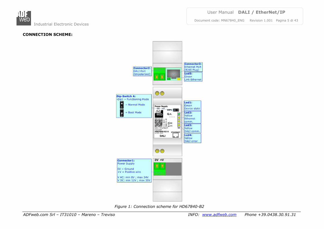
CONNECTION SCHEME:
Figure 1: Connection scheme for HD67840-B2
Industrial Electronic Devices
ADFweb.com Srl – IT31010 – Mareno – Treviso INFO: www.adfweb.com Phone +39.0438.30.91.31
User Manual DALI / EtherNet/IP
Document code: MN67840_ENG Revision 1.001 Pagina 6 di 43
CHARACTERISTICS:
The HD67840 is a DALI / EtherNet/IP - Converter. It has the following characteristics:
Up to 62 devices on DALI bus;
Configurator for DALI network/devices;
Isolation between DALI – Ethernet, Power Supply - Ethernet. Additional isolation Power Supply – DALI for HD67840-B2-N version;
Two-directional information between DALI bus and EtherNet/IP bus;
Mountable on 35mm Rail DIN;
Wide power supply input range: 8…24V AC or 12…35V DC;
Wide temperature range: -40°C / 85°C [-40°F / +185°F].
CONFIGURATION:
You need “DALI Console” software on your PC in order to perform the following:
Configure the DALI network;
Setup the DALI devices (groups, scenes, IDs, …);
Test DALI communication.
You need Compositor SW67840 software on your PC in order to perform the following:
Define the parameter of EtherNet/IP line;
Define the parameter of DALI line;
Update the device.
Industrial Electronic Devices
ADFweb.com Srl – IT31010 – Mareno – Treviso INFO: www.adfweb.com Phone +39.0438.30.91.31
User Manual DALI / EtherNet/IP
Document code: MN67840_ENG Revision 1.001 Pagina 7 di 43
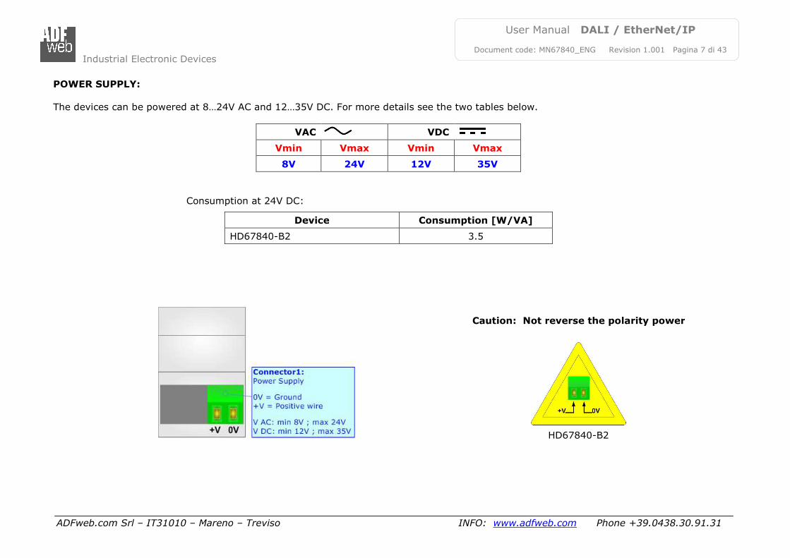
POWER SUPPLY:
The devices can be powered at 8…24V AC and 12…35V DC. For more details see the two tables below.
VAC VDC
Vmin Vmax Vmin Vmax
8V 24V 12V 35V
Consumption at 24V DC:
Device Consumption [W/VA]
HD67840-B2 3.5
HD67840-B2
Caution: Not reverse the polarity power
Industrial Electronic Devices
ADFweb.com Srl – IT31010 – Mareno – Treviso INFO: www.adfweb.com Phone +39.0438.30.91.31
User Manual DALI / EtherNet/IP
Document code: MN67840_ENG Revision 1.001 Pagina 8 di 43
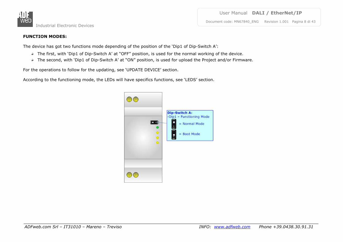
FUNCTION MODES:
The device has got two functions mode depending of the position of the ‘Dip1 of Dip-Switch A’:
The first, with ‘Dip1 of Dip-Switch A’ at “OFF” position, is used for the normal working of the device.
The second, with ‘Dip1 of Dip-Switch A’ at “ON” position, is used for upload the Project and/or Firmware.
For the operations to follow for the updating, see ‘UPDATE DEVICE’ section.
According to the functioning mode, the LEDs will have specifics functions, see ‘LEDS’ section.
Industrial Electronic Devices
ADFweb.com Srl – IT31010 – Mareno – Treviso INFO: www.adfweb.com Phone +39.0438.30.91.31
User Manual DALI / EtherNet/IP
Document code: MN67840_ENG Revision 1.001 Pagina 9 di 43
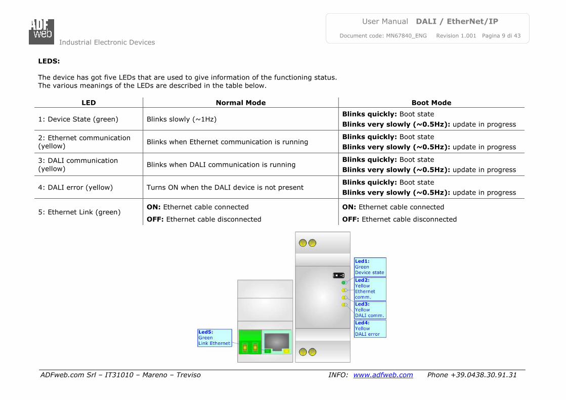
LEDS:
The device has got five LEDs that are used to give information of the functioning status.
The various meanings of the LEDs are described in the table below.
LED Normal Mode Boot Mode
1: Device State (green) Blinks slowly (~1Hz) Blinks quickly: Boot state
Blinks very slowly (~0.5Hz): update in progress
2: Ethernet communication
(yellow) Blinks when Ethernet communication is running
Blinks quickly: Boot state
Blinks very slowly (~0.5Hz): update in progress
3: DALI communication
(yellow) Blinks when DALI communication is running
Blinks quickly: Boot state
Blinks very slowly (~0.5Hz): update in progress
4: DALI error (yellow) Turns ON when the DALI device is not present Blinks quickly: Boot state
Blinks very slowly (~0.5Hz): update in progress
5: Ethernet Link (green) ON: Ethernet cable connected
OFF: Ethernet cable disconnected
ON: Ethernet cable connected
OFF: Ethernet cable disconnected
Industrial Electronic Devices
ADFweb.com Srl – IT31010 – Mareno – Treviso INFO: www.adfweb.com Phone +39.0438.30.91.31
User Manual DALI / EtherNet/IP
Document code: MN67840_ENG Revision 1.001 Pagina 10 di 43
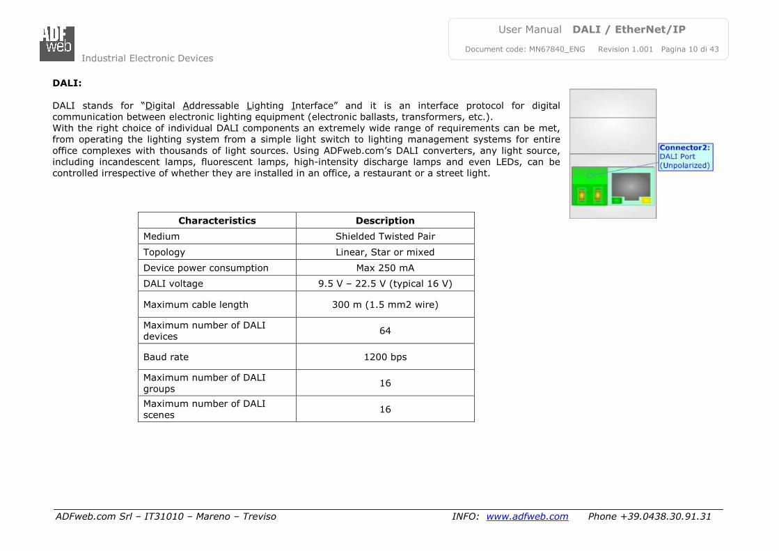
DALI:
DALI stands for “Digital Addressable Lighting Interface” and it is an interface protocol for digital
communication between electronic lighting equipment (electronic ballasts, transformers, etc.).
With the right choice of individual DALI components an extremely wide range of requirements can be met,
from operating the lighting system from a simple light switch to lighting management systems for entire
office complexes with thousands of light sources. Using ADFweb.com’s DALI converters, any light source,
including incandescent lamps, fluorescent lamps, high-intensity discharge lamps and even LEDs, can be
controlled irrespective of whether they are installed in an office, a restaurant or a street light.
Characteristics Description
Medium Shielded Twisted Pair
Topology Linear, Star or mixed
Device power consumption Max 250 mA
DALI voltage 9.5 V – 22.5 V (typical 16 V)
Maximum cable length 300 m (1.5 mm2 wire)
Maximum number of DALI
devices 64
Baud rate 1200 bps
Maximum number of DALI
groups 16
Maximum number of DALI
scenes 16
Industrial Electronic Devices
ADFweb.com Srl – IT31010 – Mareno – Treviso INFO: www.adfweb.com Phone +39.0438.30.91.31
User Manual DALI / EtherNet/IP
Document code: MN67840_ENG Revision 1.001 Pagina 11 di 43
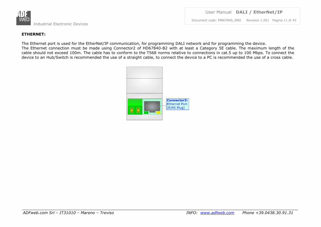
ETHERNET:
The Ethernet port is used for the EtherNet/IP communication, for programming DALI network and for programming the device.
The Ethernet connection must be made using Connector2 of HD67840-B2 with at least a Category 5E cable. The maximum length of the
cable should not exceed 100m. The cable has to conform to the T568 norms relative to connections in cat.5 up to 100 Mbps. To connect the
device to an Hub/Switch is recommended the use of a straight cable, to connect the device to a PC is recommended the use of a cross cable.
Industrial Electronic Devices
ADFweb.com Srl – IT31010 – Mareno – Treviso INFO: www.adfweb.com Phone +39.0438.30.91.31
User Manual DALI / EtherNet/IP
Document code: MN67840_ENG Revision 1.001 Pagina 12 di 43
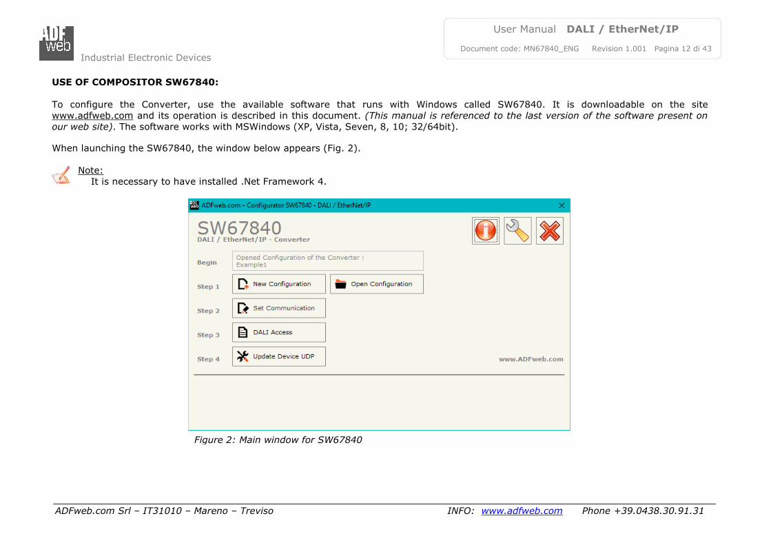
USE OF COMPOSITOR SW67840:
To configure the Converter, use the available software that runs with Windows called SW67840. It is downloadable on the site
www.adfweb.com and its operation is described in this document. (This manual is referenced to the last version of the software present on
our web site). The software works with MSWindows (XP, Vista, Seven, 8, 10; 32/64bit). When launching the SW67840, the window below appears (Fig. 2).
Note:
It is necessary to have installed .Net Framework 4.
Figure 2: Main window for SW67840
Industrial Electronic Devices
ADFweb.com Srl – IT31010 – Mareno – Treviso INFO: www.adfweb.com Phone +39.0438.30.91.31
User Manual DALI / EtherNet/IP
Document code: MN67840_ENG Revision 1.001 Pagina 13 di 43
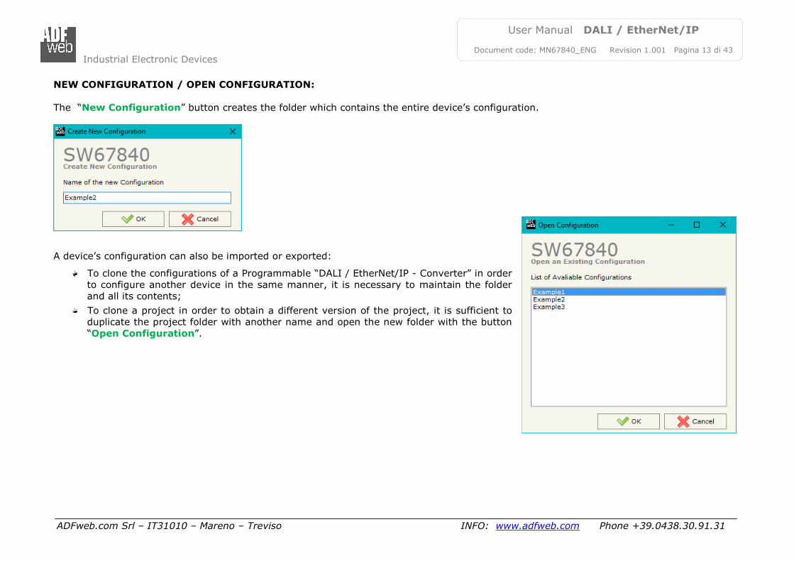
NEW CONFIGURATION / OPEN CONFIGURATION:
The “New Configuration” button creates the folder which contains the entire device’s configuration.
A device’s configuration can also be imported or exported:
To clone the configurations of a Programmable “DALI / EtherNet/IP - Converter” in order
to configure another device in the same manner, it is necessary to maintain the folder
and all its contents;
To clone a project in order to obtain a different version of the project, it is sufficient to
duplicate the project folder with another name and open the new folder with the button
“Open Configuration”.
Industrial Electronic Devices
ADFweb.com Srl – IT31010 – Mareno – Treviso INFO: www.adfweb.com Phone +39.0438.30.91.31
User Manual DALI / EtherNet/IP
Document code: MN67840_ENG Revision 1.001 Pagina 14 di 43
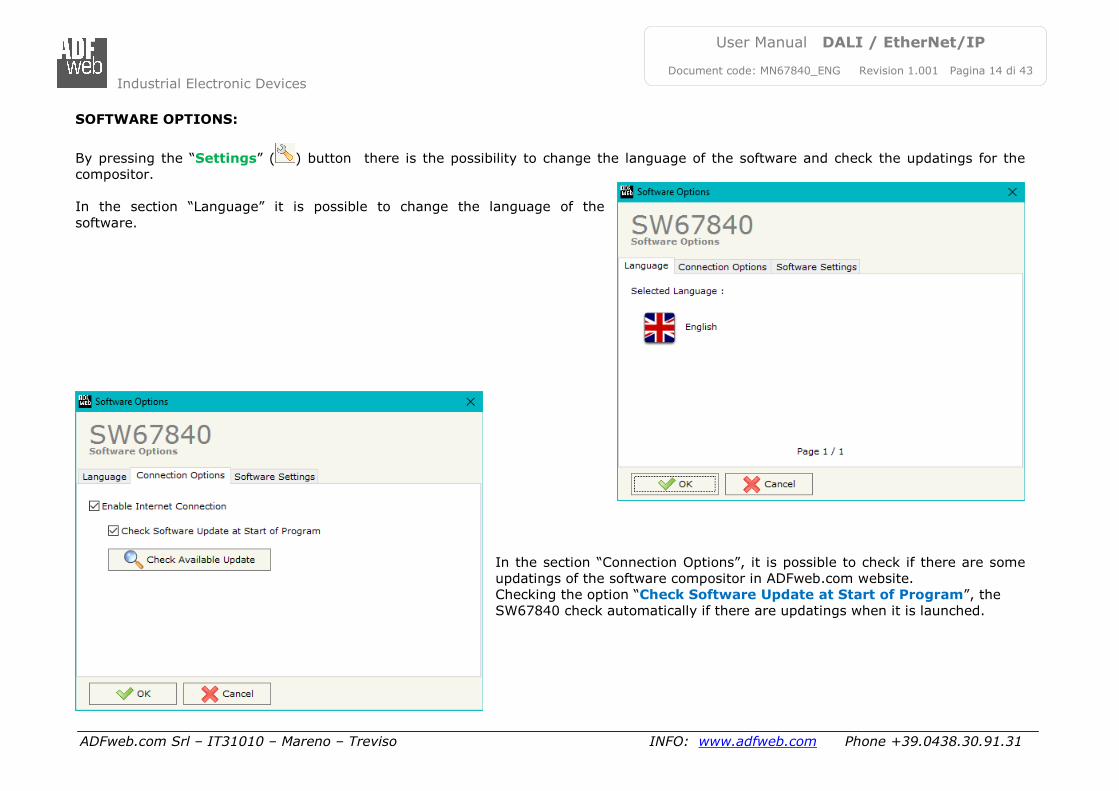
SOFTWARE OPTIONS:
By pressing the “Settings” ( ) button there is the possibility to change the language of the software and check the updatings for the
compositor.
In the section “Language” it is possible to change the language of the
software.
In the section “Connection Options”, it is possible to check if there are some
updatings of the software compositor in ADFweb.com website.
Checking the option “Check Software Update at Start of Program”, the
SW67840 check automatically if there are updatings when it is launched.
Industrial Electronic Devices
ADFweb.com Srl – IT31010 – Mareno – Treviso INFO: www.adfweb.com Phone +39.0438.30.91.31
User Manual DALI / EtherNet/IP
Document code: MN67840_ENG Revision 1.001 Pagina 15 di 43
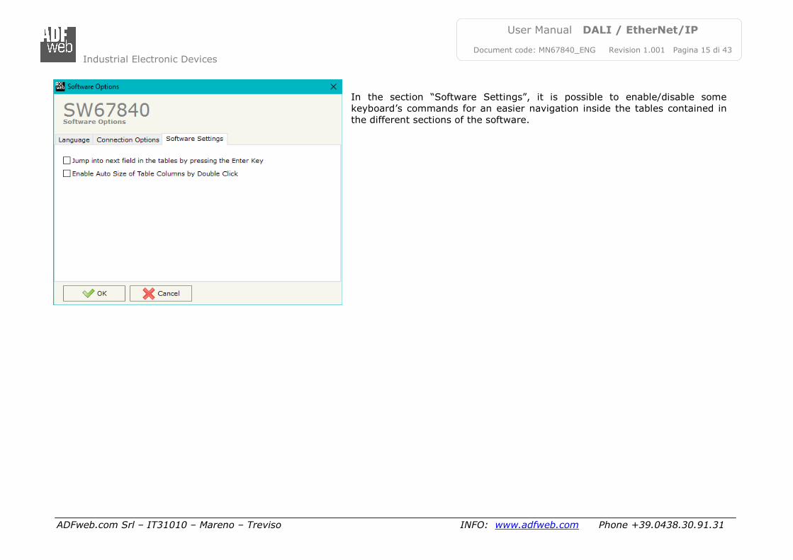
In the section “Software Settings”, it is possible to enable/disable some
keyboard’s commands for an easier navigation inside the tables contained in
the different sections of the software.
Industrial Electronic Devices
ADFweb.com Srl – IT31010 – Mareno – Treviso INFO: www.adfweb.com Phone +39.0438.30.91.31
User Manual DALI / EtherNet/IP
Document code: MN67840_ENG Revision 1.001 Pagina 16 di 43
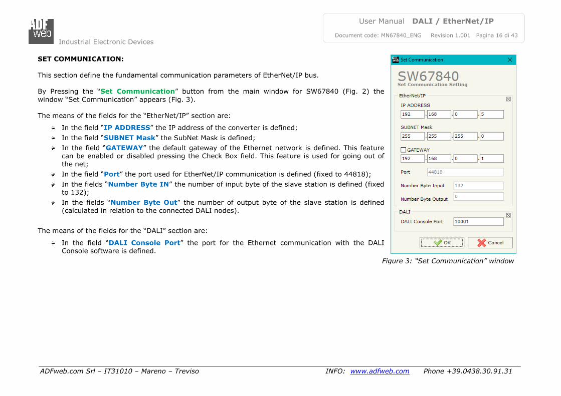
SET COMMUNICATION:
This section define the fundamental communication parameters of EtherNet/IP bus.
By Pressing the “Set Communication” button from the main window for SW67840 (Fig. 2) the
window “Set Communication” appears (Fig. 3).
The means of the fields for the “EtherNet/IP” section are:
In the field “IP ADDRESS” the IP address of the converter is defined;
In the field “SUBNET Mask” the SubNet Mask is defined;
In the field “GATEWAY” the default gateway of the Ethernet network is defined. This feature
can be enabled or disabled pressing the Check Box field. This feature is used for going out of
the net;
In the field “Port” the port used for EtherNet/IP communication is defined (fixed to 44818);
In the fields “Number Byte IN” the number of input byte of the slave station is defined (fixed
to 132);
In the fields “Number Byte Out” the number of output byte of the slave station is defined
(calculated in relation to the connected DALI nodes).
The means of the fields for the “DALI” section are:
In the field “DALI Console Port” the port for the Ethernet communication with the DALI
Console software is defined.
Figure 3: “Set Communication” window
Industrial Electronic Devices
ADFweb.com Srl – IT31010 – Mareno – Treviso INFO: www.adfweb.com Phone +39.0438.30.91.31
User Manual DALI / EtherNet/IP
Document code: MN67840_ENG Revision 1.001 Pagina 17 di 43
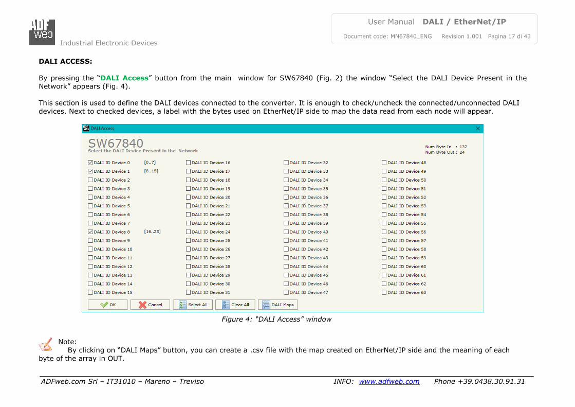
DALI ACCESS:
By pressing the “DALI Access” button from the main window for SW67840 (Fig. 2) the window “Select the DALI Device Present in the
Network” appears (Fig. 4).
This section is used to define the DALI devices connected to the converter. It is enough to check/uncheck the connected/unconnected DALI
devices. Next to checked devices, a label with the bytes used on EtherNet/IP side to map the data read from each node will appear.
Note:
By clicking on “DALI Maps” button, you can create a .csv file with the map created on EtherNet/IP side and the meaning of each
byte of the array in OUT.
Figure 4: “DALI Access” window
Industrial Electronic Devices
ADFweb.com Srl – IT31010 – Mareno – Treviso INFO: www.adfweb.com Phone +39.0438.30.91.31
User Manual DALI / EtherNet/IP
Document code: MN67840_ENG Revision 1.001 Pagina 18 di 43
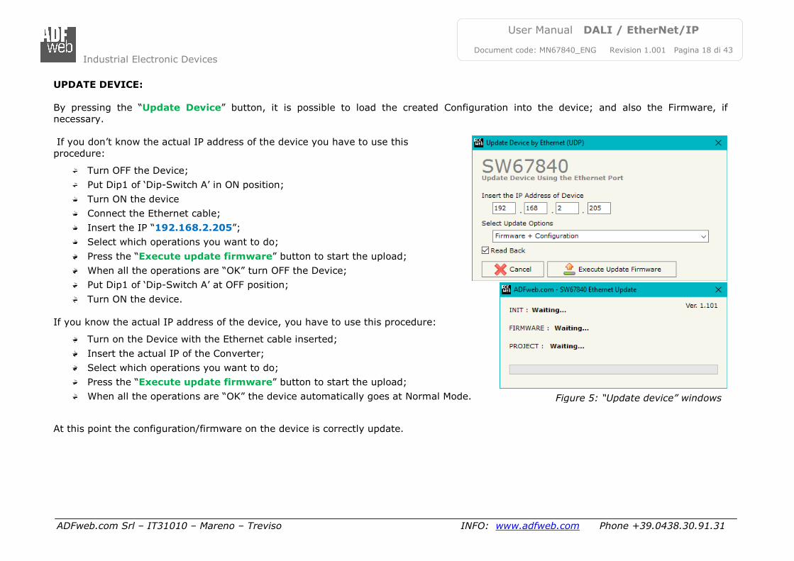
UPDATE DEVICE:
By pressing the “Update Device” button, it is possible to load the created Configuration into the device; and also the Firmware, if
necessary.
If you don’t know the actual IP address of the device you have to use this
procedure:
Turn OFF the Device;
Put Dip1 of ‘Dip-Switch A’ in ON position;
Turn ON the device
Connect the Ethernet cable;
Insert the IP “192.168.2.205”;
Select which operations you want to do;
Press the “Execute update firmware” button to start the upload;
When all the operations are “OK” turn OFF the Device;
Put Dip1 of ‘Dip-Switch A’ at OFF position;
Turn ON the device.
If you know the actual IP address of the device, you have to use this procedure:
Turn on the Device with the Ethernet cable inserted;
Insert the actual IP of the Converter;
Select which operations you want to do;
Press the “Execute update firmware” button to start the upload;
When all the operations are “OK” the device automatically goes at Normal Mode.
At this point the configuration/firmware on the device is correctly update.
Figure 5: “Update device” windows
Industrial Electronic Devices
ADFweb.com Srl – IT31010 – Mareno – Treviso INFO: www.adfweb.com Phone +39.0438.30.91.31
User Manual DALI / EtherNet/IP
Document code: MN67840_ENG Revision 1.001 Pagina 19 di 43
Note:
When you install a new version of the software, if it is the first time it is better you do the update of the Firmware in the HD67840
device.
Note:
When you receive the device, for the first time, you also have to update the Firmware in the HD67840 device.
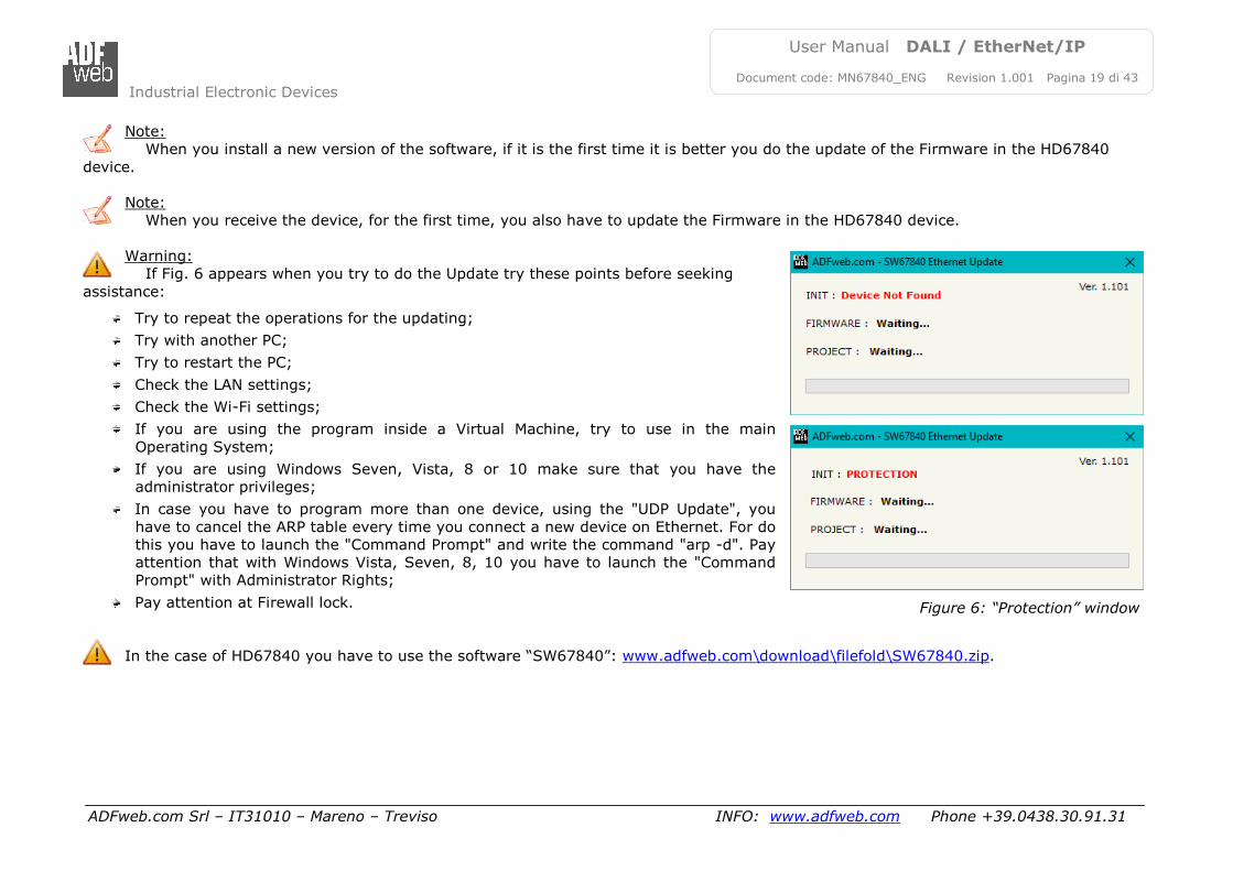
Warning:
If Fig. 6 appears when you try to do the Update try these points before seeking
assistance:
Try to repeat the operations for the updating;
Try with another PC;
Try to restart the PC;
Check the LAN settings;
Check the Wi-Fi settings;
If you are using the program inside a Virtual Machine, try to use in the main
Operating System;
If you are using Windows Seven, Vista, 8 or 10 make sure that you have the
administrator privileges;
In case you have to program more than one device, using the "UDP Update", you
have to cancel the ARP table every time you connect a new device on Ethernet. For do
this you have to launch the "Command Prompt" and write the command "arp -d". Pay
attention that with Windows Vista, Seven, 8, 10 you have to launch the "Command
Prompt" with Administrator Rights;
Pay attention at Firewall lock.
In the case of HD67840 you have to use the software “SW67840”: www.adfweb.com\download\filefold\SW67840.zip.
Figure 6: “Protection” window
Industrial Electronic Devices
ADFweb.com Srl – IT31010 – Mareno – Treviso INFO: www.adfweb.com Phone +39.0438.30.91.31
User Manual DALI / EtherNet/IP
Document code: MN67840_ENG Revision 1.001 Pagina 20 di 43
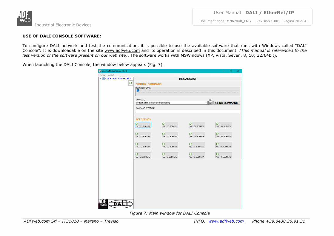
USE OF DALI CONSOLE SOFTWARE:
To configure DALI network and test the communication, it is possible to use the available software that runs with Windows called “DALI
Console”. It is downloadable on the site www.adfweb.com and its operation is described in this document. (This manual is referenced to the
last version of the software present on our web site). The software works with MSWindows (XP, Vista, Seven, 8, 10; 32/64bit). When launching the DALI Console, the window below appears (Fig. 7).
Figure 7: Main window for DALI Console
Industrial Electronic Devices
ADFweb.com Srl – IT31010 – Mareno – Treviso INFO: www.adfweb.com Phone +39.0438.30.91.31
User Manual DALI / EtherNet/IP
Document code: MN67840_ENG Revision 1.001 Pagina 21 di 43
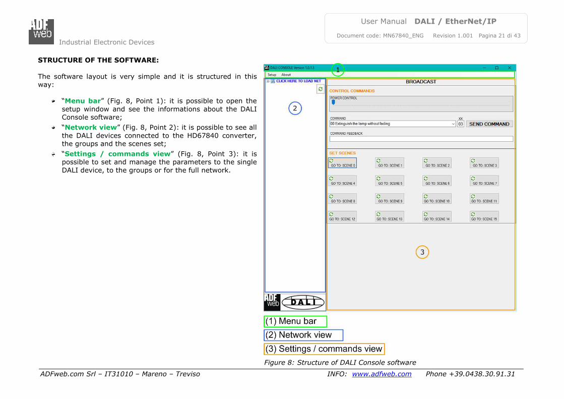
STRUCTURE OF THE SOFTWARE:
The software layout is very simple and it is structured in this
way:
“Menu bar” (Fig. 8, Point 1): it is possible to open the
setup window and see the informations about the DALI
Console software;
“Network view” (Fig. 8, Point 2): it is possible to see all
the DALI devices connected to the HD67840 converter,
the groups and the scenes set;
“Settings / commands view” (Fig. 8, Point 3): it is
possible to set and manage the parameters to the single
DALI device, to the groups or for the full network.
Figure 8: Structure of DALI Console software
Industrial Electronic Devices
ADFweb.com Srl – IT31010 – Mareno – Treviso INFO: www.adfweb.com Phone +39.0438.30.91.31
User Manual DALI / EtherNet/IP
Document code: MN67840_ENG Revision 1.001 Pagina 22 di 43
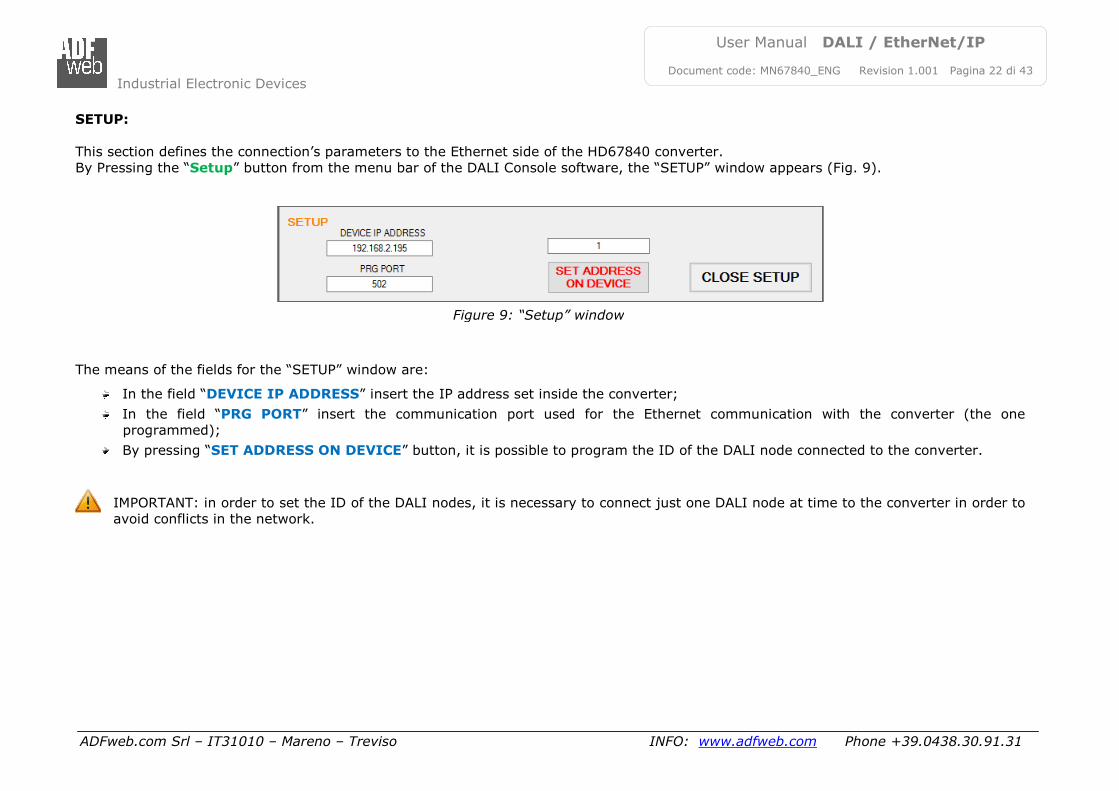
SETUP:
This section defines the connection’s parameters to the Ethernet side of the HD67840 converter.
By Pressing the “Setup” button from the menu bar of the DALI Console software, the “SETUP” window appears (Fig. 9).
The means of the fields for the “SETUP” window are:
In the field “DEVICE IP ADDRESS” insert the IP address set inside the converter;
In the field “PRG PORT” insert the communication port used for the Ethernet communication with the converter (the one
programmed);
By pressing “SET ADDRESS ON DEVICE” button, it is possible to program the ID of the DALI node connected to the converter.
IMPORTANT: in order to set the ID of the DALI nodes, it is necessary to connect just one DALI node at time to the converter in order to
avoid conflicts in the network.
Figure 9: “Setup” window
Industrial Electronic Devices
ADFweb.com Srl – IT31010 – Mareno – Treviso INFO: www.adfweb.com Phone +39.0438.30.91.31
User Manual DALI / EtherNet/IP
Document code: MN67840_ENG Revision 1.001 Pagina 23 di 43
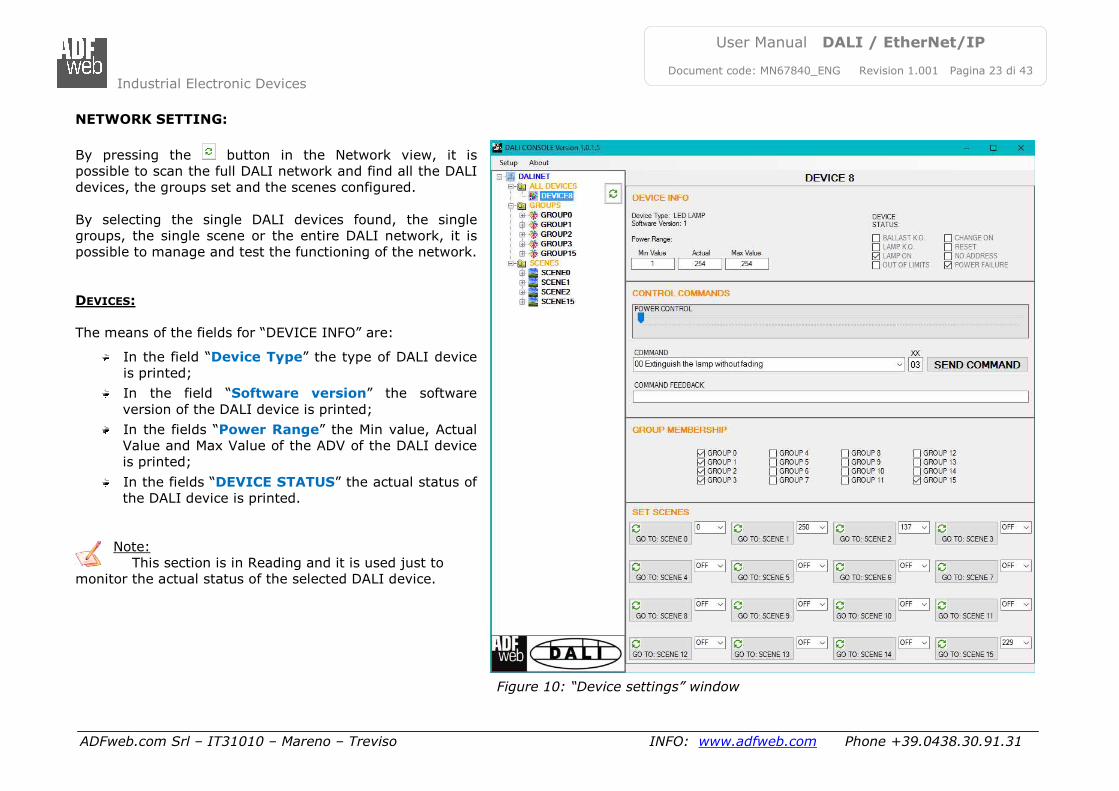
NETWORK SETTING:
By pressing the button in the Network view, it is
possible to scan the full DALI network and find all the DALI
devices, the groups set and the scenes configured.
By selecting the single DALI devices found, the single
groups, the single scene or the entire DALI network, it is
possible to manage and test the functioning of the network.
DEVICES:
The means of the fields for “DEVICE INFO” are:
In the field “Device Type” the type of DALI device
is printed;
In the field “Software version” the software
version of the DALI device is printed;
In the fields “Power Range” the Min value, Actual
Value and Max Value of the ADV of the DALI device
is printed;
In the fields “DEVICE STATUS” the actual status of
the DALI device is printed.
Note:
This section is in Reading and it is used just to
monitor the actual status of the selected DALI device.
Figure 10: “Device settings” window
Industrial Electronic Devices
ADFweb.com Srl – IT31010 – Mareno – Treviso INFO: www.adfweb.com Phone +39.0438.30.91.31
User Manual DALI / EtherNet/IP
Document code: MN67840_ENG Revision 1.001 Pagina 24 di 43
The means of the fields for the “CONTROL COMMANDS” section are:
In the “POWER CONTROL” bar it is possible to change the actual ADV of the selected DALI device;
In the field “COMMAND” it is possible to select a DALI command to send to the selected DALI device. For set commands, it is
possible to insert the value to set in the field “xx”. As soon as the command to send is selected, the command is sent: in order to
send the same command more times, it is possible to press the “SEND COMMAND” button;
In the field “COMMAND FEEDBACK” the response from the DALI device is printed.
Note:
This section is used to test the functioning of the DALI device in the network and to set specific parameters if ned (like new
Minimum or Maximum ADV value).
In the “GROUP MEMBERSHIP” section it is possible to see the Groups which the selected DALI device is in. The checked checkboxes mean
that the device is in the correspondent groups, the unchecked checkboxes mean that the device is not included in the correspondent groups.
It is possible to change the group settings for the selected DALI device by checking/unchecking the correspondent checkboxes.
In the “SET SCENES” section it is possible to see the programmed scenes of the selected DALI device, program new ones and activate them:
By pressing the buttons “GO TO: SCENE X” it is possible to activate the correspondent scene inside the selected DALI device; the
programmed ADV for the selected scene is defined in the drop-down list on the right;
By selecting a value into the drop-down lists next to the “GO TO: SCENE x” buttons, it is possible to set the ADV associated to the
correspondent scene. It is possible to select:
o Value between 0 and 255: the scene will have the defined value of ADV;
o ACT: the scene will take the programmed ADV value into the “POWER CONTROL” bar;
o OFF: the scene is disabled.
Industrial Electronic Devices
ADFweb.com Srl – IT31010 – Mareno – Treviso INFO: www.adfweb.com Phone +39.0438.30.91.31
User Manual DALI / EtherNet/IP
Document code: MN67840_ENG Revision 1.001 Pagina 25 di 43
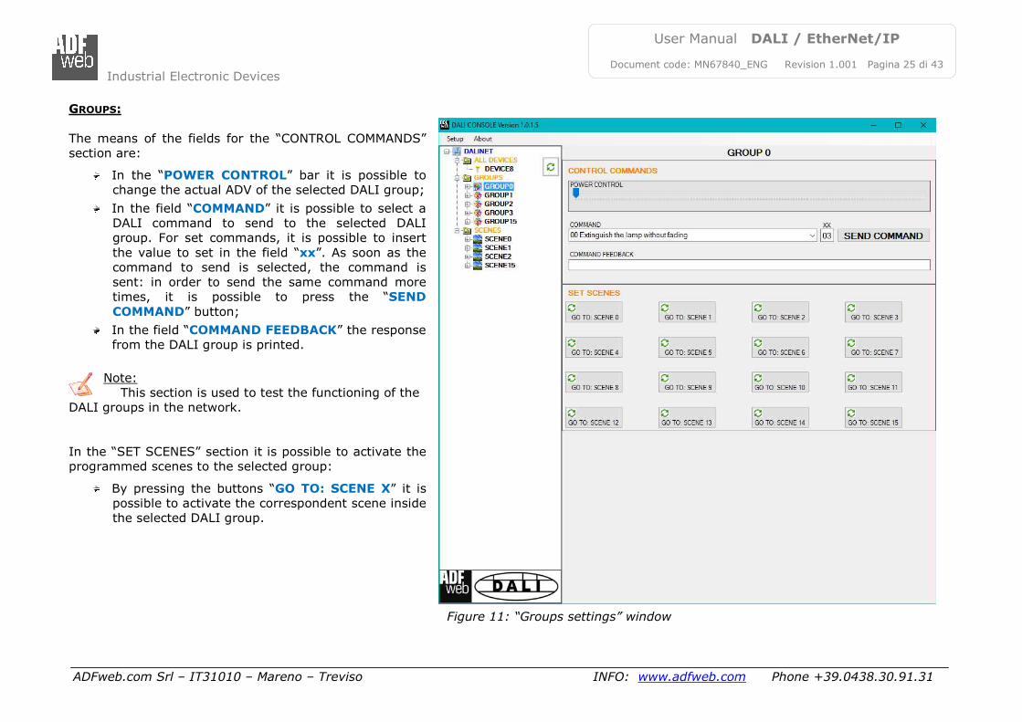
GROUPS:
The means of the fields for the “CONTROL COMMANDS”
section are:
In the “POWER CONTROL” bar it is possible to
change the actual ADV of the selected DALI group;
In the field “COMMAND” it is possible to select a
DALI command to send to the selected DALI
group. For set commands, it is possible to insert
the value to set in the field “xx”. As soon as the
command to send is selected, the command is
sent: in order to send the same command more
times, it is possible to press the “SEND
COMMAND” button;
In the field “COMMAND FEEDBACK” the response
from the DALI group is printed.
Note:
This section is used to test the functioning of the
DALI groups in the network.
In the “SET SCENES” section it is possible to activate the
programmed scenes to the selected group:
By pressing the buttons “GO TO: SCENE X” it is
possible to activate the correspondent scene inside
the selected DALI group.
Figure 11: “Groups settings” window
Industrial Electronic Devices
ADFweb.com Srl – IT31010 – Mareno – Treviso INFO: www.adfweb.com Phone +39.0438.30.91.31
User Manual DALI / EtherNet/IP
Document code: MN67840_ENG Revision 1.001 Pagina 26 di 43
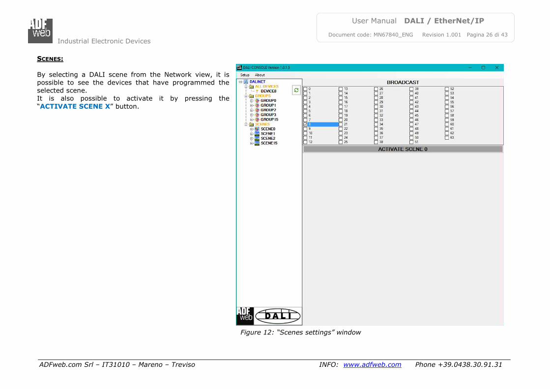
SCENES:
By selecting a DALI scene from the Network view, it is
possible to see the devices that have programmed the
selected scene.
It is also possible to activate it by pressing the
“ACTIVATE SCENE X” button.
Figure 12: “Scenes settings” window
Industrial Electronic Devices
ADFweb.com Srl – IT31010 – Mareno – Treviso INFO: www.adfweb.com Phone +39.0438.30.91.31
User Manual DALI / EtherNet/IP
Document code: MN67840_ENG Revision 1.001 Pagina 27 di 43
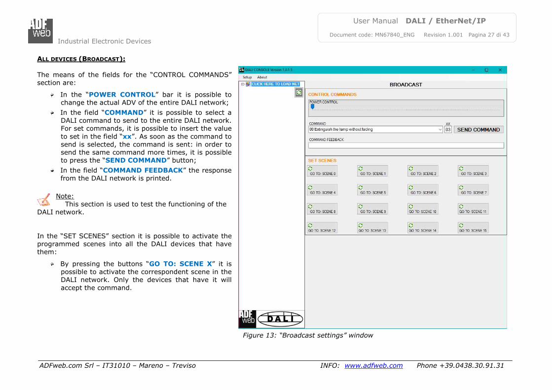
ALL DEVICES (BROADCAST):
The means of the fields for the “CONTROL COMMANDS”
section are:
In the “POWER CONTROL” bar it is possible to
change the actual ADV of the entire DALI network;
In the field “COMMAND” it is possible to select a
DALI command to send to the entire DALI network.
For set commands, it is possible to insert the value
to set in the field “xx”. As soon as the command to
send is selected, the command is sent: in order to
send the same command more times, it is possible
to press the “SEND COMMAND” button;
In the field “COMMAND FEEDBACK” the response
from the DALI network is printed.
Note:
This section is used to test the functioning of the
DALI network.
In the “SET SCENES” section it is possible to activate the
programmed scenes into all the DALI devices that have
them:
By pressing the buttons “GO TO: SCENE X” it is
possible to activate the correspondent scene in the
DALI network. Only the devices that have it will
accept the command.
Figure 13: “Broadcast settings” window
Industrial Electronic Devices
ADFweb.com Srl – IT31010 – Mareno – Treviso INFO: www.adfweb.com Phone +39.0438.30.91.31
User Manual DALI / EtherNet/IP
Document code: MN67840_ENG Revision 1.001 Pagina 28 di 43
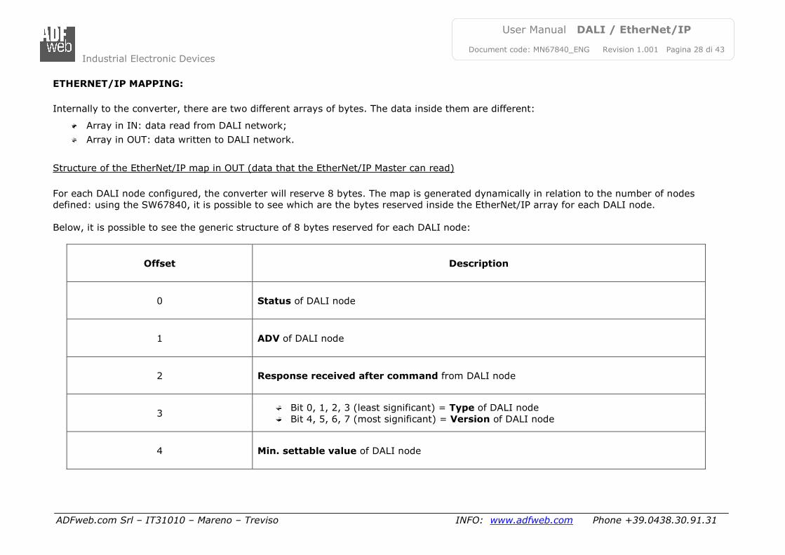
ETHERNET/IP MAPPING:
Internally to the converter, there are two different arrays of bytes. The data inside them are different:
Array in IN: data read from DALI network;
Array in OUT: data written to DALI network.
Structure of the EtherNet/IP map in OUT (data that the EtherNet/IP Master can read)
For each DALI node configured, the converter will reserve 8 bytes. The map is generated dynamically in relation to the number of nodes
defined: using the SW67840, it is possible to see which are the bytes reserved inside the EtherNet/IP array for each DALI node.
Below, it is possible to see the generic structure of 8 bytes reserved for each DALI node:
Offset Description
0 Status of DALI node
1 ADV of DALI node
2 Response received after command from DALI node
3 Bit 0, 1, 2, 3 (least significant) = Type of DALI node
Bit 4, 5, 6, 7 (most significant) = Version of DALI node
4 Min. settable value of DALI node
Industrial Electronic Devices
ADFweb.com Srl – IT31010 – Mareno – Treviso INFO: www.adfweb.com Phone +39.0438.30.91.31
User Manual DALI / EtherNet/IP
Document code: MN67840_ENG Revision 1.001 Pagina 29 di 43
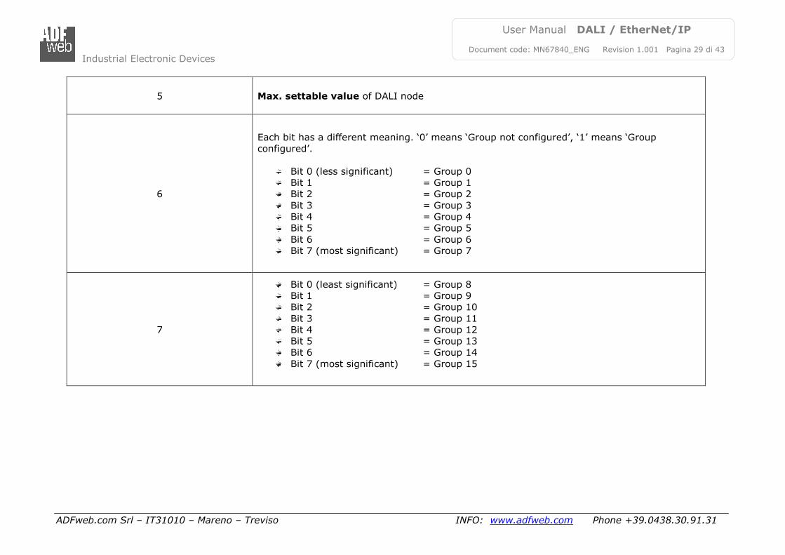
5 Max. settable value of DALI node
6
Each bit has a different meaning. ‘0’ means ‘Group not configured’, ‘1’ means ‘Group
configured’.
Bit 0 (less significant) = Group 0
Bit 1 = Group 1
Bit 2 = Group 2
Bit 3 = Group 3
Bit 4 = Group 4
Bit 5 = Group 5
Bit 6 = Group 6
Bit 7 (most significant) = Group 7
7
Bit 0 (least significant) = Group 8
Bit 1 = Group 9
Bit 2 = Group 10
Bit 3 = Group 11
Bit 4 = Group 12
Bit 5 = Group 13
Bit 6 = Group 14
Bit 7 (most significant) = Group 15
Industrial Electronic Devices
ADFweb.com Srl – IT31010 – Mareno – Treviso INFO: www.adfweb.com Phone +39.0438.30.91.31
User Manual DALI / EtherNet/IP
Document code: MN67840_ENG Revision 1.001 Pagina 30 di 43
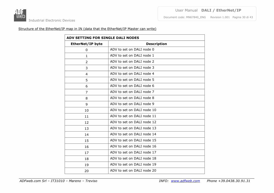
Structure of the EtherNet/IP map in IN (data that the EtherNet/IP Master can write)
ADV SETTING FOR SINGLE DALI NODES
EtherNet/IP byte Description
0 ADV to set on DALI node 0
1 ADV to set on DALI node 1
2 ADV to set on DALI node 2
3 ADV to set on DALI node 3
4 ADV to set on DALI node 4
5 ADV to set on DALI node 5
6 ADV to set on DALI node 6
7 ADV to set on DALI node 7
8 ADV to set on DALI node 8
9 ADV to set on DALI node 9
10 ADV to set on DALI node 10
11 ADV to set on DALI node 11
12 ADV to set on DALI node 12
13 ADV to set on DALI node 13
14 ADV to set on DALI node 14
15 ADV to set on DALI node 15
16 ADV to set on DALI node 16
17 ADV to set on DALI node 17
18 ADV to set on DALI node 18
19 ADV to set on DALI node 19
20 ADV to set on DALI node 20
Industrial Electronic Devices
ADFweb.com Srl – IT31010 – Mareno – Treviso INFO: www.adfweb.com Phone +39.0438.30.91.31
User Manual DALI / EtherNet/IP
Document code: MN67840_ENG Revision 1.001 Pagina 31 di 43
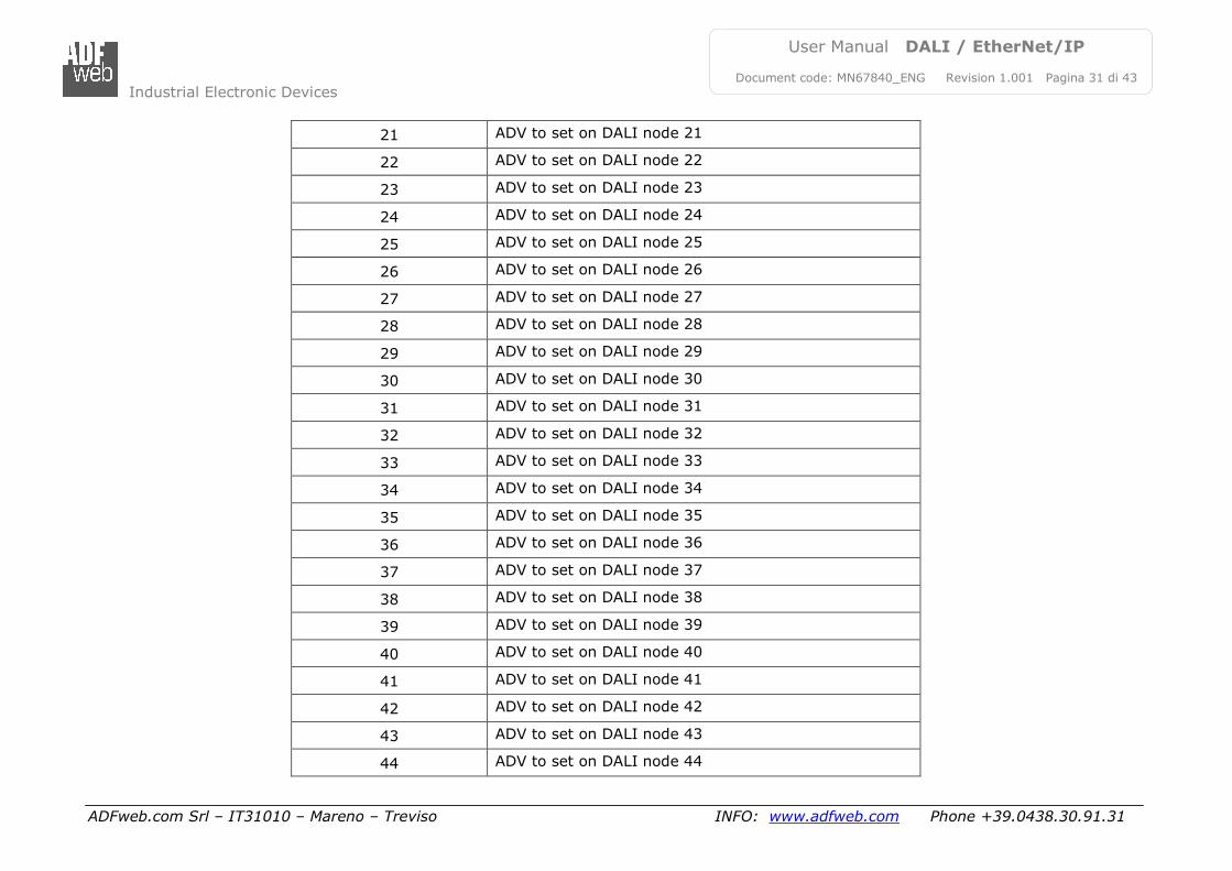
21 ADV to set on DALI node 21
22 ADV to set on DALI node 22
23 ADV to set on DALI node 23
24 ADV to set on DALI node 24
25 ADV to set on DALI node 25
26 ADV to set on DALI node 26
27 ADV to set on DALI node 27
28 ADV to set on DALI node 28
29 ADV to set on DALI node 29
30 ADV to set on DALI node 30
31 ADV to set on DALI node 31
32 ADV to set on DALI node 32
33 ADV to set on DALI node 33
34 ADV to set on DALI node 34
35 ADV to set on DALI node 35
36 ADV to set on DALI node 36
37 ADV to set on DALI node 37
38 ADV to set on DALI node 38
39 ADV to set on DALI node 39
40 ADV to set on DALI node 40
41 ADV to set on DALI node 41
42 ADV to set on DALI node 42
43 ADV to set on DALI node 43
44 ADV to set on DALI node 44
Industrial Electronic Devices
ADFweb.com Srl – IT31010 – Mareno – Treviso INFO: www.adfweb.com Phone +39.0438.30.91.31
User Manual DALI / EtherNet/IP
Document code: MN67840_ENG Revision 1.001 Pagina 32 di 43
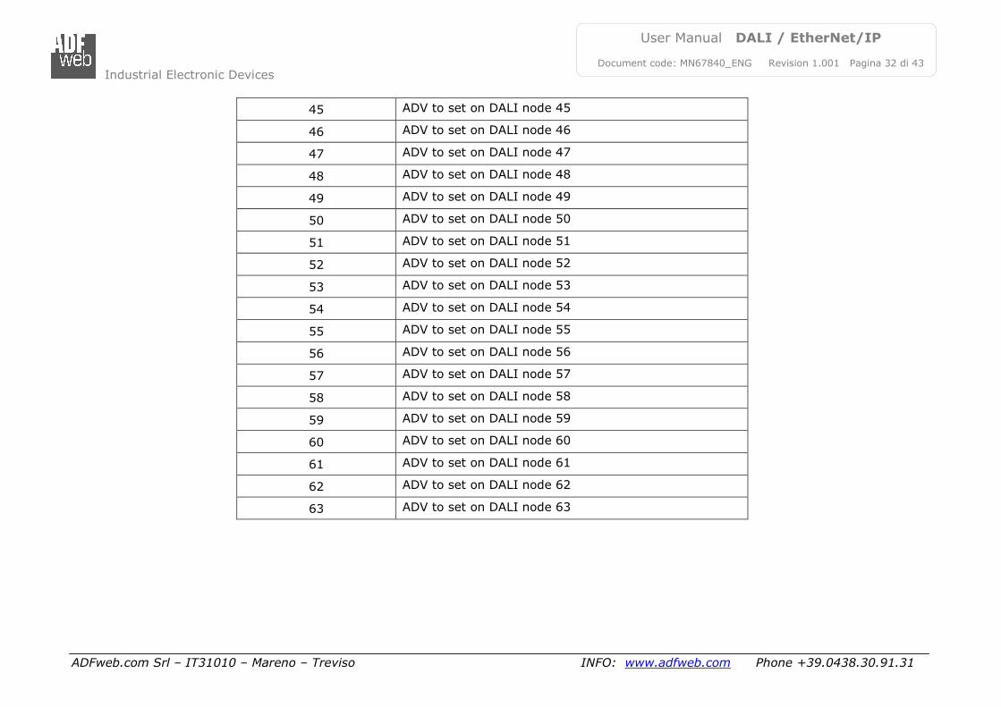
45 ADV to set on DALI node 45
46 ADV to set on DALI node 46
47 ADV to set on DALI node 47
48 ADV to set on DALI node 48
49 ADV to set on DALI node 49
50 ADV to set on DALI node 50
51 ADV to set on DALI node 51
52 ADV to set on DALI node 52
53 ADV to set on DALI node 53
54 ADV to set on DALI node 54
55 ADV to set on DALI node 55
56 ADV to set on DALI node 56
57 ADV to set on DALI node 57
58 ADV to set on DALI node 58
59 ADV to set on DALI node 59
60 ADV to set on DALI node 60
61 ADV to set on DALI node 61
62 ADV to set on DALI node 62
63 ADV to set on DALI node 63
Industrial Electronic Devices
ADFweb.com Srl – IT31010 – Mareno – Treviso INFO: www.adfweb.com Phone +39.0438.30.91.31
User Manual DALI / EtherNet/IP
Document code: MN67840_ENG Revision 1.001 Pagina 33 di 43
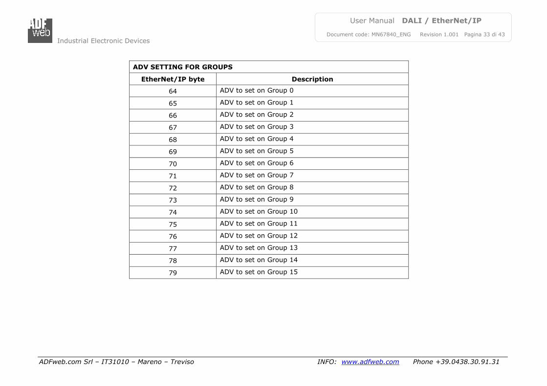
ADV SETTING FOR GROUPS
EtherNet/IP byte Description
64 ADV to set on Group 0
65 ADV to set on Group 1
66 ADV to set on Group 2
67 ADV to set on Group 3
68 ADV to set on Group 4
69 ADV to set on Group 5
70 ADV to set on Group 6
71 ADV to set on Group 7
72 ADV to set on Group 8
73 ADV to set on Group 9
74 ADV to set on Group 10
75 ADV to set on Group 11
76 ADV to set on Group 12
77 ADV to set on Group 13
78 ADV to set on Group 14
79 ADV to set on Group 15
Industrial Electronic Devices
ADFweb.com Srl – IT31010 – Mareno – Treviso INFO: www.adfweb.com Phone +39.0438.30.91.31
User Manual DALI / EtherNet/IP
Document code: MN67840_ENG Revision 1.001 Pagina 34 di 43
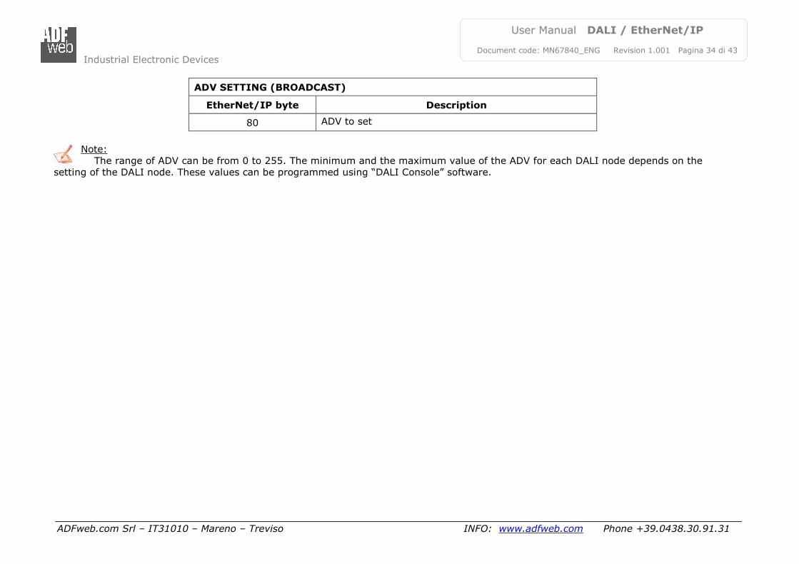
ADV SETTING (BROADCAST)
EtherNet/IP byte Description
80 ADV to set
Note:
The range of ADV can be from 0 to 255. The minimum and the maximum value of the ADV for each DALI node depends on the
setting of the DALI node. These values can be programmed using “DALI Console” software.
Industrial Electronic Devices
ADFweb.com Srl – IT31010 – Mareno – Treviso INFO: www.adfweb.com Phone +39.0438.30.91.31
User Manual DALI / EtherNet/IP
Document code: MN67840_ENG Revision 1.001 Pagina 35 di 43
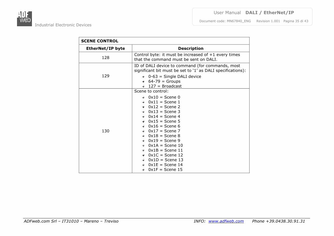
SCENE CONTROL
EtherNet/IP byte Description
128 Control byte: it must be increased of +1 every times
that the command must be sent on DALI.
129
ID of DALI device to command (for commands, most
significant bit must be set to ‘1’ as DALI specifications):
0-63 = Single DALI device
64-79 = Groups
127 = Broadcast
130
Scene to control:
0x10 = Scene 0
0x11 = Scene 1
0x12 = Scene 2
0x13 = Scene 3
0x14 = Scene 4
0x15 = Scene 5
0x16 = Scene 6
0x17 = Scene 7
0x18 = Scene 8
0x19 = Scene 9
0x1A = Scene 10
0x1B = Scene 11
0x1C = Scene 12
0x1D = Scene 13
0x1E = Scene 14
0x1F = Scene 15
Industrial Electronic Devices
ADFweb.com Srl – IT31010 – Mareno – Treviso INFO: www.adfweb.com Phone +39.0438.30.91.31
User Manual DALI / EtherNet/IP
Document code: MN67840_ENG Revision 1.001 Pagina 36 di 43
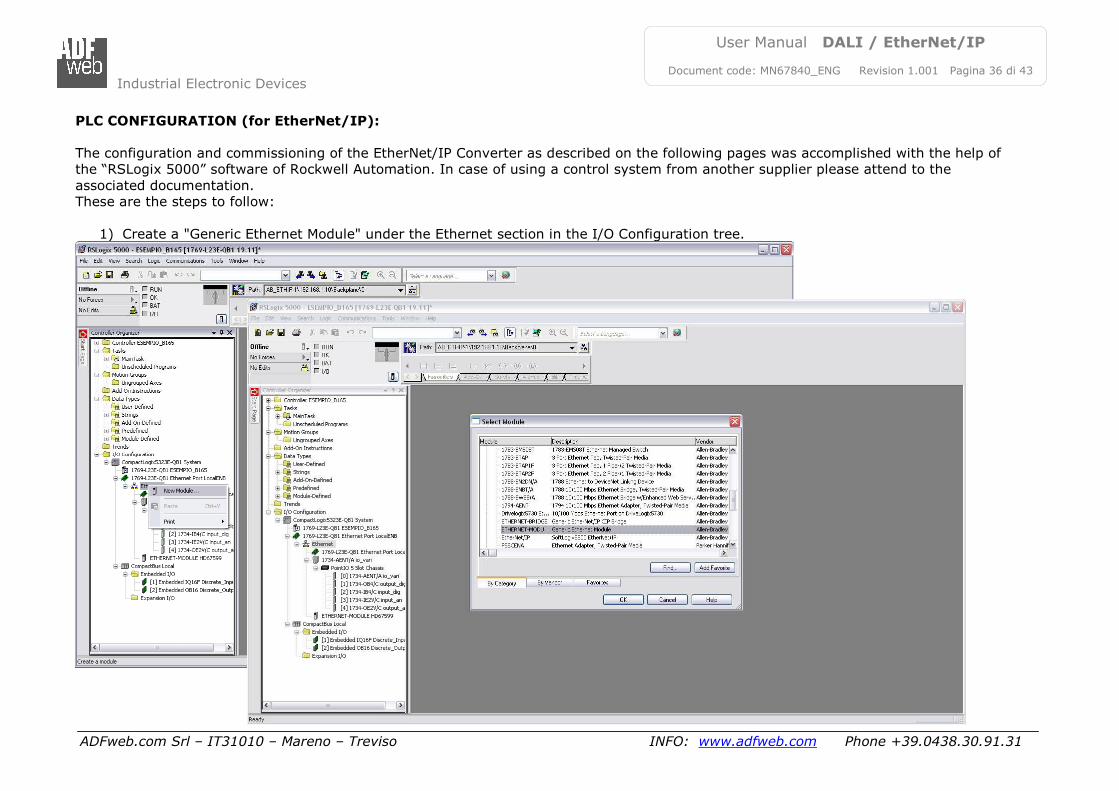
PLC CONFIGURATION (for EtherNet/IP):
The configuration and commissioning of the EtherNet/IP Converter as described on the following pages was accomplished with the help of
the “RSLogix 5000” software of Rockwell Automation. In case of using a control system from another supplier please attend to the
associated documentation.
These are the steps to follow:
1) Create a "Generic Ethernet Module" under the Ethernet section in the I/O Configuration tree.
Industrial Electronic Devices
ADFweb.com Srl – IT31010 – Mareno – Treviso INFO: www.adfweb.com Phone +39.0438.30.91.31
User Manual DALI / EtherNet/IP
Document code: MN67840_ENG Revision 1.001 Pagina 37 di 43
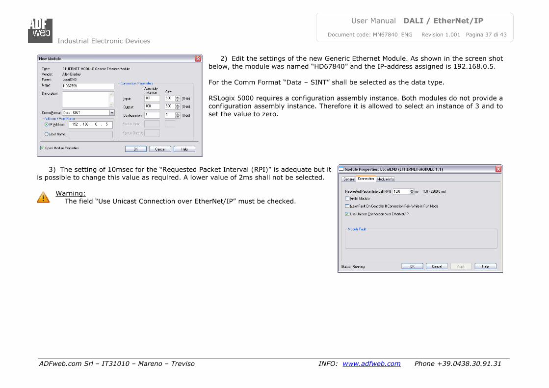
2) Edit the settings of the new Generic Ethernet Module. As shown in the screen shot
below, the module was named “HD67840” and the IP-address assigned is 192.168.0.5.
For the Comm Format “Data – SINT” shall be selected as the data type.
RSLogix 5000 requires a configuration assembly instance. Both modules do not provide a
configuration assembly instance. Therefore it is allowed to select an instance of 3 and to
set the value to zero.
3) The setting of 10msec for the “Requested Packet Interval (RPI)” is adequate but it
is possible to change this value as required. A lower value of 2ms shall not be selected.
Warning:
The field “Use Unicast Connection over EtherNet/IP” must be checked.
Industrial Electronic Devices
ADFweb.com Srl – IT31010 – Mareno – Treviso INFO: www.adfweb.com Phone +39.0438.30.91.31
User Manual DALI / EtherNet/IP
Document code: MN67840_ENG Revision 1.001 Pagina 38 di 43
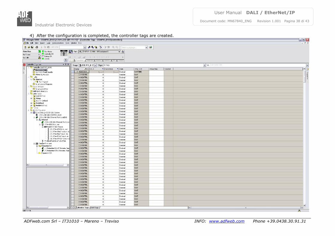
4) After the configuration is completed, the controller tags are created.
Industrial Electronic Devices
ADFweb.com Srl – IT31010 – Mareno – Treviso INFO: www.adfweb.com Phone +39.0438.30.91.31
User Manual DALI / EtherNet/IP
Document code: MN67840_ENG Revision 1.001 Pagina 39 di 43
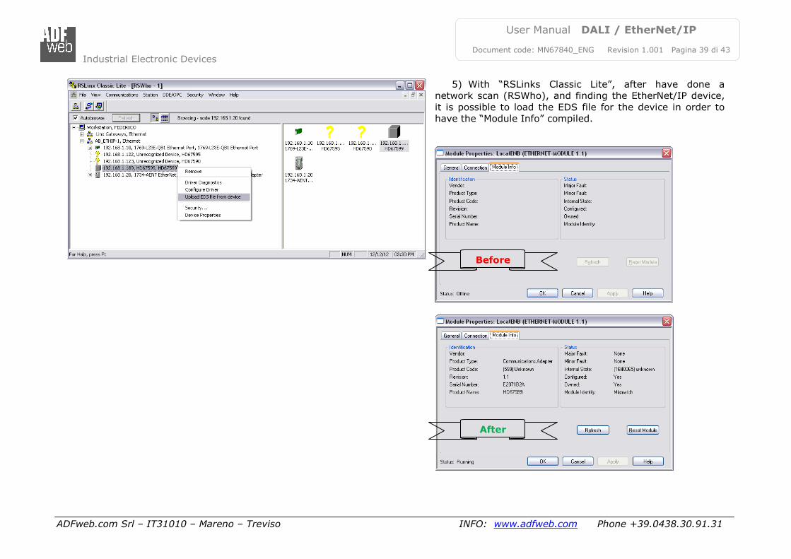
5) With “RSLinks Classic Lite”, after have done a
network scan (RSWho), and finding the EtherNet/IP device,
it is possible to load the EDS file for the device in order to
have the “Module Info” compiled.
Before
After
Industrial Electronic Devices
ADFweb.com Srl – IT31010 – Mareno – Treviso INFO: www.adfweb.com Phone +39.0438.30.91.31
User Manual DALI / EtherNet/IP
Document code: MN67840_ENG Revision 1.001 Pagina 40 di 43
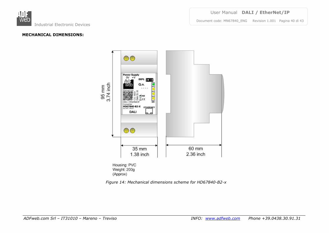
MECHANICAL DIMENSIONS:
Figure 14: Mechanical dimensions scheme for HD67840-B2-x
Industrial Electronic Devices
ADFweb.com Srl – IT31010 – Mareno – Treviso INFO: www.adfweb.com Phone +39.0438.30.91.31
User Manual DALI / EtherNet/IP
Document code: MN67840_ENG Revision 1.001 Pagina 41 di 43
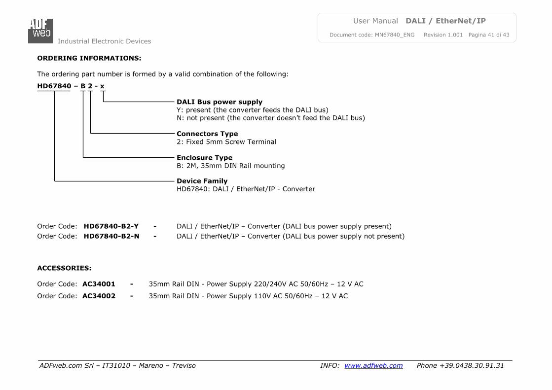
ORDERING INFORMATIONS:
The ordering part number is formed by a valid combination of the following:
HD67840 – B 2 - x
DALI Bus power supply
Y: present (the converter feeds the DALI bus)
N: not present (the converter doesn’t feed the DALI bus)
Connectors Type
2: Fixed 5mm Screw Terminal
Enclosure Type
B: 2M, 35mm DIN Rail mounting
Device Family
HD67840: DALI / EtherNet/IP - Converter Order Code: HD67840-B2-Y - DALI / EtherNet/IP – Converter (DALI bus power supply present)
Order Code: HD67840-B2-N - DALI / EtherNet/IP – Converter (DALI bus power supply not present)
ACCESSORIES:
Order Code: AC34001 - 35mm Rail DIN - Power Supply 220/240V AC 50/60Hz – 12 V AC
Order Code: AC34002 - 35mm Rail DIN - Power Supply 110V AC 50/60Hz – 12 V AC
Industrial Electronic Devices
ADFweb.com Srl – IT31010 – Mareno – Treviso INFO: www.adfweb.com Phone +39.0438.30.91.31
User Manual DALI / EtherNet/IP
Document code: MN67840_ENG Revision 1.001 Pagina 42 di 43
DISCLAIMER:
All technical content within this document can be modified without notice. The content of the document is a under continual renewal.
For losses due to fire, earthquake, third party access or other accidents, or intentional or accidental abuse, misuse, or use under abnormal
conditions repairs are charged to the user. ADFweb.com S.r.l. will not be liable for accidental loss of use or inability to use this product, such
as loss of business income. ADFweb.com S.r.l. shall not be liable for consequences of improper use.
OTHER REGULATIONS AND STANDARDS:
WEEE INFORMATION
Disposal of old electrical and electronic equipment (as in the European Union and other European countries with separate
collection systems).
This symbol on the product or on its packaging indicates that this product may not be treated as household rubbish. Instead, it
should be taken to an applicable collection point for the recycling of electrical and electronic equipment. If the product is disposed
correctly, you will help prevent potential negative environmental factors and impact of human health, which could otherwise be
caused by inappropriate disposal. The recycling of materials will help to conserve natural resources. For more information about
recycling this product, please contact your local city office, your household waste disposal service or the shop where you purchased
the product.
RESTRICTION OF HAZARDOUS SUBSTANCES DIRECTIVE
The device respects the 2002/95/EC Directive on the restriction of the use of certain hazardous substances in electrical
and electronic equipment (commonly referred to as Restriction of Hazardous Substances Directive or RoHS).
CE MARKING
The product conforms with the essential requirements of the applicable EC directives.
Industrial Electronic Devices
ADFweb.com Srl – IT31010 – Mareno – Treviso INFO: www.adfweb.com Phone +39.0438.30.91.31
User Manual DALI / EtherNet/IP
Document code: MN67840_ENG Revision 1.001 Pagina 43 di 43
WARRANTIES AND TECHNICAL SUPPORT:
For fast and easy technical support for your ADFweb.com SRL products, consult our internet support at www.adfweb.com.
Otherwise contact us at the address [email protected]
RETURN POLICY:
If while using your product you have any problem and you wish to exchange or repair it, please do the following:
Obtain a Product Return Number (PRN) from our internet support at www.adfweb.com. Together with the request, you need to
provide detailed information about the problem.
Send the product to the address provided with the PRN, having prepaid the shipping costs (shipment costs billed to us will not be
accepted).
If the product is within the warranty of twelve months, it will be repaired or exchanged and returned within three weeks. If the product is no
longer under warranty, you will receive a repair estimate.
ADFweb.com S.r.l. Via Strada Nuova, 17
IT-31010 Mareno di Piave TREVISO (Italy)
Phone +39.0438.30.91.31 Fax +39.0438.49.20.99
www.adfweb.com