DAB SOURCE ENCODER MAGIC - avt-nbg.de DAB System... · DAB SOURCE ENCODER MAGIC BASIC, ... (3.1-kHz...
55
DAB SOURCE ENCODER MAGIC B ASIC, E XTENSION, I SDN System description
Transcript of DAB SOURCE ENCODER MAGIC - avt-nbg.de DAB System... · DAB SOURCE ENCODER MAGIC BASIC, ... (3.1-kHz...

DAB SOURCE ENCODER
MAGICB ASIC, EXTENSION, ISDN
System description


D A B S O U R C E E N C O D E R
M A G I C B A S I C
M A G I C E X T E N S I O N
M A G I C I S D N
S Y S T E M D E S C R I P T I O N
A Publication of:
AVT Audio Video Technologies GmbH
Rathsbergstrasse 17
D-90411 Nürnberg
Telephone +49-911-5271-0
Telefax +49-911-5271-100
http://www.avt-nbg.de
Email: [email protected]
Printed in Germany, August 2000
AVT Audio Video Technologies GmbH 2000
All rights are reserved. Reproduction in whole or
in parts is prohibited without the written consent
of the copyright owner.
The information contained in this publication is
accurate to the best of our knowledge. However,
we disclaim any liability resulting from the use of
this information and reserve the right to make
changes without notice.

C O N T E N T S
1 SYSTEM DESCRIPTION
1.1 General 7
1.2 System Concept 7
1.3 System Assembly 7
1.4 Front Panel Elements 8
1.5 The ‘Interface Unit’ Board 10
1.6 The ‘Audio encoder Layer II/III’ Board 14
1.7 Example of a MAGIC BASIC hook-up 15
2 OPERATION OF THE MAGIC SYSTEM
2.1 Installation of the MAGIC Audio Encoders 17
2.2 Choice of Network Interface 17
2.3 Connection to the Data Network 18
2.4 Application Example: MAGIC as DAB Source Encoder 19
2.5 Connection to the Mains Supply 19
2.6 Opening the Equipment 20
2.7 Setting up of the G.703 Network Interface 21
2.8 Configuration of the Encoder Address 22
2.9 Connection of the MAGIC units to each other 24
2.10 Switching on the System 25
3 LED DISPLAY
3.1 LED Display MAGIC BASIC 27
3.2 LED Display MAGIC ISDN 30
ANNEX 1 TECHNICAL DATA
A1.1 Interface Unit with various Network Accesses 33
A1.2 Audio Encoder Layer II / III 34
A1.3 Power Supply 36
A1.4 Dimensions 36
A1.5 Miscellaneous 36

ANNEX 2 INTERFACES
A2.1 Extension Bus 39
A2.2 Audio Interface 40
A2.3 Network Interfaces 40
A2.4 Data Interfaces 45
A2.5 User Iterface 48
ANNEX 3 LIST OF ALARMS
Page 7 (08.00) MAGIC DAB Series
S Y S T E M D E S C R I P T I O N
1 S Y S T E M D E S C R I P T I O N
1.1 General
The DAB Source Encoder Series MAGIC allows the transmission of CD trans-parent audio signals in accordance with ISO/MPEG Layer II ISO/IEC 11172-3 as well as ETS 300401 Standards. Depending on the system, various network interfaces can be used for the transmission of the encoded audio signal. However, for all applicable transmission networks an audio encoder with an integrated multiplexer is available.
The MAGIC Series can transmit a maximum of 10 stereo audio programmes over one network interface such as, for example, a 2-Mbit/s line. The PC con-figuration software permits easy occupation of the multiplex frames.
Besides the ITU-T J.52 Audio Transmission Standard, the MAGIC Series also supports the new DAB STI1 (Service Transport Interface ETS 300797) trans-mission protocol.
1.2 System Concept
The MAGIC Series is constructed as a modular system and can be built up in wide measure according to the users’ requirements.
The difference is in the MAGIC BASIC or more accurately between the MA-GIC ISDN and the MAGIC EXTENSION unit.
Each system consists of apart from the power supply, three slots which the user can equip in various ways.
1.3 System Assembly
The MAGIC BASIC/ISDN unit has, in contrast to the MAGIC EXTENSION unit, an additional LED display at one’s disposal. FIGURE 1.1shows the open equipment. FIGURE 1.4 shows the rear view of the BASIC/EXTENSION, FI-GURE 1.5 shows the rear view of the ISDN system with the various connec-tion sokkets. FIGURE 1.6 shows the system with the front cover removed. Il-lustrated here are the slots 1 to 3.
1 Option:Additional software package containing STI Multiplexer Software as well as Windows NT control software

Page 8 (08.00) MAGIC DAB Series
S Y S T E M D E S C R I P T I O N
FIGURE 1.1 OPENED HOUSING OF THE MAGIC SYSTEM
1.4 Front Panel Elements
The following diagram shows the front view of the MAGIC BASIC (FIGURE 1.2) and the MAGIC ISDN (FIGURE 1.3). The Extension System only has a mains switch.
FIGURE 1.2 FRONT USER ELEMENTS OF THE MAGIC BASIC
Fan
LED Display
Board mounting slots
Slots for the power supply
0GV\UEJCNVGT .'&&KURNC[

Page 9 (08.00) MAGIC DAB Series
S Y S T E M D E S C R I P T I O N
FIGURE 1.3 FRONT USER ELEMENTS OF THE MAGIC ISDN
FIGURE 1.4 REAR VIEW OF THE MAGIC BASIC/EXTENSION SYSTEM
FIGURE 1.5 REAR VIEW OF THE MAGIC ISDN SYSTEM
0GV\UEJCNVGT .'&&KURNC[
Audio interfaces Earthing screw
Fuse Fixing for Mains cable
RS232C
Line X.21 HSD LSD
Additional DataSlot 2 Slot 3RS232-AuxRS485
Extension Bus
TTL User I/O
Handset
ISDN 1 ISDN 2 ISDN 3
Clock Out
CMD In CMD Out Left In Right In Right OutLeft Out Aux In Aux OutDig In Dig OutDig In Dig Out
Slot 2 Slot 3
Audio interfaces Earthing screw
Fuse Fixing for Mains cable

Page 10 (08.00) MAGIC DAB Series
S Y S T E M D E S C R I P T I O N
FIGURE 1.6 MAGIC SYSTEM WITHOUT FRONT COVER
The following table outlines the various ways in which the system can be equipped. It is to be noted however that one Interface unit must always be included in a MAGIC BASIC/ISDN unit.
The System recognises which boards are fitted into which slots.
Note Never use force when plugging the circuit boards into their slots otherwise the multi-pin connector on the circuit board can be damaged.
The MAGIC system can simultaneously transmit more high quality audio si-gnals over transmission networks with higher bitrates (e.g. E1)
Additional MAGIC units (maximum 10 Encoder boards) can be cascaded for this purpose. In this respect, individual audio signals must have a few additio-nal settings in the transmission as, for example, the allocation of the individual encoded audio data in the transmission bitstream. With a dialled up ISDN con-nection these expanded possibilities are not available.
1.5 The ‘Interface Unit’ Board
As well as the Network Interfaces, the Interface unit offers diverse Data Inter-faces for the transmission of additional user data aside from the actual coded audio data. Apart from that, an additional integrated Audio Codec supports an independant control channel. From this Audio Codec the G.711 (3.1-kHz bandwidth), G.728 (3.1-kHz bandwidth with16-kbit/s), G.722 (7-kHz band-width) Standards, as well as Philips proprietary GSM Standard (3.1-kHz band-width with16-kbit/s) are supported.
Slot Equipping variants
1 Interface Unit 2-Mbit/s or ISDN
Audio encoder Layer II/IIIa
a Only in the Extension unit can slot 1 be fitted with an Encoder
2 Audio encoder Layer II/III
3 Audio encoder Layer II/III
Power supply
Slot 3
Slot 2
Slot 1
Fan

Page 11 (08.00) MAGIC DAB Series
S Y S T E M D E S C R I P T I O N
At present a maximum 6-way J.52 in-band signalling is implemented for trans-mission over ISDN. This signalling offers the opportunity to a Byte -synchroni-sation which will disappear using a X.21 interface, and otherwise a synchroni-sation between the individual B-channels, which due to different transmission delays in ISDN.
With E1 transmission, the J.52 in-band signalling is used for assigning the al-location of the individual timeslots in one frame at the remote end.
One multiplex frame of a 1920-kbit/s X.21 signal consists of 30 timeslots with 8 bits each. The frame length is 125 µs (the frame frequency is 8-kHz). The structure is shown in the following diagram:
FIGURE 1.7 MULTIPLEX FRAME OF THE X.21-SIGNAL (E.G. 1920-KBIT/S)
Timeslot 1 contains the J.52 In-band signaling (1.6-kbit/s). The remaining 62.4-kbit/s can be filled with a Low Speed Data channel and/or with a com-mand channel as per G.711, G.728 or G.722.
A multiplex frame of the 2-Mbit/s signal consists of 32 timeslots with 8 bits each. The frame length is 125 µs (the frame frame frequency is 8-kHz). The structure is shown in the following diagram:
FIGURE 1.8 MULTIPLEX FRAME OF THE E1 2-MBIT/S
Timeslot 0 contains alternately the frame alignment signal and the service di-gits. The frame alignment signal is for synchronisation, the service digits transmit alarms to the remote end. Timeslot 16 is for the transmision of dialling information and cannot be used for the transport of data.
1 2 3 4 5 1 2 3 4 527 28 29 30Timeslot
Frame 125 µs
Bit2 Bit3 Bit4 Bit5 Bit6 Bit7 Bit8Bit1
Frame 2
Frame 3
Frame 78
Frame 79
Frame 80
Frame 1
Frame 16
J.52
LSD a
nd C
MD
LSD: Low Speed Data Channel (e.g. for remote control)CMD: Command Channel G.728, G.711 or G.722
1 0 1 1X 0 0 1
0 1 2 3 4 0 1 2 3 428 29 30 31
Y1Y2Y3Y4X 1 D NFrame alignment signal Service digits
Timeslot
Frame 125 µs
D-Bit: Prompt maintenance alarm on the remote side
N-Bit: Deferred maintenance alarm on the remote side
Y1…Y4: National operator bits
X: International operator bit
Page 12 (08.00) MAGIC DAB Series
S Y S T E M D E S C R I P T I O N
Two different frame formats have been defined for the E1 data stream:
– the Double-Frame format
– the CRC4-frame format
The Double-Frame format corresponds exactly with FIGURE 1.8; in the CRC4-frame format, a so-called check bit is transmitted as the first bit of the frame alignment signal.
In order to make optimum use of the capabilities of the connected terminals, the ITU-T Recommendation J.52 has been fully integrated. This information is transmitted in timeslot 1.
1.5.1 Network interfaces
The following network interfaces are available:
MAGIC BASIC
– E1, 2-Mbit/s as per ITU-T Recommendations G.703 and G.704
– T1, 1.544-Mbit/s interface
– RS449, n × 64-kbit/s to 1920-kbit/s
– 1 × X.21, n × 64-kbit/s to 1920-kbit/s
– 6 × X.21, 64-kbit/s
MAGIC ISDN
– 3 x So for 6 B-channels
– 1 × X.21, n × 64-kbit/s to 1920-kbit/s
Note The EXTENSION System is provided with the same network and data interfaces as the BASIC unit, however these are only available when an interface unit is inserted. An EXTENSION unit can be converted into a BASIC unit by adding an interface unit and an LED display.
1.5.2 Data interfaces
The MAGIC system permits the transmission of additional data over various data interfaces. All interfaces are designated DCE.
– HSD (High Speed Data) for fast data between 64-kbit/s and 1920-kbit/s (until now only 64-kbit/s is implemented).
– LSD (Low Speed Data) for slow data between 300 and 38400 Baud.
– TS16 (Time Slot 16) for dialling information in E1 networks.1
1.5.3 Operator interface
An operator interface is provided to control the MAGIC System:
– User I/O (Programmable TTL interface for alarm purposes)
1 Only on MAGIC BASIC Systems
DTE Data Terminal Equip-ment= Terminal Equipment
DCE Data Circuit Equipment= Switching Equipment
Page 13 (08.00) MAGIC DAB Series
S Y S T E M D E S C R I P T I O N
– RS232C (PC interface for configuration and monitoring)
– RS485 (Bus interface, only project specific)
– RS232 AUX (Serial interface, only project specific)1
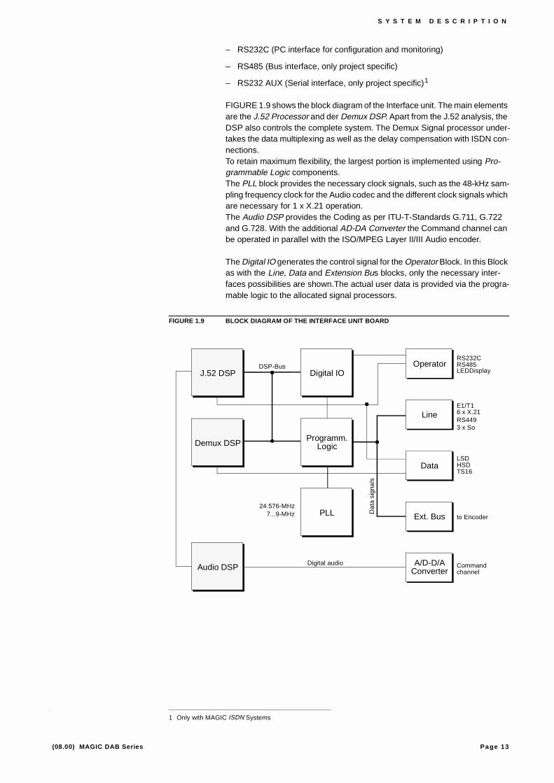
FIGURE 1.9 shows the block diagram of the Interface unit. The main elements are the J.52 Processor and der Demux DSP. Apart from the J.52 analysis, the DSP also controls the complete system. The Demux Signal processor under-takes the data multiplexing as well as the delay compensation with ISDN con-nections.To retain maximum flexibility, the largest portion is implemented using Pro-grammable Logic components.The PLL block provides the necessary clock signals, such as the 48-kHz sam-pling frequency clock for the Audio codec and the different clock signals which are necessary for 1 x X.21 operation.The Audio DSP provides the Coding as per ITU-T-Standards G.711, G.722 and G.728. With the additional AD-DA Converter the Command channel can be operated in parallel with the ISO/MPEG Layer II/III Audio encoder.
The Digital IO generates the control signal for the Operator Block. In this Block as with the Line, Data and Extension Bus blocks, only the necessary inter-faces possibilities are shown.The actual user data is provided via the progra-mable logic to the allocated signal processors.
FIGURE 1.9 BLOCK DIAGRAM OF THE INTERFACE UNIT BOARD
1 Only with MAGIC ISDN Systems
DSP-Bus Operator
Line
Data
Ext. Bus
A/D-D/AConverter
Demux DSP
Audio DSP
J.52 DSP
RS232CRS485LEDDisplay
E1/T16 x X.21
LSDHSD
to Encoder
Commandchannel
Digital audio
24.576-MHz7...9-MHz D
ata
sig
nals
Digital IO
Programm.Logic
PLL
RS449
TS16
3 x So

Page 14 (08.00) MAGIC DAB Series
S Y S T E M D E S C R I P T I O N
1.6 The ‘Audio encoder Layer II/III’ Board
The Audio Codec permits the transmission of audio signals with lower bitrates as is necessary for example, in the ISDN. In the process a reduction by a fac-tor of 11 with Layer III and by a factor of 6 with Layer II, without imparement of quality is achieved. The coding is in accordance with ISO/MPEG Layer II/III as per ISO/IEC 11172-3, as well as the DAB ETS300401 Standards.
Aside from the audio channel, an additional-data channel with a maximum data rate of 9.6-kbaud, 38.4-kbaud with DAB, is available to transmit, for ex-ample, program associated information.
For the audio input signal an l AES/EBU professional digital interface with Sample Rate Converter as well as an electronically symmetrical analogue au-dio interface are provided .
FIGURE 1.10 shows the Block diagram of the board. The Encoder part is im-plemented with four signal processors. Based on this relatively high proces-sing power the hardware is in a positon to implement future coding algorithms.The Host processor is the controlling element of the board. This microproces-sor downloads the software from the Flash-Eproms to run, monitor and confi-gure the encoder. The analogue part is controlled over a special control regi-ster (level). The 32-kHz and the 48-kHz sampling frequencies are always synchronised with the network clock. When a digital audio source is used the clock for the audio source is synchronised with the network clock by means of a sampling rate converter (SRC). The data exchange with the interface unit is over the Ex-tension Bus. Aside from the data and clock signals (RXD, TXD, X21_CLK, CLK_SYN), the data request signals (TXD_V, RXD_V) as well as the bi-direc-tional communication channel (XD, XC) are available.
FIGURE 1.10 BLOCK DIAGRAM OF THE AUDIO ENCODER LAYER II/III BOARD
V.11
TTL
V.11
TTL
V.24
TTL
V.11
TTLUART
PCB Address
Host
Control
AES/EBU
Select Sampling ClkRXD
Level
Sampl. Clk (32-kHz)
RTS
TXD
TXD_V
X21_Clk
CLK_SYN
TXD
XD
XC
Sampl. Clk (48-kHz)
Encoded Data
Sampling Clock
ClockDig. Audio
Host bus
Host bus
Add. Data
Ext. Bus
Ext. Bus
Ext. Bus Data
PLL Clock Mux
SRCEncoder
Layer II/III
MUX
Anal. Audio
A
D
Data
Clock
Sel. Source
Select Source
Hostbus
AES/EBU Modul
Page 15 (08.00) MAGIC DAB Series
S Y S T E M D E S C R I P T I O N
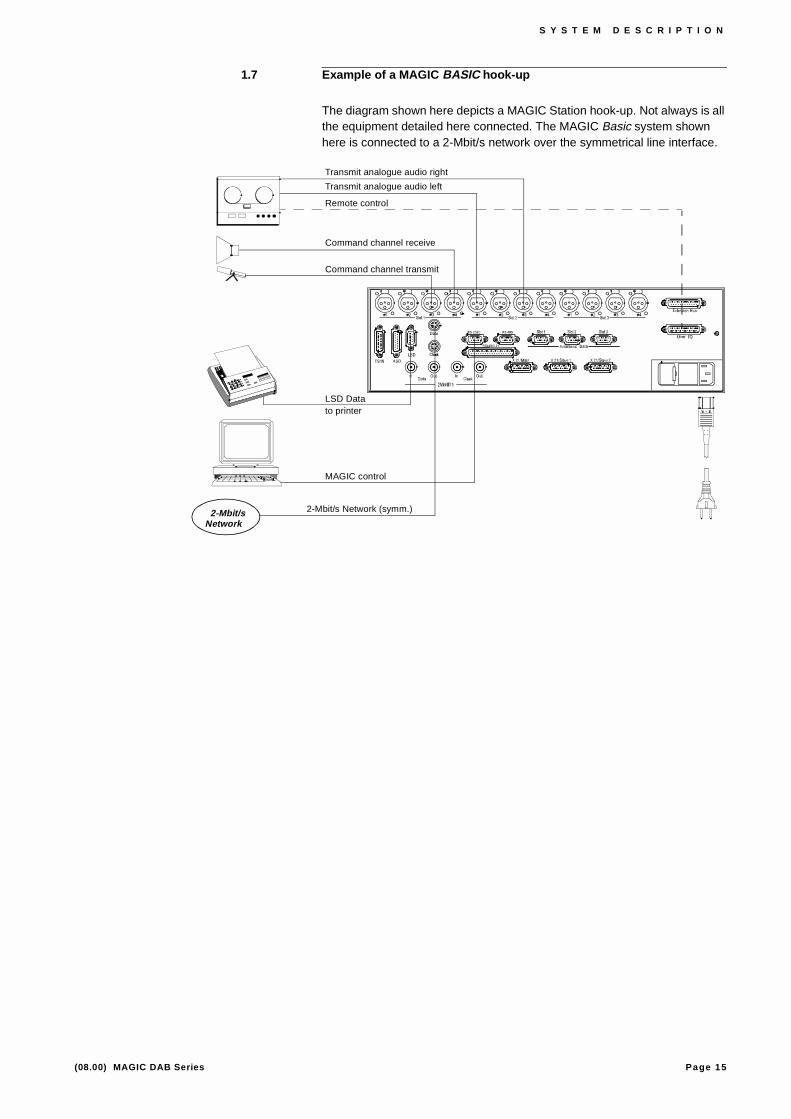
1.7 Example of a MAGIC BASIC hook-up
The diagram shown here depicts a MAGIC Station hook-up. Not always is all the equipment detailed here connected. The MAGIC Basic system shown here is connected to a 2-Mbit/s network over the symmetrical line interface.
LSD Data
MAGIC control
Transmit analogue audio right
2-Mbit/s Network (symm.)
Command channel transmit
Command channel receive
Transmit analogue audio left
to printer
Remote control
2-Mbit/sNetwork

Page 16 (08.00) MAGIC DAB Series
S Y S T E M D E S C R I P T I O N

Page 17 (08.00) MAGIC DAB Series
O P E R A T I O N O F T H E M A G I C S Y S T E M
2 O P E R A T I O N O F T H E M A G I C S Y S T E M
This chapter describes the operation of an individual MAGIC BASIC unit equipped as follows:
– Slot 1: Interface unit
– Slot 2: Audio Encoder Layer II/III
– Slot 3: free
When a MAGIC System with more than two Encoders is required, as well as that described herein, an Extension Bus must be used to connect the indivi-dual units together into a single MAGIC (see PARAGRAPH 2.9).
2.1 Installation of the MAGIC Audio Encoders
With measurements of (B × H × T) of 439 mm × 133 mm (3 U) × 395 mm, the MAGIC System can be used as table top equipment or by using the mounting angles, it can be built in to a 19“ or ETSI rack.
The stated measurements are without the 19“ - ETSI mounting angles and wi-thout the feet for the table mounted version. When installed care is to be taken that the minimum bending radius of the connected cables is not reduced.
With the installation care should be taken that the MAGIC Audio Encoder has a sufficient airflow. It is recommended that a clearance of approx. 3cm is main-tained. Generally, the surrounding temperature of the MAGIC System should not lie outside the range +5°C to +40°C. Special care should be taken when the MAGIC Audio Encoder is built into furniture.
During operation the Relative Humidity should be between 5% and 85%. Ope-ration of the MAGIC Audio Encoder outside these limits is not permissable and will invalidate the guarantee.
2.2 Choice of Network Interface
The MAGIC Audio Encoder offers the user a selection of Network Interfaces. Always however, only one type of Interface can be active. Choose the relevant network Interface to suit your requirement.
The following overview shows the typical uses of the different network inter-faces of the MAGIC-System:
Network Interface Use
X.21 Main Data interface n × 64-kbit/s, n = 1 to 30,
Block allocation required
1 to 6 × X.21 Data interfaces each with 64-kbit/s, Dialing procedure for Terminal Adapter and delay compensation between the individual channels.
RS449 Data interface n × 64-kbit/s, n = 1 to 30,
Block allocation required
Page 18 (08.00) MAGIC DAB Series
O P E R A T I O N O F T H E M A G I C S Y S T E M
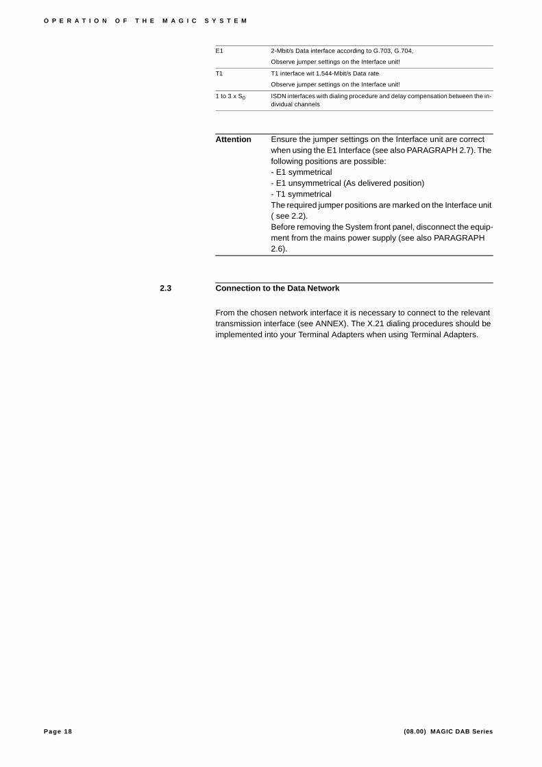
Attention Ensure the jumper settings on the Interface unit are correct when using the E1 Interface (see also PARAGRAPH 2.7). The following positions are possible:- E1 symmetrical- E1 unsymmetrical (As delivered position)- T1 symmetricalThe required jumper positions are marked on the Interface unit ( see 2.2). Before removing the System front panel, disconnect the equip-ment from the mains power supply (see also PARAGRAPH 2.6).
2.3 Connection to the Data Network
From the chosen network interface it is necessary to connect to the relevant transmission interface (see ANNEX). The X.21 dialing procedures should be implemented into your Terminal Adapters when using Terminal Adapters.
E1 2-Mbit/s Data interface according to G.703, G.704,
Observe jumper settings on the Interface unit!
T1 T1 interface wit 1.544-Mbit/s Data rate
Observe jumper settings on the Interface unit!
1 to 3 x S0 ISDN interfaces with dialing procedure and delay compensation between the in-dividual channels
Page 19 (08.00) MAGIC DAB Series
O P E R A T I O N O F T H E M A G I C S Y S T E M
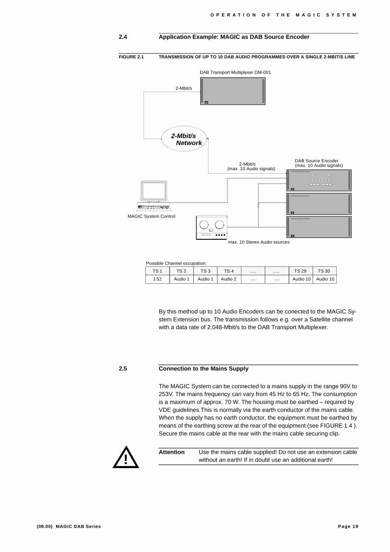
2.4 Application Example: MAGIC as DAB Source Encoder
FIGURE 2.1 TRANSMISSION OF UP TO 10 DAB AUDIO PROGRAMMES OVER A SINGLE 2-MBIT/S LINE
By this method up to 10 Audio Encoders can be conected to the MAGIC Sy-stem Extension bus. The transmission follows e.g. over a Satellite channel with a data rate of 2.048-Mbit/s to the DAB Transport Multiplexer.
2.5 Connection to the Mains Supply
The MAGIC System can be connected to a mains supply in the range 90V to 253V. The mains frequency can vary from 45 Hz to 65 Hz. The consumption is a maximum of approx. 70 W. The housing must be earthed – required by VDE guidelines.This is normally via the earth conductor of the mains cable. When the supply has no earth conductor, the equipment must be earthed by means of the earthing screw at the rear of the equipment (see FIGURE 1.4 ). Secure the mains cable at the rear with the mains cable securing clip.
Attention Use the mains cable supplied! Do not use an extension cable without an earth! If in doubt use an additional earth!
MAGIC System Control
max. 10 Stereo Audio sources
2-Mbit/s(max. 10 Audio signals)
TS 1 TS 2 TS 3 TS 4 TS 30TS 29..........
J.52 Audio 1 Audio 1 Audio 2 Audio 10Audio 10..........
Possible Channel occupation:
DAB Source Encoder MAGIC-B
DAB Source Encoder MAGIC-E
DAB Source Encoder MAGIC-E
DAB Source Encoder(max. 10 Audio signals)
2-Mbit/sNetwork
2-Mbit/s
DAB Transport Multiplexer DM-001
!

Page 20 (08.00) MAGIC DAB Series
O P E R A T I O N O F T H E M A G I C S Y S T E M
2.6 Opening the Equipment
Attention Before opening the equipment remove the mains plug!
Although most of the equipment configurations can be changed externally by software, it may be necessary to open the equipment.To do so remove the four screws on the front panel. The panel can then be pulled off with the handles. The LED Display unit can likewise be pulled out. The individual circuit boards are mounted horizontally and can be pulled out as well as pushed in by lightly pulling the lifting levers.
Attention Dangerous voltages can be present on the power supply for several minutes after removal. Therefore on no account touch the components or the soldering points on the power supply module after its removal.
The assembly of the system can be seen from the Table in PARAGRAPH 1.3.
The re-assembly of the equipment follows in reverse order.
!

Page 21 (08.00) MAGIC DAB Series
O P E R A T I O N O F T H E M A G I C S Y S T E M
2.7 Setting up of the G.703 Network Interface
The following three operational modes according to G.703 (E1 as well as T1) are selectable for the Network Interface:
– E1 Interface symmetrical,
– E1 Interface asymmetrical (as delivered setting) or
– T1 Interface symmetrical
Each of these modes must be configured on the Interface Unit by means of jumpers (see FIGURE 2.2) before it can be acivated by the software.
It is important to note that all jumpers are always on the same setting.
FIGURE 2.2 LAYOUT OF THE JUMPERS ON THE INTERFACE UNIT
SYMUNSYMT1
SYMUNSYM
T1CLK-OUT CLK-IN DATA-IN DATA-OUT

Page 22 (08.00) MAGIC DAB Series
O P E R A T I O N O F T H E M A G I C S Y S T E M
2.8 Configuration of the Encoder Address
The encoder address for each Encoder unit must be set by an 8-pole DIL switch (see FIGURE 2.3). After that make sure that the unit within a system (BASIC/ISDN or EXTENSION) always has the same encoder adress and that different units always have different encoder addresses. Should the Equipment configuration read out in the UNIT Panel not correspond with the actual or if not all boards are shown, it is possible that the encoder address is not properly set.
FIGURE 2.3 LAYOUT OF THE DIL SWITCHES ON THE ENCODER BOARD
Each unit with its encoder address according to TABLE 2.1 can be seen as described in the User Software.
Tip Always set the BASIC unit equipment number to 0000b to be sure that this is unit 0.
TABLE 2.1 ALLOCATING THE ENCODER ADDRESS WITH THE SETTINGS OF THE DIL SWITCH
DIL Switch UNIT
5 6 7 8
0 0 0 0 0
1 0 0 0 1
0 1 0 0 2
1 1 0 0 3
0 0 1 0 4
10
Bits 5, 6, 7 & 8 for settingthe Encoder Address

Page 23 (08.00) MAGIC DAB Series
O P E R A T I O N O F T H E M A G I C S Y S T E M
Page 24 (08.00) MAGIC DAB Series
O P E R A T I O N O F T H E M A G I C S Y S T E M
2.9 Connection of the MAGIC units to each other
All MAGIC units are connected to each other over the Extension Bus. Up to four units can be connected using the supplied screened connection cable.
Alternatively you can make up a connection cable yourself. Stand all units in the required location. Use a 25 conductor flat cable and a Sub-D female plug with crimp connections. Take the end of the flat cable with the female plug. Plug this into the corresponding male socket on the BASIC unit and run the flat cable to the first expansion unit. From there use a further Sub-D female plug, but do not cut the cable. Continue the cable to the other EXTENSION units one at a time using additional Sub-D female plugs.
Note Don’t make the individual cable steps too short so that the MA-GIC units can be moved later. Put the last Sub-D female plug right at the end of the cable so that the conductors cannot be shorted.
After that check that all Sub-D female plugs have the same ori-entation relative to the cable (e.g. the red mark on the cable to pin 1).
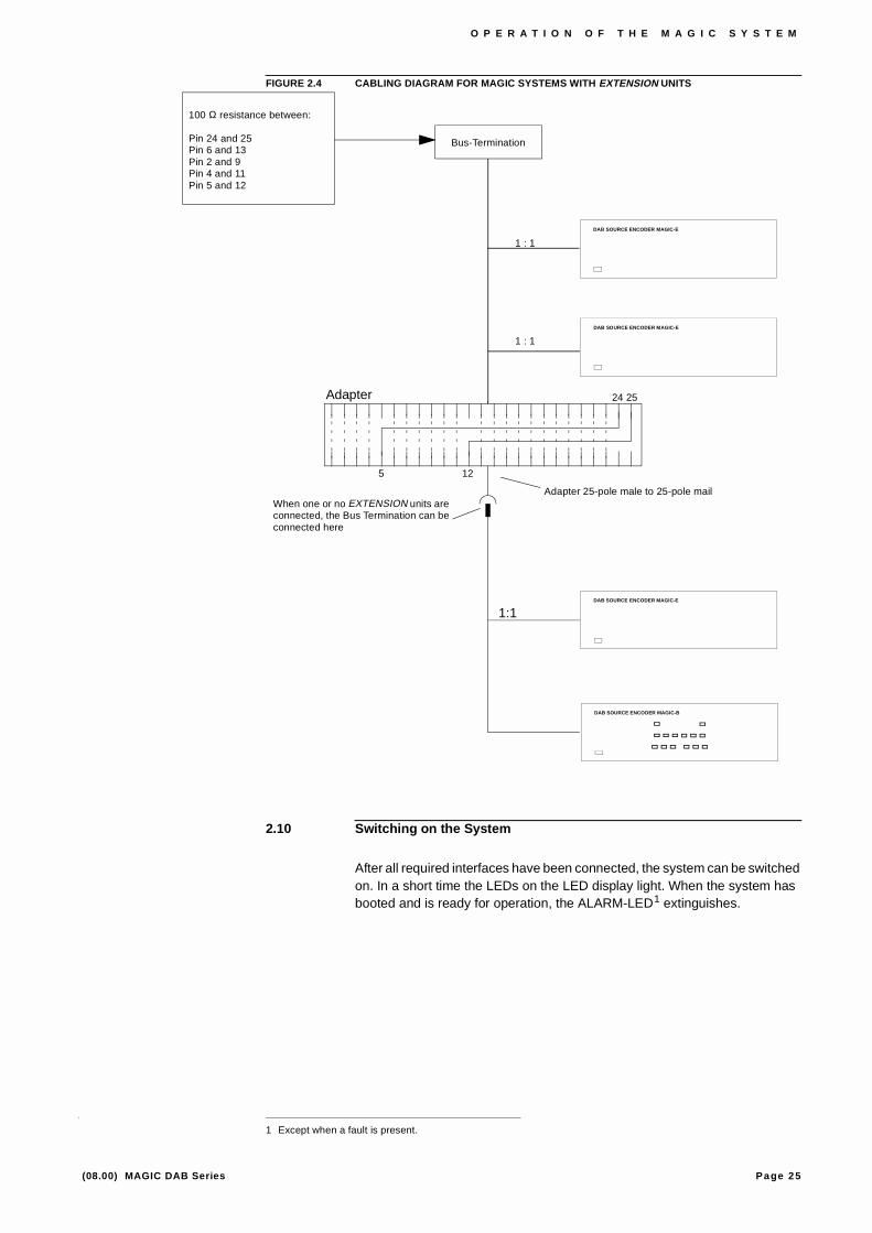
Should more than five Encoder boards be connected, the network synchroni-sing clock for additional units must be derived from another driver unit. There-fore for these units the conductors from pins 5 and 12 of the BASIC unit must be connected to pins 24 and 25 of the EXTENSION units. Accordingly there is an adapter shown in the following diagram to switch between the two exten-sion cables. If more than 5 Encoder boards are connected in a single system, an appropriate Bus termination is necessary (FIGURE 2.4).
Page 25 (08.00) MAGIC DAB Series
O P E R A T I O N O F T H E M A G I C S Y S T E M
FIGURE 2.4 CABLING DIAGRAM FOR MAGIC SYSTEMS WITH EXTENSION UNITS
2.10 Switching on the System
After all required interfaces have been connected, the system can be switched on. In a short time the LEDs on the LED display light. When the system has booted and is ready for operation, the ALARM-LED1 extinguishes.
1 Except when a fault is present.
Bus-Termination
1:1
Adapter
When one or no EXTENSION units are connected, the Bus Termination can be connected here
100 Ω resistance between:
Pin 24 and 25Pin 6 and 13Pin 2 and 9Pin 4 and 11Pin 5 and 12
1 : 1
1 : 1
24 25
5 12
Adapter 25-pole male to 25-pole mail
DAB SOURCE ENCODER MAGIC-E
DAB SOURCE ENCODER MAGIC-E
DAB SOURCE ENCODER MAGIC-E
DAB SOURCE ENCODER MAGIC-B

Page 26 (08.00) MAGIC DAB Series
O P E R A T I O N O F T H E M A G I C S Y S T E M
Page 27 (08.00) MAGIC DAB Series
L E D D I S P L A Y
3 L E D D I S P L A Y
In the following sections the LED Displays of the MAGIC BASIC and MAGIC ISDN variants are presented and the purpose of each LED explained.
3.1 LED Display MAGIC BASIC
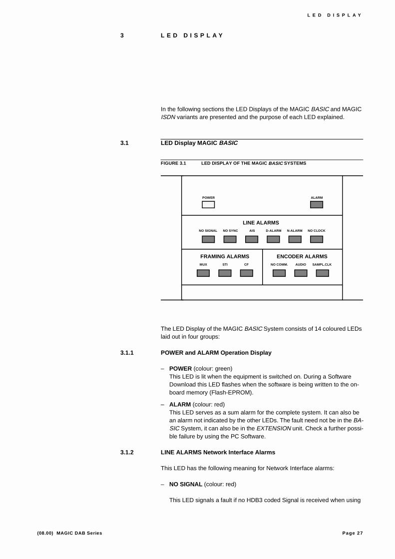
FIGURE 3.1 LED DISPLAY OF THE MAGIC BASIC SYSTEMS
The LED Display of the MAGIC BASIC System consists of 14 coloured LEDs laid out in four groups:
3.1.1 POWER and ALARM Operation Display
– POWER (colour: green)This LED is lit when the equipment is switched on. During a Software Download this LED flashes when the software is being written to the on-board memory (Flash-EPROM).
– ALARM (colour: red)This LED serves as a sum alarm for the complete system. It can also be an alarm not indicated by the other LEDs. The fault need not be in the BA-SIC System, it can also be in the EXTENSION unit. Check a further possi-ble failure by using the PC Software.
3.1.2 LINE ALARMS Network Interface Alarms
This LED has the following meaning for Network Interface alarms:
– NO SIGNAL (colour: red)
This LED signals a fault if no HDB3 coded Signal is received when using
POWER ALARM
NO SIGNAL NO SYNC AIS D-ALARM N-ALARM NO CLOCK
MUX STI CF NO COMM. AUDIO SAMPL.CLK
LINE ALARMS
FRAMING ALARMS ENCODER ALARMS
Page 28 (08.00) MAGIC DAB Series
L E D D I S P L A Y
the E1/T1 Interface (2-Mbit/s,1.544-Mbit/s) . No fault is indicated in uni-di-rectional operation.
– NO SYNChronisation (colour: red)
This LED indicates a fault if no Framing signal is found when using the E1/T1Interface (2-Mbit/s,1.544-Mbit/s). No fault is indicated in uni-directio-nal operation.
– Alarm Indication Signal (colour: red)
This LED indicates a fault if two or less ’0’ are received within a time span of 2 Frames when using the E1/T1Interface (2-Mbit/s,1.544-Mbit/s). No fault is indicated in uni-directional operation.
– Prompt maintenance ALARM (colour: red)
This LED indicates a fault if the Bit Error Rate exceeds a value of 10e-03 when using the E1/T1Interface (2-Mbit/s,1.544-Mbit/s). No fault is indica-ted in uni-directional operation.
– Defered maintenance alarm ALARM (colour: red)
This LED indicates a fault if the Bit Error Rate exceeds a value of 10e-06 when using the E1/T1Interface (2-Mbit/s,1.544-Mbit/s). No fault is indica-ted in uni-directional operation.
– NO CLOCK (colour: red)
This LED indicates a fault if no network clock can be detected when using either the E1/T1Interface (2-Mbit/s,1.544-Mbit/s) with an external clock in-put or the X.21 Interface.
3.1.3 Frame Signal Alarms
– J.52 (colour: red)
This LED indicates a fault if no J.52 Frame is recognised when using the ITU-T J.52 Synchronisation procedure. No fault is indicated in uni-directio-nal operation.
– Service Transport Interface (colour: red)
This LED indicates a fault if the STI back-channel frame cannot be found when using the STI standard. No fault is indicated if a back-channel is not available.
– Control File (colour: red)
This LED indicates a fault if a failure is detected in the Control File when using the STI Standard. No fault is indicated if a back-channel is not availa-ble.

Page 29 (08.00) MAGIC DAB Series
L E D D I S P L A Y
3.1.4 Encoder Alarms
– NO COMMunication (colour: red)
This LED indicates a fault if an Interface board on one of the Encoders in the system can no longer be addressed. Short time illumination of this LED is possible during normal operation.
– AUDIO (colour: red)
This LED indicates a fault when the MPEG Frame of one of the Encoders can no longer be detected by the interface board. This monitoring is only active in STI operation.
– SAMPL ing CLocK (colour: red)
This LED indicates a fault if the sampling frequency of one of the Encoder boards does not correspond to the selected sampling frequency. The cause can also be from an externally supplied clock.
Page 30 (08.00) MAGIC DAB Series
L E D D I S P L A Y
3.2 LED Display MAGIC ISDN
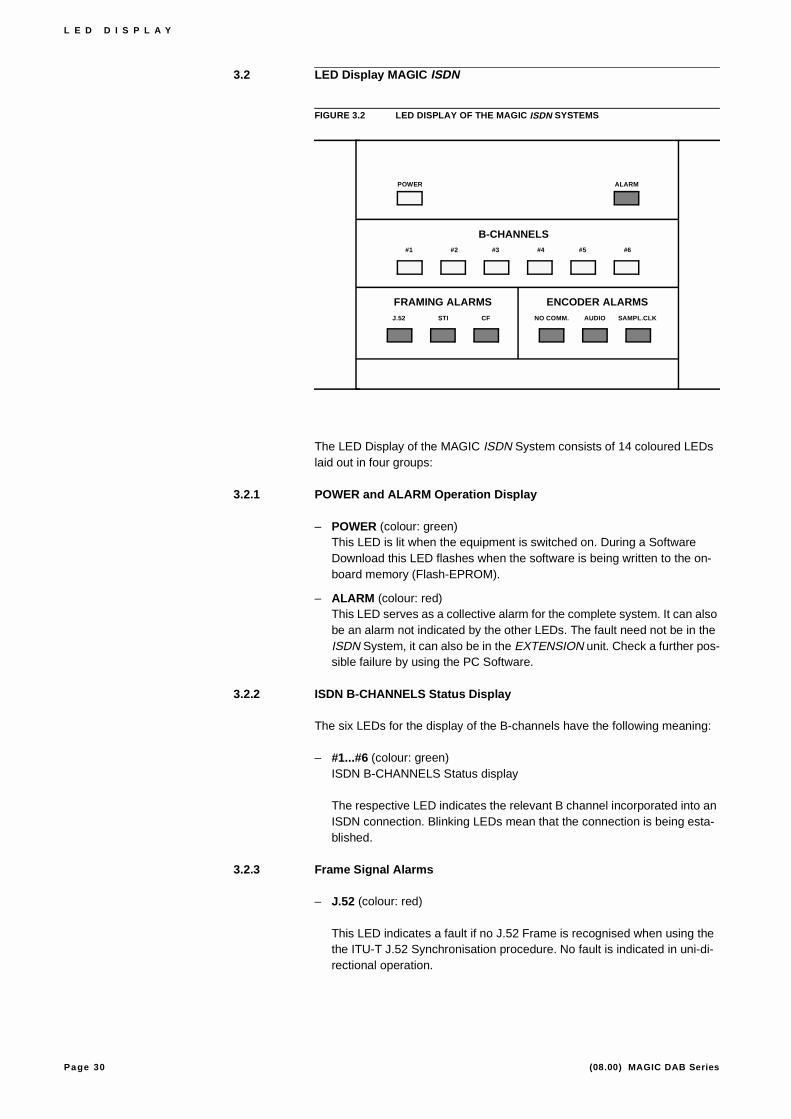
FIGURE 3.2 LED DISPLAY OF THE MAGIC ISDN SYSTEMS
The LED Display of the MAGIC ISDN System consists of 14 coloured LEDs laid out in four groups:
3.2.1 POWER and ALARM Operation Display
– POWER (colour: green)This LED is lit when the equipment is switched on. During a Software Download this LED flashes when the software is being written to the on-board memory (Flash-EPROM).
– ALARM (colour: red)This LED serves as a collective alarm for the complete system. It can also be an alarm not indicated by the other LEDs. The fault need not be in the ISDN System, it can also be in the EXTENSION unit. Check a further pos-sible failure by using the PC Software.
3.2.2 ISDN B-CHANNELS Status Display
The six LEDs for the display of the B-channels have the following meaning:
– #1...#6 (colour: green)ISDN B-CHANNELS Status display
The respective LED indicates the relevant B channel incorporated into an ISDN connection. Blinking LEDs mean that the connection is being esta-blished.
3.2.3 Frame Signal Alarms
– J.52 (colour: red)
This LED indicates a fault if no J.52 Frame is recognised when using the the ITU-T J.52 Synchronisation procedure. No fault is indicated in uni-di-rectional operation.
POWER ALARM
#1 #2 #3 #4 #5 #6
J.52 STI CF NO COMM. AUDIO SAMPL.CLK
B-CHANNELS
FRAMING ALARMS ENCODER ALARMS
Page 31 (08.00) MAGIC DAB Series
L E D D I S P L A Y
– Service Transport Interface (colour: red)
This LED indicates a fault if the STI back-channel Frame cannot be found when using the STI Standard. No fault is indicated if a back-channel is not available.
– Control File (colour: red)
This LED indicates a fault if a failure is detected in the Control File when using the STI Standard. No fault is indicated if a back-channel is not availa-ble.
3.2.4 Encoder Alarms
– NO COMMunication (colour: red)
This LED indicates a fault if an Interface board on one of the Encoders in the system can no longer be addressed. Short time illumination of this LED is possible during normal operation.
– AUDIO (colour: red)
This LED indicates a fault when the MPEG Frame of one of the Encoders can no longer be detected by the interface board. This monitoring is only active in STI operation.
– SAMPL ing CLocK (colour: red)
This LED indicates a fault if the sampling frequency of one of the Encoder boards does not correspond to the selected sampling frequency. The cause can also be from an externally supplied clock.

Page 32 (08.00) MAGIC DAB Series
L E D D I S P L A Y

Page 33 (08.00) MAGIC DAB Series
A N N E X
A N N E X 1 T E C H N I C A L D A T A
A1.1 Interface Unit with various Network Accesses
Signalling /Synchronisation
ITU-T Rec. J.52 (H.221/H.242)ITU-T Rec. J.52 (H.331) for uni-directional connectionsService Transport Interface STI1
Coding algorithms
ITU-T Recommendation G.722, G.711 orGSM (3.1-kHz coded at 16-kbit/s )G.728 (3.1-kHz coded at 16-kbit/s)
Network interfaces
1 × X.21 Data rate n × 64-kbit/s to 1920-kbit/s
6 × X.212 Data rate 64-kbit/s at a time
RS 4492 Data rate n × 64-kbit/s to 1920-kbit/s
2-Mbit/s Interface2 to G.703, G.704
T1 Interface2
Data rate n × 64-kbit/s (n=1...24)
3 × S03 Data rates 2 × 64 + 1 × 16-kbit/s per S0
Protocols 1TR6, DSS-1
Additional Data Interfaces
LSD-channel Data interface to 64-kbit/s acc. to RS232C with bit rate adaption
HSD-channel X.21-Data Interfacefor Data rates from 64-kbit/s to 1920-kbit/s(at present 64-kbit/s)
TS16-channel Drop/Insert-interface 64-kbit/s-Timeslot according to X.21
1 optional
2 only MAGIC BASIC
3 only MAGIC ISDN

Page 34 (08.00) MAGIC DAB Series
A N N E X
Audio Interface
electronic, symmetrical InputNominal level 2,75 dBuImpedance Input >12 kΩ
Operator Interface
Operator Interface RS232C, TTL I/O Interface, user pro-grammable, Control current max 5 mA per channel
Bus System
Internal Bus
Channel Numbering
variable, dependant on configuration and allocation e.g..max. 20 Mono channelsor 10 Stereo channels
Clock generation/Clock recovery
Clock recovery from the received data stream, Internal clock or externally provided clock
A1.2 Audio Encoder Layer II / III
Coding Standard
ISO/MPEG2 Layer II to ISO/IEC 11172-3DAB-Mode ETS 300 401
Number of Channels
2 × mono or1 × stereo
Data Rates
Layer II: 8-kbit/s to 384-kbit/sSampling Frequency
Analogue 24-kHz and 48-kHz (selectable)by optional digital Input:with sampling rate selector 31...49-kHz
Operational Modes
Mono L, Mono R, Mono (L+R)/2, Dual channel, Stereo, Joint Stereo
Data Interfaces
RS 232C for Add. Data (variable Baudrate)

Page 35 (08.00) MAGIC DAB Series
A N N E X
Failure Checks
CRC16-Check in ISO/MPEG-Data stream (switchable)
Measurement with Failure Checks
Mute/Retry
Bus System
Internal Bus
Analogue Part
Audio Interface
Analogue symmetrical Audio interfaceInput impedance 600 Ω/15kΩ (selectable)
Nominal level –6 dBu bto+12 dBu, (selectable)
Over driving reserve +6 dB
Optional digital acc. to AES/EBU prof. with sampling frequency selection
Level Monotoring
Inputs left channel, right channel
Speech Restriction: –24 dB under nominal level
Emphasis
none
Frequency Range
Without Coding: 20-Hz to 20-kHz
with Coding: upper Band boundary dependson selected Data rate
THD:
K2 + K3 ≤ 0,025 %
Signal/Noise Ratio
<80 dB unweighted, referredto max. Output level
Crosstalk (L ↔R)
<80 dB to f=10-kHz

Page 36 (08.00) MAGIC DAB Series
A N N E X
Level Deviation
± 0.2 dB over the complete frequency range
A1.3 Power Supply
AC voltage
90 V to 253 V
Frequency
50/60 Hz
Power consumption
Configuration dependent, typically 70 VA
A1.4 Dimensions
Height
3 U (133 mm)
Width
449 mm (19"-rack)
Max. depth
450 mm
Weight
Configuration dependent, typ. approx. 10 kg
A1.5 Miscellaneous
EMV-Safety
VDE 0878 Boundary value Class B
Electrical Safety
EN 60950
TABLE 1.1 DELAY TIMES AT 48-kHZ
Data rate Layer II
64-kbit/s (Mono) 145 ms
128-kbit/s (Mono) 140 ms
192-kbit/s (Stereo) 135 ms
256-kbit/s (Stereo) 130 ms
320-kbit/s (Stereo) 130 ms
384-kbit/s (Stereo) 130 ms

Page 37 (08.00) MAGIC DAB Series
A N N E X
Noise
max. 30 dBA
Temperature
+5°C to 40 °C
Rel. Humidity
5 % to 85 %

Page 38 (08.00) MAGIC DAB Series
A N N E X
Page 39 (08.00) MAGIC DAB Series
A N N E X
A N N E X 2 I N T E R F A C E S
All Interfaces for the different system components are described below:
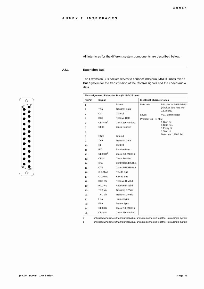
A2.1 Extension Bus
The Extension Bus socket serves to connect individual MAGIC units over a Bus System for the transmission of the Control signals and the coded audio data.
Pin assignment: Extension Bus (SUB-D 25 pole)
PinPin Signal Electrical Characteristics
1 Screen Data rate: 64-kbit/s to 2.048-Mbit/s(Abolute data rate withJ.52 Data)
Level: V.11, symmetrical
Protocol fo r RS-485:1 Start bit8 Data bits1 Parity bit1 Stop bitData rate: 19200 Bd
2 TXa Transmit Data
3 Ca Control
4 RXa Receive Data
5 CLK48aa Clock 256×48-kHz
a only used when more than four individual units are connected together into a single system
6 CLKa Clock Receive
7
8 GND Ground
9 TXb Transmit Data
10 Cb Control
11 RXb Receive Data
12 CLK48bb Clock 256×48-kHz
b only used when more than four individual units are connected together into a single system
13 CLKb Clock Receive
14 CTa Control RS485 Bus
15 CTb Control RS485 Bus
16 C DATAa RS485 Bus
17 C DATAb RS485 Bus
18 RXD Va Receive D Valid
19 RXD Vb Receive D Valid
20 TXD Va Transmit D Valid
21 TXD Vb Transmit D Valid
22 FSa Frame Sync
23 FSb Frame Sync
24 CLK48a Clock 256×48-kHz
25 CLK48b Clock 256×48-kHz
1
13
14
25

Page 40 (08.00) MAGIC DAB Series
A N N E X
A2.2 Audio Interface
A2.2.1 AES/EBU Interface
The AES/EBU Interface serves to transmit the digital Audio and Additional Data.
A2.2.2 Analogue Audio Interface
A2.3 Network Interfaces
A2.3.1 So Interfaces
A2.3.2 X.21 Interfaces
The MAGIC Audio encoder BASIC has up to six X.21 Interfaces available. Three of these X.21 Interfaces are directly accessible on the rear side. The other three are accessed through the RS449 Interface and the TS16-Data In-terface via adapter cables.
Socket: Audio Digital Interface (XLR)
Pin Signal Electrical Characteristics
Input Level: V.11, symmetrical
1 GND Screen
2 RXD a Receive Data a
3 RXD b Receive Data b
Clock output
1 GND Screen
2 CLK a Clock a
3 CLK b Clock b
Socket: Audio Analogue Interface (XLR)
Pin Signal Electrical Characteristics
1 Screen Level:Input –6 dBu to+12 dBuImpedance: Input >12 kΩ /600 Ω.
2 Audio a In
3 Audio b In
Socket: Western Socket, 8-pole
Pin Signal Electrical Characteristics
1 not used Recommendation: I.430
Bitrate: B Channel: 2x 64-kbit/s
D Channel: 16-kbit/s2 not used
3 TX
4 RX
5 RX
6 TX
7 not used
8 not used
Pus
h 1
23
Pus
h 1
23
1 8
Page 41 (08.00) MAGIC DAB Series
A N N E X
The X.21 Interfaces provide the access to the transmission network and are genuine Data Interfaces with Bit timing (Byte timing can be used if it is provi-ded by the network).
The X.21 Interfaces have a choice of operational Modes which are fully des-cribed below.
X.21 Mode 1
In this operational mode only the „X.21/Main“ Interface with a Data rate from 64 to1920-kbit/s is available. The X.21 Interface is a DTE interface and ex-pects as a transport medium one en-block assembled bitstream.
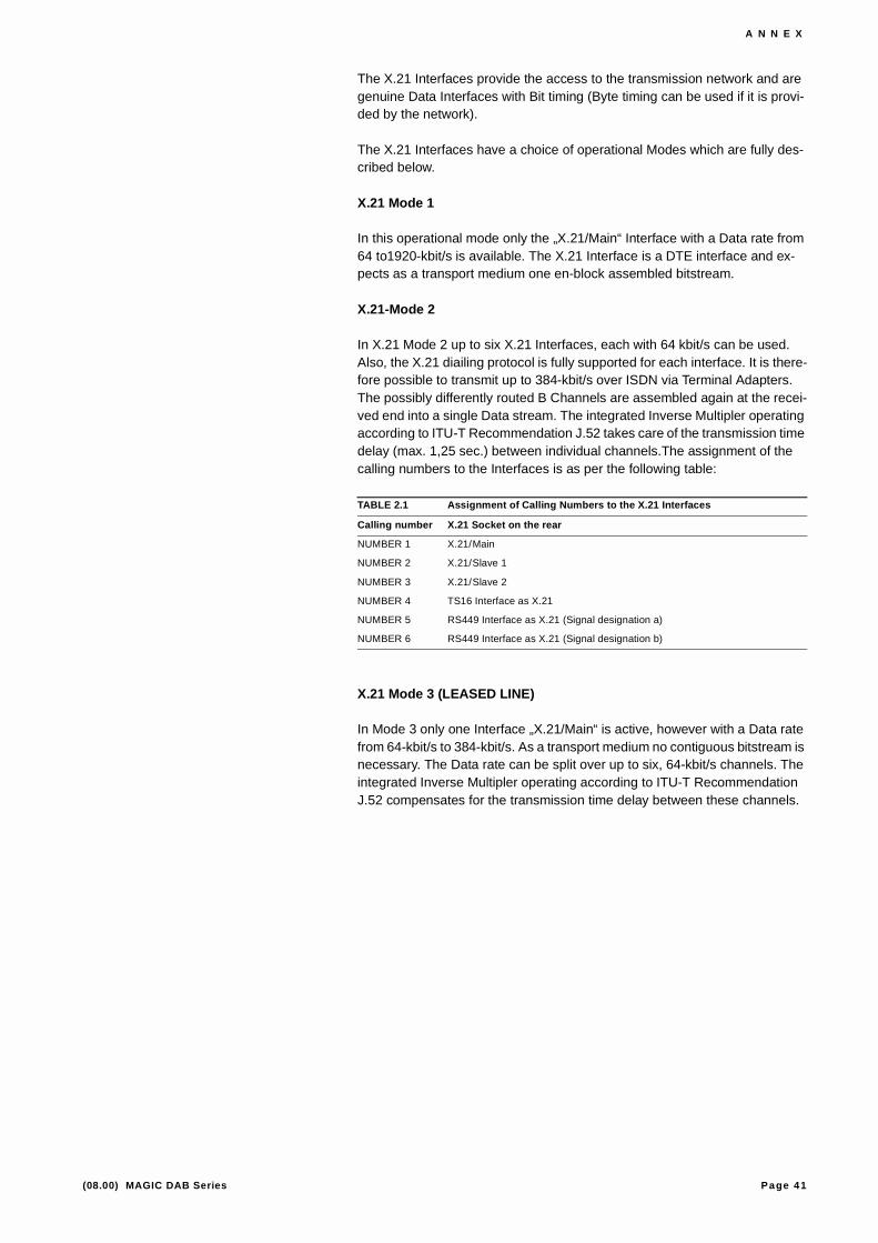
X.21-Mode 2
In X.21 Mode 2 up to six X.21 Interfaces, each with 64 kbit/s can be used. Also, the X.21 diailing protocol is fully supported for each interface. It is there-fore possible to transmit up to 384-kbit/s over ISDN via Terminal Adapters. The possibly differently routed B Channels are assembled again at the recei-ved end into a single Data stream. The integrated Inverse Multipler operating according to ITU-T Recommendation J.52 takes care of the transmission time delay (max. 1,25 sec.) between individual channels.The assignment of the calling numbers to the Interfaces is as per the following table:
X.21 Mode 3 (LEASED LINE)
In Mode 3 only one Interface „X.21/Main“ is active, however with a Data rate from 64-kbit/s to 384-kbit/s. As a transport medium no contiguous bitstream is necessary. The Data rate can be split over up to six, 64-kbit/s channels. The integrated Inverse Multipler operating according to ITU-T Recommendation J.52 compensates for the transmission time delay between these channels.
TABLE 2.1 Assignment of Calling Numbers to the X.21 Interfaces
Calling number X.21 Socket on the rear
NUMBER 1 X.21/Main
NUMBER 2 X.21/Slave 1
NUMBER 3 X.21/Slave 2
NUMBER 4 TS16 Interface as X.21
NUMBER 5 RS449 Interface as X.21 (Signal designation a)
NUMBER 6 RS449 Interface as X.21 (Signal designation b)
Page 42 (08.00) MAGIC DAB Series
A N N E X
A2.3.3 RS449 Interface
The RS449 Interface is type DTE and can be driven at speeds from 64-kbit/s to 1920-kbit/s1. The Synchronisation is effected as Loop Timing. Also, since this Interface has one contiguous bitstream, a transmission delay between single 64-kbit/s channels is not forseen. The areas of major use for the RS449 Interface are Satellite transmission and Time Division Multiplexing on in-house networks. It is to be noted that the Send and Receive clocks must be identical.
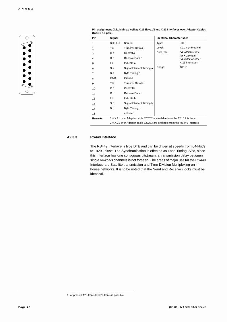
Pin assignment: X.21/Main as well as X.21Slave1/2 and X.21 Interfaces over Adapter Cables(SUB-D 15-pole)
Pin Signal Electrical Characteristics
1 SHIELD Screen Type: DTE
Level: V.11, symmetrical
Data rate: 64 to1920-kbit/sfor X.21/Main64-kbit/s for otherX.21 Interfaces
Range: 100 m
2 T a Transmit Data a
3 C a Control a
4 R a Receive Data a
5 I a Indicate a
6 S a Signal Element Timing a
7 B a Byte Timing a
8 GND Ground
9 T b Transmit Data b
10 C b Control b
11 R b Receive Data b
12 I b Indicate b
13 S b Signal Element Timing b
14 B b Byte Timing b
15 not used
Remarks: 1 × X.21 over Adapter cable 328252 is available from the TS16 Interface
2 × X.21 over Adapter cable 328253 are available from the RS449 Interface
1 at present 128-kbit/s to1920-kbit/s is possible
1
8
9
15

Page 43 (08.00) MAGIC DAB Series
A N N E X
Pin Assignment: RS449 (SUB-D 37-pole)
Pin Signal Electrical Characteristics
1 SHIELD Screen Type: DTE
Data rate: 64 to1920-kbit/s
Range: 100 m
Level: V.11, symmetrical
2 (SI) Signal rate indicator (n.c.)
3 not used
4 SD a Send Data a
5 ST a Send Timing a= RT
6 RD a Receive Data a
7 RS a Request to Send a
8 RT a Receive Timing a= ST
9 CS a Clear to Send a
10 (LL) Local loopback (n.c.)
11 (DM a) Data mode (n.c.)
12 TR a Terminal Ready a
13 RR a Receiver ready a
14 (RL) Remote loopback (n.c.)
15 IC Incoming call
16 (SF/SR) Select freq./rate (n.c.)
17 TT a Transmit Timing a
18 (TM) Test mode (n.c.)
19 GND Signal ground
20 RC Receive common
21 not used
22 SD b Send Data b
23 ST b Send Timing b= RT
24 RD b Receive Data b
25 RS b Request to Send b
26 RT b Receive Timing b= ST
27 CS a Clear to Send b
28 (IS) Terminal in service (n.c.)
29 (DM b) Data mode (n.c.)
30 TR b Terminal Ready b
31 RR b Receiver ready b
32 (SS) Select standby(n.c.)
33 (SQ) Signal quality(n.c.)
34 (NS) New signal(n.c.)
35 TT b Transmit Timing b
36 (SB) Standby indicator(n.c.)
37 SC Send common
1937
120

Page 44 (08.00) MAGIC DAB Series
A N N E X
A2.3.4 E1 Interface
From this Interface a contiguous bitstream of 30 x 64-kbit/s user channels is available. Using software, the number of channels used can be selected from the Codec. The Timeslots are filled up in ascending order.
In E1, Timeslot 0 is used for Terminal Equipment - Network signalling i.e. the Frames Structure identification word and Timeslot 16 is reserved for dialing in-formation.
Dialing information can be transparently inserted into TS 16 via the TS16 Data Interface.
Pin Assignment: RS449 for X.21 Interface (SUB-D 37-pole)
Pin Signal Electrical Characteristics
1 SHIELD Screen Type: DTE
Level: V.11, symmetrical
Data rate: 64-kbit/s
Range: 100 m
2 not used
3 not used
4 T a 5 Transmit a
5 S a 6 Signal Element Timing a
6 R a 5 Receive a
7 C a 5 Control a
8 S a 5 Signal Element Timing a
9 R a 6 Receive a
10 not used
11 B a 5 Byte Timing
12 C a 6 Control a
13 I a 5 Indicate a
14 not used
15 I a 6 Indicate a
16 not used
17 T a 6 Transmit a
18 not used
19 GND Ground
20 I b 6 Indicate b
21 not used
22 T b 5 Transmit b
23 S b 6 Signal Element Timing b
24 R b 5 Receive b
25 C b 5 Control b
26 S b 5 Signal element Timing b
27 R b 6 Receive b
28 not used
29 B b5 Byte Timing b
30 C b 6 Control b
31 I b 5 Indicate b
32 not used
33 B a 6 Byte Timing a
34 not used
35 T b 6 Transmit b
36 B b 6 Byte Timing b
37 GND Ground
Remarks: X.21 are only available using the adapter cables 32825
1937
120

Page 45 (08.00) MAGIC DAB Series
A N N E X
As the J.52 information is only contained in the first timeslot (TS 1 for E1) the used channels must be assembled into a contiguous block. An ISDN Primary multiplexer connection is not suitable as here the user channels can be sent over different paths.
Unsymmetrical Interface ( E1 only)
Symmetrical Interface (E1 and T1)
A2.4 Data Interfaces
A2.4.1 HSD Interface
The HSD Channel is provided for the transmission of faster data.
Socke: Data in / Data Out (BNC)
Pin Signal Electrical Characteristics
1 Daten – F1 an / F1 ab Amplitude: 3 Vpp
Impedance: 75 Ω, asym.
Range: >100 m (for each cable)2 GND
Socket: Clock in / Clock Out (BNC)
Pin Signal Electrical Characteristics
1 Clock – T3 in / T3 out Amplitude: 0,5 to1,9 Vs0 (Input)1,5 Vs0 (Output)
Impedance: 75 Ω, asym.
Range: 100 m
2 GND
Socket: Data (Lemosa)
Pin Signal Electrical Characteristics
1 RXD a Data in a Amplitude: 3 Vpp acc. to G.703
ImpedanceRange: 120 Ω, sym. (E1)100 Ω, sym. (T1)
Range: >100 m (for each cable)
2 not used
3 RXD b Data in b
4 TXD a Data out a
5 not used
6 TXD b Data out b
Socket: Clock (Lemosa)
Pin Signal Electrical Characteristics
1 RXCLK a Clock in a Amplitude: 1,5 Vs0 nach G.703
Impedance: 120 Ω, sym. (E1)100 Ω, sym. (T1)
Range: 100 m
2 not used
3 RXCLK b Clock in b
4 TXCLK a Clock out a
5 not used
6 TXCLK b Clock out b
1
2
1
2
12
1
3 4
5
6
12
1
3 4
5
6

Page 46 (08.00) MAGIC DAB Series
A N N E X
Data rates between 64-kbit/s and 1536-kbit/s can be used.
A2.4.2 LSD Interface
The LSD Channel is for the transmission of slower Data or remote control. i.e. the remote diagnostics of the far-end Codec with the J.52-In-band signaling is provided.
The remote diagnostics of the far-end Codec is possible between MAGIC Au-dio systems. Also implemented is the updating of the far-end software (Re-mote Software Update) during a tranmsission.
A2.4.3 TS16 Interface
This Interface enables the insertion / reading out of Vermittlungs information in Timeslot 16 (TS16) of the E1 Interface. Through it, a self dialled, 2-Mbit/s connection can be established on suitable E1 networks (as e.g. Meganet – Switzerland )with an external dialing unit. The TS16 Data interface supports a transmission rate of 64-kbit/s.
Socket: HSD (SUB-D 15-pole)
Pin Signal Electrical Characteristics
1 SHIELD ScreenScreen Typ: DCE
Pegel: V.11, symmetrical
Datenrate: 64 to 1536-kbit/s
Range: 100 m
2 T a Transmit a
3 C a Control a
4 R a Receive a
5 I a Indicate a
6 S a Signal Element Timing a
7 B a Byte Timing a
8 GND Ground
9 T b Transmit b
10 C b Control b
11 R b Receive b
12 I b Indicate b
13 S b Signal Element Timing b
14 B b Byte Timing b
15 not used
Socket: LSD (SUB-D 9-pole)
Pin Signal Electrical Characteristics
1 CD Carrier Detect Type: DTE
Level: V.24
Data rate: 300 to 38400 Baud
Dstance: max. 15 m
2 RxD Receive Data
3 TxD Transmit Data
4 DTR Data Terminal Ready
5 GND Ground
6 DSR Data Set Ready
7 RTS Request To Send
8 CTS Clear to Send
9 RI Ring Indication
1
8
9
15
1
5
6
9

Page 47 (08.00) MAGIC DAB Series
A N N E X
This Interface can be configured as an X.21 Interface via an adapter cable (Order number 3361 328252).
A2.4.4 Additional Data
The Additional Data Interface enables e.g. Programme Associated Informa-tion or RDS data ro be transmitted. The data is inserted into a data field of the encoded audio signals. At the Decoder, the Additional Data is output in paral-lel with the Audio signal.
Die Zusatzdatenschnittstelle ermöglicht das Übertragen von z. B. programm-begleitender Information oder RDS-Daten. Die Daten werden in einem Daten-feld des codierten Audiosignals abgelegt. Beim Decoder werden die Zusatz-daten parallel zum Audiosignal ausgegeben.
Socket: TS16 (SUB-D 15-pole)
Pin Signal Electrical Characteristics
1 SHIELD Screen Typ: DCE
Pegel: V.11, symmetrical
Datenrate: 64-kbit/s
Range: 100 m
Als X.21 Interface:
Typ: DTE
Pegel: V.11, symmetrical
Data rate: 64-kbit/s
Range: 100 m
2 T a Transmit a
3 C a Control a
4 R a Receive a
5 I a Indicate a
6 S a Signal Element Timing a
7 B a Byte Timing a
8 GND Ground
9 T b Transmit b
10 C b Control b
11 R b Receive b
12 I b Indicate b
13 S b Signal Element Timing b
14 B b Byte Timing b
15 not used
Plug: Additional Data Slot 1 – 3 (SUB-D 9-pole)
Pin Signal Electrical Characteristics
1 Typ: DTE
Level: V.24 (RS-232C)
Data rate: 300 to 9600-bit/s
Range: max. 15 m
2 RXD Receive Data
3 TXD Transmit Data
4
5 GND Ground
6
7 RTS Request To Send
8
9
1
8
9
15
1
5
6
9
Page 48 (08.00) MAGIC DAB Series
A N N E X
A2.5 User Iterface
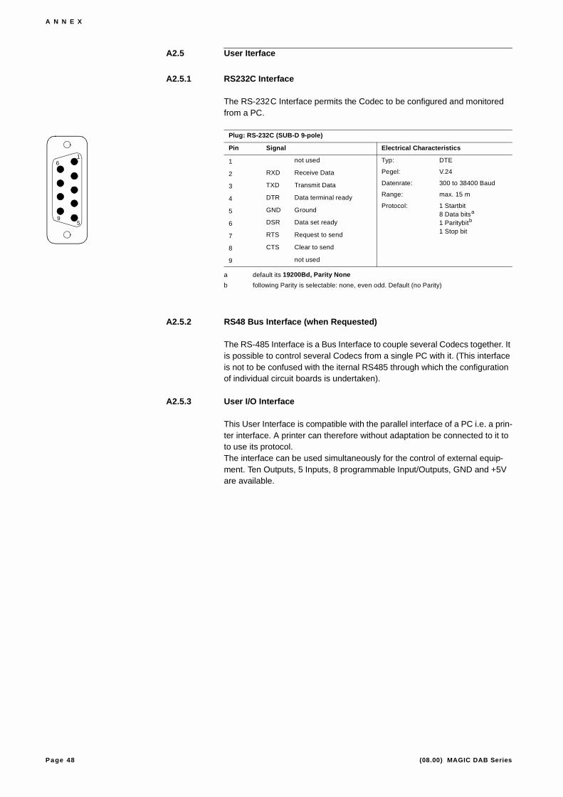
A2.5.1 RS232C Interface
The RS-232C Interface permits the Codec to be configured and monitored from a PC.
A2.5.2 RS48 Bus Interface (when Requested)
The RS-485 Interface is a Bus Interface to couple several Codecs together. It is possible to control several Codecs from a single PC with it. (This interface is not to be confused with the iternal RS485 through which the configuration of individual circuit boards is undertaken).
A2.5.3 User I/O Interface
This User Interface is compatible with the parallel interface of a PC i.e. a prin-ter interface. A printer can therefore without adaptation be connected to it to to use its protocol.The interface can be used simultaneously for the control of external equip-ment. Ten Outputs, 5 Inputs, 8 programmable Input/Outputs, GND and +5V are available.
Plug: RS-232C (SUB-D 9-pole)
Pin Signal Electrical Characteristics
1 not used Typ: DTE
Pegel: V.24
Datenrate: 300 to 38400 Baud
Range: max. 15 m
Protocol: 1 Startbit8 Data bitsa
1 Paritybitb
1 Stop bit
a default its 19200Bd, Parity None
b following Parity is selectable: none, even odd. Default (no Parity)
2 RXD Receive Data
3 TXD Transmit Data
4 DTR Data terminal ready
5 GND Ground
6 DSR Data set ready
7 RTS Request to send
8 CTS Clear to send
9 not used
1
5
6
9

Page 49 (08.00) MAGIC DAB Series
A N N E X
Socket: User I/O (SUB-D 25-pole)
Pin Signal Electrical Characteristics
l1 STROBE Out Level: TTL / CMOS
Load: 20 mA2 DATA 0 Out
3 DATA 1 Out
4 DATA 2 Out
5 DATA 3 Out
6 DATA 4 Out
7 DATA 5 Out
8 DATA 6 Out
9 DATA 7 Out
10 ACK In
11 BUSY In
12 PE In
13 SELECT In
14 FEED XT In / Out
15 ERROR In
16 RESET Out
17 +5V/50 mA Out
18 USER 0 In / Out
19 USER 1 In / Out
20 USER 2 In / Out
21 USER 3 In / Out
22 USER 4 In / Out
23 USER 5 In / Out
24 USER 6 In / Out
25 GND
Remarks: Users 0 to 6 and Feed XT are switchable as Inputs or Outputs
1
13
14
25

Page 50 (08.00) MAGIC DAB Series
A N N E X
Page 51 (08.00) MAGIC DAB Series
A N N E X
A N N E X 3 L I S T O F A L A R M S
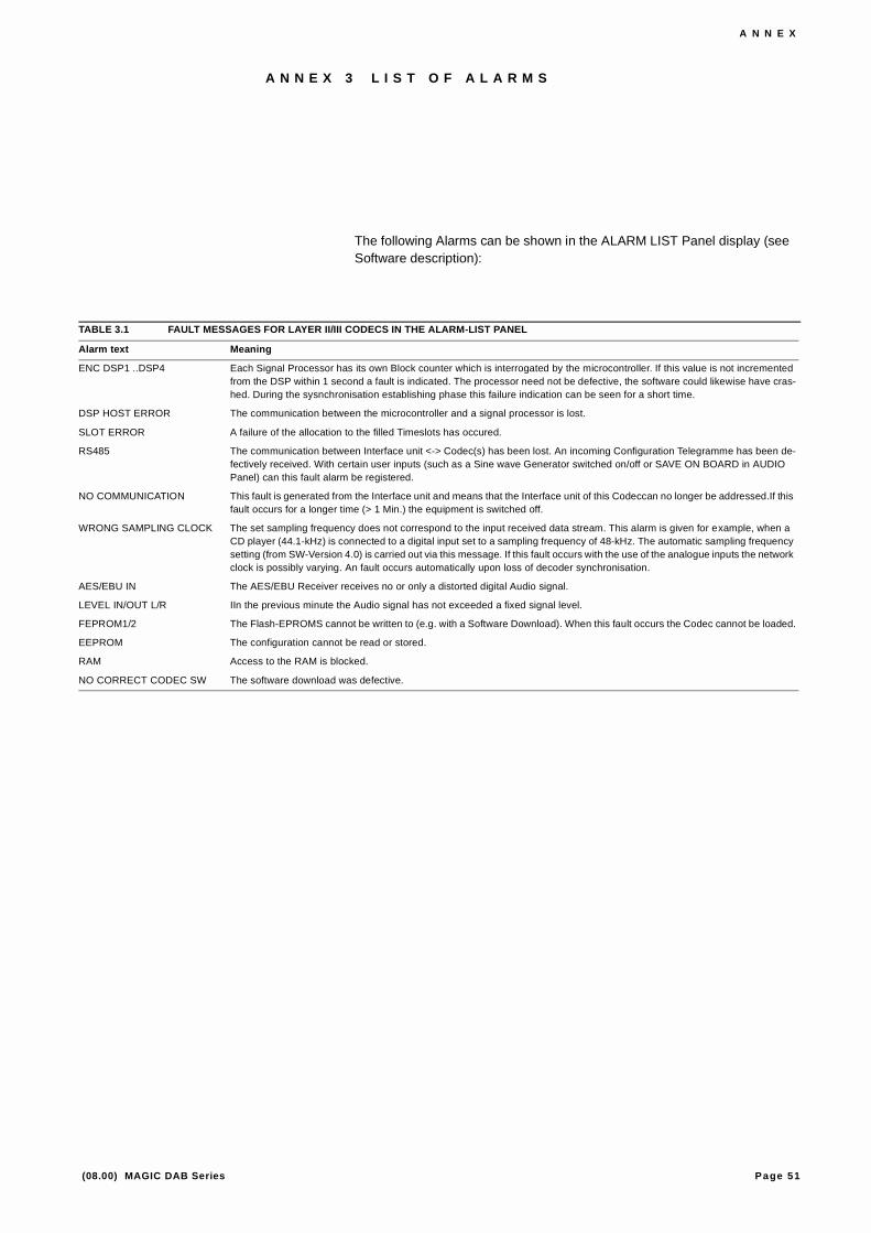
The following Alarms can be shown in the ALARM LIST Panel display (see Software description):
TABLE 3.1 FAULT MESSAGES FOR LAYER II/III CODECS IN THE ALARM-LIST PANEL
Alarm text Meaning
ENC DSP1 ..DSP4 Each Signal Processor has its own Block counter which is interrogated by the microcontroller. If this value is not incremented from the DSP within 1 second a fault is indicated. The processor need not be defective, the software could likewise have cras-hed. During the sysnchronisation establishing phase this failure indication can be seen for a short time.
DSP HOST ERROR The communication between the microcontroller and a signal processor is lost.
SLOT ERROR A failure of the allocation to the filled Timeslots has occured.
RS485 The communication between Interface unit <-> Codec(s) has been lost. An incoming Configuration Telegramme has been de-fectively received. With certain user inputs (such as a Sine wave Generator switched on/off or SAVE ON BOARD in AUDIO Panel) can this fault alarm be registered.
NO COMMUNICATION This fault is generated from the Interface unit and means that the Interface unit of this Codeccan no longer be addressed.If this fault occurs for a longer time (> 1 Min.) the equipment is switched off.
WRONG SAMPLING CLOCK The set sampling frequency does not correspond to the input received data stream. This alarm is given for example, when a CD player (44.1-kHz) is connected to a digital input set to a sampling frequency of 48-kHz. The automatic sampling frequency setting (from SW-Version 4.0) is carried out via this message. If this fault occurs with the use of the analogue inputs the network clock is possibly varying. An fault occurs automatically upon loss of decoder synchronisation.
AES/EBU IN The AES/EBU Receiver receives no or only a distorted digital Audio signal.
LEVEL IN/OUT L/R IIn the previous minute the Audio signal has not exceeded a fixed signal level.
FEPROM1/2 The Flash-EPROMS cannot be written to (e.g. with a Software Download). When this fault occurs the Codec cannot be loaded.
EEPROM The configuration cannot be read or stored.
RAM Access to the RAM is blocked.
NO CORRECT CODEC SW The software download was defective.

Page 52 (08.00) MAGIC DAB Series
A N N E X
I N D E X
Symbols#1...#6 30
Numerics1 ¥ X.21 121920-kbit/s X.21 signal 11253V 193 x So 1232-kHz 1445 H 1948-kHz 146 ¥ X.21 1265 H 196-way J.52 1190V 19
AAddress 22AES/EBU 14ALARM 27, 30Alarm Indication Signal 28Application 19Assembly 7AUDIO 29, 31
BB-CHANNELS 30block diagram 13Byte-synchronisation 11
CConcept 7consumption 19Control File 28, 31CRC4-frame 12
DDAB Source Encode 19Data Network 18DCE 12Defered maintenance alarm ALARM 28Deferred maintenance 11DIL 22DMU ISDN 30Double-Frame 12
DTE 12
EE1 12, 18, 21E1 transmission 11earthing screw 19Encoder Address 22ETS 300401 7ETS 300797 7Extension Bus 24
Ffront view 8
GG.703 Network Interface 21G.711 11G.722 11G.728 11
HHSD 12
IInstallation 17ISO/IEC 11172-3 14ITU-T J.52 7
JJ.52 28, 30jumpers 21
LLAYOUT OF THE JUMPERS 21LED Display 27, 30LED display 7LSD 12
MMains Supply 19measurements 17multiplex 11
NNetwork Interface 17NO CLOCK 28NO COMMunication 29, 31
NO SIGNAL 27NO SYNC 28
Oopen equipment 7operation 17operator 11
PPOWER 27, 30Prompt maintenance 11Prompt maintenance ALARM 28
Rrear view 7Relative Humidity 17RS232 AUX 13RS232C 13RS449 12, 17
SS0 18Sample Rate Converter 14SAMPLing CLocK 29, 31sampling frequencies 14sampling rate converter 14Service Transport Interface 28, 31STI 7surrounding temperature 17switch 22symmetrical 18
TT1 12, 18, 21Timeslot 16 11timeslots 11TS16 12
Uunsymmetrical 18User I/O 12
XX.21 11, 17