
D54: HMI Definition Document - ASAS TN · HMI Definition Document _____ _____ MA-AFAS PROJECT Page...
86
CONTRACT N° : G4RD-2000-00228 PROJECT N° : GRD1-1999-10516 ACRONYM : MA-AFAS THE MORE A UTONOMOUS – A IRCRAFT IN THE F UTURE AIR TRAFFIC MANAGEMENT S YSTEM D54: HMI Definition Document AUTHOR: NLR PROJECT CO-ORDINATOR : BAE SYSTEMS PRINCIPAL CONTRACTORS : Airtel ATN Ltd (Ireland) QINETIQ (UK) ETG (Germany) EUROCONTROL (France) NLR (Netherlands) ASSISTANT CONTRACTORS: Airsys ATM (France) Alenia Difesa (Italy) AMS (Italy) DLR (Germany) FRQ (Austria) Indra Sistemas (Spain) NATS (UK) SCAA (Sweden) SC-TT (Sweden) Skysoft (Portugal) SOFREAVIA (France) Stasys Limited (UK) Report Number: D54 Project Reference number : MA-AFAS – WP2.1 - Date of issue of this report : August, 2002 Issue No: 1.0 PROJECT START DATE : 1/3/2000 DURATION: 36 Months Project funded by the European Community under the ‘Competitive and Sustainable Growth’ Programme (1998-2002)
Transcript of D54: HMI Definition Document - ASAS TN · HMI Definition Document _____ _____ MA-AFAS PROJECT Page...

CONTRACT N° : G4RD-2000-00228
PROJECT N° : GRD1-1999-10516
ACRONYM : MA-AFAS
THE MORE AUTONOMOUS – AIRCRAFT IN THE FUTUREAIR TRAFFIC MANAGEMENT SYSTEM
D54: HMI Definition Document
AUTHOR: NLR
PROJECT CO-ORDINATOR : BAE SYSTEMS
PRINCIPAL CONTRACTORS :Airtel ATN Ltd (Ireland) QINETIQ (UK)ETG (Germany) EUROCONTROL (France)NLR (Netherlands)
ASSISTANT CONTRACTORS:Airsys ATM (France) Alenia Difesa (Italy)AMS (Italy) DLR (Germany)FRQ (Austria) Indra Sistemas (Spain) NATS (UK) SCAA (Sweden)SC-TT (Sweden) Skysoft (Portugal)SOFREAVIA (France) Stasys Limited (UK)
Report Number: D54Project Reference number : MA-AFAS – WP2.1 -Date of issue of this report : August, 2002Issue No: 1.0PROJECT START DATE : 1/3/2000DURATION: 36 Months
Project funded by the European Communityunder the ‘Competitive and SustainableGrowth’ Programme (1998-2002)

HMI Definition Document____________________________________________________________________________________________________________
____________________________________________________________________________________________________________
MA-AFAS PROJECT Page 2 of 86
HMI Definition Document
HMI-DD
WP: 2.1
Rev: 1.0
Date: August 9, 2002
Author Co-Authors/reviewers
NLR – Hans Huisman Nico de Gelder
MA-AFAS partners

HMI Definition Document____________________________________________________________________________________________________________
____________________________________________________________________________________________________________
MA-AFAS PROJECT Page 3 of 86
Table of contents
1. INTRODUCTION................................................................................................................................................... 5
2. GENERAL HMI DESIGN PHILOSOPHY .......................................................................................................... 5
3. FLIGHT DECK LAYOUT..................................................................................................................................... 5
4. CONTROL AND DISPLAY PHILOSOPHY ....................................................................................................... 6
4.1. OPERATING THE MCDU........................................................................................................................................ 64.2. OPERATING THE NAVIGATION DISPLAY ................................................................................................................. 8
4.2.1. Range settings of the PROF display ......................................................................................................... 114.3. OPERATING SOFTKEYS ON THE NAVIGATION DISPLAY .......................................................................................... 214.4. OPERATING THE CURSOR CONTROL DEVICE ....................................................................................................... 254.5. OPERATING THE DISPLAY CONTROL PANEL.......................................................................................................... 25
5. SPECIFIC MA-AFAS FUNCTIONS................................................................................................................... 26
5.1. INTRODUCTION.................................................................................................................................................... 265.2. ASAS IN MAS WITHOUT CPDLC SUPPORT ........................................................................................................ 27
5.2.1. Target selection using the ND................................................................................................................... 275.2.2. Target selection using the MCDU............................................................................................................. 275.2.3. Remain behind using the ND .................................................................................................................... 285.2.4. Remain behind using the MCDU .............................................................................................................. 325.2.5. Merging using the ND............................................................................................................................... 33
5.2.5.1. Merging in detail. .................................................................................................................................................. 365.2.6. Merging using the MCDU......................................................................................................................... 395.2.7. Resume using the ND ................................................................................................................................ 405.2.8. Resume using the MCDU.......................................................................................................................... 425.2.9. Passing using the ND................................................................................................................................ 435.2.10. Passing using the MCDU.......................................................................................................................... 455.2.11. Simplified display concept ........................................................................................................................ 47
5.3. ASAS IN MAS WITH CPDLC SUPPORT............................................................................................................... 485.3.1. Remain behind using the ND (with CPDLC) ............................................................................................ 485.3.2. Remain behind using the MCDU (with CPDLC) ...................................................................................... 495.3.3. Merging using the ND (with CPDLC)....................................................................................................... 495.3.4. Merging using the MCDU (with CPDLC) ................................................................................................ 495.3.5. Resume using the ND (with CPDLC)........................................................................................................ 495.3.6. Resume using the MCDU (with CPDLC).................................................................................................. 505.3.7. Passing using the ND (with CPDLC)........................................................................................................ 505.3.8. Passing using the MCDU (with CPDLC).................................................................................................. 50
5.4. ASAS IN FFAS ................................................................................................................................................... 515.4.1. Activating Autonomous Operation functionality....................................................................................... 515.4.2. Types of conflicts in FFAS ........................................................................................................................ 535.4.3. Conflicts detected above the threshold time (priority rules) ..................................................................... 545.4.4. Conflicts detected below the threshold time (co-operative rules) ............................................................. 54
5.5. TAXI MANAGEMENT ............................................................................................................................................ 545.5.1. Display elements to display on the taxi map............................................................................................. 545.5.2. Taxi without CPDLC support.................................................................................................................... 555.5.3. Taxi with CPDLC support......................................................................................................................... 555.5.4. Taxi with CPDLC on the MCDU. ............................................................................................................. 56
5.6. PRECISION APPROACH AND LANDING................................................................................................................... 565.6.1. SBAS ......................................................................................................................................................... 565.6.2. GBAS......................................................................................................................................................... 56
5.7. CPDLC (INCLUDING 4DTN) ............................................................................................................................... 565.7.1. CPDLC using the ND................................................................................................................................ 57
5.7.1.1. Specific CPDLC messages. ................................................................................................................................... 58

HMI Definition Document____________________________________________________________________________________________________________
____________________________________________________________________________________________________________
MA-AFAS PROJECT Page 4 of 86
5.7.2. CPDLC using the MCDU.......................................................................................................................... 585.7.2.1. Handling standard messages.................................................................................................................................. 585.7.2.2. Long uplink messages............................................................................................................................................ 615.7.2.3. More than one uplink message in queue................................................................................................................ 625.7.2.4. Concatenated messages ......................................................................................................................................... 645.7.2.5. Responding to uplinks requiring pilot or system data ........................................................................................... 645.7.2.6. Responding to uplinks requiring event based response ......................................................................................... 66
5.8. GRAPHICAL ROUTE EDITING................................................................................................................................. 675.9. REVIEW OF FLIGHT PLAN MODIFICATIONS ............................................................................................................ 685.10. COMMUNICATION WITH AIRLINE OPERATION CENTRE (AOC)........................................................................ 68
5.10.1. Flight plan page........................................................................................................................................ 695.10.2. Load sheet page ........................................................................................................................................ 705.10.3. Departure slot page .................................................................................................................................. 715.10.4. Meteo pages .............................................................................................................................................. 715.10.5. Free text pages.......................................................................................................................................... 73
5.11. FLIGHT INFORMATION SERVICES (FIS) ........................................................................................................... 74
6. AUTO FLIGHT MODES OF OPERATION...................................................................................................... 75
6.1. FLIGHT MODE ANNUNCIATION IN GENERAL......................................................................................................... 756.2. FLIGHT MODES FOR MA-AFAS ........................................................................................................................... 77
7. ALERTING............................................................................................................................................................ 80
ABBREVIATIONS......................................................................................................................................................... 83

HMI Definition Document____________________________________________________________________________________________________________
____________________________________________________________________________________________________________
MA-AFAS PROJECT Page 5 of 86
1. IntroductionThis document describes the HMI design based on the <<CMC FMS>>. For describing the functionality anoperations manual like way is used. In other words the functions are described in a way the user will beconfronted with them and the underlying system functionality can be found in related MA-AFASdocumentation.
2. General HMI Design philosophyA baseline FMS including MCDU definition is adopted from CMC in a Boeing environment. In addition tothis baseline, the following objectives are stated:• Pilots shall make decisions and initiate changes• Information shall make the pilot aware• Pilots shall have authority over automated systems• Workload shall be low, in particular in TMA operation• Information shall aid pilots in error detection• Information shall be relevant , prevent distraction and easily understood• Controls shall be functionally grouped• Design shall reduce head down time• Simplicity shall reduce training times and flight crew error• Information shall aid pilots in dispatch decisions
3. Flight deck layout
Figure 3-1 MA-AFAS relevant flight deck items
MA-AFAS is an FMS based project which uses a base line FMS and MA-AFAS functions can be regardedas add-ons to this base line. Flight deck elements which are concerned are the normal FMS relatedinstruments: Multi Function Control and Display Unit (MCDU) , Navigation Display (ND), EFIS controlpanel or Display Control Panel (DCP) and Auto Pilot control panel, or Mode Control Panel (MCP) with inaddition a Cursor Control Device (CCD) for graphical interaction with the ND. Alert lights on theglareshield will be used for incoming data link messages.
MCP &DCP
ND
MCDU
CCD
D/L alert light

HMI Definition Document____________________________________________________________________________________________________________
____________________________________________________________________________________________________________
MA-AFAS PROJECT Page 6 of 86
4. Control and display philosophy
4.1. Operating the MCDU
The MCDU consists of a colour text display of 14 lines of 24 characters, alphanumerical keys, functionkeys, page navigation keys, line select keys and indication lights.Only a high level description is included here and some MA-AFAS specific elements in more detail since abase line FMS design is used.
The colours used for texts on the MCDU display are:Amber Alert messagesCyan Page titles, prompts and inactive route infoGreen Fixed data fields, field titles and waypoint namesMagenta Active TO waypointYellow Prompt (Erase function only)White Computed data, data units, scratchpad data, advisoriesInverted video Active waypoint, modified route indication, highlighting
Three different font sizes are used:Large Manual entries, waypoint info from nav data base, page titles, prompts,
scratchpad data, alert messagesMedium Computed or generated dataSmall Data field units, field titles, fixed data fields
General use of the MCDU display area: PAGE TITLE 1/1
DATA FIELDSELECTABLE DATA FIELD
< ACTION
�OTHER PAGEScratchpad
Special characters:---- Optional data entry���� Mandatory data entry/ Separation character**** Value exceeds its limit<blank> Data is not yet calculated

HMI Definition Document____________________________________________________________________________________________________________
____________________________________________________________________________________________________________
MA-AFAS PROJECT Page 7 of 86
Dedicated function keys:Base line FMS functions will not be explained in this document.MA-AFAS specific functions keys are ATC and ASAS.
INIT/REFGiving access to a number of base line FMS functions (which will not be described here) as well ascommunication with Airline Operation Centre (AOC) and, if applicable, Flight Information Service (FIS)functions.
ATCGiving access to the page for communication with ATC using CPDLC messages.In case an uplink is available, the uplink page is presented, otherwise the downlink page will be presented.More details can be found in section 5.7: “4D trajectory negotiation and CPDLC”.
ASASGiving access to the page for ASAS functions. ASAS functions covered on these MCDU pages concernAutonomous Operation functions and Delegated ASAS function. Delegated ASAS functions with data linksupport will be covered in the ATC function and will be treated as any ATC CPDLC message.

HMI Definition Document____________________________________________________________________________________________________________
____________________________________________________________________________________________________________
MA-AFAS PROJECT Page 8 of 86
ASAS 1/1 AUTO-OPS OFF
1L < SEL 1R
TARGET CODE2L ����� 2R
3L 3R
4L 4R
5L 5R
6L 6R
When target code (i.e. BICCA) is entered and 2L pressed the delegated ASAS functions become available:ASAS 1/1
AUTO-OPS OFF1L < SEL 1R
TARGET CODE2L EH7G8 REMAIN� 2R
SK1833L B737 MERGE� 3R
4L 4R
5L PASS� 5R
6L RESUME� 6R
Note: the order in which the functions are listed should ideally be in order of frequency of use.More detailed descriptions of the ASAS functions can be found in chapter 5.
4.2. Operating the Navigation Display
The ND has the following modes: APP, MAP, PLAN, PROF, TAXI-MAP, TAXI-PLAN and TAXI-ARPT.
First the overall display modes are presented followed by a table containing all available display elements.The usable display area is a square of 6.0 inch by 6.0 inch.

HMI Definition Document____________________________________________________________________________________________________________
____________________________________________________________________________________________________________
MA-AFAS PROJECT Page 9 of 86
General navigation display area use.
Display area for pilot selected display mode.
↑||
5.5“
||↓
Text line area 0.2”Softkeys area
0.3”
← - - - - - 6” - - - - - →
Figure 4-1 Navigation display areas
The display area does not cover the “text line” and “softkeys” areas when those are cancelled. In case theyare presented, the text line and softkeys line are functionally separated from the display size. The displaysymbology does not resize depending on the presentation of the text and keys.
MAP MODEMAP mode is a magnetic heading up mode with a circle segment of 90 degrees (expanded mode) or 360degrees (centre mode).
Figure 4-2 Map mode of the ND (without and with traffic)

HMI Definition Document____________________________________________________________________________________________________________
____________________________________________________________________________________________________________
MA-AFAS PROJECT Page 10 of 86
Figure 4-3 Centered MAP mode
PLAN MODEPLAN mode is a magnetic north up mode with a selected waypoint (by default the active waypoint) in thecentre of a 360 degrees rose (no expanded mode available in plan mode).
Figure 4-4 PLAN mode

HMI Definition Document____________________________________________________________________________________________________________
____________________________________________________________________________________________________________
MA-AFAS PROJECT Page 11 of 86
PROF MODE
Figure 4-5 Profile mode of the ND
PROF display presents the vertical profile of the route with on the left the altitude scale, horizontally thetime scale along the planned route (in case no active flight plan available the time along the current trackdirection is used). On the right a vertical speed scale is presented which is the resultant of the altitude andtime axis.The PROF display is presented in the lower area of the ND usable area. Scaling is such that the entireinformation content of the MAP display is still presented.
4.2.1. Range settings of the PROF displayThe PROF display has three axis which are not independent. When two are defined, the third follows fromit. Since the settings can create a highly illogical picture an automatic ranging is available. This automaticranging is related to the range setting of the MAP/PLAN mode.
The mechanism is as follows, using the horizontal range in Nm of the MAP/PLAN as input:Full altitude scale = 300ft * horizontal range (for ranges larger than 40 Nm)Time scale = 1.2 min * (horizontal range/4Nm) (for IAS < 252.25 knots)Time scale = 1.2 min * (horizontal range/8Nm) (for IAS >= 252.25 knots)V/S scale = Altitude scale/Time scale
Full altitude scale is 2400ft, 4800ft and 6000ft for respectively 10, 20 and 40Nm range. The time scale has aminimum of 6 minutes and maximum of 24 minutes.For manual settings, the pilot can select the altitude scale and the time scale. The V/S scale results fromthose.
TAXI MAP MODETAXI map mode is comparable with the normal MAP mode: it is heading up oriented using a segment of 90degrees.
HMI Definition Document____________________________________________________________________________________________________________
____________________________________________________________________________________________________________
MA-AFAS PROJECT Page 12 of 86
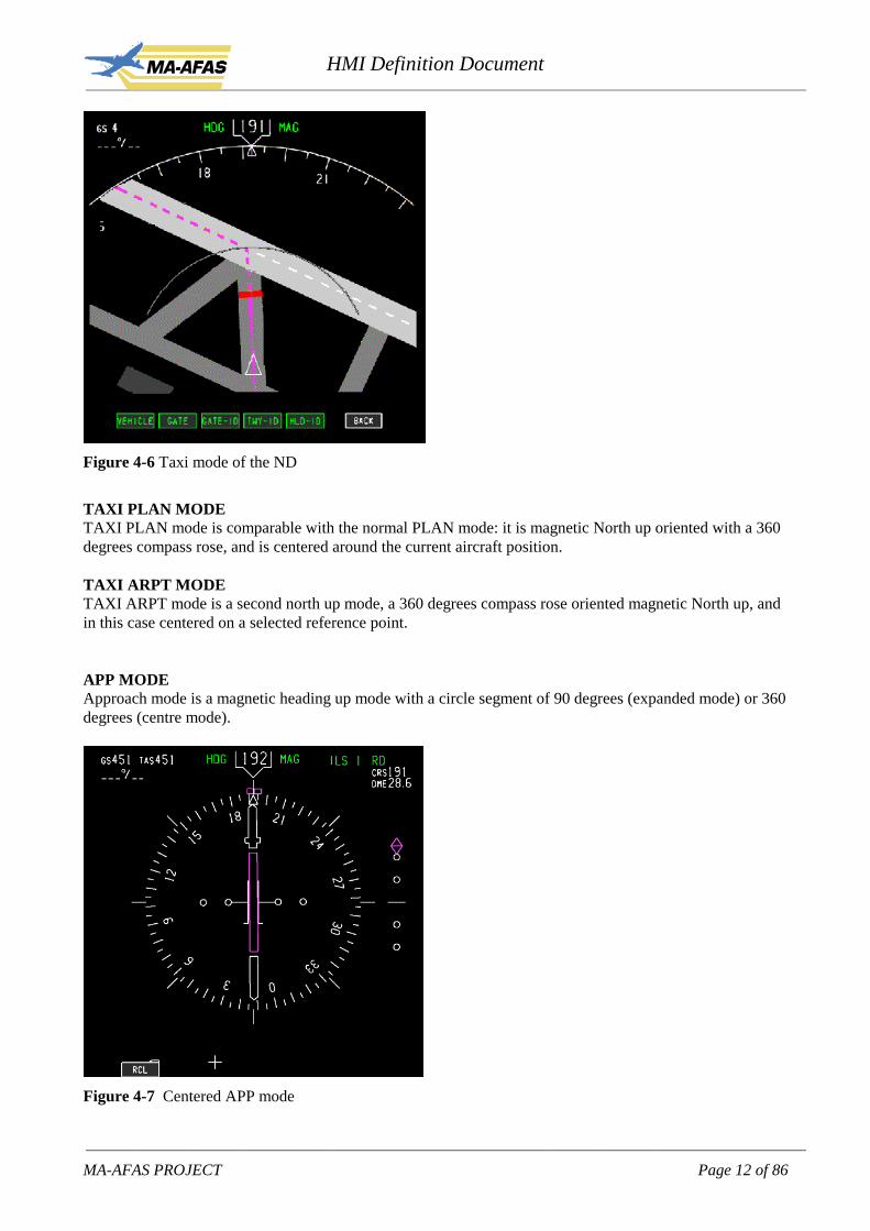
Figure 4-6 Taxi mode of the ND
TAXI PLAN MODETAXI PLAN mode is comparable with the normal PLAN mode: it is magnetic North up oriented with a 360degrees compass rose, and is centered around the current aircraft position.
TAXI ARPT MODETAXI ARPT mode is a second north up mode, a 360 degrees compass rose oriented magnetic North up, andin this case centered on a selected reference point.
APP MODEApproach mode is a magnetic heading up mode with a circle segment of 90 degrees (expanded mode) or 360degrees (centre mode).
Figure 4-7 Centered APP mode

HMI Definition Document____________________________________________________________________________________________________________
____________________________________________________________________________________________________________
MA-AFAS PROJECT Page 13 of 86
Colour convention used:Green (G) Dynamic conditionsWhite (W) Present status, range scalesMagenta (M) Command info, pointers, symbols, fly-to conditionRed (R) WarningsAmber (A) Cautions, faults, flagsCyan (C) Non active or background infoYellow (Y)Grey/White Buttons selectable, function not activeGrey/grey Buttons not selectableGrey/green Buttons selectable, function activeGrey/cyan Buttons selectable, function not active because not all parameters specifiedBlack (B) Blank area, off conditionLight Grey (l-GR)Dark Green (d-G)Grey (GR)
ND symbols and elements explained:Name Symbol Applicable in mode RemarksHeading rose (W)Current heading (W)Heading pointer (W)Display orientation (G)Heading reference (G)
MAPTAXI-MAPAPP
StandardText font height: 4mmNum font height: 6mmin box, 4mm on rose
Selected headingindicator (M)
MAPPLANAPP
Standard.
Selected heading line(M)
MAPPLANAPP
Standard.Line appears when pilotselects new HDG, linedisappears after 10 sec.
Own aircraft symbol (W) MAPPLANTAXI-MAPTAXI-PLANTAXI-ARPT
StandardSize: 10x8 mm
Own aircraft symbol (W) PROF Position:low during climb (0%)mid during cruise (50%)hi during descent (100%)with a smooth transitionfrom one position to the

HMI Definition Document____________________________________________________________________________________________________________
____________________________________________________________________________________________________________
MA-AFAS PROJECT Page 14 of 86
Name Symbol Applicable in mode RemarksotherSize: 6x11 mm
Trend vector (W) MAP Standard, only visiblewhen turning
Range rings (W) MAPAPPTAXI-MAPTAXI-PLAN
3 rings for MAP andAPP, 1 ring for TAXI,the middle shows asingle value of 50% ofthe currently selectedrange. Rotated font, fontheight: 4.5mm.
Active waypoint info (Mand W)
MAPPLANPROF
StandardFont height: 4.5mm
Ground speed/ Trueairspeed indications (W)
MAPPLANPROFTAXI-MAPTAXI-PLANTAXI-ARPT
StandardText font height: 3.5mmNum font height: 4.5mm(No TAS presented ontaxi modes)
Waypoints (active route)Active (M)Not active (W)
MAPPLAN
StandardSymbol size: 7x7 mmTxt font height: 3.5mmNon scalable
Not active waypoints areall other waypoints onactive route, either beingmodified or not.
Waypoints (inactiveroute) (C)
MAPPLAN
StandardSymbol size: 7x7 mmTxt font height: 3.5mmNon scalable
Waypoints (active route)Active (M)not active (W)
PROF Symbol and colourcoding identical as inMAP and PLAN.

HMI Definition Document____________________________________________________________________________________________________________
____________________________________________________________________________________________________________
MA-AFAS PROJECT Page 15 of 86
Name Symbol Applicable in mode RemarksWaypoints (not part ofFMS routes) (C)
MAPPLAN
StandardSymbol size: 4x4 mmTxt font height: 3.5mmNon scalable
Navaids VOR (C) MAPPLAN
StandardSymbol size: 4x4 mmTxt font height: 3.5mmNon scalable
Navaids DME (C) MAPPLAN
StandardSymbol size: 7x7 mmTxt font height: 3.5mmNon scalable
Navaids VOR/DME (C) MAPPLAN
StandardSymbol size: 7x7 mmTxt font height: 3.5mmNon scalable
Navaids NDB (C) MAPPLAN
StandardSymbol size: 7x7 mmTxt font height: 3.5mmNon scalable
Airport (C) MAPPLAN
StandardSymbol size: 5x5 mmTxt font height: 3.5mmNon scalable
Vertical profile points(G)
MAPPLAN
StandardSymbol size: 5x5 mmTxt font height: 3.5mmNon scalable
Indicates map position of“T/C” (Top of Climb),“T/D” (Top of Descent),“S/C” (Step Climb),“E/D” (End of Descent).Indicates intermediateT/D points duringdescent, level segmentaltitude is displayed“T/D-4000”
Indicates start ofdeceleration to holdingpattern speed, wpt speedrestriction, or flaps upmanoeuvring speed“DECEL”
Indicates start ofdeceleration for airportspeed restriction, no text

HMI Definition Document____________________________________________________________________________________________________________
____________________________________________________________________________________________________________
MA-AFAS PROJECT Page 16 of 86
Name Symbol Applicable in mode Remarkslabel only green circle.
Active route (M)Modified route (W)
MAPPLAN
Standard.Magenta continuous lineconnecting whitewaypoints. Activewaypoint is magenta.Modified part of theactive route is displayedby white short dashesbetween white waypoints
Active route (M) PROF Symbol and colourcoding identical as inMAP and PLAN
Active route data (M andW)
MAPPLAN
StandardWhen DATA optionselectedMagenta for activewaypoint, white for notactive waypoint
Inactive route (C) MAPPLAN
Standard.Cyan long dashesconnecting cyanwaypoints
Offset route (M) MAPPLAN
Standard.Magenta dot-dash lineparallel to the activeroute
HMI Definition Document____________________________________________________________________________________________________________
____________________________________________________________________________________________________________
MA-AFAS PROJECT Page 17 of 86
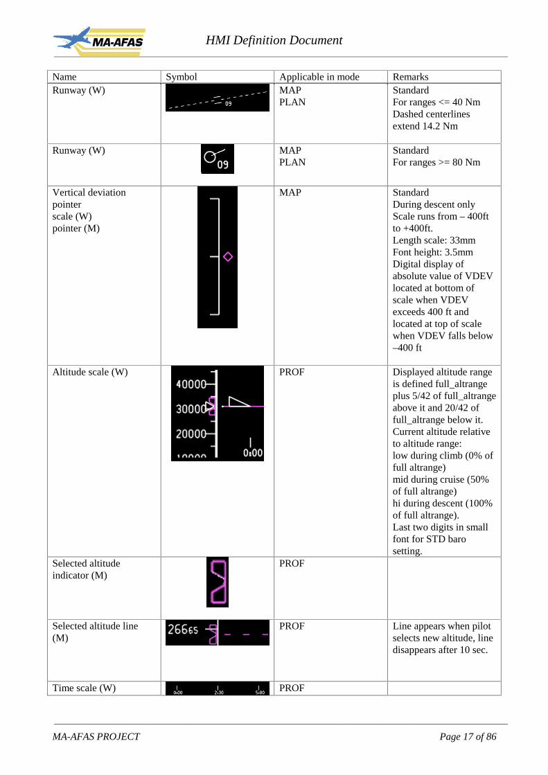
Name Symbol Applicable in mode RemarksRunway (W) MAP
PLANStandardFor ranges <= 40 NmDashed centerlinesextend 14.2 Nm
Runway (W) MAPPLAN
StandardFor ranges >= 80 Nm
Vertical deviationpointerscale (W)pointer (M)
MAP StandardDuring descent onlyScale runs from – 400ftto +400ft.Length scale: 33mmFont height: 3.5mmDigital display ofabsolute value of VDEVlocated at bottom ofscale when VDEVexceeds 400 ft andlocated at top of scalewhen VDEV falls below–400 ft
Altitude scale (W) PROF Displayed altitude rangeis defined full_altrangeplus 5/42 of full_altrangeabove it and 20/42 offull_altrange below it.Current altitude relativeto altitude range:low during climb (0% offull altrange)mid during cruise (50%of full altrange)hi during descent (100%of full altrange).Last two digits in smallfont for STD barosetting.
Selected altitudeindicator (M)
PROF
Selected altitude line(M)
PROF Line appears when pilotselects new altitude, linedisappears after 10 sec.
Time scale (W) PROF

HMI Definition Document____________________________________________________________________________________________________________
____________________________________________________________________________________________________________
MA-AFAS PROJECT Page 18 of 86
Name Symbol Applicable in mode Remarks
Range setting for PROFmode
PROF Auto scaling is linkedwith MAP and PLANrange setting. Manualleaves both altitude andtime scale pilotadjustable.
Vertical speed scale (W) PROF Vertical speed scale isthe resultant from thealtitude and time scalesetting. In auto scalingmode always full scale500fpm or 1000 fpmdepending on en-route orTMA flight phase.
Actual V/S (W) PROF Diamond symbol on V/Sscale
Selected V/S indicator(M)
PROF Magenta circle on V/Sscale.
Selected V/S line (M) PROF Line appears when pilotselects new V/S, linedisappears after 10 sec.Line connects fixed a/csymbol with selectedV/S symbol.
Aircraft (W) MAPPLANTAXI-MAPTAXI-PLANTAXI-ARPTAPP
Symbol is oriented inaircraft track. Labelcontains relative altitude,flight identification(callsign and BICCAcode) and indicatedairspeed. (switching anddecluttering avail)Symbol size: 4.5x6mmFont height: 2.5mmNon scalable
Climb/descent arrow fortraffic (W)
MAPPLANAPP
If aircraft V/S exceeds500ft/min, arrow ispresented. Up or down.
Menu buttons (W, G, C) MAPPLANAPPTAXI-MAPTAXI-PLANTAXI-ARPT
Bottom of screen belowaircraft symbol. Buttonsare multi functional.Button size: 17 x8 mmFont height: 3.5 mmText centered in knob
Text line (G) MAP Between button and

HMI Definition Document____________________________________________________________________________________________________________
____________________________________________________________________________________________________________
MA-AFAS PROJECT Page 19 of 86
Name Symbol Applicable in mode RemarksPLANAPPTAXI-MAPTAXI-PLANTAXI-ARPT
fixed aircraft symbol.Font height: 3.5 mmMax 50 characters intextline. If applicable,present scroll keys andmsg queue number.
Taxiway (GR) TAXI-MAPTAXI-PLANTAXI-ARPT
Taxiway ident (Y) TAXI-MAPTAXI-PLANTAXI-ARPT
Runway (l-GR) TAXI-MAPTAXI-PLANTAXI-ARPT
Runway ident (Y) TAXI-MAPTAXI-PLANTAXI-ARPT
Stopbar (R) TAXI-MAPTAXI-PLANTAXI-ARPT
only active stopbarspresented
Holding position ident(R, W)
TAXI-MAPTAXI-PLANTAXI-ARPT
Intersection of taxiways(GR)
TAXI-MAPTAXI-PLANTAXI-ARPT
Intersection of taxiways/runways (GR, l-GR)
TAXI-MAPTAXI-PLANTAXI-ARPT
Apron (GR) TAXI-MAPTAXI-PLANTAXI-ARPT
Parking or stand(small / large range)(W, M)
/
/
TAXI-MAPTAXI-PLANTAXI-ARPT
Symbol to use dependson selected displayrange, white standardmagenta is cleared
Stand guidance lines(W, M)
TAXI-MAPTAXI-PLANTAXI-ARPT
white standard, magentais cleared
Parking ident (C) TAXI-MAPTAXI-PLANTAXI-ARPT
Building (GR) TAXI-MAP
HMI Definition Document____________________________________________________________________________________________________________
____________________________________________________________________________________________________________
MA-AFAS PROJECT Page 20 of 86
Name Symbol Applicable in mode RemarksTAXI-PLANTAXI-ARPT
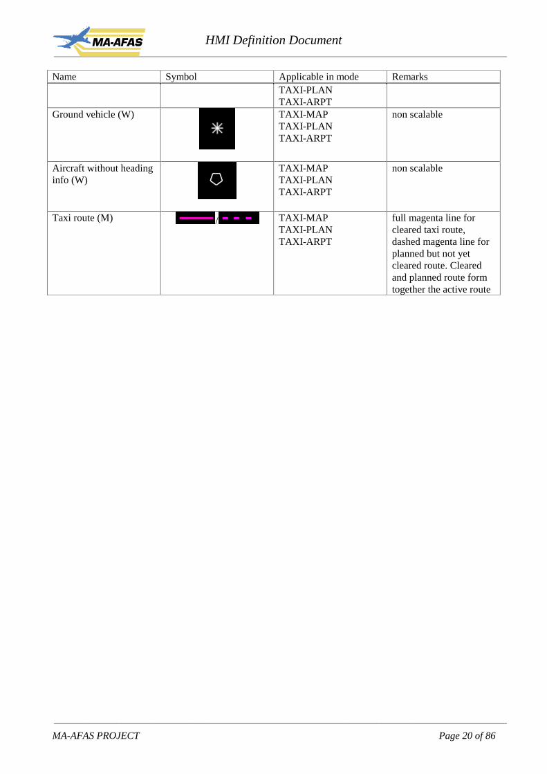
Ground vehicle (W) TAXI-MAPTAXI-PLANTAXI-ARPT
non scalable
Aircraft without headinginfo (W)
TAXI-MAPTAXI-PLANTAXI-ARPT
non scalable
Taxi route (M) / TAXI-MAPTAXI-PLANTAXI-ARPT
full magenta line forcleared taxi route,dashed magenta line forplanned but not yetcleared route. Clearedand planned route formtogether the active route

HMI Definition Document____________________________________________________________________________________________________________
____________________________________________________________________________________________________________
MA-AFAS PROJECT Page 21 of 86
Labels near traffic symbols:
Setting (independent selectable inmenu, see next section)
Presentation
Barometric altitude (relative in hundredfeet)
Arrow up or down for climb/descentindication. Appears when absolutevertical speed of traffic > 500ft/min.
BICCA code
Indicated airspeed or Mach (dependingon whether target speed of the targetaircraft is IAS or Mach, default IAS)
Callsign or flight identification
All above
Individual aircraft data control
Note: both the code and callsign are included for different purposes. The code is used for identifying anaircraft which is part of an ATC clearance either via R/T or data link. The callsign is used for improvingsituation awareness especially in an R/T situation. The partyline effect is enhanced with a CDTI whichincludes callsigns. A second reason why to include a callsign and not only the code is that a callsign is easierto remember and communicate between PF and PNF than a 5 digit code.
4.3. Operating softkeys on the navigation display
At the bottom of the screen a number of softkeys can be presented which are to be operated using the CCD.The following tree structure is used for the softkeys.Level 0 means that the menu keys are not presented, only the recall button is presented in the most left-handbutton position.

HMI Definition Document____________________________________________________________________________________________________________
____________________________________________________________________________________________________________
MA-AFAS PROJECT Page 22 of 86
Each cell is filled with the function of the button followed by a number. This number represents whichbutton is used. There are six buttons, in one line, available at the bottom of the ND. For on/off selection thedefault value is “off” unless indicated otherwise.
Level 1 Level 2 Level 3 Level 4 resulting action
OPTION1 FID1 flight id (callsign) on/off for all aircraft(MAP) STA2 stations/beacons on/off(PLAN) WPT3 waypoints on/off
ARPT4 airports on/off, default onDATA5 constraints & ETA on/offBACK6 back to level 1
OPTION1 VEHICLE1 ground vehicles on/off(TAXI) GATE2 gate on/off
GATE ID3 gate identifiers on/offTWY ID4 taxi way on/offHOLD ID5 holding identifiers on/offBACK6 back to level 1
OPTION1 FID1 flight id (callsign) on/off for all aircraft(APP) BACK6 back to level 1
ATC2*) a
WILCO1 Downlinks wilco message **)
STBY2 Downlinks standby message***)UNABLE3 Downlinks unable message **)LOAD4 EXEC1 Activate manoeuvre
ERASE5 Erase manoeuvreBACK6 back to level 2
NEXT5 present next message if more than onemessage received
CLEAR1 clears message (avail upon reply downlinked)BACK6 back to level 1
ATC2 *) b
AFFIRM1 downlinks affirm message **)
STBY2 downlinks standby message***)NEG3 downlinks negative message **)LOAD4 EXEC1 Activate manoeuvre
ERASE5 Erase manoeuvreBACK6 back to level 2
NEXT5 present next message if more than onemessage received
CLEAR1 clears message (avail upon reply downlinked)BACK6 back to level 1
ATC2*) c
ROGER1 downlinks wilco message **)
STBY2 downlinks standby message***)UNABLE3 downlinks unable message **)LOAD4 EXEC1 Activate manoeuvre
ERASE5 Erase manoeuvreBACK6 back to level 2
HMI Definition Document____________________________________________________________________________________________________________
____________________________________________________________________________________________________________
MA-AFAS PROJECT Page 23 of 86
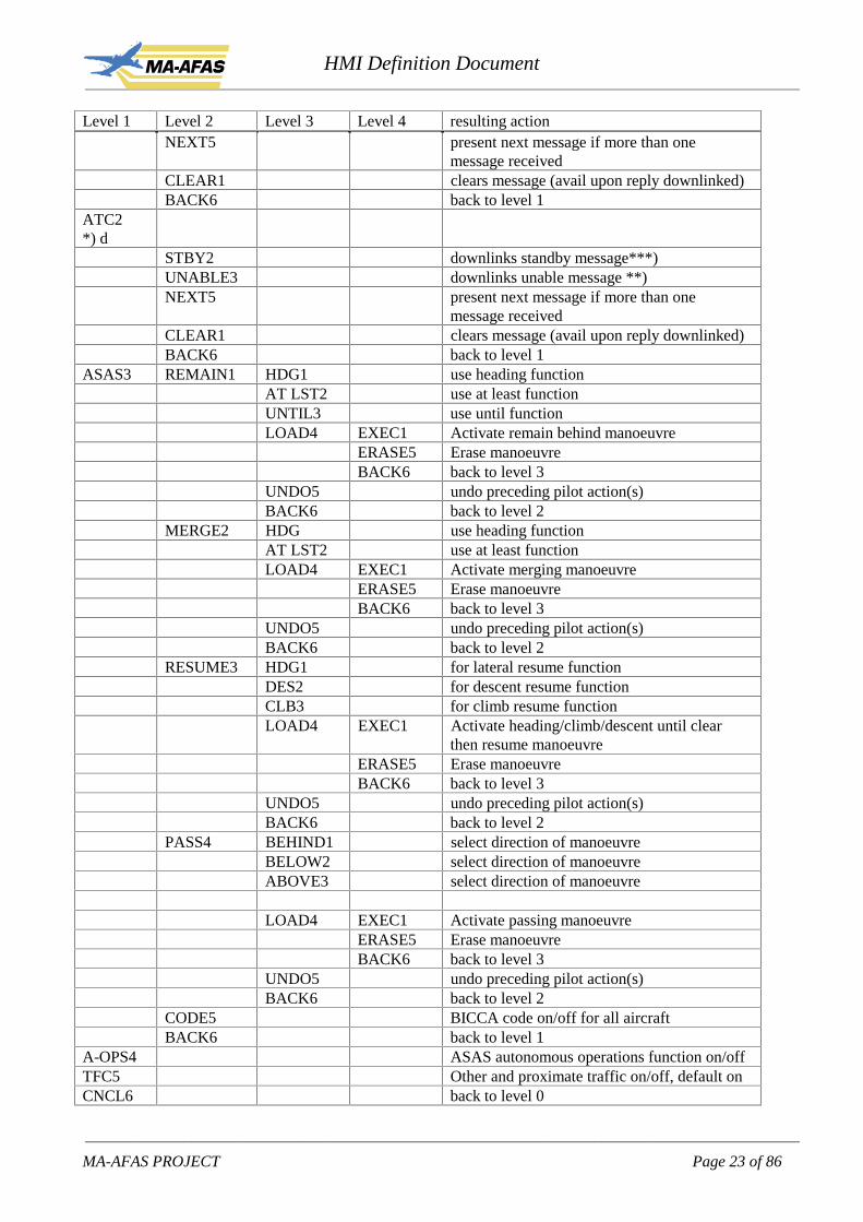
Level 1 Level 2 Level 3 Level 4 resulting actionNEXT5 present next message if more than one
message receivedCLEAR1 clears message (avail upon reply downlinked)BACK6 back to level 1
ATC2*) d
STBY2 downlinks standby message***)UNABLE3 downlinks unable message **)NEXT5 present next message if more than one
message receivedCLEAR1 clears message (avail upon reply downlinked)BACK6 back to level 1
ASAS3 REMAIN1 HDG1 use heading functionAT LST2 use at least functionUNTIL3 use until functionLOAD4 EXEC1 Activate remain behind manoeuvre
ERASE5 Erase manoeuvreBACK6 back to level 3
UNDO5 undo preceding pilot action(s)BACK6 back to level 2
MERGE2 HDG use heading functionAT LST2 use at least functionLOAD4 EXEC1 Activate merging manoeuvre
ERASE5 Erase manoeuvreBACK6 back to level 3
UNDO5 undo preceding pilot action(s)BACK6 back to level 2
RESUME3 HDG1 for lateral resume functionDES2 for descent resume functionCLB3 for climb resume functionLOAD4 EXEC1 Activate heading/climb/descent until clear
then resume manoeuvreERASE5 Erase manoeuvreBACK6 back to level 3
UNDO5 undo preceding pilot action(s)BACK6 back to level 2
PASS4 BEHIND1 select direction of manoeuvreBELOW2 select direction of manoeuvreABOVE3 select direction of manoeuvre
LOAD4 EXEC1 Activate passing manoeuvreERASE5 Erase manoeuvreBACK6 back to level 3
UNDO5 undo preceding pilot action(s)BACK6 back to level 2
CODE5 BICCA code on/off for all aircraftBACK6 back to level 1
A-OPS4 ASAS autonomous operations function on/offTFC5 Other and proximate traffic on/off, default onCNCL6 back to level 0

HMI Definition Document____________________________________________________________________________________________________________
____________________________________________________________________________________________________________
MA-AFAS PROJECT Page 24 of 86
Level 1 Level 2 Level 3 Level 4 resulting action
L-PASS3 HDG1 for lateral resume functionBEHIND2 select direction of manoeuvreLOAD4 EXEC1 Activate heading/climb/descent until clear
then resume manoeuvreERASE5 Erase manoeuvreBACK6 back to level 3
UNDO5 undo preceding pilot action(s)BACK6 back to level 2
V-PASS4 LEVEL1 for climb/descent resume functionBELOW2 select direction of manoeuvreABOVE3 select direction of manoeuvre
LOAD4 EXEC1 Activate passing manoeuvreERASE5 Erase manoeuvreBACK6 back to level 3
UNDO5 undo preceding pilot action(s)BACK6 back to level 2
*) The ATC menu items depend on the uplinked message, a,b,c and d are indicating this difference. TheATC menu as part of the overall softkey menus is questioned due to the anticipated need for direct access atleast for time critical messages and the unacceptability to automatically interrupt other tasks upon receipt ofATC messages.**)Each message has its own responses defined: WILCO – UNABLE or AFFIRM – NEGATIVE orROGER – UNABLE.***)STANDBY is always available, but can only be used once, so after pressing it, the key will change intoits ‘not selectable’ state.
LOADThe load command is used to load the instruction into the FMS modified flighplan, meaning that the FMSwill copy the active flightplan into the modified flightplan and subsequently adds the instruction. Therewithcancelling a possible pilot edit action.EXECThe exec command executes the modified flighplan which is now the active flightplanERASEThe erase command erases the modified flightplan.UNDOThe undo command cancels a data entry (which is not yet included in the modified flightplan)
The shape of the keys:Key type ShapeEntry to deeper menu layer
Function selection at lowest level
The colour coding of the keys:

HMI Definition Document____________________________________________________________________________________________________________
____________________________________________________________________________________________________________
MA-AFAS PROJECT Page 25 of 86
Button txt colour Button colour Appearance Button modeWhite White Selectable and: mode not active or selection OFF
Green Green Selectable and: mode active or selection ON
White Cyan Selectable and: mode not active because not allparameters specified
Dark Grey Dark Grey Not active, not selectable
For example the main menu layer:
After pressing the OPTION key in the MAP or PLAN display mode:
4.4. Operating the Cursor Control Device
The CCD will be a trackball, one for each pilot, positioned aft the MCDU in close reach of the pilot. TheCCD will be equipped with two select buttons. The left one for selecting items on the ND while the rightone is used to display detailed information, if available, on the object selected by the cursor. In addition arotary dial is used for dialling in values or selecting an item from a list. In case no rotary dial is available,which is highly undesirable, the entry of numerical values -and possibly also identifiers- in the text line onthe ND is performed thru the MCDU keyboard. If the state of the text line selection is such that the nextrequired entry is a value or identifier then MCDU scratchpad selections will be directly copied into the textline.
The cursor is displayed as a white crosshair, a non-directional symbol of 6 by 6 mm.
.
4.5. Operating the display control panel
The display control panel (DCP) is used to make the most frequently and time critical display selections.These DCP selections can be made in parallel with display control functions covered by the menu of softbuttons on the ND.
DCP controls:Rotary dial 6 positions(double legend, orselected value in displaynext to button)
Range Nm air / taxi:• 10 / 0.25• 20 / 0.5• 40 / 1.0

HMI Definition Document____________________________________________________________________________________________________________
____________________________________________________________________________________________________________
MA-AFAS PROJECT Page 26 of 86
(BAC 1-11: 6 avail)(ATTAS: avail)
• 80 / 2.0• 160 / 4.0• 320
Rotary dial 4 positions(BAC 1-11: 3 avail)(ATTAS:)
Mode:• MAP• TAXI*)• PROF• APP **)
2 Select buttons(BAC 1-11: 4 avail)(ATTAS: avail)
• PLAN (toggle between monitoring mode andplanning mode)
• CTR (toggle between 90 deg and 360 deg of rosesegment)
5 Selection buttons(BAC 1-11: 8 avail)(ATTAS: avail)
Not used.
*) When the TAXI mode is selected it depends on whether the aircraft is airborne or on ground. Beingairborne, the TAXI-ARPT mode will appear (north-up, airport reference point centered), on ground theTAXI-MAP (heading up, a/c centered) or TAXI-PLAN (north up, a/c centered) mode will appear, dependingon the PLAN switch.**) not in BAC 1-11
5. Specific MA-AFAS functions
5.1. Introduction
This chapter describes the specific MA-AFAS functions. In general each function is four times described:on the ND or on the MCDU, with or without CPDLC. The first is a choice of the pilot whether to use theND with CCD or the MCDU. Both devices can handle the same function and operate in parallel. Thesecond, with CPDLC or without CPDLC is an equipment level issue, either ground supported functionalityor aircraft equipment level.When CPDLC is used, those can be handled on the ND or on the MCDU independently for which functionthe CPDLC is to be used, ASAS, 4DTN, taxi or tactical messages. Upon uplink of a message, it will bepresented on the ND and will be available on the uplink page of the MCDU for both the left and right handside of the flight deck. It depend on which pilot is PF at that moment to respond to the message after crewcommunication between PF and PNF. Creation of a downlink can only be performed on the MCDU and it isassumed that the PNF is taking care of this after having communicated this with the PF. It is therefore notrequired to present the resulting request to ATC on the ND for cross checking purposes.In the following sections the functions are described for the ND and MCDU. It is however possible toswitch between ND and MCDU at any moment during the execution of such a function. Any informationinserted in the system by the pilot should be visible on both the MCDU and the ND. If an input is given oneither one of them, it should be possible to continue the task on the other device. The latter being solely apilot decision, not a requirement to complete a task. So, the system should be capable of handling input fromthe ND and MCDU from one pilot without loosing information. Parallel input from both pilots is notconform procedures, but should never lead to an undefined system state.

HMI Definition Document____________________________________________________________________________________________________________
____________________________________________________________________________________________________________
MA-AFAS PROJECT Page 27 of 86
5.2. ASAS in MAS without CPDLC support
For the four ASAS functions first a target aircraft needs to be selected and subsequently the requiredfunction can be selected. For target selection and function selection both the ND softkeys or the MCDU canbe used. At any time during the procedure the pilot can change from the ND to MCDU or vice versa formaking selections.The MCDU will be slaved to the ND selections in order to allow for easy switching from the ND to theMCDU and vice versa.Variables displayed in the text line which are adjustable by the pilot, such as spacing distance and resumewaypoint, are highlighted through inverted video, magenta.
5.2.1. Target selection using the NDTwo variants are included in the procedures: either the controller positions the target aircraft or requests thepilot to position it.Via R/T ATC instructs: “Select target <BICCA CODE> <POSITION>” or “Select target <BICCACODE>, position target”.
Examples of <POSITION> are 3 o’clock, right to left, 30 Nm, 1000 ft above.
On the ND menu:Any aircraft symbol on the ND can be selected with the CCD which will then be marked as the target. Thetext line of the ND has the following contents:
In case the ASAS function in the menu is selected without a target being selected:text line on ND SELECT TARGET
In case a target has been selected and no specific ASAS function is yet selected:text line on ND TARGET EH7G8
The selected target will now also be displayed, if selected, on the MCDU ASAS page.
5.2.2. Target selection using the MCDU
On the ASAS page (accessed using the function key ASAS), key 2L gives access to the TARGET page onwhich the call sign or BICCA code of the target aircraft can be entered. When this identification has beenentered some ADS-B state parameters are presented on the same page.

HMI Definition Document____________________________________________________________________________________________________________
____________________________________________________________________________________________________________
MA-AFAS PROJECT Page 28 of 86
ASAS 1/1 AUTO-OPS OFF
1L < SEL 1R
TARGET CODE2L ����� 2R
3L 3R
4L 4R
5L 5R
6L 6R
When a target is identified the delegated functions will become available (on MCDU and ND):
ASAS 1/1 AUTO-OPS OFF
1L < SEL 1R
TARGET CODE2L EH7G8 REMAIN� 2R
SK1833L B737 MERGE� 3R
4L 4R
5L RESUME� 5R
6L PASS� 6R
5.2.3. Remain behind using the NDVia R/T ATC instructs: “Behind target, remain (at least) X Nm behind”or “Behind target, remain (at least) X seconds behind”.or “Heading instruction, then behind target, remain (at least) X Nm behind”or “Heading instruction, then behind target, remain (at least) X seconds behind”.
On the ND menu:
click REMAIN on the ASAS menu
REMAIN MERGE RESUME PASS BACK
Text line on ND REMAIN 8 NM BEHIND TARGET

HMI Definition Document____________________________________________________________________________________________________________
____________________________________________________________________________________________________________
MA-AFAS PROJECT Page 29 of 86
The required display elements required to monitor the manoeuvre will now appear.
The default value will be 8Nm (for all flight phases, except descent and approach), or 90sec (descent andapproach phases).Adjust distance or time by• dial in a value using the rotary dial (in steps of 1Nm or 5sec)• key in a value on the MCDUThe value will be interpreted as distance in Nm if value < 42.25The value will be interpreted as time in seconds if value > 42.25
Text line on ND REMAIN 6 NM BEHIND TARGET
orText line on ND REMAIN 95 SEC BEHIND TARGET
then click HDG if commanded by ATC. The default value is the heading selected on the MCP or the currentheading if none is selected.
HDG AT LST UNTIL LOAD UNDO BACK
Text line on ND HDG 170, THEN REMAIN 95 SEC BEHIND TARGET
click AT LST if requested by ATC. AT LST may also be selected before the value is inserted.HDG AT LST UNTIL LOAD UNDO BACK
Text line on ND REMAIN AT LEAST 95 SEC BEHIND TARGET
click UNTIL if requested by ATC to allow for insertion of a waypoint which serves as end point of theremain behind procedure.
HDG AT LST UNTIL LOAD UNDO BACK
Text line on ND REMAIN 95 SEC BEHIND TARGET UNTIL (WPT)
select waypoint by• clicking the waypoint on the ND with use of CCD• key in the waypoint ident on the MCDU
Text line on ND REMAIN 95 SEC BEHIND TARGET UNTIL NIK
to send the instruction to the FMS click LOAD.HDG AT LST UNTII: LOAD UNDO BACK
Text line on ND HDG 170 THEN REMAIN 95 SEC BEHIND TARGET UNTIL NIK
A modified flight plan including the ASAS manoeuvre is now generated and presented.
to activate and execute this manoeuvre click EXEC

HMI Definition Document____________________________________________________________________________________________________________
____________________________________________________________________________________________________________
MA-AFAS PROJECT Page 30 of 86
EXEC ERASE BACK
The manoeuvre is activated and executed by the FMS. In the softkeys area the main menu is presented.
Figure 5-1 Remain behind monitoring symbology
The manoeuvres applies until the ownship passes the defined UNTIL waypoint or upon ATC discretion,whichever comes first. When passing the UNTIL waypoint the aircraft speed control maintains the currentspeed. The crew is made aware of the end of delegation by the presentation of the end-of-delegation symbol.

HMI Definition Document____________________________________________________________________________________________________________
____________________________________________________________________________________________________________
MA-AFAS PROJECT Page 31 of 86
Remain behind specific display elements:Name Symbol Applicable in mode RemarksLongitudinal spacingdeviation scale (W) andpointer (M)
MAPPLAN
Scale runs from requiredseparation distance +/- 1Nm or if time is used +/-10sec.Length scale: 33mmFont height: 3.5mmDigital display ofabsolute value of SDEVlocated at bottom ofscale when SDEVexceeds 1Nm or 10secand located at top ofscale when SDEV fallsbelow –1 Nm or –10sec
Deviation trend indicator(G)
MAPPLAN
originates at center ofdeviation scalelength gives deviationchange in one minutebased on current closurerate.
Selected target aircraft(M)
MAPPLAN
Symbol filled, colourmagenta.
Reference indicatedairspeed or mach numberfor remaining behind 1,Vremain, Mremain (W)
MAPPLAN
Below SDEV digitalindicationFont height 3.5 mmComputed withgroundspeed of targetaircraft and ownshipbaro altitudeIAS or Mach depends ontarget speed of the targetaircraft
Spacing symbol (G) MAPPLAN
Indicates map position ofthe ownship at which therequired spacing will bereachedFont height 3.5 mm
Active ASAS modeindication (G)
MAPPLANPROF
Location: adjacent towind info in upper leftcorner. “D” for distancebased, “T” time based.Font height: 3,5mm

HMI Definition Document____________________________________________________________________________________________________________
____________________________________________________________________________________________________________
MA-AFAS PROJECT Page 32 of 86
Note1 - this VREMAIN display element can be removed from the ND provided that the commanded airspeed for thisoperation is shown on the PFD.
5.2.4. Remain behind using the MCDUVia R/T ATC instructs: “Behind target, remain (at least) X Nm behind”or “Behind target, remain (at least) X seconds behind”.or “Heading instruction, then behind target, remain (at least) X Nm behind”or “Heading instruction, then behind target, remain (at least) X seconds behind”.
The REMAIN page is accessed by pressing by LSK 2R on the ASAS page.
REMAIN 1/1 DIST /SEP HDG
1L �� – – – 1R
TIME /SEP2L �� 2R
3L 3R
UNTIL WPT 4L – – – – – 4R
5L 5R
6L <RETURN 6R
REMAIN 1/1 DIST /SEP HDG
1L – – – – – 1R
TIME /SEP2L 95 2R
3L 3R
UNTIL WPT 4L – – – – – 4R
5L <END REMAIN NOW 5R
6L <RETURN LOAD> 6R
HMI Definition Document____________________________________________________________________________________________________________
____________________________________________________________________________________________________________
MA-AFAS PROJECT Page 33 of 86
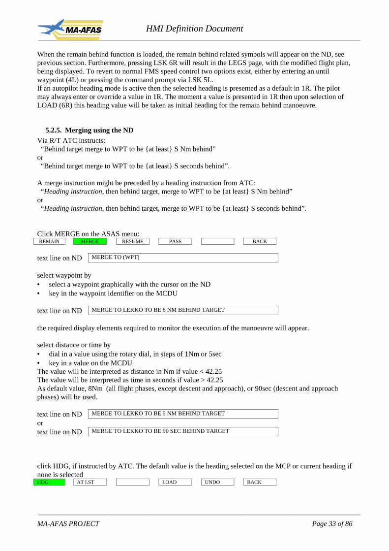
When the remain behind function is loaded, the remain behind related symbols will appear on the ND, seeprevious section. Furthermore, pressing LSK 6R will result in the LEGS page, with the modified flight plan,being displayed. To revert to normal FMS speed control two options exist, either by entering an untilwaypoint (4L) or pressing the command prompt via LSK 5L.If an autopilot heading mode is active then the selected heading is presented as a default in 1R. The pilotmay always enter or override a value in 1R. The moment a value is presented in 1R then upon selection ofLOAD (6R) this heading value will be taken as initial heading for the remain behind manoeuvre.
5.2.5. Merging using the NDVia R/T ATC instructs: “Behind target merge to WPT to be {at least} S Nm behind”or “Behind target merge to WPT to be {at least} S seconds behind”.
A merge instruction might be preceded by a heading instruction from ATC: “Heading instruction, then behind target, merge to WPT to be {at least} S Nm behind”or “Heading instruction, then behind target, merge to WPT to be {at least} S seconds behind”.
Click MERGE on the ASAS menu:REMAIN MERGE RESUME PASS BACK
text line on ND MERGE TO (WPT)
select waypoint by• select a waypoint graphically with the cursor on the ND• key in the waypoint identifier on the MCDU
text line on ND MERGE TO LEKKO TO BE 8 NM BEHIND TARGET
the required display elements required to monitor the execution of the manoeuvre will appear.
select distance or time by• dial in a value using the rotary dial, in steps of 1Nm or 5sec• key in a value on the MCDUThe value will be interpreted as distance in Nm if value < 42.25The value will be interpreted as time in seconds if value > 42.25As default value, 8Nm (all flight phases, except descent and approach), or 90sec (descent and approachphases) will be used.
text line on ND MERGE TO LEKKO TO BE 5 NM BEHIND TARGET
ortext line on ND MERGE TO LEKKO TO BE 90 SEC BEHIND TARGET
click HDG, if instructed by ATC. The default value is the heading selected on the MCP or current heading ifnone is selectedHDG AT LST LOAD UNDO BACK

HMI Definition Document____________________________________________________________________________________________________________
____________________________________________________________________________________________________________
MA-AFAS PROJECT Page 34 of 86
text line on ND HDG 170 THEN MERGE TO LEKKO TO BE 5 NM BEHIND TARGET
click AT LST (at least), if requested by ATC.HDG AT LST LOAD UNDO BACK
text line on ND MERGE TO LEKKO TO BE AT LEAST 5 NM BEHIND TARGET
click LOAD to load the instruction into the FMS (modified flightplan).LOAD AT LST LOAD UNDO BACK
text line on ND MERGE TO LEKKO TO BE AT LEAST 5 NM BEHIND TARGET
to execute this manoeuvre click EXEC (modified flightplan becomes active flightplan)EXEC ERASE BACK
text line on ND
The manoeuvre is activated and executed by the FMS. The main menu is displayed in the softkeys area.
Figure 5-2 Merging function on the ND
The spacing deviation (SDEV) indicator and deviation trend remain displayed during the entire manoeuvre.

HMI Definition Document____________________________________________________________________________________________________________
____________________________________________________________________________________________________________
MA-AFAS PROJECT Page 35 of 86
Merging specific display elements:Name Symbol Applicable in mode RemarksLongitudinal spacingdeviation scale (W) andpointer (M)
MAPPLAN
Scale runs from requiredspacing distance +/- 1Nm or required spacingtime +/- 10 secLength scale: 33mmFont height: 3.5mmDigital display ofabsolute value of SDEVlocated at bottom ofscale when SDEVexceeds 1Nm or 10 secand located at top ofscale when SDEV fallsbelow –1 Nm or –10 sec
Deviation trend indicator(G)
MAPPLAN
originates at center ofdeviation scalelength gives deviationchange in one minutebased on correctedcurrent closure rate(relative groundspeedtowards the mergepoint).
Selected target aircraft(M)
MAPPLAN
Symbol filled, colourmagenta.
Reference indicatedairspeed or mach numberfor remaining behind 1,Vremain, Mremain (W)
MAPPLAN
Below SDEV digitalindicationFont height 3.5 mmComputed withgroundspeed of targetaircraft and ownshipbaro altitudeIAS or Mach depends ontarget speed of the targetaircraft
Spacing symbol (G) MAPPLAN
Indicates map position ofthe ownship at which therequired spacing will bereachedFont height 3.5 mm
Active ASAS modeindication (G)
MAPPLANPROF
Location: adjacent towind info in upper leftcorner. ”D” for distance-based, “T”for time-basedFont height: 3,5mm

HMI Definition Document____________________________________________________________________________________________________________
____________________________________________________________________________________________________________
MA-AFAS PROJECT Page 36 of 86
Note 1 - The VREMAIN display element can be removed from the ND provided that the commanded airspeed for thisoperation is shown on the PFD.
After merging at the designated waypoint the merging automatically transfers into a remain behind situation.
5.2.5.1. Merging in detail.
The merging function is used to explain here in detail as an example of how the ND interaction is used andhow the subsequent steps are to be taken. The merging function is taken as an example because it containsall relevant elements.
Step NDInitial state, main menu presented.
Performed actions:RCL button pressed
Next step:Select target aircraft
Target selected.
Performed actions:Target selected
Next step:Press Asas and Merge button touse selected target.

HMI Definition Document____________________________________________________________________________________________________________
____________________________________________________________________________________________________________
MA-AFAS PROJECT Page 37 of 86
Merge selected.
Performed actions:Merge selected and cursorpositioned over waypoint prior toselection.
Next step:Select waypoint.
Waypoint selected.
Performed actions:Waypoint selected.Along track deviation pointerpresented.
Next step:Adapt values and press LOADbutton to upload manoeuvre intoFMS.

HMI Definition Document____________________________________________________________________________________________________________
____________________________________________________________________________________________________________
MA-AFAS PROJECT Page 38 of 86
Merge function loaded in the FMSand ready for review/execution.
Performed actions:Load selected.
Next step:Press EXEC button.
Merge function activated.Merging and acquisition inprogress.
Next step:Monitor speed reduction uponreaching the required spacing.

HMI Definition Document____________________________________________________________________________________________________________
____________________________________________________________________________________________________________
MA-AFAS PROJECT Page 39 of 86
Merging finalised. Remain behindtracking automatically initiated
Next step:Cancel remain behind functionupon ATC discretion.
5.2.6. Merging using the MCDUVia R/T ATC instructs: “Behind target merge to WPT to be {at least} S Nm behind”or “Behind target merge to WPT to be {at least} S seconds behind”.or “Heading instruction, then behind target, merge to WPT to be {at least} S Nm behind”or “Heading instruction, then behind target merge to WPT to be {at least} S seconds behind”.
The MERGE page is accessed by pressing by LSK 3R on the ASAS page.
MERGE 1/1 TO WPT HDG
1L ��� – – – 1R
2L 2R
DIST /SEP3L �� 3R
TIME /SEP4L �� 4R
5L 5R
6L <RETURN 6R
When the merging function is loaded, the merging related symbols will appear on the ND, see previoussection. When the instruction includes an at least statement then this can be entered by inserting the “plus”symbol either before or after the entered value, e.g. +8 or 8+. If an autopilot heading mode is active then theselected heading is presented as a default in 1R. The pilot may always enter or override a value in 1R. The
HMI Definition Document____________________________________________________________________________________________________________
____________________________________________________________________________________________________________
MA-AFAS PROJECT Page 40 of 86
moment a value is presented in 1R then upon selection of LOAD (6R) this heading value will be taken asinitial heading for the merge manoeuvre. If no heading value is presented in 1R (neither entry nor defaultnor entry/default cleared) then upon selection of LOAD the FMS will generate a direct to leg to the mergepoint as defined in 1L.
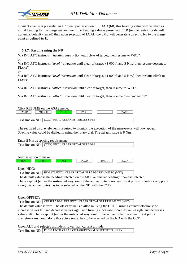
5.2.7. Resume using the NDVia R/T ATC instructs: ”heading instruction until clear of target, then resume to WPT”.orVia R/T ATC instructs: ”level instruction until clear of target, {1 000 ft and S Nm,}then resume descent toFLxxx”.orVia R/T ATC instructs: ”level instruction until clear of target, {1 000 ft and S Nm,} then resume climb toFLxxx”.
Via R/T ATC instructs: ”offset instruction until clear of target, then resume to WPT”.
Via R/T ATC instructs: ”offset instruction until clear of target, then resume own navigation”.
Click RESUME on the ASAS menu:REMAIN MERGE RESUME PASS BACK
Text line on ND (XXX) UNTIL CLEAR OF TARGET 8 NM
The required display elements required to monitor the execution of the manoeuvre will now appear.Spacing value could be dialled in using the rotary dial. The default value is 8 Nm.
Enter 5 Nm as spacing requirementText line on ND (XXX) UNTIL CLEAR OF TARGET 5 NM
Next selection to make:HDG OFFSET ALT LOAD UNDO BACK
Upon HDG:Text line on ND HDG 170 UNTIL CLEAR OF TARGET 5 NM RESUME TO (WPT)
The default value is the heading selected on the MCP or current heading if none is selected.The waypoint (either the instructed waypoint of the active route or –when it is at pilots discretion- any pointalong this active route) has to be selected on the ND with the CCD.
Upon OFFSET:Text line on ND OFFSET 5 NM LEFT UNTIL CLEAR OF TARGET RESUME TO (WPT)
The default value is zero. The offset value is dialled in using the CCD. Turning counter clockwise willincrease values left and decrease values right, and turning clockwise increases values right and decreasesvalues left. The waypoint (either the instructed waypoint of the active route or –when it is at pilotsdiscretion- any point along this active route) has to be selected on the ND with the CCD.
Upon ALT and selected altitude is lower than current altitude:Text line on ND FL 310 UNTIL CLEAR OF TARGET 5 NM DESCENT TO (XXX)

HMI Definition Document____________________________________________________________________________________________________________
____________________________________________________________________________________________________________
MA-AFAS PROJECT Page 41 of 86
The altitudes have to be dialed in using the rotary dial (in a similar way as on a mode control panel forselecting an altitude). The default value is the target altitude selected on the MCP, thereafter one click willadjust the value by 100 ft.
Upon ALT and selected altitude is higher than current altitude:Text line on ND FL 240 UNTIL CLEAR OF TARGET 5 NM CLIMB TO (XXX)
The altitudes have to be dialled in using the rotary dial. The default value is the target altitude selected onthe MCP, thereafter one click will adjust the value by 100 ft.
to acknowledge click LOAD to load the instruction into the FMS (modified flightplan).HDG OFFSET ALT LOAD UNDO BACK
Text line on ND FL240 UNTIL CLEAR OF TARGET 5 NM CLIMB TO FL360
to execute this manoeuvre click EXEC (modified flightplan becomes active flightplan and main menu isdisplayed in softkeys area).
EXEC ERASE BACK
Text line on ND
Note: the execute function is conform the baseline FMS philosophy.
Resume specific display elements:Name Symbol Applicable in mode RemarksSelected target aircraft(M)
MAPPLAN
Symbol filled, colourmagenta.Font height 2.5 mm
Closure rate (M) MAPPLAN
Value in kts. Locationadjacent to indicatedairspeed or mach numberin data tagLateral crossing resumewhen clear and lateraloffset to overtake only.Font height 3.5 mm
Spacing circle aroundtarget (W)
MAPPLAN
All manoeuvres, exceptlateral crossing resumewhen clear
Spacing area aroundtarget (W)
PROF All manoeuvres, except‘lateral crossing resumewhen clear’
ASAS no go headingindication (A)
MAPPLAN
All manoeuvres, exceptlateral crossing resumewhen clearWhen actual heading is

HMI Definition Document____________________________________________________________________________________________________________
____________________________________________________________________________________________________________
MA-AFAS PROJECT Page 42 of 86
in the amber band therequired spacing will beinfringed.
ASAS no go verticalspeed indication (A)
PROF All manoeuvres except‘lateral crossing resumewhen clear’When actual verticalspeed is in the amberband the requiredspacing will be infringed
Closest point ofapproach (G)
MAPPLAN
Symbol size: 5x5 mmTxt font height: 3.5mmNon scalable
Indicates map position ofclosest point of approach(CPA)
5.2.8. Resume using the MCDUVia R/T ATC instructs: ”heading instruction until clear of target, then resume to WPT”or ”level instruction until clear of target, {S Nm and 1 000 ft,} then resume descent to FLxxx”or ”level instruction until clear of target, {S Nm and 1 000 ft,} then resume climb to FLxxx”or ”offset instruction until clear of target, then resume to WPT”or ”offset instruction until clear of target, then resume own navigation”
The RESUME page is accessed by pressing by LSK 5R on the ASAS page.
RESUME 1/1 HDG TO WPT
1L – – – – – – – – 1R
OFFSET2L – – – 2R
3L 3R
INIT ALT DESCENT TO4L – – – – – – – – – – 4R
DIST /SEP CLIMB TO5L – – – – – – – 5R
6L <RETURN 6R

HMI Definition Document____________________________________________________________________________________________________________
____________________________________________________________________________________________________________
MA-AFAS PROJECT Page 43 of 86
Upon entry of the RESUME TO WPT, the entry will be displayed and the other entry fields will remaindashed, or become dashed if either a descent to or climb to altitude had been entered:
RESUME 1/1 HDG TO WPT
1L – – – – – – 1R
OFFSET2L – – – 2R
3L 3R
INIT ALT DESCENT TO4L – – – – – – – – – – 4R
DIST /SEP CLIMB TO5L – – – – – – – 5R
6L <RETURN LOAD> 6R
Upon entry of DESCENT TO ALTITUDE (and similar for CLIMB TO ALTITUDE) the entry will bedisplayed and the spacing value will be set to 8 Nm, the other entry fields will remain/become dashed. Thepilot could enter another spacing value.
RESUME 1/1 HDG TO WPT
1L – – – – – – – – 1R
OFFSET2L – – – 2R
3L 3R
INIT ALT DESCENT TO4L – – – – – – 4R
DIST /SEP CLIMB TO5L 8 – – – – – 5R
6L <RETURN LOAD> 6R
Upon LOAD, the manoeuvre will be loaded into the modified flight plan which can be executed uponEXEC. The LEGS page will be presented.
5.2.9. Passing using the NDVia R/T ATC instructs: “Behind target, pass {S Nm} behind then resume to WPT”or “Below target, pass below, {S Nm and 1 000 ft,} descent to FLxxx”or “Above target, pass above, {S Nm and 1 000 ft,} climb to FLxxx”

HMI Definition Document____________________________________________________________________________________________________________
____________________________________________________________________________________________________________
MA-AFAS PROJECT Page 44 of 86
or “To the (left | right) pass {S Nm} abeam target then resume to WPT”
The pass abeam instruction has been labelled as “post MA-AFAS”, and will therefore not be considered anyfurther in this document.
On the ND menu:
click PASS on the ASAS menuREMAIN MERGE RESUME PASS BACK
Text line on ND PASS (XXX)
Click BEHIND, BELOW or ABOVE according to ATC’s instruction:BEHIND BELOW ABOVE LOAD UNDO BACK
text line on ND PASS 8 NM BEHIND TARGET THEN RESUME TO (WPT)
ortext line on ND PASS BELOW TARGET 8 NM DESCENT TO (XXX)
ortext line on ND PASS ABOVE TARGET 8 NM CLIMB TO (XXX)
The required display elements required to monitor the execution of the manoeuvre will now appear.The value should be dialled in with the rotary dial, the default value is 8Nm.
The waypoint should be selected with the CCD on the ND. The altitude should be dialled in with the rotarydial, the first click will give the target altitude as set on the Mode Control Panel.
to acknowledge click LOADBEHIND BELOW ABOVE LOAD UNDO BACK
to execute this manoeuvre click EXECEXEC ERASE BACK
The manoeuvre is activated and executed by the FMS.

HMI Definition Document____________________________________________________________________________________________________________
____________________________________________________________________________________________________________
MA-AFAS PROJECT Page 45 of 86
Pass specific display elements:Name Symbol Applicable in mode Remarks
Selected target aircraft(M)
MAPPLAN
Symbol filled, colourmagenta.
Spacing circle aroundtarget (W)
MAPPLAN
Spacing area aroundtarget (W)
PROF
No go heading indication(A)
MAPPLAN
When actual heading isin the amber band therequired spacing will beinfringed
No go vertical speedindication (A)
PROF When actual verticalspeed is in the amberband the requiredspacing will be infringed
5.2.10. Passing using the MCDUVia R/T ATC instructs: “Behind target, pass {S Nm} behind then resume to WPT”or “Below target, pass below, {S Nm and 1 000 ft,} descent to FLxxx”or “Above target, pass above, {S Nm and 1 000 ft,} climb to FLxxx”
The PASS page is accessed by pressing LSK 6R on the ASAS page.

HMI Definition Document____________________________________________________________________________________________________________
____________________________________________________________________________________________________________
MA-AFAS PROJECT Page 46 of 86
PASS 1/1 BEHIND, TO WPT
1L – – – – – 1R
2L 2R
BELOW, DESCENT TO3L – – – 3R
ABOVE, CLIMB TO ALT /SEP4L – – – – – 4R
DIST /SEP5L – – 5R
6L <RETURN 6R
Upon entry of a waypoint in 1L or and altitude value in 3L or 4L:
PASS 1/1 BEHIND, TO WPT
1L – – – – – 1R
2L 2R
BELOW, DESCENT TO3L – – – 3R
ABOVE, CLIMB TO ALT /SEP4L – – – 1000 4R
DIST /SEP5L 8 5R
6L <RETURN LOAD> 6R
The default spacing value of 8Nm and 1000ft will be displayed upon entering a selection in 1L, 3L or 4L.The flight crew has the possibility to override this value. Entering a waypoint in 1L will result in dashes in3L and 4L, the same applies for entries in 3L and 4L (i.e. dashes in the other data fields). Pressing 6R willresult in a modified flight plan being calculated and an automatic transfer to the LEGS page for review ofthe modified flight plan.

HMI Definition Document____________________________________________________________________________________________________________
____________________________________________________________________________________________________________
MA-AFAS PROJECT Page 47 of 86
Figure 5-3 Pass Behind monitoring symbology (MAP and PROF mode)
5.2.11. Simplified display conceptBased on the assumption that the FMS is used to its full potential only in combination with CPDLC datalinkseveral simplifications in the HMI can be made for manual entry of ATC instructions received via R/T.This section presents an alternate design concept based on the notion that information has to be selected fordisplay, in lieu of making entries to modify the FMS trajectory. If the information is selected for display theflight crew could use standard AP modes to carry out the instruction, the only addition is FMS SPD modefor the remain behind function. The ASAS softkey and all the layers below it could be deleted, all displayfeatures can be selected or set with use of the CCD at the target aircraft. Some example displays are givenbelow.

HMI Definition Document____________________________________________________________________________________________________________
____________________________________________________________________________________________________________
MA-AFAS PROJECT Page 48 of 86
It should be noted that this alternate display concept can not be used to load the instruction into the FMS,too many (optional) parts of the instruction are not entered by the pilot, e.g. heading, at least, resumewaypoint. Items a pilot can perfectly integrate for these short duration manoeuvres, which fits into the firstimplementation variant i.e. R/T and use of standard AP modes for guidance (with the added FMS speedguidance for merge and remain behind manoeuvres).
5.3. ASAS in MAS with CPDLC support
ASAS instructions via CPDLC behave exactly the same as any CPDLC message. So, the instruction ispresented on the ND and MCDU. The crew can choose to implement the instruction in the flightplan andsubsequently respond to ATC, or first respond to ATC and then implement the instruction in the flightplan.These are, just like any CPDLC instruction, separate issues. Responding to ATC and implementing theinstruction are not automatically coupled, flight planning task and communication task remain separated.These tasks can be performed in parallel by the pilot choosing his own order of actions. For example, whenreceiving a complex instruction from ATC, it may be worthwhile checking the instruction with the FMSbefore responding to ATC and therefore the pilot can select LOAD and see how the FMS incorporates theATC instruction in the modified flightplan. If the result is satisfactory, the pilot can respond to ATC andexecute the modified flightplan which becomes the active flightplan upon the EXEC command. If on theother hand the ATC instruction is less complex and/or the pilot is confident that the ATC instruction can beaccepted without any problem, he will respond to ATC and after that, the pilot can LOAD and EXEC theinstruction. This leaves the pilot the freedom of choosing the order of actions as deemed appropriate for thesituation.The separate LOAD and EXEC steps are in line with any flightplan modification performed by the FMS.When the pilot changes something in the flightplan, this becomes the modified flightplan which can beexecuted by using the EXEC command. An ATC instruction is in fact treated in the same way, upon an ATCuplink the pilot can LOAD it to the FMS (modified flightplan to be exact) which can be regarded as anypilot edit action. Executing the modified flightplan is done by the EXEC command, whether the modifiedflightplan contains an ATC instruction or a pilot inserted modification is transparent.
5.3.1. Remain behind using the ND (with CPDLC)Upon uplink of the CPDLC message the ND will contain:
text line on ND REMAIN <VALUE> NM BEHIND <TARGET ID>
or

HMI Definition Document____________________________________________________________________________________________________________
____________________________________________________________________________________________________________
MA-AFAS PROJECT Page 49 of 86
text line on ND REMAIN <VALUE> SEC BEHIND <TARGET ID>
ortext line on ND REMAIN AT LEAST <VALUE> NM BEHIND <TARGET ID>
ortext line on ND REMAIN AT LEAST <VALUE> SEC BEHIND <TARGET ID>
ortext line on ND HDG <VALUE> THEN REMAIN …… (as above)
With below the following menu to reply to ATC:WILCO STBY UNABLE LOAD BACK
To clear the message:CLEAR LOAD BACK
5.3.2. Remain behind using the MCDU (with CPDLC)The remain behind CPDLC message will be handled like any other CPDLC message.
5.3.3. Merging using the ND (with CPDLC)Upon uplink of the CPDLC message the ND will contain:
text line on ND MERGE TO <WPT ID> TO BE <VALUE> NM BEHIND <TARGET ID>
ortext line on ND MERGE TO <WPT ID> TO BE <VALUE> SEC BEHIND <TARGET ID>
ortext line on ND MERGE TO <WPT ID> TO BE AT LEAST <VALUE> NM BEHIND <TARGET ID>
ortext line on ND MERGE TO <WPT ID> TO BE AT LEAST <VALUE> SEC BEHIND <TARGET ID>
ortext line on ND HDG <VALUE> THEN MERGE ……(as above)
With below the following menu to reply to ATC:WILCO STBY UNABLE LOAD BACK
To clear the message:CLEAR LOAD BACK
5.3.4. Merging using the MCDU (with CPDLC)The merging CPDLC message will be handled like any other CPDLC message.
5.3.5. Resume using the ND (with CPDLC)Upon uplink of the CPDLC message the ND will contain:
text line on ND HDG INSTRUCTION UNTIL CLEAR OF <TARGET ID> THEN RESUME TO <WPT>
ortext line on ND OFFSET INSTRUCTION UNTIL CLEAR OF <TARGET ID> THEN RESUME TO

HMI Definition Document____________________________________________________________________________________________________________
____________________________________________________________________________________________________________
MA-AFAS PROJECT Page 50 of 86
<WPT>
ortext line on ND LEVEL INSTRUCTION UNTIL CLEAR OF <TARGET ID> THEN RESUME CLIMB
TO <ALT>
With below the following menu to reply to ATC:WILCO STANDBY UNABLE LOAD BACK
To clear the message:CLEAR LOAD BACK
5.3.6. Resume using the MCDU (with CPDLC)The overtaking CPDLC message will be handled like any other CPDLC message.
5.3.7. Passing using the ND (with CPDLC)Upon uplink of the CPDLC message the ND will contain:
text line on ND PASS BEHIND <TARGET ID> THEN RESUME TO <WPT ID>
ortext line on ND PASS BELOW <TARGET ID>, DESCENT TO <ALT>
ortext line on ND PASS ABOVE <TARGET ID>, CLIMB TO <ALT>
With below the following menu to reply to ATC:WILCO STANDBY UNABLE LOAD BACK
To clear the message:CLEAR LOAD BACK
The separation distance to maintain is optional in the clearance.
5.3.8. Passing using the MCDU (with CPDLC)The passing CPDLC message will be handled like any other CPDLC message.

HMI Definition Document____________________________________________________________________________________________________________
____________________________________________________________________________________________________________
MA-AFAS PROJECT Page 51 of 86
5.4. ASAS in FFAS
5.4.1. Activating Autonomous Operation functionalityVia R/T ATC instructs that the crew should activate their ASAS AO system
On the ND:
Click A-OPSOPTION DLINK ASAS TFC A-OPS CNCL
On the ND, the “A-OPS” indication appears indicating that conflict detection and resolution functionality isactive.
Or on the MCDU:On the ASAS page (main function key ASAS) 1L to activate AUTO-OPS:
ASAS 1/1 AUTO-OPS ON
1L < DESEL 1R
TARGET CODE2L ����� 2R
3L 3R
4L 4R
5L 5R
6L 6R
1L toggles between “SEL” and “DESEL”, the field behind AUTO-OPS toggles between ON (invertedvideo, magenta) and OFF.
In conflict situations two ASAS pages will be available. Page 2 is identical to the previous described ASASpage to activate autonomous operation functions and to select limited delegation functions. The first ASASpage is now enabling the selection of different conflict resolutions. The preferred, i.e. most economical orthe one opted for by the airline company as in the example below) is presented in 1L, and the least preferredresolution is presented in 3L or 5L depending on the resolutions (LAT, VERT, SPEED vs. LAT-1, LAT-2,VERT-1, VERT-2, SPEED). A maximum of three resolution will be presented for the co-operative situation(speed will only be presented if it provides a reasonable resolution, e.g. within speed limits) , and amaximum of five resolutions for the priority and no priority situations (again only provide a speed resolutionif reasonable, e.g. maximum 20 kts speed change).The selected conflict resolution, only one at a time, is displayed in magenta, inverted video.

HMI Definition Document____________________________________________________________________________________________________________
____________________________________________________________________________________________________________
MA-AFAS PROJECT Page 52 of 86
ASAS A-OPS 1/2 DIST TIME FUEL AT
1L <LAT-1 +12 +00:51 +0.1 LIMM 1R
2L <LAT-2 +15 +00:55 +0.1 2R
3L <VERT-1 0 +00:16 +0.0 3R
4L <VERT-2 0 +00:20 +0.1 4R
5L <SPD 0 –00:06 +0.2 5R
6L LOAD> 6R
Autonomous Operation specific display elements:Name Symbol Applicable in mode RemarksConflicting aircraft,-co-operative situ (A)-no priority situ (D-G)-priority situ (GR)
MAPPLAN
Symbol filled and amberLabel is extended withtime to conflict.
Conflict area,- co-operative situ (A),
with mandatory turndirection (G)
MAPPLAN
Protected Airspace Zone(PAZ) at CPA withgreen line indicatingmandatory direct of turn.Symbol reflectsminimum separationvolume size.Amber track linebetween intruder andcentre of PAZ.PAZ scaled to actualsize.
Conflict area,-no priority situ (D-G)-priority situa (GR)
MAPPLAN
Protected Airspace Zone(PAZ) at CPA includingdark green route ofintruder.Symbol reflectsminimum separationvolume size and is scaledto actual size.
No go heading indication-co-operative situ (A)
MAPPLAN

HMI Definition Document____________________________________________________________________________________________________________
____________________________________________________________________________________________________________
MA-AFAS PROJECT Page 53 of 86
No go vertical speedindication,-co-operative situ (A)
PROF
Conflict area,- co-operative situ (A),
with mandatory climb/descent direction (G)
PROF Protected Airspace Zone(PAZ) at CPA withgreen lines indicatingmandatory direction ofclimb/descentSymbol reflectsminimum separationvolume size.
Conflict area,-no priority situa (D-G)-priority situ (GR)
PROF Protected Airspace Zone(PAZ) at CPASymbol reflectsminimum separationvolume size.
Active ASAS modeindication (G)
MAPPLANPROF
Location: adjacent towind info in upper leftcorner.Font height: 3,5mm
Separation violation (R) MAPPLAN
Separation violation (R) PROF
5.4.2. Types of conflicts in FFAS
The following conflict situations can occur:Time to conflictwhen detected(minutes)Values to check
State and or intentused
Priority Resolution
Tdetect> 20 state & intent N/A N/A

HMI Definition Document____________________________________________________________________________________________________________
____________________________________________________________________________________________________________
MA-AFAS PROJECT Page 54 of 86
6 < Tdetect < 20 state & intent Priority N/A6 < Tdetect < 20 state & intent No priority Lateral6 < Tdetect < 20 state & intent No priority Vertical6 < Tdetect < 20 state & intent No priority SpeedTdetect < 6 state N/A LateralTdetect < 6 state N/A VerticalTdetect < 6 state N/A Speed6 < Tdetect < 20but Tconflict <5 *)
state N/A Lateral
6 < Tdetect < 20but Tconflict <5 *)
state N/A Vertical
6 < Tdetect < 20but Tconflict <5 *)
state N/A Speed
*) depicts the situation in which the conflict was detected when time to conflict was more than 6 minutes butdue to late or no action from the crew who had to give way the conflict remains in place. When time toconflict becomes less than 5 minutes, the co-operative method is to be applied.
The subsequent action from the moment the conflict was detected until the solution of the conflict aredescribed here for all above mentioned situations.
5.4.3. Conflicts detected above the threshold time (priority rules)The conflict will be presented on the ND once the time to conflict has dropped under the maximum lookahead time of 20 minutes and after the priority has been determined between the intruder and ownship.When the conflict is within the maximum look ahead time and the ownship has priority the conflict is forinformation only. If the intruder has priority the conflict is presented together with at least one resolutionroute. The colour and symbol coding of the conflict indicates whether the ownship has priority or not.
5.4.4. Conflicts detected below the threshold time (co-operative rules)The conflict will be presented on the ND just like in the priority rules situation. The rules of the air in thiscase demand that the conflict is solved in a mandatory direction which is manoeuvring in the directionwhich requires the smallest change in flight path vector. This can be either lateral, vertical, longitudinal orcombinations of them. The MA-AFAS system covers this by presenting at least one resolution route to thecrew which can be executed.
5.5. Taxi management
5.5.1. Display elements to display on the taxi mapThe taxi map can contain a lot of detailed information for navigational support to the crew. Presentingeverything at all times will overload the display and therefore some items will be shown only when a smallrange is selected, other items are selectable by the crew. Items with high importance will always be shown.The following four categories are defined:
Ssk - selectable by pilot through softkeysSge - selectable by pilot through graphical elements in taxi mapM - mandatory, always visibleA - automatic declutter with range settings

HMI Definition Document____________________________________________________________________________________________________________
____________________________________________________________________________________________________________
MA-AFAS PROJECT Page 55 of 86
In addition, a number of items which were initially foreseen to be included but were decided to leave out arealso mentioned here for completeness:
out - initially foreseen in MA-AFAS, but decided to disregard.
Map Attributes:• Runway designators (M)• Taxiway designators (Ssk and Sge)• Buildings (A or M), and most likely A• Gate positions (Ssk and Sge), but also A• Gate designators (Ssk and Sge), but also A• Magnetic North out• Temp unavailable runways out• Temp unavailable taxiways out• Temp speed restrictions out• Temp weight restrictions out• Any special procedures out• Holding point designators (Ssk and Sge)
Traffic:• Other aircraft (Ssk), possibly also A• Ground vehicles (Ssk), possibly also A• Speed of other aircraft out• Heading of other aircraft, grahically (M)• Identifier of other aircraft (Ssk and Sge), possibly also A• Speed of ground vehicles out• Heading of ground vehicles out• Identifier of ground vehicles out• Target aircraft out
Taxi route (CPDLC uplinked):• Active stopbars (M)• Taxi route including gate (M)• Cleared taxi route (M)• Waypoint info out
5.5.2. Taxi without CPDLC supportVia R/T ATC instructs: “Taxi from <current position> via <position> to <taxi destination>”
On the ND the pilot select those items on the taxi map (like a specific gate, traffic etc) which aids him tointerpret the R/T instruction. No specific ND functionality is required for handling R/T taxi instructions.
5.5.3. Taxi with CPDLC supportUpon the receipt of an uplink, the message will be shown on the text line on the ND.

HMI Definition Document____________________________________________________________________________________________________________
____________________________________________________________________________________________________________
MA-AFAS PROJECT Page 56 of 86
text line on ND TEXT OF ATC UPLINK
With below the following menu to reply to ATC:WILCO STANDBY UNABLE LOAD BACK
After WILCO or UNABLE the message can be cleared:CLEAR LOAD BACK
In addition the taxi route will be presented on the TAXI display modes.
5.5.4. Taxi with CPDLC on the MCDU.The taxi CPDLC messages will be handled like any other CPDLC message.
5.6. Precision approach and landing
No significant changes are foreseen when applying precision approach and landing, although the differencebetween GBAS and SBAS needs some attention here. Precision approach and landing is based on GNSSwith GBAS being a separate approach system or SBAS being just a position sensor for the FMS.
5.6.1. SBASThe SBAS version translates into FMS approaches in which the complete approach procedure is known bythe FMS and FMS guidance is used. Regarding HMI there is only one requirement which is that is should beclear from the PFD and ND Approach mode that localizer and glide slope deviation indications are GNSSvia FMS generated and should be clearly differ from ILS indications. Both PFD and ND APP mode areaffected by the type of approach selected: the source is annunciated (ILS1, ILS2, GBAS1, GBAS2, SBAS1,SBAS2, etc) and the deviation pointers have a unique shape for each approach type (ILS - diamond, GBAS -triangle, SBAS - square, etc.). On the ND the source annunciation is located in the right-hand upper cornertogether with the applicable approach information. On the PFD the source annunciation is located below theglide scale and therefore to the right of the localizer scale.
5.6.2. GBASFor GBAS the situation is different. The approach procedure is included in the GBAS system and during thearrival there is a transfer from FMS to the GBAS system. This transfer can be handled in the same manneras currently the transfer from FMS to ILS (although in many cases the procedure prescribes that the transferfrom FMS to ILS is performed via a heading select and altitude select mode in between).While flying the descent on FMS, the GBAS approach mode should be armed (comparable with ILS, set thecorrect ILS frequency and course and select approach mode). When the FMS route intercepts the GBASapproach route the armed GBAS approach mode becomes the active mode until touch down. Theconsequence for the displays is described in the SBAS section above.
5.7. CPDLC (including 4DTN)
Both 4DTN and CPDLC is described in this chapter. There is no fundamental difference between a tacticalCPDLC message exchange between ATC and MA-AFAS FMS and the strategic message exchange as partof 4DTN. For 4DTN RTE1 or RTE2 (whichever is NOT active at the moment) will be used for trajectorynegotiation. Both CPDLC and 4DTN uplinks will be uploaded in the MA-AFAS FMS for inclusion in theFMS modified route.

HMI Definition Document____________________________________________________________________________________________________________
____________________________________________________________________________________________________________
MA-AFAS PROJECT Page 57 of 86
5.7.1. CPDLC using the NDUpon the receipt of an uplink, a dedicated softkey labelled “ATC” is presented adjacent to and to the left ofthe own aircraft symbol. Pressing this dedicated softkey -or alternatively selecting ATC via the menu- willimmediately show the ATC uplink information and associated softkeys. The message will be shown on thetext line on the ND.
text line on ND TEXT OF ATC UPLINK < > 1/X
Two scroll buttons appear when the message is longer than the one line available on the display. Scrollingwill occur on a line-by-line principle.< >
The indication 1/X indicates the number of messages received which are not replied by the crew yet.
With below the following menu to reply to ATC:WILCO STBY UNABLE LOAD NEXT BACK
orAFFIRM STBY NEG LOAD NEXT BACK
orROGER STBY UNABLE LOAD NEXT BACK
After pressing either WILCO, AFFIRM, UNABLE or NEGATIVE, the following appears:CLEAR LOAD NEXT BACK
WILCO/AFFIRM/ROGER/UNABLE/NEGATIVE commands result in a direct downlink of therespective message.
CLEAR command is used to clear the message. This will still be accessible in the message log. If more thanone message was received the next message will appear.
NEXT command will show the next message in case more than one message was received. The NEXTcommand cycles through the set of uplinks which have not been replied. The replies can be given in theorder the pilot prefers.
LOAD command is used to upload the instruction to the modified flightplan of the FMS. This can be donebefore responding to the message, or after that.
STANDBY can only once be used per message. When pressed the button will change into its not activestate.
Creating a downlink is not supported by the ND. The MCDU should be used for this.
Example of a CPDLC uplink handling:Uplink received andresponse buttonsavailable

HMI Definition Document____________________________________________________________________________________________________________
____________________________________________________________________________________________________________
MA-AFAS PROJECT Page 58 of 86
Standby downlinked,only once available sonow inactive
Negative responsedownlinked
Upon clear, nextmessage presented
5.7.1.1. Specific CPDLC messages.
One category of CPDLC messages requires extra attention here, it concerns the request for informationuplinks. Unless an UNABLE is transmitted, a downlink will be prepared on the MCDU and also send at theMCDU:
5.7.2. CPDLC using the MCDU
5.7.2.1. Handling standard messages
When pressing the ATC function key on the MCDU the UPLINK page will appear in case there is an uplinkto be handled or the DOWNLINK page if not.Two separate CPDLC messages will be distinguished here: tactical and strategic messages. A tacticalmessage is an instruction which is open ended and cannot be integrated in the FMS route. A strategicmessage can be incorporated in the FMS route and translates to the pilot as a change in the route(comparable with 4DTN).
An uplink has been received with a strategic CPDLC message and the ATC function key is pressed:ATC UPLINK 1/1
01:261L < UNABLE LOAD TO RTE > 1R
2L < STANDBY WILCO > 2R
3L TEXT OF STRATEGIC 3R
ATC UPLINK MESSAGE4L 4R
5L 5R
6L �LOG DOWNLINK� 6R

HMI Definition Document____________________________________________________________________________________________________________
____________________________________________________________________________________________________________
MA-AFAS PROJECT Page 59 of 86
After pressing 1R LOAD TO RTE, the ATC uplink is included in the modified route (indicated with RTE-X, either RTE 1 or RTE 2)and can be reviewed by the crew. After that, a reply to ATC can be send via theATC UPLINK page. Directly responding with WILCO is also possible.The modified route can be executed like a normal route change made by the pilot using the EXEC key.The time (min:sec) indication just below the page title is the time available for the crew to respond beforethe time-out.
ATC UPLINK 1/101:26
1L < UNABLE 1R
2L < STANDBY WILCO > 2R
3L TEXT OF ATC UPLINK MESSAGE 3R
4L 4R
5L 5R
6L �LOG DOWNLINK� 6R
1L or 2R results in:
ATC UPLINK 1/1
1L LOAD TO RTE > 1R
2L CLEAR > 2R
3L TEXT OF ATC UPLINK MESSAGE 3R
4L 4R
5L UNABLE or WILCO 5R
6L 6R
When STANDBY is selected the UNABLE and WILCO will remain available and the CLEAR key willappear only after the pilot has selected UNABLE or WILCO, not after a STANDBY. CLEAR removes themessage from the uplink page, but the message will remain available on the log page.STANDBY is to be used if the crew needs more time to review an uplink (possibly because more urgenttasks are to be performed in the cockpit at that moment.) A STANDBY message will never be systemgenerated to avoid a time-out error. Time-outs as defined in the data link services serve as a kind of wake-upcall in case a crew does not respond to a message. When STANDBY is used, the STANDBY will disappearfrom the display.
In case a tactical CPDLC message is uplinked, the following page appears:

HMI Definition Document____________________________________________________________________________________________________________
____________________________________________________________________________________________________________
MA-AFAS PROJECT Page 60 of 86
ATC UPLINK 1/101:26
1L < UNABLE ACTIVATE > 1R
2L < STANDBY WILCO > 2R
3L TEXT OF TACTICAL ATC 3R
UPLINK MESSAGE4L 4R
5L 5R
6L �LOG DOWNLINK� 6R
Now LSK 1R presents ACTIVATE instead of LOAD TO RTE. Using ACTIVATE will result in the flightmode to change from LNAV into HDG fms and VNAV into ALT fms, V/S fms and/or SPD fms. Returningto the full FMS mode LNAV and VNAV will normally be upon responding to the RESUME OWNNAVIGATION CPDLC message:
ATC UPLINK 1/101:26
1L < UNABLE RESUME > 1R
2L < STANDBY WILCO > 2R
3L RESUME OWN NAVIGATION 3R
UPLINK MESSAGE4L 4R
5L 5R
6L �LOG DOWNLINK� 6R
Other ways to rejoin the FMS trajectory (with the RESUME CPDLC uplink) are indicated in the nextchapter: flight modes.
In case no uplink message is available when pressing the ATC button, the DOWNLINK page will appear:

HMI Definition Document____________________________________________________________________________________________________________
____________________________________________________________________________________________________________
MA-AFAS PROJECT Page 61 of 86
DOWNLINK 1/1 REQ ATC RTE
1L RTE X SEND > 1R
REQ DIRECT TO REQ HDG2L – – – – – – – –deg 2R
REQ ALT REQ SPD3L – – – – FL – – – –kts 3R
REQ OFFSET4L – – – – Nm FREE TEXT� 4R
5L 5R
6L �LOG UPLINK� 6R
On this page a number of requests can be prepared and when prepared sent. The SEND field will normallybe low lighted and when a request is prepared, the SEND field will become normally visible. When SENDis pressed, the field text will change flash SENDING for 5 seconds (or, even better, as long as the sendingtakes). After that the lowlighted SEND appears again and the requests fields become empty.
ATC
Uplink page
wilco/unable/stby
Uplink page
clear
Log page
Downlink page
edit request
Free Text page
Downlink page
sending
loglog
<Uplink received><No uplink received>
UplinkDownlinkWilco or Unable
Free Text
Return
Send
Uplink/Downlink
Clear<automatic>
Load RTE
Load RTE
Figure 5-4 Page tree structure of the ATC branch
Note: all responses used in the section are WILCO and UNABLE. However these serve as example becausefor each uplink message a specific response is defined, either WILCO/UNABLE or AFIRM/NEGATIVE orROGER/UNABLE.
5.7.2.2. Long uplink messages
In case uplink messages contain more text than lines available on the MCDU, the message will be split overmore than one page. After pressing the ATC button on the MCDU, the UPLINK page appears with the firstpart of the message:

HMI Definition Document____________________________________________________________________________________________________________
____________________________________________________________________________________________________________
MA-AFAS PROJECT Page 62 of 86
ATC UPLINK 1/101:26
1L < UNABLE LOAD TO RTE> 1R
2L < STANDBY 2R
3L TEXT OF ATC UPLINK MESSAGE 3R
TEXT OF ATC UPLINK MESSAGE4L TEXT OF ATC UPLINK MESSAGE 4R
TEXT OF ATC UPLINK MESSAGE5L TEXT OF ATC UPLINK MESSAGE 5R
6L MORE� 6R
LSK 6R gives MORE instead of DOWNLINK (LOG is also removed) indicating that the messagecontinues. When pressing MORE the second (or third, whatever is required) part of the message is shown.When the last part of the message is presented, the phrase “=END OF MESSAGE=” is indicated. PressingRETURN returns to the page containing the previous part of the message.The WILCO key becomes available when the complete message has been presented. When the last part ofthe message is presented and after that the pilot selects any other part of the message above (PAGE UP), theWILCO remains available. UNABLE and STANDBY are available from the first part of the message beingpresented.
ATC UPLINK 1/101:26
1L < UNABLE LOAD TO RTE> 1R
2L < STANDBY WILCO > 2R
3L TEXT OF ATC UPLINK MESSAGE 3R
TEXT OF ATC UPLINK MESSAGE4L TEXT OF ATC UPLINK MESSAGE 4R
=END OF MESSAGE=5L RETURN� 5R
6L �LOG DOWNLINK� 6R
5.7.2.3. More than one uplink message in queue
In case more than one uplink is sent and not replied by the crew yet, the number of messages in queue isindicated in the top line (1/3 indicating three received messages in the example below).

HMI Definition Document____________________________________________________________________________________________________________
____________________________________________________________________________________________________________
MA-AFAS PROJECT Page 63 of 86
ATC UPLINK MSG 1/301:26
1L < UNABLE LOAD TO RTE> 1R
2L < STANDBY WILCO > 2R
3L TEXT OF ATC UPLINK MESSAGE 1 3R
4L 4R
5L 5R
6L �LOG DOWNLINK� 6R
Press <NEXT PAGE> button:
ATC UPLINK MSG 2/301:26
1L < UNABLE LOAD TO RTE> 1R
2L < STANDBY WILCO > 2R
3L TEXT OF ATC UPLINK MESSAGE 2 3R
4L 4R
5L 5R
6L �LOG DOWNLINK� 6R
Using the NEXT PAGE/PREV PAGE buttons on the MCDU the pilot can ‘walk’ through the queue ofmessages. Each message can be replied independently and in the order preferred by the crew.

HMI Definition Document____________________________________________________________________________________________________________
____________________________________________________________________________________________________________
MA-AFAS PROJECT Page 64 of 86
Uplink page 1/N
wilco/unable/stby
Uplink page 1/N
clear
Log page
log
UplinkWilco or Unable
Clear
Uplink page
wilco/unable/stby
Uplink page 2/N
clear
Wilco or Unable
Clear
Log page
log
Uplink
Uplink page N/N
clear
Uplink page 2/N
wilco/unable/stby
More
Return
Wilco or Unable
Figure 5-5 Page tree structure of the uplink part only, detailing on multiple messages in the queue andmessages consisting of more than one MCDU page.
5.7.2.4. Concatenated messages
The ICAO SARP defines the capability of concatenated messages up to 5 message elements. This capabilityof creating concatenated downlink messages will not be provided by the system to the crew. Uplinkedconcatenated messages will only be used for error messages, no concatenation of ATC instructions issupported. The major reason for this is that a concatenated message may contain 5 elements which are to beresponded by one response.Handling messages by R/T or CPDLC are inherently different and concatenation as applied in R/Tcommunication has no relevance as such when applying CPDLC.
(Background for this design decision was mainly outcomes of PETAL II:http://www.eurocontrol.int/projects/eatchip/petal2/index.htm )
5.7.2.5. Responding to uplinks requiring pilot or system data
Some uplinks require the crew to respond with their intent, estimations or capabilities. For examplemessages like “when can you accept flight level”. In these cases the system prepares a response messagewhich contains data as far as known by the system. In case estimations are required, the system will preparea message text in which the crew can insert the estimates requested by ATC. Only uplink messages whichrequire a “YES” response in ATN terminology are covered here, not the WILCO/UNABLE response types..
An uplink would look like:

HMI Definition Document____________________________________________________________________________________________________________
____________________________________________________________________________________________________________
MA-AFAS PROJECT Page 65 of 86
ATC UPLINK 1/101:26
1L < UNABLE PREPARE� 1R
2L < STANDBY 2R
3L TEXT OF ATC UPLINK MESSAGE 3R
4L 4R
5L 5R
6L �LOG DOWNLINK� 6R
For example: “When can you accept FL 360?”.
Upon 1R PREPARE, the prepared downlink will be presented:
ATC UPLINK REPLY 1/101:26
1L < UNABLE SEND > 1R
2L AUTO REPLY MESSAGE TXT 2R
TIME3L ��:�� 3R
4L 4R
5L RETURN� 5R
6L �LOG DOWNLINK� 6R
Example reply: “We can accept FL 360 at: 13:09” In which the 13:09 is presented next to LSK 3L.
Where 4L is a time field either to be filled by the crew, or pre-estimates as far as available by the system.UNABLE represents the can not accept response to this message.

HMI Definition Document____________________________________________________________________________________________________________
____________________________________________________________________________________________________________
MA-AFAS PROJECT Page 66 of 86
ATC UPLINK 1/1
1L 1R
2L 2R
3L TEXT OF ATC UPLINK MESSAGE 3R
4L AUTO REPLY MESSAGE TXT 4R
5L 5R
6L CLEAR> 6R
Uplink page
Show reply
Uplink reply page
Send
Log page
log
UplinkShow reply
Clear
Send
Uplink page
Clear
Uplink
log
Figure 5-6 Page tree structure of the uplink branch, detailing on messages which require data in theresponse downlink message.
5.7.2.6. Responding to uplinks requiring event based response
Uplink which require an event based response are messages like “report reaching level XXX”. Suchmessages require an immediate response WILCO or UNABLE and when responding with WILCO, a secondresponse is to be send out when the condition is met. In this example when the new level is reached. For thepilot this process is hidden by providing the pilot with two options: UNABLE or AUTO REPORT. UponAUTO REPORT the WILCO is sent immediately and when the condition is met, a report message isdownlinked. This second downlink is transparent for the pilot, no pilot is action required.

HMI Definition Document____________________________________________________________________________________________________________
____________________________________________________________________________________________________________
MA-AFAS PROJECT Page 67 of 86
ATC UPLINK 1/101:26
1L < UNABLE AUTO REPORT > 1R
2L < STANDBY 2R
3L TEXT OF ATC UPLINK MESSAGE 3R
4L 4R
5L 5R
6L �LOG DOWNLINK� 6R
5.8. Graphical route editing
Graphical route editing means that the route can be modified with direct manipulation on the ND using theCCD. In FFAS any position can be used for drag-and-drop a route change point. In MAS publishedwaypoints can be used, but pilot defined waypoints as well.
New waypoints are created by double clicking the left hand button on the CCD while the cursor ispositioned near a waypoint or leg. The waypoint can be moved to another position with the use of the CCDand a single click fixates its new position. New waypoints are -already during the slewing- presented as partof the modified flight plan, thus connected by two lines (short dashes, white) to a preceding and followingwaypoint. During the slewing operation the bearing and distance to both connecting waypoints arepresented.If the new waypoint is dropped on the existing route then the previous intermediate part of this route isdeleted.
Clicking with the right hand button of the CCD on a waypoint will show two so-called waypoint controltags.The first control tag “DIR TO” will generate a modified route with a direct to the waypoint. Pressing thesecond control tag “CROSS” gives three adjacent data entry tags for altitude, speed and time crossingrestrictions. The data entry tags for altitude and speed tasks have the possibility to select ‘cross waypoint atmaximum’ or ‘cross waypoint at minimum’ options. After data entry the constraint selection is confirmed bya click on the data entry tag. A second click on ‘crossing’ control tag will cancel the crossing constraint(s).
A general EXEC and UNDO button are presented once a modified flight plan is generated and displayed.The undo function cancels the preceding pilot CCD action(s). The execute function activates the modifiedpart to be included into the active flight plan.

HMI Definition Document____________________________________________________________________________________________________________
____________________________________________________________________________________________________________
MA-AFAS PROJECT Page 68 of 86
Figure 5-7 Waypoint control tags selected (left), direct to selected (middle), crossing restrictions set (right)
5.9. Review of flight plan modifications
The main information elements to make decisions on flight plan modifications are:- imminent heading, altitude and speed changes- effect on distance to destination- effect on estimated fuel-on-board at destination- and effect on estimated time of arrival at destination
The heading and altitude changes can be checked in respectively the MAP and PROF display mode. Theeffect on the target speed can not be checked prior to activation. The most appropriate solution is to presenta symbol on the speed scale representing the new target speed, e.g. open circle, cyan.
The effect on distance, fuel and time at destination can be checked on the MCDU PROGESS page.
5.10. Communication with Airline Operation Centre (AOC)
Communication with the airline operation centre which requires crew actions (so, no automatic reporting)covers the following functions:
• Pre flight support• Loadsheet• Departure slot• Flight plan
• Flight planning support• Flight plan modifications (IFTM)
• Meteo*)• Meteo data base• Meteo TAF/METAR/SIGMET
• Free text
*) Meteo is only part of the AOC page structure in case the avionics package does not include FISapplications.
The AOC functions are accessible via the MCDU only, no ND support is provided. AOC functions areaccessed via the INIT/REF main page. Regarding communication functions two main options exist. Option 1

HMI Definition Document____________________________________________________________________________________________________________
____________________________________________________________________________________________________________
MA-AFAS PROJECT Page 69 of 86
would be to put all the communication functions together while option 2 would be to distribute thecommunication functions and put each communication function where it is related to. For MA-AFAS hasbeen decided that communication to ATC and the company are clearly separated so, option 1 is chosen toavoid confusion and avoid unintended communication to the wrong entity (either ATC or company). Thisresults in a design that communication to ATC is accessed via the ATC function key and communication tothe company is accessed via a COMPANY LSK on the INIT/REF page.
After pressing the COMPANY prompt on the INIT/REF page, the AOC main page appears:
C O M P A N Y
1L �F L I G H T P L A N 1R
2L �L O A D S H E E T 2R
3L �D E P S L O T 3R
4L �M E T E O R E Q M E T E O � 4R
5L �F R E E T E X T 5R
6L 6R
The page is in fact the entry menu for the AOC functions, each selection here will result in appearing theselected sub page.
5.10.1. Flight plan pageUpon selecting LSK 1L, Flight Plan, the Flight Plan page appears which has been received from AOC.Normally more than page is required for presenting the uplinked flight plan. In MA-AFAS term this flightplan page applies for the initial flight plan uplink as well of the In Flight Traffic Management (IFTM)function, although the content of the IFTM messages can be significantly smaller than a complete initialflight plan.
F L I G H T P L A N 1 / X
- - - - - - - - - - - - T O - - - -1L E O B T - - : - - Z A L T N - - - - 1R
A L T N 2 - - - - - - - - - - - - -2L - - - - - - - - - - - - - - - - - - - - - 2R
P A X - - -3L - - - - - - - - - - - - - - - - - - - - - - - - 3R
- - - - - -4L R O U T E - - - - - - - - - - 4R
E E T - - : - - N - - - - A - - -5L 5R
- - - - - - - - - - - - - - - - A - - -6L C O M P A N Y � 6R
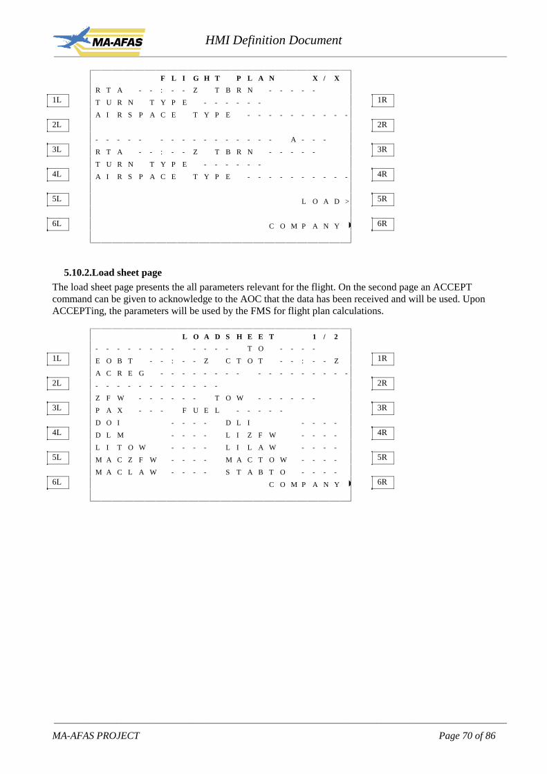
HMI Definition Document____________________________________________________________________________________________________________
____________________________________________________________________________________________________________
MA-AFAS PROJECT Page 70 of 86
F L I G H T P L A N X / X
R T A - - : - - Z T B R N - - - - -1L T U R N T Y P E - - - - - - 1R
A I R S P A C E T Y P E - - - - - - - - - -2L 2R
- - - - - - - - - - - - - - - - A - - -3L R T A - - : - - Z T B R N - - - - - 3R
T U R N T Y P E - - - - - -4L A I R S P A C E T Y P E - - - - - - - - - - 4R
5L L O A D > 5R
6L C O M P A N Y � 6R
5.10.2. Load sheet pageThe load sheet page presents the all parameters relevant for the flight. On the second page an ACCEPTcommand can be given to acknowledge to the AOC that the data has been received and will be used. UponACCEPTing, the parameters will be used by the FMS for flight plan calculations.
L O A D S H E E T 1 / 2
- - - - - - - - - - - - T O - - - -1L E O B T - - : - - Z C T O T - - : - - Z 1R
A C R E G - - - - - - - - - - - - - - - - -2L - - - - - - - - - - - - 2R
Z F W - - - - - - T O W - - - - - -3L P A X - - - F U E L - - - - - 3R
D O I - - - - D L I - - - -4L D L M - - - - L I Z F W - - - - 4R
L I T O W - - - - L I L A W - - - -5L M A C Z F W - - - - M A C T O W - - - - 5R
M A C L A W - - - - S T A B T O - - - -6L C O M P A N Y � 6R

HMI Definition Document____________________________________________________________________________________________________________
____________________________________________________________________________________________________________
MA-AFAS PROJECT Page 71 of 86
L O A D S H E E T 2 / 2
- - - - - - - - - - - - -1L - - - - - - - - - - - - - 1R
- - - - - - - - - - - - -2L - - - - - - - - - - - - - 2R
- - - - - - - - - - - - -3L - - - - - - - - - - - - - 3R
- - - - - - - - - - - - -4L - - - - - - - - - - - - - 4R
5L A C C E P T > 5R
6L C O M P A N Y � 6R
5.10.3. Departure slot page
D E P S L O T
E O B T - - - - - Z1L C T O T - - - - - Z 1R
2L 2R
3L 3R
4L 4R
5L 5R
6L C O M P A N Y � 6R
The departure slot page is used for data presenation only, no actions required.
5.10.4. Meteo pages
Note: in case only the AOC function is available in the avionics package the AOC pages are as describedabove. However, in case the avionics package has also the FIS application integrated, the meteo functionsshould be removed from the AOC pages. The flight information services like TAF, METAR and SIGMETare then accessible on the FIS pages. Whether a message is to be retrieved from AOC or the FIS applicationis completely transparent for the pilot.

HMI Definition Document____________________________________________________________________________________________________________
____________________________________________________________________________________________________________
MA-AFAS PROJECT Page 72 of 86
M E T E O L O G 1 / X
1L �T A F | E G K K | 1 1 : 1 2 1R
2L �M E T A R | E G F F | 1 1 : 1 0 2R
3L �S I G M E T | E G K K | 1 1 : 0 4 3R
4L �M E T A R | E G K K | 1 1 : 0 2 4R
5L �T A F | L E I B | 1 0 : 1 0 5R
6L �R E Q U E S T C O M P A N Y � 6R
Upon selecting 1L to 5L for TAF, METAR, SIGMET the relevant page will appear presenting the message.
T A F R E P O R T
A I R P O R T I D - - - -1L I S S U E T I M E - - - - Z 1R
V A L I D I T Y - - 0 0 / - - 0 0 Z2L 2R
T A F T E X T T A F T E X T3L T A F T E X T T A F T E X T 3R
4L 4R
5L R E Q U E S T � 5R
6L �L O G C O M P A N Y � 6R
Upon REQUEST, the request meteo page appears, described later in this section.
M E T A R R E P O R T
A I R P O R T I D - - - -1L I S S U E T I M E - - - - Z 1R
2L M E T A R T E X T M E T A R T E X T 2R
M E T A R T E X T M E T A R T E X T3L 3R
4L 4R
5L R E Q U E S T � 5R
6L < L O G C O M P A N Y � 6R

HMI Definition Document____________________________________________________________________________________________________________
____________________________________________________________________________________________________________
MA-AFAS PROJECT Page 73 of 86
S I G M E T R E P O R T
I S S U E T I M E - - - - Z1L V A L I D T O - - - - Z 1R
A R E A O F I N T E R E S T2L F R O M - - - - N - - - - - E 2R
T O - - - - S - - - - - W3L 3R
S I G M E T T E X T S I G M E T T E X T4L 4R
5L R E Q U E S T � 5R
6L �L O G C O M P A N Y � 6R
R E Q U E S T M E T E O
1L 1R
A I R P O R T2L ���� R E Q T A F > 2R
3L R E Q M E T A R > 3R
4L R E Q S I G M E T > 4R
5L 5R
6L �L O G C O M P A N Y � 6R
After having inserted the airport identifier on 2L, TAF, METAR and SIGMENT information can berequested. Upon 2R, 3R or 4R a downlink message is sent to AOC directly. Upon LOG, the meteo log pagewill appear with the most recent received meteo uplinks.
5.10.5. Free text pages
In case an uplink from AOC has been received, the message page appears. If no uplink has been received,the new message preparation page appears as depicted below.

HMI Definition Document____________________________________________________________________________________________________________
____________________________________________________________________________________________________________
MA-AFAS PROJECT Page 74 of 86
F R E E T E X T 1 / X
N E W M E S S A G E1L 1R
2L 2R
3L 3R
4L 4R
5L S E N D > 5R
6L �L O G C O M P A N Y � 6R
F R E E T E X T L O G 1 / X
1L �F R E E T E X T M E S I D | H H : M M 1R
2L �F R E E T E X T M E S I D | H H : M M 2R
3L �F R E E T E X T M E S I D | H H : M M 3R
4L �F R E E T E X T M E S I D | H H : M M 4R
5L �F R E E T E X T M E S I D | H H : M M 5R
6L �N E W M E S S A G E C O M P A N Y � 6R
Selecting one of the messages will present the page with the message.
5.11. Flight Information Services (FIS)
Access to the FIS services page is provided by pressing the FLIGHT INFO prompt on the INIT/REF page.The MCDU page is titled FLIGHT INFO.
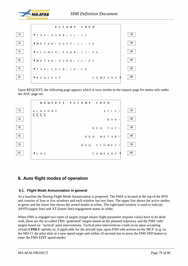
HMI Definition Document____________________________________________________________________________________________________________
____________________________________________________________________________________________________________
MA-AFAS PROJECT Page 75 of 86
F L I G H T I N F O
1L �T A F | E G K K | 1 1 : 1 2 1R
2L �M E T A R | E G F F | 1 1 : 1 0 2R
3L �S I G M E T | E G K K | 1 1 : 0 4 3R
4L �M E T A R | E G K K | 1 1 : 0 2 4R
5L �T A F | L E I B | 1 0 : 1 0 5R
6L �R E Q U E S T C O M P A N Y � 6R
Upon REQUEST, the following page appears which is very similar to the request page for meteo info underthe AOC page set.
R E Q U E S T F L I G H T I N F O
1L A I R P O R T A T I S > 1R
����2L R V R > 2R
3L R E Q T A F > 3R
4L R E Q M E T A R > 4R
5L R E Q S I G M E T > 5R
6L �L O G C O M P A N Y � 6R
6. Auto flight modes of operation
6.1. Flight Mode Annunciation in general
As a baseline the Boeing Flight Mode Annunciation is proposed. The FMA is located at the top of the PFDand consists of four or five windows and each window has two lines. The upper line shows the active modesin green and the lower line shows the armed modes in white. The right-hand window is used to indicateAP/FD (upper line) and AT (lower line) engagement status in white.
When FMS is engaged two types of targets (target means flight parameter setpoint value) have to be dealtwith, these are the so-called FMS ‘generated’ targets based on the planned trajectory and the FMS ‘edit’targets based on ‘tactical’ pilot interventions. Tactical pilot interventions could occur upon acceptingcertain CPDLC uplinks or, if applicable for the aircraft type, upon FMS edit actions on the MCP (e.g. onthe MD-11 the pilot dials in a new speed target and within 10 seconds has to press the FMS SPD button toenter the FMS EDIT speed mode).

HMI Definition Document____________________________________________________________________________________________________________
____________________________________________________________________________________________________________
MA-AFAS PROJECT Page 76 of 86
For speed control (both speed-on-elevator and speed-on-throttle) the target is either the FMS generatedspeed target <VNAV SPD mode> or after pilot intervention the FMS EDIT speed target <SPD FMS mode>is used for guidance.
Similarly for the lateral path control, either the FMS generated lateral path <LNAV mode> is used forguidance or after pilot intervention the FMS edit heading target <HDG FMS mode>.
For vertical path control two FMS sub-modes need to be considered, namely altitude and descent pathcontrol.For level-flight vertical path control either the FMS generated altitude target equals the MCP altitude (orFMS edit altitude) <VNAV PTH mode> or they differ. If they differ the a/c can be controlled to either theFMS generated altitude <VNAV PTH mode> or the FMS edit altitude <ALT FMS mode>.For non level-flight vertical path control either the FMS generated descent path <VNAV PTH mode> isactive or the FMS edit V/S target <V/S FMS mode> is active.
The issue is how to annunciate pilot intervention of FMS generated targets. Basically the mode controlledby the FMS does not change, but the target is now determined by the pilot (by accepting the CPDLC uplinkor R/T instruction). So a change in the FMA is proposed. It is also proposed to provide differentpresentations of the targets (ref. MD-11), due to the importance of mode awareness redundant feedback isdeemed necessary.1. If the pilot has selected a non-FMS mode and associated target on the MCP then the (speed, heading,altitude and/or vertical speed) target is represented by a white bow.2. If an FMS mode is engaged and the FMS generated target is active (LNAV, VNAV PATH, VNAV SPDmodes) then the target is represented by a magenta circle.3. If an FMS mode is engaged and the FMS edit target is active (HDG FMS, ALT FMS, SPD FMS, V/SFMS modes) then the target is represented by a white circle.The above lead to the requirement that the FMS mode not only is reflected on the ND but also has itsimplications on the PFD. This is logical because indications which explains the active mode of flying is ofprimary importance to the pilot and therefore is required to be presented on the Primary flight display.Especially in retrofit situation this requirement is difficult to maintain since the existing PFD has already akind of target indications which should be harmonised with the new FMS (MA-AFAS system).
In the four windows option the FMA windows are arranged as follows:
AT modes | roll modes | pitch modes | status | | |
For each of these four the possible engaged and armed mode are indicated below. Engaged modes are activewhile armed modes are selected by the crew, but some criteria are not (yet) met to engage the respectivemode. When the criteria are met, the mode changes automatically.
AT engaged modes.CLB, CRZ, (or N1 for all of them)IDLESPD HLD (or SPD)SPD SELSPD FMS (or SPD ….)VNAV SPD
AT armed modes.--/--
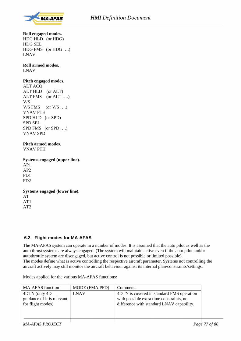
HMI Definition Document____________________________________________________________________________________________________________
____________________________________________________________________________________________________________
MA-AFAS PROJECT Page 77 of 86
Roll engaged modes.HDG HLD (or HDG)HDG SELHDG FMS (or HDG ….)LNAV
Roll armed modes.LNAV
Pitch engaged modes.ALT ACQALT HLD (or ALT)ALT FMS (or ALT ….)V/SV/S FMS (or V/S ….)VNAV PTHSPD HLD (or SPD)SPD SELSPD FMS (or SPD ….)VNAV SPD
Pitch armed modes.VNAV PTH
Systems engaged (upper line).AP1AP2FD1FD2
Systems engaged (lower line).ATAT1AT2
6.2. Flight modes for MA-AFAS
The MA-AFAS system can operate in a number of modes. It is assumed that the auto pilot as well as theauto thrust systems are always engaged. (The system will maintain active even if the auto pilot and/orautothrottle system are disengaged, but active control is not possible or limited possible).The modes define what is active controlling the respective aircraft parameter. Systems not controlling theaircraft actively may still monitor the aircraft behaviour against its internal plan/constraints/settings.
Modes applied for the various MA-AFAS functions:
MA-AFAS function MODE (FMA PFD) Comments4DTN (only 4Dguidance of it is relevantfor flight modes)
LNAV 4DTN is covered in standard FMS operationwith possible extra time constraints, nodifference with standard LNAV capability.
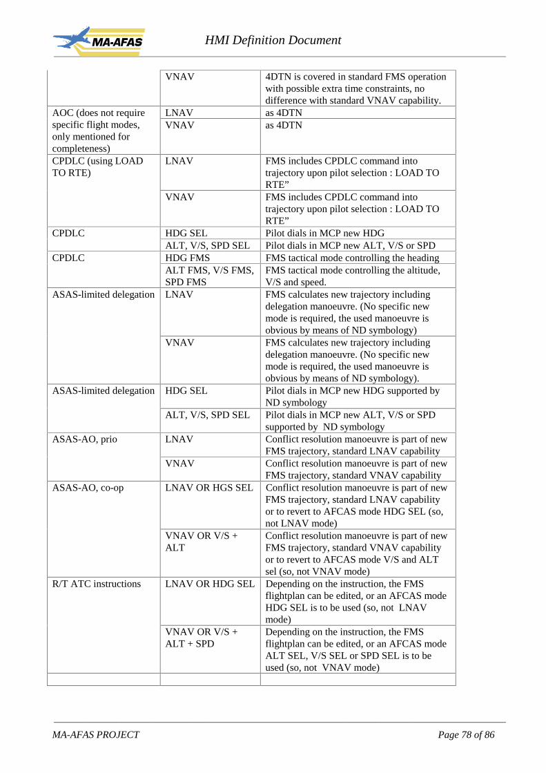
HMI Definition Document____________________________________________________________________________________________________________
____________________________________________________________________________________________________________
MA-AFAS PROJECT Page 78 of 86
VNAV 4DTN is covered in standard FMS operationwith possible extra time constraints, nodifference with standard VNAV capability.
LNAV as 4DTNAOC (does not requirespecific flight modes,only mentioned forcompleteness)
VNAV as 4DTN
LNAV FMS includes CPDLC command intotrajectory upon pilot selection : LOAD TORTE”
CPDLC (using LOADTO RTE)
VNAV FMS includes CPDLC command intotrajectory upon pilot selection : LOAD TORTE”
HDG SEL Pilot dials in MCP new HDGCPDLCALT, V/S, SPD SEL Pilot dials in MCP new ALT, V/S or SPDHDG FMS FMS tactical mode controlling the headingCPDLCALT FMS, V/S FMS,SPD FMS
FMS tactical mode controlling the altitude,V/S and speed.
LNAV FMS calculates new trajectory includingdelegation manoeuvre. (No specific newmode is required, the used manoeuvre isobvious by means of ND symbology)
ASAS-limited delegation
VNAV FMS calculates new trajectory includingdelegation manoeuvre. (No specific newmode is required, the used manoeuvre isobvious by means of ND symbology).
HDG SEL Pilot dials in MCP new HDG supported byND symbology
ASAS-limited delegation
ALT, V/S, SPD SEL Pilot dials in MCP new ALT, V/S or SPDsupported by ND symbology
LNAV Conflict resolution manoeuvre is part of newFMS trajectory, standard LNAV capability
ASAS-AO, prio
VNAV Conflict resolution manoeuvre is part of newFMS trajectory, standard VNAV capability
LNAV OR HGS SEL Conflict resolution manoeuvre is part of newFMS trajectory, standard LNAV capabilityor to revert to AFCAS mode HDG SEL (so,not LNAV mode)
ASAS-AO, co-op
VNAV OR V/S +ALT
Conflict resolution manoeuvre is part of newFMS trajectory, standard VNAV capabilityor to revert to AFCAS mode V/S and ALTsel (so, not VNAV mode)
LNAV OR HDG SEL Depending on the instruction, the FMSflightplan can be edited, or an AFCAS modeHDG SEL is to be used (so, not LNAVmode)
R/T ATC instructions
VNAV OR V/S +ALT + SPD
Depending on the instruction, the FMSflightplan can be edited, or an AFCAS modeALT SEL, V/S SEL or SPD SEL is to beused (so, not VNAV mode)
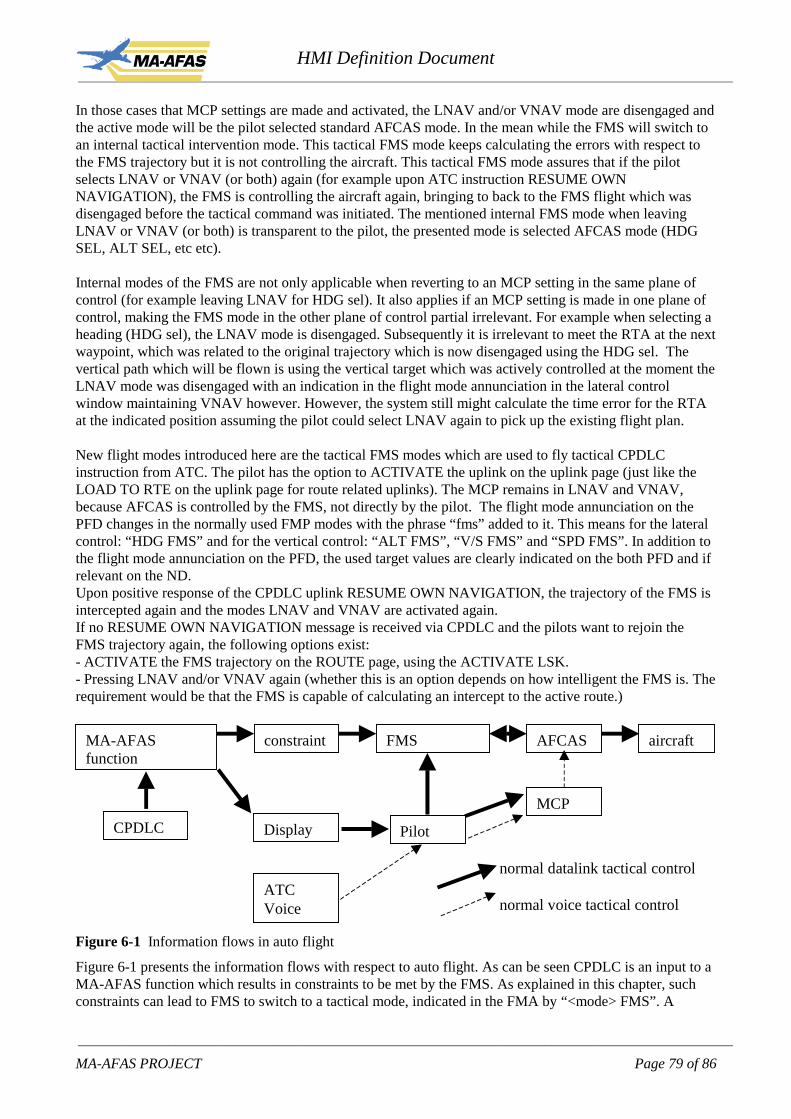
HMI Definition Document____________________________________________________________________________________________________________
____________________________________________________________________________________________________________
MA-AFAS PROJECT Page 79 of 86
In those cases that MCP settings are made and activated, the LNAV and/or VNAV mode are disengaged andthe active mode will be the pilot selected standard AFCAS mode. In the mean while the FMS will switch toan internal tactical intervention mode. This tactical FMS mode keeps calculating the errors with respect tothe FMS trajectory but it is not controlling the aircraft. This tactical FMS mode assures that if the pilotselects LNAV or VNAV (or both) again (for example upon ATC instruction RESUME OWNNAVIGATION), the FMS is controlling the aircraft again, bringing to back to the FMS flight which wasdisengaged before the tactical command was initiated. The mentioned internal FMS mode when leavingLNAV or VNAV (or both) is transparent to the pilot, the presented mode is selected AFCAS mode (HDGSEL, ALT SEL, etc etc).
Internal modes of the FMS are not only applicable when reverting to an MCP setting in the same plane ofcontrol (for example leaving LNAV for HDG sel). It also applies if an MCP setting is made in one plane ofcontrol, making the FMS mode in the other plane of control partial irrelevant. For example when selecting aheading (HDG sel), the LNAV mode is disengaged. Subsequently it is irrelevant to meet the RTA at the nextwaypoint, which was related to the original trajectory which is now disengaged using the HDG sel. Thevertical path which will be flown is using the vertical target which was actively controlled at the moment theLNAV mode was disengaged with an indication in the flight mode annunciation in the lateral controlwindow maintaining VNAV however. However, the system still might calculate the time error for the RTAat the indicated position assuming the pilot could select LNAV again to pick up the existing flight plan.
New flight modes introduced here are the tactical FMS modes which are used to fly tactical CPDLCinstruction from ATC. The pilot has the option to ACTIVATE the uplink on the uplink page (just like theLOAD TO RTE on the uplink page for route related uplinks). The MCP remains in LNAV and VNAV,because AFCAS is controlled by the FMS, not directly by the pilot. The flight mode annunciation on thePFD changes in the normally used FMP modes with the phrase “fms” added to it. This means for the lateralcontrol: “HDG FMS” and for the vertical control: “ALT FMS”, “V/S FMS” and “SPD FMS”. In addition tothe flight mode annunciation on the PFD, the used target values are clearly indicated on the both PFD and ifrelevant on the ND.Upon positive response of the CPDLC uplink RESUME OWN NAVIGATION, the trajectory of the FMS isintercepted again and the modes LNAV and VNAV are activated again.If no RESUME OWN NAVIGATION message is received via CPDLC and the pilots want to rejoin theFMS trajectory again, the following options exist:- ACTIVATE the FMS trajectory on the ROUTE page, using the ACTIVATE LSK.- Pressing LNAV and/or VNAV again (whether this is an option depends on how intelligent the FMS is. Therequirement would be that the FMS is capable of calculating an intercept to the active route.)
MA-AFASfunction
constraint FMS AFCAS aircraft
MCP
CPDLC Display Pilot
ATCVoice
normal datalink tactical control
normal voice tactical control
Figure 6-1 Information flows in auto flight
Figure 6-1 presents the information flows with respect to auto flight. As can be seen CPDLC is an input to aMA-AFAS function which results in constraints to be met by the FMS. As explained in this chapter, suchconstraints can lead to FMS to switch to a tactical mode, indicated in the FMA by “<mode> FMS”. A

HMI Definition Document____________________________________________________________________________________________________________
____________________________________________________________________________________________________________
MA-AFAS PROJECT Page 80 of 86
second issue worth indicating here is the double arrow between AFCAS and FMS. The arrow from AFCASback into the FMS stands for the EDIT modes of the FMS. (EDIT modes are not covered in the MA-AFASrequirements, but are available in some current FMSses).
7. Alerting
A number of functions of MA-AFAS require some kind of alerting. Various levels of alerting will beapplied consisting of aural alerts, visual alerts with dedicated alert lights and visual alerts on the displaydevice on which the function is operated on.
The tables below present a general alerting scheme for system alerts, flight alerts and communication alerts.This alerting scheme is based on existing system alerting schemes.
System alerting scheme
Level Characteristics Aural Alert lights Visual display3 Immediate
actionRepetitive triplechime
Master warning,red
MFD messagein red
2 Immediateawareness
Dual chime Master caution,amber
MFD messagein amber
1 Awareness Single chime - MFD messagein amber
0 Memo - - MFD messagein white
Flight alerting scheme
Level Characteristics Aural Alert lights Visual display3 Immediate
actionSpeech - PFD/ND, red
2 Immediateawareness
Dual beep - ND, amber
1 Awareness Single beep - ND, amber/yellow
0 Memo - - ND, green
Communication alerting scheme
Level Characteristics Aural Alert lights Visual display3 Immediate
actionSpeech (R/T) - -
2 Immediateawareness
Dual ping Data link, cyan -
1 Awareness Single ping Data link, cyan -0 Memo - Data link, cyan -
However, alerting should be integrated in the existing alerting scheme of the cockpit in which the MA-AFAS system is to be applied.

HMI Definition Document____________________________________________________________________________________________________________
____________________________________________________________________________________________________________
MA-AFAS PROJECT Page 81 of 86
The table below indicates the events which require an alert together with a recommendation for visualand/or aural alerts based on the general alerting scheme. These should be regarded as guidelines and mayneed to be adapted to fit in the abilities and existing alerting scheme of the respective retrofit cockpit.
Function Alert condition Alert visual Alert auralASAS-AO Conflict detected > 6 min and prio ND NillASAS-AO Conflict detected > 6 min and no
prioND Single beep
ASAS-AO Conflict detected > 3 min, <6 min ND Single beep
ASAS-AO Conflict detected < 3 min ND Dual beep
ASAS-AO Time to conflict falls below 5 min(with detection > 5 min and prio)
ND Single beep
ASAS-AO Time to conflict falls below 5 min(detection > 5 min and no prio)
ND Nill
ASAS-AO Time to conflict falls below 3 min(detection > 3 min)
ND Dual beep
ASAS-AO Separation violated ND “SEPARATION,SEPARATION”
ASAS spacing Distance/time spacing near lowerspacing threshold � falls belowlower value defined to achieverequired spacing 95% of the time.
NDflashing deviationpointer
Dual beep
ASAS spacing Distance/time spacing near upperspacing threshold � exceedsupper value defined to achieverequired spacing 95% of the time.
NDflashing deviationpointer
Dual beep
ASAS spacing Distance/time spacing falls belowlower spacing threshold (=instructed value)
NDflashing deviationpointer and scale
“TOO CLOSESPACING, TOOCLOSESPACING”
ASAS spacing Distance/time spacing exceedsupper spacing threshold
NDflashing deviationpointer and scale
“SPACING,SPACING”
CPDLC Uplink received, alert attributeHigh
Steady cyanglareshielddatalink light
Dual ping
CPDLC Uplink received, alert attributeMedium
Steady cyanglareshielddatalink light
Single ping
CPDLC Uplink received, alert attributeLow
Steady cyanglareshielddatalink light
Nill

HMI Definition Document____________________________________________________________________________________________________________
____________________________________________________________________________________________________________
MA-AFAS PROJECT Page 82 of 86
4DTN Uplink received Steady cyanglareshielddatalink light
Single ping
FIS & AOC Uplink received Steady cyanglareshielddatalink light
Nill

HMI Definition Document____________________________________________________________________________________________________________
____________________________________________________________________________________________________________
MA-AFAS PROJECT Page 83 of 86
Abbreviations
4D Four Dimension4DTN 4D Trajectory Negotiation
A/C AircraftACAS Airborne Collision Avoidance SystemACQ AcquireADS Automatic Dependent SurveillanceADS-B ADS - BroadcastALT AltitudeAO Autonomous OperationsAOC Airline Operations CentreA-OPS Autonomous OperationsAP Auto PilotAPP ApproachARPT AirportASAS Airborne Separation Assurance SystemAT Auto ThrottleATC Air Traffic ControlATIS Automatic Terminal Information ServiceAT LST At LeastATM Air Traffic ManagementAUTO-OPS Autonomous Operations
BICCA Bevonius ICAO Code Conversion Algorithm
CCD Cursor Control DeviceCDTI Cockpit Display of Traffic InformationCG Center of GravityCLB ClimbCNCL CancelCPA Closest Point of ApproachCPDLC Controller Pilot Data Link CommunicationCRZ CruiseCTR Centered
DCP Display Control Paneldeg degreeDEP DepartureDES DescentDESEL DeselectDIR TO Direct ToDIST DistanceD/L Data LinkDLINK Data LinkDME Distance Measuring Equipment
EOBT Estimated Off Block TimeETA Estimated Time of Arrival

HMI Definition Document____________________________________________________________________________________________________________
____________________________________________________________________________________________________________
MA-AFAS PROJECT Page 84 of 86
EXEC Execute
FD Flight DirectorFFAS Free Flight AirspaceFID Flight IdentificationFIS Flight Information ServiceFL Flight LevelFLT FlightFMA Flight Mode AnnunciationFMS Flight Management SystemF-PLN Flight Planfpm feet per minuteft feet
GBAS Ground Based Augmentation SystemGNSS Global Navigation Satellite SystemGS Groundspeed
HDG HeadingHLD HoldHMI Human Machine Interface
IAS Indicated AirspeedICAO International Civil Aviation OrganisationID IdentificationIFTM In Flight Traffic ManagementILS Instrument Landing SystemINIT Initial, Initialisation
KG Kilogramkts knots
LAT LateralLNAV Lateral NavigationLSK Line Select Key
M Mach numberMA-AFAS The More Autonomous – Aircraft in the Future Air
Traffic Management SystemMAG MagneticMAS Managed AirspaceMCDU Multi-purpose Control and Display UnitMCP Mode Control PanelMETAR Meteorological Aviation Routine Weather ReportMFD Multi Function Displaymin minuteMSG Message
N/A Not ApplicableND Navigation DisplayNDB Non Directional BeaconNEG NegativeNm, NM Nautical Mile

HMI Definition Document____________________________________________________________________________________________________________
____________________________________________________________________________________________________________
MA-AFAS PROJECT Page 85 of 86
PAZ Protected Airspace ZonePETAL Preliminary Eurocontrol Test of Air-Ground Data
LinkPF Pilot FlyingPFD Primary Flight DisplayPNF Pilot Not FlyingPREV PreviousPROF ProfilePTH Path
RCL RecallREF ReferenceREQ RequestR/T Radio TelephonyRTA Required Time of ArrivalRTE RouteRVR Runway Visual Range
S SecondSARP Standards and Recommended PracticesSBAS Satellite Based Augmentation SystemSDEV Spacing Deviationsec secondSEL SelectSEP SeparationSIGMET Significant MeteoSPD SpeedSTA StationSTBY StandbySTD Standard
TAF Terminal Area ForecastTAS True AirspeedTFC TrafficTMA Terminal Manoeuvring AreaTOW Take-Off WeightTWY Taxiway
VDEV Vertical DeviationVERT VerticalVHF Very High FrequencyVNAV Vertical NavigationVOR VHF Omni-directional RangeV/S Vertical Speed
WILCO Will ComplyWPT Waypoint
X-MAX Crossing MaximumX-MIM Crossing Minimum
ZFW Zero Fuel Weight

HMI Definition Document____________________________________________________________________________________________________________
____________________________________________________________________________________________________________
MA-AFAS PROJECT Page 86 of 86


![CARE ASAS Action The Application of the Validation ... · [1] ASAS Activity 2 Report: Towards a validation framework for ASAS applications ASAS Activity 2 Report Edition 1.0 12 June](https://static.fdocuments.in/doc/165x107/5c2c460c09d3f212718cf777/care-asas-action-the-application-of-the-validation-1-asas-activity-2-report.jpg)


