
D4.1.1 Satellite Network Mission Requirements - … · Satellite Network Mission Requirements ......
166
BATS (317533) D4.1.1 D4.1.1 Satellite Network Mission Requirements Instrument Collaborative Project Topic ICT-2011.1.1 Project Title Broadband Access via Integrated Terrestrial & Satellite Systems Project Number 317533 Project Acronym BATS Contractual Delivery Date M4 Actual Delivery Date 04/04/2013 Contributing WP WP4 Project Start Date 01/10/2012 Project Duration 36 months Dissemination Level RE Editor AVA Contributors AVA, AST and TAS-F
Transcript of D4.1.1 Satellite Network Mission Requirements - … · Satellite Network Mission Requirements ......

BATS (317533) D4.1.1
D4.1.1
Satellite Network Mission Requirements
Instrument Collaborative Project
Topic ICT-2011.1.1
Project Title Broadband Access via Integrated Terrestrial & Satellite Systems
Project Number 317533
Project Acronym BATS
Contractual Delivery Date M4
Actual Delivery Date 04/04/2013
Contributing WP WP4
Project Start Date 01/10/2012
Project Duration 36 months
Dissemination Level RE
Editor AVA
Contributors AVA, AST and TAS-F
BATS (317533) D4.1.1
04/04/2013 i
Disclaimer
This document reflects the contribution of the participants of the research project BATS. The European Union and its agencies are not liable or otherwise responsible for the contents of this document; its content reflects the view of its authors only. This document is provided without any warranty and does not constitute any commitment by any participant as to its content, and specifically excludes any warranty of correctness or fitness for a particular purpose. The user will use this document at the user's sole risk.
BATS (317533) D4.1.1
04/04/2013 ii
Document History
Version Date Modifications Source
0.0 15/01/13 Creation of document AVA
0.1 08/03/13 Final draft submitted to QAT AVA
0.2 03/04/13 Final draft with QA amendments AVA
1.0 04/04/13 Final version issued to EC. AVA
Contributors
Name Company Contribution
Javier Pérez Trufero AVA All document
Simon Watts AVA All document
Cassie Lee AVA Chapter 11
Thierry Fesquet AST Chapters 4, 5, 6, 9 and 10
Cyrille Moreau AST Chapters 4, 5, 6, 9 and 10
Bernard Roy AST Chapters 4, 5, 6, 9 and 10
Mathieu Dervin TAS-F Chapters 4, 5, 6 and 9

BATS (317533) D4.1.1
04/04/2013 iii
Table of Contents
List of Figures ......................................................................................................................... v
List of Tables ........................................................................................................................ vii
List of Acronyms .................................................................................................................. viii
Executive Summary .............................................................................................................12
1 Introduction ...................................................................................................................13
1.1 Scope of the document ..........................................................................................13
1.2 Formalisation Methodology ....................................................................................13
2 Mission Definition ..........................................................................................................16
2.1 Mission and Deployment Concept ..........................................................................16
2.2 Scenarios Definition ...............................................................................................17
2.2.1 Network architecture for Q/V-band feeder link scenarios .................................17
2.2.2 Network architecture for Optical feeder link scenarios .....................................18
2.3 Mission trade-offs ...................................................................................................20
3 Service Requirements ...................................................................................................22
4 System Requirements ...................................................................................................28
5 Space Segment Requirements ......................................................................................35
5.1 Common requirement for both 2020 and 2025 S/C’s ..............................................35
5.1.1 Satellite ...........................................................................................................35
5.1.2 Payload ...........................................................................................................36
5.2 Space Segment Requirements for 2020 timeframe ................................................42
5.2.1 Satellite ...........................................................................................................42
5.2.2 Platform ...........................................................................................................42
5.2.3 Payload ...........................................................................................................42
5.3 Space Segment Requirements for 2025 timeframe ................................................46
5.3.1 Satellite ...........................................................................................................47
5.3.2 Platform ...........................................................................................................47
5.3.3 Payload ...........................................................................................................48
6 Gateway Requirements .................................................................................................50
6.1 Q/V Gateway ..........................................................................................................50
6.2 Optical Gateway .....................................................................................................52
7 User Terminal Requirements .........................................................................................55
7.1 Cost Requirements.................................................................................................55
7.1.1 Equipment .......................................................................................................55
7.1.2 Installation .......................................................................................................55

BATS (317533) D4.1.1
04/04/2013 iv
7.2 Performance requirements .....................................................................................57
7.2.1 Air Interface .....................................................................................................58
7.3 Power consumption ................................................................................................59
7.4 UT Regulatory Conformance ..................................................................................60
8 NCC/NMS Requirements ..............................................................................................61
9 Identification of Platform ................................................................................................65
9.1 Performances in 2020 ............................................................................................65
9.2 Performances in 2025 ............................................................................................68
10 Regulatory Requirements ..........................................................................................70
10.1 Ka Band .................................................................................................................70
10.2 Q/V Band ...............................................................................................................71
10.3 Optical Communications ........................................................................................72
10.4 Summary ................................................................................................................72
11 Deployment Requirements.........................................................................................74
12 References ................................................................................................................80
Annex A - Complete List of Requirements (Assembled) ..................................................81
Annex B - Air Interface Performances ............................................................................ 108
Annex C - Telecom System Analysis for Multicast Support ............................................ 114
Annex D - Beam Layout Examples ................................................................................ 120
Annex E - Post-launch flexibility: some options (2025 timeframe) .................................. 123
Annex F - Identification of Platform ................................................................................ 129
Annex G - Regulatory Analysis....................................................................................... 133

BATS (317533) D4.1.1
04/04/2013 v
List of Figures
Figure 2-1: BATS Satellite System Deployment Concept. ....................................................17
Figure 2-2: Satellite network architecture for scenarios based on Q/V-band feeder links ......19
Figure 2-3: Satellite network architecture for scenarios based on Optical feeder links. .........20
Figure 3-1: Total BATS satellite market traffic predicted per country for 2020. .....................25
Figure 3-2: Illustrating capacity versus demand over time. ...................................................26
Figure 3-3: Total predicted multicast traffic for 2020 [3]. .......................................................27
Figure 4-1: Frequency plan for multicast traffic. ....................................................................34
Figure 5-1: CDF of Minimum EIRP Density over the Service Area .......................................37
Figure 5-2: Map of Minimum EIRP Density over the Service Area ........................................37
Figure 5-3 : Spectrum allocated to FSS in V-Band, to be considered for the FWD uplink .....40
Figure 5-4 : Spectrum allocated to FSS in Q-Band, to be considered for the RTN downlink .41
Figure 5-5: FWD Downlink Frequency Plan. .........................................................................44
Figure 5-6: RTN Uplink Frequency Plan ...............................................................................45
Figure 6-1 Antenna pattern for a 5m antenna in Q/V band ...................................................52
Figure 6-2: Figure 6 2: Antenna pattern for an 8m antenna in Q/V band. ..............................52
Figure 9-1: Payload envelope evolutions. .............................................................................65
Figure 9-2: @Bus payload envelope. ....................................................................................66
Figure 9-3: Examples of payload accommodations. .............................................................67
Figure 9-4: Payload domain with respect to launchers. .........................................................67
Figure 9-5: EOR benefits with 2020 engines. .......................................................................68
Figure 9-6: EOR benefits with 2025 engine. .........................................................................69
Figure 10-1: CEPT segmentation of the uplink bands from 27.5 to 31.0 GHz .......................71
Figure 10-2: CEPT segmentation of the downlink bands from 17.7 to 21.2 GHz...................71
Figure 10-3: CEPT sharing of the Q/V band (uplink) from 42.5 to 51.4 GHz. ........................72
Figure 10-4: CEPT sharing of the Q/V band (downlink) from 37.5 to 42.5 GHz.....................72
Figure B-12-1: C/Im vs. OBO for 6 carriers. ........................................................................ 110
Figure C-12-2: Example of linguistic beam coverage. ......................................................... 114
Figure C-12-3: Example of frequency band to be used for the transmission of the multicast traffic in the case of a dedicated satellite payload solution. ................................................. 115
Figure C-12-4: Frequency plan example with multicast traffic transmitted in each carrier of each user spot beam. ......................................................................................................... 116
Figure C-12-5: Frequency plan example with multicast traffic transmitted in only one carrier of each user spot beam. ..................................................................................................... 117
Figure C-12-6: Multicast traffic demand per user spot beam (based on beam layout of Terabit study). ................................................................................................................................ 118
Figure D-12-7: 252 beams of 0.23°..................................................................................... 120

BATS (317533) D4.1.1
04/04/2013 vi
Figure D-12-8: 272 beams of 0.22°..................................................................................... 120
Figure D-12-9: 295 beams of 0.21°..................................................................................... 121
Figure D-12-10: 319 beams of 0.20°. .................................................................................. 121
Figure D-12-11: Relation between size and number of beams. .......................................... 122
Figure E-12-12: on-board selectivity (example with 50% active beams and 4 colors). ........ 124
Figure E-12-13: Selective frequency band allocation – Example 1 ..................................... 124
Figure E-12-14: Selective frequency band allocation – Example 2 ..................................... 125
Figure E-12-15: Steerable spot ........................................................................................... 125
Figure E-12-16: beam hopping with two spots per polarization, served by the same gateway ........................................................................................................................................... 126
Figure E-12-17: Beam hopping – time allocation example. ................................................. 126
Figure E-12-18: Unequal power allocation – example with two clusters of 4 spots and 4-color reuse scheme. .................................................................................................................... 127
Figure E-12-19: Example with digital transparent processing and flexible per spot band allocation. ........................................................................................................................... 127
Figure F-12-20: Payload envelope evolutions. .................................................................... 129
Figure F-12-21: Examples of payload accommodations. .................................................... 130
Figure G-12-22: The ITU Regions distribution. ................................................................... 134
Figure G-12-23: Power flux-density limits in the shared Ka-band. ...................................... 136
Figure G-12-24: Implementation of Decision ERC/DEC/(00)07 .......................................... 139
Figure G-12-25: Implementation of Decision ECC/DEC/(05)01 .......................................... 140
Figure G-12-26: Implementation of Decision ECC/DEC/(06)02 .......................................... 141
Figure G-12-27: Implementation of Decision ECC/DEC/(06)03 .......................................... 142
Figure G-12-28: CEPT segmentation of the uplink bands from 27.5 to 31.0 GHz ............... 145
Figure G-12-29: CEPT segmentation of the uplink bands from 17.7 to 21.2 GHz ............... 145
Figure G-12-30: FSS/BSS pairing in Ka band. .................................................................... 147
Figure G-12-31: power flux-density limits in the 21.4-22.0 GHz band. ................................ 148
Figure G-12-32: power flux-density limits in the 21.4-22.0 GHz band for coordination. ....... 150
Figure G-12-33: PFD limits in Q/V band. ............................................................................ 157
Figure G-12-34: Location of the radio astronomy stations referred in Table 14 ................... 159
Figure G-12-35: Implementation of decision ERC/DEC/(00)02 ........................................... 162
Figure G-12-36: Implementation of decision ECC/DEC/(02)04 ........................................... 163
Figure G-12-37 : CEPT sharing of the Q/V band (uplink) from 42.5 to 51.4 GHz ................ 163
Figure G-12-38 : CEPT sharing of the Q/V band (downlink) from 37.5 to 42.5 GHz ............ 164

BATS (317533) D4.1.1
04/04/2013 vii
List of Tables
Table 1-1: Summary of requirement formalisation methodology. ..........................................15
Table 4-1: FWD Link Air Interface Performances in Clear Sky ..............................................31
Table 4-2: RTN Link Air Interface Performances in Clear Sky ..............................................32
Table 10-1: Summary of Regulatory requirements. ..............................................................73
Table B-12-1: FWD Link Air Interface Performances in Clear Sky. ..................................... 112
Table B-12-2: RTN Link Air Interface Performances in Clear Sky. ...................................... 113
Table C-12-3: Summary table of solutions for multicast support. ........................................ 119
Table D-12-4: Summary of the relation between size and number of beams. ..................... 122
Table E-12-5: Comparison of the post-flexibility options (single satellite scenario, forward link). ................................................................................................................................... 128
Table G-12-6: Allocation to services in the 17.7-19.7 GHz band according to the ITU. ....... 135
Table G-12-7: Allocation to services in the 27.5-29.5 GHz band according to the ITU. ....... 135
Table G-12-8: Power flux-density limits in the shared Ka-band. .......................................... 136
Table G-12-9: Frequency bands used by the IRIDIUM constellation. .................................. 143
Table G-12-10: List of IRIDIUM’s gateways declared outside of the United States of America. ........................................................................................................................................... 144
Table G-12-11: Service allocations according to the ITU in the band 17.3-17.7 GHz. ......... 146
Table G-12-12: Service allocations according to the ITU in the band 24.65-25.25 GHz. ..... 147
Table G-12-13: Power-flux density limits in the 21.4-22 GHz band from Table 21-4 of Article 21. ...................................................................................................................................... 147
Table G-12-14: Technical conditions for coordination from Table 5-1 of Appendix 5. ......... 149
Table G-12-15: Service allocations in Q/V band (downlink). ............................................... 154
Table G-12-16: Service allocations in Q/V band (uplink). .................................................... 155
Table G-12-17: Applicable power flux-density limits. .......................................................... 156
Table G-12-18: List of stations operating in the Radio Astronomy Service. ......................... 158
Table G-12-19: Frequency bands registered for radio astronomy stations operation. ......... 159
Table G-12-20: Power limits to respect in the 49.7-50.2 GHz band. ................................... 160
Table G-12-21: Power limits to respect in the 50.4-50.9 GHz band. ................................... 161
Table G-12-22: Regulatory sum up. .................................................................................... 165

BATS (317533) D4.1.1
04/04/2013 viii
List of Acronyms
ALC Automatic Level Control
ACM Adaptive Coding and Modulation
ANSI American National Standards Institute
BATS Broadband Access via Integrated Terrestrial & Satellite Systems
BSS Broadcasting Satellite Service
CAGR Compound Annual Growth Rate
CEN Comity of Normalization
CEPT European Conference of Postal and Telecommunications Administrations
C/I Carrier over interference ratio
DC Direct Current
DTH Direct-to-Home
ECC European Communications Committee
EESS Earth Exploration Satellite Service
EIRP Equivalent Isotropically Radiated Power
EMP Maximal Permit Exposure
EOR Electrical Orbital Rising
ERC European Radiocommunications Committee
ESA European Space Agency
FCC Federal Communication Commission
FGM Fixed Gain Mode
F/L Forward Link
FS Fixed Service
FSS Fixed Satellite Service
FWD Forward
GEO Geostationary orbit (1)
GNI Gross National Income
GPS Global Positioning System
GSO Geostationary Orbit (2)
G/T Gain over noise Temperature
GTO Geostationary Transfer Orbit

BATS (317533) D4.1.1
04/04/2013 ix
GW Gateway
HD High Definition
HDFSS High Density Application for Fixed Satellite Service
HPA High Power Amplifier
HTS High Throughput Satellite
ICNIRP International Commission on Non-Ionizing Radiation Protection
IoT Internet of Things
IP Internet Protocol
ISO International Organization for Standardization
ISP Internet Service Provider
ITU International Telecommunication Union
IUG Intelligent User Gateway
LHCP Left Hand Circular Polarization
LNA Low-noise Amplifier
MS Mobile Service
MTBF Mean Time Between Failures
NATO North Atlantic Treaty Organization
NCC Network Control Centre
NGSO Non Geostationary Orbit
NMS Network Management System
OGW Optical Gateway
OTT Over-The-Top
P2P Peer-2-Peer
P/L Payload
QoE Quality of Experience
QoS Quality of Service
RF Radio Frequency
RHCP Right Hand Circular Polarization
R/L Return Link
RTN Return
S/C Spacecraft
SCC Satellite Control Centre

BATS (317533) D4.1.1
04/04/2013 x
SSPA Solid State Power Amplifier
SR Space Research
TTC Telemetry Tracking and Control
TV Television
TWT Travelling Wave Tube
UB User Beam
ULPC Uplink Power Control
UT User Terminal
VoD Video on Demand
VSAT Very Small Aperture Terminal
WP Workpackage

BATS (317533) D4.1.1
04/04/2013 xi
Intentionally blank

BATS (317533) D4.1.1
04/04/2013 12
Executive Summary
This deliverable defines the overall mission requirements for the satellite network configurations to be designed in the following activities of this workpackage (SWP4.2, SWP4.3, SWP4.4, SWP4.5 and SWP4.6). Specifically this document aims to define:
Satellite network mission and service requirements;
Space segment requirements;
SatCom user terminal and gateway requirements;
Network Control/Management Centre requirements;
Analysis of the ITU and national regulatory requirements for the frequency plan;
Deployment requirements;
Identification of a reference state-of-the-art platform by the 2020 timeframe.
This document takes as inputs the deliverables “D2.1 – Definition of Broadband Services Requirements and Quality of Experience” which describes the Quality of Service (QoS) requirements of the broadband services and applications envisaged by 2020, and “D2.2 – Broadband Technologies, Capabilities & Challenges” which determines how the technology for satellite broadband delivery will evolve and be rolled out up to 2020. D2.2 also provides a first estimate of the addressable market for a BATS-like service and the amount of traffic to be delivered by the satellite network in 2020. This document also builds upon the Terabit/s ESA studies identifying the space segment technologies for next generation High Throughput Satellite (HTS) systems. In addition, the ESA study “Techniques and technologies for ultra high throughput multi-spot beam networks (MSBN)” is also used as reference for the definition of the ground segment requirements.
As predicted in D2.2, in order to serve the unserved and underserved areas of Europe in terms of superfast broadband by 2020, the satellite network will need to deliver approximately 3.8 Tbps. Such figure is nearly 4 times the targeted Terabit/s satellite throughput, meaning that innovative constellations, technologies and techniques will need to be considered and analysed to better fit the volume and distribution of the broadband traffic. In the framework of the BATS project, two different configurations for the feeder link will be studied both considering a move towards higher frequency bands (Q/V and Optical) where more spectrum is available. In addition, two different spacecraft options will be designed: a baseline configuration aiming to homogeneously maximize the overall system capacity and which launch is envisaged by 2020, and an enhanced spacecraft with the goal of bringing additional capacity to the areas with higher demand and which will consider more innovative technologies to be available by 2025 and above. The enhanced spacecraft will include as well some degree of post-launch flexibility in order to be able to adapt its service to the evolution of the traffic demand over time. A constellation based on these two types of satellites will allow the BATS service to deliver in a flexible manner a high system capacity in the whole coverage area. Moreover, in order to reflect the increasing consumption of video content and the current migration of linear TV towards over-the-top delivery, both spacecraft options will support the transmission of multicast traffic over the total coverage.
In conclusion, this documents aims to be a common reference for all the different activities throughout the BATS project looking at the design and dimensioning of the BATS satellite system and the related radio interfaces.

BATS (317533) D4.1.1
04/04/2013 13
1 Introduction
1.1 Scope of the document The scope of this document is to define and compile the overall mission requirements for the BATS satellite network by 2020 and above, considering both Q/V-band and Optical feeder link configurations. This document is divided into different chapters which separately identify the specific requirements for the different entities and functionalities of the end-to-end satellite communication system including the space segment, the gateways and the user terminals. This document has built upon the mission requirements of ESA studies identifying the space and ground segment technologies for next generation High Throughput Satellite (HTS) systems.
This deliverable will be then fed into the following tasks within WP4, where the satellite network architecture will be defined and characterised in detail, the different options for the feeder link configuration will be studied, and novel Radio Interface and Interference and Radio Resource Management systems will be investigated. The requirements defined in this document will be also taken into account in WP3.2 where the integration of the satellite and terrestrial access networks is to be assessed, and in WP3.4 where the Intelligent User Gateway architecture is to be described in detail.
This document is organised as follows; Section 2 defines the mission concept and the scenarios, and details the different network architectures to be considered. Section 3 specifies the service requirements starting with the initial system dimensioning and QoS requirements. Section 4 continues with the definition of the system requirements, including the definition of the coverage and the orbital location of the satellites. The document continues with Section 5, where the requirements of the Space Segment are specified. The following sections 6, 7 and 8 look at the ground segment requirements looking respectively at the gateway, user terminal and NCC/NMS. Section 9 looks at which platforms to be considered in the different scenarios and Section 10 lists the regulatory requirements for the considered frequency bands. Finally, Section 11 proposes the service design and implementation time schedule for the phases currently defined for the BATS satellite network. To conclude, all the requirements have been compiled together in Annex A - to ease their reference in the next steps of the satellite network design and dimensioning. In addition, Annex B - provides additional information on the considered air interfaces, Annex C - includes the analysis on the way the satellite system should handle the multicast traffic, Annex D - provides an example of user beam layouts over the total coverage, Annex E - includes the initial analysis of post-launch flexibility techniques for the 2025 timeframe, Annex F - gives additional detail on the forecasted satellite platforms and their capabilities and Annex F - provides a detailed study of the radio regulations of the Ka and Q/V frequency bands.
1.2 Formalisation Methodology Throughout this document the reader will encounter all the individual requirements that will be used as a baseline in the following activities of the project. Each requirement is formalized with a unique ID that is compiled by 5 parts as follows:
ID: ACT-TYP-SC-FEED-NUM
where
ACT identifies the name of the activity, in this report BATS for Broadband Access via integrated Terrestrial and Satellite systems.
TYP provides the type of requirement and could get the following values: SER for service requirements, SYS for system requirements, SAT for space segment requirements, GW for gateway requirements, UT for user terminal, PLAT for platform

BATS (317533) D4.1.1
04/04/2013 14
requirements, NCM for network control and management, REG for regulatory, and DEP for deployment requirements.
SC specifies the type of scenario that the requirement refers to. It could obtain the following values BL for the baseline configuration (2020), EH for the enhanced configuration (2025) and ALL for both configurations.
FEED specifies the frequency band of the feeder link in the corresponding scenario. It could obtain the values QV for the Q/V-band feeder link configuration, OPT for the optical frequency feeder link configuration, and ALL for both configurations.
NUM is just an increasing number of 3 digits to ensure the particularity of the requirement.
All requirements shall be understood based on the following rule:
The word shall is used to indicate mandatory requirements strictly to be followed in order to conform to the requirements and from which no deviation is permitted (shall equals is required to).
The word should is used to indicate that among several possibilities one is recommended as particularly suitable, without mentioning or excluding others; or that a certain course of action is preferred but not necessarily required; or that (in the negative form) a certain course of action is deprecated but not prohibited (should equals is recommended that).
The word may is used to indicate a course of action permissible within the limits of the standard (may equals is permitted).
The word can is used for statements of possibility and capability, whether material, physical, or causal (can equals is able to).

BATS (317533) D4.1.1
04/04/2013 15
Table 1-1: Summary of requirement formalisation methodology.
ID part Option
ACT BATS
TYP
SER Service requirements
SYS System requirements
SAT Space segment requirements
GW Gateway requirements
UT User terminal requirements
PLAT Platform requirements
NCM Network control and management centre requirements
REG Regulatory requirements
DEP Deployment requirements
SC
BL Baseline spacecraft (2020)
EH Enhanced spacecraft (2025)
ALL Both spacecraft
FEED
QV Q/V-band feeder link
OPT Optical feeder link
ALL Both options
NUM 3 digits number ensuring the particularity of the requirement

BATS (317533) D4.1.1
04/04/2013 16
2 Mission Definition
This chapter describes the mission concept and scenarios that will be considered throughout the activities related to the satellite network architecture in the framework of the BATS project. The requirements described in this deliverable are based on the system deployment concept and high-level network architectures defined in this chapter.
2.1 Mission and Deployment Concept Due not only to an increase in number of broadband subscribers, mainly driven by increasing broadband penetration rates and service take-up across the European countries, but also to a shift towards more bandwidth demanding applications and services during the coming years; the traffic demand for satellite broadband is expected to grow a 6 fold by 2020. In order to be able to serve this increasing demand, next generation High Throughput Satellites (HTS) will need to be able to offer both higher throughput and higher data rates, flexibility to adapt to traffic demand across the coverage area, and at the same time decrease the cost per transmitted bit. In addition, the appearance of the BATS Intelligent User Gateway (IUG) in the market is expected to ramp up the increase of traffic demand for satellite broadband as it will be addressed not only to areas without any kind of terrestrial broadband coverage, but also to areas in which the required data rates and availability will only be met by the integration of satellite and terrestrial networks.
The BATS mission will focus on the design of an end-to-end satellite system, possibly comprising a constellation of several satellites, with the main objective of minimising the end-user service price while allowing the system to have enough flexibility to adapt to the evolution of the traffic demand during the system lifetime. Hence, the BATS mission differs substantially with the ESA Terabit/s studies where the main objective was to identify the key technologies and techniques at payload and platform levels for being able to maximize by 2020 the satellite system throughput up to 1 Terabit/s.
Rather than based on a “big bang” approach, the BATS constellation will build up the capacity in-orbit in a progressive way with the launch of several HTS in different phases between 2020 and 2030. The first satellites will be launched in 2020 and will be based on a baseline design configuration considering a realistic approach and technologies expected to be available by that timeframe. In 2025, an enhanced type of satellite will be ready for launch in order to bring additional capacity to hot-spots and hence optimise the constellation throughput on the evolution of the traffic demand across the coverage area. The enhanced configuration will be based on a more optimistic approach including several innovative technologies such as flexibility in terms of bandwidth and power across the different spot-beams in both the spatial and time domains.
Figure 2-1 illustrates in a high level the aforementioned deployment concept. The horizontal axis represents time and the vertical axis represents in-orbit capacity. The blue continuous line illustrates the expected traffic demand without the existence of the BATS concept whereas the blue dashed line represents the available capacity in-orbit; note that each step in this line means the launch of a new broadband satellite which does not belong to the BATS system. On the other hand, the continuous orange line illustrates the expected acceleration of the traffic demand when the appearance of the BATS IUG takes place. Finally, the dashed orange line shows the additional in-orbit capacity that the BATS satellites will progressively bring to follow the evolution of the traffic demand over time. The broad orange arrows indicating BATS # represent possible launch dates of BATS satellites.

BATS (317533) D4.1.1
04/04/2013 17
2.2 Scenarios Definition As aforementioned, the BATS satellite system will be based on two different types of spacecraft. The first type of BATS satellites (i.e., baseline configuration) will consider only technologies expected to be available for launch by 2020 and realistic figures regarding the evolution of state of the art platforms. The second kind of satellites (i.e., enhanced configuration) will be based on more innovative techniques and optimistic figures regarding the evolution of satellite systems and communication technologies. The purpose of such satellites will be to bring additional capacity to the hot-spots and provide the capability to the system to follow the evolution of the traffic demand over time. During the course of the BATS project, the two configurations will be designed based on both Q/V-band and Optical feeder link options. Therefore, the following four different scenarios will be considered:
Scenario 1: Baseline configuration based on Q/V-band feeder links.
Scenario 2: Baseline configuration based on Optical feeder links.
Scenario 3: Enhanced configuration based on Q/V-band feeder links.
Scenario 4: Enhanced configuration based on Optical feeder links.
In the following subsections of this chapter we describe the network architecture for both the Q/V-band and Optical feeder link options that will be assumed during the BATS project.
2.2.1 Network architecture for Q/V-band feeder link scenarios
The satellite access network based on Q/V band feeder links is composed of the following parts:
A space segment composed of one or more satellites in geostationary orbit. The satellite connects the GWs of the ground segment to the user terminals, thanks to a set of feeder and user beams.
Figure 2-1: BATS Satellite System Deployment Concept.

BATS (317533) D4.1.1
04/04/2013 18
A ground segment which includes:
o A main Network Control Centre (NCC) which has the responsibility to control and synchronise the overall network.
o A main Network Management System (NMS) which handles the management of the resources in the network.
o A Satellite Control Centre (SCC) which aims at monitoring and controlling the space segment.
o A Telemetry Tracking and Control (TTC) station to transmit and receive information to or from the space segment.
o A set of GWs operating in Q/V-band which are in charge of transmitting and receiving data, control and management traffic to or from the user terminals. Each GW is equipped with their own local NCC/NMS to ensure their individuality and their operation sequence in case of a total system malfunction originating from a main NCC/NMS failure.
A user segment which is composed of a set of user terminals operating in Ka-band. The satellite user terminal, depending on the integration scenario defined in WP2.4, is connected to or integrated in the BATS IUG and hence it is also connected to a local area network in order to deliver the useful traffic to the end user.
Figure 2-2 illustrates the aforementioned overall satellite system architecture for the scenarios based on Q/V-band feeder links. Note that a backbone network, which is not part of the access network, is in charge of interconnecting the SCC, NCC/NMS, GWs, TTC and the Internet Service Providers (ISPs), namely to provide a way to exchange data, and manage and control the traffic. The main NCC/NMS is connected in a star topology with all feeder link components except the TT&C station, which is controlled only by the SCC. This example shows a mesh topology network between the GWs, which is consider just as an optional configuration. The fact of interconnecting the different GW sites will allow a faster switching between these sites in case of a severe fading or malfunction, but will increase as well the complexity and cost of the system, especially if the gateways are located considerably far away. The decision regarding the interconnection of the different GWs is subject to future trade-offs.
2.2.2 Network architecture for Optical feeder link scenarios
The major difference with the architecture presented in Section 2.2.1 is the usage of optical ground stations instead of Q/V-band gateways in the feeder link. Hence, the satellite access network is composed of the following units:
A space segment composed of one or more satellites in geostationary orbit. The satellite connects the optical telescopes of the ground segment to the Ka-band user terminals, thanks to a set of feeder and user beams.
A ground segment which includes:
o A main Network Control Centre (NCC) which has the responsibility to control and synchronise the overall network.
o A main Network Management System (NMS) which handles the management of the resources in the network.
o A Satellite Control Centre (SCC) which aims at monitoring and controlling the space segment.
o A Telemetry Tracking and Control (TTC) station to transmit and receive information to or from the space segment.

BATS (317533) D4.1.1
04/04/2013 19
o A set of optical gateways (OGW) which have the same responsibilities as the RF gateways in the Q/V-band feeder link based configuration. However, only one OGW is used to transmit/receive the full capacity to the satellite at a given time. The remaining OGWs remain on stand-by status and are used for site diversity techniques in case of extreme fading or malfunction in the nominal OGW. Therefore, the multiple OWGs are not used for data multiplexing.
A user segment which is composed of a set of user terminals operating in Ka-band. The satellite user terminal, depending on the integration scenario defined in WP2.4, is connected to or integrated in the BATS IUG and hence it is also connected to a local area network in order to deliver the useful traffic to the end user.
Figure 2-3 shows the overall satellite system architecture for the scenarios based on Optical feeder links. Regarding the backbone network, there is not any difference with respect to the previous scenario besides the fact of not interconnecting the OGWs via a mesh network. In such a case a ring can be considered. The decision regarding the interconnection of the different OGWs is subject to future trade-offs.
Figure 2-2: Satellite network architecture for scenarios based on Q/V-band feeder links

BATS (317533) D4.1.1
04/04/2013 20
Figure 2-3: Satellite network architecture for scenarios based on Optical feeder links.
2.3 Mission trade-offs During the following activities of WP4, the satellite network supporting the mission defined in this document is going to be sized and designed in detail. During that process, different system and payload configurations are going to be traded-off in order to optimize the network design based on the requirements specified in this deliverable and based on the main objective of minimising the end-user service price while allowing the system to have enough flexibility to adapt to the evolution of the traffic demand during the system lifetime. The key performances indicators for trading off the different configurations could be among others:
Throughput per beam
Throughput per km2
Throughput per payload mass
Throughput per payload power
Additional figures of merit could be considered to evaluate the system flexibility (mostly for 2025 scenarios), for example (and not excluding others to be defined later on):
Distribution of the per spot Capacity / Demand ratio where “demand” and “capacity” respectively refer to the aggregated required and offered useful data rates (in bit/s) over a spot beam.
For specific scenarios regarding the traffic demand evolution over the coverage, the evolution of the aforementioned distribution over the satellite lifetime may also be considered.
BATS (317533) D4.1.1
04/04/2013 21
If post-launch flexibility is proposed, impact on the overall system capacity trade-offs need to be evaluated, for example the overall system and payload design activity classically aims at proposing a global trade-off taking into account the various previously listed figures of merit. This activity will naturally imply various trade-off levels for example:
Throughput vs. complexity,
Availability vs. space and ground segment cost
Throughput vs. space and ground segment cost,
Flexibility vs. Throughput
Some of these trade-offs may rely on inputs from different sub-workpackages.

BATS (317533) D4.1.1
04/04/2013 22
3 Service Requirements
In order to comply with the objectives set forth by the European Digital Agenda [1] for the 2020 timeframe, a peak user data rate of 100 Mbps in the forward link is considered. In the other hand, in order to fully comply with the Digital Agenda objectives the minimum peak data rate in the return link should be 30Mbps but due to envisaged technical limitations in the user uplink carrier size by that timeframe, a return link peak data rate of 20 Mbps is considered.
ID BATS-SER-ALL-ALL-001
The BATS satellite constellation shall be able to support a peak downlink and uplink data rates of 100 Mbps and 20 Mbps per household.
Analysing the forecasted broadband service trends by 2020, a recent study by Cisco [2] mentions that IP traffic is going to increase at a 30% per year until 2016. Extrapolating this rate up to 2020, it means the Internet traffic is going to be 9 times higher than in 2012. Among the different types of traffic, the overall video content from all sources such as Internet, P2P, TV and IP video-on-demand will comprise the 86% of the global consumer traffic by 2016, being then its major driver. It is important to take into account as well the shift of the classic TV services to Over-The-Top (OTT) delivery mechanisms, which will make IP video content even more dominant. Hence, in order to reduce the household data rate requirements in terms of unicast traffic, the BATS satellite system will consider an alternative solution for video distribution based on multicasting the most common contents for caching and streaming. In [3], it is envisaged that multicasting will allow around the 12.5% of savings in unicast traffic by 2020.
In [3], looking at unicast traffic, a peak hour average download data rate of 889 kbps per residential household is estimated based on different data sources and considering a mix of service plans across the study countries and the fact that some capping will be needed. As stated in [3], taking into account the accelerated increase in HD on-demand video downloading, it is expected that the asymmetry ratio between downlink and uplink data rate requirements will increase up to a value of 8 by 2020 for a residential household. Hence, the uplink average data rate during peak hour is set to 111 kbps. On the other hand, as stated in [3], the traffic from non-residential sites is expected to experience a slower growth in comparison with the residential households; hence, average data rates of 752 kbps and 188 kbps are assumed for the downlink and uplink respectively. Note that the business traffic tends to be more symmetric between up- and downlinks as services like videoconference, cloud services, etc. also need to transmit large amounts of data to the network. In order to reflect this fact, we have assumed an asymmetry ratio of 1:4, which is the current peak hour ratio in Europe as stated in [10] for both residential and business users.
ID BATS-SER-BL-ALL-002
The BATS baseline satellite constellation shall be able to provide an average unicast downlink and uplink data rates of 889 kbps and 111 kbps per residential household.
BATS (317533) D4.1.1
04/04/2013 23
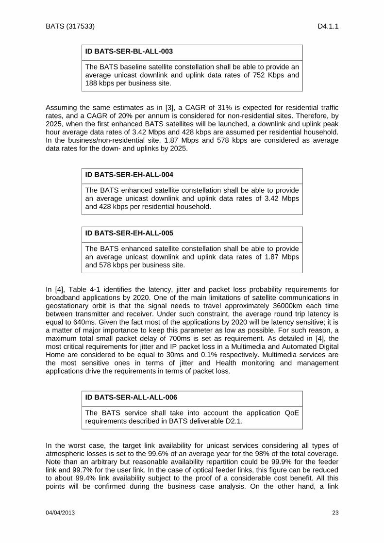
ID BATS-SER-BL-ALL-003
The BATS baseline satellite constellation shall be able to provide an average unicast downlink and uplink data rates of 752 Kbps and 188 kbps per business site.
Assuming the same estimates as in [3], a CAGR of 31% is expected for residential traffic rates, and a CAGR of 20% per annum is considered for non-residential sites. Therefore, by 2025, when the first enhanced BATS satellites will be launched, a downlink and uplink peak hour average data rates of 3.42 Mbps and 428 kbps are assumed per residential household. In the business/non-residential site, 1.87 Mbps and 578 kbps are considered as average data rates for the down- and uplinks by 2025.
ID BATS-SER-EH-ALL-004
The BATS enhanced satellite constellation shall be able to provide an average unicast downlink and uplink data rates of 3.42 Mbps and 428 kbps per residential household.
ID BATS-SER-EH-ALL-005
The BATS enhanced satellite constellation shall be able to provide an average unicast downlink and uplink data rates of 1.87 Mbps and 578 kbps per business site.
In [4], Table 4-1 identifies the latency, jitter and packet loss probability requirements for broadband applications by 2020. One of the main limitations of satellite communications in geostationary orbit is that the signal needs to travel approximately 36000km each time between transmitter and receiver. Under such constraint, the average round trip latency is equal to 640ms. Given the fact most of the applications by 2020 will be latency sensitive; it is a matter of major importance to keep this parameter as low as possible. For such reason, a maximum total small packet delay of 700ms is set as requirement. As detailed in [4], the most critical requirements for jitter and IP packet loss in a Multimedia and Automated Digital Home are considered to be equal to 30ms and 0.1% respectively. Multimedia services are the most sensitive ones in terms of jitter and Health monitoring and management applications drive the requirements in terms of packet loss.
ID BATS-SER-ALL-ALL-006
The BATS service shall take into account the application QoE requirements described in BATS deliverable D2.1.
In the worst case, the target link availability for unicast services considering all types of atmospheric losses is set to the 99.6% of an average year for the 98% of the total coverage. Note than an arbitrary but reasonable availability repartition could be 99.9% for the feeder link and 99.7% for the user link. In the case of optical feeder links, this figure can be reduced to about 99.4% link availability subject to the proof of a considerable cost benefit. All this points will be confirmed during the business case analysis. On the other hand, a link

BATS (317533) D4.1.1
04/04/2013 24
availability of 99.0% is required for multicast services as set in [4] when looking to the VoD streaming requirements in a Multimedia and Automated Digital Home scenario by 2020.
ID BATS-SER-ALL-ALL-007
The link availability of the BATS constellation shall not be less than 99.0% for multicast and 99.6% unicast services (for the 98% of the total coverage).
ID BATS-SER-ALL-ALL-008
In the case of optical feeder links, the unicast availability in BATS-SER-ALL-ALL-007 can be reduced to 99.4% link availability subject to the proof of a considerable cost benefit
The estimated number of households and business sites that will need to be served by the BATS satellite network in 2020 has been computed in [3]. It has been identified that the BATS constellation shall be able to serve at least 7.56 million households and 0.51 million businesses in the EU27 and Turkey. These figures have been computed based on studies from Ofcom [5] and Point Topic [6] looking at the addressable market and expected coverage for the different broadband access technologies by 2020. Different proportions of traffic to be carried by the satellite network and service take-up rates were considered based on the location of the user (i.e., remote/very rural/rural/suburban/urban) and its available terrestrial broadband infrastructure. It is important to note that these figures include not only the remote areas where satellite is going to be the only broadband access network available, but also those “underserved” areas where the integration of satellite and terrestrial access is the only way to ensure that the Digital Agenda data rate requirements and service availability are met.
ID BATS-SER-ALL-ALL-009
The BATS constellation shall be able to serve at least 7.56 million households and 0.51 million businesses in the EU27 plus Turkey.
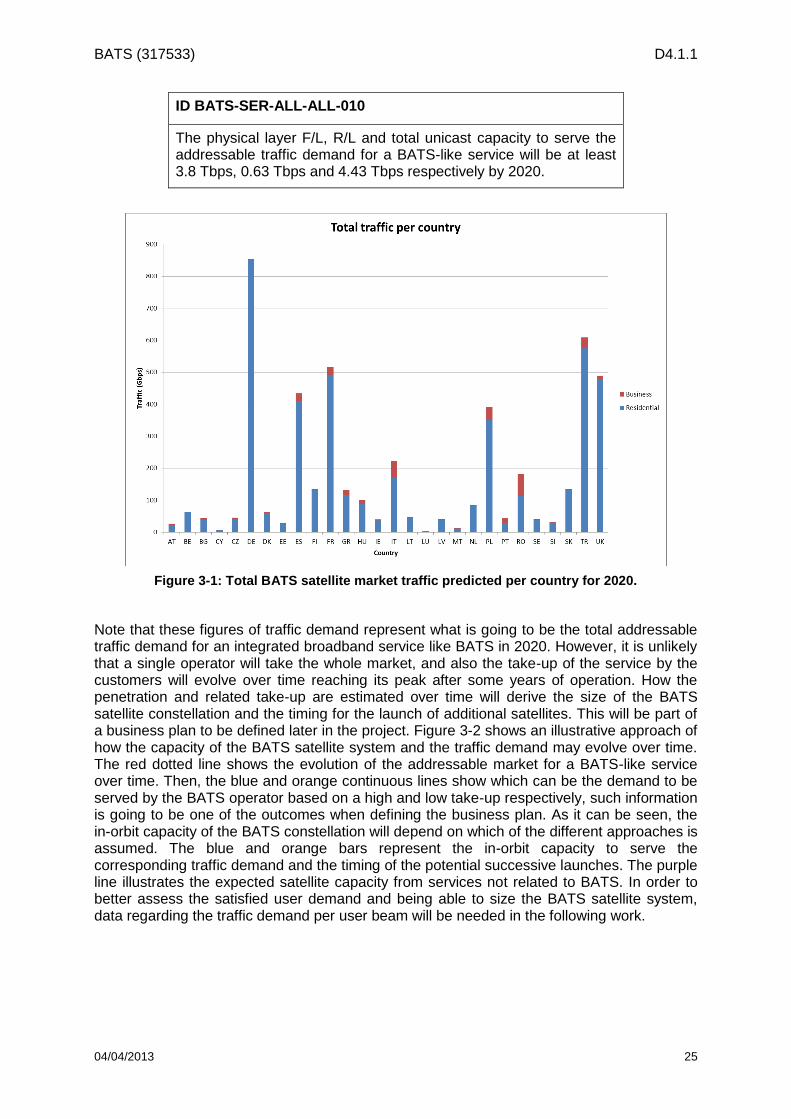
By 2020, the total addressable satellite traffic for a BATS-like service required for residential premises, considering the benefits of multicast, in the EU27 plus Turkey is equal to 4.5 Tbps. On the other hand, a total of 0.33Tbps business traffic over satellite is predicted to be required by 2020. This means that a total figure of 4.8Tbps of traffic will need to be distributed across the study countries. Assuming that an additional 1 Tbps of suitable satellite capacity is expected to be already in orbit by 2020, the total addressable physical layer unicast capacity for the BATS constellation will be at least 3.8 Tbps in the forward link, 0.63 Tbps in the return link and 4.43 Tbps in total. Figure 3-1 illustrates how the total 4.8 Tbps of BATS satellite traffic are distributed across the different study countries. Assuming the same growth trends are kept up to 2025, the addressable traffic in the forward link for residential and business premises will increase up to 17.3Tbps and 0.8Tbps respectively.
BATS (317533) D4.1.1
04/04/2013 25
ID BATS-SER-ALL-ALL-010
The physical layer F/L, R/L and total unicast capacity to serve the addressable traffic demand for a BATS-like service will be at least 3.8 Tbps, 0.63 Tbps and 4.43 Tbps respectively by 2020.
Note that these figures of traffic demand represent what is going to be the total addressable traffic demand for an integrated broadband service like BATS in 2020. However, it is unlikely that a single operator will take the whole market, and also the take-up of the service by the customers will evolve over time reaching its peak after some years of operation. How the penetration and related take-up are estimated over time will derive the size of the BATS satellite constellation and the timing for the launch of additional satellites. This will be part of a business plan to be defined later in the project. Figure 3-2 shows an illustrative approach of how the capacity of the BATS satellite system and the traffic demand may evolve over time. The red dotted line shows the evolution of the addressable market for a BATS-like service over time. Then, the blue and orange continuous lines show which can be the demand to be served by the BATS operator based on a high and low take-up respectively, such information is going to be one of the outcomes when defining the business plan. As it can be seen, the in-orbit capacity of the BATS constellation will depend on which of the different approaches is assumed. The blue and orange bars represent the in-orbit capacity to serve the corresponding traffic demand and the timing of the potential successive launches. The purple line illustrates the expected satellite capacity from services not related to BATS. In order to better assess the satisfied user demand and being able to size the BATS satellite system, data regarding the traffic demand per user beam will be needed in the following work.
Figure 3-1: Total BATS satellite market traffic predicted per country for 2020.

BATS (317533) D4.1.1
04/04/2013 26
Figure 3-2: Illustrating capacity versus demand over time.
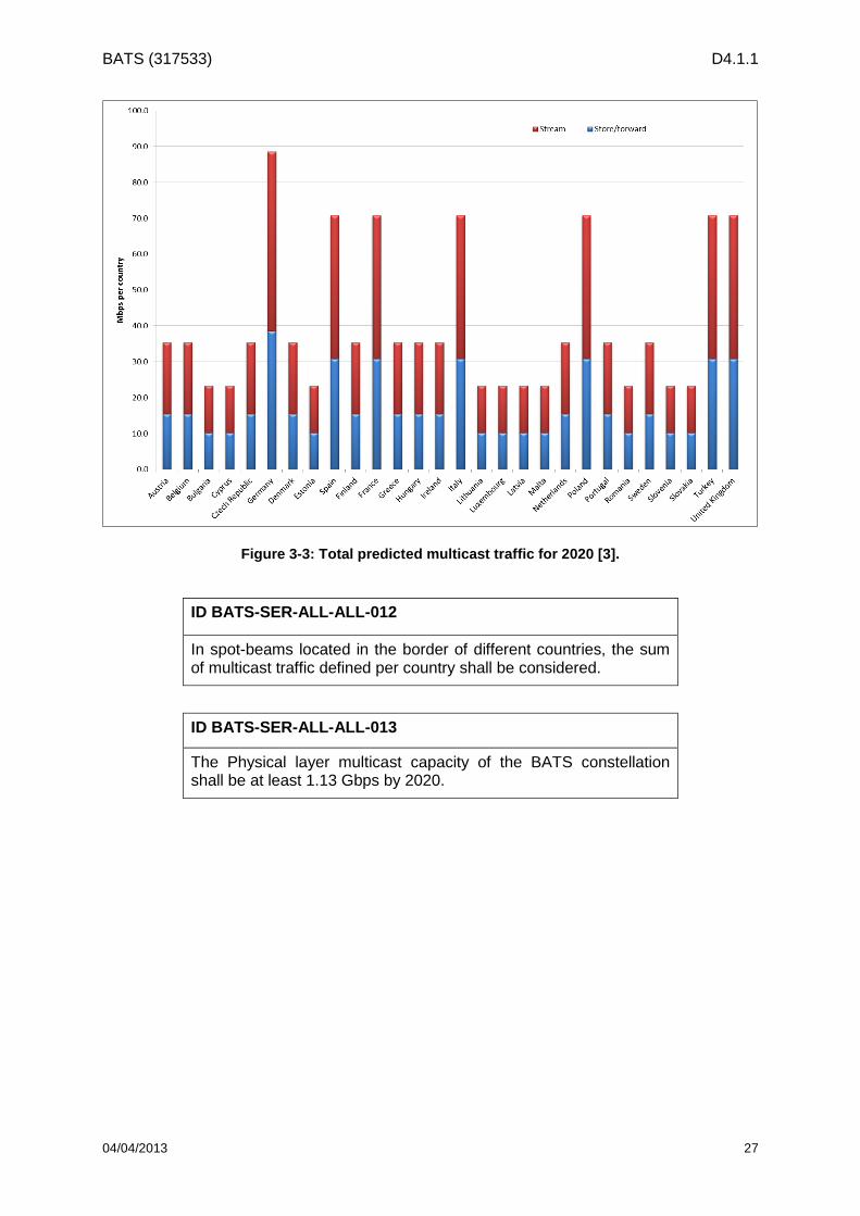
In [3], an initial estimation for the multicast traffic per country is computed based on recent BBC iPlayer statistics for the United Kingdom and considering that the top 20 shows –accounting for 15 hours- are multicasted in standard and high definition. The study countries are compared to the UK (reference) based on their size and GNI. Based on those assumptions, the total multicast traffic is predicted to be in the region of 1.13 Gbps of which 0.5 Gbps would be for cached content and 0.6 Gbps for live streams. Figure 3-3 shows the estimated multicast traffic demand per country. The BATS constellation multicast capacity shall be flexible to allow for different countries to have a different number of channels that can be considered for multicasting of streamed and cached TV content. It is expected that the same multicast traffic will be transmitted across each country and that each country will have different content from each other. As some spot-beams will be located in the border of different countries, the sum of multicast traffic defined per country should be considered.
ID BATS-SER-ALL-ALL-011
The BATS constellation multicast capacity shall be flexible to allow for different countries to have a different number of channels that can be considered for multicasting of streamed and cached TV content.
BATS (317533) D4.1.1
04/04/2013 27
Figure 3-3: Total predicted multicast traffic for 2020 [3].
ID BATS-SER-ALL-ALL-012
In spot-beams located in the border of different countries, the sum of multicast traffic defined per country shall be considered.
ID BATS-SER-ALL-ALL-013
The Physical layer multicast capacity of the BATS constellation shall be at least 1.13 Gbps by 2020.

BATS (317533) D4.1.1
04/04/2013 28
4 System Requirements
The total coverage envisaged by the BATS satellite system for the user link is the EU27 plus Turkey, which is equivalent to a region of 5.1 million km2. This area shall be served through different spot-beams. The feeder link will be formed by several spot-beams spread across the European continent in the centre of which the GWs shall be located. If possible, GW shall be located in existing Earth Station sites. The first phase of the baseline satellite mission configuration is based on a cluster of two collocated satellites covering half of the coverage each. In [3], the envisaged addressable traffic density per country is shown. There we can see that countries like Belgium, Germany, Denmark, Luxemburg, Netherlands, Poland, Slovenia, Slovakia, United Kingdom and Hungary are likely to include most of the hot-spots. Such countries represent the 35% of the study countries and cover the 23% of the total land coverage area. Hence, the first phase of the enhanced satellite mission configuration consists of a satellite providing additional capacity to the hot-spots, which translates to a geographical coverage of about the 30% of the overall EU27 plus Turkey. This requirement may be reformulated once traffic estimation data at a beam level is available.
ID BATS-SYS-ALL-ALL-014
The total coverage of the BATS satellite system shall consists of the EU27 countries and Turkey, which is equivalent to a region of 5.1 million km2.
ID BATS-SYS-ALL-ALL-015
The service area of the BATS system shall be split into regions and each region shall have a dedicated spot beam.
ID BATS-SYS-ALL-ALL-016
An appropriate number of spot beams shall provide the GW coverage. Each beam shall contain the optimal number of GWs located near towards the beam centre.
ID BATS-SYS-ALL-ALL-017
The GWs shall be located in existing Earth Station sites across the EU27 and Turkey as far as possible.
ID BATS-SYS-BL-ALL-018
The first two satellites of the baseline configuration by 2020 shall serve half the coverage each.
ID BATS-SYS-EH-ALL-019
The first satellite of the enhanced satellite mission in 2025 shall cover the 30% of the whole EU27 plus Turkey land area.

BATS (317533) D4.1.1
04/04/2013 29
For the satellite design based on the Q/V-band feeder link option, both the baseline and enhanced types of satellite will consist in two transparent payloads: forward and return links. On the other hand, looking at the enhanced spacecraft by 2025, the satellite design based on the optical feeder link configuration may consider a “partially regenerative” payload model. The baseline configuration with the optical feeder link option will consist in two transparent payloads. As aforementioned, the two different links will be served with a spot-beam type of coverage: a user cellular coverage (user beam (UB)) and a gateway multibeam coverage (GW). The forward link connects gateway stations to user terminals, whereas the return link connects the user terminals to the gateway stations.
ID BATS-SYS-ALL-ALL-020
The BATS satellites shall have one transparent forward payload and one transparent return payload. The BATS enhanced satellite based on an Optical feeder link may consider a “partially regenerative” payload model (subject to further analysis and trade-off).
ID BATS-SYS-ALL-ALL-021
The BATS satellites shall have a cellular multibeam coverage in the user link and a multibeam coverage in the feeder link.
As identified in the Terasat study [7], approximately 19 GEO satellites will operate in the Ka-band by 2014. In the MSBN study [8] it is stated that by 2020 the number of Ka-band S/Cs will amount to approximately 72 in the GEO orbit. Note that the standardized GEO satellite separation by the US FCC (Federal Communication Commission) is 2⁰. However, from the
regulatory point of view, it is possible that several S/Cs share the same orbital slot at different orbital inclination. For such configuration, it is necessary that the collocated satellites serve different geographical regions, so as to avoid mutual interference. Based on the analysis of the two aforementioned studies, by 2020 there will still be orbital slots above Europe available for Q/V-band. For the cluster of two satellites corresponding to the first deployment phase of the baseline mission the orbital slot at 13⁰E is to be initially considered, as it is
located above central Europe. The subsequent satellites of the BATS constellation (baseline and enhanced) are to be positioned between 30⁰W and 35⁰E.
ID BATS-SYS-ALL-ALL-022
The BATS satellite constellation shall consist of several baseline and enhanced S/Cs positioned in GEO orbit.
ID BATS-SYS-BL-ALL-023
The cluster of two collocated satellites corresponding to the first deployment phase of the baseline mission shall be positioned at the orbital slot in 13⁰E.

BATS (317533) D4.1.1
04/04/2013 30
ID BATS-SYS-ALL-ALL-024
The subsequent BATS satellites (baseline and enhanced) shall be positioned between 30⁰W and 35⁰E.
In order to allow a progressive deployment of the ground segment infrastructure a level of scalability would be desirable. This would allow starting to serve the whole coverage with fewer gateways than in the full capacity configuration. Given the fact the inherent increase in complexity on the on-board communication payload, this requirement is considered as optional.
ID BATS-SYS-ALL-ALL-025 (OPTIONAL)
The possibility of a progressive deployment of the feeder link ground segment infrastructure, ensuring that the basic service at each user beam is always guaranteed, is a desirable feature and should be included.
In order to adapt the system throughput to the evolutions of the traffic demand, the BATS enhanced constellation is designed to bring additional capacity to hot-spots. Also, it should have the flexibility to adapt its coverage and power/bandwidth distribution across spot-beams
ID BATS-SYS-EH-ALL-026
The BATS enhanced constellation shall have the flexibility to adapt its coverage and power/bandwidth distribution across spot-beams to follow the market trends.
The air interface of all configurations shall be based on DVB standards:
DVB-Sx standard on the FWD link, Sx meaning the next generation of DVB-S2 standard available by 2020,
DVB-RCS2 standard on the RTN link (see [11]) as the baseline scenario. In the frame of WP4.4, evolution of the RCS2 standard would be considered: depending on the outcome of the analysis, it could be considered as an alternate solution to the RCS2 standard.
ID BATS-SYS-ALL-ALL-027
The air interface of BATS satellite system should be based on existing DVB standards and planned evolutions.
ID BATS-SYS-ALL-ALL-028
The air interface of BATS satellite system on the FWD and RTN links should be based on 5% roll-off factor
BATS (317533) D4.1.1
04/04/2013 31
ID BATS-SYS-ALL-ALL-029
The FWD link air interface of BATS satellite system should support carrier symbol rate of up to 400 Msps
ID BATS-SYS-ALL-ALL-030
The RTN link air interface of BATS satellite system should support carrier symbol rate of up to 20 Msps
For justification of the considered performances, please refer to Annex B -.
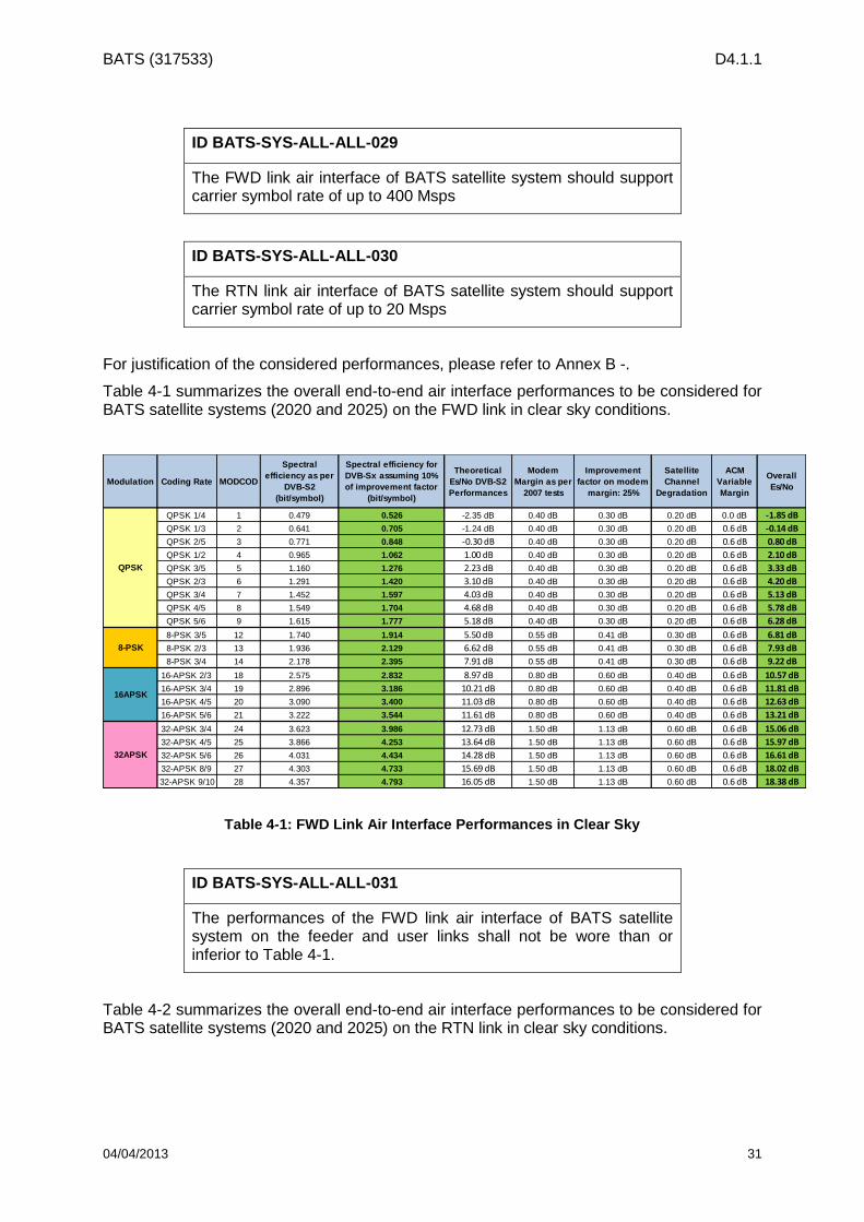
Table 4-1 summarizes the overall end-to-end air interface performances to be considered for BATS satellite systems (2020 and 2025) on the FWD link in clear sky conditions.
Modulation Coding Rate MODCOD
Spectral
efficiency as per
DVB-S2
(bit/symbol)
Spectral efficiency for
DVB-Sx assuming 10%
of improvement factor
(bit/symbol)
Theoretical
Es/No DVB-S2
Performances
Modem
Margin as per
2007 tests
Improvement
factor on modem
margin: 25%
Satellite
Channel
Degradation
ACM
Variable
Margin
Overall
Es/No
QPSK 1/4 1 0.479 0.526 -2.35 dB 0.40 dB 0.30 dB 0.20 dB 0.0 dB -1.85 dB
QPSK 1/3 2 0.641 0.705 -1.24 dB 0.40 dB 0.30 dB 0.20 dB 0.6 dB -0.14 dB
QPSK 2/5 3 0.771 0.848 -0.30 dB 0.40 dB 0.30 dB 0.20 dB 0.6 dB 0.80 dB
QPSK 1/2 4 0.965 1.062 1.00 dB 0.40 dB 0.30 dB 0.20 dB 0.6 dB 2.10 dB
QPSK 3/5 5 1.160 1.276 2.23 dB 0.40 dB 0.30 dB 0.20 dB 0.6 dB 3.33 dB
QPSK 2/3 6 1.291 1.420 3.10 dB 0.40 dB 0.30 dB 0.20 dB 0.6 dB 4.20 dB
QPSK 3/4 7 1.452 1.597 4.03 dB 0.40 dB 0.30 dB 0.20 dB 0.6 dB 5.13 dB
QPSK 4/5 8 1.549 1.704 4.68 dB 0.40 dB 0.30 dB 0.20 dB 0.6 dB 5.78 dB
QPSK 5/6 9 1.615 1.777 5.18 dB 0.40 dB 0.30 dB 0.20 dB 0.6 dB 6.28 dB
8-PSK 3/5 12 1.740 1.914 5.50 dB 0.55 dB 0.41 dB 0.30 dB 0.6 dB 6.81 dB
8-PSK 2/3 13 1.936 2.129 6.62 dB 0.55 dB 0.41 dB 0.30 dB 0.6 dB 7.93 dB
8-PSK 3/4 14 2.178 2.395 7.91 dB 0.55 dB 0.41 dB 0.30 dB 0.6 dB 9.22 dB
16-APSK 2/3 18 2.575 2.832 8.97 dB 0.80 dB 0.60 dB 0.40 dB 0.6 dB 10.57 dB
16-APSK 3/4 19 2.896 3.186 10.21 dB 0.80 dB 0.60 dB 0.40 dB 0.6 dB 11.81 dB
16-APSK 4/5 20 3.090 3.400 11.03 dB 0.80 dB 0.60 dB 0.40 dB 0.6 dB 12.63 dB
16-APSK 5/6 21 3.222 3.544 11.61 dB 0.80 dB 0.60 dB 0.40 dB 0.6 dB 13.21 dB
32-APSK 3/4 24 3.623 3.986 12.73 dB 1.50 dB 1.13 dB 0.60 dB 0.6 dB 15.06 dB
32-APSK 4/5 25 3.866 4.253 13.64 dB 1.50 dB 1.13 dB 0.60 dB 0.6 dB 15.97 dB
32-APSK 5/6 26 4.031 4.434 14.28 dB 1.50 dB 1.13 dB 0.60 dB 0.6 dB 16.61 dB
32-APSK 8/9 27 4.303 4.733 15.69 dB 1.50 dB 1.13 dB 0.60 dB 0.6 dB 18.02 dB
32-APSK 9/10 28 4.357 4.793 16.05 dB 1.50 dB 1.13 dB 0.60 dB 0.6 dB 18.38 dB
QPSK
8-PSK
16APSK
32APSK
Table 4-1: FWD Link Air Interface Performances in Clear Sky
ID BATS-SYS-ALL-ALL-031
The performances of the FWD link air interface of BATS satellite system on the feeder and user links shall not be wore than or inferior to Table 4-1.
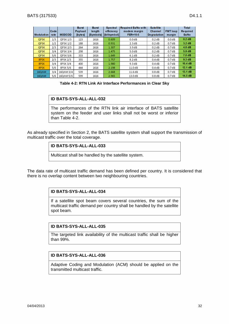
Table 4-2 summarizes the overall end-to-end air interface performances to be considered for BATS satellite systems (2020 and 2025) on the RTN link in clear sky conditions.
BATS (317533) D4.1.1
04/04/2013 32
Table 4-2: RTN Link Air Interface Performances in Clear Sky
ID BATS-SYS-ALL-ALL-032
The performances of the RTN link air interface of BATS satellite system on the feeder and user links shall not be worst or inferior than Table 4-2.
As already specified in Section 2, the BATS satellite system shall support the transmission of multicast traffic over the total coverage.
ID BATS-SYS-ALL-ALL-033
Multicast shall be handled by the satellite system.
The data rate of multicast traffic demand has been defined per country. It is considered that there is no overlap content between two neighbouring countries.
ID BATS-SYS-ALL-ALL-034
If a satellite spot beam covers several countries, the sum of the multicast traffic demand per country shall be handled by the satellite spot beam.
ID BATS-SYS-ALL-ALL-035
The targeted link availability of the multicast traffic shall be higher than 99%.
ID BATS-SYS-ALL-ALL-036
Adaptive Coding and Modulation (ACM) should be applied on the transmitted multicast traffic.

BATS (317533) D4.1.1
04/04/2013 33
ID BATS-SYS-ALL-ALL-037
The ACM MODCOD selection shall take into account the link budget performances of all connected/active users within a satellite spot beam.
It is assumed that all connected/active users will feedback link budget performances to the gateway. This means that the ACM performances for the multicast traffic would be lower than for the unicast as the MODCOD selection shall be compatible of the worst link budgets over all connected/active users. If deemed necessary, a limit on the worst supported link budget (in line with the targeted link availability) may be implemented in order to keep a good spectral efficiency over the multicast traffic data to be transmitted. It would mean that some users in very deep fading conditions would not be able to receive the multicast traffic.
ID BATS-SYS-ALL-ALL-038
The multicast traffic should be transmitted in the exclusive FSS band.
ID BATS-SYS-ALL-ALL-039
The multicast traffic shall be transmitted through the user satellite multi-spot beam (no implementation of linguistic beams)
ID BATS-SYS-ALL-ALL-040
The multicast traffic should be transmitted on one carrier per spot beam, time multiplexed with unicast traffic
ID BATS-SYS-ALL-ALL-041
The user terminal side should implement two receivers/demodulators: one for the multicast traffic (which is only available in one carrier) and another one for unicast traffic (when the unicast traffic is not on the same carrier as the multicast traffic)
For justification of the selected solution, please refer to Annex C -.
The related frequency plan is illustrated in Figure 4-1 for a 4-colour frequency reuse scheme. It should be noted that only one polarization is considered (thus, two colors).
Some advantages of this solution are:
If appropriate, it is possible to adjust the multicast traffic data rate to be transmitted as it uses common resources with the unicast traffic.
Depending on the MODCOD selection strategy, it is possible to adjust the link availability of the multicast traffic.
In both cases, this is a trade-off between capacity dedicated to multicast vs. capacity dedicated to unicast.

BATS (317533) D4.1.1
04/04/2013 34
Figure 4-1: Frequency plan for multicast traffic.

BATS (317533) D4.1.1
04/04/2013 35
5 Space Segment Requirements
This sections aims at defining a first level of space segment requirements. These requirements will be reviewed and refined during the frame of the study in light of the satellite system sizing and design.
For the 2020 timeframe satellite scenarios, the space segment requirement (for the user link and the feeder link in Q/V band) can benefit from the ESA Terabit Studies performed by TAS and Astrium.
However, for the 2025 timeframe satellite scenarios and for the optical feeder link, there is not such a reference scenario, making the definition of the space segment requirement more subject to review in the frame of the study.
Two timeframes are considered, with two different approaches:
2020 timeframe: the selected approach is to maximise the raw satellite system capacity, allocating the same bandwidth and power to all user beams,
2025 timeframe: the selected approach is to provide coverage flexibility in order to provide the service in hot demand areas.
5.1 Common requirement for both 2020 and 2025 S/C’s
5.1.1 Satellite
ID BATS-SAT-ALL-ALL-042
The design operational lifetime shall be at least 15 years.
ID BATS-SAT-ALL-ALL-043
The satellite shall be compatible with initial placement into geostationary transfer orbit (GTO) by at least two launcher vehicles.
ID BATS-SAT-ALL-ALL-044
The selected launchers shall offer a 5 meter diameter fairing.
ID BATS-SAT-ALL-ALL-045
In case of Electrical Orbit Raising strategy for transfer phase, the maximum duration of the EOR phase shall be less than 120 days; such requirement applies to Baseline and Enhanced configurations.
ID BATS-SAT-ALL-ALL-046
The Beam pointing error guaranteed to the mission will be less than 0.025°.

BATS (317533) D4.1.1
04/04/2013 36
5.1.2 Payload
5.1.2.1 User Link Payload
Frequency Band and Polarisation
ID BATS-SAT-ALL-ALL-047
On the FWD link, the downlink frequency band shall be based on the 17.3 – 20.2 GHz frequency band.
It should be noted that 17.3 – 17.7 and 19.7 – 20.2 GHz are frequency bands exclusively allocated to the Fixed Satellite Service – FSS – service, whereas the 17.7 – 19.7 GHz is a frequency band shared between Fixed Service – FS – (terrestrial service) and FSS services.
ID BATS-SAT-ALL-ALL-048
Part of the exclusive band shall be included in each user spot beam.
ID BATS-SAT-ALL-ALL-049
On the RTN link, the uplink frequency band shall be based on the bands 27.5 – 27.8285 GHz, 28.4445 – 28.9485 GHz and 29.4525 – 30 GHz.
ID BATS-SAT-ALL-ALL-050
On both user uplink and downlink, the circular polarisation shall be used.
ID BATS-SAT-ALL-ALL-051
On any given uplink and downlink user spot beam, orthogonal polarisation shall be used.
Payload RF Performances
Minimum FWD downlink EIRP density
The following assumptions have been considered in order to derive the minimum EIRP density that the payload shall deliver to ensure that the targeted link availability is met:
Terminal G/T performances of 18.4 dB/K at 20 GHz (19 dB/K minus 0.6 dB for pointing loss),
The total atmospheric attenuation, including the degradation of the terminal G/T due to rain, over the service area at the highest frequency (20.2 GHz) for 99.7% link availability,
Most robust MODCOD: QPSK ¼ with a required Es/No of -2 dB,

BATS (317533) D4.1.1
04/04/2013 37
Other contributors to the link budget (i.e. uplink contributions and downlink contributions) than the downlink thermal link budget are assumed to not degrade the overall link budget by no more than 0.5 dB.
The results of the analysis leading to the computation of the minimum EIRP density over the service area shown in the two following figures: the first one providing the CDF and the second one the related map.
Figure 5-1: CDF of Minimum EIRP Density over the Service Area
Figure 5-2: Map of Minimum EIRP Density over the Service Area

BATS (317533) D4.1.1
04/04/2013 38
It means that in order to support 99.7% of link availability on the user downlink, the minimum EIRP density ranges from 23 up to 33 dBW/MHz, the most demanding area being the North-East of the coverage (Finland), not the most populated area.
ID BATS-SAT-ALL-ALL-052
The minimum satellite EIRP density on the FWD link shall comply with Figure 5-2.
Note that the analysis has been done at 20.2 GHz which is the worst case frequency, for 99.7% link availability. Half of the beams would get a lower frequency, with a maximum frequency at 18.75 GHz.
Minimum RTN uplink G/T
ID BATS-SAT-ALL-ALL-053
The minimum payload G/T achievable on the RTN uplink service area shall be higher than 20 dB/K over 95% of the coverage.
Methodology for sizing the payload RF performances
The main objective of the 2020 BATS satellite system is to maximise the overall satellite system capacity on both the FWD and the RTN links, putting priority on the FWD link, while achieving the targeted link availability over at least 98% of the service area.
Therefore, the payload RF performances (EIRP, G/T, antenna C/I, linearity) shall be optimised together with ground segment performances (RF/optical on the feeder link, RF on the terminal and air interface) in order to maximise the capacity, while achieving the targeted link availability.
Transponder Mode of Operation
ID BATS-SAT-ALL-ALL-054
On the FWD link, the transponder should be operated in ALC (Automatic Level Control) mode.
ID BATS-SAT-ALL-ALL-055
On the RTN link, the transponder should be operated in FGM (Fixed Gain Mode).
Equipment Redundancy
ID BATS-SAT-ALL-ALL-056
A general rule for the active equipment (LNAs, tubes) shall be to include at least 15% redundancy.

BATS (317533) D4.1.1
04/04/2013 39
5.1.2.2 Feeder Link Payload
Gateway Site Deployment
ID BATS-SAT-ALL-ALL-057
A general rule for the active equipment (LNAs, tubes) shall be to include at least 15% redundancy.
A progressive deployment of GWs is envisaged. It implies that a minimum service in all user spot beams with a reduced number of GWs should be provided (nice to have feature, see BATS-SYS-ALL-ALL-026).
Gateway Site Diversity
The selected baseline GW site diversity is based on the “N+P” solution, i.e. for N active GWs, P additional GWs are deployed as back-up GWs.
The satellite feeder link payload shall support the N+P site diversity solution.
ID BATS-SAT-ALL-ALL-058
The satellite feeder link payload should support the N+P site diversity solution.
It should be noted that alternate site diversity solutions will be investigated in the frame of the study (e.g. the “smart site diversity” based on the SS-TDMA solution) and would be considered as an option if deemed appropriate.
Feeder Link Sizing
As a general statement, the feeder link should not be the sizing link in the overall end-to-end system performances. This could be translated in the following requirements:
In terms of overall link budget performances in clear sky conditions, the feeder link shall not degrade the median user link budget by more than 1.5 dB,
In terms of link availability, the feeder link shall support a link availability higher than 99.9%, in line with 99.7% user link availability to achieve 99.6% overall link availability) with a link budget that could be degraded with respect to the link budget in clear sky conditions. This degradation shall not decrease the related user beam capacity by more than 25 %.
The requirements are provided for guidance but they will be refined in the frame of the study in light of feeder link sizing analysis.
ID BATS-SAT-ALL-ALL-059
In terms of overall link budget performances in clear sky conditions, the feeder link shall not degrade the median user link budget by more than 1.5 dB.
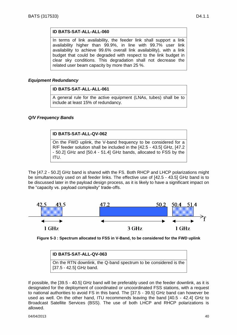
BATS (317533) D4.1.1
04/04/2013 40
ID BATS-SAT-ALL-ALL-060
In terms of link availability, the feeder link shall support a link availability higher than 99.9%, in line with 99.7% user link availability to achieve 99.6% overall link availability), with a link budget that could be degraded with respect to the link budget in clear sky conditions. This degradation shall not decrease the related user beam capacity by more than 25 %.
Equipment Redundancy
ID BATS-SAT-ALL-ALL-061
A general rule for the active equipment (LNAs, tubes) shall be to include at least 15% of redundancy.
Q/V Frequency Bands
ID BATS-SAT-ALL-QV-062
On the FWD uplink, the V-band frequency to be considered for a R/F feeder solution shall be included in the [42.5 - 43.5] GHz, [47.2 - 50.2] GHz and [50.4 - 51.4] GHz bands, allocated to FSS by the ITU.
The [47.2 - 50.2] GHz band is shared with the FS. Both RHCP and LHCP polarizations might be simultaneously used on all feeder links. The effective use of [42.5 - 43.5] GHz band is to be discussed later in the payload design process, as it is likely to have a significant impact on the “capacity vs. payload complexity“ trade-offs.
Figure 5-3 : Spectrum allocated to FSS in V-Band, to be considered for the FWD uplink
ID BATS-SAT-ALL-QV-063
On the RTN downlink, the Q-band spectrum to be considered is the [37.5 - 42.5] GHz band.
If possible, the [39.5 - 40.5] GHz band will be preferably used on the feeder downlink, as it is designated for the deployment of coordinated or uncoordinated FSS stations, with a request to national authorities to avoid FS in this band. The [37.5 - 39.5] GHz band can however be used as well. On the other hand, ITU recommends leaving the band [40.5 - 42.4] GHz to Broadcast Satellite Services (BSS). The use of both LHCP and RHCP polarizations is allowed.

BATS (317533) D4.1.1
04/04/2013 41
37.5 40.5
3 GHzf
39.542.5
2 GHz
37.5 40.5
3 GHzf
39.542.5
2 GHz
Figure 5-4 : Spectrum allocated to FSS in Q-Band, to be considered for the RTN downlink
Payload Requirements for Q/V feeder section:
For the FWD link, the feeder section shall be able to receive, transparently process and distribute signals issued from a number of gateways spread over the satellite multispot coverage. The total bandwidth to process is N x 1.45 GHz, where N is the number of user beams (a preliminary estimation of 120 to 150 is provided in Section 5.2.3.2).
ID BATS-SAT-ALL-QV-064
The space segment associated to Q/V band feeder link options will involve transparent signal processing on the forward and on the return links, in both 2020 and 2025 timeframes.
ID BATS-SAT-ALL-QV-065
The feeder-to-user beam connectivity should ensure the implementation of N+P gateway diversity.
ID BATS-SAT-ALL-QV-066
The satellite gateway Q/V receive antennas shall be able to operate in both LHCP and RHCP polarizations.
The feeder link payload section dedicated to the RTN link is in charge of RTN link signal channelization, amplification, and R/F transmission to the system gateways.
ID BATS-SAT-ALL-QV-067
For the RTN link, the feeder section shall ensure the channelization and the amplification of the signals issued from the user link receive section.
ID BATS-SAT-ALL-QV-068
The RTN link user-to-gateway beam connectivity shall be congruent with the FWD link connectivity.

BATS (317533) D4.1.1
04/04/2013 42
5.2 Space Segment Requirements for 2020 timeframe
ID BATS-SAT-BL-ALL-069
The selected approach for the 2020 satellites is to maximise the raw satellite system capacity, allocating the same bandwidth and power to all user beams.
In addition, in order to further increase the capacity supported at a given orbital slot, two co-located satellites, each serving half of the coverage area, will be launched.
In the following sub-sections, satellite, platform and payload requirements are defined.
5.2.1 Satellite
ID BATS-SAT-BL-ALL-070
Two satellites operated over the same orbital slot shall be designed, assuming a target launch by 2020.
ID BATS-SAT-BL-ALL-071
The targeted orbital slot is 13°East, geosynchronous orbital location.
ID BATS-SAT-BL-ALL-072
The satellite design of the Baseline configuration shall be compatible of the platform capability as detailed in Section 9.1.
5.2.2 Platform
ID BATS-SAT-BL-ALL-073
The targeted platform shall be the Alphabus Extended platform. Further description is provided in Section 9.1.
5.2.3 Payload
5.2.3.1 Introduction The satellite payload shall consist of:
A FWD link payload, made of:
o A receive feeder uplink section. Two configurations shall be investigated:
Feeder uplink in V-band,
Optical feeder link.

BATS (317533) D4.1.1
04/04/2013 43
o A transmit user downlink section in Ka-band.
A RTN link payload, made of:
o A receive user uplink section in Ka-band.
o A transmit feeder downlink section. Two configurations shall be investigated:
Feeder downlink in Q-band,
Optical feeder link.
In the following sub-sections, user and feeder link payloads are described rather than FWD and RTN link payloads as:
requirements are shared between the user uplink and the user downlink,
two technologies shall be investigated on the feeder link: Q/V band and optical. User link requirements are common to both technologies whereas feeder link requirements are specific.
5.2.3.2 User Link Payload
Coverage Area
ID BATS-SAT-BL-ALL-074
The satellite payload shall provide a continuous multi-spot beam coverage area on the user link (FWD and RTN) over the EU27 countries plus Turkey.
ID BATS-SAT-BL-ALL-075
FWD and RTN user link satellite spot beams shall be congruent.
Frequency Reuse Scheme and Frequency Plan
ID BATS-SAT-BL-ALL-076
A regular 4-colour frequency reuse scheme should be implemented on both the FWD link and the RTN link.
ID BATS-SAT-BL-ALL-077
On the FWD downlink, the frequency plan should comply with Figure 5-5, allocating one colour per user spot beam

BATS (317533) D4.1.1
04/04/2013 44
Figure 5-5: FWD Downlink Frequency Plan.
On the FWD downlink, 1.45 GHz of spectrum is allocated per user spot beam.
The ratio between RTN and FWD capacity (or data) is expected to be equal to 1:6 by 2020 as described in Section 3.
Assuming that:
the spectral efficiency on the RTN link may be lower than or close to the one achieved on the FWD link,
the burst scheduling algorithm on the RTN link may be less efficient than the traffic scheduling algorithm on the FWD link,
the RTN link needs to be oversized in terms of capacity in order to ensure that the bottleneck remains the FWD capacity (the FWD link being the most expensive resource for the satellite),
it is proposed to use only two chunks of bandwidth on the RTN link, i.e. the slots 28.4445 – 28.9485 GHz and 29.4525 – 30 GHz. It would lead to a ratio in terms of RTN to FWD bandwidth equal to 1:2.76. It means that either:
the spectral efficiency of the RTN link can be more than twice less efficient than that of the forward link.
Or at same spectral efficiency (FWD and RTN), the RTN has more than twice more capacitive than the FWD, ensuring that the RTN link is not the bottleneck of the system,
Or any mix of the two above scenarios.
ID BATS-SAT-BL-ALL-078
On the RTN downlink, the frequency plan should comply with Figure 5-6, allocating one colour per user spot beam

BATS (317533) D4.1.1
04/04/2013 45
Figure 5-6: RTN Uplink Frequency Plan
Range of user spot beam number
Taking into account platform constraints, the total number of user spot beams (thus, payload equipment) that can be implemented would probably range from 120 to 150 spot beams per spacecraft, i.e. 240 to 320 user spot beams over the entire service area.
The exact number of spot beams will be defined taking into account antenna design constraints while trying to maximise the capacity and achieving the targeted link availability.
Note that,
1. 240 to 320 beams with:
1.45 GHz of bandwidth per beam on the FWD link would lead to 348 to 464 GHz of total FWD link bandwidth,
526 MHz of bandwidth per beam (in average) on the RTN link would lead to 126 to 168 GHz of total RTN link bandwidth.
2. An analysis of user spot beam size and number is provided in Annex D -.
5.2.3.3 Feeder Link Payload
Coverage Area
ID BATS-SAT-BL-ALL-079
The satellite payload feeder link coverage shall be within the service area, i.e. the EU27 countries plus Turkey.
Number of Gateway Sites
ID BATS-SAT-BL-ALL-080
The required number of gateway sites to support the operation of both satellites shall be minimised. The reuse of gateway sites for the operation of both satellites shall be considered. To allow such operation, it is assumed that both satellites may be operated with a maximum orbital separation of 0.3°.

BATS (317533) D4.1.1
04/04/2013 46
Payload Requirements for Optical feeder section:
Optical link is able to transport very high data rate, up to several times 100Gbps thanks to optical wave length multiplexing but depending on the availability of space qualified optoelectronics. Several links will be necessary to support the overall throughput.
There are two ways to transmit the data to the users: transparent (there is no on board modulation or coding) or regenerative (modulation and/or coding are performed on board). Two basic cases shall be envisaged:
• Transparent: can be performed either in digital or analog mode.
o Digital transparent architecture: modulation and coding of the signal are performed by the Gateway then sampled and transmitted optically to the satellite. The satellite demodulates the optical signal and uses samples to create the RF signal.
o Analog transparent architecture: the RF signal modulates directly the optical signal which is demodulated on board. The IF shall be selected in order to minimize the impact on the RF payload.
• Regenerative: can be performed with two different options:
o Full regenerative: data are transmitted in baseband over the optical signal. Modulation and coding of the user links are performed on-board.
o Intermediate regenerative: data are transmitted in baseband over the optical signal but the coding of the user links is performed on ground (only modulation is performed on board).
ID BATS-SAT-BL-OPT-081
The payload model for the baseline configuration with optical feeders shall be transparent.
ID BATS-SAT-BL-OPT-082
For optical links, the redundancy is handled at two levels:
• For the opto-electronic part, the power amplifiers shall be redundant internally (additional pumping diodes shall be used to cover failures)
• For the electronic part, conventional redundancy scheme shall be applied.
5.3 Space Segment Requirements for 2025 timeframe
ID BATS-SAT-EH-ALL-083
The selected approach for the 2025 satellite(s) is to provide coverage flexibility in order to provide the service in hot demand areas. In this scenario, a satellite should only cover the 30% of the whole EU27 plus Turkey land area.

BATS (317533) D4.1.1
04/04/2013 47
ID BATS-SAT-EH-ALL-084
It is assumed that part of the coverage area of the satellite would be identified at the beginning of the program, then the remaining coverage area being flexibly defined in orbit (also called post launch flexibility).
ID BATS-SAT-EH-ALL-085
The satellite(s) will be operated at an orbital slot different from the 2020 satellites, allowing frequency and gateway site reuse.
ID BATS-SAT-EH-ALL-086
The first enhanced satellite operated shall be designed assuming a target launch by 2025.
The satellite, platform and payload requirements defined for the 2020 satellite scenarios are applicable except otherwise stated in the following sub-sections.
A preliminary review of post launch flexibility options is provided in Annex E -. This topic will be studied more in detail in the next study phases.
5.3.1 Satellite
ID BATS-SAT-EH-ALL-087
The targeted orbital slot ranges from 30° West to 35° East, geosynchronous orbital location. In the following of the project, it is proposed to perform the analysis at one orbital location, e.g. 30°East.
ID BATS-SAT-EH-ALL-088
The satellite design of the Enhanced configuration shall be compatible of the platform capability as detailed in Section 9.2.
5.3.2 Platform
The targeted platform is the evolution of the Alphabus Extended platform through the introduction of Neosat technologies. Further description is provided in Section 9.2.
ID BATS-SAT-EH-ALL-089
The targeted platform is the evolution of the Alphabus Extended platform through the introduction of Neosat technologies.

BATS (317533) D4.1.1
04/04/2013 48
5.3.3 Payload
5.3.3.1 User Link Payload
Coverage Area
ID BATS-SAT-EH-ALL-090
The satellite payload shall cover 30% of the service area on the user link (FWD and RTN) of the EU27 countries plus Turkey.
ID BATS-SAT-EH-ALL-091
Part of the 30% coverage area will be fixed and defined at the beginning of the program; the remaining part shall be flexibly defined in orbit in order to meet the traffic demand.
In the frame of the study, solutions should be investigated in order to answer to the above requirement, making the fixed coverage defined at the beginning of the program as small as possible while taking as constraint that the cost of flexibility has to be less than the 10% in terms of capacity reduction compared to a fixed configuration by launch.
ID BATS-SAT-EH-ALL-092
The cost of flexibility has to be less than the 10% in terms of capacity reduction compared to a fixed configuration by launch
Frequency Band and Polarisation
There are no specific requirements for the 2025 timeframe compared to the baseline configuration.
Frequency Reuse Scheme and Frequency Plan
The satellite resource will be flexibly allocated over the coverage area. It is most likely that frequency reuse scheme and frequency plan would be non-regular.
The different solutions will be investigated in the frame of the study, while trying to maximise the capacity in hot demand areas.
Range of user spot beam number
30% of the service area would have to be covered.
Evolution of the Alphabus extended platform is foreseen for this scenario.
It is most likely that the design driver for the number of spot beams and spot beam size will be the size of the antenna that could be considered for the 2025 timeframe.
This topic will be investigated in the frame of the study.

BATS (317533) D4.1.1
04/04/2013 49
Payload RF Performances
Methodology for sizing the payload RF performances
The main objective of the 2025 BATS satellite system is to provide additional capacity in hot demand areas, representing 30% of the service area, including in-orbit coverage flexibility.
Part of the 30% coverage area will be fixed and defined at the beginning of the program; the remaining part shall be flexibly defined in orbit in order to meet the traffic demand.
The payload RF performances (EIRP, G/T, antenna C/I, linearity) shall be optimised together with ground segment performances (RF/optical on the feeder link, RF on the terminal and air interface) in order to maximise the capacity in hot demand areas while trying to provide the highest degree of coverage flexibility.
The following constraint shall be considered: the cost of flexibility has to be less than the 10% in terms of capacity reduction compared to a fixed configuration by launch.
5.3.3.2 Feeder Link Payload
Coverage Area
ID BATS-SAT-EH-ALL-093
The satellite payload feeder link coverage shall be based as much as possible on the gateway sites used for the 2020 satellites in order to minimise the deployment of new gateway sites.
Number of Gateway Sites
ID BATS-SAT-EH-ALL-094
The gateway sites used for the 2020 satellites shall be reused as much as possible in order to minimise the deployment of new gateway sites.
Payload Requirements for Optical feeder section:
ID BATS-SAT-EH-OPT-095
The payload model for the enhanced configuration with optical feeders shall be either transparent or partly regenerative.

BATS (317533) D4.1.1
04/04/2013 50
6 Gateway Requirements
6.1 Q/V Gateway
ID BATS-GW-ALL-QV-096
Each Q/V feeder station shall handle at least 4 spots in emission and reception
ID BATS-GW-ALL-QV-097
The gateway frequency range for the transmission and reception sections shall be compliant with the feeder link frequency plan.
ID BATS-GW-ALL-QV-098
The Q/V gateway antenna shall support circular right and left polarization. The cross-polarization isolation shall be better than 27 dB
ID BATS-GW-ALL-QV-099
The transmit gain shall be greater than 65 dBi at 47.5 GHz
ID BATS-GW-ALL-QV-100
The gateway antenna diagram shall comply with the ITU masks.
The feeder uplink will involve at least 3 GHz useful bandwidth (on two polarizations). The amplification stage in the gateway will very likely rely on sub-band splitting with separate amplification of the sub-bands. The gateway amplification stage shall provide 500W for each sub-band of 1.45 GHz (corresponding to the useful band dedicated to the forward link in one beam), in other word, per access.
ID BATS-GW-ALL-QV-101
The gateway power amplification stage shall be able to provide a maximum output power of 500 W per access when the HPAs are operated at saturation.
ID BATS-GW-ALL-QV-102
The station shall implement uplink power control function.

BATS (317533) D4.1.1
04/04/2013 51
ID BATS-GW-ALL-QV-103
G/T including the pointing losses shall be greater than 37dBi/K at 37.5GHz and 20° elevation.
Preliminary considerations on the gateway antenna isolation
The previously stated requirements are typically achievable with a 5m reflector diameter. However additional constraints may appear later in the study phase, while considering the opportunity to re-use the gateway sites in the system architecture. Indeed, provided that the gateway antenna pattern guarantees sufficient angular isolation with respect to the satellite spacing, the possibility to co-locate several gateways at the same location is a convenient mean to reduce the ground segment cost and improve the satellite feeder antenna performance. In BATS 2020 timeframe scenario, the two satellites will share an orbital slot. The difference in longitude between their respective positions may not exceed 0.3°, though this value will be assessed throughout the study. This may constrain the gateway antenna design.
As a preliminary survey, and so as to illustrate the issue, Figure 6-1 and Figure 6-2 show typical antenna gains with respect to the angular separation with the beam centre, for a 5m reflector and for an 8m reflector respectively. The extreme frequency values in Q and V band have been considered, and the envelope generated by these two curves is considered here as the affordable isolation over the operating bandwidth.
It can be observed that with a 5m antenna, an isolation of 18 dB is obtained for an angular separation of 0.1° to 0.15, while 25 dB isolation is reached for an angular separation greater than 0.18° and 30 dB isolation is reached for an angular separation greater than 0.27°.
For the comparison, with an 8m antenna, an isolation of 18 dB is obtained for an angular separation of 0.06°, while 25 dB isolation is reached for an angular separation greater than 0.12°, and 30 dB isolation is reached for an angular separation greater than 0.17°.
Further analyses taking will be carried out during the study phase, taking into account the feeder link budgets.

BATS (317533) D4.1.1
04/04/2013 52
Figure 6-1 Antenna pattern for a 5m antenna in Q/V band
Antenna pattern for a 5m antenna
-80,0000
-70,0000
-60,0000
-50,0000
-40,0000
-30,0000
-20,0000
-10,0000
0,0000
0 0,05 0,1 0,15 0,2 0,25 0,3 0,35
Theta (°)
Dep
oin
tin
g lo
sses (
dB
)
Antenna gain at lowest Rx frequency: 37.5 GHz
Antenna gain at highest Tx frequency: 51.4 GHz
minimum spatial isolation on all feeder band
Figure 6-2: Figure 6 2: Antenna pattern for an 8m antenna in Q/V band.
6.2 Optical Gateway The set of requirements detailed in this section express the main design drivers associated to the Optical gateway (OGW) dimensioning.

BATS (317533) D4.1.1
04/04/2013 53
ID BATS-GW-ALL-OPT-104
The OGW shouldbe able to receive or transmit in the range of the optical C band and L band (around 1.55 µm) from one on satellite terminal.
ID BATS-GW-ALL-OPT-105
The maximum size of the telescopes should be lower than 500 mm.
ID BATS-GW-ALL-OPT-106
Each OGW should consider one of the following options:
• One single transmit/receive telescope
• Separate single transmit and receive telescope
• Separate multiple aperture transmit and receive telescope
ID BATS-GW-ALL-OPT-107
The total throughput is split between several operational OGW.
For site diversity, redundant terminal will be either local or regional:
• The operational OGW shall be located at a distance > TBC between them.
• The redundant local OGW shall be located within a distance < 300 km from the operational terminals.
• The redundant regional OGW shall be located within a distance > 500 km from the operational terminals.
ID BATS-GW-ALL-OPT-108
The OGW shall be able to communicate with the satellite terminal with an elevation angle down to 20 deg.
ID BATS-GW-ALL-OPT-109
Handover related to the optical link availability (cloud, atmosphere, etc.) between gateways shall be performed by switching the relevant traffic from the operational OGWs to the selected ones (under clear sky conditions) with minimization of the interruption of the service.

BATS (317533) D4.1.1
04/04/2013 54
ID BATS-GW-ALL-OPT-110
The following eye safety standard is applicable and shall be conformed to: the European Comity of Normalization (CEN) defined in its second version of the Norm EN 60825-1 the level of Maximal Permit Exposure (EMP) to lasers. This level is based on the values of the International Commission on Non-Ionizing Radiation protection (ICNIRP)

BATS (317533) D4.1.1
04/04/2013 55
7 User Terminal Requirements
This section refers to the satellite user terminal (UT, often referred to as a VSAT). All scenarios considered in the BATS project assume the Ka-band on the user link. A list of requirements is presented in this section to build the realistic constraints of the Ka-band user terminal which will impact the final satellite network architecture and dimensioning for the project. The key drivers for the UT are cost, performance and power consumption. The user terminals chosen as a state of the art baseline in [3] are the Newtec MDM2200 exclusive polarization terminal and the Viasat Surfbeam 2 dual polarization terminal.
7.1 Cost Requirements
7.1.1 Equipment
The volume deployment depends on the low-end user pricing to make satellite broadband technology economically affordable and enable service take-up. Note that today’s Ka-band UTs can cost less than a high-end smartphone. In 2020, the cost for the UT consisting of antenna, outdoor electronics and indoor device shall cost no more than today’s. As identified in [3], the state of the art baseline Ka user terminal cost figure is about 300 euros.
ID BATS-UT-ALL-ALL-111
The UT shall cost no more than today’s UT (i.e., 300 euros).
The later enhanced service implies a deployment of the order of 1M UTs or more, hence the costs should show the economies of scale.
ID BATS-UT-EH-ALL-112
By the time the project reaches very large numbers of users the UT shall cost 75% of today’s UT.
The UT needs to be manufactured to an acceptable quality to avoid the cost of repair and on-site maintenance along with ensuring the brand is not tarnished.
ID BATS-UT-ALL-ALL-113
The UT shall have a combined design MTBF in excess of 10 years.
ID BATS-UT-ALL-ALL-114
The UT shall be designed to minimise the risk of epidemic failure.
7.1.2 Installation
The installation costs of the UT are now similar to the UT costs and are perceived as a difficulty. Whilst some organisations and regulatory environments allow self-install others do

BATS (317533) D4.1.1
04/04/2013 56
not; further not everyone is adequately competent to perform such an installation. Therefore, simpler installation processes and self-installation where possible shall be envisaged for the 2020 timeframe
ID BATS-UT-ALL-ALL-115
The UT shall be designed to be installed as simply as possible to reduce time required to complete the task.
ID BATS-UT-ALL-ALL-116
The UT should be designed to allow self-installation where allowed.
ID BATS-UT-ALL-ALL-117
The UT shall provide a web interface to allow the end user to check UT and service status; and to assist the more advanced user in installing their own system.
ID BATS-UT-ALL-ALL-118
The UT shall be designed so that a maximum transmit pointing loss of 0.5dB can be readily achieved.
ID BATS-UT-ALL-ALL-119
The UT shall be configured by the main NMS.
ID BATS-UT-ALL-ALL-120
The UT shall be designed so that it can’t be configured by the end user.
ID BATS-UT-EH-ALL-121
The UT shall be designed that it will not cause interference to others due to a faulty installation.
ID BATS-UT-ALL-ALL-122
The UT shall be designed so that the installation is as unobtrusive as reasonably possible.

BATS (317533) D4.1.1
04/04/2013 57
ID BATS-UT-ALL-ALL-123
Consideration shall be given to using a single low cost co-axial cable between indoor and outdoor equipment for power, control transmit and receive carriers.
ID BATS-UT-ALL-ALL-124
The UT shall be powered by a single power plug
The antenna size should be no larger than today and ideally smaller. For example, the current Newtec MDM2200 antenna has a diameter of 75cm.
ID BATS-UT-ALL-ALL-125
The UT shall have a maximum equivalent diameter of no more than 74cm.
ID BATS-UT-EH-ALL-126
Ideally the UT should have a maximum equivalent diameter of no more than 70cm.
7.2 Performance requirements The service requirements for 2020 and beyond will demand significant peak and sustained data rates. To maximise the link performance the UT receive performance should be as high as possible.
The IUG will need an L band connection to receive the multicast; given the speeds a Gig-E connection to the IUG is also required. As the UT intended to be connected to the IUG there is no need for it to auto-switch to lower speeds nor is there any need for a Wi-Fi connection.
Assuming a maximum power for low cost Ka-band UTs of 4W by 2020, a 74cm antenna, 65% antenna efficiency, 0.5 dB of waveguide losses, and 0.5 dB of maximum pointing losses, we can expect an uplink EIRP of 50.5dBW at 30GHz.
ID BATS-UT-BL-ALL-127
The UT shall have an EIRP at least 50.5dBW at 30GHz under maximum de-pointing.
ID BATS-UT-EH-ALL-128
The UT should have an EIRP of at least 51.5dBW at 30GHz under maximum de-pointing.
BATS (317533) D4.1.1
04/04/2013 58
ID BATS-UT-BL-ALL-129
The UT shall have a G/T at least 19dB/K in clear sky at 30 deg elevation at 20GHz.
ID BATS-UT-EH-ALL-130
The UT should have a G/T at least 20dB/K in clear sky at 30 deg elevation at 20GHz.
ID BATS-UT-ALL-ALL-131
The UT shall support the unicast peak data rate and sustained data rates specified in Section 3.
ID BATS-UT-ALL-ALL-132
The UT shall support operation in the Ka-band frequency ranges specified in Section 5.
ID BATS-UT-ALL-ALL-133
The UT shall provide at least one Gig-E connection and an L band output covering the full RF receive range (1.5GHz) specified in Section 5.
ID BATS-UT-ALL-ALL-134
The UT shall support IPv6. Support of IPv4 is left as optional feature.
7.2.1 Air Interface
To optimise satellite throughput an increased Ka band UT frequency range is envisaged along with larger data carriers than today especially in the forward link.
ID BATS-UT-ALL-ALL-135
The UT shall support the UT frequency bands specified in Section 5.
BATS (317533) D4.1.1
04/04/2013 59
ID BATS-UT-ALL-ALL-136
The UT shall support circular polarisation with orthogonal transmit and receive polarisations.
ID BATS-UT-ALL-ALL-137
The UT shall allow simple conversion between polarisation (for example between RHCP and LHCP).
ID BATS-UT-ALL-ALL-138
The UT shall support forward link carriers up to 400Msps.
ID BATS-UT-ALL-ALL-139
The UT should support forward link carriers conforming to DVB-Sx as specified in Section 4 and may support other waveforms.
ID BATS-UT-ALL-ALL-140
The UT shall support return link carriers up to 20 Msps.
ID BATS-UT-ALL-ALL-141
The UT should support return link carriers conforming to DVB-RCS2 and its evolution as specified in Section 4 and may support other waveforms.
ID BATS-UT-ALL-ALL-142
The UT shall be able to perform an intelligent interference management, to handle possible interference from terrestrial networks.
7.3 Power consumption Current UTs require 40W to 60W during normal operation which becomes significant when integrated across many users.
ID BATS-UT-ALL-ALL-143
The UT shall draw no more than 40W prime power.

BATS (317533) D4.1.1
04/04/2013 60
ID BATS-UT-ALL-ALL-144
Ideally the UT should have mechanisms to reduce idle power consumption when not transmitting to the satellite.
7.4 UT Regulatory Conformance The equipment is intended for deployment in the EU27 plus Turkey. Ideally the equipment can also be sold outside these countries to further drive down costs by increasing volume.
ID BATS-UT-ALL-ALL-145
The UT shall conform to all relevant European national and international specifications for operation in EU27 and Turkey.
ID BATS-UT-ALL-ALL-146
Ideally UT will conform to other International specifications such as those demanded by the FCC/UL/ANSI.
ID BATS-UT-ALL-ALL-147
The UT shall conform to industry standards for accessing Ka band geosynchronous capacity.

BATS (317533) D4.1.1
04/04/2013 61
8 NCC/NMS Requirements
The feeder link of each of the scenarios shall have a main Network Control Centre (NCC) and Network Management System (NMS) responsibles of the overall network control and management. In addition, each gateway (GW) shall be equipped with their local NCC/NMS to ensure their individuality in terms of control and resource allocation and their operation sequence in case of a total system malfunction originating from a main NCC/NMS failure. Such hierarchical architecture reduces the signalling, network delay and overall system complexity. In order to avoid long distances from the GWs’ NCC/NMS to the main NCC/NMS, the later one shall be located in the centre of the coverage and if possible in an existing facility from a neutral country without national conflicts or risk of natural disasters.
The local NCC is responsible of the control of the beams managed by the corresponding GW which include, among others, the synchronisation, signalling for user terminal access and fade mitigation techniques (ULPC, ACM, etc.). On the other hand, the local NMS is in charge of the resource and user terminal allocation, connection authorisation, frequency planning, failure and alarm monitoring, user information storing, etc. The main NCC/NMS is hence responsible of the overall control and management of the feeder links. Given the need of rapid interaction between each NCC/NMS pair, both entities shall be collocated in the same facility.
ID BATS-NCM-ALL-ALL-148
A main NCC/NMS shall be the responsible of the overall network control and management. In addition, each GW shall be equipped with their local NCC/NMS.
ID BATS-NCM-ALL-ALL-149
The main NCC/NMS shall be located in the centre of the coverage (i.e., central Europe) and specifically in a country without national conflicts or propensity for natural disasters.
ID BATS-NCM-ALL-ALL-150
The GW NCC shall be responsible of the synchronisation and signalling with the user terminals under its control and the implementation of fade mitigation techniques such as ULPC and ACM.
ID BATS-NCM-ALL-ALL-151
The GW NMS shall be responsible of the resource and user terminal allocation, connection authorisation, frequency planning, failure and alarm monitoring, user information storing, etc.

BATS (317533) D4.1.1
04/04/2013 62
ID BATS-NCM-ALL-ALL-152
All pairs of NCC and NMS shall be collocated in the same facility.
As already mentioned throughout this document, smart site diversity is required in order to respond to the increase in atmospheric losses due to the gateways operating in Q/V or optical frequency bands. During the implementation of site diversity, the main NCC receives the request for the allocation of the resources to a different gateway and communicates with the main NMS and the involved GW-NCCs and GW-NMSs. After the diversity is approved by the main NMS, the switchover is performed by the main NCC and the main NMS is updated with the new network status. The handover between two different GWs, either due to an extreme fading event or to equipment malfunction, shall be seamless. To ensure that, the local GW-NMSs shall monitor and test all the GW components and receive all critical information such as ACM settings, congestion, bandwidth requirements, latencies, update links fading status, etc. In a similar way, all feeder and user terminal components shall send their information to the main NCC/NMS at least once every ten seconds in nominal conditions. However, in case a malfunction or extreme fading event is detected, an alarm signal has to reach the main NMS in less than 0.5 seconds in order to counteract the triggering phenomenon. In the same way, during the switchover from one GW to another, the main NMS shall inform all the components involved in less than 0.5 seconds after the decision is taken. The system shall ensure that no packet losses occur by any cause (including fast link outages). Therefore the system shall retransmit all lost packets in the moment a new link is set up. An easy way to do that is to keep information of the last sent packets in the main NCC/NMS facility and then route the lost packets onwards to the new link. In order to ensure the system synchronisation in the time domain, a GPS receiver is required in all feeder link components. In case of failure or underperformance of the GPS system, a local oscillator with an atomic clock shall be able to keep the network synchronised until the GPS functionality is re-established.
ID BATS-NCM-ALL-ALL-153
The main NCC/NMS shall coordinate with the GWs’ NCC/NMS to ensure a seamless switchover when implementing any smart site diversity technique.
ID BATS-NCM-ALL-ALL-154
The GW NMS shall monitor and test all the GW components and receive information such as ACM settings, congestion, bandwidth requirements, latencies, updated link fading status, etc.
ID BATS-NCM-ALL-ALL-155
All feeder and user terminal components shall send their information to the main NCC/NMS at least once every 10s in nominal conditions.

BATS (317533) D4.1.1
04/04/2013 63
ID BATS-NCM-ALL-ALL-156
In case a malfunction or extreme fading event is detected, an alarm signal has to reach the main NMS in less than 0.5 seconds in order to counteract the triggering phenomenon.
ID BATS-NCM-ALL-ALL-157
During the switchover from one GW to another, the main NMS shall inform all the components involved in less than 0.5 seconds after the switching decision is taken.
ID BATS-NCM-ALL-ALL-158
The main NCC/NMS shall guarantee that no packet will be permanently loss during a GW switchover.
ID BATS-NCM-ALL-ALL-159
A GPS receiver is needed in all feeder link components to ensure time synchronisation.
ID BATS-NCM-ALL-ALL-160
In case of failure or underperformance of the GPS system, a local oscillator with an atomic clock shall be able to keep the network synchronised until the GPS functionality is re-established.
Focusing again on the GW-NMSs, one of their main tasks is to ensure the a correct user information management, storing all required events relevant with the user’s activity and informing the main NMS on their status so the whole system can be managed. Authentication and authorisation is another task for which the local NMSs are responsible. The GW-NMSs have to make sure that all connected elements have authorisation. For that reason, the main NMS has to update the GW-NMSs with the list of legal subscribers.
A backbone network based on optical fibres shall connect the main NCC/NMS with all the NCC/NMS of each GW and also with the SCC, TT&C and ISPs.
Redundancy is another factor that should be taken into account. All the critical equipment at the main NCC/NMS facility shall be fully redundant to overcome the risk of a system failure due to the malfunction of one of these components. In addition, to be able to support the possibility of increasing the satellite system both in terms of a bigger satellite constellation or to allow more GWs in the feeder link, all main NCC/NMS and GW-NCC/NMS shall be able to increase their size and capabilities. Finally, all NCCs/NMS shall comply with the ISO27k standards that concern the protection of valuable information assets through Information Security Management Systems (ISMSs).

BATS (317533) D4.1.1
04/04/2013 64
ID BATS-NCM-ALL-ALL-161
The GW-NMS shall ensure a correct user information management and storing and guarantee the correct system management by interacting with the main NMS.
ID BATS-NCM-ALL-ALL-162
The GW-NMSs have to make sure that all connected elements have authorisation.
ID BATS-NCM-ALL-ALL-163
The main NCC/NMS shall be able to communicate with all feeder link components individually via a backbone network based on optical fibres.
ID BATS-NCM-ALL-ALL-164
All the critical equipment at the main NCC/NMS facility shall be fully redundant.
ID BATS-NCM-ALL-ALL-165
All NCC/NMS facilities shall be scalable to be able to support a larger system in the future.
ID BATS-NCM-ALL-ALL-166
All NCC/NMS facilities shall comply with the ISO27000 series of security standards.

BATS (317533) D4.1.1
04/04/2013 65
9 Identification of Platform
This chapter presents the expected state of the art for platform performances around 2020 and 2025. More detailed information can be found in Annex F -.
First, the platform performances in 2020 are derived from the Alphabus extension developments, including XPS improvements (EOR).
Then, for 2025, platform growth potential needs are studied, taking benefit of key technology developments started in the scope of the NEOSAT program.
9.1 Performances in 2020 Payload range
Platforms in 2020 will be able to accommodate large and powerful payloads to meet the demand for high power, high performance GEO communications satellites. Platforms will have the flexibility to accommodate single and multiple missions for DTH TV, Broadcasting, Digital Audio Broadcasting, Broadband access and Mobile Satellite services.
Trend in geostationary commercial satellites is towards noticeably bigger and more powerful payloads, to the point where now more than half of the large ones being ordered weigh over 5,000 kg. A significant number of communication satellites are now in the 6,000 kg class.
Payload DC power up to 22 kW, with expected growth to 26 kW and beyond in 2020-2025 (see Figure 9-1)
Payload mass typically at 2100 kg for 18 kW payload power (see envelope in Figure 9-2),
Repeater capability:
o Up to 230 Conductive Travelling Wave Tube (TWT)
o Up to 20 Radiating TWT & 200 Conductive TWT
o Up to 120 Radiating TWT & 40 Conductive TWT
o Up to 270 SSPA.
Payload mass
3 t
2 t
1 t
16,6 kW 22 kW 26 kW
Alphabus qualified range
Alphabus Extension qualified range
Payload DC power
2020-2025 growth trend
Figure 9-1: Payload envelope evolutions.

BATS (317533) D4.1.1
04/04/2013 66
Payload accommodation
Platforms will be designed to offer accommodation to a wide variety of antenna farms and repeaters units: (see Figure 9-3)
Antennas from unfurlable reflector or up to 12 large antennas, among which 10 stowed antennas
o 2 x 3.5m lateral deployable antennas
o or 4 x 3.3m lateral deployable antennas
o or 6 x 2.3m lateral deployable antennas
ID BATS-PLAT-BL-ALL-167
Platforms in 2020 shall be able to accommodate Payload DC power up to 22 kW.
ID BATS-PLAT-ALL-BL-168
Platforms in 2020 shall be able to accommodate Payload dissipation up to 19 kW.
ID BATS-PLAT-BL-ALL-169
Platforms by 2020 shall provide permanent 3 axis attitude determination to cope with disturbances generated by large antennas.
Figure 9-2: @Bus payload envelope.

BATS (317533) D4.1.1
04/04/2013 67
Launcher compatibility
Platform compatibility with multiple launchers will be essential to fully benefit from the increasing range of launchers: Ariane dual launch, Proton and expected Falcon 9 Heavy, Atlas V.
Platforms will be designed for launch mass up to 8.8 tons, with Ariane 5 ECA single launch, offering a wide range of Payload designs (see green domain on Figure 9.4. Compatibility with Proton Phase 4 or Ariane 5 dual launch at 6400kg will constrain to lower launch masses envelope shown in orange on Figure 9.4.
Electrical Orbit Rising (EOR) will offer very interesting opportunities to embark more payload mass (instead of propellant mass) on the same launcher. Figure 9-4 shows in blue a gain on 600 kg for an 18 kW P/L on Proton Phase 4 or Dual launch Ariane 5 at 6400 kg, with 132 days EOR
Figure 9-4: Payload domain with respect to launchers.
Figure 9-5 shows separated launch mass as a factor of payload mass, for a typical 18 kW DC payload. This 1600 kg P/L would result in 7600 kg launch mass, only compatible of Ariane 5 single launch. 130 days EOR would reduce launch mass by 1200 kg, down to 6400 kg, compatible with Proton Phase 4 or Ariane 5 dual launch.
EOR benefit for typical P/L
Figure 9-3: Examples of payload accommodations.
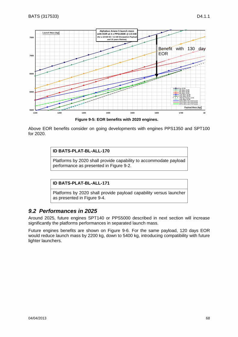
BATS (317533) D4.1.1
04/04/2013 68
Above EOR benefits consider on going developments with engines PPS1350 and SPT100 for 2020.
ID BATS-PLAT-BL-ALL-170
Platforms by 2020 shall provide capability to accommodate payload performance as presented in Figure 9-2.
ID BATS-PLAT-BL-ALL-171
Platforms by 2020 shall provide payload capability versus launcher as presented in Figure 9-4.
9.2 Performances in 2025 Around 2025, future engines SPT140 or PPS5000 described in next section will increase significantly the platforms performances in separated launch mass.
Future engines benefits are shown on Figure 9-6. For the same payload, 120 days EOR would reduce launch mass by 2200 kg, down to 5400 kg, introducing compatibility with future lighter launchers.
Alphabus Ariane 5 launch mass
with EOR at 4 x PPS1350E @ 2.5 kW
(for a 18 kW DC / 11 kW Dissipation Payload
and 15 years lifetime)
5500
6000
6500
7000
7500
1100 1200 1300 1400 1500 1600 1700 1800
Payload Mass (kg)
Launch Mass (kg)
No EOR30 days EOR60 days EOR90 days EOR120 days EOR130 days EOR700 kg Xenon Limit140 days EORCPS 42% min Fill FactorCPS 50% min Fill FactorCPS 36% min Fill Factor
Benefit with 130 day EOR
Figure 9-5: EOR benefits with 2020 engines.

BATS (317533) D4.1.1
04/04/2013 69
Figure 9-6: EOR benefits with 2025 engine.
Some of the key technology developments foreseen on NEOSAT program may offer sufficient growth potential in order to cover 26kW PL needs:
Power generation and supply
Thermal design
Electric Propulsion.
These developments provide indications of expected PF performances around 2025.
ID BATS-PLAT-EH-ALL-172
Platforms in 2025 shall be able to accommodate Payload DC power up to 26 kW
Benefit with 120 day EOR

BATS (317533) D4.1.1
04/04/2013 70
10 Regulatory Requirements
This chapter presents the rules derived from ITU radio Regulations, CEPT and National regulatory Authority.
The Radio Regulations of the ITU defines, in general terms, the management of the radio electric spectrum all over the world. However, some flexibility exists in the actual usage of the frequency bands at the regional and the national levels.
In Europe, at the regional level, the CEPT keeps the European Common Allocation (ECA) Table up to date with the long term goal of harmonizing the radio electric spectrum usage over the 46 member countries. Each country has at its disposal its own frequency allocation table managed by the National Regulatory Authority (NRA). Usually this table follows the Radio Regulations but can have, to a certain extent, some national specificity.
Within the framework of the BATS project, a study of the regulatory situation of the Ka and Q/V frequency bands is necessary to assess the spectrum availability for the satellite system as well as a study of the operating conditions of the latter in the chosen geographical area. In particular, the study aims at identifying and estimating the possible associated risks, i.e. the risks concerning the authorization requests to obtain the rights, from the national regulatory authority, to set the main stations.
This work is presented in detail in Annex G -.
The sections here below are a summary of the outcome of the detailed study.
10.1 Ka Band The Ka band is divided in three sub-bands: the shared civil Ka-band, the exclusive civil Ka-band and government Ka-band.
The sub-bands of interest in this study are the civil bands which are the frequency bands presented below:
Shared civil Ka-band:
o Downlink: 17.7-19.7 GHz.
o Uplink: 27.5-29.5 GHz.
Exclusive civil Ka-band (commercial band):
o Downlink: 17.3 – 17.7 GHz and 19.7 – 20.2 GHz
o Uplink: 29.5 – 30 GHz.
The government Ka band includes an additional 1 GHz allocated to the Fixed-Satellite Service (FSS) in the downlink and in the uplink (respectively 20.2 to 21.2 GHz and 30.0 to 31.0 GHz). However, this band is subject to specific agreements and particular operating conditions which are, among other things, decided within the NATO and within the armed forces headquarters. For these reasons, the government Ka-band won’t be taken into account in the analysis.
Ka band extension is detailed within the Annex F -.
Figure 10-1 and Figure 10-2 below explain entirely the segmentation of the civil Ka-band at the ECC level.

BATS (317533) D4.1.1
04/04/2013 71
ECC Regulatory framework
Ka-band segmentation for uplink frequencies
47.5504 MHz112 500 MHz 1000 MHz328.5 MHz 616 MHz 392 MHz
Teledesic Band MSS feeder
28.6 29.529.1
27.5 3127.8285 3029.528.8365 28.9485 29.452528.4445
Legend:
Figure 10-1: CEPT segmentation of the uplink bands from 27.5 to 31.0 GHz
ECC Regulatory framework
Ka-band segmentation for downlink frequencies
500 MHz 1000 MHz
19.6
MSS feederTeledesic Band
18.8 19.3
19.7 20.2 21.217.7 18.8 19.3
Legend:
Figure 10-2: CEPT segmentation of the downlink bands from 17.7 to 21.2 GHz
10.2 Q/V Band The Fixed-Satellite Service Q/V band is composed of 5 GHz for each direction, the uplink and the downlink. The downlink bands are contiguous contrary to the uplink bands. The bands’ segmentation is shown below:
Uplink
o 42.5-43.5 GHz
o 47.2-50.2 GHz
o 50.4-51.4 GHz
Downlink
o 37.5-42.5 GHz
Certain sub-parts of the uplink bands are also allocated to the Fixed-Satellite Service in the space-to-Earth direction in Region 1, namely: 47.5-47.9 GHz, 48.2-48.54 GHz and 49.44-50.2 GHz.
FSS exclusive allocation. Gateways and terminals – ECC exemption from individual licensing.
ECC designation for terrestrial services. Only coordinated FSS earth stations allowed
ECC exclusive designation for FSS – NO ECC exemption from individual licensing
ECC exclusive designation for FSS except in some CEPT countries
Governmental use in NATO countries
Coordinated FSS earth stations allowed in the whole shared band 27.5-29.5 GHz
FSS exclusive allocation. Gateways and uncoordinated terminals – ECC exemption from individual licensing
FSS/FS shared bands. No segmentation possible, application of mitigation techniques required
Governmental use in NATO countries
2000 MHz

BATS (317533) D4.1.1
04/04/2013 72
In the framework of his prospection work, NATO has found in the “NATO Joint Frequency Agreement” the Q/V band proper to the development of future military systems in the Fixed-Satellite Service and Mobile-Satellite Service. The harmonized NATO bands are consequently the band 39.5 to 40 GHz on the downlink and its associated band 50.4 to 51.4 GHz on the uplink.
Unlike the government Ka-band which is assimilated to military uses in Europe, the 39.5-40 GHz band and its associated band could be shared between military and civil applications.
The figures below show the sharing set by the ECC between the existing services in the Q/V
band for the uplink and downlink.
Figure 10-3: CEPT sharing of the Q/V band (uplink) from 42.5 to 51.4 GHz.
Figure 10-4: CEPT sharing of the Q/V band (downlink) from 37.5 to 42.5 GHz
10.3 Optical Communications There is no ITU Radio Regulation rule to be applied on optical communications.
10.4 Summary Table 10-1 sums up the regulation by distinguishing two distinct cases:
On one hand, the user terminals whose protection might be guaranteed only in the exclusive satellite bands;
On the other hand the gateways for which a successful coordination guarantees an acquired protection.

BATS (317533) D4.1.1
04/04/2013 73
Table 10-1: Summary of Regulatory requirements.
Frequency bands (GHz)
User terminals Gateways
Ka
Downlink bands
17.3 – 19.7
19.7 – 20.2
Uplink bands
27.5 – 27.8285
27.8285 – 28.4445
28.4445 – 28.8365
28.8365 – 29.4525
29.4525 – 29.5
29.5 – 30.0
Q/V
Downlink bands
37.5 – 39.5 no provision
39.5 – 40.5 no provision
40.5 – 42.5 no provision
Uplink bands
42.5 – 43.5 no provision
47.2 – 50.2 no provision
50.4 – 51.4 no provision
51.4 – 51.9 no provision
protected use possible
unprotected use
no allocation

BATS (317533) D4.1.1
04/04/2013 74
11 Deployment Requirements
The deployment requirements are to cover the BATS constellation consisting of both the baseline and the enhanced configurations. The time schedule of the project engineering phases is to be consistent with that of a large satellite platform as dictated by the selection of the choice of the extended Alphabus as baseline candidate.
Generally, an engineering life cycle of a project consists of the following [9]:
Phase A: Mission and operational analysis and feasibility
Phase B: Preliminary design and definition of requirements
Phase C: Detailed design to element level and start of implementation
Phase D: Development and technical + operational validation
Phase E: In orbit operations
Phase F: Mission termination
Availability of New Technologies
The technologies identified for the implementation of the mission are expected to have been developed and to be available in the given timeframe of the launch of the first satellites with the defined baseline configuration. In terms of the space segment, this will include equipment that have the capability to receive and convert signals within the Q/V band and optical frequency ranges. In addition, the extended Alphabus platform should be sufficiently developed in order to support the required repeater capability. In terms of the ground segment, this will include equipment that is able to transmit and process signals at these frequencies in order to establish the overall link with the space segment.
Before the contract signing for the first satellites of the BATS constellation, the maturity of new technologies and component design should be assessed and be deemed to have reached a satisfactory level, either to be complete or near completion. This assessment should only take a few months, especially given the limited number of suppliers that are expected to have worked on the necessary developments. To meet the launch date of 2020 for the first BATS satellites the research and development of the new technologies would need to be close to finalisation by the beginning of 2016.
If the new satellite equipment have not quite finished qualification at the time of contract signature then there should be some scope for the development to continue during the satellite design and development Phases A, B, C and beginning of D.
Based on the assumption that the relevant equipment technologies are available, there may still need to be some extra time in realising the implementation at payload level if the equipment has just completed development and have not been procured for other missions. As an example, the time allocated to test may need to be extended to ensure that the test systems are adequately in place to make performance measurements at the higher frequencies which is a new concept to satellite manufacture.
Space and Service Segment Design and Implementation Time Schedule – Baseline Configuration
The designing and testing of the first two satellites of the BATS constellation is anticipated to be at least four years. This is based on the assumption that there will be a lot of parallel design work and procurement activities. The launch of the second satellite is assumed to take place two months after the first satellite. This is based on the consideration that some activities such as repeater and spacecraft level testing would rely on reusing test equipment

BATS (317533) D4.1.1
04/04/2013 75
and test sites occupied by the first satellite. In addition, the availability of launch slots would be a big factor and would mean that the time between the launch of the first and second satellites could be extended. The launch of the first two satellites would be expected to take place by the end of 2020.
The designing and testing of a small satellite platform has an approximate duration of three years. For BATS, the selection is a large platform with new developments and a repeater capability incorporating large quantities of newly developed payload equipment, therefore a significant part of this is not likely to have flown. The fairly conservative minimum of four years would increase according to the level of contingency that would be required that is in turn based on the maturity of the platform and space equipment.
The launch of the two satellites is considered separately. However, depending on the launch capability at the time and the satellite integration and testing plan, it may be possible to launch the first two baseline satellites together and this may prove to be the more cost effective option.
The in orbit testing of the second baseline satellite should be less than for the first one as there should be more familiarity with the set-up of ground equipment and operations by that point and there may not be a need to test as many performance parameters.
The time schedule is detailed below for the first two satellites which are based on the baseline configuration.
ID BATS-DEP-BL-ALL-173
The Phase A (Mission and Operational Analysis) of the first two satellites shall start at the beginning of the first quarter of 2016, last 3 months, and complete at the end of the first quarter of 2016.
ID BATS-DEP-BL-ALL-174
The Phase B (Preliminary Design) of the first two satellites shall start at the beginning of the second quarter of 2016, last 6 months and finalise at the end of the third quarter of 2016.
ID BATS-DEP-BL-ALL-175
The Phase C (Detailed Design) of the first two satellites shall start at the beginning of the fourth quarter of 2016, last 12 months and finalise at the end of the third quarter of 2017.
ID BATS-DEP-BL-ALL-176
The contract signing by the operator shall happen during the first quarter of 2016.
ID BATS-DEP-BL-ALL-177
The Phase D (Development and Validation) of the first two satellites shall start at the beginning of the fourth quarter of 2017, last 2 years and finalise at the end of the third quarter of 2019.

BATS (317533) D4.1.1
04/04/2013 76
ID BATS-DEP-BL-ALL-178
The launch of the first baseline satellite shall happen in the first quarter of 2020. The launch of the second baseline satellite shall happen in the third quarter of 2020.
ID BATS-DEP-BL-ALL-179
The in orbit testing of the first satellite shall start in the first quarter of 2020 and last a maximum of two months.
ID BATS-DEP-BL-ALL-180
The service roll-out of the first satellite shall happen in either the second or the third quarter of 2020.
ID BATS-DEP-BL-ALL-181
The first satellite shall be fully operational by the end of the third quarter of 2020.
ID BATS-DEP-BL-ALL-182
The in orbit testing of the second satellite shall start in the third quarter of 2020 and last one month.
ID BATS-DEP-BL-ALL-183
The service roll-out of the second satellite shall happen in the fourth quarter of 2020.
ID BATS-DEP-BL-ALL-184
The second satellite shall be fully operational by the end of the fourth quarter of 2020.
Space and Service Segment Design and Implementation Time Schedule – Enhanced Configuration
In the case of the enhanced type of satellite, which is envisaged for launch by 2025, Phase A would need to assess current additional capacity requirements, taking into account the provision of service of the baseline constellation of BATS satellites already launched in the timeframe 2020-2025. Phase A is extended for the enhanced satellite as quite a detailed piece of analysis would need to be completed to optimise the constellation throughput. The start of Phase A is based on the requirement to have an enhanced satellite ready for launch in 2025.
Phase D of the project would be shorter than for the first two satellites. This is based on the assumption that the development and testing sites from the previous two satellites will be available and there will be operational experience using similar advanced technologies. The
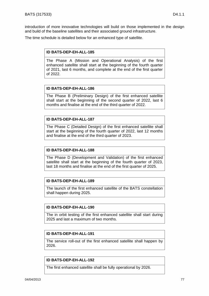
BATS (317533) D4.1.1
04/04/2013 77
introduction of more innovative technologies will build on those implemented in the design and build of the baseline satellites and their associated ground infrastructure.
The time schedule is detailed below for an enhanced type of satellite.
ID BATS-DEP-EH-ALL-185
The Phase A (Mission and Operational Analysis) of the first enhanced satellite shall start at the beginning of the fourth quarter of 2021, last 6 months, and complete at the end of the first quarter of 2022.
ID BATS-DEP-EH-ALL-186
The Phase B (Preliminary Design) of the first enhanced satellite shall start at the beginning of the second quarter of 2022, last 6 months and finalise at the end of the third quarter of 2022.
ID BATS-DEP-EH-ALL-187
The Phase C (Detailed Design) of the first enhanced satellite shall start at the beginning of the fourth quarter of 2022, last 12 months and finalise at the end of the third quarter of 2023.
ID BATS-DEP-EH-ALL-188
The Phase D (Development and Validation) of the first enhanced satellite shall start at the beginning of the fourth quarter of 2023, last 18 months and finalise at the end of the first quarter of 2025.
ID BATS-DEP-EH-ALL-189
The launch of the first enhanced satellite of the BATS constellation shall happen during 2025.
ID BATS-DEP-EH-ALL-190
The in orbit testing of the first enhanced satellite shall start during 2025 and last a maximum of two months.
ID BATS-DEP-EH-ALL-191
The service roll-out of the first enhanced satellite shall happen by 2026.
ID BATS-DEP-EH-ALL-192
The first enhanced satellite shall be fully operational by 2026.

BATS (317533) D4.1.1
04/04/2013 78
Following the launch and service roll-out of the first enhanced satellite, additional satellites will be manufactured and launched based on analysis conducted from 2021 onwards of the future traffic demand and the requirements of meeting the service provision with more capacity in particular areas. It is anticipated that once the first enhanced satellite is in place, further enhanced satellites can be produced in a quicker time frame if they are based on exactly the same design.
Ground Segment System and Service Design and Implementation Time Schedule – Baseline and Enhanced Configuration
Inevitably, the design and implementation time schedules of the space and ground segments are strictly correlated. They should follow the same engineering life cycle as for the space segment and this is from the start of Phase A to being ready to commence service in-orbit, with all the ground segment components in place and sufficiently validated for operation.
We assume that the Phase A of the ground segment starts at the same time as the space segment, which is the beginning of the first quarter of 2016, and also lasts 3 months. On the contrary, the Phase B and Phase C of the ground segment shall last less than the respective phases in the space segment design. The development and validation of the ground segment, Phase D, at the beginning can be split in two parts: GW antenna and facility. As detailed in Section 4, the GWs shall be located in existing Earth station facilities (when possible) in order to reduce the complexity and cost of developing and deploying the system. We assume that the facilities can be in any case developed in parallel as they will be located in different sites around Europe. In the case of developing a new facility, after two years of Phase D, the two parts (antenna and facility) are joined together and the installation and integration phase begins. This testing will last 3 months and it is followed by the in-orbit testing of both the space and ground segments. The mission operation (Phase E) of both space and ground segments shall start at the same time, last the same duration and finalize by the end of the satellites’ lifetime (Phase F).
ID BATS-DEP-BL-ALL-193
The ground segment’s Phase A (Mission and Operational Analysis) shall start in the beginning of the first quarter of 2016, last 3 months, and complete at the end of the first quarter of 2016.
ID BATS-DEP-BL-ALL-194
The Phase B (Preliminary Design) of the ground segment shall start at the beginning of the second quarter of 2016, last 3 months, and complete at the end of the second quarter of 2016.
ID BATS-DEP-BL-ALL-195
The ground segment’s Phase C (Detailed Design) shall start in the beginning of the third quarter of 2016, last six months, and complete at the end of the fourth quarter of 2016.
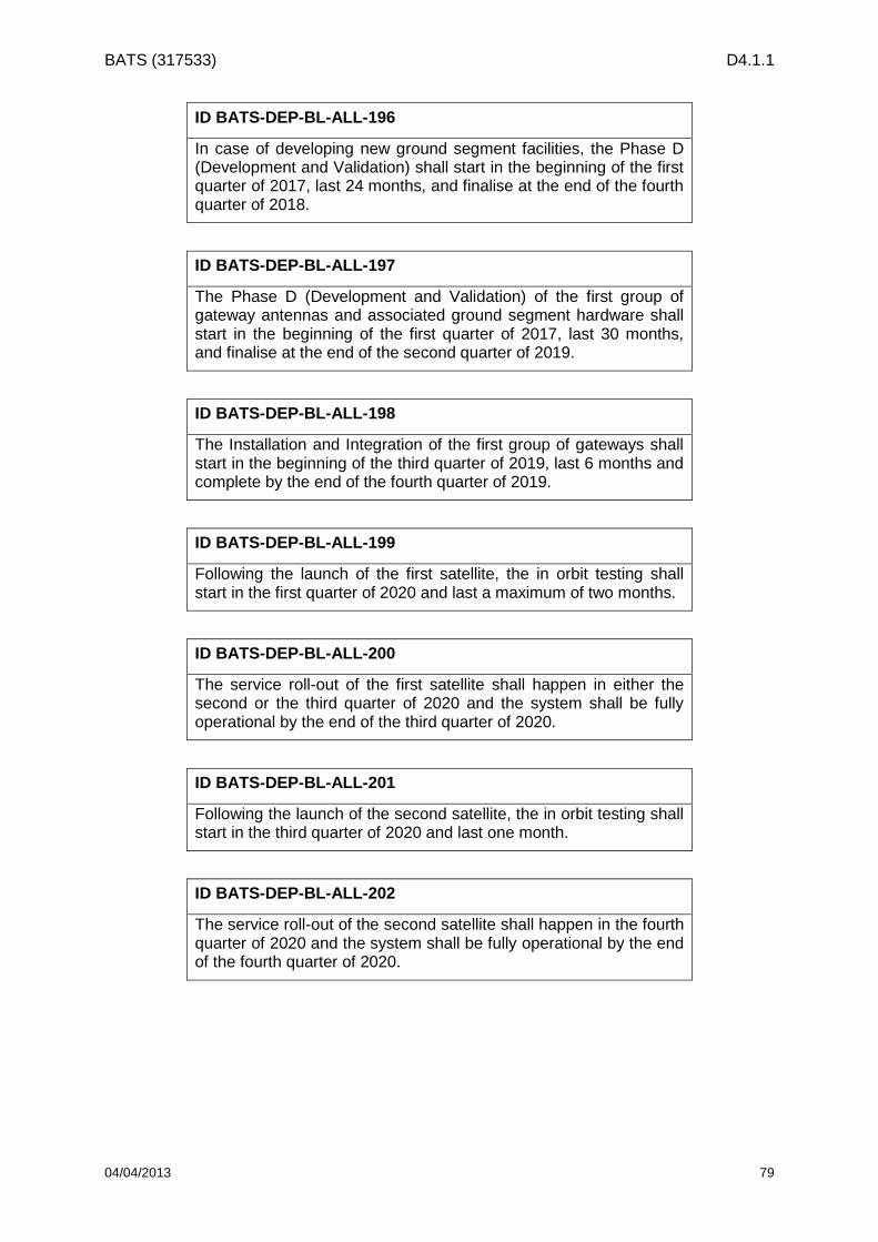
BATS (317533) D4.1.1
04/04/2013 79
ID BATS-DEP-BL-ALL-196
In case of developing new ground segment facilities, the Phase D (Development and Validation) shall start in the beginning of the first quarter of 2017, last 24 months, and finalise at the end of the fourth quarter of 2018.
ID BATS-DEP-BL-ALL-197
The Phase D (Development and Validation) of the first group of gateway antennas and associated ground segment hardware shall start in the beginning of the first quarter of 2017, last 30 months, and finalise at the end of the second quarter of 2019.
ID BATS-DEP-BL-ALL-198
The Installation and Integration of the first group of gateways shall start in the beginning of the third quarter of 2019, last 6 months and complete by the end of the fourth quarter of 2019.
ID BATS-DEP-BL-ALL-199
Following the launch of the first satellite, the in orbit testing shall start in the first quarter of 2020 and last a maximum of two months.
ID BATS-DEP-BL-ALL-200
The service roll-out of the first satellite shall happen in either the second or the third quarter of 2020 and the system shall be fully operational by the end of the third quarter of 2020.
ID BATS-DEP-BL-ALL-201
Following the launch of the second satellite, the in orbit testing shall start in the third quarter of 2020 and last one month.
ID BATS-DEP-BL-ALL-202
The service roll-out of the second satellite shall happen in the fourth quarter of 2020 and the system shall be fully operational by the end of the fourth quarter of 2020.

BATS (317533) D4.1.1
04/04/2013 80
12 References
[1] European Commission, “European Broadband: Investing in digitally driven growth”, COM (2010) 472, Brussels.
[2] Cisco, “The Zettabyte Era”, White paper 2012.
[3] BATS, “D2.2 Broadband Technologies, Capabilities and Challenges (Release 2)”, January 2013.
[4] BATS, “D2.1 Definition of Broadband Services Requirements and Quality of Experience (Release 2)”, January 2013.
[5] Ofcom, “Infrastructure report 2012 Update
[6] Point Topic, “BB-MED TN3.1, Expected Broadband demand in ‘ESA Study Countries’ in 2020”, March 2012.
[7] TERASAT - Approaching the terabit/s satellite: a system study, “TN3.3 Preliminary Mission Requirements (Release 3)”, May 2012.
[8] MSBN – Techniques and technologies for ultra high throughput multi-spot beam networks, “TN1100: Scenarios Definition”, July 2012.
[9] ECSS Secretariat (ESA-ESTEC), “Space Project Management – Project Phasing and Planning”, ECSS-M-30A, April 1996.
[10] Alcatel-Lucent, “Is symmetrical bandwidth a myth or a must?”, http://www2.alcatel-lucent.com/techzine/is-symmetrical-bandwidth-a-myth-or-a-must/, October 2012.
[11] ETSI EN 301 545-2 V1.1.1 (2012-01): Digital Video Broadcasting (DVB); Second Generation DVB Interactive Satellite System (DVB-RCS2); Part 2: Lower Layers for Satellite standard.

BATS (317533) D4.1.1
04/04/2013 81
Annex A - Complete List of Requirements (Assembled)
Throughout this document the reader will encounter all the individual requirements that will be used as a baseline in the following activities of the project. Each requirement is formalized with a unique ID that is compiled by 5 parts as follows:
ID: ACT-TYP-SC-FEED-NUM
where
ACT identifies the name of the activity, in this report BATS for Broadband Access via integrated Terrestrial and Satellite systems.
TYP provides the type of requirement and could get the following values: SER for service requirements, SYS for system requirements, SAT for space segment requirements, GW for gateway requirements, UT for user terminal, PLAT for platform requirements, NCM for network control and management, REG for regulatory, and DEP for deployment requirements.
SC specifies the type of scenario that the requirement refers to. It could obtain the following values BL for the baseline configuration, EH for the enhanced configuration and ALL for both configurations.
FEED specifies the frequency band of the feeder link in the corresponding scenario. It could obtain the values QV for the Q/V-band feeder link configuration, OPT for the optical frequency feeder link configuration, and ALL for both configurations.
NUM is just an increasing number of 3 digits to ensure the particularity of the requirement.
All requirements shall be understood based on the following rule:
The word shall is used to indicate mandatory requirements strictly to be followed in order to conform to the requirements and from which no deviation is permitted (shall equals is required to).
The word should is used to indicate that among several possibilities one is recommended as particularly suitable, without mentioning or excluding others; or that a certain course of action is preferred but not necessarily required; or that (in the negative form) a certain course of action is deprecated but not prohibited (should equals is recommended that).
The word may is used to indicate a course of action permissible within the limits of the standard (may equals is permitted).
The word can is used for statements of possibility and capability, whether material, physical, or causal (can equals is able to).
A.1 Service Requirements
ID BATS-SER-ALL-ALL-001
The BATS satellite constellation shall be able to support a peak downlink and uplink data rates of 100 Mbps and 20 Mbps per household.

BATS (317533) D4.1.1
04/04/2013 82
ID BATS-SER-BL-ALL-002
The BATS baseline satellite constellation shall be able to provide an average unicast downlink and uplink data rates of 889 kbps and 111 kbps per residential household.
ID BATS-SER-BL-ALL-003
The BATS baseline satellite constellation shall be able to provide an average unicast downlink and uplink data rates of 752 Kbps and 188 kbps per business site.
ID BATS-SER-EH-ALL-004
The BATS enhanced satellite constellation shall be able to provide an average unicast downlink and uplink data rates of 3.42 Mbps and 428 kbps per residential household.
ID BATS-SER-EH-ALL-005
The BATS enhanced satellite constellation shall be able to provide an average unicast downlink and uplink data rates of 1.87 Mbps and 578 kbps per business site.
ID BATS-SER-ALL-ALL-006
The BATS service shall take into account the application QoE requirements described in BATS deliverable D2.1.
ID BATS-SER-ALL-ALL-007
The link availability of the BATS constellation shall not be less than 99.0% for multicast and 99.6% unicast services (for the 98% of the total coverage).
ID BATS-SER-ALL-ALL-008
In the case of optical feeder links, the unicast availability in BATS-SER-ALL-ALL-007 can be reduced to 99.4% link availability subject to the proof of a considerable cost benefit
ID BATS-SER-ALL-ALL-009
The BATS constellation shall be able to serve at least 7.56 million households and 0.51 million businesses in the EU27 plus Turkey.
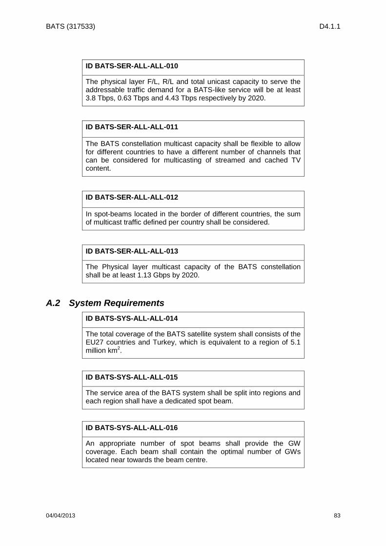
BATS (317533) D4.1.1
04/04/2013 83
ID BATS-SER-ALL-ALL-010
The physical layer F/L, R/L and total unicast capacity to serve the addressable traffic demand for a BATS-like service will be at least 3.8 Tbps, 0.63 Tbps and 4.43 Tbps respectively by 2020.
ID BATS-SER-ALL-ALL-011
The BATS constellation multicast capacity shall be flexible to allow for different countries to have a different number of channels that can be considered for multicasting of streamed and cached TV content.
ID BATS-SER-ALL-ALL-012
In spot-beams located in the border of different countries, the sum of multicast traffic defined per country shall be considered.
ID BATS-SER-ALL-ALL-013
The Physical layer multicast capacity of the BATS constellation shall be at least 1.13 Gbps by 2020.
A.2 System Requirements
ID BATS-SYS-ALL-ALL-014
The total coverage of the BATS satellite system shall consists of the EU27 countries and Turkey, which is equivalent to a region of 5.1 million km2.
ID BATS-SYS-ALL-ALL-015
The service area of the BATS system shall be split into regions and each region shall have a dedicated spot beam.
ID BATS-SYS-ALL-ALL-016
An appropriate number of spot beams shall provide the GW coverage. Each beam shall contain the optimal number of GWs located near towards the beam centre.

BATS (317533) D4.1.1
04/04/2013 84
ID BATS-SYS-ALL-ALL-017
The GWs shall be located in existing Earth Station sites across the EU27 and Turkey as far as possible.
ID BATS-SYS-BL-ALL-018
The first two satellites of the baseline configuration by 2020 shall serve half the coverage each.
ID BATS-SYS-EH-ALL-019
The first satellite of the enhanced satellite mission in 2025 shall cover the 30% of the whole EU27 plus Turkey land area.
ID BATS-SYS-ALL-ALL-020
The BATS satellites shall have one transparent forward payload and one transparent return payload. The BATS enhanced satellite based on an Optical feeder link may consider a “partially regenerative” payload model (subject to further analysis and trade-off).
ID BATS-SYS-ALL-ALL-021
The BATS satellites shall have a cellular multibeam coverage in the user link and a multibeam coverage in the feeder link.
ID BATS-SYS-ALL-ALL-022
The BATS satellite constellation shall consist of several baseline and enhanced S/Cs positioned in GEO orbit.
ID BATS-SYS-BL-ALL-023
The cluster of two collocated satellites corresponding to the first deployment phase of the baseline mission shall be positioned at the orbital slot in 13⁰E.
ID BATS-SYS-ALL-ALL-024
The subsequent BATS satellites (baseline and enhanced) shall be positioned between 30⁰W and 35⁰E.
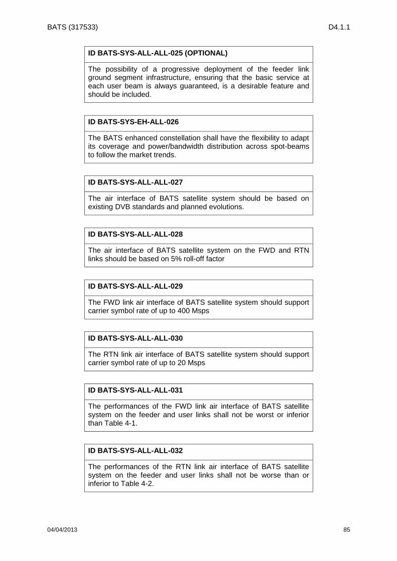
BATS (317533) D4.1.1
04/04/2013 85
ID BATS-SYS-ALL-ALL-025 (OPTIONAL)
The possibility of a progressive deployment of the feeder link ground segment infrastructure, ensuring that the basic service at each user beam is always guaranteed, is a desirable feature and should be included.
ID BATS-SYS-EH-ALL-026
The BATS enhanced constellation shall have the flexibility to adapt its coverage and power/bandwidth distribution across spot-beams to follow the market trends.
ID BATS-SYS-ALL-ALL-027
The air interface of BATS satellite system should be based on existing DVB standards and planned evolutions.
ID BATS-SYS-ALL-ALL-028
The air interface of BATS satellite system on the FWD and RTN links should be based on 5% roll-off factor
ID BATS-SYS-ALL-ALL-029
The FWD link air interface of BATS satellite system should support carrier symbol rate of up to 400 Msps
ID BATS-SYS-ALL-ALL-030
The RTN link air interface of BATS satellite system should support carrier symbol rate of up to 20 Msps
ID BATS-SYS-ALL-ALL-031
The performances of the FWD link air interface of BATS satellite system on the feeder and user links shall not be worst or inferior than Table 4-1.
ID BATS-SYS-ALL-ALL-032
The performances of the RTN link air interface of BATS satellite system on the feeder and user links shall not be worse than or inferior to Table 4-2.

BATS (317533) D4.1.1
04/04/2013 86
ID BATS-SYS-ALL-ALL-033
Multicast shall be handled by the satellite system.
ID BATS-SYS-ALL-ALL-034
If a satellite spot beam covers several countries, the sum of the multicast traffic demand per country shall be handled by the satellite spot beam.
ID BATS-SYS-ALL-ALL-035
The targeted link availability of the multicast traffic shall be higher than 99%.
ID BATS-SYS-ALL-ALL-036
Adaptive Coding and Modulation (ACM) should be applied on the transmitted multicast traffic.
ID BATS-SYS-ALL-ALL-037
The ACM MODCOD selection shall take into account the link budget performances of all connected/active users within a satellite spot beam.
ID BATS-SYS-ALL-ALL-038
The multicast traffic should be transmitted in the exclusive FSS band.
ID BATS-SYS-ALL-ALL-039
The multicast traffic shall be transmitted through the user satellite multi-spot beam (no implementation of linguistic beams)
ID BATS-SYS-ALL-ALL-040
The multicast traffic should be transmitted on one carrier per spot beam, time multiplexed with unicast traffic
ID BATS-SYS-ALL-ALL-041
The user terminal side should implement two receivers/demodulators: one for the multicast traffic (which is only available in one carrier) and another one for unicast traffic (when the unicast traffic is not on the same carrier as the multicast traffic)

BATS (317533) D4.1.1
04/04/2013 87
A.3 Space Segment Requirements
ID BATS-SAT-ALL-ALL-042
The design operational lifetime shall be at least 15 years.
ID BATS-SAT-ALL-ALL-043
The satellite shall be compatible with initial placement into geostationary transfer orbit (GTO) by at least two launcher vehicles.
ID BATS-SAT-ALL-ALL-044
The selected launchers shall offer a 5 meter diameter fairing.
ID BATS-SAT-ALL-ALL-045
In case of Electrical Orbit Raising strategy for transfer phase, the maximum duration of the EOR phase shall be less than 120 days; such requirement applies to Baseline and Enhanced configurations.
ID BATS-SAT-ALL-ALL-046
The Beam pointing error guaranteed to the mission will be less than 0.025°.
ID BATS-SAT-ALL-ALL-047
On the FWD link, the downlink frequency band shall be based on the 17.3 – 20.2 GHz frequency band.
ID BATS-SAT-ALL-ALL-048
Part of the exclusive band shall be included in each user spot beam.
ID BATS-SAT-ALL-ALL-049
On the RTN link, the uplink frequency band shall be based on the bands 27.5 – 27.8285 GHz, 28.4445 – 28.9485 GHz and 29.4525 – 30 GHz.

BATS (317533) D4.1.1
04/04/2013 88
ID BATS-SAT-ALL-ALL-050
On both user uplink and downlink, the circular polarisation shall be used.
ID BATS-SAT-ALL-ALL-051
On any given uplink and downlink user spot beam, orthogonal polarisation shall be used.
ID BATS-SAT-ALL-ALL-052
The minimum satellite EIRP density on the FWD link shall comply with Figure 5-2.
ID BATS-SAT-ALL-ALL-053
The minimum payload G/T achievable on the RTN uplink service area shall be higher than 20 dB/K over 95% of the coverage.
ID BATS-SAT-ALL-ALL-054
On the FWD link, the transponder should be operated in ALC (Automatic Level Control) mode.
ID BATS-SAT-ALL-ALL-055
On the RTN link, the transponder should be operated in FGM (Fixed Gain Mode).
ID BATS-SAT-ALL-ALL-056
A general rule for the active equipment (LNAs, tubes) shall be to include at least 15% redundancy.
ID BATS-SAT-ALL-ALL-057
A general rule for the active equipment (LNAs, tubes) shall be to include at least 15% redundancy.
ID BATS-SAT-ALL-ALL-058
The satellite feeder link payload should support the N+P site diversity solution.

BATS (317533) D4.1.1
04/04/2013 89
ID BATS-SAT-ALL-ALL-059
In terms of overall link budget performances in clear sky conditions, the feeder link shall not degrade the median user link budget by more than 1.5dB.
ID BATS-SAT-ALL-ALL-060
In terms of link availability, the feeder link shall support a link availability higher than 99.9%, in line with 99.7% user link availability to achieve 99.6% overall link availability), with a link budget that could be degraded with respect to the link budget in clear sky conditions. This degradation shall not decrease the related user beam capacity by more than 25 %.
ID BATS-SAT-ALL-ALL-061
A general rule for the active equipment (LNAs, tubes) shall be to include at least 15% of redundancy.
ID BATS-SAT-ALL-QV-062
On the FWD uplink, the V-band frequency to be considered for a R/F feeder solution shall be included in the [42.5 - 43.5] GHz, [47.2 - 50.2] GHz and [50.4 - 51.4] GHz bands, allocated to FSS by the ITU.
ID BATS-SAT-ALL-QV-063
On the RTN downlink, the Q-band spectrum to be considered is the [37.5 - 42.5] GHz band.
ID BATS-SAT-ALL-QV-064
The space segment associated to Q/V band feeder link options will involve transparent signal processing on the forward and on the return links, in both 2020 and 2025 timeframes.
ID BATS-SAT-ALL-QV-065
The feeder-to-user beam connectivity should ensure the implementation of N+P gateway diversity.

BATS (317533) D4.1.1
04/04/2013 90
ID BATS-SAT-ALL-QV-066
The satellite gateway Q/V receive antennas shall be able to operate in both LHCP and RHCP polarizations.
ID BATS-SAT-ALL-QV-067
For the RTN link, the feeder section shall ensure the channelization and the amplification of the signals issued from the user link receive section.
ID BATS-SAT-ALL-QV-068
The RTN link user-to-gateway beam connectivity shall be congruent with the FWD link connectivity.
ID BATS-SAT-BL-ALL-069
The selected approach for the 2020 satellites is to maximise the raw satellite system capacity, allocating the same bandwidth and power to all user beams.
ID BATS-SAT-BL-ALL-070
Two satellites operated over the same orbital slot shall be designed, assuming a target launch by 2020.
ID BATS-SAT-BL-ALL-071
The targeted orbital slot is 13°East, geosynchronous orbital location.
ID BATS-SAT-BL-ALL-072
The satellite design of the Baseline configuration shall be compatible of the platform capability as detailed in Section 9.1.
ID BATS-SAT-BL-ALL-073
The targeted platform shall be the Alphabus Extended platform. Further description is provided in Section 9.1.

BATS (317533) D4.1.1
04/04/2013 91
ID BATS-SAT-BL-ALL-074
The satellite payload shall provide a continuous multi-spot beam coverage area on the user link (FWD and RTN) over the EU27 countries plus Turkey.
ID BATS-SAT-BL-ALL-075
FWD and RTN user link satellite spot beams shall be congruent.
ID BATS-SAT-BL-ALL-076
A regular 4-colour frequency reuse scheme should be implemented on both the FWD link and the RTN link.
ID BATS-SAT-BL-ALL-077
On the FWD downlink, the frequency plan should comply with Figure 5-5, allocating one colour per user spot beam
ID BATS-SAT-BL-ALL-078
On the RTN downlink, the frequency plan should comply with Figure 5-6, allocating one colour per user spot beam
ID BATS-SAT-BL-ALL-079
The satellite payload feeder link coverage shall be within the service area, i.e. the EU27 countries plus Turkey.
ID BATS-SAT-BL-ALL-080
The required number of gateway sites to support the operation of both satellites shall be minimised. The reuse of gateway sites for the operation of both satellites shall be considered. To allow such operation, it is assumed that both satellites may be operated with a maximum orbital separation of 0.3°.
ID BATS-SAT-BL-OPT-081
The payload model for the baseline configuration with optical feeders shall be transparent.
BATS (317533) D4.1.1
04/04/2013 92
ID BATS-SAT-BL-OPT-082
For optical links, the redundancy is handled at two levels:
• For the opto-electronic part, the power amplifiers shall be redundant internally (additional pumping diodes shall be used to cover failures)
• For the electronic part, conventional redundancy scheme shall be applied.
ID BATS-SAT-EH-ALL-083
The selected approach for the 2025 satellite(s) is to provide coverage flexibility in order to provide the service in hot demand areas. In this scenario, a satellite should only cover the 30% of the whole EU27 plus Turkey land area.
ID BATS-SAT-EH-ALL-084
It is assumed that part of the coverage area of the satellite would be identified at the beginning of the program, then the remaining coverage area being flexibly defined in orbit (also called post launch flexibility).
ID BATS-SAT-EH-ALL-085
The satellite(s) will be operated at an orbital slot different from the 2020 satellites, allowing frequency and gateway site reuse.
ID BATS-SAT-EH-ALL-086
The first enhanced satellite operated shall be designed assuming a target launch by 2025.
ID BATS-SAT-EH-ALL-087
The targeted orbital slot ranges from 30° West to 35° East, geosynchronous orbital location. In the following of the project, it is proposed to perform the analysis at one orbital location, e.g. 30°East.
ID BATS-SAT-EH-ALL-088
The satellite design of the Enhanced configuration shall be compatible of the platform capability as detailed in Section 9.2.
BATS (317533) D4.1.1
04/04/2013 93
ID BATS-SAT-EH-ALL-089
The targeted platform is the evolution of the Alphabus Extended platform through the introduction of Neosat technologies.
ID BATS-SAT-EH-ALL-090
The satellite payload shall cover 30% of the service area on the user link (FWD and RTN) of the EU27 countries plus Turkey.
ID BATS-SAT-EH-ALL-091
Part of the 30% coverage area will be fixed and defined at the beginning of the program; the remaining part shall be flexibly defined in orbit in order to meet the traffic demand.
ID BATS-SAT-EH-ALL-092
The cost of flexibility has to be less than the 10% in terms of capacity reduction compared to a fixed configuration by launch
ID BATS-SAT-EH-ALL-093
The satellite payload feeder link coverage shall be based as much as possible on the gateway sites used for the 2020 satellites in order to minimise the deployment of new gateway sites.
ID BATS-SAT-EH-ALL-094
The gateway sites used for the 2020 satellites shall be reused as much as possible in order to minimise the deployment of new gateway sites.
ID BATS-SAT-EH-OPT-095
The payload model for the enhanced configuration with optical feeders shall be either transparent or partly regenerative.
A.4 Gateway Requirements
ID BATS-GW-ALL-QV-096
Each Q/V feeder station shall handle at least 4 spots in emission and reception

BATS (317533) D4.1.1
04/04/2013 94
ID BATS-GW-ALL-QV-097
The gateway frequency range for the transmission and reception sections shall be compliant with the feeder link frequency plan.
ID BATS-GW-ALL-QV-098
The Q/V gateway antenna shall support circular right and left polarization. The cross-polarization isolation shall be better than 27 dB
ID BATS-GW-ALL-QV-099
The transmit gain shall be greater than 65 dBi at 47.5 GHz
ID BATS-GW-ALL-QV-100
The gateway antenna diagram shall comply with the ITU masks.
ID BATS-GW-ALL-QV-101
The gateway power amplification stage shall be able to provide a maximum output power of 500 W per access when the HPAs are operated at saturation.
ID BATS-GW-ALL-QV-102
The station shall implement uplink power control function.
ID BATS-GW-ALL-QV-103
G/T including the pointing losses shall be greater than 37dBi/K at 37.5GHz and 20° elevation.
ID BATS-GW-ALL-OPT-104
The OGW shouldbe able to receive or transmit in the range of the optical C band and L band (around 1.55 µm) from one on satellite terminal.

BATS (317533) D4.1.1
04/04/2013 95
ID BATS-GW-ALL-OPT-105
The maximum size of the telescopes should be lower than 500 mm.
ID BATS-GW-ALL-OPT-106
Each OGW should consider one of the following options:
• One single transmit/receive telescope
• Separate single transmit and receive telescope
• Separate multiple aperture transmit and receive telescope
ID BATS-GW-ALL-OPT-107
The total throughput is split between several operational OGW.
For site diversity, redundant terminal will be either local or regional:
• The operational OGW shall be located at a distance > TBC between them.
• The redundant local OGW shall be located within a distance < 300 km from the operational terminals.
• The redundant regional OGW shall be located within a distance > 500 km from the operational terminals.
ID BATS-GW-ALL-OPT-108
The OGW shall be able to communicate with the satellite terminal with an elevation angle down to 20 deg.
ID BATS-GW-ALL-OPT-109
Handover related to the optical link availability (cloud, atmosphere, etc.) between gateways shall be performed by switching the relevant traffic from the operational OGWs to the selected ones (under clear sky conditions) with minimization of the interruption of the service.
ID BATS-GW-ALL-OPT-110
The following eye safety standard is applicable and shall be conformed to: the European Comity of Normalization (CEN) defined in its second version of the Norm EN 60825-1 the level of Maximal Permit Exposure (EMP) to lasers. This level is based on the values of the International Commission on Non-Ionizing Radiation protection (ICNIRP)

BATS (317533) D4.1.1
04/04/2013 96
A.5 User Terminal Requirements
ID BATS-UT-ALL-ALL-111
The UT shall cost no more than today’s UT (i.e., 300 euros).
ID BATS-UT-EH-ALL-112
By the time the project reaches very large numbers of users the UT shall cost 75% of today’s UT.
ID BATS-UT-ALL-ALL-113
The UT shall have a combined design MTBF in excess of 10 years.
ID BATS-UT-ALL-ALL-114
The UT shall be designed to minimise the risk of epidemic failure.
ID BATS-UT-ALL-ALL-115
The UT shall be designed to be installed as simply as possible to reduce time required to complete the task.
ID BATS-UT-ALL-ALL-116
The UT should be designed to allow self-installation where allowed.
ID BATS-UT-ALL-ALL-117
The UT shall provide a web interface to allow the end user to check UT and service status; and to assist the more advanced user in installing their own system.
ID BATS-UT-ALL-ALL-118
The UT shall be designed so that a maximum transmit pointing loss of 0.5dB can be readily achieved.
ID BATS-UT-ALL-ALL-119
The UT shall be configured by the main NMS.

BATS (317533) D4.1.1
04/04/2013 97
ID BATS-UT-ALL-ALL-120
The UT shall be designed so that it can’t be configured by the end user.
ID BATS-UT-EH-ALL-121
The UT shall be designed that it will not cause interference to others due to a faulty installation.
ID BATS-UT-ALL-ALL-122
The UT shall be designed so that the installation is as unobtrusive as reasonably possible.
ID BATS-UT-ALL-ALL-123
Consideration shall be given to using a single low cost co-axial cable between indoor and outdoor equipment for power, control transmit and receive carriers.
ID BATS-UT-ALL-ALL-124
The UT shall be powered by a single power plug
ID BATS-UT-ALL-ALL-125
The UT shall have a maximum equivalent diameter of no more than 74cm.
ID BATS-UT-EH-ALL-126
Ideally the UT should have a maximum equivalent diameter of no more than 70cm.
ID BATS-UT-BL-ALL-127
The UT shall have an EIRP at least 50.5dBW at 30GHz under maximum de-pointing.
BATS (317533) D4.1.1
04/04/2013 98
ID BATS-UT-EH-ALL-128
The UT should have an EIRP of at least 51.5dBW at 30GHz under maximum de-pointing.
ID BATS-UT-BL-ALL-129
The UT shall have a G/T at least 19dB/K in clear sky at 30 deg elevation at 20GHz.
ID BATS-UT-EH-ALL-130
The UT should have a G/T at least 20dB/K in clear sky at 30 deg elevation at 20GHz.
ID BATS-UT-ALL-ALL-131
The UT shall support the unicast peak data rate and sustained data rates specified in Section 3.
ID BATS-UT-ALL-ALL-132
The UT shall support operation in the Ka-band frequency ranges specified in Section 5.
ID BATS-UT-ALL-ALL-133
The UT shall provide at least one Gig-E connection and an L band output covering the full RF receive range (1.5GHz) specified in Section 5.
ID BATS-UT-ALL-ALL-134
The UT shall support IPv6. Support of IPv4 is left as optional feature.
ID BATS-UT-ALL-ALL-135
The UT shall support the UT frequency bands specified in Section 5.

BATS (317533) D4.1.1
04/04/2013 99
ID BATS-UT-ALL-ALL-136
The UT shall support circular polarisation with orthogonal transmit and receive polarisations.
ID BATS-UT-ALL-ALL-137
The UT shall allow simple conversion between polarisation (for example between RHCP and LHCP).
ID BATS-UT-ALL-ALL-138
The UT shall support forward link carriers up to 400Msps.
ID BATS-UT-ALL-ALL-139
The UT should support forward link carriers conforming to DVB-Sx as specified in Section 4 and may support other waveforms.
ID BATS-UT-ALL-ALL-140
The UT shall support return link carriers up to 20 Msps.
ID BATS-UT-ALL-ALL-141
The UT should support return link carriers conforming to DVB-RCS2 and its evolution as specified in Section 4 and may support other waveforms.
ID BATS-UT-ALL-ALL-142
The UT shall be able to perform an intelligent interference management, to handle possible interference from terrestrial networks.
ID BATS-UT-ALL-ALL-143
The UT shall draw no more than 40W prime power.

BATS (317533) D4.1.1
04/04/2013 100
ID BATS-UT-ALL-ALL-144
Ideally the UT should have mechanisms to reduce idle power consumption when not transmitting to the satellite.
ID BATS-UT-ALL-ALL-145
The UT shall conform to all relevant European national and international specifications for operation in EU27 and Turkey.
ID BATS-UT-ALL-ALL-146
Ideally UT will conform to other International specifications such as those demanded by the FCC/UL/ANSI.
ID BATS-UT-ALL-ALL-147
The UT shall conform to industry standards for accessing Ka band geosynchronous capacity.
A.6 NCC/NMS Requirements
ID BATS-NCM-ALL-ALL-148
A main NCC/NMS shall be the responsible of the overall network control and management. In addition, each GW shall be equipped with their local NCC/NMS.
ID BATS-NCM-ALL-ALL-149
The main NCC/NMS shall be located in the centre of the coverage (i.e., central Europe) and specifically in a country without national conflicts or propensity for natural disasters.
ID BATS-NCM-ALL-ALL-150
The GW NCC shall be responsible of the synchronisation and signalling with the user terminals under its control and the implementation of fade mitigation techniques such as ULPC and ACM.

BATS (317533) D4.1.1
04/04/2013 101
ID BATS-NCM-ALL-ALL-151
The GW NMS shall be responsible of the resource and user terminal allocation, connection authorisation, frequency planning, failure and alarm monitoring, user information storing, etc.
ID BATS-NCM-ALL-ALL-152
All pairs of NCC and NMS shall be collocated in the same facility.
ID BATS-NCM-ALL-ALL-153
The main NCC/NMS shall coordinate with the GWs’ NCC/NMS to ensure a seamless switchover when implementing any smart site diversity technique.
ID BATS-NCM-ALL-ALL-154
The GW NMS shall monitor and test all the GW components and receive information such as ACM settings, congestion, bandwidth requirements, latencies, updated link fading status, etc.
ID BATS-NCM-ALL-ALL-155
All feeder and user terminal components shall send their information to the main NCC/NMS at least once every 10s in nominal conditions.
ID BATS-NCM-ALL-ALL-156
In case a malfunction or extreme fading event is detected, an alarm signal has to reach the main NMS in less than 0.5 seconds in order to counteract the triggering phenomenon.
ID BATS-NCM-ALL-ALL-157
During the switchover from one GW to another, the main NMS shall inform all the components involved in less than 0.5 seconds after the switching decision is taken.
ID BATS-NCM-ALL-ALL-158
The main NCC/NMS shall guarantee that no packet will be permanently loss during a GW switchover.

BATS (317533) D4.1.1
04/04/2013 102
ID BATS-NCM-ALL-ALL-159
A GPS receiver is needed in all feeder link components to ensure time synchronisation.
ID BATS-NCM-ALL-ALL-160
In case of failure or underperformance of the GPS system, a local oscillator with an atomic clock shall be able to keep the network synchronised until the GPS functionality is re-established.
ID BATS-NCM-ALL-ALL-161
The GW-NMS shall ensure a correct user information management and storing and guarantee the correct system management by interacting with the main NMS.
ID BATS-NCM-ALL-ALL-162
The GW-NMSs have to make sure that all connected elements have authorisation.
ID BATS-NCM-ALL-ALL-163
The main NCC/NMS shall be able to communicate with all feeder link components individually via a backbone network based on optical fibres.
ID BATS-NCM-ALL-ALL-164
All the critical equipment at the main NCC/NMS facility shall be fully redundant.
ID BATS-NCM-ALL-ALL-165
All NCC/NMS facilities shall be scalable to be able to support a larger system in the future.
ID BATS-NCM-ALL-ALL-166
All NCC/NMS facilities shall comply with the ISO27000 series of security standards.

BATS (317533) D4.1.1
04/04/2013 103
A.7 Platform Requirements
ID BATS-PLAT-BL-ALL-167
Platforms in 2020 shall be able to accommodate Payload DC power up to 22 kW
ID BATS-PLAT-ALL-BL-168
Platforms in 2020 shall be able to accommodate Payload dissipation up to 19 kW.
ID BATS-PLAT-BL-ALL-169
Platforms by 2020 shall provide permanent 3 axis attitude determination to cope with disturbances generated by large antennas.
ID BATS-PLAT-BL-ALL-170
Platforms by 2020 shall provide capability to accommodate payload performance as presented in Figure 9-2.
ID BATS-PLAT-BL-ALL-171
Platforms by 2020 shall provide payload capability versus launcher as presented in Figure 9-4.
ID BATS-PLAT-EH-ALL-172
Platforms in 2025 shall be able to accommodate Payload DC power up to 26 kW
A.8 Deployment Requirements
ID BATS-DEP-BL-ALL-173
The Phase A (Mission and Operational Analysis) of the first two satellites shall start at the beginning of the first quarter of 2016, last 3 months, and complete at the end of the first quarter of 2016.

BATS (317533) D4.1.1
04/04/2013 104
ID BATS-DEP-BL-ALL-174
The Phase B (Preliminary Design) of the first two satellites shall start at the beginning of the second quarter of 2016, last 6 months and finalise at the end of the third quarter of 2016.
ID BATS-DEP-BL-ALL-175
The Phase C (Detailed Design) of the first two satellites shall start at the beginning of the fourth quarter of 2016, last 12 months and finalise at the end of the third quarter of 2017.
ID BATS-DEP-BL-ALL-176
The contract signing by the operator shall happen during the first quarter of 2016.
ID BATS-DEP-BL-ALL-177
The Phase D (Development and Validation) of the first two satellites shall start at the beginning of the fourth quarter of 2017, last 2 years and finalise at the end of the third quarter of 2019.
ID BATS-DEP-BL-ALL-178
The launch of the first baseline satellite shall happen in the first quarter of 2020. The launch of the second baseline satellite shall happen in the third quarter of 2020.
ID BATS-DEP-BL-ALL-179
The in orbit testing of the first satellite shall start in the first quarter of 2020 and last a maximum of two months.
ID BATS-DEP-BL-ALL-180
The service roll-out of the first satellite shall happen in either the second or the third quarter of 2020.
ID BATS-DEP-BL-ALL-181
The first satellite shall be fully operational by the end of the third quarter of 2020.

BATS (317533) D4.1.1
04/04/2013 105
ID BATS-DEP-BL-ALL-182
The in orbit testing of the second satellite shall start in the third quarter of 2020 and last one month.
ID BATS-DEP-BL-ALL-183
The service roll-out of the second satellite shall happen in the fourth quarter of 2020.
ID BATS-DEP-BL-ALL-184
The second satellite shall be fully operational by the end of the fourth quarter of 2020.
ID BATS-DEP-EH-ALL-185
The Phase A (Mission and Operational Analysis) of the first enhanced satellite shall start at the beginning of the fourth quarter of 2021, last 6 months, and complete at the end of the first quarter of 2022.
ID BATS-DEP-EH-ALL-186
The Phase B (Preliminary Design) of the first enhanced satellite shall start at the beginning of the second quarter of 2022, last 6 months and finalise at the end of the third quarter of 2022.
ID BATS-DEP-EH-ALL-187
The Phase C (Detailed Design) of the first enhanced satellite shall start at the beginning of the fourth quarter of 2022, last 12 months and finalise at the end of the third quarter of 2023.
ID BATS-DEP-EH-ALL-188
The Phase D (Development and Validation) of the first enhanced satellite shall start at the beginning of the fourth quarter of 2023, last 18 months and finalise at the end of the first quarter of 2025.
ID BATS-DEP-EH-ALL-189
The launch of the first enhanced satellite of the BATS constellation shall happen during 2025.
BATS (317533) D4.1.1
04/04/2013 106
ID BATS-DEP-EH-ALL-190
The in orbit testing of the first enhanced satellite shall start during 2025 and last a maximum of two months.
ID BATS-DEP-EH-ALL-191
The service roll-out of the first enhanced satellite shall happen by 2026.
ID BATS-DEP-EH-ALL-192
The first enhanced satellite shall be fully operational by 2026.
ID BATS-DEP-BL-ALL-193
The ground segment’s Phase A (Mission and Operational Analysis) shall start in the beginning of the first quarter of 2016, last 3 months, and complete at the end of the first quarter of 2016.
ID BATS-DEP-BL-ALL-194
The Phase B (Preliminary Design) of the ground segment shall start at the beginning of the second quarter of 2016, last 3 months, and complete at the end of the second quarter of 2016.
ID BATS-DEP-BL-ALL-195
The ground segment’s Phase C (Detailed Design) shall start in the beginning of the third quarter of 2016, last six months, and complete at the end of the fourth quarter of 2016.
ID BATS-DEP-BL-ALL-196
In case of developing new ground segment facilities, the Phase D (Development and Validation) shall start in the beginning of the first quarter of 2017, last 24 months, and finalise at the end of the fourth quarter of 2018.
ID BATS-DEP-BL-ALL-197
The Phase D (Development and Validation) of the first group of gateway antennas and associated ground segment hardware shall start in the beginning of the first quarter of 2017, last 30 months, and finalise at the end of the second quarter of 2019.

BATS (317533) D4.1.1
04/04/2013 107
ID BATS-DEP-BL-ALL-198
The Installation and Integration of the first group of gateways shall start in the beginning of the third quarter of 2019, last 6 months and complete by the end of the fourth quarter of 2019.
ID BATS-DEP-BL-ALL-199
Following the launch of the first satellite, the in orbit testing shall start in the first quarter of 2020 and last a maximum of two months.
ID BATS-DEP-BL-ALL-200
The service roll-out of the first satellite shall happen in either the second or the third quarter of 2020 and the system shall be fully operational by the end of the third quarter of 2020.
ID BATS-DEP-BL-ALL-201
Following the launch of the second satellite, the in orbit testing shall start in the third quarter of 2020 and last one month.
ID BATS-DEP-BL-ALL-202
The service roll-out of the second satellite shall happen in the fourth quarter of 2020 and the system shall be fully operational by the end of the fourth quarter of 2020.

BATS (317533) D4.1.1
04/04/2013 108
Annex B - Air Interface Performances
B.1 Air Interface
This section aims at defining the air interface to be considered for the BATS satellite systems.
The air interface shall be based on DVB standards:
DVB-Sx standard on the FWD link, Sx meaning the next generation of DVB-S2 standard,
DVB-RCS2 standard on the RTN link as the baseline scenario. In the frame of WP4.4, evolution of the RCS2 standard would be considered: depending on the outcome of the analysis, it could be considered as an alternate solution of the RCS2 standard.
B.1.1 FWD Link
B.1.1.1 Air Interface Performances
In 2013, in the frame of the DVB, the Technical Module S2 works for the enhancement of the DVB-S2 standard. There are two different targets:
First target, called “DVB-S2 evolution”. The objective are:
o to improve the current DVB-S2 standard by 15 to 30% “without a fundamental change to the complexity and structure of DVB-S2”,
o to support the transmission of very high carrier symbol rates (target between 200 to 400 Msps) over wideband transponder (250MHz to 500 MHz).
It is planned to get a finalized specification by the end 2013.
Second target, called “DVB-S2 revolution”. The objective is to define a new standard with new technologies to better answer to evolution of markets and introduction of new services
The planning for the definition of a new standard is not defined yet. A study mission report is to be submitted by mid-2013 to help the definition of related Commercial Requirements. A target date for the definition of the new standard may be 2015 at the earliest.
Knowing that the DVB-S2 standard will evolve in the near future (including the evolution and the revolution targets), but standardization being still on-going, it is proposed to consider the following assumptions for the definition of the air interface performances to be considered on the FWD link for 2020 timeframe:
Tighter roll-off factor: it is proposed to consider 5%. It is already available on the commercial market (Novelsat, Newtec, …) and tighter roll-off factor is targeted by the evolution of the S2 standard,
Higher carrier symbol rate: it is proposed to consider carrier symbol rate up to 400 Msps,
Improved spectral efficiency: talking about spectral efficiency in terms of bits per symbol (i.e. excluding improvement due to tighter roll-off, which is covered above), it can be expected that at least 10% improvement wrt current DVB-S2 standard (normal frame with pilot symbols) would be achieved by 2020.
In terms of modem performances, it is proposed to consider the following approach:

BATS (317533) D4.1.1
04/04/2013 109
The document “A. Bertella, V. Mignone, B. Sacco, M. Tabone, “Laboratory evaluation of DVB-S2 state-of-the-art equipment”, EBU Technical Review, Jan. 2007”, provides some test measurement performed on DVB-S2 modem equipment available in 2006. This would provide a reference for typical modem implementation margin for equipment available on the market in 2006.
As a range of modem implementation margin is available, it is proposed to consider as reference performances the average between the minimum and the maximum modem implementation margin for each modulation format. It leads to:
o QPSK modulation: margin varies from 0.2 to 0.6 dB. The reference performance is then equal to 0.4 dB,
o 8PSK modulation: margin varies from 0.2 to 0.9 dB. The reference performance is then equal to 0.55 dB,
o 16APSK modulation: margin varies from 0.3 to 1.3 dB. The reference performance is then equal to 0.8 dB,
o 32APSK modulation: margin varies from 1.3 to 1.7 dB. The reference performance is then equal to 1.5 dB.
It is proposed to consider an improvement factor for modem equipment to be available by 2020 timeframe (as tests were performed with equipment available in 2006). A reduction of 25% of the modem implementation margin is targeted (already available for commercial equipment for some MODCOD), leading to the following modem implementation margin:
o QPSK modulation: 0.3 dB,
o 8PSK modulation: 0.41 dB,
o 16APSK modulation: 0.6 dB,
o 32APSK modulation: 1.13 dB.
In terms of evolution of the air interface performances from 2020 to 2025 timeframe:
It is difficult to anticipate,
It would depend on the timing when “DVB-S2 revolution” would be ready (there may not be any improvement in the period 2020 – 2025),
The additional potential gain would remain low as 10% improvement wrt the DVB-S2 specification is already considered for the 2020 air interface performances, which would be very close to Shannon limit.
It is proposed to keep the same air interface performances in 2020 and 2025
Potential improvement may come from interference cancelation techniques that will be investigated in frame of the WP4.4 and WP4.5.
Note: the baseline air interface performances have been defined. However, if potential techniques, for example for gateway site diversity (Satellite-switched TDMA) or for flexibility (beam hopping) would require some adaptation of the air interface, then it would be considered. However, the required adaptations with respect to the baseline air interface scenario would have to be investigated for each of the proposed technique.
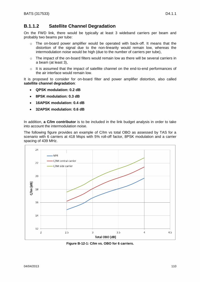
BATS (317533) D4.1.1
04/04/2013 110
B.1.1.2 Satellite Channel Degradation
On the FWD link, there would be typically at least 3 wideband carriers per beam and probably two beams per tube:
o The on-board power amplifier would be operated with back-off. It means that the distortion of the signal due to the non-linearity would remain low, whereas the intermodulation noise would be high (due to the number of carriers per tube),
o The impact of the on-board filters would remain low as there will be several carriers in a beam (at least 3),
o It is assumed that the impact of satellite channel on the end-to-end performances of the air interface would remain low.
It is proposed to consider for on-board filter and power amplifier distortion, also called satellite channel degradation:
QPSK modulation: 0.2 dB
8PSK modulation: 0.3 dB
16APSK modulation: 0.4 dB
32APSK modulation: 0.6 dB
In addition, a C/Im contributor is to be included in the link budget analysis in order to take into account the intermodulation noise.
The following figure provides an example of C/Im vs total OBO as assessed by TAS for a scenario with 6 carriers at 418 Msps with 5% roll-off factor, 8PSK modulation and a carrier spacing of 439 MHz.
Figure B-12-1: C/Im vs. OBO for 6 carriers.

BATS (317533) D4.1.1
04/04/2013 111
B.1.1.3 ACM Loop Margin
On the FWD link, Adaptive Coding and Modulation will be implemented. The related ACM loop margin should be defined. It is proposed to consider the following assumptions:
A typical value of ACM loop time response of 1 s,
SNR measurement accuracy: assuming that the terminal would be able to average the measurements in order to improve the accuracy (at the high targeted symbol rates, this should be possible), a SNR measurement accuracy of 0.5 dB is assumed
Fade slope: following the ITU-R recommendation P.1623-1, it is possible to compute the fade slope exceeded for a given percentage of time as a function of the rain attenuation. DLR has provided the following table coming from the recommendation:
Assuming that adaptive margin is to be implemented (margin is low in clear weather and the margin is increased in rainy conditions), it is proposed to consider a maximum fade slope of:
o 0.1 dB/s in clear sky,
o 0.25 dB/s in rainy condition (max rain attenuation over the coverage area for 99.7% at 20.2 GHz: 4.2 dB)
This would lead to the following ACM loop margin, considering that ACM loop margin = measurement accuracy + delay * fade slope:
ACM loop margin (clear sky) = 0.5 dB + 1s * 0.1dB/s = 0.6 dB,
ACM loop margin (rainy) = 0.5 dB + 1s * 0.25dB/s = 0.75 dB
B.1.1.4 Overall End-to-End Air Interface Performances
Taking into account the contributors described in the previous sub-sections, the following table summarizes the overall end-to-end air interface performances to be considered for BATS satellite systems (2020 and 2025).

BATS (317533) D4.1.1
04/04/2013 112
Modulation Coding Rate MODCOD
Spectral
efficiency as per
DVB-S2
(bit/symbol)
Spectral efficiency for
DVB-Sx assuming 10%
of improvement factor
(bit/symbol)
Theoretical
Es/No DVB-S2
Performances
Modem
Margin as per
2007 tests
Improvement
factor on modem
margin: 25%
Satellite
Channel
Degradation
ACM
Variable
Margin
Overall
Es/No
QPSK 1/4 1 0.479 0.526 -2.35 dB 0.40 dB 0.30 dB 0.20 dB 0.0 dB -1.85 dB
QPSK 1/3 2 0.641 0.705 -1.24 dB 0.40 dB 0.30 dB 0.20 dB 0.6 dB -0.14 dB
QPSK 2/5 3 0.771 0.848 -0.30 dB 0.40 dB 0.30 dB 0.20 dB 0.6 dB 0.80 dB
QPSK 1/2 4 0.965 1.062 1.00 dB 0.40 dB 0.30 dB 0.20 dB 0.6 dB 2.10 dB
QPSK 3/5 5 1.160 1.276 2.23 dB 0.40 dB 0.30 dB 0.20 dB 0.6 dB 3.33 dB
QPSK 2/3 6 1.291 1.420 3.10 dB 0.40 dB 0.30 dB 0.20 dB 0.6 dB 4.20 dB
QPSK 3/4 7 1.452 1.597 4.03 dB 0.40 dB 0.30 dB 0.20 dB 0.6 dB 5.13 dB
QPSK 4/5 8 1.549 1.704 4.68 dB 0.40 dB 0.30 dB 0.20 dB 0.6 dB 5.78 dB
QPSK 5/6 9 1.615 1.777 5.18 dB 0.40 dB 0.30 dB 0.20 dB 0.6 dB 6.28 dB
8-PSK 3/5 12 1.740 1.914 5.50 dB 0.55 dB 0.41 dB 0.30 dB 0.6 dB 6.81 dB
8-PSK 2/3 13 1.936 2.129 6.62 dB 0.55 dB 0.41 dB 0.30 dB 0.6 dB 7.93 dB
8-PSK 3/4 14 2.178 2.395 7.91 dB 0.55 dB 0.41 dB 0.30 dB 0.6 dB 9.22 dB
16-APSK 2/3 18 2.575 2.832 8.97 dB 0.80 dB 0.60 dB 0.40 dB 0.6 dB 10.57 dB
16-APSK 3/4 19 2.896 3.186 10.21 dB 0.80 dB 0.60 dB 0.40 dB 0.6 dB 11.81 dB
16-APSK 4/5 20 3.090 3.400 11.03 dB 0.80 dB 0.60 dB 0.40 dB 0.6 dB 12.63 dB
16-APSK 5/6 21 3.222 3.544 11.61 dB 0.80 dB 0.60 dB 0.40 dB 0.6 dB 13.21 dB
32-APSK 3/4 24 3.623 3.986 12.73 dB 1.50 dB 1.13 dB 0.60 dB 0.6 dB 15.06 dB
32-APSK 4/5 25 3.866 4.253 13.64 dB 1.50 dB 1.13 dB 0.60 dB 0.6 dB 15.97 dB
32-APSK 5/6 26 4.031 4.434 14.28 dB 1.50 dB 1.13 dB 0.60 dB 0.6 dB 16.61 dB
32-APSK 8/9 27 4.303 4.733 15.69 dB 1.50 dB 1.13 dB 0.60 dB 0.6 dB 18.02 dB
32-APSK 9/10 28 4.357 4.793 16.05 dB 1.50 dB 1.13 dB 0.60 dB 0.6 dB 18.38 dB
QPSK
8-PSK
16APSK
32APSK
B.1.2 RTN Link
B.1.2.1 Air Interface Performances
The DVB-RCS2 standard has just been issued. The time to generate a new version of the standard is longer than for DVB-S2 (DVB-RCS issued in 2000, DVB-RCS2 in 2012).
Therefore, it is not clear if a new version would be available by 2020 or 2025.
It is proposed to keep the current DVB-RCS2 standard air interface performances as it is.
However, the following evolutions are foreseen for 2020 timeframe:
Tighter roll-off factor: as considered for the FWD link, it is assumed that a tighter roll-off factor would be available. It is proposed to consider 5%
Higher carrier symbol rate: it is proposed to consider carrier symbol rate up to 20 Msps, in order to allow reaching the 20 Mbps target,
Modem implementation margin: the document “ETSI EN 301 545-2, “Digital Video Broadcasting (DVB); Second Generation DVB Interactive Satellite System (DVB-RCS2); Guidelines for Implementation and Use of LLS” provides an example of modem implementation margin. It is proposed to consider those values
Note: In the frame of WP4.4, evolutions of the DVB-RCS2 standard will be investigated. Depending on the conclusion of the analysis, the considered air interface performances may be adapted.
B.1.2.2 Satellite Channel Degradation
On the RTN link, there would be many carriers per beam, the bandwidth of a carrier being rather small when compared to the bandwidth allocated per beam. The impact of the satellite channel on the end-to-end performances would be limited, keeping in mind that the RTN link remains a burst mode type of access: it is considered more sensitive to degradation than the FWD link.
It is proposed to consider the following satellite channel degradation performances:
QPSK modulation: 0.2 dB
8PSK modulation: 0.4 dB
16QAM modulation: 0.8 dB
Table B-12-1: FWD Link Air Interface Performances in Clear Sky.

BATS (317533) D4.1.1
04/04/2013 113
B.1.2.3 FMT Loop Margin
On the RTN link, Fade Mitigation Techniques will be implemented. The related FMT loop margin should be defined. It is proposed to consider the following assumptions:
A typical FMT loop time response value of 1.5 s (higher than on the FWD due to processing and signalling),
SNR measurement accuracy:
o The sources of error on the SNR measurement on the RTN link are more numerous than on the FWD link (interference variation on a burst-to-burst basis, terminal power stability, …) and their contribution is more likely to be higher (measurement on burst with a lower number of samples, interference impact, …).
o Assuming that some rules for burst scheduling (to minimise the interference) and advanced algorithm (to perform accurate estimation of SNR) would be implemented, a target value of SNR measurement accuracy of 0.5 dB is assumed (challenging)
Fade slope: the table provided on the FWD link is applicable on the RTN link. Assuming that adaptive margin is to be implemented, it is proposed to consider a maximum fade slope of:
o 0.15 dB/s in clear sky,
o 0.45 dB/s in rainy condition (max rain attenuation over the coverage area for 99.7% at 30 GHz: 8.7 dB)
This would lead to the following FMT loop margin, considering that FMT loop margin = measurement accuracy + delay * fade slope:
FMT loop margin (clear sky) = 0.5 dB + 1.5s * 0.15dB/s = 0.7 dB,
FMT loop margin (rainy) = 0.5 dB + 1.5s * 0.45dB/s = 1.2 dB
B.1.2.4 Overall End-to-End Air Interface Performances
Taking into account the contributors described in the previous sub-sections, the following table summarizes the overall end-to-end air interface performances to be considered for BATS satellite systems (2020 and 2025).
Table B-12-2: RTN Link Air Interface Performances in Clear Sky.

BATS (317533) D4.1.1
04/04/2013 114
Annex C - Telecom System Analysis for Multicast Support
This annex deals with the investigation of several telecom system solutions for the support of multicast traffic transmission.
Taking into account the geographical distribution of the multicast traffic demand defined in Section 3 as well as the multicast traffic requirements summarized in Section 4, the following solutions could handle multicast traffic transmission:
1. Implementation of a dedicated satellite payload (repeater and antenna) providing linguistic beam coverage,
2. Usage of the multi-spot beam coverage:
a. Repetition of the multicast traffic on each carrier within a beam (single receiver on terminal side),
b. Transmission of the multicast traffic on a single carrier within a beam (dual receiver on terminal side),
c. Transmission of the multicast traffic on a dedicated carrier. This scenario is not further considered in the following: it is applicable only if multicast link availability is critical (requiring boosted EIRP carriers).
Solution 1): Dedicated Payload
For this solution, linguistic beams shall be defined. The following figure provides an example of 9 linguistic beams over EU27+Turkey.
A Broadcast Satellite Service (BSS) band is exclusively allocated to satellite in Ka-band: the band 21.4-22 GHz. It could be a candidate frequency band for the transmission of the multicast traffic in case a dedicated satellite payload is envisaged.
Another solution is to allocated part of the 17.3-20.2 GHz band for FSS to the transmission of the multicast traffic.
Both options are illustrated in the following figure.
Figure C-12-2: Example of linguistic beam coverage.

BATS (317533) D4.1.1
04/04/2013 115
The impacts of the dedicated satellite payload solution are:
Impact on the Unicast system capacity:
o In case of the usage of the FSS band only, the band allocated to the multicast carriers cannot be used for unicast traffic, implying a loss of bandwidth for unicast traffic,
o If the BSS band is used, then the unicast traffic could benefit from the whole FSS band,
Impact on the terminal:
o In case of the usage of the FSS band only, there is a need to receive in both polarizations. Indeed, the spot beams and the linguistic beams are not congruent: it is most likely that the unicast traffic will be received in a given polarization while the multicast traffic will be received potentially in the opposite polarization,
o In case of the usage of the FSS band only, there is a need to implement two receivers:
Two LNBs are required as unicast and multicast traffic can be transmitted in two different polarizations,
Two demodulators are required as unicast and multicast traffic are transmitted on two different carriers,
o If the BSS band is used, then it would have impact on the design/performances of the terminal antenna as the frequency range that the terminal shall support (potentially from 17.3 up to 22 GHz) is very wide.
Impact on the feeder link:
o The required feeder link bandwidth to support the total multicast traffic is minimized (multicast traffic only transmitted once per linguistic beam),
o There is a need for specific equipment to support the transmission of the multicast carriers,
Figure C-12-3: Example of frequency band to be used for the transmission of the multicast traffic in the case of a dedicated satellite payload solution.

BATS (317533) D4.1.1
04/04/2013 116
o Note: this solution does not reduce the number of GWs as only a very small amount of bandwidth is saved per GW. However, this saved bandwidth cannot be re-used for unicast traffic (too small to be interesting)
Impact on the payload:
o There is a need for a dedicated antenna solution
e.g. 9 linguistic beams could be handled (antenna ~1 to 1.5 m)
o There is a need for additional tubes, with probably higher power than for unicast
The size of the tube would depends on:
Link availability target
Selected MODCOD
Number/size of linguistic beams
The power used for multicast would not be available for the unicast traffic (potential loss of capacity on unicast traffic if the satellite solution is power limited)
Solution 2-a): No Dedicated Payload – Multicast traffic transmitted in each carrier of each user spot
In this scenario, the multicast traffic is repeated and time multiplexed within each TDM carrier transmitted in a user spot beam. There is not any dedicated payload: the multicast traffic is handled through the spot beams.
This allows to not change the terminal design to handle multicast traffic (no need for dual receivers/demodulators)
An example of the frequency plan in case of a 4-colour reuse scheme is provided in the following figure (only one polarisation is shown, thus 2 colours).
The impacts of this solution are:
Impact on the Unicast system capacity:
Figure C-12-4: Frequency plan example with multicast traffic transmitted in each carrier of each user spot beam.

BATS (317533) D4.1.1
04/04/2013 117
o The capacity dedicated to the support of multicast traffic is not available for unicast (on the uplink and on the downlink)
Impact on the terminal:
o No impact on the design
Impact on the feeder link:
o No impact on the design
Impact on the payload:
o No impact on the design
Solution 2-b): No Dedicated Payload – Multicast traffic transmitted in only one carrier of each user spot
In this scenario, the multicast traffic is repeated and time multiplexed within only one carrier per spot beam. There is not any dedicated payload: the multicast traffic is handled through the spot beams.
An example of the frequency plan in case of a 4-colour reuse scheme is provided in the following figure (only one polarisation is shown, thus 2 colours).
The impacts of this solution are:
Impact on the Unicast system capacity:
o The capacity dedicated to the support of multicast traffic is not available for unicast (on the uplink and on the downlink), but the impact is reduced wrt the scenario 2-a) as the multicast traffic is only transmitted once per spot beam (instead of on each carrier within a spot beam)
Impact on the terminal:
o Two demodulators are required: one for the unicast and one for the multicast
Impact on the feeder link:
o No impact on the design
Impact on the payload:
o No impact on the design
Figure C-12-5: Frequency plan example with multicast traffic transmitted in only one carrier of each user spot beam.

BATS (317533) D4.1.1
04/04/2013 118
Preliminary quantitative assessment of the impact of multicast support on unicast capacity
In order to provide some quantitative figure of the impact of the multicast transmission over the unicast capacity, a scenario is considered which remains an illustrative example:
For the dedicated payload solution, it is assumed:
o 9 linguistic beams with 100 Mbps of multicast traffic per beam (optimistic assumptions based on average demand per linguistic: in fact, some beams would require more than that, driving the need for bandwidth for this solution)
o QPSK ¾ (it would depends on targeted link availability, payload power…)
A 72 Msps carrier is needed per linguistic beam to handle the multicast traffic (or 82,5 MHz including the roll-off and on-board filtering guard band)
For the non-dedicated payload solution, it is assumed:
o Taking the ESA Terabit study as an example (260 spot beams over EU27), the multicast traffic has been aggregated per spot beam taking into account the multicast traffic demand defined per country. If a spot beam covers two countries, the sum of the multicast traffic demand of each country is considered. The result is shown in the following figure.
The related average multicast traffic demand per spot beam is equal to 73 Mbps
o In order to derive the required carrier symbol rate needed to support the multicast traffic per spot beam, ACM mechanism over many users should be considered
o The ACM mechanism over many users consists in selecting the most robust MODCOD over the active users
Figure C-12-6: Multicast traffic demand per user spot beam (based on beam layout of Terabit study).
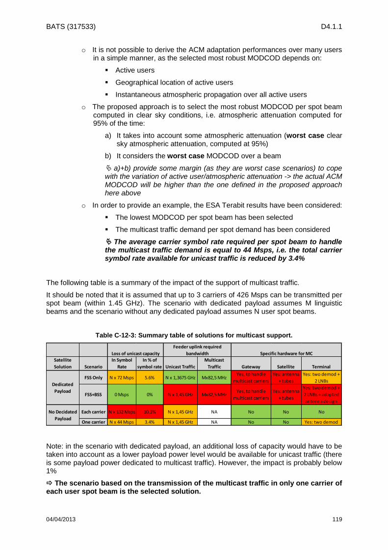
BATS (317533) D4.1.1
04/04/2013 119
o It is not possible to derive the ACM adaptation performances over many users in a simple manner, as the selected most robust MODCOD depends on:
Active users
Geographical location of active users
Instantaneous atmospheric propagation over all active users
o The proposed approach is to select the most robust MODCOD per spot beam computed in clear sky conditions, i.e. atmospheric attenuation computed for 95% of the time:
a) It takes into account some atmospheric attenuation (worst case clear sky atmospheric attenuation, computed at 95%)
b) It considers the worst case MODCOD over a beam
a)+b) provide some margin (as they are worst case scenarios) to cope with the variation of active user/atmospheric attenuation -> the actual ACM MODCOD will be higher than the one defined in the proposed approach here above
o In order to provide an example, the ESA Terabit results have been considered:
The lowest MODCOD per spot beam has been selected
The multicast traffic demand per spot demand has been considered
The average carrier symbol rate required per spot beam to handle the multicast traffic demand is equal to 44 Msps, i.e. the total carrier symbol rate available for unicast traffic is reduced by 3.4%
The following table is a summary of the impact of the support of multicast traffic.
It should be noted that it is assumed that up to 3 carriers of 426 Msps can be transmitted per spot beam (within 1.45 GHz). The scenario with dedicated payload assumes M linguistic beams and the scenario without any dedicated payload assumes N user spot beams.
Table C-12-3: Summary table of solutions for multicast support.
Loss of unicast capacity
Feeder uplink required
bandwidth Specific hardware for MC
Satellite
Solution Scenario
In Symbol
Rate
In % of
symbol rate Unicast Traffic
Multicast
Traffic Gateway Satellite Terminal
FSS Only N x 72 Msps 5.6% N x 1,3675 GHz Mx82,5 MHzYes, to handle
multicast carriers
Yes: antenna
+ tubes
Yes: two demod +
2 LNBs
FSS+BSS 0 Msps 0% N x 1,45 GHz Mx82,5 MHzYes, to handle
multicast carriers
Yes: antenna
+ tubes
Yes: two demod +
2 LNBs + adapted
antenna design
Each carrier N x 132 Msps 10.3% N x 1,45 GHz NA No No No
One carrier N x 44 Msps 3.4% N x 1,45 GHz NA No No Yes: two demod
Dedicated
Payload
No Decidated
Payload
Note: in the scenario with dedicated payload, an additional loss of capacity would have to be taken into account as a lower payload power level would be available for unicast traffic (there is some payload power dedicated to multicast traffic). However, the impact is probably below 1%
The scenario based on the transmission of the multicast traffic in only one carrier of each user spot beam is the selected solution.
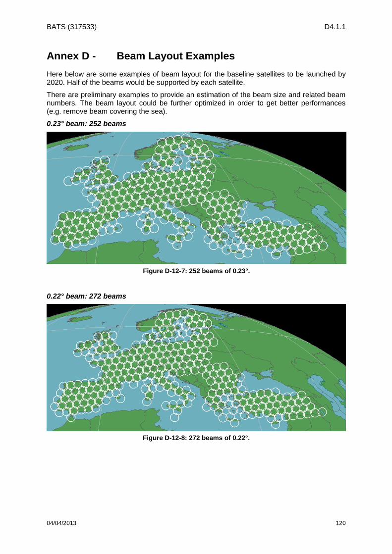
BATS (317533) D4.1.1
04/04/2013 120
Annex D - Beam Layout Examples
Here below are some examples of beam layout for the baseline satellites to be launched by 2020. Half of the beams would be supported by each satellite.
There are preliminary examples to provide an estimation of the beam size and related beam numbers. The beam layout could be further optimized in order to get better performances (e.g. remove beam covering the sea).
0.23° beam: 252 beams
0.22° beam: 272 beams
Figure D-12-7: 252 beams of 0.23°.
Figure D-12-8: 272 beams of 0.22°.

BATS (317533) D4.1.1
04/04/2013 121
0.21° beam: 295 beams
0.20° beam: 319 beams
Figure D-12-9: 295 beams of 0.21°.
Figure D-12-10: 319 beams of 0.20°.

BATS (317533) D4.1.1
04/04/2013 122
Summary
The following table and figure summarizes the different configurations.
Table D-12-4: Summary of the relation between size and number of beams.
Beam Size Number of Beams
0.23° 252
0.22° 272
0.21° 295
0.20° 319
Figure D-12-11: Relation between size and number of beams.
BATS (317533) D4.1.1
04/04/2013 123
Annex E - Post-launch flexibility: some options (2025 timeframe)
It is desired to consider a space segment development in 2025 timeframe, with a view to offer complementary satellite transmission capacity to the 2020 timeframe satellites over particular regions identified as “hotspots”. In this regard, the additional satellite payload and beam layout shall be designed to fit as much as possible the capacity to the demand, possibly through non homogeneous resource allocation over this reduced coverage. It is also desirable to study the possibility to flexibly modify – to some degree – the satellite capacity allocation over the coverage in operational conditions. This option, referred to in the following as “post-launch flexibility”, is considered as valuable as long as it does not imply a decrease of more than 10% of the total satellite capacity w.r.t a fixed solution by launch. The focus is put on the forward link in the following.
A preliminary review of technical options to provide “post-launch” flexibility is provided here. Their compliance with the abovementioned system and payload specifications will be more deeply analyzed in later study phases.
Post-launch flexibility basically consists in the flexible allocation of part of the satellite resources over the coverage. The “resources” subject to re-allocation depend on the considered options. In the options considered below, the flexibility is mostly related to power and / or frequency resource sharing, with various impacts on the hardware equipment.
1 - On-board Selectivity
A first mean to allow some dynamic resource reallocation onboard the satellite is to implement some flexibility on the payload connectivity – e.g. through electro-mechanical switching devices. Two types of on-board selectivity options have been identified:
a) Selective power allocation
Assuming a baseline payload covering the region of interest with multispot coverage and fixed color re-use pattern, it is possible to oversize the number of antenna beams with regard to the number of transponders which can be simultaneously activated: In practice, only a subset of the antenna beams will be activated at a given time. The active beam selection is performed in operation through on-board switches. With this solution the resource subject to flexible allocation is the onboard power.
This approach could provide a convenient solution to BATS flexibility requirements at reasonable cost: One could indeed envisage the launch of a satellite by 2025 timeframe, with a multispot coverage including the spots of both “phase 1” 2020 satellites. The additional satellite payload architecture would be close to that of the previous satellites, thus reducing the non-recurring costs (except for the antenna).

BATS (317533) D4.1.1
04/04/2013 124
Baseline configuration One alternative configuration
1
3
2
4
1
3
2
4
1
3 4
1
3
2
4
1
3
2
4
1
3
2
4
1
3
2
1
34
1 2 1
3
2
4
1
3
2
4 3
1
3
2
4
1
3
2
4
1
3 4
1
3
2
4
1
3
2
4
1
3
2
4
12
34
11 2 1
3
2
4
1
3
2
4 3
3
active beam
Baseline configuration One alternative configuration
1
3
2
4
1
3
2
4
1
3
2
4
1
3
2
4
1
3 4
1
3
2
4
1
3
2
4
1
3
2
4
1
3
2
4
1
3
2
4
1
3
2
4
1
3
2
1
34
1 2 1
3
2
4
1
3
2
4
1
3
2
4
1
3
2
4 3
1
3
2
4
1
3
2
4
1
3
2
4
1
3
2
4
1
3 4
1
3
2
4
1
3
2
4
1
3
2
4
1
3
2
4
1
3
2
4
1
3
2
4
12
34
11 2 1
3
2
4
1
3
2
4
1
3
2
4
1
3
2
4 3
3
active beam
Figure E-12-12: on-board selectivity (example with 50% active beams and 4 colors).
b) Selective frequency band allocation
Another option relying on on-board selectivity allows to share frequency bands instead of power resources, between spots. Again, it is assumed that the number of antenna beams exceeds the payload capacity, and that on-board switches allow to selectively allocate sub-bands (associated to a polarization) between subsets of beams.
There are several possible system solutions to implement this concept. Two examples are illustrated below:
i. Single flexible satellite with sub-band dedicated to flexible allocation
1+5 2
3 4+6
1 2+5
3+6 4
1 5
3 6
2
4f
1+5 2
3 4+6
1+5 2
3 4+6
1 2+5
3+6 4
1 2+5
3+6 4
1 5
3 6
2
4f
Figure E-12-13: Selective frequency band allocation – Example 1
ii. Two satellites at different orbital locations, one of them implementing selective frequency band allocation

BATS (317533) D4.1.1
04/04/2013 125
1+1 2+2
3+3 4+4
1+1
+22
3 4+4
+3
1 2
3 4f
1+1 2+2
3+3 4+4
1+1
+22
3 4+4
+3
1 2
3 4f
Figure E-12-14: Selective frequency band allocation – Example 2
2 – Steerable Spots
There are solutions to provide some coverage flexibility at antenna level. A particular case would be the use of steerable antennas, with dedicated power and frequency resources. However, due to mechanical and accommodation constraints, such antennas are likely to be strongly limited in size and number. Consequently, steerable spots would probably be relatively large (up to several degrees), compared to fixed user beams that are expected to form the baseline coverage. This will impact the affordable capacity balance as the resources dedicated to the steerable spots will be spread over a relatively large area in any case.
Steerable beamSteerable beam
Figure E-12-15: Steerable spot
3 – Beam Hopping
The beam hopping technique is a convenient solution to flexibly share the transmission capacity among a subset of beams. It relies on time division frequency resource sharing, as illustrated on the following figure.

BATS (317533) D4.1.1
04/04/2013 126
1 2
3 4
2.9GHz f
1 2
3 4
2.9 GHz f
From t0 to t1
1 2
3 4
2.9 GHz f
From t1 to t2From t2 to t3
t
(polar 1) (polar 1) (polar 1)
1 2
3 4
2.9GHz f
1 2
3 4
2.9 GHz f
From t0 to t1
1 2
3 4
2.9 GHz f
From t1 to t2From t2 to t3
t
(polar 1) (polar 1) (polar 1)
Figure E-12-16: beam hopping with two spots per polarization, served by the same gateway
Relying on beam hopping, it is possible to dynamically modify the capacity assigned to beams served by a same gateway, through unequal time allocation of the available bandwidth. This is illustrated on the next figure (cases 2 and 3), where the pooled 2.9 GHz are allocated to beam 1 during a larger percentage of time w.r.t beam 2, thus providing larger transmission capacity to beam 1.
tTo beam 1 To beam 2 To beam 1 To beam 2
tTo beam 1 To beam 2 To beam 1 To beam 2
tTo beam 1 2 To beam 1 2
Case 1: Average bandwidth : 1.45 GHz for beam 1 and 1.45 GHz for beam 2
Case 2: Average bandwidth : 1.9 GHz for beam 1 and 1GHz for beam 2
Case 3: Average bandwidth : 2.5 GHz for beam 1 and 400 MHz for beam 2
tTo beam 1 To beam 2 To beam 1 To beam 2
tTo beam 1 To beam 2 To beam 1 To beam 2
tTo beam 1 tTo beam 1 2 To beam 1 2
Case 1: Average bandwidth : 1.45 GHz for beam 1 and 1.45 GHz for beam 2
Case 2: Average bandwidth : 1.9 GHz for beam 1 and 1GHz for beam 2
Case 3: Average bandwidth : 2.5 GHz for beam 1 and 400 MHz for beam 2
Figure E-12-17: Beam hopping – time allocation example.
4 – Unequal Power Allocation
Considering a fixed multi-spot coverage, with fixed frequency band allocation, it is technically possible to allow some power balance among the coverage beams, provided that it does not burden the total power consumption. Relying on such power balance could allow to improve the spectral efficiency in a limited number of beams, at the cost of signal to noise ratio degradation in other beams. This approach is highly constrained by the interference management.

BATS (317533) D4.1.1
04/04/2013 127
In the example illustrated below, a satellite amplifier is used for two spots. In that case the beams sharing the same amplifier will necessarily undergo similar power variations, which bring an additional constraint to the flexible allocation issue.
Figure E-12-18: Unequal power allocation – example with two clusters of 4 spots and 4-color reuse scheme.
5 – Digital Transparent Processing
Relying on on-board digital transparent processors could, for a limited number of beams, allow some flexible band allocation, through dynamic re-definition of the sub-channels processed by the same DTP, as illustrated on the next figure.
Figure E-12-19: Example with digital transparent processing and flexible per spot band allocation.

BATS (317533) D4.1.1
04/04/2013 128
Some elements to compare the previously mentioned techniques are displayed in the following table.
Table E-12-5: Comparison of the post-flexibility options (single satellite scenario, forward link).
1.a Selective
power allocation
1.b Selective
band allocation
2 Steerable
spots
3 Beam
hopping
4 Unequal power
allocation
5 Digital
transparent processing
Balanced Resource
Power Frequency Power and frequency
Power and frequency
Power Power and frequency
Typical capacity range in a ~0.2° beam, assuming ~2b/s/Hz baseline spectral efficiency
0 to 2.5 Gbps
2 to 3 Gbps 2.3 to 2.7 Gbps
0 to 5 Gbps
2.3 to 2.7 Gbps
0 to 5 Gpbs
Impact on Payload
Additional switches ; antenna feeder section
Additional switches
Additional, specific antennas and transponders
Fast on-board switching device
Possibly flexible HPAs for optimal power eff
Digital Transparent Processors
Other comments
Relatively low cost solution if benefits from phase 1 design
Constrained by interference managmt, beam pairing to be considered
Spectral resources will be less efficiently used in the steerable beams
Constrained by interf. managmt, impact on the user equipments, system synchro.
Highly constrained by interf. Managmt and beam pairing
Implementation of flexibility is limited to a small number of beams
Note : the colors in the previous table should be interpreted as follows :
Capacity range over a reference area :
o Green Very wide capacity range
o Yellow Moderate capacity range
Impact on payload
o Orange Moderate impact on the satellite payload
o Red High impact on the satellite payload

BATS (317533) D4.1.1
04/04/2013 129
Annex F - Identification of Platform
This annex presents the expected state of the art for platform performances around 2020 and 2025.
First, the platform performances in 2020 are derived from the Alphabus extension developments, including XPS improvements (EOR).
Then, for 2025, platform growth potential needs are studied, taking benefit of key technology developments started in the scope on NEOSAT program.
F.1 Performances in 2020
Payload range
Platforms in 2020 will be able to accommodate large and powerful payloads to meet the demand for high power, high performance GEO communications satellites. Platforms will have the flexibility to accommodate single and multiple missions for DTH TV, Broadcasting, Digital Audio Broadcasting, Broadband access and Mobile Satellite services.
Trend in geostationary commercial satellites is towards noticeably bigger and more powerful payloads, to the point where now more than half of the large ones being ordered weigh over 5,000 kg. A significant number of communication satellites are now in the 6,000 kg class.
Payload DC power up to 22 kW, (see Figure F-12-20)
Payload accommodation
Platforms will be designed to offer accommodation to a wide variety of antenna farms and repeaters units:
Antennas from unfurlable reflector or up to 12 large antennas, among which 10 stowed antennas
o 2 x 3.5m lateral deployable antennas
Payload mass
3 t
2 t
1 t
16,6 kW 22 kW 26 kW
Alphabus qualified range
Alphabus Extension qualified range
Payload DC power
2020-2025 growth trend
Figure F-12-20: Payload envelope evolutions.

BATS (317533) D4.1.1
04/04/2013 130
o or 4 x 3.3m lateral deployable antennas
o or 6 x 2.3m lateral deployable antennas
Extended repeater equipment accommodation (55 m² + 20m² shear walls),
Payload dissipation up to 19 kW.
High power 100 V electrical sub-system (up to 22 kW Payload),
Permanent 3 axis attitude determination to cope with disturbances generated by large antennas.
F.2 Performances in 2025
Around 2025, future engines SPT140 or PPS5000 described in next section will increase significantly the platforms performances in separated launch mass.
For the same payload, 120 days EOR would reduce launch mass by 2200 kg, down to 5400 kg, introducing compatibility with future lighter launchers.
Some of the key technology developments foreseen on NEOSAT program may offer sufficient growth potential in order to cover 26kW PL needs:
Power generation and supply
Thermal design
Electric Propulsion.
These developments provide indications of expected PF performances around 2025.
F.2.1 Power Subsystem
The Payload DC power requirements are expected to be up to 26 kW at horizon 2025. In order to “bridge the gap”, power technology developments concentrate on the following equipment:
Solar Arrays providing DC power in sunlight,
Batteries to support DC power in eclipse,
Power supply regulator, sized to mach S/A and batteries improvements.
F.2.2 Solar Arrays
Astrium and Dutch Space's proposal for the Next Generation Solar Array (NGSA) is based on a hybrid solar array concept consisting of a rigid backbone of Eurostar E3000 panels in combination with lightweight semi-rigid or flexible lateral panels.
Figure F-12-21: Examples of payload accommodations.
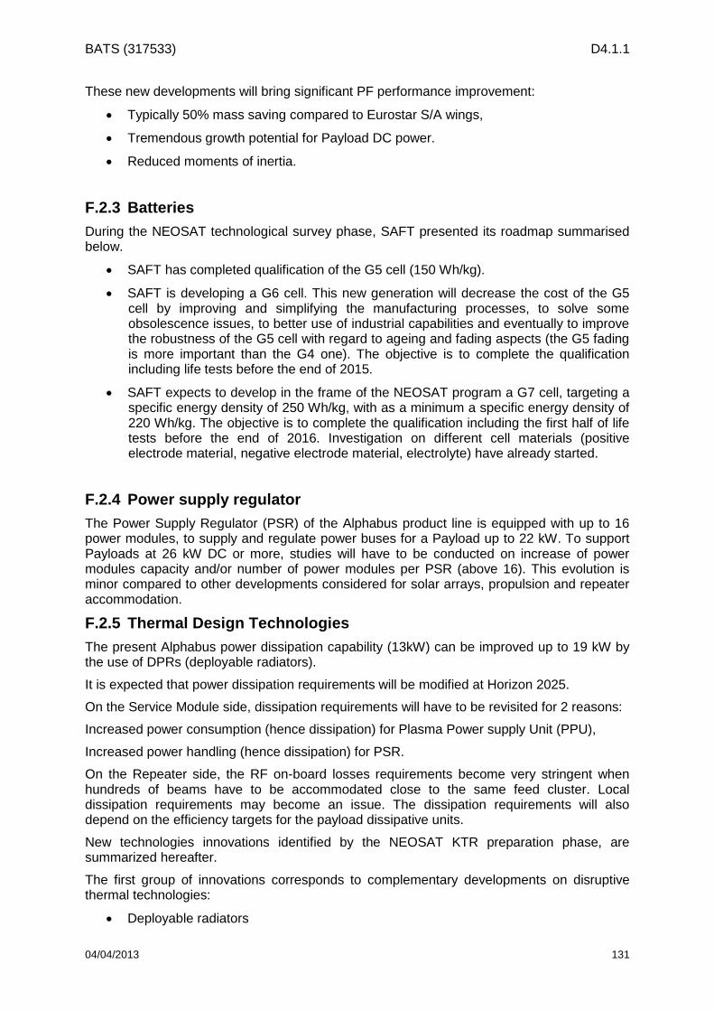
BATS (317533) D4.1.1
04/04/2013 131
These new developments will bring significant PF performance improvement:
Typically 50% mass saving compared to Eurostar S/A wings,
Tremendous growth potential for Payload DC power.
Reduced moments of inertia.
F.2.3 Batteries
During the NEOSAT technological survey phase, SAFT presented its roadmap summarised below.
SAFT has completed qualification of the G5 cell (150 Wh/kg).
SAFT is developing a G6 cell. This new generation will decrease the cost of the G5 cell by improving and simplifying the manufacturing processes, to solve some obsolescence issues, to better use of industrial capabilities and eventually to improve the robustness of the G5 cell with regard to ageing and fading aspects (the G5 fading is more important than the G4 one). The objective is to complete the qualification including life tests before the end of 2015.
SAFT expects to develop in the frame of the NEOSAT program a G7 cell, targeting a specific energy density of 250 Wh/kg, with as a minimum a specific energy density of 220 Wh/kg. The objective is to complete the qualification including the first half of life tests before the end of 2016. Investigation on different cell materials (positive electrode material, negative electrode material, electrolyte) have already started.
F.2.4 Power supply regulator
The Power Supply Regulator (PSR) of the Alphabus product line is equipped with up to 16 power modules, to supply and regulate power buses for a Payload up to 22 kW. To support Payloads at 26 kW DC or more, studies will have to be conducted on increase of power modules capacity and/or number of power modules per PSR (above 16). This evolution is minor compared to other developments considered for solar arrays, propulsion and repeater accommodation.
F.2.5 Thermal Design Technologies
The present Alphabus power dissipation capability (13kW) can be improved up to 19 kW by the use of DPRs (deployable radiators).
It is expected that power dissipation requirements will be modified at Horizon 2025.
On the Service Module side, dissipation requirements will have to be revisited for 2 reasons:
Increased power consumption (hence dissipation) for Plasma Power supply Unit (PPU),
Increased power handling (hence dissipation) for PSR.
On the Repeater side, the RF on-board losses requirements become very stringent when hundreds of beams have to be accommodated close to the same feed cluster. Local dissipation requirements may become an issue. The dissipation requirements will also depend on the efficiency targets for the payload dissipative units.
New technologies innovations identified by the NEOSAT KTR preparation phase, are summarized hereafter.
The first group of innovations corresponds to complementary developments on disruptive thermal technologies:
Deployable radiators

BATS (317533) D4.1.1
04/04/2013 132
LHP (Loop Heat Pipe)
Thermal Buses (MPL / HPS)
Use of East West radiative faces.
The second group of innovations is dedicated to improvement of competitiveness and/or performances of thermal control:
phase structures
Self-regulating Heaters
New OSR products & OSR films
The third group of innovations is dedicated to reduce of the Platform Thermo-elastic distortions.
The fourth group corresponds to damping systems at secondary structure or spacecraft interface.
F.2.6 Electric propulsion technologies
The following technology developments are required for the electric propulsion sub-system, in order to cope with the requirements for the large satellite mission:
improved plasma thrusters impulse and thrust, qualified for extended hours operations,
improved Xenon tank capacity (from 700 kg presently up to eg 1 ton),
power supply unit compatible with above plasma thrusters.
Following criteria can be used to rank the engines technologies:
Dual operating mode capability (orbit raising and station keeping),
Performance of the technology within foreseen range and mission scenario (orbit raising of 2 months with high thrust, station keeping with high specific impulse),
Heritage and maturity.
Hall Effect Thrusters (HET) are promising: they have the necessary performance, operating flexibility and maturity to match expected needs.
The available thrust can be tuned, up to twice more than for ion gridded thrusters, thus reducing the transfer time by a factor of two.
The specific impulse can also be tuned to provide more performance on station that minimises the performance loss compared to ion gridded thrusters (from 1600s to 2700s, as opposed to 4000s).
All relevant thrusters will require the development and qualification of a new PPU or an upgrade of the PPU MkII, to provide adequate 5 kW power supply.
5 kW engines exist within Europe (eg PPS-5000, T6) and worlwide (eg SPT-140D, BPT-4000).

BATS (317533) D4.1.1
04/04/2013 133
Annex G - Regulatory Analysis
G.1 Introduction
The Radio Regulations of the ITU defines, in general terms, the management of the radio electric spectrum all over the world. However, some flexibility exists in the actual usage of the frequency bands at the regional and the national levels.
In Europe, at the regional level, the CEPT keeps the European Common Allocation (ECA) Table up to date with the long term goal of harmonizing the radio electric spectrum usage over the 46 member countries. Each country has at its disposal its own frequency allocation table managed by the National Regulatory Authority (NRA). Usually this table follows the Radio Regulations but can have, to a certain extent, some national specificity.
Within the framework of BATS project, a study of the regulatory situation of the Ka and Q/V frequency bands is necessary to assess the spectrum availability for the satellite system as well as a study of the operating conditions of the latter in the chosen geographical area. In particular, the study aims at identifying and estimating the possible associated risks, i.e. the risks concerning the authorization requests to obtain the rights, from the national regulatory authority, to set the main stations.
Note: Implementation level colour code of the European decisions:
G.2 Ka band
This section deals with the regulatory status of the Ka-band in accordance with the ITU regulations as well as the European regulation.
The Ka band is divided in three sub-bands: the shared civil Ka-band, the exclusive civil Ka-band and government Ka-band.
The sub-bands of interest in this study are the civil bands which are the frequency bands presented below:
Shared civil Ka-band:
o Downlink: 17.7-19.7 GHz.
o Uplink: 27.5-29.5 GHz.
Exclusive civil Ka-band (commercial band):
o Downlink: 19.7 – 20.2 GHz
o Uplink: 29.5 – 30 GHz.
The government Ka band includes an additional 1 GHz allocated to the Fixed-Satellite Service (FSS) in the downlink and in the uplink (respectively 20.2 to 21.2 GHz and 30.0 to 31.0 GHz). Moreover, this band is subject to specific agreements and particular operating conditions which are, among other things, decided within the NATO and within the armed forces headquarters. For these reasons, the government Ka-band won’t be taken into account in the analysis
G.2.1 Status at the ITU level
From the point of view of frequency band allocations, the world is divided into three Regions as shown on the map below. The mainland of France is located in Region 1, it is to be noted that the French overseas territories are located in Region 2 and Region 3.
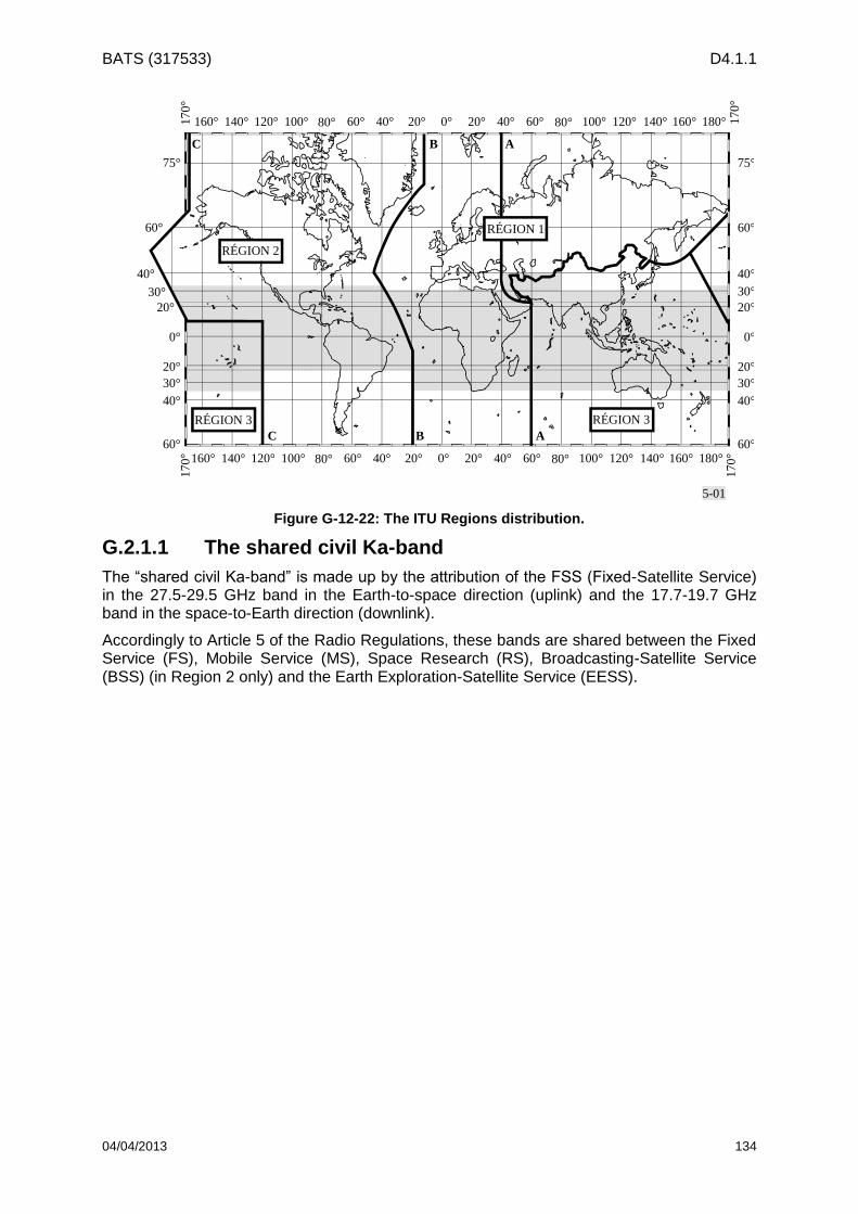
BATS (317533) D4.1.1
04/04/2013 134
5-01
75°
60°
40°
30°
20°
0°
20°
30°
40°
60°
75°
60°
40°
30°
20°
0°
20°
30°
40°
60°
170° 140°160° 100°120° 60°80° 20°40° 0° 20° 40° 60° 80° 100° 120° 140° 160° 180°
170°
170°
140°160° 100°120° 60°80° 20°40° 0° 20° 40° 60° 80° 100° 120° 140° 160° 180° 170°
ABC
ABC
RÉGION 1
RÉGION 2
RÉGION 3 RÉGION 3
Figure G-12-22: The ITU Regions distribution.
G.2.1.1 The shared civil Ka-band
The “shared civil Ka-band” is made up by the attribution of the FSS (Fixed-Satellite Service) in the 27.5-29.5 GHz band in the Earth-to-space direction (uplink) and the 17.7-19.7 GHz band in the space-to-Earth direction (downlink).
Accordingly to Article 5 of the Radio Regulations, these bands are shared between the Fixed Service (FS), Mobile Service (MS), Space Research (RS), Broadcasting-Satellite Service (BSS) (in Region 2 only) and the Earth Exploration-Satellite Service (EESS).

BATS (317533) D4.1.1
04/04/2013 135
Table G-12-6: Allocation to services in the 17.7-19.7 GHz band according to the ITU.
Allocation to services
Region 1 Region 2 Region 3
17,7-18,1
FIXED
FIXED-SATELLITE
(space-to-Earth)
(Earth-to-space)
MOBILE
17,7-17,8
FIXED
FIXED-SATELLITE
(space-to-Earth)
(Earth-to-space)
BROADCASTING-SATELLITE
Mobile
17,7-18,1
FIXED
FIXED-SATELLITE
(space-to-Earth)
(Earth-to-space)
MOBILE
17,8-18,1
FIXED
FIXED-SATELLITE
(space-to-Earth)
(Earth-to-space)
MOBILE
18,1-18,4 FIXED
FIXED-SATELLITE (space-to-Earth) (Earth-to-space)
MOBILE
18,4-18,6 FIXED
FIXED-SATELLITE (space-to-Earth)
MOBILE
18,6-18,8
EARTH EXPLORATION-
SATELLITE (passive)
FIXED
FIXED-SATELLITE
(space-to-Earth)
MOBILE except aeronautical
mobile
Space Research (passive)
18,6-18,8
EARTH EXPLORATION-
SATELLITE (passive)
FIXED
FIXED-SATELLITE
(space-to-Earth)
MOBILE except aeronautical
mobile
SPACE RESEARCH (passive)
18,6-18,8
EARTH EXPLORATION-
SATELLITE (passive)
FIXED
FIXED-SATELLITE
(space-to-Earth)
MOBILE except aeronautical
mobile
Space Research (passive)
18,8-19,3 FIXED
FIXED-SATELLITE (space-to-Earth)
MOBILE
19,3-19,7 FIXED
FIXED-SATELLITE (space-to-Earth)
MOBILE
Table G-12-7: Allocation to services in the 27.5-29.5 GHz band according to the ITU.
Allocation to services
Region 1 Region 2 Region 3
27,5-28,5 FIXED
FIXED-SATELLITE (Earth-to-space)
MOBILE
28,5-29,1 FIXED
FIXED-SATELLITE (Earth-to-space)
MOBILE
Earth Exploration-satellite (Earth-to-space)
29,1-29,5 FIXED
FIXED-SATELLITE (Earth-to-space)
MOBILE
Earth Exploration-satellite (Earth-to-space)

BATS (317533) D4.1.1
04/04/2013 136
Article 21 of the Radio Regulations defines the power flux-density limits at the Earth’s surface produced by emission of a space station, enabling the sharing between services having equal rights in a given frequency band. These limits of power flux-density are obtained under assumed free-space propagation conditions.
Table G-12-8: Power flux-density limits in the shared Ka-band.
Frequency band Service
Limit in dB (W/m2) for angles of arrival (δ)
above the horizontal plane Reference
bandwidth 0-5 5-25
25-
90
17.7-19.7 GHz Fixed-satellite
(Space-to-Earth) –115 –115 + 0.5 ( – 5) –105 1 MHz
-116
-114
-112
-110
-108
-106
-104
0 10 20 30 40 50 60 70 80 90
angle d'incidence (°)
Pu
iss
an
ce
su
rfa
ciq
ue
(d
BW
/m²
da
ns
1
MH
z)
Figure G-12-23: Power flux-density limits in the shared Ka-band.
The equivalent isotropically radiated power (e.i.r.p.) limits to be respected by the terrestrial services are defined by Article 21.3 of the Radio Regulations. The equivalent isotropically radiated power of a station of the Fixed or Mobile Service must not exceed +55 dBW (absolute EIRP., no association is given with a reference bandwidth).
For frequency bands above 15 GHz (except 25.25-27.5 GHz), there is no restriction on the angular separation with respect to the geostationary-satellite orbit for transmitting stations of the Fixed or Mobile Service (more precisely, the direction from the centre of radiation of any antenna type).
Article 22.2 of the Radio Regulations stipulates that the geostationary satellites (GSO) have priority on the non-geostationary satellites (nGSO) unless otherwise specified in the Regulations. However, in accordance with the footnotes Nos 5.523A and 5.523B of Article 5 of the Radio Regulations, this Article 22.2 does not apply to the frequency bands 18.8-19.6 GHz and 28.6-29.4 GHz. In these bands, the geostationary and non-geostationary networks have equal rights from a coordination point of view. This means that every new satellite system wishing to use these bands will have to coordinate itself with the GSO and nGSO satellite systems which have submitted their filings prior to the new network. These bands
Angle of arrival (°)
Po
we
r fl
ux d
en
sit
y (d
BW
/m²
in 1
MH
z)

BATS (317533) D4.1.1
04/04/2013 137
were destined to non-geostationary systems such as TELEDESIC at the time of the WRC-95 and to feeder links of MSS systems such as IRIDIUM. These “TELEDESIC” bands have also been identified during WRC-03 as being part of the HDFSS bands (high density application of the Fixed-Satellite Service). In 2003, TELEDESIC informs the ITU of their request to cancel all of their non-geostationary filings in these bands (LEOSTAR) and to return their Ka-band license.
G.2.1.2 The exclusive Ka-band
The “exclusive civil Ka-band” is not shared with the terrestrial services and is made up by the 29.5-30.0 GHz band for Earth-to-space communications (uplink) and by the 19.7-20.2 GHz band for space-to-Earth communications (downlink). The 2x500 MHz have been allocated to the Fixed-Satellite Service on a primary basis and they constitute a frequency core that operators wishing to implement a satellite service in Ka-band already use and will continue to use. Due to their exclusivity to the space services, these bands offer favourable conditions for satellite systems business – called “broadband” – with terrestrial uncoordinated stations (i.e. user terminals)
G.2.2 Status at CEPT level
G.2.2.1 The shared civil Ka-band
In Europe, the space services and terrestrial services are implemented in distinct parts of the spectrum in order to establish a favourable regulatory background for the “broadband” satellite applications.
The segmentation of the shared civil Ka-band in Europe is established by the ERC and ECC’s Decisions
The operating conditions applying to the downlinks of the shared civil Ka-band are set up by the Decision ERC/(00)/07 entitled “On the shared use of the band 17.7 – 19.7 GHz by the Fixed Service and Earth stations of the Fixed-Satellite Service (space-to-earth)”. This decision sets the conditions for which the 17.7-19.7 GHz band is shared between uncoordinated/unprotected earth stations (i.e. user terminals), coordinated earth stations (i.e. gateways) and terrestrial stations.
The earth stations of the Fixed-Satellite Service (space-to-Earth) which are not coordinated (user terminals) through the application of a national frequency assignment process, shall not claim protection from the stations of the Fixed Service.
In practice, this means that the uncoordinated earth stations of the Fixed-Satellite Service are on a secondary basis towards the station of the Fixed Service in the 17.7-19.7 GHz band.
However, in order to decrease the probability of interference to the uncoordinated earth stations, the Fixed Service shall, to the extent possible, implement mitigation techniques such as automatic transmitter power control, use of high performance antenna (low side lobes) and EIRP. emissions limited to the minimum necessary to fulfil the performance objectives in the fixed link.
Furthermore, in order to avoid the interferences from the Fixed Service stations, uncoordinated earth stations in the Fixed-Satellite Service shall implement, when practical, mitigation techniques such as Dynamic Channel Assignment (dynamic selection by the Fixed-Satellite Service system of the non-interfered channels when available), use of high performance antenna (low side lobes) and site shielding.
The sharing of the 27.5-29.5 GHz bands in the uplink direction is set up by Decision ECC/DEC/(05)01 entitled “On the use of the 27.5 – 29.5 GHz by Fixed Services and uncoordinated earth stations of the Fixed-Satellite Service (Earth-to-space)”. This decision sets the conditions for which specific segments of the 27.5-29.5 GHz spectrum are for use by uncoordinated earth stations (user terminals for example) whereas other parts of the 27.5-29.5 GHz spectrum are for use by terrestrial links of the Fixed Service.

BATS (317533) D4.1.1
04/04/2013 138
In accordance to this Decision:
The bands 27.5-27.8285 GHz (328.5 MHz), 28.4445-28.8365 GHz (392 MHz) and 29.4525-29.5 GHz (47.5 MHz) are dedicated to the use of uncoordinated earth stations operating in the Fixed-Satellite Service and,
The bands 27.8285-28.4445 GHz (616 MHz) and 28.9485-29.4525 GHz (504 MHz) are dedicated to the use of Fixed Service systems.
In addition, the band 28.8365-28.9485 GHz (112 MHz) is also designated for the use of uncoordinated Fixed-Satellite Service earth stations, without prejudice to the Fixed Service systems licensed in this band in some countries prior to Mars 2005.
At the European level, there is no exemption from individual licensing. The FM44 group of the CEPT is currently working on the opportunities for exemption from individual licensing, but the studies are not yet completed.
At the French level, the user terminals cannot be declared individually and are authorized by a decision in allotment mode (which is equivalent to a global license). This allotment allows the use of one or more frequencies, or even a frequency band with the technical characteristics of the terminals on a given geographical area (at the most France mainland, an overseas territory or the French territory).
The member administrations of the CEPT shall not authorise the deployment of uncoordinated Fixed-Satellite Service earth stations in the bands dedicated to the use of the Fixed Service systems. In order to ease the sharing between the Fixed-Satellite Service and the Fixed Service, the CEPT has established a number of criteria the Fixed-Satellite Service shall conform to:
For all uncoordinated Fixed-Satellite Service (FSS) earth stations operating in the bands 27.5-27.8285 GHz, 28.4445-28.8365 GHz, 29.4525-29.5 GHz and 28.8365-28.9485 GHz:
The off axis EIRP density (angles greater than 7° from the axis of the main beam) radiated in the adjacent bands used by the Fixed Service shall be limited to -35 dBW/MHz;
The elevation angle shall be greater than 10°;
The Fixed-Satellite Service systems using uncoordinated earth station in the bands 27.5-27.8285 GHz, 28.4445-28.8365 GHz, 29.4525-29.5 GHz and 28.8365-28.9485 GHz shall implement Automatic Power Control in the uncoordinated FSS earth stations and/or automatic on-board satellite gain control;
The uncoordinated Fixed-Satellite Service earth stations shall not have their occupied band edges closer than 10 MHz from the edges of the bands 27.8285-28.4445 GHz and 28.9485-29.4525 GHz dedicated to the Fixed Service;
The coordinated earth stations of the Fixed-Satellite Service (i.e. the gateways) have access to the whole 2 x 2 GHz.

BATS (317533) D4.1.1
04/04/2013 139
Figure G-12-24: Implementation of Decision ERC/DEC/(00)07

BATS (317533) D4.1.1
04/04/2013 140
Figure G-12-25: Implementation of Decision ECC/DEC/(05)01
G.2.2.2 The exclusive Ka-band
In Europe, in order to create a specific regulatory background necessary for “broadband” satellite applications, the CEPT has proposed an “exemption from individual licensing” to be implemented in the frequency bands of the exclusive civil Ka-band. The applicable ECC’s Decisions dealing with the “exemption from individual licensing” in the exclusive civil bands are:
The ECC’s Decision ECC/DEC/(06)/02 entitled "on exemption from individual Licensing of low EIRP satellite terminals operating within the frequency bands 19.7 – 20.2 GHz (space-to-Earth) and 29.5 – 30 GHz (Earth-to-space)” defines the conditions for exemption from individual licensing of satellite terminals with an EIRP lower than +34dBW.
The ECC’s Decision ECC/DEC/(06)/03 entitled "on exemption from individual Licensing of high EIRP satellite terminals operating within the frequency bands 19.7 – 20.2 GHz (space-to-Earth) and 29.5 – 30 GHz (Earth-to-space)” defines the conditions for exemption from individual licensing of satellite terminals with an EIRP greater than +34 dBW and not exceeding 60 dBW.
In other words, since the terminals with an EIRP lower than +60 dBW operating in the Fixed-Satellite Service exclusive band are lowly liable to cause harmful interferences to other services, it then seems appropriate to implement a licensing approach on a global basis (i.e. no individual licensing for terminals).

BATS (317533) D4.1.1
04/04/2013 141
Figure G-12-26: Implementation of Decision ECC/DEC/(06)02

BATS (317533) D4.1.1
04/04/2013 142
Figure G-12-27: Implementation of Decision ECC/DEC/(06)03
Moreover, the Decision ERC/DEC/(99)/26 entitled “on exemption from Individual Licensing of Receive Only Earth Stations” is also valid in the 17.7-20.2 GHz band but only for receiving stations.
G.2.3 Constraints due to Iridium and O3B Systems
In the downlink band 18.8-19.7 GHz and uplink band 28.6-29.5 GHz, the Radio Regulations grant, through the non-application of Article 22.2, the same priority to the geostationary and non-geostationary satellites systems. Consequently, both types of systems shall coordinate with each other on the basis “first come, first served”.
This Article states:
Non-geostationary-satellite systems shall not cause unacceptable interference to and, unless otherwise specified in these Regulations, shall not claim protection from geostationary-satellite networks in the fixed-satellite service and the broadcasting-satellite service operating in accordance with these Regulations. No. 5.43A does not apply in this case.
According to footnotes 5.523A of Article 5 of the Radio Regulations, the use of the bands 18.8-19.3 GHz (space-to-Earth) and 28.6-29.1 GHz (Earth-to-space) by geostationary and non-geostationary FSS networks is subject to coordination under Article 9.11A and Article 22.2 does not apply.
According to footnotes 5.523D of Article 5 of the Radio Regulations, the use of the band 19.3-19.7 GHz (space-to-Earth) by geostationary FSS systems and by feeder links for non-
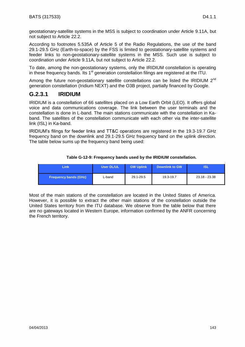
BATS (317533) D4.1.1
04/04/2013 143
geostationary-satellite systems in the MSS is subject to coordination under Article 9.11A, but not subject to Article 22.2.
According to footnotes 5.535A of Article 5 of the Radio Regulations, the use of the band 29.1-29.5 GHz (Earth-to-space) by the FSS is limited to geostationary-satellite systems and feeder links to non-geostationary-satellite systems in the MSS. Such use is subject to coordination under Article 9.11A, but not subject to Article 22.2.
To date, among the non-geostationary systems, only the IRIDIUM constellation is operating in these frequency bands. Its 1st generation constellation filings are registered at the ITU.
Among the future non-geostationary satellite constellations can be listed the IRIDIUM 2nd generation constellation (Iridium NEXT) and the O3B project, partially financed by Google.
G.2.3.1 IRIDIUM
IRIDIUM is a constellation of 66 satellites placed on a Low Earth Orbit (LEO). It offers global voice and data communications coverage. The link between the user terminals and the constellation is done in L-band. The main stations communicate with the constellation in Ka-band. The satellites of the constellation communicate with each other via the inter-satellite link (ISL) in Ka-band.
IRIDIUM’s filings for feeder links and TT&C operations are registered in the 19.3-19.7 GHz frequency band on the downlink and 29.1-29.5 GHz frequency band on the uplink direction. The table below sums up the frequency band being used:
Most of the main stations of the constellation are located in the United States of America. However, it is possible to extract the other main stations of the constellation outside the United States territory from the ITU database. We observe from the table below that there are no gateways located in Western Europe, information confirmed by the ANFR concerning the French territory.
Link
Frequency bands (GHz)
L-band 29.1-29.5 19.3-19.7 23.18 - 23.38
User DL/UL GW Uplink Downlink to GW ISL
Table G-12-9: Frequency bands used by the IRIDIUM constellation.

BATS (317533) D4.1.1
04/04/2013 144
Table G-12-10: List of IRIDIUM’s gateways declared outside of the United States of America.
Name Country Longitude Latitude Protection
IMEC GATEWAY JEDDAH Saudi Arabia 39°E 23’ 02’’ 21°N 23’ 49’’ Yes
GUARATIBA 1 Brazil 43°W 38’ 08’’ 22°S 59’ 56’’ No
GUARATIBA 2 Brazil 43°W 38’ 08’’ 22°S 59’ 56’’ No
PIRANEMA 1 Brazil 43°W 43’ 48’’ 22°S 50’ 47’’ No
PIRANEMA 2 Brazil 43°W 43’ 50’’ 22°S 50’ 46’’ No
IQALUIT 1 Canada 68°W 27’ 57’’ 63°N 44’ 27’’ Yes
IQALUIT 2 Canada 68°W 27’ 54’’ 63°N 44’ 27’’ Yes
IQALUIT 3 Canada 68°W 27’ 52’’ 63°N 44’ 26’’ Yes
IQALUIT 4 Canada 68°W 27’ 50’’ 63°N 44’ 25’’ Yes
YELLOWKNIFE 1 Canada 114°W 25’ 03’’ 62°N 25’ 07’’ Yes
YELLOWKNIFE 2 Canada 114°W 25’ 01’’ 62°N 25’ 07’’ Yes
YELLOWKNIFE 3 Canada 114°W 24’ 58’’ 62°N 25’ 06’’ Yes
YELLOWKNIFE 4 Canada 114°W 25’ 03’’ 62°N 25’ 05’’ Yes
ICELAND TTS1 Iceland 14°W 21’ 16’’ 65°N 20’ 40’’ No
ICELAND TTS2 Iceland 14°W 21’ 19’’ 65°N 20’ 40’’ No
NIC AZUMINO Japan 137°E 57’ 48’’ 36°N 18’ 38’’ Yes
NIC MIASA Japan 137°E 53’ 59’’ 36°N 33’ 52’’ Yes
CHINCHEON01 Korea 127°E 20’ 08’’ 36°N 55’ 53’’ Yes
CHINCHEON02 Korea 127°E 20’ 07’’ 36°N 55’ 52’’ Yes
CHUNGJU01 Korea 127°E 45’ 33’’ 37°N 08’ 04’’ Yes
CHUNGJU02 Korea 127°E 45’ 35’’ 37°N 08’ 03’’ Yes
KOROLEV/MAKROMIR Russia 37°E 47’ 34’’ 55°N 54’ 49’’ Yes
MOSCOW/MAKROMIR Russia 37°E 29’ 59’’ 55°N 45’ 28’’ Yes
In the absence of registered gateways in France, Benelux and Germany, the 1st generation constellation does not seem to pose any threat to future systems located in those countries. However the presence of two gateways near Moscow might create harmful interferences on systems located in Eastern Europe. Further studies shall be conducted to assess the threat level.
G.2.3.2 O3B
Only little public information is available concerning the O3B project. The two filings declared at the ITU via the British administration are fairly recent and both are in coordination process to date. The O3B-A network’s priority date is on the 18th April 2008 and its deadline is set on the 23rd October 2014. The O3B-B network’s priority date is on the 3rd February 2011 and its deadline is set on the 6th February 2016. The whole Ka-band in the space-to-Earth and Earth-to-space directions is declared.
The O3B project is officially announced to aim at the populations which have little or no Internet connection and at the developing countries. The links with the constellation are planned to be done only through the gateways. The information from this point is then routed to the users via the terrestrial networks. From this information, it can be assumed that the user terminals will be located outside of the area aimed by this study.
Concerning the gateways, if it happens that one or more of them shall be located in Europe, it’s then the priority date which will set the coordination order in the local interference area located around the considered gateway(s).

BATS (317533) D4.1.1
04/04/2013 145
G.2.4 Identification for HDFSS
According to the footnote 5.516B of Article 5 of the Radio Regulations, the CEPT decided through Decision ECC/DEC/(05)08 entitled “ on the availability of frequency bands for high density applications in the Fixed-Satellite Service (space-to-Earth and Earth-to-space) “, to assimilate the frequency bands 17.3-17.7 GHz, 19.7-20.2 GHz (space-to-Earth) and 29.5-30.0 GHz (Earth-to-space) to the use of high density applications subject to the market demand. However, this assimilation does not establish the priority or the usage exclusion among the users of the primary services assigned to these bands.
Although this assimilation concerns at once the exclusive satellite band and the 17.3-17.7 GHz band, many regulatory disparities remain as well as disparities in the use of these bands. This is due to the fact that the exclusive band has a clear exemption from individual licensing process via the Decisions ECC DEC (06)/02 and ECC DEC (06)/03 whereas the band 17.3-17.7 GHz does not have such a regulatory framework, which was presented in the preceding section.
G.2.5 Civil Ka-band Summary
Figure G-12-28 and Figure G-12-29 below explain entirely the segmentation of the civil Ka-band at the ECC level, as detailed in the preceding sections.
ECC Regulatory framework
Ka-band segmentation for uplink frequencies
47.5504 MHz112 500 MHz 1000 MHz328.5 MHz 616 MHz 392 MHz
Teledesic Band MSS feeder
28.6 29.529.1
27.5 3127.8285 3029.528.8365 28.9485 29.452528.4445
Legend:
Figure G-12-28: CEPT segmentation of the uplink bands from 27.5 to 31.0 GHz
ECC Regulatory framework
Ka-band segmentation for downlink frequencies
500 MHz 1000 MHz
19.6
MSS feederTeledesic Band
18.8 19.3
19.7 20.2 21.217.7 18.8 19.3
Legend:
Figure G-12-29: CEPT segmentation of the uplink bands from 17.7 to 21.2 GHz
FSS exclusive allocation. Gateways and uncoordinated terminals – ECC exemption from individual licensing
FSS/FS shared bands. No segmentation possible, application of mitigation techniques required
Governmental use in NATO countries
FSS exclusive allocation. Gateways and terminals – ECC exemption from individual licensing.
ECC designation for terrestrial services. Only coordinated FSS earth stations allowed
ECC exclusive designation for FSS – NO ECC exemption from individual licensing
ECC exclusive designation for FSS except in some CEPT countries
Governmental use in NATO countries
Coordinated FSS earth stations allowed in the whole shared band 27.5-29.5 GHz
2000 MHz
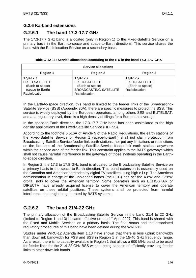
BATS (317533) D4.1.1
04/04/2013 146
G.2.6 Ka-band extensions
G.2.6.1 The band 17.3-17.7 GHz
The 17.3-17.7 GHz band is allocated (only in Region 1) to the Fixed-Satellite Service on a primary basis in the Earth-to-space and space-to-Earth directions. This service shares the band with the Radiolocation Service on a secondary basis.
Table G-12-11: Service allocations according to the ITU in the band 17.3-17.7 GHz.
Service allocations
Region 1 Region 2 Region 3
17,3-17,7
FIXED SATELLITE (Earth-to-space) (space-to-Earth)
Radiolocation
17,3-17,7
FIXED-SATELLITE (Earth-to-space)
BROADCASTING-SATELLITE
Radiolocation
17,3-17,7
FIXED-SATELLITE (Earth-to-space)
Radiolocation
In the Earth-to-space direction, this band is limited to the feeder links of the Broadcasting-Satellite Service (BSS) (Appendix 30A), there are specific measures to protect the BSS. This service is widely deployed by the European operators, among others SES and EUTELSAT, and at a regulatory level, there is a high density of filings for a European coverage.
In the space-to-Earth direction, the 17.3-17.7 GHz band has been assimilated to the high density applications of the Fixed-Satellite Service (HDFSS).
According to the footnote 5.516A of Article 5 of the Radio Regulations, the earth stations of the Fixed-Satellite Service of Region 1 (space-to-Earth) shall not claim protection from Broadcasting-Satellite Service feeder-link earth stations, nor put any limitations or restrictions on the locations of the Broadcasting-Satellite Service feeder-link earth stations anywhere within the service area of the feeder link. This constraint applies to the BATS gateways which shall not cause harmful interference to the gateways of those systems operating in the Earth-to-space direction.
In Region 2, the 17.3 to 17.8 GHz band is allocated to the Broadcasting-Satellite Service on a primary basis in the space-to-Earth direction. This band extension is essentially used on the Canadian and American territories by digital TV satellites using high e.i.r.p. The American administration in charge of the unplanned bands (the FCC) has set the 43°W and 179°W orbital slots to cover the American territory. Some operators such as ECHOSTAR or DIRECTV have already acquired license to cover the American territory and operate satellites on these orbital positions. These systems shall be protected from harmful interference that might be generated by BATS systems.
G.2.6.2 The band 21/4-22 GHz
The primary allocation of the Broadcasting-Satellite Service in the band 21.4 to 22 GHz (limited to Region 1 and 3) became effective on the 1st April 2007. This band is shared with the Fixed and Mobile Services on a primary basis. The final status and the associated regulatory procedures of this band have been defined during the WRC-12.
Studies under WRC-12 Agenda item 1.13 have shown that there is less uplink bandwidth than downlink bandwidth for FSS and BSS in Region 1 in the 15-40 GHz frequency range. As a result, there is no capacity available in Region 1 that allows a 600 MHz band to be used for feeder links for the 21.4-22 GHz BSS without being capable of efficiently providing feeder links to other downlink bands.

BATS (317533) D4.1.1
04/04/2013 147
The mismatch between the uplink and downlink capacity as observed in this case has been resolved by allocating two new frequency bands to the Fixed-Satellite Service:
including Region 1 in the 24.75-25.25 GHz FSS (Earth-to-space) allocation; and
an expansion by 100 MHz in the 24.65-24.75 GHz FSS (Earth-to-space) allocation.
Table G-12-12: Service allocations according to the ITU in the band 24.65-25.25 GHz.
Service allocations
Region 1 Region 2 Region 3
24,65-24,75
FIXED
FIXED SATELLITE (Earth-to-space)
INTER-SATTELITE
24,65-24,75
INTER-SATTELITE (Earth-to-space)
RADIOLOCATION-SATELLITE
(Earth-to-space)
24,65-24,75
FIXED
FIXED-SATELLITE (Earth-to-space)
INTER-SATTELITE
Mobile
24,75-25,25
FIXED
FIXED SATELLITE (Earth-to-space)
24,75-25,25
FIXED SATELLITE (Earth-to-space)
24,75-25,25
FIXED
FIXED SATELLITE (Earth-to-space)
MOBILE
Figure G-12-30: FSS/BSS pairing in Ka band.
The power flux-density at the Earth surface produced by emission of a Broadcasting-Satellite Service space station shall not exceed the limits defined in Table 21-4 of Article 21 of the Radio Regulations. These limits relates to the power flux-density which would be obtained under assumed free-space propagation conditions
Table G-12-13: Power-flux density limits in the 21.4-22 GHz band from Table 21-4 of Article 21.
Frequency band
Service
Limit in dB (W/m2) for angles
Reference bandwidt
h - - -
21.4-22 GHz
(Regions 1 et 3) Broadcasting-satellite –115 –115 + 0.5 ( – 5) –105 1 MHz
17,3 17,7
24,65
24,75
25,25 27,5 28,6 29,1 29,5 30,0
21,4 22,0 18,8 19,3 19,7 20,2
BSS
s-E
E-s

BATS (317533) D4.1.1
04/04/2013 148
-116
-114
-112
-110
-108
-106
-104
0 10 20 30 40 50 60 70 80 90
angle d'incidence (°)
Pu
iss
an
ce
su
rfa
ciq
ue
(d
BW
/m²
da
ns
1
MH
z)
Figure G-12-31: power flux-density limits in the 21.4-22.0 GHz band.
The Table 5-1 of Appendix 5 of the Radio Regulations sets the conditions for which coordination is to be effected or agreement sought with other administrations under the provision of Article 9 of the Radio Regulations.

BATS (317533) D4.1.1
04/04/2013 149
Table G-12-14: Technical conditions for coordination from Table 5-1 of Appendix 5.
Reference to
Article 9 Case
Frequency bands (and Region) of the service for which
the coordination is sought
Threshold/condition
Calculation method
Remarks
No. 9.7
GSO/GSO
(continued)
A station in a satellite network using the geostationary-satellite orbit (GSO), in any space radiocommunication service, in a frequency band and in a Region where this service is not subject to a Plan, in respect of any other satellite network using that orbit, in any space radiocommunication service in a frequency band and in a Region where this service is not subject to a Plan, with the exception of the coordination between earth stations operating in the opposite direction of transmission
6bis) 21.4-22GHz (Regions 1 et 3)
i) Bandwidth overlap; and ii) any network in the BSS and any associated space operation functions (see No. 1.23) with a space station within an orbital arc of ±12° of the nominal orbital position of a proposed network in the BSS
No. 9.41
does not
apply
In order to ease the coordination process of the new networks in the 21.4-22.0 GHz band, the WRC-12 decided that the coordination of assignments for Broadcasting-Satellite Service systems with respects to other Broadcasting satellite networks in the 21.4-22.0 GHz frequency band in Regions 1 and 3 is not required if the power flux-density produced under assumed free-space propagation conditions does not exceed the threshold values below:
–149.88 dB(W/(m2 · MHz)) for 0˚ ≤ θ < 0.6˚
–153.2 + 9.3 · θ² dB(W/(m2 · MHz)) for 0.6˚ ≤ θ < 1.05°
–143.5 + 27.2 · log θ dB(W/(m2 · MHz)) for 0.6˚ ≤ θ < 2.65°
–141.1 + 1.3 · θ² dB(W/(m2 · MHz)) for 2.65˚ ≤ θ < 4.35°
–133.2 + 26.1 · log θ dB(W/(m2 · MHz)) for 4.35˚ ≤ θ < 12°
–105 dB(W/(m2 · MHz)) for 12˚ ≤ θ
θ is the minimum nominal geocentric orbital separation, in degrees, between
the wanted and interfering space stations.

BATS (317533) D4.1.1
04/04/2013 150
Figure G-12-32: power flux-density limits in the 21.4-22.0 GHz band for coordination.
In order to ease development of the Broadcasting-Satellite Service in the 21.4-22.0 Ghz frequency band several measures are taken at the ITU level.
According to the footnote 5.D113 of Article 5 of the Radio Regulations, in the 21.4-22.0 GHz frequency band, unless otherwise agreed between the administrations concerned, any station in the Fixed or Mobile Services of an administration shall not produce a power flux-density in excess of −120.4 dB(W/(m2 · MHz)) at 3 m above the ground of any point of the territory of any other administration in Regions 1 and 3 for more than 20% of the time.
According to the footnote 5.B113 of Article 5 of the Radio Regulations In the band 21.4-22 GHz, in order to facilitate the development of the Broadcasting-Satellite Service, administrations in Regions 1 and 3 are encouraged not to deploy stations in the Mobile Service and are encouraged to limit the deployment of stations in the Fixed Service to point-to-point links.
The Special Procedure
Considering that the concept of “first come, first served” can restrict and in some case prevent the access to and use of certain frequency bands and orbit position, and considering further the relative disadvantages for developing countries in coordination negotiations, the WRC-12 decided to implement a special procedure in order to permit a more equitable access to the spectral and orbital resources in the 21.4-22.0 GHz frequency band for all administrations.
The special procedure can only be applied once by an administration or an administration acting on behalf of a group of named administrations when none of those administrations have a network in the Master International Frequency Register, notified under Article 11 or successfully examined under No. 9.34 and published under No. 9.38 for the band 21.4-22 GHz. If an administration has already made a submission under this special procedure, either individually or as a part of a group, if shall not benefit from this special procedure for a new submission.
Technical parameters to be used for Regions 1 and 3 for Broadcasting-Satellite Service networks under this special procedure are shown in the table below:

BATS (317533) D4.1.1
04/04/2013 151
Technical parameters Range Remarks
Antenna diameter of the receiving
earth station
45-120 cm Radiation pattern see
Recommendation ITU-R BO.1900
Noise temperature of the receiving
earth station
145-200 K
e.i.r.p. of the receiving earth station 43.2-58.2 dBW/MHz
Coverage National borders &
minimal coverage
ellipse generated by the
Bureau
Maximum of 20 points with
associated geographical
coordinates
Maximum pointing error of the
receiving earth station
0.1° In all directions
Maximum rotating error of the
receiving earth station
± 1°
Reference pattern of the receiving
earth station
See figure below
dBiGmax 0201log1045.44
Curve A : dB relative to main beam gain
2
0/12 5.0/0 0 for
2
0min
0
/
/12
B
x x
Bfor
0
min0
45.1/5.0
23.25 45.1/45.1
0
0
min
xB
for
Relative angle (φ/ φ0)
Rel
ati
ve
an
ten
na g
ain
( d
B )

BATS (317533) D4.1.1
04/04/2013 152
0/log2022 45.1/ 0 for
After intersection with curve B:
Curve B : Minus the on-axis gain (Curve B represents examples of four antennas having different
values of φ0 as labelled in the Figure above. The on-axis gains of these antennas are
approximately 39.9, 42.9, 45.9 and 48.9 dBi, respectively) Where :
: off axis angle (°)
:0 coss-sectional half power beamwidth in the direction of interest (°)
:, 0201 major and minor axis half power beamwidth, respectively, of elliptical beam.
0
min15.0
Bx 6.0minBwhere
Under the special procedure, the technical criteria which permit to avoid the coordination process in the band 21.4-22.0 GHz are presented below. Two cases are possible according to the characteristics of the filing towards which the coordination is sought.
In the case of a frequency assignation subject to the special procedure with regards to frequency assignments not subject to the special procedure and for which the notification is not submitted under Article 11 and the complete information requested for the application of this special procedure is not received by the Bureau, the following mask shall be applied:
–146.88 dB(W/(m2 · MHz)) avec 0˚ ≤ θ < 0.6˚
–150.2 + 9.3 · θ² dB(W/(m2 · MHz)) avec 0.6˚ ≤ θ < 1.05°
–140.5 + 27.2 · log θ dB(W/(m2 · MHz)) avec 0.6˚ ≤ θ < 2.65°
–138.1 + 1.3 · θ² dB(W/(m2 · MHz)) avec 2.65˚ ≤ θ < 4.35°
–130.2 + 26.1 · log θ dB(W/(m2 · MHz)) avec 4.35˚ ≤ θ < 9.1°
–105 dB(W/(m2 · MHz)) avec 9.1˚ ≤ θ
θ is the minimum nominal geocentric orbital separation, in degrees, between
the wanted and interfering space stations.
In the case of a frequency assignation subject to the special procedure with regards to frequency assignments subject and not subject to the special procedure and for which the notification is submitted under Article 11 or the complete information requested for the application of this special procedure is received by the Bureau, the following mask shall be applied:
–149.88 dB(W/(m2 · MHz)) avec 0˚ ≤ θ < 0.6˚
–153.2 + 9.3 · θ² dB(W/(m2 · MHz)) avec 0.6˚ ≤ θ < 1.05°
–143.5 + 27.2 · log θ dB(W/(m2 · MHz)) avec 0.6˚ ≤ θ < 2.65°
–141.1 + 1.3 · θ² dB(W/(m2 · MHz)) avec 2.65˚ ≤ θ < 4.35°
–133.2 + 26.1 · log θ dB(W/(m2 · MHz)) avec 4.35˚ ≤ θ < 12°
–105 dB(W/(m2 · MHz)) avec 12˚ ≤ θ

BATS (317533) D4.1.1
04/04/2013 153
θ is the minimum nominal geocentric orbital separation, in degrees, between
the wanted and interfering space stations.
At the European level, the 21.4-22 GHz is exclusively allocated to the space services with no sharing with the terrestrial services. However, certain type of short range radars can be deployed in this band on an interim basis. As mentioned in the Decision ECC/DEC/(04)/10, short range radar systems can be authorized on the European market but only during a limited period of time (until the 1st July 2013). Although the 21.4-22.0 GHz band is allocated to the Broadcasting-Satellite Service, there are some possibilities to operate a Fixed-Satellite Service system under a Broadcasting-Satellite Service allocation in this frequency band.
G.3 Q/V band
The Fixed-Satellite Service Q/V band is composed of 5 GHz for each direction, the uplink and the downlink. The downlink bands are contiguous contrary to the uplink bands. The bands’ segmentation is shown below:
uplink
o 42.5-43.5 GHz
o 47.2-50.2 GHz
o 50.4-51.4 GHz
downlink
o 37.5-42.5 GHz
Certain sub-parts of the uplink bands are also allocated to the Fixed-Satellite Service in the space-to-Earth direction (see next section) in Region 1, namely: 47.5-47.9 GHz, 48.2-48.54 GHz and 49.44-50.2 GHz.
In the framework of his prospection work, NATO has found in the “NATO Joint Frequency Agreement” the Q/V band proper to the development of future military systems in the Fixed-Satellite Service and Mobile-Satellite Service. The harmonized NATO bands are consequently the band 39.5 to 40 GHz on the downlink and its associated band 50.4 to 51.4 GHz on the uplink.
Unlike the government Ka-band which is assimilated to military uses in Europe, the 39.5-40 GHz band and its associated band could be shared between military and civil applications.
G.3.1 Status at the ITU level
G.3.1.1 Articles of the Radio Regulations
Article 5 of the Radio Regulations allocates the whole Q/V band to the Fixed-Satellite Service (FSS). This allocation is not exclusive. The band is mainly shared with the terrestrial services (Fixed, Mobile and Broadcasting Services) on a primary basis.
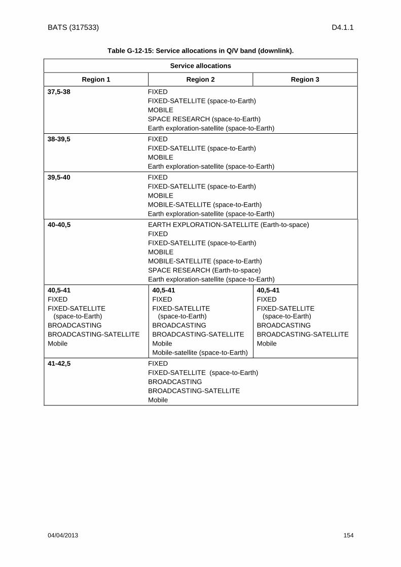
BATS (317533) D4.1.1
04/04/2013 154
Table G-12-15: Service allocations in Q/V band (downlink).
Service allocations
Region 1 Region 2 Region 3
37,5-38 FIXED
FIXED-SATELLITE (space-to-Earth)
MOBILE
SPACE RESEARCH (space-to-Earth)
Earth exploration-satellite (space-to-Earth)
38-39,5 FIXED
FIXED-SATELLITE (space-to-Earth)
MOBILE
Earth exploration-satellite (space-to-Earth)
39,5-40 FIXED
FIXED-SATELLITE (space-to-Earth)
MOBILE
MOBILE-SATELLITE (space-to-Earth)
Earth exploration-satellite (space-to-Earth)
40-40,5 EARTH EXPLORATION-SATELLITE (Earth-to-space)
FIXED
FIXED-SATELLITE (space-to-Earth)
MOBILE
MOBILE-SATELLITE (space-to-Earth)
SPACE RESEARCH (Earth-to-space)
Earth exploration-satellite (space-to-Earth)
40,5-41
FIXED
FIXED-SATELLITE (space-to-Earth)
BROADCASTING
BROADCASTING-SATELLITE
Mobile
40,5-41
FIXED
FIXED-SATELLITE (space-to-Earth)
BROADCASTING
BROADCASTING-SATELLITE
Mobile
Mobile-satellite (space-to-Earth)
40,5-41
FIXED
FIXED-SATELLITE (space-to-Earth)
BROADCASTING
BROADCASTING-SATELLITE
Mobile
41-42,5 FIXED
FIXED-SATELLITE (space-to-Earth)
BROADCASTING
BROADCASTING-SATELLITE
Mobile

BATS (317533) D4.1.1
04/04/2013 155
Table G-12-16: Service allocations in Q/V band (uplink).
Service allocations
Region 1 Region 2 Region 3
42,5-43,5 FIXED
FIXED-SATELLITE (Earth-to-space)
MOBILE except aeronautical mobile
RADIO ASTRONOMY
47,2-47,5 FIXED
FIXED-SATELLITE (Earth-to-space)
MOBILE
47,5-47,9
FIXED
FIXED-SATELLITE (Earth-to-space) (space-to-Earth)
MOBILE
47,5-47,9
FIXED
FIXED-SATELLITE (Earth-to-space)
MOBILE
47,9-48,2 FIXED
FIXED-SATELLITE (Earth-to-space)
MOBILE
48,2-48,54
FIXED
FIXED-SATELLITE (Earth-to-space) (space-to-Earth)
MOBILE
48,2-50,2
FIXED
FIXED-SATELLITE (Earth-to-space)
MOBILE
48,54-49,44
FIXED
FIXED-SATELLITE (Earth-to-space)
MOBILE
49,44-50,2
FIXED
FIXED-SATELLITE (Earth-to-space) (space-to-Earth)
MOBILE
50,4-51,4 FIXE
FIXED-SATELLITE (Earth-to-space)
MOBILE
Mobile-satellite (Earth-to-space)
According to the footnote 5.516B, the following bands are set for high density applications in the Fixed-Satellite Service (HDFSS):
39.5 to 40 GHz (space-to-Earth) in Region 1,
40 to 40.5 GHz (space-to-Earth) in all the Regions,
40.5 to 42 GHz (space-to-Earth) in Region 2,
47.5 to 47.9 GHz (space-to-Earth) in Region 1,

BATS (317533) D4.1.1
04/04/2013 156
48.2 to 48.54 GHz (space-to-Earth) in Region 1,
49.44 to 50.2 GHz (space-to-Earth) in Region 1, and
48.2 to 50.2 GHz (Earth-to-space) in Region 2.
This assimilation does not exclude the use of this band by other applications of the Fixed-Satellite Service (FSS) or by others services allocated to this band on a primary basis with equal rights. It does not establish priorities between the users of this band in the current Radio Regulations.
In addition, the 40.5-42.5 GHz band is also allocated to the Broadcasting-Satellite Service (BSS) on a primary basis.
G.3.1.2 Power flux-density limits applicable to the space services
In the case of shared frequency bands, the Radio Regulations has set either power flux-density limits, or coordination thresholds in order to assure a coexistence between the services. In the relevant frequency bands, the power flux-density limits are defined in Article 21 of the Radio Regulations.
Table G-12-17: Applicable power flux-density limits.
Frequency bands Service
Limit in dB (W/m2) for angle
of arrival () above horizontal plane Reference bandwidth
0°-5° 5°-25° 25°-90°
37,5-40 GHz Fixed-satellite –127 5°-20° 20°-25° –105 1 MHz
–127 + (4/3) ( – 5)
–107 + 0,4 ( – 20)
40-40,5 GHz Fixed-satellite –115 –115 + 0,5( – 5) –105 1 MHz
40,5-42 GHz Fixed-satellite Broadcasting-satellite
–120 5°-15° 15°-25° –105 1 MHz
–120 + ( – 5) –110 + 0,5 ( – 15)
42-42,5 GHz Fixed-satellite
Broadcasting-satellite
–127 5°-20° 20°-25° –105 1 MHz
In Region 1:
47.5-47.9 GHz
48.2-48.54 GHz
49.44-50.2 GHz
Fixed-satellite
–115 –115 + 0,5( – 5) –105 1 MHz

BATS (317533) D4.1.1
04/04/2013 157
Figure G-12-33: PFD limits in Q/V band.
Besides, the 42.5-43.5 GHz and the 48.94-49.04 GHz frequency bands are allocated to the Radio Astronomy Service on a primary basis. Further restrictions are applied to out-of-band power flux-density limits.
According to the footnote 5.551I of Article 5 of the Radio Regulations, The power flux-density in the band 42.5-43.5 GHz produced by any geostationary space station in the Fixed-Satellite Service (space-to-Earth), or the Broadcasting-Satellite Service operating in the 42-42.5 GHz band, shall not exceed the following values at the site of any radio astronomy station:
–137 dB(W/m2) in 1 GHz and –153 dB(W/m2) in any 500 kHz of the 42.5-43.5 GHz band at the site of any radio astronomy station registered as a single-dish telescope; and
–116 dB(W/m2) in any 500 kHz of the 42.5-43.5 GHz band at the site of any radio astronomy station registered as a very long baseline interferometry station.
The limits in this footnote may be exceeded at the site of a radio astronomy station of any country whose administration so agreed.
According to the footnote 5.555B of Article 5 of the Radio Regulations, The power flux-density in the band 48.94-49.04 GHz produced by any geostationary space station in the Fixed-Satellite Service (space-to-Earth) operating in the band 48.2-48.54 GHz and 49.44-50.2 GHz shall not exceed –151.8 dB(W/m2) in any 500 kHz band at the site of any radio astronomy station.
G.3.1.3 EIRP limits applicable for terrestrial services
According to Article 21.3 of the Radio Regulations, the maximum equivalent isotropically radiated power (EIRP) of a station in the Fixed or Mobile Service shall not exceed +55 dBW.
As far as practicable, sites for transmitting stations, in the Fixed or Mobile Service, should be selected so that the direction of maximum radiation of any antenna will be separated from the geostationary satellite orbit by a minimal angular separation taking into account the effect of atmospheric refraction. However in the case of frequency bands above 15 GHz (except 25.25-27.5 GHz), there is no restriction on the angular separation for transmitting stations of the Fixed or Mobile Service.
Angle of arrival (φ/ φ0)
PF
D l
imit
s in
dB
(W/m
²) i
n 1
MH
z
37.5-40 GHz & 42-42.5 GHz
40-40.5 & 47.5-47.9 GHz & 48.2-48.54 GHz & 49.44-50.2 GHz
40.5-42 GHz

BATS (317533) D4.1.1
04/04/2013 158
G.3.1.4 Protection of the Radio Astronomy Service
The Radio Astronomy Service shares a number of frequency bands with the Fixed-Satellite Service (FSS) on a primary basis. In this case, it is necessary to protect the already registered radio astronomy sites. Indeed, as far as practicable, administrations shall use all appropriate means to provide protection from harmful interference to the Radio Astronomy Service on a permanent or temporary basis. The Radio Astronomy Service is extremely susceptible to interference from space or airborne transmitters.
The Radio Astronomy Service is characterized by the exceptionally high sensitivity of its receivers, and the frequent need for long periods of observation without harmful interference. Considering the small number of radio astronomy stations in each country and their known location often make it practical to give special considerations to the avoidance of interference such as geographical separation, site shielding, antenna directivity, the use of time-sharing or minimal practical transmitter power.
The essential rules to follow concerning the Radio Astronomy Service protection can be found in Article 29 of the Radio Regulations. The harmful interference criteria are defined in the Recommendation ITU-R RA.769-2 which gathers the power flux-density thresholds above which the Radio Astronomy Service suffers harmful interferences.
The table below provides a non-exhaustive list of stations susceptible to be inferred:
Table G-12-18: List of stations operating in the Radio Astronomy Service.
Finland Metsahovi 60°N 15' 03" 24°E 23' 34'' 60 14
France Bordeaux 44°N 50' 00'' 0°E 32' 00'' 73 2.5
Germany Effelsberg 50°N 31' 01" 6°E 52' 58'' 369 100
Medicina 44°N 31' 15" 11°E 38' 49" 28 32
Noto 36°N 52' 33" 14°E 59' 20" 60 32
Sardinia RT 39°N 29' 49" 9°E 14' 38" 650 64
Fian Puschino 54°N 49' 58" 37°E 40' 01" 200 22
Ipfan Zimenky 56°N 08' 59" 43°E 57' 00" 200 15
Yebes Ra 50°N 31' 01" 4°W 54' 39" 931 40
Iram-IGN 37°N 03' 58'' 3 °W 23' 34'' 2850 30
Robledo MDSCC 40°N 25' 37" 5°W 45' 03" 761 64
Sweden Onsala Space Observatory 57°N 24' 00" 11°E 55' 58" 10 25
MERLIN Network
Cambridge 52°N 10' 00" 0°E 02' 00'' 24 32
Darnhall 53°N 09' 00'' 2°W 32' 00'' 47 25
Deffort 52°N 05' 00'' 2°W 08' 00'' 25 25
Jodrell Bank 53°N 14' 00'' 2°W 18' 00'' 78 76 , 38x25
Knockin 52°N 47' 00'' 3°W 00' 00'' 66 25
Pickmere 53°N 17' 00'' 2°W 27' 00'' 35 25
Ukraine Kao Simeiz 44°N 24' 00" 34°E 01' 01" 50 22
Telescope
m)
Altitude
(m)Station Name Latitude LongitudeCountry
United Kingdom
Italy
Russia
Spain
The following table shows the overlapping bands between BATS project and the Radio Astronomy Service.

BATS (317533) D4.1.1
04/04/2013 159
Table G-12-19: Frequency bands registered for radio astronomy stations operation.
Station Name Me
tsa
ho
vi
Bo
rde
au
x
Eff
els
be
rg
Me
dic
ina
No
to
Srt
Fia
n P
usch
ino
Ipfa
n Z
ime
nky
Ye
be
s R
a
Ira
m-I
GN
Ro
ble
do
MD
SC
C
On
sa
la S
pa
ce
Ob
s
Ca
mb
rid
ge
Da
rnh
all
De
ffo
rt
Jo
dre
ll B
an
k
Kn
ockin
Pic
km
ere
Ka
o S
ime
iz
Country FIN F D S UKR
42.50 - 43.50 GHz X x X X X X X X X x X X x x x x x x X
48.94 - 49.04 GHz x x X x X X
GI ERUS
X Protected at the ITU
x Declared at the ESF
x Planned at the ESF
The European Science Foundation (ESF) is an association regrouping 72 scientific organisations in 30 European countries. Its
goal is to promote scientific researches and to improve the European cooperation in this domain.
Figure G-12-34: Location of the radio astronomy stations referred in Table 14
G.3.1.5 Protection of the Earth-Exploration Service (Passive)
The 50.2-50.4 GHz band is allocated to several passive services, namely the Space Research (SR) and the Earth Exploration-Satellite Service (EESS). Considering that the unwanted radiations produced by active services can cause harmful interferences to passive services, and in order to ensure the correct functioning of systems operating in these services without any interference, all emissions are prohibited in this band.
Moreover, the Resolution 750 applies. The unwanted emissions from stations brought into use in the bands and services directly adjacent shall not exceed the corresponding limits included in the Table below, subject to the specified conditions. In this way, additional limits apply to the band 49.7-50.2 GHz.
Note that these limits apply under clear-sky conditions. During fading conditions, the limits may be exceeded by earth stations when using uplink power control.

BATS (317533) D4.1.1
04/04/2013 160
Table G-12-20: Power limits to respect in the 49.7-50.2 GHz band.
EESS (passive)
band
Active service band
Active service
Limit of unwanted emission power from active service stations in a specified bandwidth within the EESS
(passive) band
50.2-50.4
GHz
49.7-50.2
GHz
Fixed-satellite (Earth to-space)
For stations brought into use after the date of entry into force of the Final Acts of WRC-07:
10 dBW into the 200 MHz of the EESS (passive)
band for earth stations having an antenna gain
greater than or equal to 57 dBi
20 dBW into the 200 MHz of the EESS (passive)
band for earth stations having an antenna gain less
than 57 dBi
G.3.2 Status at the CEPT level
The ERC report 025 (European Allocation Table) sets the allocations for the downlink from 37.5 GHz to 42.5 GHz as in the Radio Regulations, namely, the sharing between terrestrial services and Fixed-Satellite Services (FSS) on a primary basis.
However, some additional measures apply at the European level. To be mentioned:
Decision ERC/DEC/(00)02 “on the use of the band 37.5 - 40.5 GHz by the Fixed Service and Earth stations of the Fixed-Satellite Service (space-to-Earth)”
Decision ECC/DEC/(02)04 “on the use of the band 40.5 – 42.5 GHz by terrestrial (Fixed Service/Broadcasting Service) systems and uncoordinated Earth stations in the Fixed-Satellite Service and Broadcasting-Satellite Service (space-to-Earth)”
Decision ECC/DEC/(05)08 “on the availability of frequency bands for high density applications in the Fixed-Satellite Service (space-to-Earth and Earth-to-space)”
Considering that the 39.5-40.5 GHz is not used by the Fixed Service (at European level), the Decision ERC/DEC/(00)02 decrees that the 39.5-40.5 GHz band is allocated to the use of coordinated and uncoordinated earth stations.
Considering further that the future expansion of the Fixed Service in the bands 37.5-39.5 GHz is of vital importance to provide Europe’s telecommunication infrastructure, particularly in relation to mobile infrastructure network, and that the future expansion of terrestrial services in the band 40.5-42.5 GHz is essential to provide broadband multimedia wireless access throughout CEPT countries, the CEPT decides that the uncoordinated earth stations (broadband terminals) operating in the Fixed-Satellite Service or the Broadcasting-Satellite Service shall not claim protection from stations of the Fixed and Broadcasting Services.
In addition, the 47.2-49.2 GHz band is set to the usage of the Broadcasting-Satellite Service feeder links which operate in the band 40.5-42.5 GHz in the space-to-Earth direction.
The European Decision ECC/DEC/(05)08 sets the assimilation to high density applications of the frequency bands 47.5-47.9 GHz (space-to-Earth), 48.2-48.54 GHz (space-to-Earth) and 49.44-50.2 GHz (space-to-Earth) in Region 1. However, the deployment of uncoordinated earth stations is prohibited in these bands.
Concerning the frequency band 50.4-51.4 GHz, NATO has found in the “NATO Joint Frequency Agreement” the Q/V band proper to the development of future military systems in the Fixed-Satellite Service (FSS) and Mobile-Satellite Service (MSS). The 50.4 to 51.4 GHz is then put forward for the possible sharing between civil and military applications.

BATS (317533) D4.1.1
04/04/2013 161
In addition to this European restriction it is necessary to consider the national restrictions on this frequency band
The protection of passive services (EESS) requires the application of Resolution 750. The unwanted emissions from stations brought into use in the bands and services directly adjacent to the band 50.2-50.4 GHz shall not exceed the corresponding limits included in the Table below, subject to the specified conditions. In this way, additional limits apply to the band 50.4-50.9 GHz.
Note that these limits apply under clear-sky conditions. During fading conditions, the limits may be exceeded by earth stations when using uplink power control.
Table G-12-21: Power limits to respect in the 50.4-50.9 GHz band.
EESS (passive)
band
Active service band
Active service
Limit of unwanted emission power from active service stations in a specified bandwidth within the EESS
(passive) band
50.2-50.4
GHz
50.4-50.9
GHz
Fixed-satellite (Earth to-space)
For stations brought into use after the date of entry into force of the Final Acts of WRC-07:
10 dBW into the 200 MHz of the EESS (passive)
band for earth stations having an antenna gain
greater than or equal to 57 dBi
20 dBW into the 200 MHz of the EESS (passive)
band for earth stations having an antenna gain less
than 57 dBi

BATS (317533) D4.1.1
04/04/2013 162
Figure G-12-35: Implementation of decision ERC/DEC/(00)02

BATS (317533) D4.1.1
04/04/2013 163
Figure G-12-36: Implementation of decision ECC/DEC/(02)04
The figures below show the sharing set by the ECC between the existing services in the Q/V
band for the uplink and downlink, as detailed in the above sections.
Figure G-12-37 : CEPT sharing of the Q/V band (uplink) from 42.5 to 51.4 GHz

BATS (317533) D4.1.1
04/04/2013 164
Figure G-12-38 : CEPT sharing of the Q/V band (downlink) from 37.5 to 42.5 GHz
G.3.3 Remarks
Although the bandwidth available for the Fixed-Satellite Service (FSS) in the Q/V band is substantial, the predominance of the terrestrial services in Europe and the associated necessary protections restrict the deployment of uncoordinated earth stations (user terminals) in most of the Q/V band. Note that the deployment of uncoordinated earth stations shall remain possible in the 39.5-40.5 GHz bands. However, the future use of these bands by military applications could hamper the development of commercial systems in these bands in the future.
It is necessary to note that the limitations on the deployment of uncoordinated earth stations apply to Europe as a region. But the national authorities have implemented their own rules and differences from one country to another have to be considered.
G.3.4 Conclusion
The regulatory framework presented in this study permits the most adequate choice of frequency plan for the BATS system.
The following table sums up the regulation by distinguishing two distinct cases:
On one hand, the user terminals whose protection might be guaranteed only in the exclusive satellite bands;
On the other hand the gateways for which a successful coordination guarantees an acquired protection.
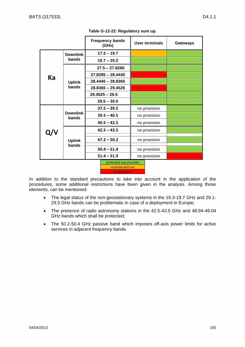
BATS (317533) D4.1.1
04/04/2013 165
Table G-12-22: Regulatory sum up.
Frequency bands (GHz)
User terminals Gateways
Ka
Downlink bands
17.3 – 19.7
19.7 – 20.2
Uplink bands
27.5 – 27.8285
27.8285 – 28.4445
28.4445 – 28.8365
28.8365 – 29.4525
29.4525 – 29.5
29.5 – 30.0
Q/V
Downlink bands
37.5 – 39.5 no provision
39.5 – 40.5 no provision
40.5 – 42.5 no provision
Uplink bands
42.5 – 43.5 no provision
47.2 – 50.2 no provision
50.4 – 51.4 no provision
51.4 – 51.9 no provision
protected use possible
unprotected use
no allocation
In addition to the standard precautions to take into account in the application of the procedures, some additional restrictions have been given in the analysis. Among those elements, can be mentioned:
The legal status of the non-geostationary systems in the 19.3-19.7 GHz and 29.1-29.5 GHz bands can be problematic in case of a deployment in Europe;
The presence of radio astronomy stations in the 42.5-43.5 GHz and 48.94-49.04 GHz bands which shall be protected;
The 50.2-50.4 GHz passive band which imposes off-axis power limits for active services in adjacent frequency bands.