D4.1: Description of Feasible Use Cases -...
52
Grant Agreement No.: 610764 Instrument: Collaborative Project Call Identifier: FP7-ICT-2013-10 PANACEA Proactive Autonomic Management of Cloud Resources D4.1: Description of Feasible Use Cases Version: v.1.0 Work package WP 4 Task Task 4.1 Due date 31/03/2013 Submission date Deliverable lead Eliezer Dekel (IBM) Version 1.0 Authors Dimiter Avresky, Eliezer Dekel, David Garcia Perez, Gokce Gorbil, Eduardo Huedo, Olivier Brun Reviewers Abstract In order to validate the capability to proactively manage cloud resources in a dynamic environment developed in PANACEA we will need to apply it to a particular scenario and show the improved availability and performance. In this document, we identify application scenarios for PANACEA, and analyze their feasibility as a validation vehicle for the scientific outputs of the project. These use cases will clearly demonstrate the
Transcript of D4.1: Description of Feasible Use Cases -...

Grant Agreement No.: 610764 Instrument: Collaborative Project Call Identifier: FP7-ICT-2013-10
PANACEA Proactive Autonomic Management of Cloud
Resources
D4.1: Description of Feasible Use Cases Version: v.1.0
Work package WP 4
Task Task 4.1
Due date 31/03/2013
Submission date
Deliverable lead Eliezer Dekel (IBM)
Version 1.0
Authors Dimiter Avresky, Eliezer Dekel, David Garcia Perez, Gokce Gorbil, Eduardo Huedo, Olivier Brun
Reviewers
Abstract In order to validate the capability to proactively manage cloud
resources in a dynamic environment developed in PANACEA we will need to apply it to a particular scenario and show the improved availability and performance. In this document, we identify application scenarios for PANACEA, and analyze their feasibility as a validation vehicle for the scientific outputs of the project. These use cases will clearly demonstrate the

D4.1: Description of Feasible Use Cases
© PANACEA Consortium 2014 Page 2 of 52
advantages of the technology developed by this project. The selection criteria include availability of data for training the machine learning algorithms, relevance, impact, and implementation feasibility. We present the use cases that we studied in order of preference for implementation. We will start with one use case and if time permits, we will move to the second one. Once we establish the results, they will also be used as part of the test bed activity and help validate the technology produced in the project. In addition, we discuss the ability to add proactive capabilities to Open Nebula.
Keywords Cloud, Proactive management, Machine Learning, Middleware, IaaS, PaaS, Hadoop, Mobile, Internet of Things

D4.1: Description of Feasible Use Cases
© PANACEA Consortium 2014 Page 3 of 52
Document Revision History
Version Date Description of change List of contributor(s)
V 0.5 03.03. 2014 Draft document for review Dimiter Avresky (Editor)
V 1.0 31.03.2014 Document after review Eliezer Dekel (Editor)
Disclaimer
The information, documentation and figures available in this deliverable, is written by the PANACEA Project– project consortium under EC grant agreement FP7-ICT-610764 and does not necessarily reflect the views of the European Commission. The European Commission is not liable for any use that may be made of the information contained herein.
Copyright notice
© 2013 - 2015 PANACEA Consortium
Project co-funded by the European Commission in the 7th Framework Programme (2007-2013)
Nature of the deliverable: R Dissemination Level
PU Public X PP Restricted to other programme participants (including the Commission Services) RE Restricted to bodies determined by the PANACEA project CO Confidential to PANACEA project and Commission Services

D4.1: Description of Feasible Use Cases
© PANACEA Consortium 2014 Page 4 of 52
EXECUTIVE SUMMARY
In order to validate the capability to proactively manage cloud resources in a dynamic environment developed in PANACEA we will need to apply it to a particular scenario and show the improved performance. In this document we identify application scenarios for PANACEA, and analyze their feasibility as a validation vehicle for the scientific outputs of the project. These use cases will clearly demonstrate the advantages of the technology developed by this project. The selection criteria include availability of data for training the machine learning algorithms, relevance, impact, and implementation feasibility. We present the use cases that we studied in order of preference for implementation. We will start with one use case and if time permits, we will move to the second one. Once we establish the results, they will also be used as a part of the test bed activity and help validate the technology produced in the project. In addition, we discuss in depth the ability to add proactive autonomic capabilities to Open Nebula.
We analyze features for proactive autonomic cloud computing at the virtual infrastructure level. The aim is to provide existing cloud providers with specifications about how to provide support for proactive autonomic systems on clouds. We consider several open source cloud technologies like Open Stack1, Cloud Stack2 etc. In this document we selected to cover OpenNebula as private/hybrid cloud manager, so we focus on features that are demanded by the OpenNebula3 community, as a horizontal use case to test and evaluate proactive and autonomic features PANACEA is bringing. For that, we analyze feature requests made by users through the OpenNebula development mailing list4.
A research and design principle would be that all these improvements could be easily implemented by popular cloud providers.
1 https://www.openstack.org/ 2 http://cloudstack.apache.org/ 3 http://opennebula.org/ 4 http://lists.opennebula.org/pipermail/dev-opennebula.org) or through the OpenNebula development portal (http://dev.opennebula.org/projects/opennebula/issues

D4.1: Description of Feasible Use Cases
© PANACEA Consortium 2014 Page 5 of 52
TABLE OF CONTENTS
EXECUTIVE SUMMARY .............................................................................................................. 4
TABLE OF CONTENTS ................................................................................................................ 5
LIST OF FIGURES ........................................................................................................................ 7
ABBREVIATIONS ........................................................................................................................ 8
1 INTRODUCTION ................................................................................................................. 10 1.1 Goals of this document .............................................................................................................................. 10 1.2 Organization of this document ............................................................................................................... 10
2 AUTONOMIC AND PROACTIVE COMPUTING ................................................................ 12
2.1 Properties of Proactive Autonomic Systems ...................................................................................... 12 2.2 Architecture for Autonomic Computing .............................................................................................. 13 2.3 ML Framework for a proactive autonomic management of cloud resources ....................... 14
3 APPLICATION SCENARIOS ............................................................................................... 16
3.1 First Use Case: cloud web hosting ......................................................................................................... 16 3.1.1 Cloud web hosting ...................................................................................................................... 16 3.1.2 Benefits expected from a proactive managed cloud .................................................................. 16 3.1.3 Relevance of this Use Case to PANACEA ................................................................................ 17 3.2 Second Use Case: Data Analytics as a service ................................................................................... 17 3.2.1 Data Analytics as a Service (DAaaS) ......................................................................................... 17 3.2.2 Benefits expected from a proactively managed cloud ............................................................... 22 3.2.3 Relevance of this Use Case to PANACEA ................................................................................ 23 3.3 Third Use Case: Internet of Things ......................................................................................................... 24
3.3.1 The COMPOSE project .............................................................................................................. 24 3.3.2 Benefits expected from a proactively managed cloud ............................................................... 28 3.3.3 Relevance of this Use Case to PANACEA ................................................................................ 28 3.4 Mobile telecommunications on the cloud .......................................................................................... 28 3.4.1 Mobile telecommunications on the cloud .................................................................................. 28 3.4.2 Benefits expected from a proactively managed cloud ............................................................... 30 3.4.3 Relevance of this Use Case to PANACEA ................................................................................ 30 3.5 Selection of use cases for experimentation ........................................................................................ 32
4 EXPERIMENTATION WITH SELECTED USE CASES .......................................................... 34

D4.1: Description of Feasible Use Cases
© PANACEA Consortium 2014 Page 6 of 52
4.1 Use case on cloud web hosting .............................................................................................................. 34
4.1.1 Experimentation with this use case ............................................................................................ 34 4.1.2 Experimental Setup .................................................................................................................... 35 4.2 Use case on Data Analytics as a Service .............................................................................................. 36 4.2.1 User configuring a new analysis of data (DAaaS-UC01) .......................................................... 36 4.2.2 Processing of the data following an specific workflow (DAaaS-UC02) ................................... 37 4.2.3 Review of the data by an user (DAaaS-UC03) .......................................................................... 38
5 OPENNEBULA AND PANACEA ......................................................................................... 39
5.1 Interesting OpenNebula Features for PROACTIVE Autonomic Systems ................................. 39 5.1.1 Architecture ................................................................................................................................ 39 5.1.2 Storage and Image Management ................................................................................................ 43 5.1.3 VM Management ....................................................................................................................... 44 5.1.4 Networking ................................................................................................................................. 47 5.1.5 Monitoring .................................................................................................................................. 48 5.1.6 Authentication and Authorization .............................................................................................. 49 5.2 Proposed Architecture and Features for OpenNebula to Support Proactive Autonomic Systems 49
6 CONCLUSIONS ................................................................................................................... 51
REFERENCES ............................................................................................................................. 52

D4.1: Description of Feasible Use Cases
© PANACEA Consortium 2014 Page 7 of 52
LIST OF FIGURES
Figure 1: IBM’s architecture for autonomic computing [1]. ....................................................... 13 Figure 2: Machine Learning Framework. ........................................................................................................ 14
Figure 3: Diagram of the DAaaS platform ..................................................................................................... 18
Figure 4: Functional block diagram of the DAaaS platform ................................................................... 18
Figure 5: Architecture and technologies used in the proposed solution. ......................................... 19
Figure 6: Block diagram of the solution ported to PANACEA ............................................................... 21
Figure 7: Possible deployment configuration .............................................................................................. 22
Figure 8: COMPOSE concept .............................................................................................................................. 25
Figure 9: The smart city Barcelona use case ................................................................................................. 26
Figure 10: Citizen services ................................................................................................................................... 26
Figure 11: COMPOSE architecture .................................................................................................................... 27
Figure 12: COMPOSE platform provider perspective ............................................................................... 27
Figure 13: Architecture of a UMTS (3G) mobile network ........................................................................ 30
Figure 14: Diagram of the Django/Apache server experimental setup. ............................................ 35
Figure 15: Infrastructure for OpenNebula ..................................................................................................... 40
Figure 16: OpenNebula architecture ............................................................................................................... 40
Figure 17: OpenNebula interfaces .................................................................................................................... 41
Figure 18: OpenNebula Sunstone .................................................................................................................... 42
Figure 19: Architecture for Autonomic Computing with OpenNebula. ............................................. 50

D4.1: Description of Feasible Use Cases
© PANACEA Consortium 2014 Page 8 of 52
ABBREVIATIONS
3G Third Generation
ACL Access Control List
ACM Autonomic Cloud Manager
API Application Programming Interface
AuC Authentication Center
CLI Command Line Interface
CN Core Network
DHCP Dynamic Host Configuration Protocol
DMTF Distributed Management Task Force
DNS Domain Name System
EIR Equipment Identity Register
GUI Graphical User Interface
HLR Home Location Register
HSS Home Subscriber Server
IP Internet Protocol
MNO Mobile Network Operator
ML Machine Learning
NAS Network Attached Storage
O&E Operations and Maintenance
OCA OpenNebula Cloud API
OCCI Open Cloud Computing Interface
OGF Open Grid Forum
OVF Open Virtualization Format
OVA Open Virtualization Appliance
QCOW QEMU Copy On Write
RAN Radio Access Network
REST REpresentational State Transfer
RNC Radio Network Controller
SAN Storage Area Network
SLA Service Level Agreement
VLAN Virtual Local Area Network

D4.1: Description of Feasible Use Cases
© PANACEA Consortium 2014 Page 9 of 52
UE User Equipment
UMTS Universal Mobile Telecommunications System
VM Virtual Machine
VMDK Virtual Machine DisK
W-CDMA Wideband Code Division Multiple Access
WP Work Package
XML-RPC eXtented Markup Language-Remote Procedure Call
D4.1: Description of Feasible Use Cases
© PANACEA Consortium 2014 Page 10 of 52
1 INTRODUCTION
1.1 Goals of this document
In order to validate the capability to proactively manage cloud resources in a dynamic environment developed in PANACEA we will need to apply it to a particular scenario and show the improved performance. In this document we present application scenarios for PANACEA, and analyze their feasibility as a validation vehicle for the scientific outputs of the project.
The proposed use cases serve two purposes. First, by gathering requirements from different application domains, they help us in defining the scope of the project and the technologies that will be developed. Second, some of the proposed use cases will be selected for experimentation. The selection criteria include availability of data for training the machine learning algorithms, relevance, impact, and implementation feasibility. The selected use cases will clearly demonstrate the advantages of the technology developed by this project.
We have produced two types of use cases:
• Four “vertical” use cases have been produced, each one pertaining to a particular application domain. We present the use cases that we studied in order of preference for implementation. The first two ones are those that we select for experimentation: the first use case deals with cloud web hosting while the second one is about Data Analytics as a Service. The two other use cases have the advantage of projecting ourselves in the future: the third one is in the fast developing area of sensors and mobile clouds and is directly related to the European IoT project COMPOSE, while the last one is devoted to mobile telecommunications on the cloud. For each of these application scenarios, we briefly describe the application domain, analyse the benefits that could be expected in this domain from proactively managed clouds, and discuss the relevance to PANACEA. We also provide a detailed description of how we are going to experiment with the two selected use cases.
• One “horizontal” use case was also obtained by polling the OpenNebula community in order to gather its requirements in terms of autonomic computing. The basic idea was to know what self-managing properties OpenNebula users are expecting, and to analyse how these properties can be implemented on top of existing OpenNebula resource management mechanisms. The primary goal of this use case is to guide the design of the PANACEA architecture.
Our plan is to start our experiments with the first use case as a first stage validation, and then move to the second one. Once we establish the results, they will also be used as a part of the test bed activity and help validate the technology produced in the project.
1.2 Organization of this document
The rest of this document is organized as follows:
• Chapter 2 gives some background on autonomic and proactive computing. It also provides a brief reminder of the main PANACEA objectives, with a particular emphasis
D4.1: Description of Feasible Use Cases
© PANACEA Consortium 2014 Page 11 of 52
on machine learning (ML) techniques.
• Chapter 3 describes the four proposed vertical use cases. We discuss the impact that the technologies developed in PANACEA could have in these application domains, and analyse the relevance of these use case to PANACEA. This chapter also presents the selection criteria that we have used to choose the use cases that we are going to experiment with.
• Chapter 4 describes in details how we are going to experiment with the selected application scenarios.
• Chapter 5 is devoted to the horizontal use case. We describe in details some of the existing resource management mechanisms of OpenNebula and show how they can be used for proactive and autonomic computing. A preliminary architecture is proposed.
• Chapter 6 draws some conclusions from this work.
D4.1: Description of Feasible Use Cases
© PANACEA Consortium 2014 Page 12 of 52
2 AUTONOMIC AND PROACTIVE COMPUTING
This chapter gives some background on autonomic and proactive computing. Section 2.1 presents the main properties of proactive autonomic system. Section 2.2 describes the architecture for autonomic computing defined by IBM. Finally, in Section 2.3, we remind the main objectives of PANACEA and briefly describe the ML techniques that will be used to achieve these objectives.
2.1 Properties of Proactive Autonomic Systems
Autonomic systems have the following properties [1]:
• Self-configuring: They have the ability to define themselves “on-the-fly”.
• Self-healing: They discover, diagnose, and react to disruptions.
• Self-optimizing (self-adapting): They can monitor and tune resources automatically.
• Self-protecting: They anticipate, detect, identify and protect themselves against threats from anywhere.
The following is a more complete list of features that should be exposed by any Cloud manager to deploy autonomic self-managing systems:
• Self-configuring features:
o systems can change configuration parameters (capacity, placement, connectivity...) at runtime
o systems can connect new devices at runtime (hot plugging)
• Self-healing features:
o systems can detect faults and recover from them
o systems can perform software rejuvenation
o systems can manage spares for application live migration
• Self-optimizing (self-adapting) features:
o systems can get information of the execution environment at runtime (self-awareness) and adapt to it (self-configuration)
o systems can manage elasticity
• Self-protecting features:
o systems can define and manage user access
o systems can detect attacks and recover from them
o systems can perform backup and recovery
On the other hand, proactivity or proactive behaviour refers to anticipatory, change-oriented and self-initiated behaviour, which involves acting in advance of a future situation, rather than just reacting. In particular, proactive systems predict anomalies (like time to failure of cloud applications or DDoS attacks) before they occur.
D4.1: Description of Feasible Use Cases
© PANACEA Consortium 2014 Page 13 of 52
In principle, no special functionality has to be included in the Cloud manager to support proactive systems, provided that autonomic systems are supported, since the proactive behavior would rely on the systems themselves. Proactive systems provide a number of benefits, including:
• Higher availability, by predicting and reacting to failures before they occur.
• Higher security, by recognizing APT (Advanced Persistent Threat) attacks in their first stages.
• Higher performance, by predicting workload increases or performance bottlenecks and adapting the capacity on advance.
2.2 Architecture for Autonomic Computing
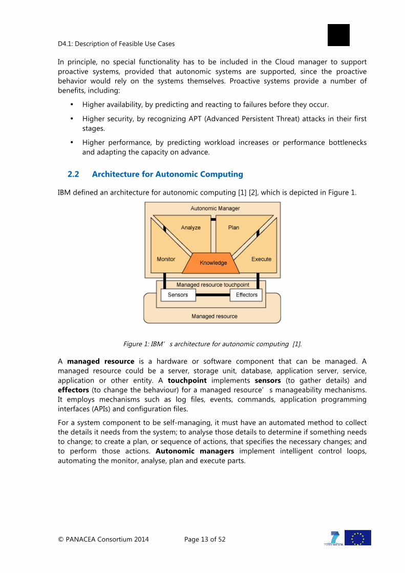
IBM defined an architecture for autonomic computing [1] [2], which is depicted in Figure 1.
Figure 1: IBM’s architecture for autonomic computing [1].
A managed resource is a hardware or software component that can be managed. A managed resource could be a server, storage unit, database, application server, service, application or other entity. A touchpoint implements sensors (to gather details) and effectors (to change the behaviour) for a managed resource’s manageability mechanisms. It employs mechanisms such as log files, events, commands, application programming interfaces (APIs) and configuration files.
For a system component to be self-managing, it must have an automated method to collect the details it needs from the system; to analyse those details to determine if something needs to change; to create a plan, or sequence of actions, that specifies the necessary changes; and to perform those actions. Autonomic managers implement intelligent control loops, automating the monitor, analyse, plan and execute parts.

D4.1: Description of Feasible Use Cases
© PANACEA Consortium 2014 Page 14 of 52
2.3 ML Framework for a proactive autonomic management of cloud resources
PANACEA will propose innovative solutions for a proactive autonomic management of cloud resources, which will be based on a set of advanced Machine Learning (ML) techniques and virtualization. The ML techniques will allow predicting the failure time of user applications running on Virtual Machines (VM) and the violation of expected response time of services. Thanks to its prediction capabilities, PANACEA will realize the autonomic properties:
• self-healing against anomalies by recovering from multiple node and link failures, and using proactive rejuvenation of applications and servers for preventing crashes and increasing the availability, predicting the threshold violation of response time of servers,
• self-configuring by efficiently mapping user's requirements onto distributed clouds and configuring on-the-fly in the presence of anomalies,
• self-optimizing using proactive migration of virtual machines from one cloud resource to another, maintaining the quality of service of end-to-end flows,
• self-protecting using proactive reconfiguration of overlay networks to protect against DDoS attacks.
Figure 2: Machine Learning Framework.
A key innovation of PANACEA is the proposed ML framework, which is described in Figure 2. It will be used for monitoring the utilization of cloud resources and create Knowledge Sources for predicting the time to crash of cloud applications and response time of servers. It will demonstrate the reduction of the monitored parameters by means of Lasso

D4.1: Description of Feasible Use Cases
© PANACEA Consortium 2014 Page 15 of 52
regularization. The goal is to achieve a low value of the prediction error for applications running in a quite dynamic environment and a under a heavy workloads. The popular WEKA ML and data mining package, version 3.5.8 [6] will be used, as well as some extensively used ML methods: M5P, Linear Regression, Support Vector Machine [4] and Support Vector Machines Classifiers [5].

D4.1: Description of Feasible Use Cases
© PANACEA Consortium 2014 Page 16 of 52
3 APPLICATION SCENARIOS
In this chapter, we present the vertical use cases that we studied in order of preference for implementation. Section 3.1 describes the use case proposed by IRIANC which is about cloud web hosting. Section 3.2 is devoted to the second use case. This use case was proposed by ATOS and is based on the concept of“ Data Analytics as a Service. The third use case, proposed by IBM, is directly related to the FP7 project COMPOSE. This use case deals with an IoT (Internet of Things/Services) cloud. It is described in Section 3.3. Finally, the last use case is devoted to mobile telecommunications on the cloud. It was proposed by Imperial and it is described in Section 3.4. For each of these use cases, we briefly describe the application domain, analyse the benefits that could be expected in this domain from proactively managed clouds, and discuss the relevance to PANACEA. We also indicate how we could experimentally validate the outcomes of PANACEA with these use cases. Finally, in Section 3.5, we justify the choice of the first two use cases for experimentation.
3.1 First Use Case: cloud web hosting
3.1.1 Cloud web hosting
The application domain of this Use Case is web hosting. Cloud web hosting is gaining in popularity because it offers several advantages with respect to dedicated servers. The scalability, immediacy and the cost savings offered by cloud web hosting allow customers to efficiently run their website. They can grow and shrink the available resources per their needs. They can get what they need when they need it and they only pay for what they use. This allows customers to concentrate on running their websites, without worrying about the hosting solution. As a consequence, more and more web applications are realized on the cloud.
3.1.2 Benefits expected from a proactive managed cloud
Web servers' reliability, availability and security are prime concerns for most of the businesses. As of July 2011, Apache is running over 235 millions Internet Servers. That is almost each 2 out of any 3 HTTP servers on Internet. The number of users is marking a steady increase too. According to Internet World Statistics the number of people with Internet access, as of March 2011, is over 2 billions. There are a lot of organizations, which prime service is testing and performance measuring of an Internet service (cloud computing, data storage, hosting providers, content delivery, application performance management, etc.) Since websites are now a critical component for most of the businesses, and since websites are increasingly hosted on the cloud, improving the availability and reliability of cloud web hosting will have a significant economical impact. The expected impact of PANACEA in this domain is an increased resilience and reliability for the customer, and lower operating costs for the cloud provider.

D4.1: Description of Feasible Use Cases
© PANACEA Consortium 2014 Page 17 of 52
3.1.3 Relevance of this Use Case to PANACEA
This Use Case is highly relevant for PANACEA since cloud web hosting represents nowadays one of the primary usage of cloud computing infrastructures. As described in more details in Section 4.1, we propose to experiment with this use case through the simulation of an on-line bookstore using a multi-tier e-commerce website. In this experiment, the Java version of a MySQL database server and an Apache Tomcat web server will be used, as well as the standard configuration of TPC-W benchmark [8] to generate HTTP requests. In this experiment, memory leaks of random sizes will be injected by each request.
With this use case, we could validate that we are able to correctly predict the time to crash and response time of web servers, even when they are running in a quite dynamic environment and a under a heavy workload. This scenario could also be used to demonstrate the reduction of the number of monitored parameters thanks to Lasso regularization. In addition, this use case will be invaluable in demonstrating that we can significantly increase the availability of web applications by means of software rejuvenation.
This use case is by far the simplest of the proposed ones, both in terms of availability of data for training the ML algorithms and in terms of implementation feasibility. Even though it does not enable to validate the whole PANACEA middleware, it will enable to validate the proposed ML techniques, which are at the core of the PANACEA innovations. This use case is therefore to be understood as a first stage validation, a more complex application scenario being considered for the validation of all PANACEA technologies.
3.2 Second Use Case: Data Analytics as a service
In this section we describe the Data Analytics as a Service (DAaaS) use case provided by Atos to the PANACEA project. This UC presents a complete Data Analytic Cloud service solution based mainly on one proven technology: Apache Hadoop. The use case provides services to collect monitoring data from sensors in a factory, several programed map/reduce algorithms, and an Apache Hadoop installation together with several services and web interfaces to control the whole process. We describe DAaaS platforms in the next section, and then discuss the benefits that are expected from proactively managed resources in this domain in Section 3.2.2. The relevance of this use case to PANACEA is analysed in Section 3.2.3.
3.2.1 Data Analytics as a Service (DAaaS)
In the last years two new technologies emerged as trends that are shaping the new Enterprise Computing world. Those two technologies are Big Data and Cloud Computing. From a functional perspective, these platforms cover the end-to-end capabilities of an analytical solution, from data acquisition to end-user visualization, reporting and interaction.
DAaaS (see Figure 3) is basically an extensible analytical platform provided using a cloud-based delivery model, where various tools for data-analytics are available and can be configured by the user to efficiently process and analyse huge quantities of heterogeneous data.

D4.1: Description of Feasible Use Cases
© PANACEA Consortium 2014 Page 18 of 52
Figure 3: Diagram of the DAaaS platform
Users of the platform will feed their data, or use data coming from external “curated” data sources, and they will get back in return useful analytic insights. Those results are generated by Analytic Apps configured in specific workflows. These workflows are built using an extensible collection of services that implement analytical algorithms, many of them based on Machine Learning techniques.
3.2.1.1 Functional architecture
The functional blocks of the DAaaS architecture are described in Figure 4.
Figure 4: Functional block diagram of the DAaaS platform
There are two groups of components: those related to the run-time aspects of the solution, basically the part that process the data, identified as Runtime Environment; The second group is denominated Workbench Environment and tackles the interaction with the user.
Workbench Environment
The Workbench Environment enables the users to customize the DAaaS solution to their specific needs. This block interprets three different roles:

D4.1: Description of Feasible Use Cases
© PANACEA Consortium 2014 Page 19 of 52
• Data Integrator – This role takes the responsibility of interfacing the existing internal enterprise systems with the DAaaS system.
• Data Scientist – This role takes care of a correct implementation of the analytical capabilities required by an enterprise.
• End User Tools – Tools for the different kind of users that can interact with the system.
Runtime Environment
The following components are described in a logical data flow, from the acquisition to processing and final storage or representation of user data.
• Data Acquisition – Provides web-services to the external world for the acquisition of user raw data or from “curated” data sources.
• Storage – the core data repository is used to store information in the system.
• Processing – since high amounts of data are expected, a distributed processing capability is a must for the system.
• Analytics – Divided into two different components: on one side we have the Analytic Services that implement the different analytics algorithm, and on the other side the Analytic Framework that orchestrates the execution of the different Analytic Services.
• Analytic Apps – Bundles of different Analytic Services combined by on Analytic Framework.
• Visualization / Reporting – Different tools to represent graphically the results coming from the Analytic Framework.
• App Store – High-level collection of functional bundles to the end-users.
3.2.1.2 DAaaS implementation
In the proof of concept performed by Atos, the Siemens XHQ Solution was used as Enterprise Data Source for the DAaaS platform. Figure 5 presents a high level overview of the solution.
Figure 5: Architecture and technologies used in the proposed solution.

D4.1: Description of Feasible Use Cases
© PANACEA Consortium 2014 Page 20 of 52
The Siemens XHQ is an external service to the DAaaS solution. The integration layer just retrieves through web-services the data coming from the XHQ and feeds them to the analytics modules or store them into the HDFS5/HBase6 database.
The data analytics is based on Apache Hadoop7. It can use Map – Reduce algorithms written in Java, Basic Hadoop tools like Pig8 or Hive9, Apache Mahout10 Algorithms. It also offers integration with R11 statistic language. All the data coming from the XHQ service (if it is necessary to store) and the results coming from the data analytics algorithms are stored into an Apache HBase - a distributed, scalable, big datastore.
Finally, the User Interface contains the following modules: the App Store enabling users to configure the different analytics algorithms to be used with their data; the Data Explorer module to see the results coming from the different analysis; And the Monitoring and Control module.
Workflow
The previous structure is designed to manage the following data workflows:
1. Data Capture from XHQ:
• A timer triggers periodically.
• Web Service to access XHQ data model is invoked, using xHQ Web Service API.
• Response from XHQ is received.
• Information from XHQ is validated and stored in HBase no relational database.
2. Algorithm is executed, results sent back to XHQ, using XHQ Web Service API:
• A timer triggers periodically the execution of the Algorithm.
• Execution of the Algorithm.
• Validation of Results.
• Algorithm results are sent to XHQ using XHQ Web Service API.
3. Results sent back to XHQ, using XHQ connector
• XHQ Connector invokes Web Service
• Web Service access last valid algorithm results.
5 http://hadoop.apache.org/docs/r1.2.1/hdfs_design.html 6 http://hbase.apache.org/ 7 http://hadoop.apache.org/ 8 http://pig.apache.org/ 9 http://hive.apache.org/ 10 http://mahout.apache.org/ 11 http://www.r-project.org/

D4.1: Description of Feasible Use Cases
© PANACEA Consortium 2014 Page 21 of 52
3.2.1.3 Adaptation to PANACEA
The complete previous platform is a bit overkill to validate the PANACEA solution. For this use case, we shall therefore consider only a subset of the DAaS platform. In the application scenario under consideration, the implemented services provide different analytic algorithms for evaluating the statistics of values collected from sensors installed in the devices of a factory plant, (i.e. temperature, vibrations, rotational speed, etc.).
The execution of each of these analyses does not require a considerable amount of computational resources. However, when the amount of devices and sensors as well as the number of concurrent requests are growing, the resources should be increased in order to deliver the results in an acceptable time.
The DAaaS consists of the different service packages as shown in Figure 6. The Device Monitoring service is a service providing a graphical user interface and continuously running some scripts to collect sensor data (this corresponds to the User Interface and Integration part of the previous architecture. Also, consider that the sensor data will be simulated from real data to simulate different controlled conditions during the project). Then, there is a set of data analysis services implementing the data analytic algorithms. Finally, all the analytic services share the Threshold Finder library which implements some functions used by the analytic algorithms (these last blocks correspond with Analytics part of the previous architecture block diagram).
Device Monitoring
Sensor Data
Collect
Web User Interface
Analytics Algorithms Services
All Parameters Analysis Temperature
Analysis Rotational
Speed Analysis
Worker
Worker Nodes
Threshold Finder Threshold Finder
Threshold Finder
Figure 6: Block diagram of the solution ported to PANACEA
Figure 7 presents a hypothetical deployment scenario of the previous described application in a Cloud infrastructure.

D4.1: Description of Feasible Use Cases
© PANACEA Consortium 2014 Page 22 of 52
Sensor Input Interface
VM 1
DAaaS Logic Master Hadoop
VM 2
Hadoop Slave
VM 3
Hadoop Slave
VM 4
Hadoop Slave
VM N
Figure 7: Possible deployment configuration
A brief description of each one of those components:
• Sensor Input – It will collect information coming from the sensor of the factories, basically it connects to several web-services datasources.
• Interface – For the users to configure the different algorithms to process the input data to reach some specific result.
• DAaaS Logic – Responsible of coordinate the recollection of data with the configured algorithms configured by the user.
• The three previous components have been deployed to be deployed in the Oracle Glassfish12 J2EE container.
• Master Hadoop – In our UC, Apache Hadoop is going to be used to apply map-reduce algorithms to the incoming data. The Hadoop master will redistribute the work between the different Hadoop Slaves.
• Slave Hadoop – Slave nodes store the incoming data in the Hadoop Database or HDFS and process it. Hadoop is very elastic and the number of slave nodes can be adjusted dynamically according to the amount of work to be done.
As mentioned previously, the figure details a possible deployment example. Each component could be deployed in an independent VM or they can be grouped together into a single one.
3.2.2 Benefits expected from a proactively managed cloud
DAaaS architectures could benefit from proactively managed cloud resources in several respects:
• The underlying technology used in this use case is Apache Hadoop, which by itself is quite resilient and has a high tolerance to failures. If a Hadoop node fails, the data
12 http://www.oracle.com/technetwork/middleware/glassfish/overview/index.html?ssSourceSiteId=ocomde

D4.1: Description of Feasible Use Cases
© PANACEA Consortium 2014 Page 23 of 52
that it is stored in that node has been duplicated in other nodes and the processing of that information can be restarted from scratch. However, this process is quite time-consuming. Indeed, it is first necessary to create a new virtual machine, make a replica of the information to it, and then start the processing service again. PANACEA will have the ability to prevent this situation by creating a new virtual machine and replicating the data before the virtual machine that it is about to fail stops working. This should allow significant time-savings.
• In a typical scenario, a service is offered to different users who are paying for it. Any downtime in the central DAaaS services will prevent the satisfaction of the Software Level Agreements contracted with these users. This should be avoided with PANACEA by predicting when the different interfaces or core logic services are about to fail.
• In this use case, a key component of the architecture is the service that collects data coming from sensors installed in a factory. If for whatever reason the service collecting that information stops working, the map-reduce algorithms will not have a complete dataset as the user desires. Preventing such situations will enormously benefit the final solution.
3.2.3 Relevance of this Use Case to PANACEA
DAaaS represents an ideal application to be executed in a Cloud environment. Its components can elastically grow in a Cloud environment to adapt to the incoming demand from the users, using as many resources as necessary at a given time. The system has to be highly available and should run without any problem as much as possible, as any downtime can have an economic impact on the service provider.
As previously described, our plan is to experiment with this use case is to implement a scenario where data collected from sensors installed in the devices of a factory plant are processed using an Hadoop Map/reduce algorithm. The data used as input for the DAaaS system will be simulated, adding as much data as necessary to stress the system. In this scenario, the system has several critical single points of failure (webservices collecting sensor data, DAaaS Logic, Master Hadoop) that can make it unusable and need to be carefully monitored. In addition, each of the Hadoop Slaves can fail. This will not stop any data analysis, but it will make the time to finish increase significantly. We can simulate the crash of the two main services implemented by Hadoop slaves: TaskTracker (responsible of processing the information) and DataNode (responsible of storing part of the information). This can be accomplished by killing the service and checking whether the Hadoop Master or any of the other slaves is able to see the failure, or by injecting error in the network traffic to see how the system reacts. Finally, we note that all the central services specifically developed for the solution (not the Apache Hadoop software stock) will run in an Oracle Glashfish server. This server can suffer from typical Java apps problems (e.g., memory leaks, out of memory etc.) that can appear when the application is stressed. This could be achieved by sending lots of input data to it.
With this use case, we could validate that we are able to correctly predict the time to crash and response time of the different services (which are more complex than in use case on cloud web hosting). This use case could also be used to demonstrate that we can significantly increase the availability of the system by performing proactive software rejuvenation or VM

D4.1: Description of Feasible Use Cases
© PANACEA Consortium 2014 Page 24 of 52
migration. Considering a large-scale deployment, we could also show that the monitoring techniques developed in PANACEA can scale without compromising the accuracy of the state information. Finally, if we assume that Hadoop slave nodes are distributed over multiple clouds, this use case could help validate the overlay routing mechanisms developed in PANACEA.
3.3 Third Use Case: Internet of Things
This application scenario deals with an IoT (Internet of Things/Services) platform developed in the smart city use case of the FP7 project COMPOSE. We describe in Section 3.3.1 the COMPOSE project as well as its “Smart City Barcelona”use case. We also indicate how we could experiment with this scenario in PANACEA.
3.3.1 The COMPOSE project
The COMPOSE platform aims at enabling new services that can seamlessly integrate real and virtual worlds through the convergence of the Internet of Services with the Internet of Things. Toward this goal COMPOSE, developed an open and scalable marketplace infrastructure, in which smart objects are associated to services that can be combined, managed, and integrated in a standardized way to easily and quickly build innovative applications.
The COMPOSE platform (See Figure 8 below) builds upon existing European research projects and on going standardization activities to provide a comprehensive marketplace framework that will be able to cover the whole service lifecycle by integrating a number of innovative technological enablers in a coherent way. The platform supports novel approaches for virtualising smart objects into services and for managing their interactions. This includes solutions for managing knowledge derivation, for secure and privacy-preserving data aggregation and distribution, and for dynamic service composition advertising and discovering objects' capabilities and service provisioning and monitoring.
The COMPOSE project is building an IoT (Internet of Things/Services) cloud. COMPOSE provides an IoT enabling ecosystem. It allows the users to easily and securely, develop, deploy, share and maintain services based on Internet-connected smart objects. COMPOSE supports the whole service lifecycle.

D4.1: Description of Feasible Use Cases
© PANACEA Consortium 2014 Page 25 of 52
Figure 8: COMPOSE concept
COMPOSE is use case driven, and currently revolves around three use cases:
1. Smart space - Augmented Shopping Experience 2. Smart City – Barcelona 3. Smart Territory - Trentino
For the purpose of PANACEA we are going to select the smart city use cases with a given workload: A set of running services, a fixed number of service objects and users. Performance measurements will be taken over a given time, with the cloud running without the PANACEA proactive management and then again after the proactive management is introduced.
3.3.1.1 Smart City Barcelona
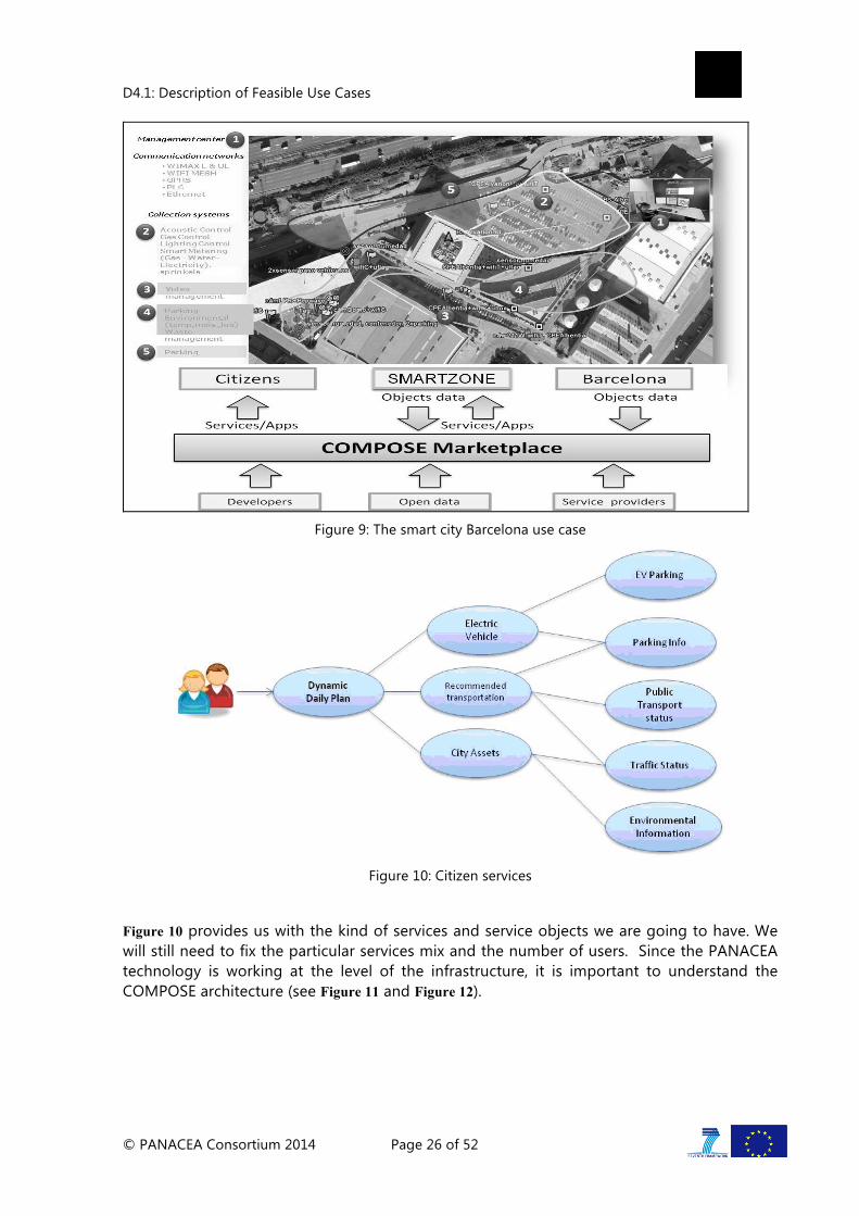
Barcelona was instrumented with a large amount of sensors. The software is focused on the integration of heterogeneous devices and technologies taking advantage of this wide set of existing sensors. Within this city environment we look limit ourselves to services that enhance the day-by-day citizens' experience living in a smart city
D4.1: Description of Feasible Use Cases
© PANACEA Consortium 2014 Page 26 of 52
Figure 9: The smart city Barcelona use case
Figure 10: Citizen services
Figure 10 provides us with the kind of services and service objects we are going to have. We will still need to fix the particular services mix and the number of users. Since the PANACEA technology is working at the level of the infrastructure, it is important to understand the COMPOSE architecture (see Figure 11 and Figure 12).

D4.1: Description of Feasible Use Cases
© PANACEA Consortium 2014 Page 27 of 52
Figure 11: COMPOSE architecture
Figure 12: COMPOSE platform provider perspective
The COMPOSE PaaS is based on the Open Stack IaaS and the Cloud Foundry PaaS infrastructure. For our experiment we are going to setup the physical hardware using a given

D4.1: Description of Feasible Use Cases
© PANACEA Consortium 2014 Page 28 of 52
set of machines. The virtual machines running the various pieces of the software will be deployed on the Cloud Foundry PaaS software that will run on these machines.
3.3.2 Benefits expected from a proactively managed cloud
As illustrated in Figure 12, many services of the COMPOSE platform are cloud-provided. The services presented in Figure 10 are usually not vital for citizens. However, their adoption by a broad proportion of citizens requires a high-level of availability. It should also be emphasized that the disruption of a service (e.g., parking info or public transport status) can have a negative impact on thousands of citizens using this service. As a consequence, the services proposed in the COMPOSE platform could significantly benefit from the innovations developed in PANACEA.
3.3.3 Relevance of this Use Case to PANACEA
As mentioned above, we could experiment with the smart city use cases. In this scenario, a given workload is assumed: a set of running services, a fixed number of service objects and users. Performance measurements could be taken over a given time, with the cloud running without the PANACEA proactive management and then again after the proactive management is introduced.
With this use case, we could in principle validate that we are able to correctly predict the time to crash and response time of the different services. This use case could also be used to demonstrate that we can significantly increase the availability of the system by performing proactive software rejuvenation or VM migration. We note however that in this scenario there is a large variety of services and that they are more complex than those considered in the previous use cases. As a consequence, it would be more difficult to obtain the data for training the ML algorithms. In terms of implementation feasibility, the application scenario is also more difficult to implement.
3.4 Mobile telecommunications on the cloud
This application scenario is about the realization of some of the services ran in mobile networks on the cloud. We describe in Section 3.4.1 the application domain, and analyse the benefits expected from a proactive management in Section 3.4.2. Finally, we discuss the relevance of this use case in Section 3.4.3.
3.4.1 Mobile telecommunications on the cloud
An exemplary application domain that demonstrates how cloud users would benefit from autonomous management of cloud resources is mobile telecommunications on the cloud. A mobile telecommunication network consists of various networking elements and services, some of which are customer-facing whereas others are internal services used by the mobile network itself. While not all mobile network components and services are immediately suitable for virtualization and execution on the cloud, we have identified some cloud-compatible services that the mobile network operator (MNO) will benefit from running on the cloud. We present representative use cases for the PANACEA cloud management framework within this application domain.
D4.1: Description of Feasible Use Cases
© PANACEA Consortium 2014 Page 29 of 52
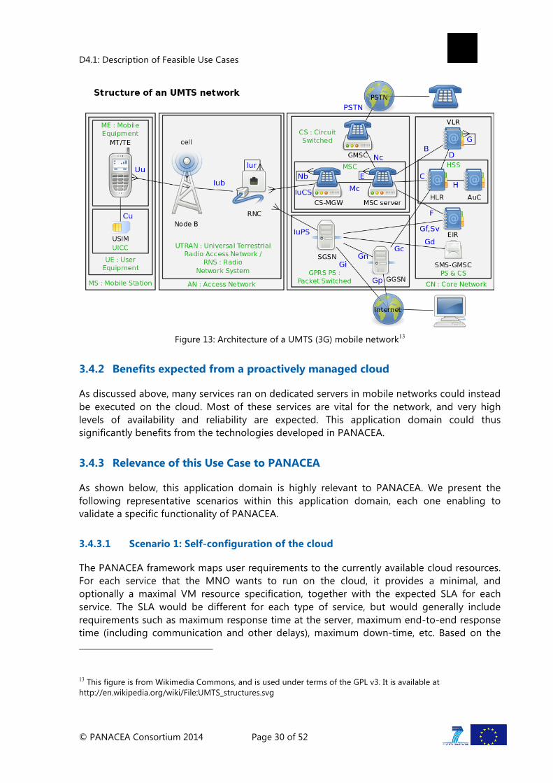
The architecture of a mobile network mainly consists of the radio access network (RAN) and the core network (CN). Figure 13 shows the architecture of a UMTS (3G) network, depicting the components of the mobile device, also known as the user equipment (UE) in 3G networks, radio access network and core network. The radio access network implements a radio access technology, such as W-CDMA, in order to connect the mobile device to the core network. It consists of the base stations and the radio network controller (RNC) in UMTS networks, which carry all user data and signalling between the mobile devices and the core network. While we think that there are opportunities for realizing radio access services on the cloud, these services would need to be hosted by specialized telecommunications equipment that also support virtualization, therefore necessitating a telecommunications-specific cloud. In order to focus on benefits that can be more readily reaped by MNOs from existing cloud hosts that usually employ generic computers, we do not further discuss hosting radio access services on the cloud.
The core network is the central part of a telecommunication network, and it provides all functions needed in order to provide end-user telecommunication services. These functions typically include user authentication, call control and switching, charging, service invocation, and gateway functionality. In addition to these core functions, the core network also provides services that enable the control and configuration of networking elements and services, and the monitoring of the mobile network. These functions constitute the operations and maintenance (O&M) center. The subscriber database, called the HLR or HSS in UMTS networks, is also part of the core network, and is accessed regularly by the core network elements for charging, authentication and service invocation purposes, and by the charging and billing system for end-user billing. The core network also includes supporting networking elements and services that are not specific to mobile networks, such as IP routers, and DNS and DHCP servers.
Although most of the core networking elements is specialized for telecommunications, many of these essentially perform the functionality of a database server, and we propose that all database-like services in the mobile network can be realized on the cloud, with all the benefits that come with a proactively managed cloud, such as reduced cost due to economies of scale, and improved reliability and performance due to intelligent management. Examples of networking elements that would benefit from moving to a cloud environment are the home location register (HLR), the authentication center (AuC), the equipment identity register (EIR), the DNS and DHCP servers, the charging and billing system, and the O&M center. In addition to these mobile network specific services, an MNO also provides customer care services, including a public web page and customer support services where users can access their accounts, see their usage and pay their bills. These customer care services are also ideal candidates for moving to the cloud.
MNOs are naturally concerned with privacy due to legal and business considerations. We therefore think that a private or hybrid cloud model would likely be adopted by an MNO in order to host mobile telecommunications and other support services. An MNO is also likely to use multiple clouds located at geographically different locations in order to locally serve regions covered by their network.
D4.1: Description of Feasible Use Cases
© PANACEA Consortium 2014 Page 30 of 52
Figure 13: Architecture of a UMTS (3G) mobile network13
3.4.2 Benefits expected from a proactively managed cloud
As discussed above, many services ran on dedicated servers in mobile networks could instead be executed on the cloud. Most of these services are vital for the network, and very high levels of availability and reliability are expected. This application domain could thus significantly benefits from the technologies developed in PANACEA.
3.4.3 Relevance of this Use Case to PANACEA
As shown below, this application domain is highly relevant to PANACEA. We present the following representative scenarios within this application domain, each one enabling to validate a specific functionality of PANACEA.
3.4.3.1 Scenario 1: Self-configuration of the cloud
The PANACEA framework maps user requirements to the currently available cloud resources. For each service that the MNO wants to run on the cloud, it provides a minimal, and optionally a maximal VM resource specification, together with the expected SLA for each service. The SLA would be different for each type of service, but would generally include requirements such as maximum response time at the server, maximum end-to-end response time (including communication and other delays), maximum down-time, etc. Based on the
13 This figure is from Wikimedia Commons, and is used under terms of the GPL v3. It is available at http://en.wikipedia.org/wiki/File:UMTS_structures.svg

D4.1: Description of Feasible Use Cases
© PANACEA Consortium 2014 Page 31 of 52
given specifications and SLAs for the requested services, and the current available resources on the clouds and communications between the clouds, the PANACEA framework decides on which VM to instantiate for a given service and where to host the VM. For example, services that need to communicate with low latency might be instantiated on the same host or within the same cloud. Dormant copies of VMs that host services with high availability requirements might be created in order to replace a VM that unexpectedly fails, e.g. due to a physical fault at the host.
3.4.3.2 Scenario 2: Self-optimization of the cloud
Mobile telecommunications services running on the cloud would be subject to dynamic loads due to variable communication patterns of the mobile users. The PANACEA framework continuously monitors the performance of the services and VMs on the cloud and the performance of the cloud hosts and communications. As the load on the services and VMs vary, the framework autonomously optimizes the cloud resources in order to meet the service requirements. The framework can optimize cloud resources by creating new VMs in order to upgrade, downgrade or move existing services.
Upgrading services A service that is observed to have increasing load would usually have increasing response time at the server. The framework detects the increasing response time and predicts that the response time threshold for the service will be reached soon. Before the threshold is reached, the framework instantiates a new VM with more resources in order to replace the current VM. If another service is registered as the load balancer for the upgraded service, then instead of replacing the current VM with the new one, the new VM would be used in addition to the current one, with the load balancer in charge of distributing the requests among the different service instances. Note that the implementation of the load balancing logic is not within the scope of the PANACEA framework.
Downgrading services A service may be downgraded if it is observed to have continuously low load and if the VM hosting the service is significantly over-provisioned for the current load. In this case, the PANACEA framework will create new VM with lower resources, subject to the minimum VM specification for the service, in order to replace the current VM and free cloud resources for other services.
VM migration A VM hosting a service may migrate to another cloud in order to improve performance. For example, if the load on a service is unbalanced in terms of where the load is coming from, which is a very likely scenario in mobile telecommunications services, then performance might be improved by moving the VM hosting the service to a different cloud that has better communication performance with the users of the service. The PANACEA framework will continuously monitor the performance of the services and the VMs, and will decide whether to move the VM running the service to another host or cloud in order to improve its performance.

D4.1: Description of Feasible Use Cases
© PANACEA Consortium 2014 Page 32 of 52
3.4.3.3 Scenario 3: Self-healing of the cloud
The PANACEA framework monitors the performance of services and VMs running on the clouds, especially of the mission-critical services such as the HSS. The framework will detect whether any service or VM is going to fail in the near future by looking at pre-learned signs of previously observed failures, for example increasing memory use and paging. When the framework predicts that a service will fail, a new VM will be created in order to replace the current VM before it fails.
3.4.3.4 Scenario 4: Self-optimization of the communication overlay
In the PANACEA framework, an adaptive communication overlay connects the different clouds used by the MNO. The MNO runs all of its cloud-compatible services across the different clouds. Services running on different clouds frequently communicate with each other in order to provide the services and to keep the consistency of the data. For example, the HSS needs to communicate with the billing system in order get information about which communication services a user can access, especially for pre-paid customers. Similarly, any changes a user makes on their mobile services account through the customer support system needs to be propagated to other services such as the HSS and the billing system.
In this scenario, we assume that congestion increases in the overlay path between two clouds due to third-party factors; this is expected since the communication links connecting the clouds would be shared among multiple users and MNOs. The communication overlay monitors the communications between the clouds, detects the increasing congestion, and predicts that the acceptable latency threshold between two services running on these clouds will be reached soon. The overlay takes action to remedy the situation before the threshold is violated, in the form of finding another overlay path between the two clouds that satisfies the latency requirements, and re-routes the traffic between the services over the new path.
3.4.3.5 Advantages and drawbacks of this use case
As shown above, this use case can give rise to several scenarios illustrating the benefits that can be expected from PANACEA. It also has the advantage of projecting ourselves into the future. Nevertheless, if one wants to go beyond generic database servers, this use case is clearly quite difficult to implement. The availability of data for training ML algorithms is also questionable. As a consequence, we shall not consider this scenario for experimentation.
3.5 Selection of use cases for experimentation
As already mentioned, the use cases selected for experimentation are the first two ones presented in this section. We now justify this choice. Our selection criteria were the followings:
• Impact: the application domain should use services that can be realized on the cloud and that have high availability and reliability requirements.
• Relevance: use cases should enable to validate as many features of PANACEA as possible. Use cases should at least enable to validate the ML techniques for predicting the time to crash of applications and their response-time violations. In addition, they

D4.1: Description of Feasible Use Cases
© PANACEA Consortium 2014 Page 33 of 52
should enable to show that the monitoring methods developed in PANACEA scale without compromising the accuracy of the state information. Finally, they should enable to demonstrate significant improvements to latency, loss rate and throughput can be obtained by using the overlay routing mechanisms of PANACEA.
• Availability of data for training the machine learning algorithms: the machine learning algorithms have to be trained for months, so the number of different services used in a use case should remain fairly low, and these services should not be excessively complex.
• Implementation feasibility: the selected use cases will be used as a part of the test bed activity and help validate the technology produced in the project. Given the time frame devoted to the test bed activity, it is mandatory that use cases do not require an excessive development effort.
Table 1 show the comparison of the four proposed use cases against the above criteria. It summarizes the analysis we did for each use case.
UC1 UC2 UC3 UC4
Impact ✓ ✓ ✓ ✓
Relevance ✓ ✓ ✓ ✓
Availability of data for training the ML algorithms ✓ ✓ ✗ ✗
Implementation feasibility ✓ ✓ ✗ ✗
Table 1: Comparison of proposed use cases against the selection criteria.
In addition to the above criteria, we have also taken into account the benefits of a progressive validation Since ML techniques play a central role in the project, it seems natural to first validate the ML algorithms used for predicting the time to crash of applications and their response-time violations. The first use case on cloud web hosting is intended for that. The precise experimental procedure we will follow is described in Section 4.1. Once these techniques will be validated, we will move to the implementation of the second use case on Data Analytics as a Service (see Section 4.2 for implementation details).

D4.1: Description of Feasible Use Cases
© PANACEA Consortium 2014 Page 34 of 52
4 EXPERIMENTATION WITH SELECTED USE CASES
4.1 Use case on cloud web hosting
We describe below the experimentation that will be performed with this use case. Section 4.1.1 describes the experimental procedure and the expected outcomes. Section 4.1.2 is devoted to the experimental setup.
4.1.1 Experimentation with this use case
In our experiments, a multi-tier e-commerce site that simulates an on-line bookstore, following the standard configuration of TPC-W benchmark [8] will be selected. The Java version of a database server, which is developed by using servlets and MySQL [9], will be used. In this experiment, only memory leaks will be injected at different rates (moderate, aggressive, very slow). For reducing the number of parameters by means of Lasso Regularization Techniques, by applying M5P and SVM ML algorithms, series of experiments will be executed. The proposed ML framework will be realized for reducing the number of the parameters, even in the case of heavier stable workloads (memory leaks and threads injections.) In the mean time, the times to application crash will be predicted for different values of lambda with a small MAE (Max. Absolute Error.) The proposed ML framework allows the prediction of a web server’s response time for different stable workloads: injecting memory leaks and extensive computation loads. As an application server, we will utilize the Apache Tomcat. TPC-W allows us to run a set of experiments using different parameters under a controlled environment. These capabilities will permit to evaluate the proposed techniques for predicting the time to crash and the violation of the response time. To simulate the errors, due to the computer resources exhaustion, we will modify the TPC-W implementation. In the experiments, we will introduce anomalies in two different resources: threads and memory leaks, individually or merged. These two anomalies will be utilized to validate our ML prediction techniques under different scenarios. TPC-W has three types of workloads (Browsing, Shopping and Ordering). We will conduct all experiments by using shopping distribution.
The following set of parameters will be monitored for creating the prediction model: workload, response time, System Load, Disk used, Swap free, Number of Processes, System Memory used, Tomcat Memory Used, Number of Threads, Number of Http Connections, Number of MySql Connections and more available.

D4.1: Description of Feasible Use Cases
© PANACEA Consortium 2014 Page 35 of 52
Figure 14: Diagram of the Django/Apache server experimental setup.
Figure 14 depicts the setup. The server and client run on different virtual machines. The client produced HTTP request at a custom rate lambda. The server responded to each client request with a random-size document. Each response produced a memory leak at the server proportional to the size of the returned document.
4.1.2 Experimental Setup
Our initial experimental setup will utilize HP PROLIANT– DL 385 – Rack Server inside the Private Research Cloud. Eight Virtual Machines (VM1 … VM8) will be installed via a VMware - Workstation by the user of the private research cloud (s). The connections of VMs, internally, within a given Virtual topology (8 nodes), will be realized by the Virtual Switch of VMware, which will allow to create scalable to any size and resilient to partitioning overlay networks.
One of the VM is selected to be Intra ACM, which can be controlled by the Inter ACM for creating federated private clouds. Intra ACM has an access to Hard drives (600 Giga bytes x 6 in total 3.6 Terabytes) for building Training Data set, based on the collected training data from each VM (in our case 6 VMs). The Intra ACM uses the Training Data set for evaluating different Machine Learning (ML) techniques for predicting anomalies (time to fail of application or violation of the response time). The server executes applications under a synthetic workload, which is available as open source software. Anomalies (such as memory leaks and Threads) are injected during the run time of the applications on VMs in the Intra Overlay networks. One VM will be assigned as a stand by spare to demonstrate a seamless execution of running applications using ML techniques for predicting anomalies. The Intra ACM analyzes the Training Data set by means of different ML techniques for creating Prediction models.
In the off-line training phase, we select an “optimal“ ML technique that will reduce the

D4.1: Description of Feasible Use Cases
© PANACEA Consortium 2014 Page 36 of 52
number of the features (parameters) and assign weights to them. The on-line phase will use the reduced set of parameters and allow predicting the time to fail of applications during run time or violation of the response time, in the presence of anomalies. We will use as part of the overlay implementation a “Converge Cast “ technology that will allow us to reduce the traffic generated by the measurements, preventing the flooding between Intra ACM and VMs within Intra overlay, when the virtual topology is mapped on several physical Internet hosts. It will exploit the physical nodes between VM(s) and Intra ACM for aggregating the collected training data sets by each VM, before reaching the Intra ACM.
We expect to demonstrate an increase of availability of web applications at least by 20%. This is the major goal of Panacea project.
4.2 Use case on Data Analytics as a Service
We describe below the experimentation that will be performed with the use case on Data Analytics as a Service. As described in Section 3.2, our plan is to implement a scenario where data collected from sensors installed in the devices of a factory plant are processed using an Hadoop Map/reduce algorithm. The data used as input for the DAaaS system will be simulated, adding as much data as necessary to stress the system. In addition to crashes due to typical Java apps problems, we will also simulate the crash of some services. We specify below how this scenario will be implemented. We distinguish three phases.
4.2.1 User configuring a new analysis of data (DAaaS-UC01)
This use case details the process in which a user comes to the platform, prepares a new analysis configuring from datasources to different algorithms and workflow algorithm to be used.
Actors:
1. Primary Actor – User
2. Secondary Actor – DAaaS platform
Preconditions:
• The VM with the different DAaaS web-services and interface is running.
Flow of Events:
1.1 LOG ON
The user logs on in the DAaaS platform.
1.2 CONFIGURE DATASOURCES
The user configures the different data sources that are going to be used as input data for the map reduce algorithms.
1.3 SELECT ALGORITHMS
The user selects the different algorithms to be used over the incoming data.
1.4 CONFIGURE PROCESSING WORKFLOW
The user configures the different workflow that must follow the different selected

D4.1: Description of Feasible Use Cases
© PANACEA Consortium 2014 Page 37 of 52
algorithms over the incoming data.
1.5 ACTIVATE THE PROCESING TASKS
The user configures the selected workflow and data sources to be executed in the platform.
4.2.2 Processing of the data following an specific workflow (DAaaS-UC02)
After a user configured a new processing task, the system will process the incoming data using a specific workflow and maybe repeating the process periodically if it was requested by the user.
Actors:
1. Primary Actor: DAaaS Platform.
Preconditions:
• An user has already configured one or several tasks into the platform.
• At least a VM is acting as working node (Hadoop Slave).
Flow of Events:
1.1 COLLECTING OF THE DATA FROM DATASOURCES
The DAaaS platform starts collecting the data.
1.2 STORING THE DATA INTO THE HDFS
This data is passed to the Hadoop Master that it is going to be stored into the Hadoop filesystem (HDFS) or Hadoop DB. This data is going to be distributed between all the working nodes (Hadoop slaves) in a resilient way (if a node disappears or stops working, no data is lost).
1.3 CALCULATION OF MAP-REDUCE
The Hadoop Master instructs the Hadoop Slaves to calculate the map-reduce following the algorithms and workflow specified by the user.
1.4 RESULTS ARE STORED IN DATABASE
When the algorithm finishes, results are stored in the database. Input data can be cleaned if it was specified by the user.
Alternate workflow:
The previous case describes a static scenario, where the number of working nodes is static and does not grow depending on the load or space requirements.
2.1 NEED TO DELETE OR ADD NEW HADOOP SLAVE
The calculation process has started or stopped and the DAaaS logic notices that it needs to create or reduce the number of Hadoop nodes. It adds a new VM or deletes a new one and reconfigures the Hadoop master to notice it.

D4.1: Description of Feasible Use Cases
© PANACEA Consortium 2014 Page 38 of 52
4.2.3 Review of the data by an user (DAaaS-UC03)
After an analysis has finished, a user can come and start to review the results.
Actors:
1. Primary Actor – User
2. Secondary Actor – DAaaS platform
Preconditions:
• The VM with the different DAaaS web-services and interface is running.
• Some processing of an specified workflow by the user has finished.
Flow of Events:
1.1 LOG ON
The user logs on in the the DAaaS platform.
1.2 REVIEW OF RESULTS
User looks at the results through a graphical interface.

D4.1: Description of Feasible Use Cases
© PANACEA Consortium 2014 Page 39 of 52
5 OPENNEBULA AND PANACEA
In this chapter, we focus on features that are demanded by the OpenNebula14 community, as a horizontal use case to test and evaluate proactive and autonomic features PANACEA is bringing. For that, we analyse feature requests made by users through the OpenNebula development mailing list15.
Some of the features described in Section 2.1 have been long requested by OpenNebula users and, as shown in the next section, some of them are provided in a non-autonomic way. For example, vertical scaling could be easily performed by using self-configuring features (e.g. to increase CPU power or memory). Also, horizontal scaling could be performed by just requesting more VMs when a given metric exceeds a threshold, therefore systems can manage their elasticity using self-optimizing features. Self-healing and self-protecting features are also demanded by the OpenNebula community. In fact, OpenNebula provides several features for fault tolerance, but providing them in an autonomic and proactive way, through PANACEA, will improve the availability and quality of service.
In Section 5.1, we describe in details some of the existing resource management mechanisms of OpenNebula. A preliminary architecture using these mechanisms to provide a proactive and autonomic resource management is proposed in Section 5.2.
5.1 Interesting OpenNebula Features for PROACTIVE Autonomic Systems
OpenNebula is a cloud computing toolkit for managing heterogeneous distributed data centre infrastructures. The OpenNebula toolkit manages a data centre's virtual infrastructure to build private, public and hybrid implementations of infrastructure as a service [9]. OpenNebula is free and open-source software, subject to the requirements of the Apache License version 2.
We describe below the architecture of OpenNebula, with a particular emphasis on the interfaces it provides. We also address storage and image management, as well as VM management in Sections 5.1.2 and 5.1.3. Networking and monitoring features of OpenNebula are described in sections 5.1.4 and 5.1.5, respectively. Finally, we present authentication and authorization mechanisms of OpenNebula in Section 5.1.6.
5.1.1 Architecture
OpenNebula assumes that the physical infrastructure adopts a classical cluster-like architecture with a front-end, and a set of hosts where Virtual Machines (VM) are executed. There is at least one physical network joining all the hosts with the front-end.
14 http://opennebula.org/ 15 http://lists.opennebula.org/pipermail/dev-opennebula.org) or through the OpenNebula development portal (http://dev.opennebula.org/projects/opennebula/issues

D4.1: Description of Feasible Use Cases
© PANACEA Consortium 2014 Page 40 of 52
Figure 15: Infrastructure for OpenNebula
OpenNebula has been designed to be easily adapted to any infrastructure and easily extended with new components. The result is a modular system that can implement a variety of Cloud architectures and can interface with multiple datacentre services. PANACEA will take advantage of this modularity to implement its Autonomic Cloud Managers.
Figure 16: OpenNebula architecture
As the above figure shows, OpenNebula provides several interfaces that can be used by the Autonomic Cloud Managers:
• Public interfaces enable users to manage VMs, networks and images through a simple and easy-to-use REST API.
• Private interfaces expose extended OpenNebula functionality to private users.
• Native interfaces expose all the functionality of the OpenNebula daemon.
• Driver interfaces perform the interactions between OpenNebula and the Cloud infrastructure, with each driver addressing a particular area.

D4.1: Description of Feasible Use Cases
© PANACEA Consortium 2014 Page 41 of 52
Figure 17: OpenNebula interfaces
5.1.1.1 Public Interfaces
Public interfaces hide most of the complexity of a cloud and are specially suited for end-users. OpenNebula implements two different interfaces, namely:
• OpenNebula EC2. OpenNebula implements the functionality offered by the Amazon's EC2 Query API, mainly those related to VM management. In this way, users can use any EC2 Query tool to access an OpenNebula cloud.
• OpenNebula OCCI. This web service enables users to launch and manage VMs in an OpenNebula installation using the draft 0.8 of the OGF OCCI API specification.
Additionally, rOCCI is an OCCI 1.1 compliant server implementation written in Ruby. It enables users to consume provider specific APIs like the OpenNebula or EC2 API through the Open Cloud Computing Interface. Work on rOCCI started as part of the EU FP7 project SLA@SOI. The goal was to develop an OCCI 1.1 compliant server, which initially supports OpenNebula and can later be easily extended to support other Cloud Frameworks.
5.1.1.2 Private Interfaces
OpenNebula provides the following interfaces for private users:
• CLI: OpenNebula provides a set of commands to interact with the system.
• Sunstone GUI: It is the OpenNebula Cloud Operations Centre, a Graphical User Interface (GUI) intended for regular users and administrators that simplifies the typical management operations in private and hybrid cloud infrastructures.

D4.1: Description of Feasible Use Cases
© PANACEA Consortium 2014 Page 42 of 52
Figure 18: OpenNebula Sunstone
OpenNebula Sunstone can be adapted to different user roles. For example, it will only show the resources the users have access to. Additionally, its behaviour can be customized and extended via views.
5.1.1.3 Native Interfaces
The XML-RPC interface is the primary interface for OpenNebula, and it exposes all the functionality to interface the OpenNebula daemon. Through the XML-RPC interface users can control and manage any OpenNebula resource, including VMs, networks, images, users, hosts and clusters.
The OpenNebula Cloud API (OCA) provides a simplified and convenient way to interface the OpenNebula core. The OCA interface: exposes the same functionality as that of the XML-RPC interface. OpenNebula includes Ruby and Java bindings for OCA.
5.1.1.4 Driver Interfaces
The interactions between OpenNebula and the Cloud infrastructure are performed by specific drivers each one addressing a particular area:
• Storage. The OpenNebula core issue abstract storage operations (e.g. clone or delete) that are implemented by specific programs that can be replaced or modified to interface special storage backends and file-systems. These programs are separated into Datastore drivers, which serve the purpose of managing images: register, delete, and create empty datablocks, and Transfer Manager drivers, that manage images associated to instantiated VMs.

D4.1: Description of Feasible Use Cases
© PANACEA Consortium 2014 Page 43 of 52
• Virtualization. The interaction with the hypervisors is also implemented with custom programs to boot, stop or migrate a VM. This allows administrators to specialize each VM operation so to perform custom operations.
• Networking. Several network drivers restrict network access using packet filtering rules (with iptables and ebtables), 802.1Q VLAN tagging, Open vSwitch or VMware networking.
• Monitoring. Monitoring information is also gathered by external probes. It is possible to add additional probes to include custom monitoring metrics that can be later used to allocate VMs or for accounting purposes
• Authorization. OpenNebula can be also configured to use an external program to authorize and authenticate user requests. In this way, administrators can implement any access policy to Cloud resources.
5.1.2 Storage and Image Management
A datastore is any storage medium used to store disk images for VMs, previous versions of OpenNebula refer to this concept as an image repository. Typically, a datastore will be backed by SAN/NAS servers. An OpenNebula installation can have multiple datastores of several types to store disk images. OpenNebula also uses a special datastore, the system datastore, to hold images of running VMs.
OpenNebula is shipped with 3 different datastore classes:
• System, to hold images for running VMs, depending on the storage technology used these temporal images can be complete copies of the original image, qcow deltas or simple filesystem links.
• Image, to store the disk images repository. Disk images are moved, or cloned to/from the System datastore when the VMs are deployed or shutdown; or when disks are attached or snapshotted.
• Files, to store plain files and not disk images. The plain files can be used as kernels, ramdisks or context files.
Image datastores can be of different type depending on the underlying storage technology: file system, vmfs, LVM or Ceph.
Images are managed by datastore drivers that register, delete, and create empty datablocks. Images registered in a datastore are transferred to the hosts by transfer drivers.
5.1.2.1 Image Formats
OpenNebula natively supports “raw”, qcow2 and VMDK images. In addition, the Contrail and VENUS-C projects have both provided support for the OVF standard.
A raw image consists of a sector-by-sector binary copy of the source medium; the actual format of the file contents will depend on the file system of the disk from which the image was created.

D4.1: Description of Feasible Use Cases
© PANACEA Consortium 2014 Page 44 of 52
qcow (QEMU Copy On Write) is a file format for disk image files used by QEMU, a hosted VM monitor. It uses a disk storage optimization strategy that delays allocation of storage until it is actually needed. Files in qcow format can contain a variety of disk images, which are generally associated with specific guest operating systems.
qcow2 is an updated version of the qcow format, intended to supersede it. The main difference with the original is that qcow2 supports multiple VM snapshots through a new, flexible model for storing snapshots. Users can easily convert qcow disk images to the qcow2 format. QEMU and Xen have retained the qcow format for backwards compatibility.
VMDK (Virtual Machine DisK) is a file format developed by VMware for its virtual appliance products, but is now an open format. The format is a container for virtual hard disk drives to be used in VMs like VMware Workstation or VirtualBox.
OVF (Open Virtualization Format) is a packaging standard designed by DMTF (Distributed Management Task Force) to address the portability and deployment of virtual appliances. OVF enables simplified and error-free deployment of virtual appliances across multiple virtualization platforms.
An OVF package consists of several files placed in one directory. An OVF package always contains exactly one OVF descriptor (a file with extension .ovf). The OVF descriptor is an XML file that describes the packaged VM; it contains the metadata for the OVF package, such as name, hardware requirements, references to the other files in the OVF package and human-readable descriptions. In addition to the OVF descriptor, the OVF package will typically contain one or more disk images, and optionally certificate files and other auxiliary files. The entire directory can be distributed as an OVA package, which is a tar archive file with the OVF directory inside.
5.1.3 VM Management
In OpenNebula the VMs are defined with template files. The Template Repository allows OpenNebula administrators and users to register VM definitions in the system, to be instantiated later as VM instances. These templates can be instantiated several times, and also shared with other users.
The Virtualization subsystem is the component in charge of talking with the hypervisor installed in the hosts and taking the actions needed for each step in the VM lifecycle, like deployment, migration or shutdown.
5.1.3.1 VM Placement
The following attributes establish placement constraints and preferences for each VM:
• SCHED_REQUIREMENTS: Boolean expression that rules out provisioning hosts from list of machines suitable to run this VM.
• SCHED_RANK: This field sets which attribute will be used to sort the suitable hosts for this VM. Basically, it defines which hosts are more suitable than others.
• SCHED_DS_REQUIREMENTS: Boolean expression that rules out entries from the pool of datastores suitable to run this VM.

D4.1: Description of Feasible Use Cases
© PANACEA Consortium 2014 Page 45 of 52
• SCHED_DS_RANK: States which attribute will be used to sort the suitable datastores for this VM. Basically, it defines which datastores are more suitable than others.
The scheduler is configured with a default placement policy: packing, striping, load-aware, custom and fixed for host selection; and packing, striping, custom and fixed for datastore selection.
5.1.3.2 VM Contextualization
OpenNebula provides a method to pass information to a newly created VM, where a CD-ROM image contains a shell script context.sh with custom variables defined on VM start. This information can be the network configuration of the VM, user credentials, initialization scripts and free form data.
To enable the VM images to use the contextualization information written by OpenNebula a series of scripts need to be added to trigger the contextualization process. To simplify the process, a couple of Linux packages do the work (one-context in Ubuntu/Debian or opennebula-context in CentOS/RedHat).
Since version 0.7.3 of cloud-init packages the OpenNebula context CD-ROM is supported. It is able to get and configure networking, hostname, SSH key for root and cloud-init user data.
5.1.3.3 VM Re-sizing
It is possible to re-size the capacity assigned to a VM in terms of the virtual CPUs, memory and CPU allocated. VM re-sizing can be done when the VM is not ACTIVE, and so in any of the following states: PENDING, HOLD, FAILED and especially in POWEROFF.
The following procedure is recommended:
1. Perform any operation needed to prepare the VM for shutting down (e.g. manually stop some services).
2. Power off the VM.
3. Re-size the VM.
4. Resume the VM using the new capacity.
Using this procedure the VM will preserve any resource assigned by OpenNebula (e.g. IP leases).
5.1.3.4 Hot Plugging of Devices
New disks can be hot-plugged to running VMs with the onevm disk-attach and disk-detach commands. Also, it is possible to hotplug network interfaces to a running VM.
5.1.3.5 VM Backup and Recovery
It is possible to take a snapshot of a VM disk to preserve or backup its state at a given point of time. There are two types of disk snapshots in OpenNebula:

D4.1: Description of Feasible Use Cases
© PANACEA Consortium 2014 Page 46 of 52
• Deferred snapshots, changes to a disk will be saved as a new Image in the associated datastore when the VM is shut down. The new image will be locked till the VM is properly shut down and the transferred from the host to the datastore.
• Live snapshots, just as the deferred snapshots, but the disk is copied to the datastore the moment the operation is triggered. Therefore, the disk must be in a consistent state during the copy operation (e.g. by unmounting the disk from the VM). While the disk is copied to the datastore the VM will be in the HOTPLUG state.
5.1.3.6 High Availability
Failures are categorized depending on whether they come from the physical infrastructure (Host failures) or from the virtualized infrastructure (VM crashes). In both scenarios, OpenNebula provides a cost-effective failover solution to minimize downtime from server and OS failures.
When OpenNebula detects that a host is down, a hook can be triggered to deal with the situation. OpenNebula comes with a script out-of-the-box that can act as a hook to be triggered when a host enters the ERROR state. This can very useful to limit the downtime of a service due to a hardware failure, since it can redeploy the VMs on another host.
The VM lifecycle management can fail in several points. The following two cases should cover them:
• VM fails: This may be due to a network error that prevents the image to be staged into the node, a hypervisor related issue, a migration problem, etc. The common symptom is that the VM enters the FAILED state. In order to deal with these errors, a VM hook can be set to “recreate” the failed VM (or, depending the production scenario, delete it).
• VM crash: This point is concerned with crashes that can happen to a VM after it has been successfully booted (note that here boot doesn't refer to the actual VM boot process, but to the OpenNebula boot process, that comprises staging and hypervisor deployment). OpenNebula is able to detect such crashes, and report it as the VM being in an UNKNOWN state. This failure can be recovered from using the onevm boot functionality.
5.1.3.7 Multi-tier Systems and Auto-scaling
OneFlow allows users and administrators to define, execute and manage multi-tiered applications, or services composed of interconnected VMs with deployment dependencies between them. Each group of VMs is deployed and managed as a single entity, and is completely integrated with the advanced OpenNebula user and group management.
A service is composed by roles, each one corresponding to one VM template and each one with certain cardinality, i.e. the number of instances of the same VM template. The cardinality of a given role can be adjusted manually, based on metrics, or based on a schedule.
When a scaling action starts, the Role and Service enter the SCALING state. In this state, the Role will instantiate or shutdown a number of VMs to reach its new cardinality. A role with elasticity policies must define a minimum and maximum number of VMs.

D4.1: Description of Feasible Use Cases
© PANACEA Consortium 2014 Page 47 of 52
After the scaling, the Role and Service are in the COOLDOWN state for the configured duration. During a scale operation and the cooldown period, other scaling actions for the same or for other Roles are delayed until the Service is RUNNING again.
5.1.3.8 Cloud Bursting
Cloud bursting is a model in which the local resources of a Private Cloud are combined with resources from remote Cloud providers. The remote provider could be a commercial Cloud service, such as Amazon EC2, or a partner infrastructure running a different OpenNebula instance. Such support for cloud bursting enables highly scalable hosting environments.
The remote cloud provider will be included in the OpenNebula host pool like any other physical host in the infrastructure.
5.1.4 Networking
When a new VM is launched, OpenNebula will connect its network interfaces (defined in the NIC section of the template) to the bridge or physical device specified in the Virtual Network definition. This will allow the VM to have access to different networks, public or private.
This mechanism is complemented with Virtual Network Manager drivers, than can protect networks with firewall rules or isolate them with several network access control mechanisms.
5.1.4.1 Network Protection
The fw Virtual Network Manager driver applies firewall rules to filter TCP, UDP or ICMP traffic. This driver installs iptables rules in the physical host executing the VM and can be used to filter (and enforce) TCP and UDP ports, and to define a policy for ICMP connections, without any additional modification to the guest VMs.
5.1.4.2 Virtual Network Isolation
OpenNebula provides other Virtual Network Manager drivers providing mechanisms to restrict network access only to the expected VMs, to avoid situations in which an OpenNebula user interacts with another user's VM. The OpenNebula administrator may associate one of the following drivers to each Host:
• 802.1Q: restrict network access through VLAN tagging, which also requires support from the hardware switches.
• ebtables: restrict network access through ebtables rules. No special hardware configuration required.
• ovswitch: restrict network access with Open vSwitch Virtual Switch.
• VMware: uses the VMware networking infrastructure to provide an isolated and 802.1Q compatible network for VMs launched with the VMware hypervisor.
These drivers also enable the firewalling rules to allow a regular OpenNebula user to filter TCP, UDP or ICMP traffic.

D4.1: Description of Feasible Use Cases
© PANACEA Consortium 2014 Page 48 of 52
5.1.4.3 Virtual Router
OpenNebula also comes with a Virtual Router appliance. When instantiated in a network, this appliance provides the following services for other VMs running in the same network:
• Router (masquerade)
• Port forwarding
• DHCP server
• RADVD server
• DNS server
A big advantage of using this appliance is that VMs can be run in the same network without being contextualized for OpenNebula.
5.1.5 Monitoring
The Information Manager (IM) is in charge of monitoring the hosts. It comes with various sensors or probes, each one responsible of different aspects of the computer to be monitored (CPU, memory, hostname…). Also, there are probes prepared to gather information from different hypervisors. A probe is a little script or binary that extracts information remotely (SSH) or locally (SH) and returns it in a simple NAME=VALUE format.
In the pull model, OpenNebula periodically actively queries each host and executes the probes via SSH. In KVM and Xen this means establishing an SSH connection to each host and executing several scripts to retrieve this information. VMware uses the VI API for this, instead of a SSH connection. This mode is limited by the number of active connections that can be made concurrently, as hosts are queried sequentially.
In the UDP-push model, which is the default for KVM and Xen from OpenNebula 4.4, each host periodically sends monitoring data via UDP to the frontend, which collects it and processes it in a dedicated module. This distributed monitoring system resembles the architecture of dedicated monitoring systems, using a lightweight communication protocol, and a push model. This model is highly scalable and its limit (in terms of number of VMs monitored per second) is bounded to the performance of the server running oned and the database server.
5.1.5.1 Application Monitoring
OneGate allows VM guests to push monitoring information to OpenNebula. Users and administrators can use it to gather metrics, detect problems in their applications, and trigger OneFlow elasticity rules.
OneGate is a server that listens to HTTP connections from the VMs. OpenNebula assigns an individual token to each VM instance, and applications running inside the VM use this token to send monitoring metrics to OneGate.
When OneGate checks the VM ID and the token sent, the new information is placed inside the VM's user template section. This means that the application metrics are visible from the command line, Sunstone, or the APIs.

D4.1: Description of Feasible Use Cases
© PANACEA Consortium 2014 Page 49 of 52
OneGate is very similar to Amazon CloudWatch. Therefore, a solution based on this mechanism could be easily ported. The OpenNebula documentation includes a tutorial about the use of OneGate.
5.1.6 Authentication and Authorization
OpenNebula comes by default with an internal user/password authentication system, but it is possible to enable an external Authentication driver for SSH, LDAP or X.509.
The OpenNebula ACL authorization system enables fine-tuning of the allowed operations for any user, or group of users. This allows administrators to tailor the user roles according to their infrastructure needs. Each operation generates an authorization request that is checked against the registered set of ACL rules. The core then can grant permission, or reject the request.
5.2 Proposed Architecture and Features for OpenNebula to Support Proactive Autonomic Systems
In this case, the managed resource is not an individual resource, but a whole virtualized infrastructure managed by OpenNebula, which acts as the touchpoint, providing interfaces for sensors and effectors.
The autonomic manager (i.e. Intra-ACM in PANACEA) communicates with OpenNebula through its native interface (i.e. XML-RPC). It receives monitoring information from OpenNebula and performs autonomic operations on behalf of the VMs. VMs can provide additional, application-level metrics through the OneGate service. This is the approach taken by the OneFlow service (using XML-RPC) to perform auto-scaling.
Users access the functionality through public or private interfaces. Private interfaces (Sunstone GUI and CLI) are the most powerful (full functionality and information). Public interfaces (OCCI) provide limited functionality and information, but they can be used remotely.

D4.1: Description of Feasible Use Cases
© PANACEA Consortium 2014 Page 50 of 52
Figure 19: Architecture for Autonomic Computing with OpenNebula.
The autonomic manager performs all the stages of the intelligent control (or MAPE-K) loops. However, some of these stages could be performed by services running on VMs. These services would use OneGate to perform requests (as an effector mechanism). In this case, monitoring information could be gathered directly from the cloud monitoring system (as a sensor mechanism).
Initially, images will be stored in native format, but OVF will be progressively adopted in order to benefit portability. Similarly, a native contextualization process will be used first, but a more standardized one, like cloud-init, can be adopted in later stages of the project, also for portability reasons.
Regarding self-configuring features, systems can change some configuration parameters (capacity, placement, connectivity...) in OpenNebula (some of them at runtime, some of them require a shutdown) using different private or public interfaces, depending on if it is an on-premises cloud or an external cloud, respectively. The number of configuration parameters that can be changed (preferably at runtime) will be extended. Additionally, OpenNebula also provides some features for hot plugging of devices, which will be revised and extended as needed.
Regarding self-healing features, OpenNebula already provides fault detection and recovery capabilities. Recovery is performed by executing host and VM hooks associated to a failure status. The deployment of spare VMs allows for application live migration or software rejuvenation.
Regarding self-optimizing (or self-adapting) features, systems can get information from OpenNebula about the execution environment at runtime (self-awareness) using a native interface or accessing the monitoring system directly. Also, OneGate provides a communication mechanism for VMs running inside the cloud using a simple credential delegation mechanism (security token). With that information, systems can adapt to the environment using self-configuration features. For example, they can manage elasticity. Elasticity is currently managed by OpenNebula with OneFlow, which can use information gathered by OneGate.
Regarding self-protecting features, OpenNebula already provides ways to define and manage access control and protection, like ACLs, firewalls, VLANs… It also provides backup and recovery operations for VMs, since it is able to suspend and resume VMs or take snapshots of their status.
Finally, regarding proactivity, OpenNebula can be classified as a reactive Cloud manager, not providing any feature to predict or react to future anomalies.

D4.1: Description of Feasible Use Cases
© PANACEA Consortium 2014 Page 51 of 52
6 CONCLUSIONS
We covered in this document the use cases that we studied and considered for demonstrating the proactive management capabilities that we are developing in PANACEA. We first presented four vertical use cases. The first objective was to gather requirements from different application domains so as to better define the scope of the project and the technologies that will be developed. The second objective was to identify the most relevant use cases for experimentation. The development of the Machine Learning technology and the need to demonstrate the improvements to the system, dictate use cases that on one hand have enough generated data for the Machine Learning algorithms and on the other hand allow us to run the experiment under a controlled setting. We shall therefore use the Multi-tier E-Commerce application described in Section 4.1 for a first stage validation, and then use the Hadoop Map/Reduce scenario described in Section 4.2 for the validation of the whole PANACEA solution. We also presented an horizontal use case focused on OpenNebula. The objective was to identify the OpenNebula resource management mechanisms on top of which we can build our architecture for proactive and autonomic computing.

D4.1: Description of Feasible Use Cases
© PANACEA Consortium 2014 Page 52 of 52
REFERENCES
[1] J. O. Kephart, D. M. Chess: "The vision of autonomic computing”, Computer 36 (1): 41-50, 2003. http://dx.doi.org/10.1109/MC.2003.1160055
[2] A. G. Ganek, T. A. Corbi: "The dawning of the autonomic computing era”, IBM Systems Journal 42 (1): 5-18, 2003. http://dx.doi.org/10.1147/sj.421.0005
[3] http://www.irianc.com
[4] C. Cortes and V. Vapnik, ”Support-vector networks”, Machine Learning vol. 20, pp. 273–297, 1995.
[5] V. N. Vapnik, “Support Vector Machines Classifiers (SVM-C)”, Statistical Learning Theory. Wiley-Interscience, 1998.
[6] WEKA 3.5.8. http://www.cs.waikato.ac.nz/ml/weka/
[7] R. Teixeira, K. Marzullo, S. Savage, and G. Voelker, Characterizing and measuring path diverisy in Internet topologies In Proceedings of ACM SIGMETRICS (extended abstract), 2003.
[8] Z. Jerzak, R. Fach and C. Fetzer, Fail-Aware Publish/Subscribe, In 6th IEEE International Symposium on Network Computing and Applications, Cambridge, MA, USA, 12-14 July 2007
[9] R. Moreno-Vozmediano, R. S. Montero, I. M. Llorente: “IaaS Cloud Architecture: From Virtualized Datacenters to Federated Cloud Infrastructures”. IEEE Computer 45 (12): 65-72, 2012. http://dx.doi.org/10.1109/MC.2012.76