D. UNDERNEATH BUS 1. Front Suspension Inspection ...
51
D. UNDERNEATH BUS 1. Front Suspension Inspection Procedures: Repair (or note) if: Out of Service if: a. Wheel Bearings Inspect front wheel bearings and related components for condition and proper adjustment of bearings. With front wheels raised (wheels unloaded), grasp tire and attempt to rock wheel to check for movement. Spin tire to check for noise and condition of bearings. NOTE: It is important to correctly identify the source of any play. To determine if the play is in wheel bearings, have an assistant fully apply brakes while rechecking play. If movement disappears with brakes applied, then play was in wheel bearings. b. I-Beam Inspect I-beam axle assembly. 114 There is minor seepage of oil or grease around dust cover (repair). (Continued on Next Page) There is dripping of oil or grease around dust covers. Dust cover or fasteners are missing or loose. Any noise, binding, or roughness is discovered in bearings. Wheel bearing, end play exceeds manufacturer’s specifications (maximum of .010” in and out play measured at bearing hub). I-beam has been cut, modified, or is damaged. There is any bluing or other evidence that I- beam has been heated. Supp. 03-1
Transcript of D. UNDERNEATH BUS 1. Front Suspension Inspection ...

D. UNDERNEATH BUS 1. Front Suspension
Inspection Procedures: Repair (or note) if: Out of Service if:
a. Wheel Bearings
Inspect front wheel bearings and related components for condition and proper adjustment of bearings. With front wheels raised (wheels unloaded), grasp tire and attempt to rock wheel to check for movement. Spin tire to check for noise and condition of bearings.
NOTE: It is important to correctly identify the source of any play. To determine if the play is in wheel bearings, have an assistant fully apply brakes while rechecking play. If movement disappears with brakes applied, then play was in wheel bearings.
b. I-Beam
Inspect I-beam axle assembly.
114
There is minor seepage of oil or grease around dust cover (repair).
(Continued on Next Page)
There is dripping of oil or grease around dust covers.
Dust cover or fasteners are missing or loose.
Any noise, binding, or roughness is discovered in bearings.
Wheel bearing, end play exceeds manufacturer’s specifications (maximum of .010” in and out play measured at bearing hub).
I-beam has been cut, modified, or is damaged.
There is any bluing or other evidence that I-beam has been heated.
Supp. 03-1
D. UNDERNEATH BUS 1. Front Suspension
Inspection Procedures: Repair (or note) if: Out of Service if:
c. King pins
Inspect king pin assemblies for condition and play as follows:
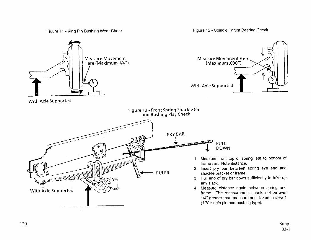
1) With front wheels raised, grasp tire at top and bottom or using a pry bar for leverage attempt to move the wheel assembly in and out. (See Figure 11, page 120.)
NOTE: Wheel bearings must be adjusted properly (or wheel bearing play must be eliminated by locking brakes) before checking king pins.
2) Place a pry bar under wheel and lift tire straight up and down to determine condition of thrust bearing.
115
Locking pin is loose (repair).
End cap O-rings or bolts are loose or missing (repair).
(Continued on Next Page)
Locking pin is backing out, or missing.
King pin movement is more than 1/4 inch measured at outside edge of tire (see Figure 11, page 120).
Vertical (up and down) play in king pin assembly is greater than .030” (see Figure 12, page 120), and/or thrust bearing is damaged or missing.
NOTE: If play is beyond specifications, wear may be king pin, axle eye, and/or King pin bushings. Vehicle should be grounded if side play at outside edge of tire is greater than 1/4 inch. Do not tighten king pin lock (if equipped) or grease king pin before inspecting King pin assembly play.
Supp. 03-1
D. UNDERNEATH BUS 1. Front Suspension
Inspection Procedures: Repair (or note) if: Out of Service if:
d. Shackles
Inspect condition of shackles, spring hangers, and pinch bolts.
e. Spring Mounts
Inspect spring mount bracket(s) for condition and securement.
Any front spring shackle or hanger is cracked or broken.
Any front spring shackle or hanger has significant side wear at spring eye.
Any front spring shackle or hanger is worn, or pinch bolt is stripped or missing, so that spring pin cannot be clamped tightly.
Any front spring mount is broken or cracked.
Any front spring mount-to-frame fastener is loose or missing.
Frame is cracked at any spring mounting location.
(Continued on Next Page)
116 Supp. 03-1
D. UNDERNEATH BUS 1. Front Suspension
Inspection Procedures: Repair (or note) if: Out of Service if:
f. Pins and Bushings
Inspect pins and bushings as follows:
Inspect front spring pins and bushings for wear and lubrication. Check for wear with front axle loaded. Insert pry bar between spring eye and fixed point at frame and pull down. Measure total free play in pins and bushings (see Figure 13, page 120).
g. A-Frames and Bushings
Inspect A-frames and bushings for condition and securement.
117
Any spring pin assembly will not accept lubrication, or zerk (grease) fitting is damaged or missing (repair).
Rubber bushing(s) are split, badly deteriorated, or badly extruded from suspension joints (repair).
(Continued on Next Page)
Total free play (up and down) of pins and bushings exceeds 1/4 inch (2 pin type) or 1/8 inch (1 pin type). (See Figure 13, page 120.)
Inner sleeve or rubber bushing type spring pin assembly or assemblies are worn through, or rubber bushing is excessively worn (rubber is compacted or deteriorated, resulting in free play between rubber and spring eye or inner sleeve).
Rubber bushing(s) are missing.
Any A-frame assembly is bent, damaged, broken, or any fasteners are loose or missing.
Any A-frame, bushing, or pivot arm has more than .050” free play at pivot point.
Mounting of bushing assembly or assemblies are not secure.
Supp. 03-1
D. UNDERNEATH BUS 1. Front Suspension
Inspection Procedures: Repair (or note) if: Out of Service if:
h. Ball Joints
Inspect ball joint(s) for condition, securement, and lubrication.
i. U-Bolts
Inspect spring U-bolts for condition and securement.
j. Shocks
Inspect shocks for condition and securement.
118
Zerk (grease) fitting is missing or damaged, or ball joint will not take lubrication (repair).
Any U-bolt(s) is misaligned (repair).
(Continued on Next Page)
Any ball joint has more than 3/32-inch axial play.
Any ball joint nut is loose or missing, or cotter pin is missing.
Ball joint to A-frame mounting is cracked or loose, or has been welded.
There is rust underneath U-bolt nuts indicating possibility of looseness.
Any U-bolt, seating plate, shock mount bracket, or nut is loose or missing, cracked, or stripped.
There is wetness around shock body due to leaking shock fluid.
Any shock mounting or fastener is loose, missing, cracked, or broken.
Any shock is broken.
Any shock fails to function.
Supp. 03-1
D. UNDERNEATH BUS 1. Front Suspension
Inspection Procedures: Repair (or note) if: Out of Service if:
k. Springs
Inspect front springs for condition, securement, and alignment.
l. Wheel Seals
Check for condition and leakage.
119
There are any loose, missing, broken or worn springs clips (repair).
Any coil or leaf spring has flattened, and ride height is less than manufacturer’s specifications (repair).
Either front spring saddle (if equipped) is worn out or missing (repair).
Rubber bumper is missing (repair).
Any leaf spring(s) is broken, cracked, or missing.
Spring eye is worn or spread such that bushings are loose in spring eye.
Any coil spring(s) is broken, insecurely mounted, non-O.E.M. or non-O.E.M. blocks or spacers are installed.
There is any misalignment of spring leaves or other evidence that center pin is loose or broken.
Either front coil or leaf spring is worn so that rubber frame bumper is damaged or worn due to frequent bottoming of front suspension.
Any alignment wedge is loose or damaged.
On any air bag type spring assembly, air bag is damaged or leaking.
Either front wheel seal is damaged or leaking.
Supp. 03-1
120 Supp. 03-1
D. UNDERNEATH BUS 2. Front Brakes
Inspection Procedures: Repair (or note) if: Out of Service if:
a. Brake Hoses
Inspect front brake flexible hoses for condition, securement, and routing.
b. Lines
Inspect air and hydraulic brakes lines for routing, securement, and condition.
121
Brake line bracket(s) or securement system is loose or missing (repair).
(Continued on Next Page)
Any front brake flex hose or connection is leaking fluid or air pressure.
Any front brake flex hose is kinked, collapsed, bulging, has damaged plies or cord, or is damaged below outer covering.
Any front brake flex hose supporting brackets are damaged or have loose fasteners.
Any front brake flex hose is rubbing on or routed against other components.
Any brake line is bent, crimped, or damaged significantly restricting air pressure or hydraulic fluid.
Any brake line or connection is leaking air pressure or hydraulic fluid.
Supp. 03-1
D. UNDERNEATH BUS 2. Front Brakes
Inspection Procedures: Repair (or note) if: Out of Service if:
c. Chambers
Inspect front brake chamber assembly or assemblies for securement, condition, and proper size.
d. Slacks
Inspect slack adjusters and S-cam assemblies for wear, condition, operation, and securement.
NOTE: See Section D.2.j., page 126 on brake adjustment for procedure to check operation of Automatic Slack Adjusters (ASA).
122
Slack adjuster is mounted so that adjuster bolt is facing chamber (repair).
(Continued on Next Page)
Any brake line is rubbing on other components or is abraded.
Any brake line is not of O.E.M. material, size, or type.
Any chamber-mounting bracket is cracked, bent, or broken.
Any front brake chamber or mounting fastener is damaged or loose.
Either chamber is not original size, or size of chambers is not matched left and right (both sides same size).
Any portion of slack adjuster or S-cam is missing, broken, cracked, or badly worn.
S-cam shaft and/or S-cam bushing total wear (up and down) is greater than .040-inch (see Figure 14, page 127).
S-cam in and out endplay is more than .060-inch (see Figure 14, page 127).
Supp. 03-1
D. UNDERNEATH BUS 2. Front Brakes
Inspection Procedures: Repair (or note) if: Out of Service if:
e. Pushrods
Inspect pushrod assembly or assemblies for condition, securement, and alignment.
f. Linings
Inspect linings and foundation brake hardware for contamination, wear, damage, and securement.
123
Lining wear is extremely uneven left and right (repair).
(Continued on Next Page)
S-cam snap ring is missing.
Slack adjuster has frozen or stripped worm gear or ratchet assembly.
Any portion of pushrod assembly (locknut, pushrod, clevis and pin, or cotter pin) is loose, missing, or damaged.
Pushrod is rubbing against body of chamber, or chamber is misaligned.
Pushrods on left and right sides are not mounted in identical (same) slack adjuster location hole (same effective slack adjuster length).
Front brake lining (riveted type shoe) is less than 3/16-inch thick (Q-type), or ¼ inch (Qplus-type), above metal of shoe (shoe table) at the center of the shoe.
For bonded type linings, front brake lining is worn to within 1/16 inch of shoe table (face of shoe).
Front brake lining is worn to within 1/16-inch of any rivet or bolt head.
Supp. 03-1
D. UNDERNEATH BUS 2. Front Brakes
Inspection Procedures: Repair (or note) if: Out of Service if:
Any foundation brake assembly does not have at least one (1) lining inspection hole.
Lining is broken, cracked, or loose on shoe.
Friction surface is contaminated grease, or brake fluid.
There is any shimming lining and shoe.
Lining is not proper size.
material
with oil,
between
Shoe platform or webbing is cracked or damaged.
There is any loose, damaged, or missing foundation brake hardware within the drum.
There is any crack (other than heat checks) in any drum.
There is more than .060-inch wear in drum friction surface (inside diameter is more than .120-inch over original).
There is any grease, oil, or brake fluid on inside of drum.
Supp. 03-1
g. Drums
Inspect front brake drum(s) for condition and oversize.
(Continued on Next Page)
124
D. UNDERNEATH BUS 2. Front Brakes
Inspection Procedures: Repair (or note) if: Out of Service if:
h. Rotors
Inspect front brake rotor(s) for mounting, thickness, and condition.
i. Wheel Cylinders or Calipers
Inspect wheel cylinder(s) or caliper(s) for leaks, mounting, and condition.
125
Any wheel cylinder or caliper dust boot is damaged or missing (repair).
(Continued on Next Page)
Drum is not mounted securely to hub, or fasteners are loose.
Drum is not centered on hub (if equipped) causing more than .010-inch out of round.
Rotor mounting is not secure.
Rotor has excessive runout (beyond manufacturer’s specifications) causing a pulsating in brake pedal.
Rotor has cracks (other than heat checks) or other mechanical defects.
Friction surface is contaminated with oil, grease, or brake fluid.
Rotor thickness is less than manufacturer’s specifications stamped on rotor.
Any rotor friction surface is significantly grooved or damaged.
Any wheel cylinder or caliper is not securely mounted or has loose or missing fasteners.
Supp. 03-1
D. UNDERNEATH BUS 2. Front Brakes
Inspection Procedures: Repair (or note) if: Out of Service if:
j. Adjust Brakes
1) For air wedge brakes or hydraulic drum brakes, adjust front brakes at every monthly inspection as follows:
a) Brakes must be adjusted until brake drum does not turn.
b) Back off brake adjustment until there is slight drag on drum surface (.020” clearance between lining and drum).
2) For S-cam or air disc brakes at every inspection, brake chamber pushrod travel must be checked (see Figure 15, page 128) at all four (4) wheel positions, and brakes must be adjusted as necessary to achieve less than or equal to the maximum pushrod travel (after adjustment) shown in Chart 13, page 129.
126
Any wheel cylinder or caliper is leaking.
There is uneven lining or pad wear, rotor or drum damage, evidence of dragging, or other evidence that any wheel cylinder or caliper may be sticking.
There is any damage or condition, which prevents proper adjustment of air wedge or hydraulic drum brakes.
There is any damage or condition, which prevents proper adjustment of S-cam or air disc type brakes.
Supp. 03-1

D. UNDERNEATH BUS 2. Front Brakes
Inspection Procedures: Repair (or note) if: Out of Service if:
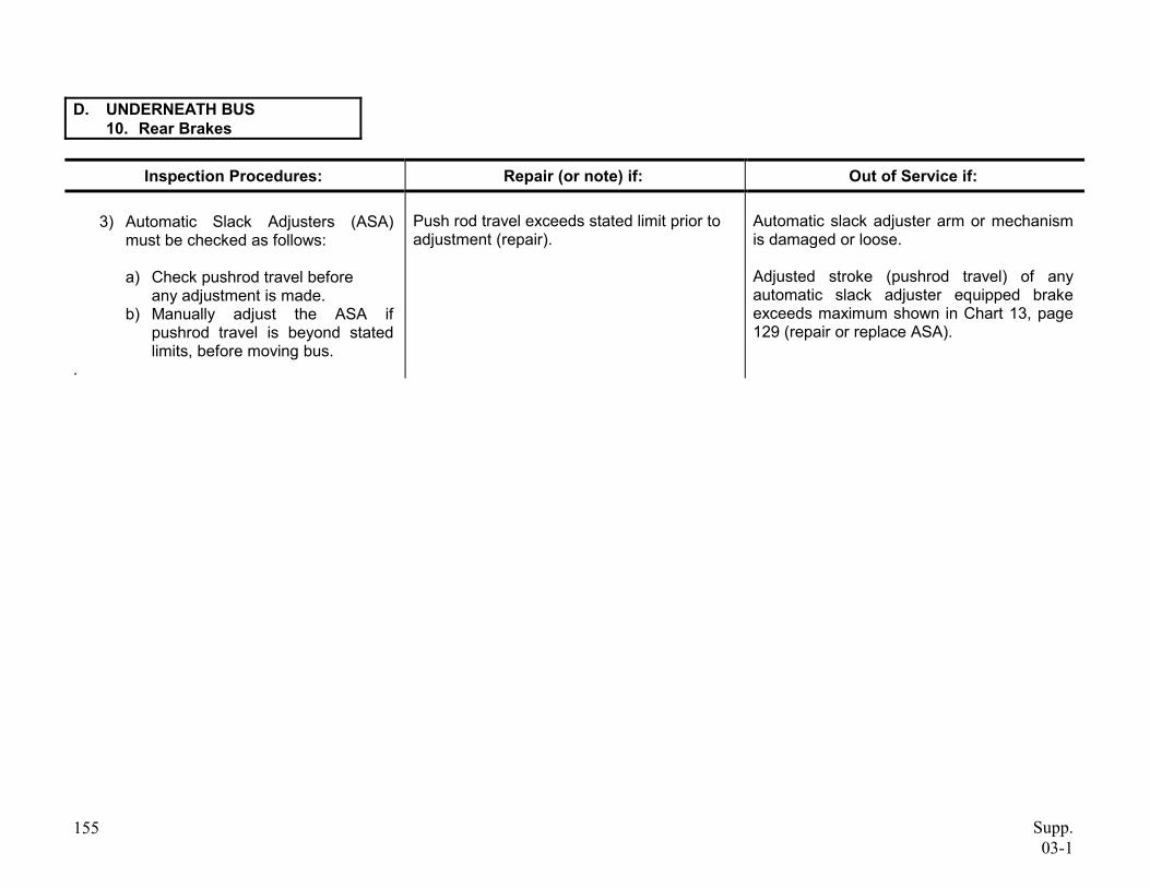
3) Automatic Slack Adjusters (ASA) must be checked as follows:
a) Check pushrod travel before any adjustment is made.
b) Manually adjust the ASA, if pushrod travel is beyond stated limits, before moving bus.
S-cam Bushing Up and Down Play
127
Push rod travel exceeds stated limit prior to adjustment (repair).
Figure 14
Any automatic slack adjuster arm or mechanism is damaged or loose.
Adjusted stroke (pushrod travel) of any automatic slack adjuster equipped brake exceeds maximum shown in Chart 13, page 129.
S-cam In and Out Play
Supp. 03-1
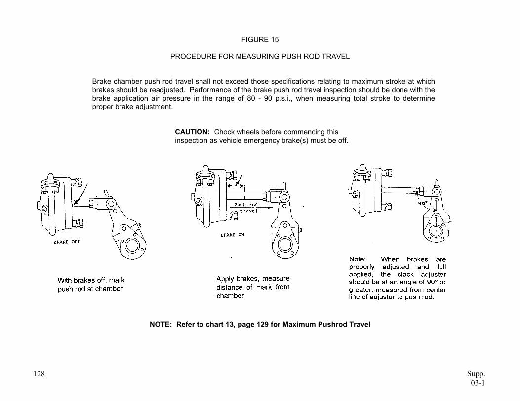
FIGURE 15
PROCEDURE FOR MEASURING PUSH ROD TRAVEL
Brake chamber push rod travel shall not exceed those specifications relating to maximum stroke at which brakes should be readjusted. Performance of the brake push rod travel inspection should be done with the brake application air pressure in the range of 80 - 90 p.s.i., when measuring total stroke to determine proper brake adjustment.
CAUTION: Chock wheels before commencing this inspection as vehicle emergency brake(s) must be off.
NOTE: Refer to chart 13, page 129 for Maximum Pushrod Travel
128 Supp. 03-1
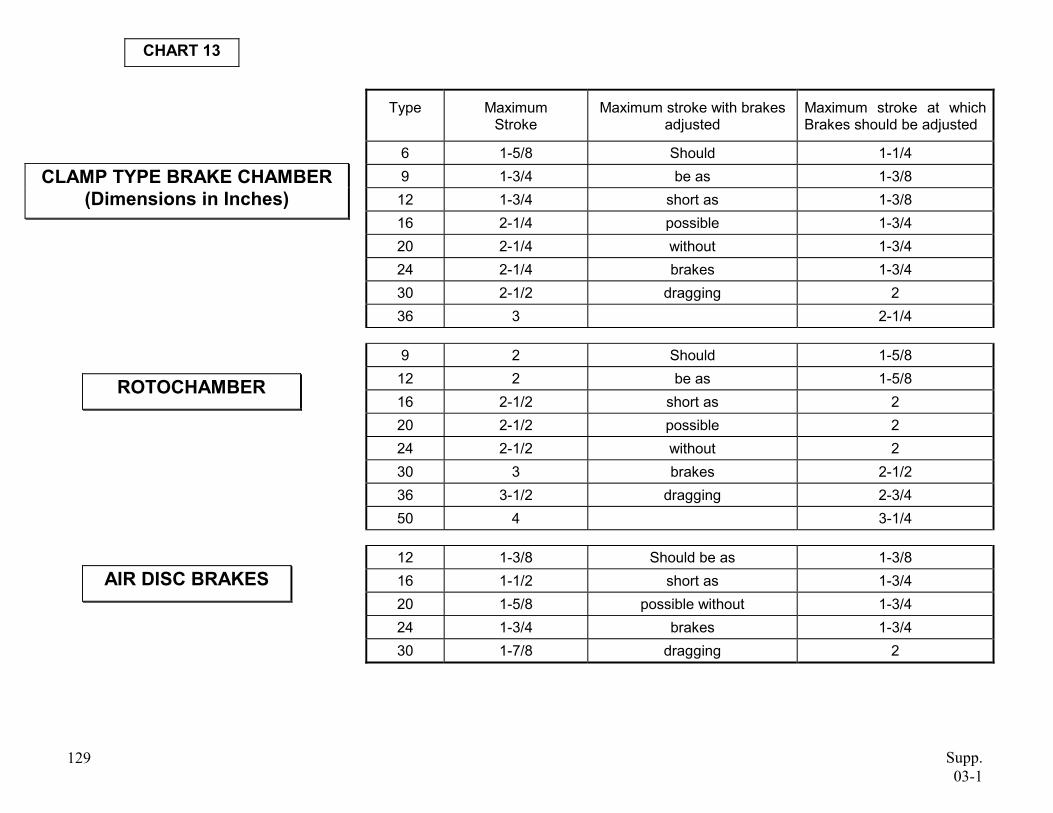
CHART 13
CLAMP TYPE BRAKE CHAMBER(Dimensions in Inches)
ROTOCHAMBER
AIR DISC BRAKES
Type Maximum Stroke
Maximum stroke with brakes adjusted
Maximum stroke at which Brakes should be adjusted
6 1-5/8 Should 1-1/4 9 1-3/4 be as 1-3/8 12 1-3/4 short as 1-3/8 16 2-1/4 possible 1-3/4 20 2-1/4 without 1-3/4 24 2-1/4 brakes 1-3/4 30 2-1/2 dragging 2 36 3 2-1/4
9 2 Should 1-5/8 12 2 be as 1-5/8 16 2-1/2 short as 2 20 2-1/2 possible 2 24 2-1/2 without 2 30 3 brakes 2-1/2 36 3-1/2 dragging 2-3/4 50 4 3-1/4
12 1-3/8 Should be as 1-3/8 16 1-1/2 short as 1-3/4 20 1-5/8 possible without 1-3/4 24 1-3/4 brakes 1-3/4 30 1-7/8 dragging 2
129 Supp.03-1
D. UNDERNEATH BUS 3. Engine/Transmission Mounts, Starter Mounting
Inspection Procedures: Repair (or note) if: Out of Service if:
a. Engine/Transmission Mounts
Inspect engine and transmission mounts for condition and securement.
b. Starter Mounting
Inspect starter for securement and condition. Check for presence of heat shield (if equipped).
130
Heat shield (if equipped) is loose (repair).
Any mounting fasteners are loose, missing, or broken.
Any mount is cracked or has deteriorated rubber.
Any starter mounting bolt, stud, or nut is loose, damaged, broken, or missing.
Starter is damaged or loose.
Heat shield looseness or damage could short positive terminal to ground.
Heat shield (if equipped) is missing or damaged.
Supp. 03-1
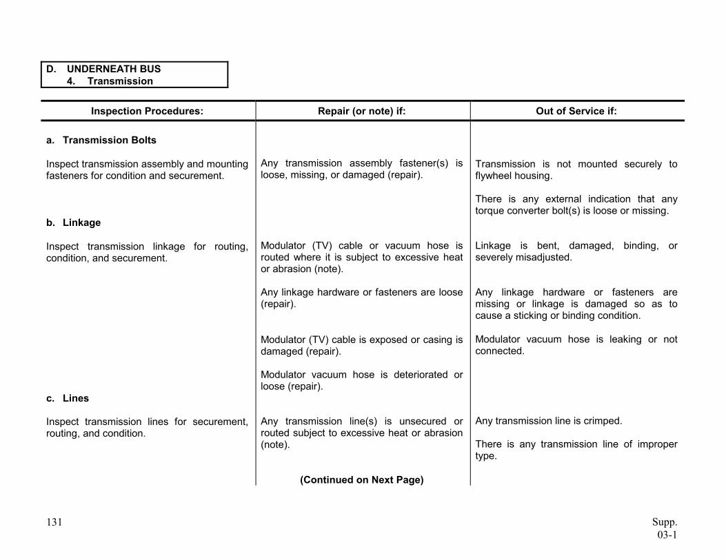
D. UNDERNEATH BUS 4. Transmission
Inspection Procedures: Repair (or note) if: Out of Service if:
a. Transmission Bolts
Inspect transmission assembly and mounting fasteners for condition and securement.
b. Linkage
Inspect transmission linkage for routing, condition, and securement.
c. Lines
Inspect transmission lines for securement, routing, and condition.
131
Any transmission assembly fastener(s) is loose, missing, or damaged (repair).
Modulator (TV) cable or vacuum hose is routed where it is subject to excessive heat or abrasion (note).
Any linkage hardware or fasteners are loose (repair).
Modulator (TV) cable is exposed or casing is damaged (repair).
Modulator vacuum hose is deteriorated or loose (repair).
Any transmission line(s) is unsecured or routed subject to excessive heat or abrasion (note).
(Continued on Next Page)
Transmission is not mounted securely to flywheel housing.
There is any external indication that any torque converter bolt(s) is loose or missing.
Linkage is bent, damaged, binding, or severely misadjusted.
Any linkage hardware or fasteners are missing or linkage is damaged so as to cause a sticking or binding condition.
Modulator vacuum hose is leaking or not connected.
Any transmission line is crimped.
There is any transmission line of improper type.
Supp. 03-1
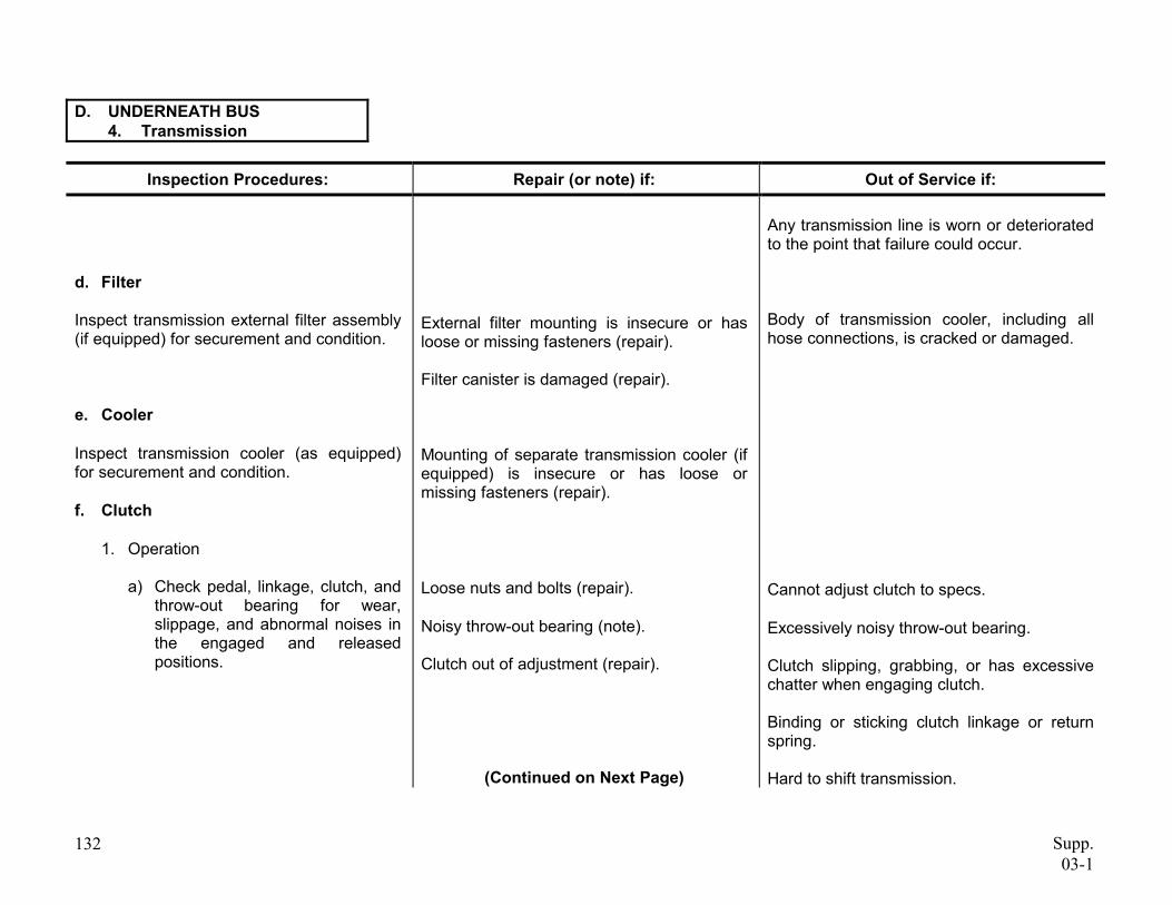
D. UNDERNEATH BUS 4. Transmission
Inspection Procedures: Repair (or note) if: Out of Service if:
d. Filter
Inspect transmission external filter assembly (if equipped) for securement and condition.
e. Cooler
Inspect transmission cooler (as equipped) for securement and condition.
f. Clutch
1. Operation
a) Check pedal, linkage, clutch, and throw-out bearing for wear, slippage, and abnormal noises in the engaged and released positions.
132
External filter mounting is insecure or has loose or missing fasteners (repair).
Filter canister is damaged (repair).
Mounting of separate transmission cooler (if equipped) is insecure or has loose or missing fasteners (repair).
Loose nuts and bolts (repair).
Noisy throw-out bearing (note).
Clutch out of adjustment (repair).
(Continued on Next Page)
Any transmission line is worn or deteriorated to the point that failure could occur.
Body of transmission cooler, including all hose connections, is cracked or damaged.
Cannot adjust clutch to specs.
Excessively noisy throw-out bearing.
Clutch slipping, grabbing, or has excessive chatter when engaging clutch.
Binding or sticking clutch linkage or return spring.
Hard to shift transmission.
Supp. 03-1
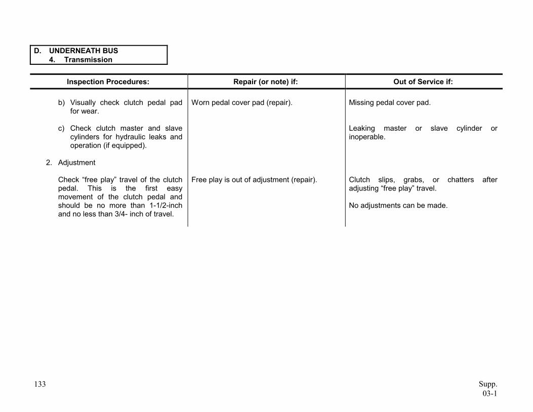
D. UNDERNEATH BUS 4. Transmission
Inspection Procedures: Repair (or note) if: Out of Service if:
b) Visually check clutch pedal pad for wear.
c) Check clutch master and slave cylinders for hydraulic leaks and operation (if equipped).
2. Adjustment
Check “free play” travel of the clutch pedal. This is the first easy movement of the clutch pedal and should be no more than 1-1/2-inch and no less than 3/4- inch of travel.
133
Worn pedal cover pad (repair).
Free play is out of adjustment (repair).
Missing pedal cover pad.
Leaking master or slave cylinder or inoperable.
Clutch slips, grabs, or chatters after adjusting “free play” travel.
No adjustments can be made.
Supp. 03-1
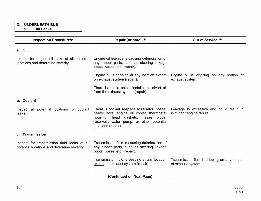
D. UNDERNEATH BUS 5. Fluid Leaks
Inspection Procedures: Repair (or note) if: Out of Service if:
a. Oil
Inspect for engine oil leaks at all potential locations and determine severity.
b. Coolant
Inspect all potential locations for coolant leaks.
c. Transmission
Inspect for transmission fluid leaks at all potential locations and determine severity.
134
Engine oil leakage is causing deterioration of any rubber parts, such as steering linkage boots, hoses, etc. (repair).
Engine oil is dripping at any location except on exhaust system (repair).
There is a drip shield installed to divert oil from the exhaust system (repair).
There is coolant seepage at radiator, hoses, heater core, engine oil cooler, thermostat housing, head gaskets, freeze plugs, reservoir, water pump, or other potential locations (repair).
Transmission fluid is causing deterioration of any rubber parts, such as steering linkage boots, hoses, etc. (repair).
Transmission fluid is seeping at any location except on exhaust system (repair).
(Continued on Next Page)
Engine oil is dripping on any portion of exhaust system.
Leakage is excessive and could result in imminent engine failure.
Transmission fluid is dripping on any portion of exhaust system.
Supp. 03-1
D. UNDERNEATH BUS 5. Fluid Leaks
Inspection Procedures: Repair (or note) if: Out of Service if:
d. Power Steering
Inspect for power steering fluid leaks at all potential locations and determine severity.
135
Power steering fluid is causing deterioration of any rubber parts, such as steering linkage boots, hoses, etc. (repair).
Power steering fluid is seeping (repair). Power steering fluid is dripping.
Power steering reservoir cap or dipstick is missing
Supp. 03-1
D. UNDERNEATH BUS 6. Fuel Tank
Inspection Procedures: Repair (or note) if: Out of Service if:
a. Leaks
Inspect fuel tank assembly for leaks.
b. Mounting
Inspect fuel tank mounting system and barrier (if equipped) for securement and condition.
There is any fuel leakage from the tank, connections, or cap, or cap is missing.
The fuel tank has any cracks.
Any connection(s) are loose at the tank.
Any portion of fuel tank mounting system (including support brackets, retaining straps, and chassis frame) is missing, loose, cracked, or broken.
Any fuel tank mounting fasteners are loose or missing.
Barrier assembly (if originally equipped) is damaged, insecurely mounted, or missing.
(Continued on Next Page)
136 Supp. 03-1
D. UNDERNEATH BUS 6. Fuel Tank
Inspection Procedures: Repair (or note) if: Out of Service if:
c. Hoses
Inspect all fuel lines, hoses, and under-bus fuel system components, for routing, securement, and condition.
d. Wiring
Inspect fuel tank sender unit wiring for securement, routing, and condition.
137
Any wiring or connection has damaged or missing insulation (repair).
Any fuel line or hose is unsecured or is routed subject to excessive heat or abrasion.
Any fuel line or hose is deteriorated or damaged (including cracks or any damage which may cause potential leakage) or clamps are loose or missing.
Any under-bus fuel system filter, water separator, or other components are insecurely mounted, cracked, or damaged.
Any portion of sending unit wiring (including ground) or connections is unsecured or is routed subject to excessive heat or abrasion.
Supp. 03-1
D. UNDERNEATH BUS 7. Brake Equipment
Inspection Procedures: Repair (or note) if: Out of Service if:
a. Brake Lines
Inspect all brake hoses, lines, and connections for routing, securement, and condition.
NOTE: External layer weather cracking only shall not be cause for rejection.
b. Brake Valves
Inspect all brake system valves for securement and condition.
c. Reservoir Mounting
Inspect reservoirs (air vacuum tanks) for securement and condition.
138
Any brake hose or line is unsecured (repair).
(Continued on Next Page)
There is any audible air leak or visible hydraulic brake fluid leakage.
Any brake line or hose is routed subject to excessive heat or abrasion.
Any brake line or hose is deteriorated or damaged to the point that failure could occur (cord frayed, wall thickness thin, rubber contaminated with oil, crimped, etc.).
Any brake line or hose connection is loose.
There are any audible air leaks or visible hydraulic fluid leaks from any brake valve.
Any brake valve is not mounted securely, is cracked, or damaged.
Any reservoir mounting strap or fastener is cracked, loose, or missing.
Supp. 03-1
D. UNDERNEATH BUS 7. Brake Equipment
Inspection Procedures: Repair (or note) if: Out of Service if:
d. Bleed Reservoirs
1) With air system fully charged, check manual operation of safety relief valve.
2) Partially open manual petcock valve on the first (wet) tank.
3) Allow to drain until any moisture (water) or contamination is drained.
139
There is moisture in reservoir (dessicant type air dryer equipped vehicles only; repair).
Safety relief valve leaks or does not release pressure.
There is excessive sludge or oil contamination in the reservoir (more than eight (8) fluid ounces).
Reservoir leaks due to corrosion or is cracked.
Supp. 03-1
D. UNDERNEATH BUS 8. Driveline
Inspection Procedures: Repair (or note) if: Out of Service if:
a. Driveshafts
Inspect driveshafts for condition.
b. U-Joints
Prior to lubrication, inspect U-joints or constant velocity (CV) joints (if equipped) for condition, phasing (alignment of joints), lubrication, and presence of all hardware.
140
Any driveshaft balancing weight (if originally equipped) is missing (repair).
There is any foreign matter wrapped around driveshaft (repair).
U-joints or constant velocity joints are dry of lubrication, or zerk (grease) fitting (if equipped) is missing, clogged, or inaccessible (repair).
(Continued on Next Page)
Any driveshaft is bent or seriously dented.
There are any cracks or other damage in driveshaft, which could cause structural failure.
There are any missing hardware or fasteners in any U-joint or CV joint assembly.
Any U-joint has significant cross-shaft-to-bearing cup play, or CV joint has significant play.
Any U-joint or CV joint shows evidence of significant rusting of bearings.
Any bearing cup is loose in yoke.
Supp. 03-1
D. UNDERNEATH BUS 8. Driveline
Inspection Procedures: Repair (or note) if: Out of Service if:
c. Yokes
Inspect driveshaft yokes for condition and lubrication.
d. Hanger Bearings
Inspect hanger bearings and rubber insulators for condition and securement.
e. Guards
Inspect for presence and condition of driveshaft guards.
141
Driveshaft splines are unlubricated (repair).
Dust cap on yoke is missing (repair).
Zerk (grease) fitting is missing or clogged (repair).
Cork washer in dust cap is missing (note).
Hanger bearing rubber insulator is deteriorated, damaged, or oil soaked (note).
Hanger bearing support is misaligned (repair).
Any driveshaft guard is bent or damaged (repair).
(Continued on Next Page)
Any yoke has significant play in splines.
Any yoke is cracked or damaged.
Bearing outer race is loose in insulator, or inner race is loose on shaft.
There is significant play in hanger bearing.
There is any missing or damaged hardware or fasteners in hanger bearing or support assembly.
Any driveshaft guard is missing, or has loose or damaged mounting fasteners.
Supp. 03-1
D. UNDERNEATH BUS 8. Driveline
Inspection Procedures: Repair (or note) if: Out of Service if:
f. Driveshaft Park Brake
Inspect driveshaft park brake assembly for condition, mounting, securement, and adjustment of linings, drum, linkage, and all other related hardware.
142
Lining is worn down to 2/32-inch from top of rivet head.
Lining is contaminated with grease or oil.
Lining is broken, cracked, or loose.
Drum is cracked or has excessive heat damage or scoring of friction surface.
Any actuating or mounting hardware or fastener is damaged, loose, or missing.
Park brake is not adjusted manufacturer’s specifications.
per
Supp. 03-1
D. UNDERNEATH BUS 9. Rear Suspension
Inspection Procedures: Repair (or note) if: Out of Service if:
a. Axle Housing
Inspect axle housing for condition and leakage.
b. Vent
Inspect condition of axle housing vent.
c. Differential
Inspect differential assembly for condition, lubricant level, and leakage.
143
Vent cap is clogged (repair).
Vent hose (if originally equipped) is cracked, clogged, or missing (repair).
Lubricant level is low (repair).
Differential gaskets or seals are leaking (repair).
(Continued on Next Page)
Any portion of axle housing is cracked or bent.
Any portion of axle housing is leaking lubricant due to cracks, porous metal, or defective weld.
There is any leakage at or around axle housing ends.
Axle vent is not functional or is missing.
There is no lubricant in the differential.
Any external differential hardware or fasteners are loose or missing.
Differential pinion yoke has endplay or sideplay exceeding manufacturer’s specifications.
Pinion/yoke end nut is loose or missing.
Supp. 03-1
D. UNDERNEATH BUS 9. Rear Suspension
Inspection Procedures: Repair (or note) if: Out of Service if:
d. Springs
Inspect rear springs for condition, securement, and alignment.
e. U-Bolts
Inspect spring U-bolts for condition and securement.
144
There are any loose, missing, broken, or worn spring clips (note).
Any leaf spring or air suspension ride height is less than manufacturer’s specifications (repair).
Rubber frame bumper is missing (repair).
Any U-bolt is misaligned (repair).
(Continued on Next Page)
Any leaf spring is broken or missing.
On any air bag type spring assembly, air bag is damaged or leaking, or air lines and valving are damaged or leaking.
Air ride pivot pins and bushings are loose.
There is any misalignment of spring leaves or other evidence that centering pin is loose or broken.
Either rear leaf spring is worn to the point that suspension bottoming has damaged rubber frame bumper.
There is rust underneath U-bolt nuts indicating possibility of looseness.
Any U-bolt, U-bolt seating plate, shock mount bracket, or nut, is loose, missing, cracked, or stripped.
Supp. 03-1
D. UNDERNEATH BUS 9. Rear Suspension
Inspection Procedures: Repair (or note) if: Out of Service if:
f. Shocks
Inspect rear shocks for condition and securement.
g. Shackles
Inspect rear suspension shackles, spring hangers, and hanger pinch bolts for condition and securement.
Any shock is broken.
Any shock fails to function.
Any shock mounting or fastener is loose, missing, cracked, or broken.
There is any wetness around shock body due to leaking shock fluid.
Any rear spring shackle or hanger is cracked or broken.
Any rear spring shackle or hanger is worn to the point, or pinch bolt is stripped or missing, so that spring pin cannot be clamped tightly.
(Continued on Next Page)
145 Supp. 03-1
D. UNDERNEATH BUS 9. Rear Suspension
Inspection Procedures: Repair (or note) if: Out of Service if:
h. Pins and Bushings
Inspect rear spring pins and bushings for wear and lubrication. See Figure 13, page 120, for shackle type system on checking play in pins and bushings. For other types of pin and bushing configurations, see manufacturer’s service manual.
146
Any greaseable spring pin assembly will not accept lubrication, or zerk (grease) fitting is damaged or missing (repair).
(Continued on Next Page)
Inner sleeve on rubber type spring pin assemblies is worn through, or rubber bushing is excessively worn (rubber is compacted or deteriorated resulting in free play between rubber and spring eye or inner sleeve).
Rear spring pin bushing (metal type bushing) is worn through.
Total free play (up and down) of pin and bushing exceeds 1/8-inch for single pin type.
On system using two pins and bushings, combined free play exceeds 1/4-inch.
Supp. 03-1
D. UNDERNEATH BUS 9. Rear Suspension
Inspection Procedures: Repair (or note) if: Out of Service if:
i. Hangers
Inspect hangers for mounting and condition.
j. Seals
Inspect rear wheel seals for condition and leakage.
k. Wheel Bearings
Inspect rear wheel bearings for condition and proper adjustment of bearings.
1) Raise rear wheels (wheels unloaded) and release park brake.
2) Grasp tire and attempt to rock wheel assembly to check for movement.
147
There is wetness or dripping of oil or grease around axle flange (repair).
Any spring hanger or bracket is cracked or broken, or any mounting fastener is loose or missing.
Either rear wheel seal is damaged or leaking excessively.
Any axle flange stud or nut is loose or missing.
There is any detectable looseness or roughness in rear wheel bearings.
Supp. 03-1
D. UNDERNEATH BUS 10. Rear Brakes
Inspection Procedures: Repair (or note) if: Out of Service if:
a. Hoses
Inspect rear brake flexible hoses for condition, securement, and routing.
b. Lines
Inspect air and hydraulic brake lines for routing, securement, and condition.
148
Brake line bracket(s) or securement system is loose or missing (repair).
(Continued on Next Page)
Any rear brake flex hose or connection is leaking fluid or air pressure.
Any rear brake flex hose is kinked, collapsed, bulging, has damaged plies or cord, or is damaged below outer covering.
Any rear brake flex hose supporting brackets are damaged or have loose fasteners.
Any rear brake flex hose is rubbing on or routed against other components.
Any brake line is bent, crimped, or damaged significantly restricting air pressure or hydraulic fluid.
Any brake line or connection is leaking air pressure or hydraulic fluid.
Any brake line is rubbing on other components or is abraded.
Any brake line is not of O.E.M. material, size, or type.
Supp. 03-1
D. UNDERNEATH BUS 10. Rear Brakes
Inspection Procedures: Repair (or note) if: Out of Service if:
c. Chambers
Inspect rear brake chamber assembly or assemblies for securement, condition, and proper size.
d. Slacks
Inspect slack adjusters and S-cam assemblies for wear, condition, operation, and securement.
NOTE: See Section D.2. j., page 126 on brake adjustment, for procedure to check operation of Automatic Slack Adjusters (ASA).
149
Slack adjuster is mounted so that adjuster bolt is facing chamber (repair).
(Continued on Next Page)
Any chamber-mounting bracket is cracked, bent, or broken.
Any rear brake chamber or mounting fastener is damaged or loose.
Either chamber is not original size or size of chamber is not matched (both sides same size).
Any portion of slack adjuster or S-cam is missing, broken, cracked, or badly worn.
S-cam shaft and/or S-cam bushing total wear (up and down) is greater than .040" (see figure 14, page 127).
S-cam in and out end play is more than .060-inch (see figure 14, page 127).
S-cam snap ring is missing.
Slack adjuster has frozen or stripped worm gear or ratchet assembly.
Supp. 03-1
D. UNDERNEATH BUS 10. Rear Brakes
Inspection Procedures: Repair (or note) if: Out of Service if:
e. Pushrods
Inspect pushrod assembly or assemblies for condition, securement, and alignment.
Any portion of pushrod assembly (locknut, pushrod, clevis and pin, or cotter pin) is loose, missing, or damaged.
Pushrod is rubbing against body of chamber, or chamber is misaligned.
Pushrods on left and right sides are not mounted in identical (same) slack adjuster location holes (same effective slack adjuster length).
(Continued on Next Page)
150 Supp. 03-1
D. UNDERNEATH BUS 10. Rear Brakes
Inspection Procedures: Repair (or note) if: Out of Service if:
f. Linings
Inspect linings and foundation brake hardware for contamination, wear, damage, and securement.
151
Lining wear is extremely uneven left and right (repair).
Rear brake lining is less than 5/16-inch thick at center of shoe (on brake blocks with original ¾-inch thickness), (repair).
(Continued on Next Page)
Rear brake lining is less than 1/4-inch thick at center of shoe (on brake blocks with original 3/4 -inch thickness).
Rear brake lining is worn to within 1/16-inch of any rivet or bolt head.
For bonded linings, rear brake lining is worn to within 1/16-inch of shoe table (at center of shoe).
Any foundation brake assembly does not have at least one (1) lining inspection hole.
Lining is broken, cracked, or loose on shoe.
Friction surface is contaminated with oil, grease, or brake fluid.
There is any shimming material between lining and shoe.
Lining is not proper size.
Shoe platform or webbing is cracked or damaged.
There is any loose, damaged, or missing foundation brake hardware within the drum.
Supp. 03-1
D. UNDERNEATH BUS 10. Rear Brakes
Inspection Procedures: Repair (or note) if: Out of Service if:
g. Drums
Inspect rear brake drum(s) for condition and oversize.
There is any crack (other than heat checks) in drum.
There is more than .060-inch wear in drum friction surface (inside diameter is more than .120-inch over original).
There is any grease, oil, or brake fluid on inside of drum.
Drum is not mounted securely to hub, or fasteners are loose.
Drum is not centered on hub (if equipped) causing more than .010-inch out of round.
(Continued on Next Page)
152 Supp. 03-1
D. UNDERNEATH BUS 10. Rear Brakes
Inspection Procedures: Repair (or note) if: Out of Service if:
h. Rotors
Inspect rear brake rotor(s) for mounting, thickness, and condition.
i. Wheel Cylinders or Calipers
Inspect wheel cylinder(s) or caliper(s) for leaks, mounting, and condition.
153
Any wheel cylinder or caliper dust boot is damaged or missing (repair).
(Continued on Next Page)
Rotor mounting is not secure.
Rotor has excessive runout (beyond manufacturer’s specifications) causing a pulsating in brake pedal.
Rotor has cracks (other than heat checks) or other mechanical defects.
Friction surface is contaminated with oil, grease, or brake fluid.
Rotor thickness is less than manufacturer’s specifications stamped on rotor.
Any rotor friction surface is significantly grooved or damaged.
Any wheel cylinder or caliper is not securely mounted or has loose or missing fasteners.
Any wheel cylinder or caliper is leaking.
There is uneven lining or pad wear, rotor or drum damage, evidence of dragging, or other evidence that any wheel cylinder or caliper may be sticking.
Supp. 03-1
D. UNDERNEATH BUS 10. Rear Brakes
Inspection Procedures: Repair (or note) if: Out of Service if:
j. Adjust Brakes
1) For air wedge brakes and hydraulic drum brakes, adjust rear brakes at every monthly inspection as follows:
a) Brakes must be adjusted until brake drum does not turn.
b) Back off brake adjustment until there is slight drag on drum surface (.020" clearance between lining and drum.
2) For S-cam and air disc brakes at every monthly inspection, brake chamber pushrod travel must be checked (see figure 15, page 128) at all four (4) wheel positions. Brakes must be adjusted as necessary to achieve less than or equal to the maximum pushrod travel (after adjustment) shown in Chart 13, page 129.
There is any damage or condition, which prevents proper adjustment of brakes.
There is any damage or condition, which prevents proper adjustment of brakes.
(Continued on Next Page)
154 Supp. 03-1
D. UNDERNEATH BUS 10. Rear Brakes
Inspection Procedures: Repair (or note) if: Out of Service if:
3) Automatic Slack Adjusters (ASA) must be checked as follows:
a) Check pushrod travel before any adjustment is made.
b) Manually adjust the ASA if pushrod travel is beyond stated limits, before moving bus.
.
155
Push rod travel exceeds stated limit prior to adjustment (repair).
Automatic slack adjuster arm or mechanism is damaged or loose.
Adjusted stroke (pushrod travel) of any automatic slack adjuster equipped brake exceeds maximum shown in Chart 13, page 129 (repair or replace ASA).
Supp. 03-1
D. UNDERNEATH BUS 11. Body Securement and Structure
Inspection Procedures: Repair (or note) if: Out of Service if:
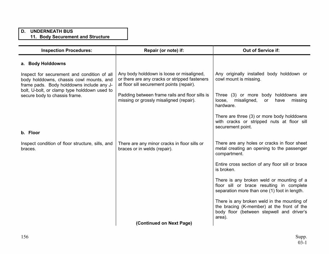
a. Body Holddowns
Inspect for securement and condition of all body holddowns, chassis cowl mounts, and frame pads. Body holddowns include any J-bolt, U-bolt, or clamp type holddown used to secure body to chassis frame.
b. Floor
Inspect condition of floor structure, sills, and braces.
156
Any body holddown is loose or misaligned, or there are any cracks or stripped fasteners at floor sill securement points (repair).
Padding between frame rails and floor sills is missing or grossly misaligned (repair).
There are any minor cracks in floor sills or braces or in welds (repair).
(Continued on Next Page)
Any originally installed body holddown or cowl mount is missing.
Three (3) or more body holddowns are loose, misaligned, or have missing hardware.
There are three (3) or more body holddowns with cracks or stripped nuts at floor sill securement point.
There are any holes or cracks in floor sheet metal creating an opening to the passenger compartment.
Entire cross section of any floor sill or brace is broken.
There is any broken weld or mounting of a floor sill or brace resulting in complete separation more than one (1) foot in length.
There is any broken weld in the mounting of the bracing (K-member) at the front of the body floor (between stepwell and driver’s area).
Supp. 03-1
D. UNDERNEATH BUS 11. Body Securement and Structure
Inspection Procedures: Repair (or note) if: Out of Service if:
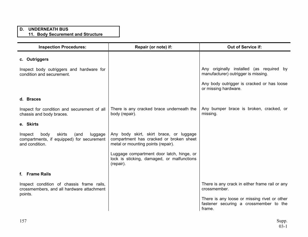
c. Outriggers
Inspect body outriggers and hardware for condition and securement.
d. Braces
Inspect for condition and securement of all chassis and body braces.
e. Skirts
Inspect body skirts (and luggage compartments, if equipped) for securement and condition.
f. Frame Rails
Inspect condition of chassis frame rails, crossmembers, and all hardware attachment points.
157
There is any cracked brace underneath the body (repair).
Any body skirt, skirt brace, or luggage compartment has cracked or broken sheet metal or mounting points (repair).
Luggage compartment door latch, hinge, or lock is sticking, damaged, or malfunctions (repair).
Any originally installed (as required by manufacturer) outrigger is missing.
Any body outrigger is cracked or has loose or missing hardware.
Any bumper brace is broken, cracked, or missing.
There is any crack in either frame rail or any crossmember.
There is any loose or missing rivet or other fastener securing a crossmember to the frame.
Supp. 03-1
D. UNDERNEATH BUS 12. Exhaust Systems
Inspection Procedures: Repair (or note) if: Out of Service if:
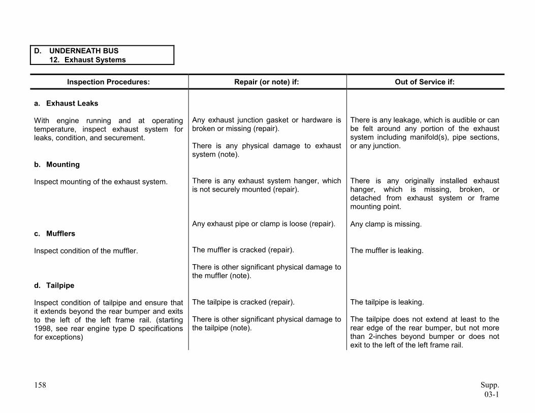
a. Exhaust Leaks
With engine running and at operating temperature, inspect exhaust system for leaks, condition, and securement.
b. Mounting
Inspect mounting of the exhaust system.
c. Mufflers
Inspect condition of the muffler.
d. Tailpipe
Inspect condition of tailpipe and ensure that it extends beyond the rear bumper and exits to the left of the left frame rail. (starting 1998, see rear engine type D specifications for exceptions)
158
Any exhaust junction gasket or hardware is broken or missing (repair).
There is any physical damage to exhaust system (note).
There is any exhaust system hanger, which is not securely mounted (repair).
Any exhaust pipe or clamp is loose (repair).
The muffler is cracked (repair).
There is other significant physical damage to the muffler (note).
The tailpipe is cracked (repair).
There is other significant physical damage to the tailpipe (note).
There is any leakage, which is audible or can be felt around any portion of the exhaust system including manifold(s), pipe sections, or any junction.
There is any originally installed exhaust hanger, which is missing, broken, or detached from exhaust system or frame mounting point.
Any clamp is missing.
The muffler is leaking.
The tailpipe is leaking.
The tailpipe does not extend at least to the rear edge of the rear bumper, but not more than 2-inches beyond bumper or does not exit to the left of the left frame rail.
Supp. 03-1
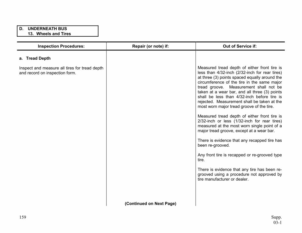
D. UNDERNEATH BUS 13. Wheels and Tires
Inspection Procedures: Repair (or note) if: Out of Service if:
a. Tread Depth
Inspect and measure all tires for tread depth and record on inspection form.
Measured tread depth of either front tire is less than 4/32-inch (2/32-inch for rear tires) at three (3) points spaced equally around the circumference of the tire in the same major tread groove. Measurement shall not be taken at a wear bar, and all three (3) points shall be less than 4/32-inch before tire is rejected. Measurement shall be taken at the most worn major tread groove of the tire.
Measured tread depth of either front tire is 2/32-inch or less (1/32-inch for rear tires) measured at the most worn single point of a major tread groove, except at a wear bar.
There is evidence that any recapped tire has been re-grooved.
Any front tire is recapped or re-grooved type tire.
There is evidence that any tire has been re-grooved using a procedure not approved by tire manufacturer or dealer.
(Continued on Next Page)
159 Supp. 03-1
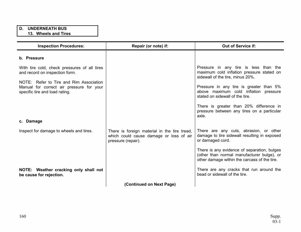
D. UNDERNEATH BUS 13. Wheels and Tires
Inspection Procedures: Repair (or note) if: Out of Service if:
b. Pressure
With tire cold, check pressures of all tires and record on inspection form.
NOTE: Refer to Tire and Rim Association Manual for correct air pressure for your specific tire and load rating.
c. Damage
Inspect for damage to wheels and tires.
Pressure in any tire is less than the maximum cold inflation pressure stated on sidewall of the tire, minus 20%.
Pressure in any tire is greater than 5% above maximum cold inflation pressure stated on sidewall of the tire.
There is greater than 20% difference in pressure between any tires on a particular axle.
There are any cuts, abrasion, or other damage to tire sidewall resulting in exposed or damaged cord.
There is any evidence of separation, bulges (other than normal manufacturer bulge), or other damage within the carcass of the tire.
There are any cracks that run around the bead or sidewall of the tire.
Supp. 03-1
There is foreign material in the tire tread, which could cause damage or loss of air pressure (repair).
NOTE: Weather cracking only shall not be cause for rejection.
(Continued on Next Page)
160
D. UNDERNEATH BUS 13. Wheels and Tires
Inspection Procedures: Repair (or note) if: Out of Service if:
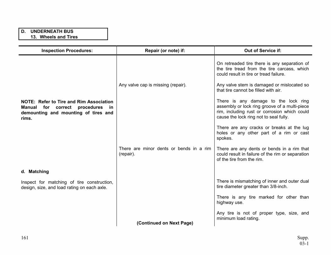
NOTE: Refer to Tire and Rim Association Manual for correct procedures in demounting and mounting of tires and rims.
d. Matching
Inspect for matching of tire construction, design, size, and load rating on each axle.
161
Any valve cap is missing (repair).
There are minor dents or bends in a rim (repair).
(Continued on Next Page)
On retreaded tire there is any separation of the tire tread from the tire carcass, which could result in tire or tread failure.
Any valve stem is damaged or mislocated so that tire cannot be filled with air.
There is any damage to the lock ring assembly or lock ring groove of a multi-piece rim, including rust or corrosion which could cause the lock ring not to seal fully.
There are any cracks or breaks at the lug holes or any other part of a rim or cast spokes.
There are any dents or bends in a rim that could result in failure of the rim or separation of the tire from the rim.
There is mismatching of inner and outer dual tire diameter greater than 3/8-inch.
There is any tire marked for other than highway use.
Any tire is not of proper type, size, and minimum load rating.
Supp. 03-1
D. UNDERNEATH BUS 13. Wheels and Tires
Inspection Procedures: Repair (or note) if: Out of Service if:
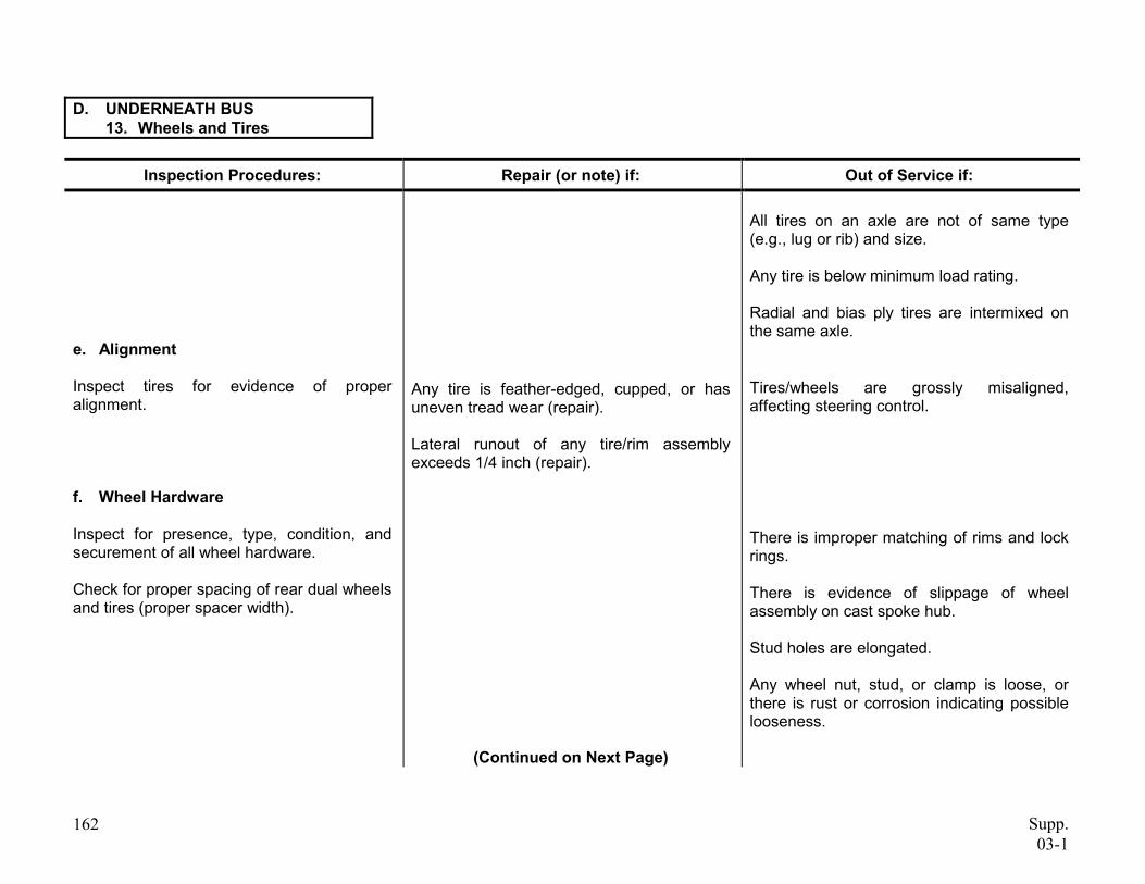
e. Alignment
Inspect tires for evidence of proper alignment.
f. Wheel Hardware
Inspect for presence, type, condition, and securement of all wheel hardware.
Check for proper spacing of rear dual wheels and tires (proper spacer width).
162
Any tire is feather-edged, cupped, or has uneven tread wear (repair).
Lateral runout of any tire/rim assembly exceeds 1/4 inch (repair).
(Continued on Next Page)
All tires on an axle are not of same type (e.g., lug or rib) and size.
Any tire is below minimum load rating.
Radial and bias ply tires are intermixed on the same axle.
Tires/wheels are grossly misaligned, affecting steering control.
There is improper matching of rims and lock rings.
There is evidence of slippage of wheel assembly on cast spoke hub.
Stud holes are elongated.
Any wheel nut, stud, or clamp is loose, or there is rust or corrosion indicating possible looseness.
Supp. 03-1
D. UNDERNEATH BUS 13. Wheels and Tires
Inspection Procedures: Repair (or note) if: Out of Service if:
Inspect for correct wheel color. Stud piloted and spoke wheels are to be painted black. Hub piloted wheels are to be painted National School Bus Yellow.
Inspect for correct wheel type.
163
Any wheel, nut, stud, or clamp is broken or missing.
Any improper spacer is installed between dual wheels.
Any bus built since October 1987, is not equipped with disc type (Budd) wheel.
Wheel(s) not painted the correct color.
Stud piloted wheel is installed on a hub piloted axle or hub.
Supp. 03-1
THIS PAGE INTENTIONALLY LEFT BLANK
164 Supp.03-1