D S ATION U S N N I P F I E O T DFI T DEEP FOUNDATIONS ... · Suape in Ipojuca, in the northeastern...
6
DFI I O T N A S D I N N S U T O I F T U P E T E E D DEEP FOUNDATIONS The Magazine of the Deep Foundations Institute Fall 2010 Brazil’s Megaproject Shipyard Winner of the 2010 Outstanding Project of the Year
Transcript of D S ATION U S N N I P F I E O T DFI T DEEP FOUNDATIONS ... · Suape in Ipojuca, in the northeastern...
DFIIOT NA SD INN
SU TO IF T
UPE T
E E
D DEEP FOUNDATIONSThe Magazine of the Deep Foundations InstituteFall 2010
Brazil’s Megaproject ShipyardWinner of the 2010 Outstanding Project of the Year

8 • DEEP FOUNDATIONS • FALL 2010
All these works presented geotechnical challenges.
The ground profile across the site was generally made up of
loose granular fill material overlying sandy silt/silty sand that in
turn, was underlain by claystone and sandstone at approximately
25-35 m (82-115 ft) below ground level. The layer of silty sand
directly below the fill was either dense to very dense or, in places,
weak sandstone up to 6 m (20 ft) thick. This weak rock layer was
clearly not formed by normal sedimentary rock processes and
appeared to be a natural cementation of the sand grains as a
consequence of the lixiviation (leaching) of the acids from
decomposition of organic materials giving the sandy soil the brown
color. The material below this sandstone layer was generally a
medium dense state, varying from sands to clayey sandy silts. In
some localized areas the sandy silt/silty sand directly above the
deep sandstone was replaced by soft to firm silty clays up to 13 m
(43 ft) thick. These soft clays are believed to be the location of an
old river channel. The site has high ground water relating closely to
sea level that indicated the generally high permeability of the soils.
The main design and construction challenges at Suape were:
• Construction through and/or excavation of an upper sandstone
layer that required mobilizing the correct equipment during
construction, clearly identified in the design package.
• The presence of soft clay at depth meant there was little passive
support for the wall below floor level during temporary stages
of construction. Considering that the dry dock (once the dock
floor was in place) would support the upper wall, the wall
below the floor had to function as a cut-off wall to reduce the
volume of water flowing into the drainage system and
underside of the dock floor. It was important to consider that
the wall was also designed to resist the vertical loads from the
big Goliath cranes (up to 15,000 kN) running on it.
• The quay wall depth had to be increased after its construction as
a consequence of the changes in the dredge level imposed by
Port Authorities of Suape.
The initial basic design concept for the 400 m (1,312 ft) long x 76 m
(250 ft) wide x 14 m (46 ft) deep dry dock wall was to use steel sheet
piling. Because of the erratic soil profile, the client decided to make
a preliminary test on the drivability of the sheet piles to check the
Principal Challenges
efficacy of the solution. These tests proved that the energy needed
to drive the sheet piles was so large, due to the presence of a
sandstone layer between layers of sand and clay, that it would be
necessary to drill a pre-hole with an auger to avoid significant
deformations. This drilling would have increased the cost and time
schedule with no guarantee of success.
The final design concept was to use a diaphragm wall without
tiebacks. Due to the great bending moments involved, a T-shape 60
cm (2 ft) thick wall was designed with support at the top and one at
the bottom (counterfort wall).
The depth of the T-shape diaphragm wall ranged between 18 m
(59 ft) and 30 m (98 ft), always reaching bedrock. The large
difference in depth was due to a layer of soft clay created by what
was likely an old river channel.
The diaphragm was installed by a clam-shell 3.20 m (10.5 ft)
long x 0.60 m (2 ft) wide mounted in crawler cranes of 70 t. Crawler
cranes up to 100 t were used to place the reinforcement cage. The
estimated volume of each T-panel was approximately 100 m3
(3,531 cu ft). The basic concept of the dry dock floor design included:
• A sub-floor drainage system to prevent the buildup of hydro-
static pressure; the water reaching this drainage system had to be
pumped away to the sea continuously to keep the dock dry.
• A pressure relief system so that the floor would neither lift nor
suffer damage in the event of pressure build up due to the
malfunction of the drainage system.
• Consideration of the heavy loads involved when the dock was
either flooded or when the mega blocks were being assembled
over the floor slab with the dock when dry.
The foundation solution for the floor was bored piles drilled with ben-
tonite slurry, 0.9 m (2.95 ft) diameter for a service load of 5,000 kN.
The design criteria indicated that piles be bored to bedrock. In
the dry dock area, the depths ranged between 10 m (33 ft) to 20 m
(66 ft) below the floor slab level. The significant difference in the bed-
rock level was very similar both in terms of depths and charac-
teristics to what was detected in the diaphragm wall perimeter.
Because of the great difference in the depth of the piles,
Brasfond proposed to undertake three static pile load tests in areas
where the bedrock level was different to confirm the service loads
being adopted. The client accepted.
DEEP FOUNDATIONS • FALL 2010 • 9
of 1,500 kN each, with four additional support cranes, two of
which have a capacity of 500 kN and two with 350 kN.
The south outfitting quay is 730 m (2,400 ft) long and is served
by another two 35 t cranes. The north quay, which extends 680 m
(2,230 ft), is used for construction and repair of offshore platforms.
The scale of such a manufacturing facility places the shipyard in
the top group of fourth-generation shipyards with Asian plants,
now at the forefront of the worldwide shipbuilding industry.
Atlântico Sul Shipyard is in the Industrial Port Complex of
Suape in Ipojuca, in the northeastern state of Pernambuco. The
Complex of Suape connects to main navigation routes and to 160
ports worldwide. Its location is advantageous in relation to the big
oil and natural gas production regions, such as the Brazilian Tupi oil
field, Gulf of Mexico and Coast of West Africa.
Brasfond’s contract included the foundations and retaining walls
for the following structures:
• The retaining wall of a de-waterable dry dock.
• A large expanse of quay wall plus cranage to provide a deep
berth for merchant ships.
• All ancillary support facilities and administrative buildings.
• The mega block areas. This term refers to construction method-
ology in which eight large sections of ships are welded together
inside the dock thus reducing overall construction time.
Brasfond Contract
Atlântico Sul Shipyard was established in November 2005 through
a partnership between Camargo Corrêa, Queiroz Galvão, Samsung
Heavy Industries from South Korea and PJMR, an equity holding
and ventures management company in the shipbuilding and
offshore sector.
The partnership’s goal was to be the biggest and most modern
naval and offshore construction and repair shipyard in the southern
hemisphere. This undertaking was a landmark in the revitalization
of the Brazilian shipbuilding industry, with an approximate
investment of $1billion (U.S.).
The shipyard manufactures carrier vessels up to 500,000 DWT,
as well as offshore platforms of the semi-submersible type, FPSO
(Floating Production, Storage and Off-loading), and tension-leg
platforms, among others. It also offers a vast range of repair services
for vessels and oil exploration units, taking advantage of the
shipyard’s strategic loca-
tion in relation to both
the global maritime
trade and the large deep-
water oil and gas pro-
duction fields.
The shipyard can process 160,000 mt (180,000 U.S. short tons)
of steel per year, in an area of 1,620,000 sq m (17,400,000 sq ft), from
which 130,000 sq m (1,400,000 sq ft) are covered areas used to
process, cut and paint the steel. The area also contains a dry dock
that is 400 m (1,312 ft) long and 76 m (250 ft) wide and 14 m (46 ft)
deep. The dry dock is served by two Goliath Cranes with capacities
Atlântico Sul Shipyard: Outstanding Project Award Winner
Aerial view of the Atlântico Sul megaproject
AUTHOR:Armando CaputoTechnical Director, Grupo Brasfond
Figure 2: Typical soil profile
Figure 1: Overview of Brasfond’s works

8 • DEEP FOUNDATIONS • FALL 2010
All these works presented geotechnical challenges.
The ground profile across the site was generally made up of
loose granular fill material overlying sandy silt/silty sand that in
turn, was underlain by claystone and sandstone at approximately
25-35 m (82-115 ft) below ground level. The layer of silty sand
directly below the fill was either dense to very dense or, in places,
weak sandstone up to 6 m (20 ft) thick. This weak rock layer was
clearly not formed by normal sedimentary rock processes and
appeared to be a natural cementation of the sand grains as a
consequence of the lixiviation (leaching) of the acids from
decomposition of organic materials giving the sandy soil the brown
color. The material below this sandstone layer was generally a
medium dense state, varying from sands to clayey sandy silts. In
some localized areas the sandy silt/silty sand directly above the
deep sandstone was replaced by soft to firm silty clays up to 13 m
(43 ft) thick. These soft clays are believed to be the location of an
old river channel. The site has high ground water relating closely to
sea level that indicated the generally high permeability of the soils.
The main design and construction challenges at Suape were:
• Construction through and/or excavation of an upper sandstone
layer that required mobilizing the correct equipment during
construction, clearly identified in the design package.
• The presence of soft clay at depth meant there was little passive
support for the wall below floor level during temporary stages
of construction. Considering that the dry dock (once the dock
floor was in place) would support the upper wall, the wall
below the floor had to function as a cut-off wall to reduce the
volume of water flowing into the drainage system and
underside of the dock floor. It was important to consider that
the wall was also designed to resist the vertical loads from the
big Goliath cranes (up to 15,000 kN) running on it.
• The quay wall depth had to be increased after its construction as
a consequence of the changes in the dredge level imposed by
Port Authorities of Suape.
The initial basic design concept for the 400 m (1,312 ft) long x 76 m
(250 ft) wide x 14 m (46 ft) deep dry dock wall was to use steel sheet
piling. Because of the erratic soil profile, the client decided to make
a preliminary test on the drivability of the sheet piles to check the
Principal Challenges
efficacy of the solution. These tests proved that the energy needed
to drive the sheet piles was so large, due to the presence of a
sandstone layer between layers of sand and clay, that it would be
necessary to drill a pre-hole with an auger to avoid significant
deformations. This drilling would have increased the cost and time
schedule with no guarantee of success.
The final design concept was to use a diaphragm wall without
tiebacks. Due to the great bending moments involved, a T-shape 60
cm (2 ft) thick wall was designed with support at the top and one at
the bottom (counterfort wall).
The depth of the T-shape diaphragm wall ranged between 18 m
(59 ft) and 30 m (98 ft), always reaching bedrock. The large
difference in depth was due to a layer of soft clay created by what
was likely an old river channel.
The diaphragm was installed by a clam-shell 3.20 m (10.5 ft)
long x 0.60 m (2 ft) wide mounted in crawler cranes of 70 t. Crawler
cranes up to 100 t were used to place the reinforcement cage. The 3estimated volume of each T-panel was approximately 100 m
(3,531 cu ft). The basic concept of the dry dock floor design included:
• A sub-floor drainage system to prevent the buildup of hydro-
static pressure; the water reaching this drainage system had to be
pumped away to the sea continuously to keep the dock dry.
• A pressure relief system so that the floor would neither lift nor
suffer damage in the event of pressure build up due to the
malfunction of the drainage system.
• Consideration of the heavy loads involved when the dock was
either flooded or when the mega blocks were being assembled
over the floor slab with the dock when dry.
The foundation solution for the floor was bored piles drilled with ben-
tonite slurry, 0.9 m (2.95 ft) diameter for a service load of 5,000 kN.
The design criteria indicated that piles be bored to bedrock. In
the dry dock area, the depths ranged between 10 m (33 ft) to 20 m
(66 ft) below the floor slab level. The significant difference in the bed-
rock level was very similar both in terms of depths and charac-
teristics to what was detected in the diaphragm wall perimeter.
Because of the great difference in the depth of the piles,
Brasfond proposed to undertake three static pile load tests in areas
where the bedrock level was different to confirm the service loads
being adopted. The client accepted.
DEEP FOUNDATIONS • FALL 2010 • 9
of 1,500 kN each, with four additional support cranes, two of
which have a capacity of 500 kN and two with 350 kN.
The south outfitting quay is 730 m (2,400 ft) long and is served
by another two 35 t cranes. The north quay, which extends 680 m
(2,230 ft), is used for construction and repair of offshore platforms.
The scale of such a manufacturing facility places the shipyard in
the top group of fourth-generation shipyards with Asian plants,
now at the forefront of the worldwide shipbuilding industry.
Atlântico Sul Shipyard is in the Industrial Port Complex of
Suape in Ipojuca, in the northeastern state of Pernambuco. The
Complex of Suape connects to main navigation routes and to 160
ports worldwide. Its location is advantageous in relation to the big
oil and natural gas production regions, such as the Brazilian Tupi oil
field, Gulf of Mexico and Coast of West Africa.
Brasfond’s contract included the foundations and retaining walls
for the following structures:
• The retaining wall of a de-waterable dry dock.
• A large expanse of quay wall plus cranage to provide a deep
berth for merchant ships.
• All ancillary support facilities and administrative buildings.
• The mega block areas. This term refers to construction method-
ology in which eight large sections of ships are welded together
inside the dock thus reducing overall construction time.
Brasfond Contract
Atlântico Sul Shipyard was established in November 2005 through
a partnership between Camargo Corrêa, Queiroz Galvão, Samsung
Heavy Industries from South Korea and PJMR, an equity holding
and ventures management company in the shipbuilding and
offshore sector.
The partnership’s goal was to be the biggest and most modern
naval and offshore construction and repair shipyard in the southern
hemisphere. This undertaking was a landmark in the revitalization
of the Brazilian shipbuilding industry, with an approximate
investment of $1billion (U.S.).
The shipyard manufactures carrier vessels up to 500,000 DWT,
as well as offshore platforms of the semi-submersible type, FPSO
(Floating Production, Storage and Off-loading), and tension-leg
platforms, among others. It also offers a vast range of repair services
for vessels and oil exploration units, taking advantage of the
shipyard’s strategic loca-
tion in relation to both
the global maritime
trade and the large deep-
water oil and gas pro-
duction fields.
The shipyard can process 160,000 mt (180,000 U.S. short tons)
of steel per year, in an area of 1,620,000 sq m (17,400,000 sq ft), from
which 130,000 sq m (1,400,000 sq ft) are covered areas used to
process, cut and paint the steel. The area also contains a dry dock
that is 400 m (1,312 ft) long and 76 m (250 ft) wide and 14 m (46 ft)
deep. The dry dock is served by two Goliath Cranes with capacities
Atlântico Sul Shipyard: Outstanding Project Award Winner
Aerial view of the Atlântico Sul megaproject
AUTHOR:Armando CaputoTechnical Director, Grupo Brasfond
Figure 2: Typical soil profile
Figure 1: Overview of Brasfond’s works
DEEP FOUNDATIONS • FALL 2010 • 1110 • DEEP FOUNDATIONS • FALL 2010
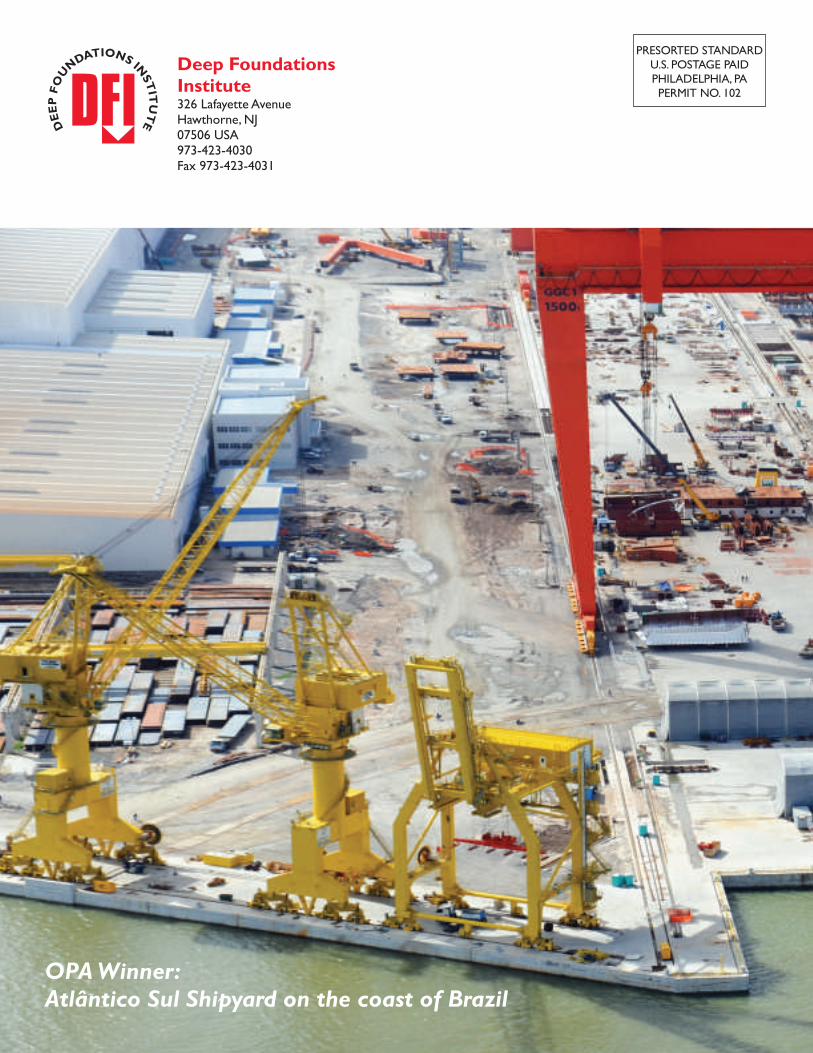
The final decision was to use a diaphragm wall, with depths
ranging between 22 m (72 ft) up to 30 m (98 ft), tied with a group of
inclined root piles to resist the bending moment (pile trestle) and
bored piles to take vertical loads, as shown below.
The assumption was that the dredging in front of the quay
would be carried out after constructing the quay structure, and the
proposed dredged depth was -12 m (39 ft).
When the diaphragm wall was completed, the Port Authorities
decided that the dredged depth had to be increased to -15 m (49 ft).
After analyzing the impact carefully, the designers thought it
necessary to increase the depth of the diaphragm wall. Because it
was already constructed, the solution was to create a spaced curtain
(non-tangent/non-overlapping) of bored piles as close as possible
to the wall to resist the bending moment induced by the new
dredged depth, as shown below.
Inclinometers and strain-gauges were installed in the wall and it
was closely monitored during dredging.
This area surrounding the dry dock was designed to resist the
weight of the mega blocks constructed to facilitate ship assembly.
The large steel blocks are built outside the dry dock in giant pieces
and moved into the dry dock by the Goliath cranes. This procedure
Mega Block Area and Ancillary Facilities
minimizes the construction time for ships inside the dock and, in
turn, maximizes ship production. The basic concept of the design
was a slab with piles. Due to the heterogeneous soil condition in the
area, the designer sometimes used bored piles and in other cases
Continuous Flight Auger (CFA) piles.
Initially, the client thought of installing pre-cast piles for these
foundations, and again we conducted a drivability test. The results
turned out to be negative, due to a dense upper sand layer that
broke the pre-cast elements when they were driven into ground.
Once more, it seemed necessary to pre-hole in order to install these.
We tested an alternative solution, CFA piles, conducting several
static load tests with excellent results. We tested an alternative
solution, CFA piles. Consequently, the general solution was CFA
piles except in areas where we found the deeper soft clay layer. In
these areas, the designer used root piles, 0.4 m (1.3 ft) and 0.5 m
(1.6 ft) in diameter, up to 30 m (98 ft) long.
Some lessons learned from this project were:
• It was extremely important that the client, the designer and the
foundation contractor interacted to find the best solution,
quickly and inside the clients’ budget.
• Due to a good soil investigation and the close monitoring
during the execution, we overcame all the underground
challenges, minimizing overall construction risks.
• The foundation design was optimized as a consequence of the
static load tests that were conducted before the start of the job.
• Due to the short time available to fulfill the contracts for ship
assembly, construction of the shipyard was concurrent with the
construction of the first ship. This is clearly reflected in the total
time taken to complete the foundations of the shipyard, 24 months,
in comparison to the completion of the first ship, 32 months.
ConclusionConstruction underway for the dock floor
Figures 6: Quay platform after increasing depth
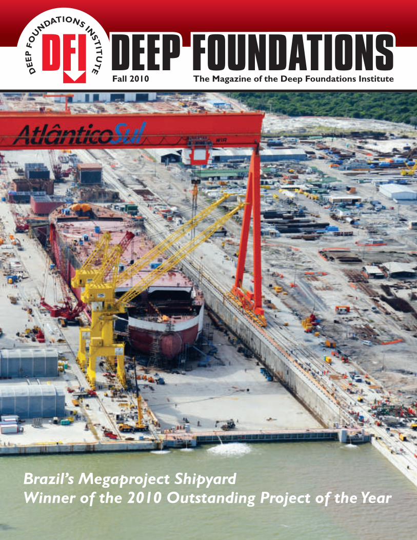
To save time, all the piles below the slab were installed before the
dry dock excavation, so it was very important to be sure that the pile
cut-off level was preserved and the reinforcement cage was placed in
the right position. The piles were installed by hydraulic rigs up to
260 kNm torque with verticality and depth monitoring systems.
The Overview of the dry dock (Figure 3) shows a general view
and a cross section of the dry dock as well as the mega block paved
area below. Another important part of the dry dock work was the
excavation to concrete the floor slab.
This work was done in steps as follows:
a) Concreting the reinforcement beam over the diaphragm wall
and the mega block paved area
b) Excavating the dry dock up to 3 m (10 ft) below ground level
c) Installing the dewatering system inside and outside the dock area
d) Excavation of the soil in the central part of the floor up to the
final level leaving a berm along the wall
e) Cutting off the pile heads, installing the drainage system,
placing the reinforcement steel and concreting the central part
of the floor slab, repeated until the floor slab was complete
f) After the concrete was cured, excavating the berm up to the
diaphragm wall and final level
The excavation methodology proceeded with the condition that the
diaphragm wall would be monitored in real time by inclinometers
and strain-gauges.
A cofferdam was necessary to excavate and concrete the last part
of the slab, which was closer to sea. A plastic diaphragm wall, 0.6 m
(2 ft) wide with an average depth of 25 m (82 ft) was designed and
executed up to bedrock, to protect the dock.
After completing the slab and installing the dock gate, the fill
and the plastic wall were demolished to allow the final contact of
the dry dock with the sea.
The designer’s first option was to use steel sheet piles. Because of
the soft soil in this region, the problem was the depth that the sheet
piles had to reach to take the vertical load. To establish that the piles
had sufficient load bearing capacity they would have had to be
driven to refusal, and the depth at which this could be achieved
was unpredictable.
Quay Design
Figure 4: Dock floor execution
Figure 3: Overview of the dry dock
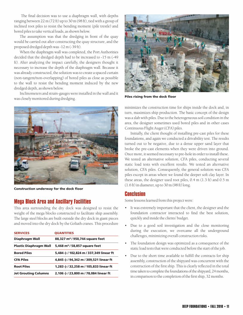
Figure 5: CofferdamPiles rising from the dock floor
SERVICES QUANTITIES
Diaphragm Wall 88,327.00 m² / 947,224.00 square feet
Plastic Diaphragm Wall 5,468.00 m² / 58,857.00 square feet
Bored Piles 5,484 ? / 102,824.00 m / 337,000 linear ft
CFA Piles 4,845 ? / 94,342.00 m / 309,461 linear ft
Root Piles 1,283 ? / 32,258.00 m / 105,807 linear ft
Jet Grouting Columns 2,106 ? / 23,800.00 m / 78,083 linear ft
DFIIOT NA SD INN
SU TO IF T
UPE T
E E
DPRESORTED STANDARD
U.S. POSTAGE PAIDPHILADELPHIA, PAPERMIT NO. 102
Deep Foundations Institute326 Lafayette AvenueHawthorne, NJ 07506 USA973-423-4030Fax 973-423-4031
OPA Winner:Atlântico Sul Shipyard on the coast of Brazil
DEEP FOUNDATIONS • FALL 2010 • 1110 • DEEP FOUNDATIONS • FALL 2010
The final decision was to use a diaphragm wall, with depths
ranging between 22 m (72 ft) up to 30 m (98 ft), tied with a group of
inclined root piles to resist the bending moment (pile trestle) and
bored piles to take vertical loads, as shown below.
The assumption was that the dredging in front of the quay
would be carried out after constructing the quay structure, and the
proposed dredged depth was -12 m (-39 ft).
When the diaphragm wall was completed, the Port Authorities
decided that the dredged depth had to be increased to -15 m (-49
ft). After analyzing the impact carefully, the designers thought it
necessary to increase the depth of the diaphragm wall. Because it
was already constructed, the solution was to create a spaced curtain
(non-tangent/non-overlapping) of bored piles as close as possible
to the wall to resist the bending moment induced by the new
dredged depth, as shown below.
Inclinometers and strain-gauges were installed in the wall and it
was closely monitored during dredging.
This area surrounding the dry dock was designed to resist the
weight of the mega blocks constructed to facilitate ship assembly.
The large steel blocks are built outside the dry dock in giant pieces
and moved into the dry dock by the Goliath cranes. This procedure
Mega Block Area and Ancillary Facilities
minimizes the construction time for ships inside the dock and, in
turn, maximizes ship production. The basic concept of the design
was a slab with piles. Due to the heterogeneous soil condition in the
area, the designer sometimes used bored piles and in other cases
Continuous Flight Auger (CFA) piles.
Initially, the client thought of installing pre-cast piles for these
foundations, and again we conducted a drivability test. The results
turned out to be negative, due to a dense upper sand layer that
broke the pre-cast elements when they were driven into ground.
Once more, it seemed necessary to pre-hole in order to install these.
We tested an alternative solution, CFA piles, conducting several
static load tests with excellent results. We tested an alternative
solution, CFA piles. Consequently, the general solution was CFA
piles except in areas where we found the deeper soft clay layer. In
these areas, the designer used root piles, 0.4 m (1.3 ft) and 0.5 m
(1.6 ft) in diameter, up to 30 m (98 ft) long.
Some lessons learned from this project were:
• It was extremely important that the client, the designer and the
foundation contractor interacted to find the best solution,
quickly and inside the clients’ budget.
• Due to a good soil investigation and the close monitoring
during the execution, we overcame all the underground
challenges, minimizing overall construction risks.
• The foundation design was optimized as a consequence of the
static load tests that were conducted before the start of the job.
• Due to the short time available to fulfill the contracts for ship
assembly, construction of the shipyard was concurrent with the
construction of the first ship. This is clearly reflected in the total
time taken to complete the foundations of the shipyard, 24 months,
in comparison to the completion of the first ship, 32 months.
ConclusionConstruction underway for the dock floor
Figures 6: Quay platform after increasing depth
To save time, all the piles below the slab were installed before the
dry dock excavation, so it was very important to be sure that the pile
cut-off level was preserved and the reinforcement cage was placed in
the right position. The piles were installed by hydraulic rigs up to
260 kNm torque with verticality and depth monitoring systems.
The Overview of the dry dock (Figure 3) shows a general view
and a cross section of the dry dock as well as the mega block paved
area below. Another important part of the dry dock work was the
excavation to concrete the floor slab.
This work was done in steps as follows:
a) Concreting the reinforcement beam over the diaphragm wall
and the mega block paved area
b) Excavating the dry dock up to 3 m (10 ft) below ground level
c) Installing the dewatering system inside and outside the dock area
d) Excavation of the soil in the central part of the floor up to the
final level leaving a berm along the wall
e) Cutting off the pile heads, installing the drainage system,
placing the reinforcement steel and concreting the central part
of the floor slab, repeated until the floor slab was complete
f) After the concrete was cured, excavating the berm up to the
diaphragm wall and final level
The excavation methodology proceeded with the condition that the
diaphragm wall would be monitored in real time by inclinometers
and strain-gauges.
A cofferdam was necessary to excavate and concrete the last part
of the slab, which was closer to sea. A plastic diaphragm wall, 0.6 m
(2 ft) wide with an average depth of 25 m (82 ft) was designed and
executed up to bedrock, to protect the dock.
After completing the slab and installing the dock gate, the fill
and the plastic wall were demolished to allow the final contact of
the dry dock with the sea.
The designer’s first option was to use steel sheet piles. Because of
the soft soil in this region, the problem was the depth that the sheet
piles had to reach to take the vertical load. To establish that the piles
had sufficient load bearing capacity they would have had to be
driven to refusal, and the depth at which this could be achieved
was unpredictable.
Quay Design
Figure 4: Dock floor execution
Figure 3: Overview of the dry dock
Figure 5: CofferdamPiles rising from the dock floor
SERVICES QUANTITIES
Diaphragm Wall 88,327 m² / 950,744 square feet
Plastic Diaphragm Wall 5,468 m² / 58,857 square feet
Bored Piles 5,484 ɸ / 102,824 m / 337,349 linear ft
CFA Piles 4,845 ɸ / 94,342 m / 309,521 linear ft
Root Piles 1,283 ɸ / 32,258 m / 105,833 linear ft
Jet Grouting Columns 2,106 ɸ / 23,800 m / 78,084 linear ft