D-FV-10A6100 5(US) Global Purgemaster - ABB LtdUS).pdf · Data Sheet D-FV-10A6100_5(US) Variable...
18
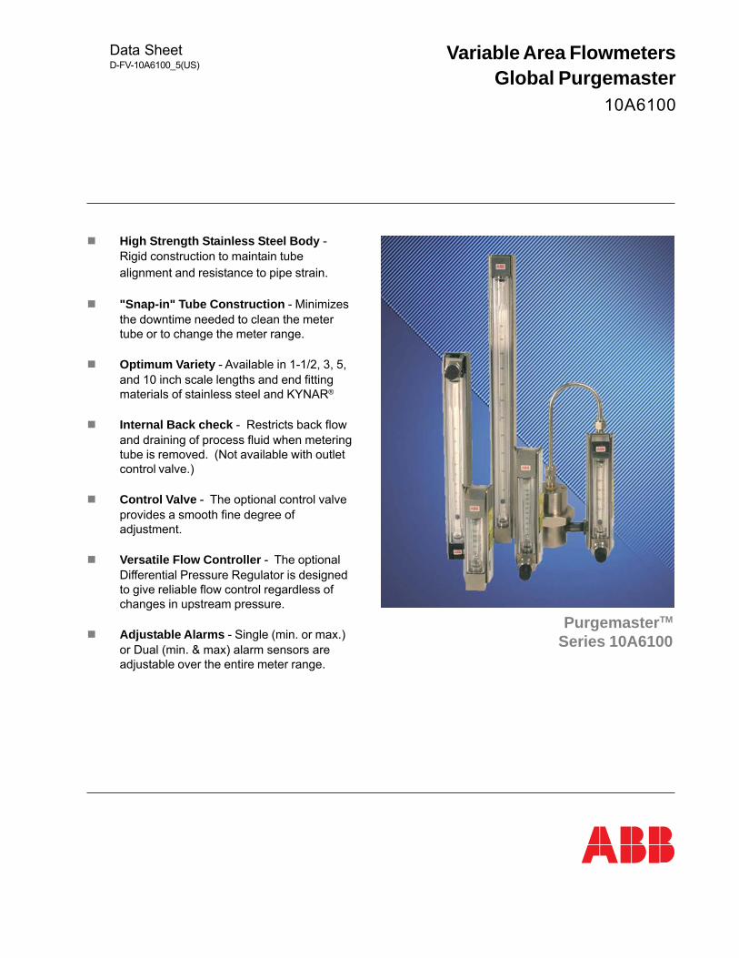
Data Sheet D-FV-10A6100_5(US) Variable Area Flowmeters Global Purgemaster 10A6100 Purgemaster TM Series 10A6100 High Strength Stainless Steel Body - Rigid construction to maintain tube alignment and resistance to pipe strain. "Snap-in" Tube Construction - Minimizes the downtime needed to clean the meter tube or to change the meter range. Optimum Variety - Available in 1-1/2, 3, 5, and 10 inch scale lengths and end fitting materials of stainless steel and KYNAR ® Internal Back check - Restricts back flow and draining of process fluid when metering tube is removed. (Not available with outlet control valve.) Control Valve - The optional control valve provides a smooth fine degree of adjustment. Versatile Flow Controller - The optional Differential Pressure Regulator is designed to give reliable flow control regardless of changes in upstream pressure. Adjustable Alarms - Single (min. or max.) or Dual (min. & max) alarm sensors are adjustable over the entire meter range.
Transcript of D-FV-10A6100 5(US) Global Purgemaster - ABB LtdUS).pdf · Data Sheet D-FV-10A6100_5(US) Variable...
Data SheetD-FV-10A6100_5(US)
Variable Area FlowmetersGlobal Purgemaster
10A6100
PurgemasterTM
Series 10A6100
High Strength Stainless Steel Body -Rigid construction to maintain tubealignment and resistance to pipe strain.
"Snap-in" Tube Construction - Minimizesthe downtime needed to clean the metertube or to change the meter range.
Optimum Variety - Available in 1-1/2, 3, 5,and 10 inch scale lengths and end fittingmaterials of stainless steel and KYNAR®
Internal Back check - Restricts back flowand draining of process fluid when meteringtube is removed. (Not available with outletcontrol valve.)
Control Valve - The optional control valveprovides a smooth fine degree ofadjustment.
Versatile Flow Controller - The optionalDifferential Pressure Regulator is designedto give reliable flow control regardless ofchanges in upstream pressure.
Adjustable Alarms - Single (min. or max.)or Dual (min. & max) alarm sensors areadjustable over the entire meter range.
2
Variable Area FlowmetersPurgemaster - Series 10A6100 D-FV-10A6100_5
PURGEMASTER™
The Purgemaster Purge Meters are low capacityvariable area flowmeters for both liquid and gas withan excellent selection of material and scale lengthsin a single product family design. They provideoptimum flexibility with minimum componentproliferation. The meter features a corrosionresistant, high strength stainless steel body, quick,easy snap-in tube construction and a safety testedoperator protection shield.
The Purgemaster is ideal for such applications asthe purging of control lines and instrumentenclosures. Their use is easily extended into fluidsampling, liquid specific gravity, and levelmeasurement and similar services.
Engineering Specifications
Performance:
Repeatability: 0.5% of full scale reading.
Accuracy:
Rangeability: 10 to 1 or greater
Operational Limits:
Ambient Temperature Limits:32°F to 140°F (0ºC to 60°C)
Minimum Temperature: 32°F (0°C)
Minimum Pressure: Full vacuum. If vacuumconditions require a control valve, it should be in theoutlet fitting.
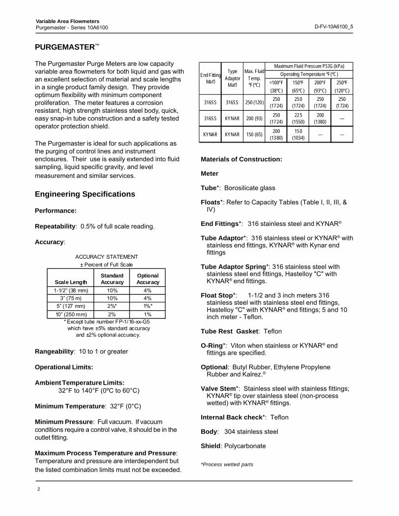
Maximum Process Temperature and Pressure:Temperature and pressure are interdependent butthe listed combination limits must not be exceeded.
Materials of Construction:
Meter
Tube*: Borosilicate glass
Floats*: Refer to Capacity Tables (Table I, II, III, &IV)
End Fittings*: 316 stainless steel and KYNAR®
Tube Adaptor*: 316 stainless steel or KYNAR® withstainless end fittings, KYNAR® with Kynar endfittings
Tube Adaptor Spring*: 316 stainless steel withstainless steel end fittings, Hastelloy "C" withKYNAR® end fittings.
Float Stop*: 1-1/2 and 3 inch meters 316stainless steel with stainless steel end fittings,Hastelloy "C" with KYNAR® end fittings; 5 and 10inch meter - Teflon.
Tube Rest Gasket: Teflon
O-Ring*: Viton when stainless or KYNAR® endfittings are specified.
Optional: Butyl Rubber, Ethylene PropyleneRubber and Kalrez.®
Valve Stem*: Stainless steel with stainless fittings;KYNAR® tip over stainless steel (non-processwetted) with KYNAR® fittings.
Internal Back check*: Teflon
Body: 304 stainless steel
Shield: Polycarbonate
*Process wetted parts
Scale LengthStandard Accuracy
Optional Accuracy
1-1/2” (38 mm) 10% 4%3” (75 m) 10% 4%
5” (127 mm) 2%* 1%*10” (250 mm) 2% 1%
* Except tube number FP-1/16-xx-G5 which have ±5% standard accuracy
and ±2% optional accuracy.
ACCURACY STATEMENT± Percent of Full Scale
<100ºF 150ºF 200ºF 250ºF(38ºC) (65ºC) (93ºC) (120ºC)
316SS 316SS 250 (120) 250 (1724)
250 (1724)
250 (1724)
250 (1724)
316SS KYNAR 200 (93) 250 (1724)
225 (1550)
200 (1380) ---
KYNAR KYNAR 150 (65) 200 (1380)
150 (1034) --- ---
End Fitting Mat’l
Type Adaptor
Mat’l
Max. Fluid Temp. ºF(ºC)
Maximum Fluid Pressure PSIG (kPa)Operating Temperature ºF(ºC)

3
Variable Area FlowmetersPurgemaster - Series 10A6100 D-FV-10A6100_5
Caution
It is important that the process wetted partsmaterials are compatible with the process fluid.Meter damage, with potential resulting unsafeconditions, can occur if the wrong material isused. For example, VITON O-rings MUSTNEVER BE USED FOR AMMONIA SERVICE
WarningOperating the meter without the protection
shield may result in operator bodily injury.
Connections: 1/4 inch NPT. Inlet and outlet fittingsare horizontal and face back.
Mounting: In-line; wall or front of panel throughmounting holes in back of the body; or rearof panel mounting.
Scale Length: 1-1/2, 3, 5, and 10 inch.
Scales (on tube): As indicated in capacity tables.(Optional metal scale for 5 and 10" rearpanel mounting)
Differential Pressure Regulator1
Body: 316 stainless steelDiaphragm: Viton (with stainless body);
Buna-N (optional).Ball Valve: 316 stainless steelSprings: Type 316 stainless steelMax Pressure: 200 psig (1380kPa) at 100°F (38°C)Maximum Differential Pressure:
100 psi (690 kPa)Pipe Connection:
1/4" NPT internal threads
Weight (Approximation)Purge Meter Only
Scale Length lb Kg1-1/2” (38 mm) 1.0 0.45
3” (75 mm) 1.0 0.45
5” (127 mm) 1.4 0.65
10” (250 mm) 1.8 0.80
Purge Meter with Regulator: Add 2-1/2 lb (1.15kg)to weights listed above.
Note 1: When combined with a 53R2110 Differential PressureRegulator, the PURGEMASTER can control a flow of liquid or gasthat is subject to varying line pressure. However, due to gascompressibility, the true value of mass flow rate of a gas can bemeasured only if the downstream pressure remains constant.
Alarms
Principle of operationThe ring sensors with a bistable switching actionpicks up the relay in the amplifier when the ball floatreaches the trigger level and remains in that position,even if the float continues to move towards the alarmzone, thus leaving the trigger level. The relay willdrop out as soon as the float crosses the trigger levelfrom the opposite direction, and moves back from thealarm zone into the normal operating range. Theactual float position - above or below the trigger level- is precisely indicated.
Explosion hazardous operation is feasible, since thering sensor used is an intrinsically safe switch withintrinsically safe circuit. Due to the relatively shortmetering tube, type 10A6131 is suitable either as aminimum or a maximum alarm. Models 10A6132 or10A6133 are recommended if both alarm operationsare required.
Design Features• Sensor height 14 mm, therefore only small
coverage of the scale.• Integrated clamp device directly to the meter
body. No automatically adjustability duringoperation possible.
Alarm Specifications
Ring sensorRC-10-14-N for 1/8 inch meter tubes,RC-10-15-N for 1/4 inch meter tubesBistable Switching ActionFM Approved for
Class I, Div 1, Groups A, B, C and D;Class II, Div 1, Groups E, F, and GClass III, Div 1
Power supply requirements: 5 to 25 V dcLoad Current (current range): ≤ 0.01mA, ≥ .3 mARepeatability: ≤ 0.01 mmSelf Inductance: 100 μHSelf Capacitance: 150 nFAmbient temp. limit: -14°F(-26° C) to 158°F(70°C)Cable: 6 1/2 feet (2m) standard (max. 9800 feet
(3000 m) possible)Housing: Crastin, blackProtective Class: NEMA 4X/IP67Weight: 150 g (approximate)
4
Variable Area FlowmetersPurgemaster - Series 10A6100 D-FV-10A6100_5
Switching amplifier
Type: Pepperl + Fuchs model (s) KFA 5(6)-SR2-Ex.W
Contact rating: max. 250 VA, max. 2A
Supply Voltage: 120 Vac, 240 Vac, ±15%,45 - 65 Hz
Response Time: Energize approximately 20 ms,De-energized approximately 20 ms
Output Type: Single Pole Double Throw (SPDT)
Ambient temp. limits: -4°F (-20°C) to + 140°F(60°C)
Maximum Wire Size: 2.5 mm2 (14 AWG)
Approvals: IP20; Hazardous field circuit EExia IICand FM Class I, Div. 1, Groups A to G. The KFArelay amplifiers must be installed in the non-hazardous area when connected to the RC-10sensors.
Housing Material: Makrolon
Weight: 150 g. (5.2 oz.)
Ordering Information:When ordering, please specify:
Complete model number.Materials of construction (end fittings, regulatorbody).Maximum capacity and unit of flow.Mounting.Type of scale.Accessories.Operating conditions such as:
Fluid measuredOperating and maximum temperatureOperating and maximum pressureFluid densityFluid viscosity
CautionGlass tubes are not recommended for either hot orstrong alkalies; fluorine, or hydrofluoric acid. Metertubes should be periodically inspected for signs ofwear. Erosion, stress cracks or nicks provide earlywarning for tube replacement. With certain fluids,the glass may erode unevenly so that wear is notvisibly noticeable. If wear is suspected, the tubeshould be replaced.
Typical Specifications
The purge meter shall have 304 stainless steelbody, (KYNAR®) (316 stainless steel) end fittingsand (Buna-N) (Viton) O-rings.1
The metering tube shall be easily removable forrange change or cleaning without removing themeter from the line or without the use of tools.
Meter scale length shall be (1-1/2inches percentonly), (3 inches) (5 inches) (10 inches) with(percent) (mm) (direct reading) scale inked directlyon the tube.
Flow rate shall be (range and units) of (fluid)metered at (temperature and pressure). Maximumtemperature and pressure shall be (specify).
When integral control valve is required,2 Add: anintegral (stainless steel) (KYNAR®) control valveshall be provided.
When constant Differential Pressure Regulator isrequired, Add: A stainless steel constantDifferential Pressure Regulator shall be provided tomaintain a constant flow rate with varying linepressures.
1 Viton O-rings with stainless steel and KYNAR® end fitting.2 Always required with Differential Pressure Regulator
5
Variable Area FlowmetersPurgemaster - Series 10A6100 D-FV-10A6100_5
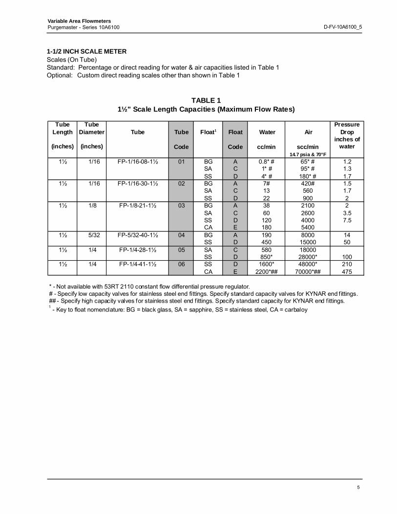
1-1/2 INCH SCALE METERScales (On Tube)Standard: Percentage or direct reading for water & air capacities listed in Table 1Optional: Custom direct reading scales other than shown in Table 1
TABLE 11½" Scale Length Capacities (Maximum Flow Rates)
Tube Length
Tube Diameter Tube Tube Float1 Float Water Air
Pressure Drop
(inches) (inches) Code Code cc/min scc/mininches of
water14.7 psia & 70°F
1½ 1/16 FP-1/16-08-1½ 01 BG A 0.8* # 65* # 1.2SA C 1* # 95* # 1.3SS D 4* # 180* # 1.7
1½ 1/16 FP-1/16-30-1½ 02 BG A 7# 420# 1.5SA C 13 560 1.7SS D 22 900 2
1½ 1/8 FP-1/8-21-1½ 03 BG A 38 2100 2SA C 60 2600 3.5SS D 120 4000 7.5CA E 180 5400
1½ 5/32 FP-5/32-40-1½ 04 BG A 190 8000 14SS D 450 15000 50
1½ 1/4 FP-1/4-28-1½ 05 SA C 580 18000SS D 850* 28000* 100
1½ 1/4 FP-1/4-41-1½ 06 SS D 1600* 48000* 210CA E 2200*## 70000*## 475
* - Not available with 53RT 2110 constant flow differential pressure regulator.# - Specify low capacity valves for stainless steel end fittings. Specify standard capacity valves for KYNAR end fittings.## - Specify high capacity valves for stainless steel end fittings. Specify standard capacity for KYNAR end fittings.1 - Key to float nomenclature: BG = black glass, SA = sapphire, SS = stainless steel, CA = carbaloy
6
Variable Area FlowmetersPurgemaster - Series 10A6100 D-FV-10A6100_5
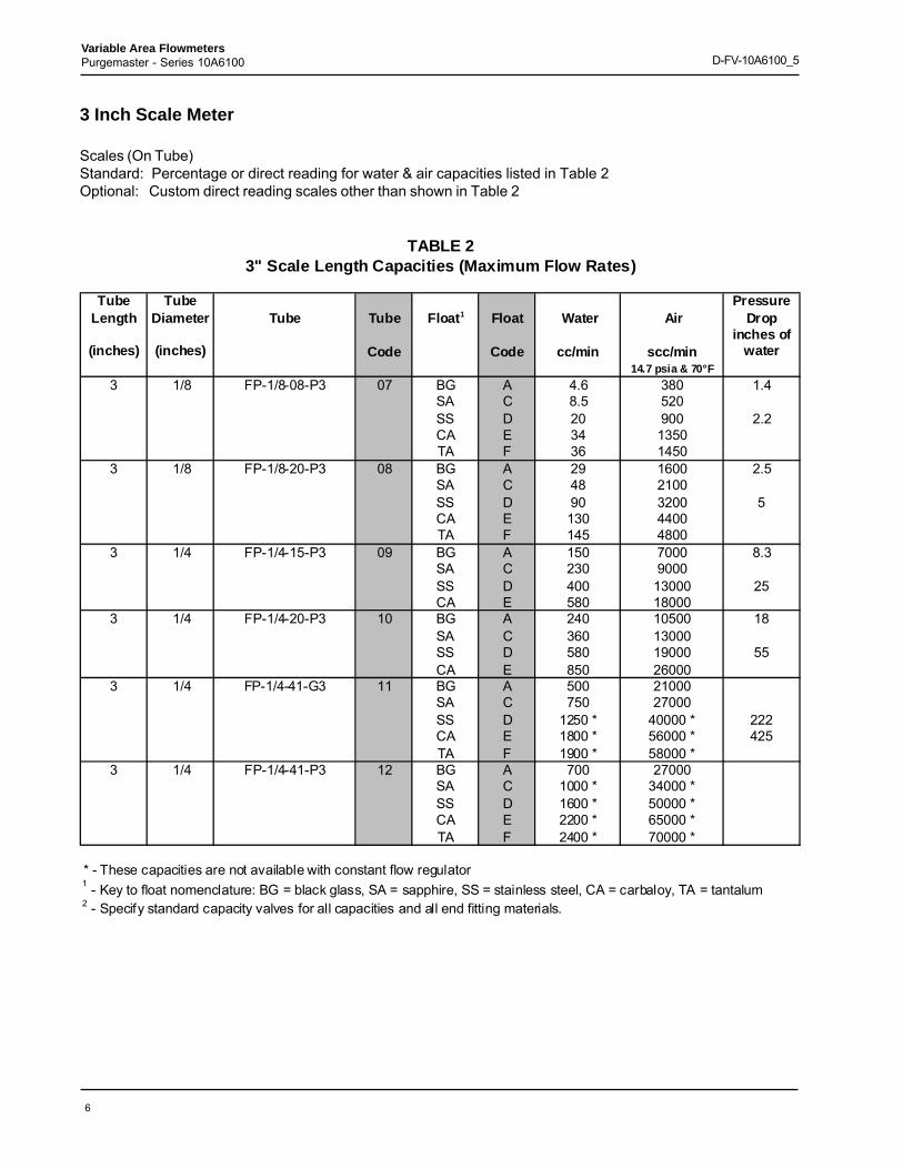
3 Inch Scale Meter
Scales (On Tube)Standard: Percentage or direct reading for water & air capacities listed in Table 2Optional: Custom direct reading scales other than shown in Table 2
TABLE 23" Scale Length Capacities (Maximum Flow Rates)
Tube Length
Tube Diameter Tube Tube Float1 Float Water Air
Pressure Drop
(inches) (inches) Code Code cc/min scc/mininches of
water14.7 psia & 70°F
3 1/8 FP-1/8-08-P3 07 BG A 4.6 380 1.4SA C 8.5 520SS D 20 900 2.2CA E 34 1350TA F 36 1450
3 1/8 FP-1/8-20-P3 08 BG A 29 1600 2.5SA C 48 2100SS D 90 3200 5CA E 130 4400TA F 145 4800
3 1/4 FP-1/4-15-P3 09 BG A 150 7000 8.3SA C 230 9000SS D 400 13000 25CA E 580 18000
3 1/4 FP-1/4-20-P3 10 BG A 240 10500 18SA C 360 13000SS D 580 19000 55CA E 850 26000
3 1/4 FP-1/4-41-G3 11 BG A 500 21000SA C 750 27000SS D 1250 * 40000 * 222CA E 1800 * 56000 * 425TA F 1900 * 58000 *
3 1/4 FP-1/4-41-P3 12 BG A 700 27000SA C 1000 * 34000 *SS D 1600 * 50000 *CA E 2200 * 65000 *TA F 2400 * 70000 *
* - These capacities are not available with constant flow regulator1 - Key to float nomenclature: BG = black glass, SA = sapphire, SS = stainless steel, CA = carbaloy, TA = tantalum2 - Specify standard capacity valves for all capacities and all end fitting materials.
7
Variable Area FlowmetersPurgemaster - Series 10A6100 D-FV-10A6100_5
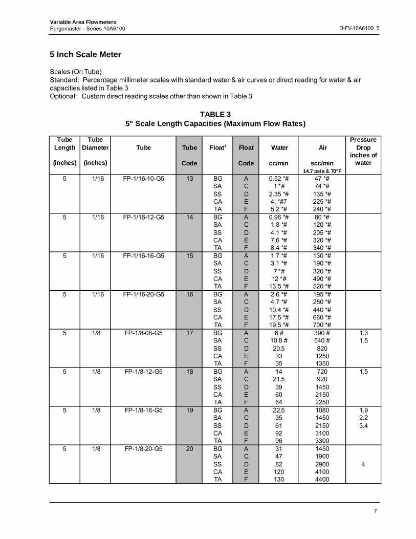
5 Inch Scale Meter
Scales (On Tube)Standard: Percentage millimeter scales with standard water & air curves or direct reading for water & aircapacities listed in Table 3Optional: Custom direct reading scales other than shown in Table 3
TABLE 35" Scale Length Capacities (Maximum Flow Rates)
Tube Length
Tube Diameter Tube Tube Float1 Float Water Air
Pressure Drop
(inches) (inches) Code Code cc/min scc/mininches of
water14.7 psia & 70°F
5 1/16 FP-1/16-10-G5 13 BG A 0.52 *# 47 *#SA C 1 *# 74 *#SS D 2.35 *# 135 *#CA E 4. *#7 225 *#TA F 5.2 *# 240 *#
5 1/16 FP-1/16-12-G5 14 BG A 0.96 *# 80 *#SA C 1.8 *# 120 *#SS D 4.1 *# 205 *#CA E 7.6 *# 320 *#TA F 8.4 *# 340 *#
5 1/16 FP-1/16-16-G5 15 BG A 1.7 *# 130 *#SA C 3.1 *# 190 *#SS D 7 *# 320 *#CA E 12 *# 490 *#TA F 13.5 *# 520 *#
5 1/16 FP-1/16-20-G5 16 BG A 2.6 *# 195 *#SA C 4.7 *# 280 *#SS D 10.4 *# 440 *#CA E 17.5 *# 660 *#TA F 19.5 *# 700 *#
5 1/8 FP-1/8-08-G5 17 BG A 6 # 390 # 1.3SA C 10.8 # 540 # 1.5SS D 20.5 820CA E 33 1250TA F 35 1350
5 1/8 FP-1/8-12-G5 18 BG A 14 720 1.5SA C 21.5 920SS D 39 1450CA E 60 2150TA F 64 2250
5 1/8 FP-1/8-16-G5 19 BG A 22.5 1080 1.9SA C 35 1450 2.2SS D 61 2150 3.4CA E 92 3100TA F 96 3300
5 1/8 FP-1/8-20-G5 20 BG A 31 1450SA C 47 1900SS D 82 2900 4CA E 120 4100TA F 130 4400
8
Variable Area FlowmetersPurgemaster - Series 10A6100 D-FV-10A6100_5
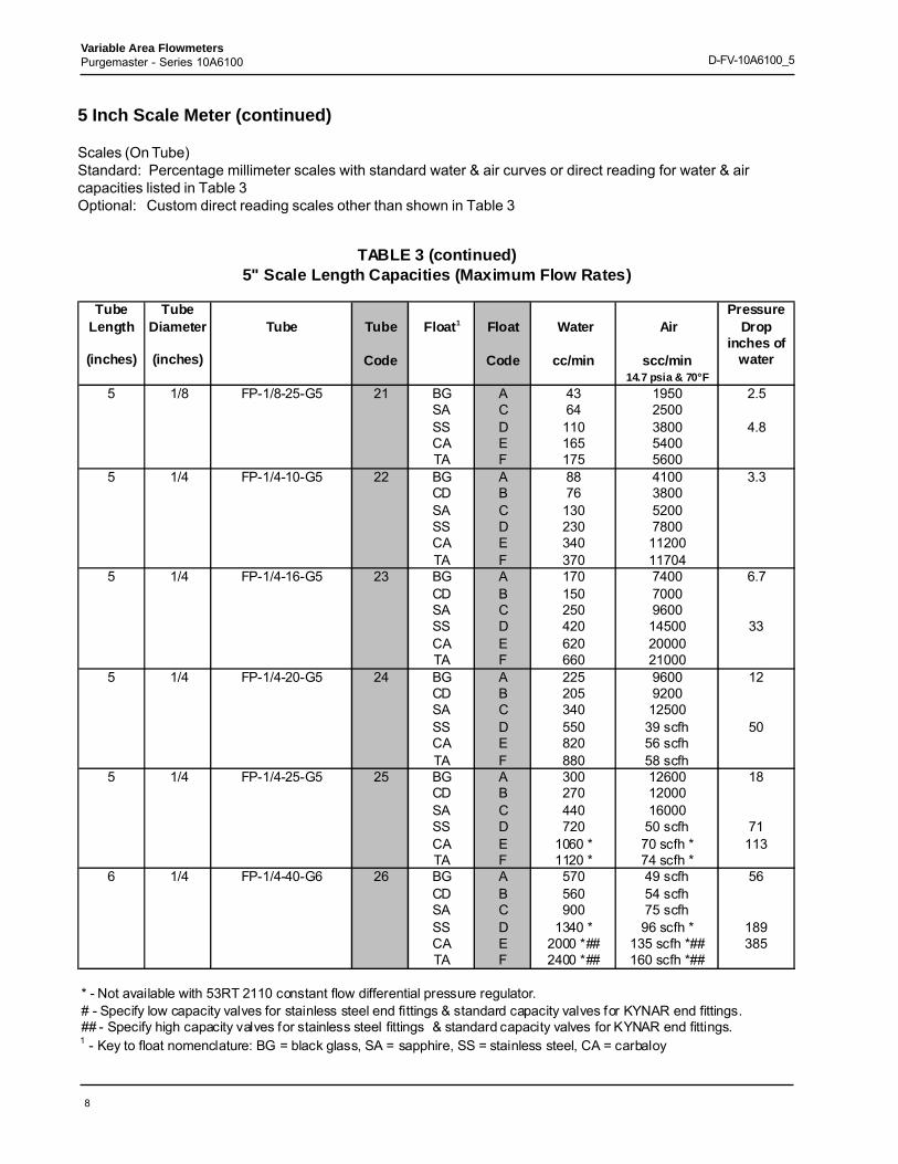
5 Inch Scale Meter (continued)
Scales (On Tube)Standard: Percentage millimeter scales with standard water & air curves or direct reading for water & aircapacities listed in Table 3Optional: Custom direct reading scales other than shown in Table 3
TABLE 3 (continued)5" Scale Length Capacities (Maximum Flow Rates)
Tube Length
Tube Diameter Tube Tube Float1 Float Water Air
Pressure Drop
(inches) (inches) Code Code cc/min scc/mininches of
water14.7 psia & 70°F
5 1/8 FP-1/8-25-G5 21 BG A 43 1950 2.5SA C 64 2500SS D 110 3800 4.8CA E 165 5400TA F 175 5600
5 1/4 FP-1/4-10-G5 22 BG A 88 4100 3.3CD B 76 3800SA C 130 5200SS D 230 7800CA E 340 11200TA F 370 11704
5 1/4 FP-1/4-16-G5 23 BG A 170 7400 6.7CD B 150 7000SA C 250 9600SS D 420 14500 33CA E 620 20000TA F 660 21000
5 1/4 FP-1/4-20-G5 24 BG A 225 9600 12CD B 205 9200SA C 340 12500SS D 550 39 scfh 50CA E 820 56 scfhTA F 880 58 scfh
5 1/4 FP-1/4-25-G5 25 BG A 300 12600 18CD B 270 12000SA C 440 16000SS D 720 50 scfh 71CA E 1060 * 70 scfh * 113TA F 1120 * 74 scfh *
6 1/4 FP-1/4-40-G6 26 BG A 570 49 scfh 56CD B 560 54 scfhSA C 900 75 scfhSS D 1340 * 96 scfh * 189CA E 2000 *## 135 scfh *## 385TA F 2400 *## 160 scfh *##
* - Not available with 53RT 2110 constant flow differential pressure regulator.# - Specify low capacity valves for stainless steel end fittings & standard capacity valves for KYNAR end fittings.## - Specify high capacity valves for stainless steel fittings & standard capacity valves for KYNAR end fittings.1 - Key to float nomenclature: BG = black glass, SA = sapphire, SS = stainless steel, CA = carbaloy
9
Variable Area FlowmetersPurgemaster - Series 10A6100 D-FV-10A6100_5
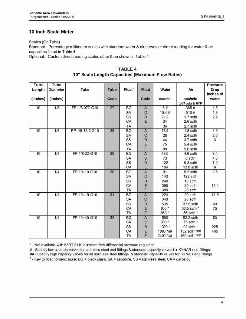
10 Inch Scale Meter
Scales (On Tube)Standard: Percentage millimeter scales with standard water & air curves or direct reading for water & aircapacities listed in Table 4Optional: Custom direct reading scales other than shown in Table 4
TABLE 410" Scale Length Capacities (Maximum Flow Rates)
Tube Length
Tube Diameter Tube Tube Float1 Float Water Air
Pressure Drop
(inches) (inches) Code Code cc/min scc/mininches of
water14.7 psia & 70°F
10 1/8 FP-1/8-077-G10 27 BG A 6 # 365 # 1.5SA C 10.4 # 510 # 1.8SS D 21.2 1.7 scfh 2.2CA E 34 2.6 scfhTA F 36 2.7 scfh
10 1/8 FP-1/8-13.3-G10 28 BG A 16.4 1.8 scfh 1.9SA C 28 2.4 scfh 2.3SS D 44 3.7 scfh 3CA E 75 5.4 scfhTA F 80 5.6 scfh
10 1/8 FP-1/8-32-G10 29 BG A 48.5 4.6 scfh 3.4SA C 73 6 scfh 4.8SS D 122 9.3 scfh 7.9CA E 184 13.8 scfh 9
10 1/4 FP-1/4-10-G10 30 BG A 91 9.2 scfh 2.6SA C 140 122 scfhSS D 240 18 scfhCA E 365 25 scfh 18.4TA F 380 26 scfh
10 1/4 FP-1/4-19-G10 31 BG A 224 20 scfh 11.5SA C 340 26 scfhSS D 535 37.5 scfh 49CA E 800 * 53.5 scfh * 75TA F 850 * 56 scfh *
10 1/4 FP-1/4-40-G10 32 BG A 590 52.2 scfh 63SA C 900 * 75 scfh *SS D 1300 * 92 scfh * 225CA E 1880 *## 132 scfh *## 465TA F 2400 *## 160 scfh *##
* - Not available with 53RT 2110 constant flow differential pressure regulator.# - Specify low capacity valves for stainless steel end fittings & standard capacity valves for KYNAR end fittings.## - Specify high capacity valves for all stainless steel fittings & standard capacity valves for KYNAR end fittings.1 - Key to float nomenclature: BG = black glass, SA = sapphire, SS = stainless steel, CA = carbaloy
10
Variable Area FlowmetersPurgemaster - Series 10A6100 D-FV-10A6100_5
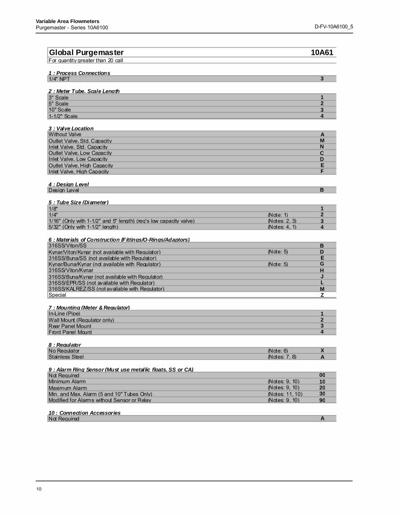
Global Purgemaster 10A61For quantity greater than 20 call
1 : Process Connections1/4" NPT 3
2 : Meter Tube, Scale Length3" Scale 15" Scale 210" Scale 31-1/2" Scale 4
3 : Valve LocationWithout Valve AOutlet Valve, Std. Capacity MInlet Valve, Std. Capacity NOutlet Valve, Low Capacity CInlet Valve, Low Capacity DOutlet Valve, High Capacity EInlet Valve, High Capacity F
4 : Design LevelDesign Level B
5 : Tube Size (Diameter)1/8" 11/4" (Note: 1) 21/16" (Only with 1-1/2" and 5" length) (req's low capacity valve) (Notes: 2, 3) 35/32" (Only with 1-1/2" length) (Notes: 4, 1) 4
6 : Materials of Construction (Fittings/O-Rings/Adaptors)316SS/Viton/SS BKynar/Viton/Kynar (not available with Regulator) (Note: 5) D316SS/Buna/SS (not available with Regulator) EKynar/Buna/Kynar (not available with Regulator) (Note: 5) G316SS/Viton/Kynar H316SS/Buna/Kynar (not available with Regulator) J316SS/EPR/SS (not available with Regulator) L316SS/KALREZ/SS (not available with Regulator) MSpecial Z
7 : Mounting (Meter & Regulator)In-Line (Pipe) 1Wall Mount (Regulator only) 2Rear Panel Mount 3Front Panel Mount 4
8 : RegulatorNo Regulator (Note: 6) XStainless Steel (Notes: 7, 8) A
9 : Alarm Ring Sensor (Must use metallic floats, SS or CA)Not Required 00Minimum Alarm (Notes: 9, 10) 10Maximum Alarm (Notes: 9, 10) 20Min. and Max. Alarm (5 and 10" Tubes Only) (Notes: 11, 10) 30Modified for Alarms without Sensor or Relay (Notes: 9, 10) 90
10 : Connection AccessoriesNot Required A
11
Variable Area FlowmetersPurgemaster - Series 10A6100 D-FV-10A6100_5
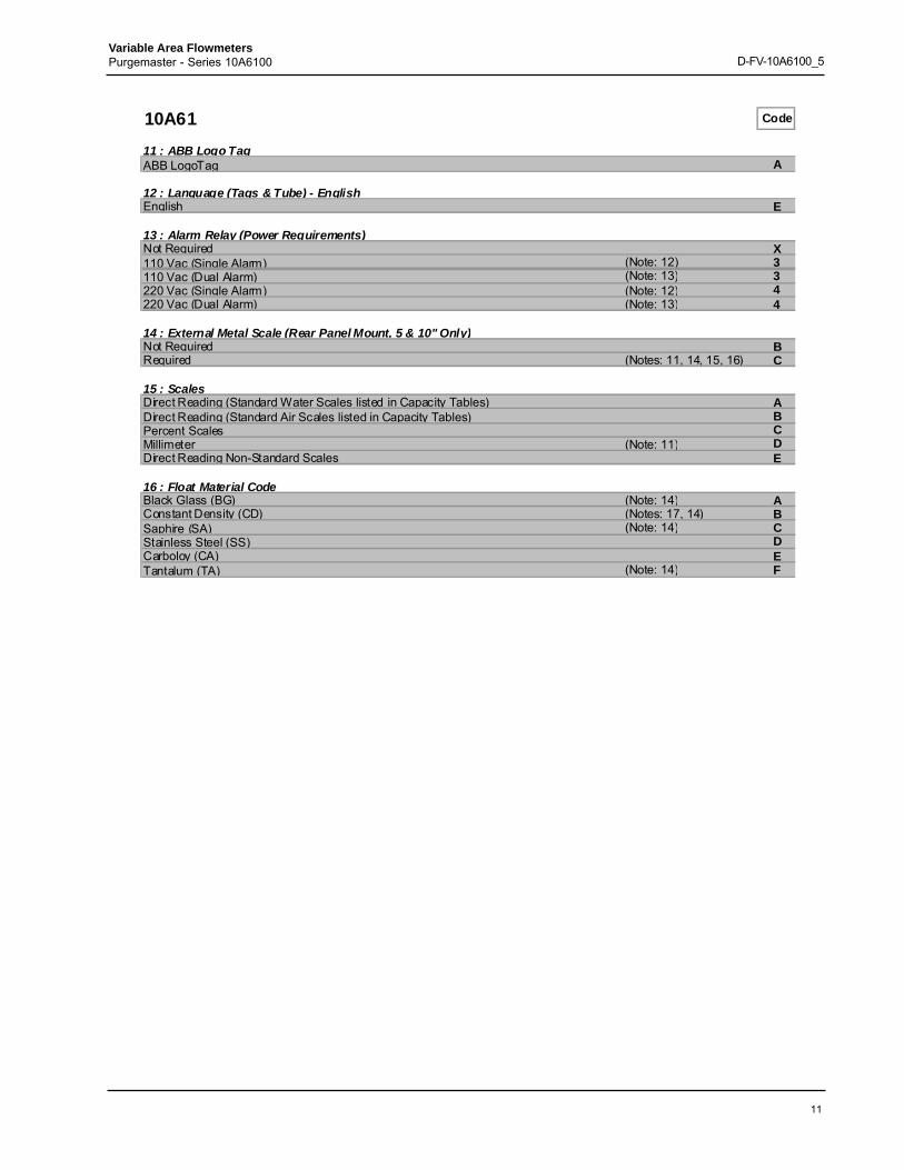
10A61 Code
11 : ABB Logo TagABB LogoTag A
12 : Language (Tags & Tube) - EnglishEnglish E
13 : Alarm Relay (Power Requirements)Not Required X110 Vac (Single Alarm) (Note: 12) 3110 Vac (Dual Alarm) (Note: 13) 3220 Vac (Single Alarm) (Note: 12) 4220 Vac (Dual Alarm) (Note: 13) 4
14 : External Metal Scale (Rear Panel Mount, 5 & 10" Only)Not Required BRequired (Notes: 11, 14, 15, 16) C
15 : ScalesDirect Reading (Standard Water Scales listed in Capacity Tables) ADirect Reading (Standard Air Scales listed in Capacity Tables) BPercent Scales CMillimeter (Note: 11) DDirect Reading Non-Standard Scales E
16 : Float Material CodeBlack Glass (BG) (Note: 14) AConstant Density (CD) (Notes: 17, 14) BSaphire (SA) (Note: 14) CStainless Steel (SS) DCarboloy (CA) ETantalum (TA) (Note: 14) F
12
Variable Area FlowmetersPurgemaster - Series 10A6100 D-FV-10A6100_5
10A61 Code
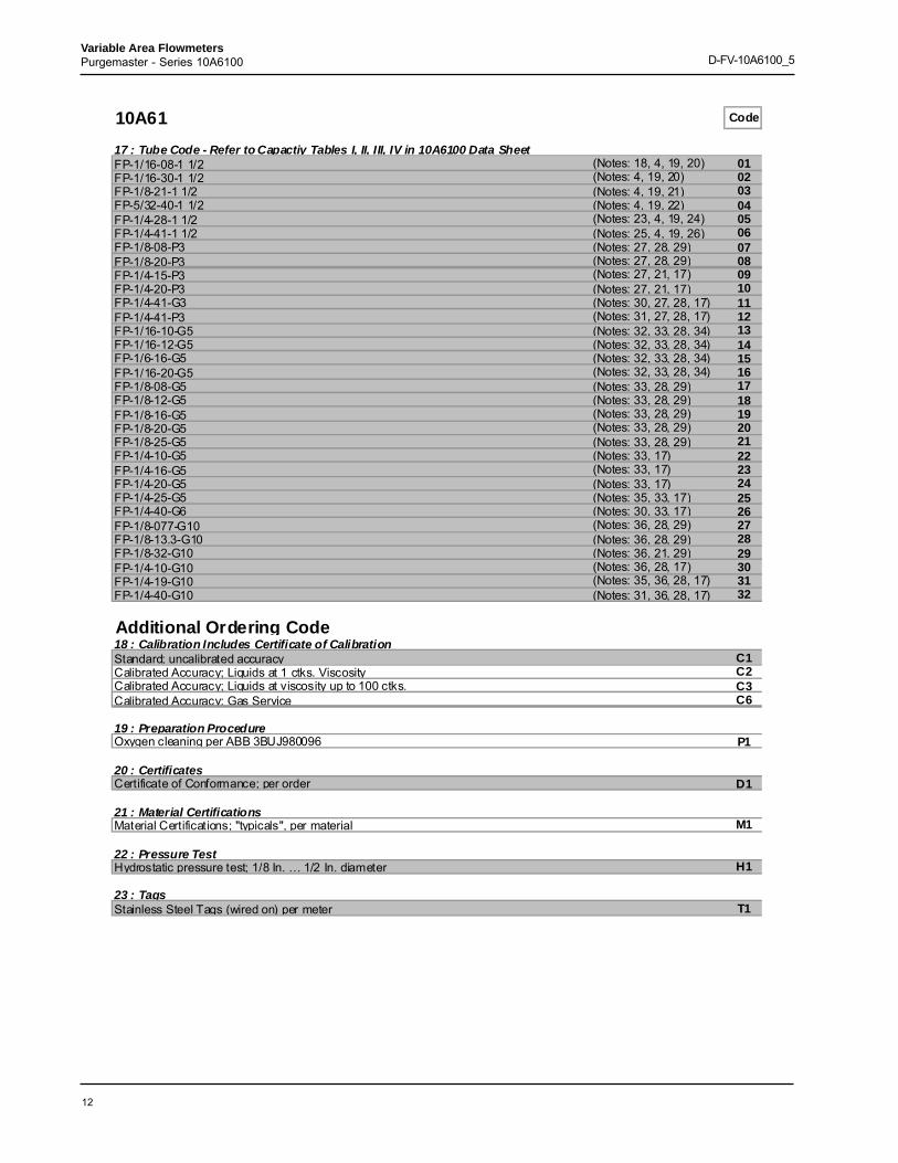
17 : Tube Code - Refer to Capactiy Tables I, II, III, IV in 10A6100 Data SheetFP-1/16-08-1 1/2 (Notes: 18, 4, 19, 20) 01FP-1/16-30-1 1/2 (Notes: 4, 19, 20) 02FP-1/8-21-1 1/2 (Notes: 4, 19, 21) 03FP-5/32-40-1 1/2 (Notes: 4, 19, 22) 04FP-1/4-28-1 1/2 (Notes: 23, 4, 19, 24) 05FP-1/4-41-1 1/2 (Notes: 25, 4, 19, 26) 06FP-1/8-08-P3 (Notes: 27, 28, 29) 07FP-1/8-20-P3 (Notes: 27, 28, 29) 08FP-1/4-15-P3 (Notes: 27, 21, 17) 09FP-1/4-20-P3 (Notes: 27, 21, 17) 10FP-1/4-41-G3 (Notes: 30, 27, 28, 17) 11FP-1/4-41-P3 (Notes: 31, 27, 28, 17) 12FP-1/16-10-G5 (Notes: 32, 33, 28, 34) 13FP-1/16-12-G5 (Notes: 32, 33, 28, 34) 14FP-1/6-16-G5 (Notes: 32, 33, 28, 34) 15FP-1/16-20-G5 (Notes: 32, 33, 28, 34) 16FP-1/8-08-G5 (Notes: 33, 28, 29) 17FP-1/8-12-G5 (Notes: 33, 28, 29) 18FP-1/8-16-G5 (Notes: 33, 28, 29) 19FP-1/8-20-G5 (Notes: 33, 28, 29) 20FP-1/8-25-G5 (Notes: 33, 28, 29) 21FP-1/4-10-G5 (Notes: 33, 17) 22FP-1/4-16-G5 (Notes: 33, 17) 23FP-1/4-20-G5 (Notes: 33, 17) 24FP-1/4-25-G5 (Notes: 35, 33, 17) 25FP-1/4-40-G6 (Notes: 30, 33, 17) 26FP-1/8-077-G10 (Notes: 36, 28, 29) 27FP-1/8-13.3-G10 (Notes: 36, 28, 29) 28FP-1/8-32-G10 (Notes: 36, 21, 29) 29FP-1/4-10-G10 (Notes: 36, 28, 17) 30FP-1/4-19-G10 (Notes: 35, 36, 28, 17) 31FP-1/4-40-G10 (Notes: 31, 36, 28, 17) 32
Additional Ordering Code18 : Calibration Includes Certificate of CalibrationStandard; uncalibrated accuracy C1Calibrated Accuracy; Liquids at 1 ctks. Viscosity C2Calibrated Accuracy; Liquids at viscosity up to 100 ctks. C3Calibrated Accuracy; Gas Service C6
19 : Preparation ProcedureOxygen cleaning per ABB 3BUJ980096 P1
20 : CertificatesCertificate of Conformance; per order D1
21 : Material CertificationsMaterial Certifications; "typicals", per material M1
22 : Pressure TestHydrostatic pressure test; 1/8 In. … 1/2 In. diameter H1
23 : TagsStainless Steel Tags (wired on) per meter T1
13
Variable Area FlowmetersPurgemaster - Series 10A6100 D-FV-10A6100_5
Note 1: Not available with Valve Location code C, DNote 2: Not available with Valve Location code M, N, E, FNote 3: Not available with Meter Tube, Scale Length code 1, 3Note 4: Not available with Meter Tube, Scale Length code 1, 2, 3Note 5: Not available with Valve Location code C, D, E, FNote 6: Not available with Mounting (Meter & Regulator) code 2Note 7: Not available with Materials of Construction (Fittings/O-Rings/Adaptors) code D, E, G, J, L, MNote 8: Not available with Tube Size (Diameter) code 3Note 9: Not available with Meter Tube, Scale Length code 4Note 10: Not available with Tube Size (Diameter) code 3, 4Note 11: Not available with Meter Tube, Scale Length code 1, 4Note 12: Not available with Alarm Ring Sensor (Must use metallic floats, SS or CA) code 00, 30, 90Note 13: Not available with Alarm Ring Sensor (Must use metallic floats, SS or CA) code 00, 10, 20, 90Note 14: Not available with Alarm Ring Sensor (Must use metallic floats, SS or CA) code 10, 20, 30, 90Note 15: Not available with Alarm Relay (Power Requirements) code 3, 4Note 16: Not available with Mounting (Meter & Regulator) code 1, 2, 4Note 17: Not available with Tube Size (Diameter) code 1, 3, 4Note 18: Not available with Float Material Code code A, C, D and Regulator code ANote 19: Not available with Scales code A, B, DNote 20: Not available with Float Material Code code B, E, FNote 21: Not available with Float Material Code code B, FNote 22: Not available with Float Material Code code B, C, E, FNote 23: Not available with Float Material Code code D and Regulator code ANote 24: Not available with Float Material Code code A, B, E, FNote 25: Not available with Float Material Code code D, E and Regulator code ANote 26: Not available with Float Material Code code A, B, C, FNote 27: Not available with Meter Tube, Scale Length code 2, 3, 4Note 28: Not available with Float Material Code code BNote 29: Not available with Tube Size (Diameter) code 2, 3, 4Note 30: Not available with Float Material Code code D, E, F and Regulator code ANote 31: Not available with Float Material Code code C, D, E, F and Regulator code ANote 32: Not available with Float Material Code code A, C, D, E, F and Regulator code ANote 33: Not available with Meter Tube, Scale Length code 1, 3, 4Note 34: Not available with Tube Size (Diameter) code 1, 2, 4Note 35: Not available with Float Material Code code E, F and Regulator code ANote 36: Not available with Meter Tube, Scale Length code 1, 2, 4
14
Variable Area FlowmetersPurgemaster - Series 10A6100 D-FV-10A6100_5
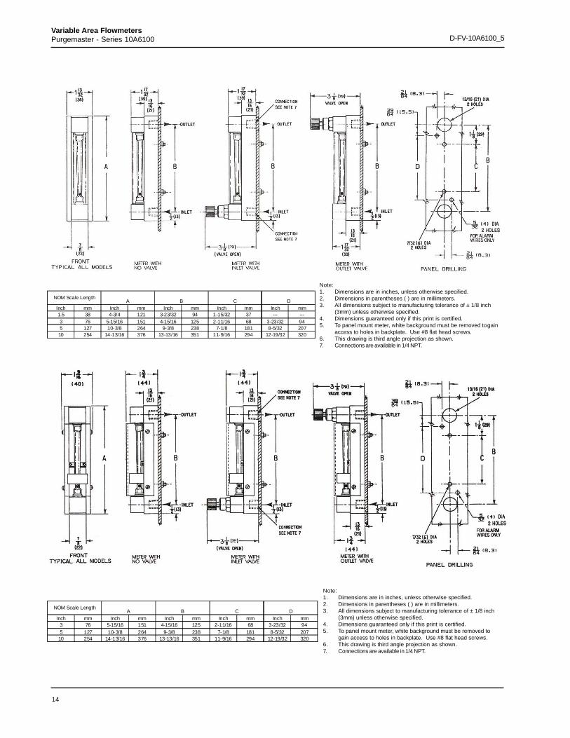
Note:1. Dimensions are in inches, unless otherwise specified.2. Dimensions in parentheses ( ) are in millimeters.3. All dimensions subject to manufacturing tolerance of ± 1/8 inch
(3mm) unless otherwise specified.4. Dimensions guaranteed only if this print is certified.5. To panel mount meter, white background must be removed togain
access to holes in backplate. Use #8 flat head screws.6. This drawing is third angle projection as shown.7. Connections are available in 1/4 NPT.
Note:1. Dimensions are in inches, unless otherwise specified.2. Dimensions in parentheses ( ) are in millimeters.3. All dimensions subject to manufacturing tolerance of ± 1/8 inch
(3mm) unless otherwise specified.4. Dimensions guaranteed only if this print is certified.5. To panel mount meter, white background must be removed to
gain access to holes in backplate. Use #8 flat head screws.6. This drawing is third angle projection as shown.7. Connections are available in 1/4 NPT.
Inch mm Inch mm Inch mm Inch mm Inch mm1.5 38 4-3/4 121 3-23/32 94 1-15/32 37 --- ---3 76 5-15/16 151 4-15/16 125 2-11/16 68 3-23/32 945 127 10-3/8 264 9-3/8 238 7-1/8 181 8-5/32 207
10 254 14-13/16 376 13-13/16 351 11-9/16 294 12-19/32 320
C DNOM Scale Length
A B
Inch mm Inch mm Inch mm Inch mm Inch mm3 76 5-15/16 151 4-15/16 125 2-11/16 68 3-23/32 945 127 10-3/8 264 9-3/8 238 7-1/8 181 8-5/32 207
10 254 14-13/16 376 13-13/16 351 11-9/16 294 12-19/32 320
NOM Scale LengthA B C D
15
Variable Area FlowmetersPurgemaster - Series 10A6100 D-FV-10A6100_5
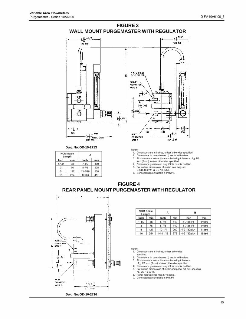
FIGURE 3WALL MOUNT PURGEMASTER WITH REGULATOR
Dwg. No: OD-10-2713
NOM ScaleLength A
Inch mm Inch mm1-1/2 38 7-1/2 190
3 76 8-7/8 2255 127 13-5/16 33810 254 17-3/4 451
Notes:1. Dimensons are in inches, unless otherwise specified.2. Dimensions in parentheses ( ) are in millimeters.3. All dimensions subject to manufacturing tolerance of + 1/8
inch (3mm), unless otherwise specified.4. Dimensions guaranteed only if this print is certified.5. For outline dimensions of meter, see dwg. no.
C-OD-10-2711 & OD-10-2750.6. Connections are available in 1/4 NPT.
FIGURE 4REAR PANEL MOUNT PURGEMASTER WITH REGULATOR
NOM ScaleLength A B
Inch mm Inch mm Inch mm1-1/2 38 5-7/8 149 5-7/8±1/4 149±6
3 76 5-7/8 149 5-7/8±1/4 149±65 127 10-1/4 260 4-21/32±1/4 118±610 254 14-11/16 373 4-21/32±1/4 188±6
Notes:1. Dimensons are in inches, unless otherwise
specified.2. Dimensions in parentheses ( ) are in millimeters.3. All dimensions subject to manufacturing tolerance
of + 1/8 inch (3mm), unless otherwise specified.4. Dimensions guaranteed only if this print is certified.5. For outline dimensions of meter and panel cut-out, see dwg.
no. OD-10-2715.6. Panel hardware for max 5/16 panel.7. Connections are available in 1/4 NPT
Dwg. No: OD-10-2716
16
Variable Area FlowmetersPurgemaster - Series 10A6100 D-FV-10A6100_5
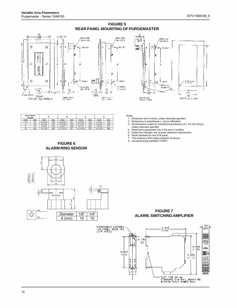
FIGURE 5REAR PANEL MOUNTING OF PURGEMASTER
Nom ScaleLength A B C D
Inch mm Inch mm Inch mm Inch mm Inch mm1-1/2 38 4-31/32 126 3-23/32 94 4-27/32 123 5-3/32 129
3 76 6-3/16 157 4-15/16 125 6-1/16 154 6-5/16 1605 127 10-5/8 270 9-3/8 238 10-1/2 267 10-3/4 273
10 254 15-1/16 383 13-13/16 351 14-15/16 379 15-3/16 386
Notes:1. Dimensons are in inches, unless otherwise specified.2. Dimensions in parentheses ( ) are in millimeters.3. All dimensions subject to manufacturing tolerance of + 1/8 inch (3mm),
unless otherwise specified.4. Dimensions guaranteed only if this print is certified.5. Dotted line indicates rear of panel clearance requirements.6. Panel hardware for max 5/16 panel.7. This drawing is third angle projection as shown.8. Connections are available in 1/4 NPT.
FIGURE 6ALARM RING SENSOR
FIGURE 7ALARM, SWITCHING AMPLIFIERDiameter 1/8” 1/4"
A (mm) 10 15
17
Variable Area FlowmetersPurgemaster - Series 10A6100 D-FV-10A6100_5
Notes
18
Variable Area FlowmetersPurgemaster - Series 10A6100 D-FV-10A6100_5
The Company’s policy is one of continuous productimprovement and the right is reserved to modify the
information contained herein without notice.
Printed in USA (8.6.09)© ABB 2003, 2009
D-F
V-10
A61
00_5
(US
)ABB (www.abb.com) is a leader in power and automation technologies that enableutility and industry customers to improve their performance while loweringenvironmental impact. The ABB Group of companies operates in around 100countries and employs about 120,000 people.
www.abb.com/instrumentation
ABB Inc.125 East County Line RoadWarminster, PA 18974USA
Tel: +1 215 674 6000Fax: +1 215 674 7183