CYLINDRICAL BRILLOUIN FLOW IN RELATIVISTIC SMOOTH-BORE ...
16
PFC/JA-88-48 CYLINDRICAL BRILLOUIN FLOW IN RELATIVISTIC SMOOTH-BORE MAGNETRONS Ronald C. Davidson George L. Johnston Kang T. Tsang* Adam T. Drobot* December, 1988 Plasma Fusion Center Massachusetts Institute of Technology Cambridge, MA 02139 *Science Applications International Corp. 8200 Greensborough Drive, McLean, VA 22102
Transcript of CYLINDRICAL BRILLOUIN FLOW IN RELATIVISTIC SMOOTH-BORE ...

PFC/JA-88-48
CYLINDRICAL BRILLOUIN FLOW IN RELATIVISTIC
SMOOTH-BORE MAGNETRONS
Ronald C. DavidsonGeorge L. Johnston
Kang T. Tsang*Adam T. Drobot*
December, 1988
Plasma Fusion CenterMassachusetts Institute of Technology
Cambridge, MA 02139
*Science Applications International Corp.8200 Greensborough Drive, McLean, VA 22102

CYLINDRICAL BRILLOUIN FLOW IN RELATIVISTIC SMOOTH-BORE MAGNETRONS
Ronald C. Davidson and George L. Johnston
Plasma Fusion Center, Massachusetts Institute of Technology
167 Albany Street, Cambridge, Massachusetts 02139
Kang T. Tsang and Adam T. Drobot
Science Applications International Corporation
8200 Greensborough Drive, McLean, Virginia 22102
ABSTRACT
A macroscopic cold-fluid model is used to determine the influence
of cylindrical effects on the operating range and properties of the
electron flow in relativistic smooth-bore magnetrons. Assuming
operation at Brillouin flow, it is found that cylindrical effects
(such as the centrifugal force on an electron fluid element) can
significantly modify several features of the equilibrium flow and
diode operating range relative to the case of planar flow.
1. INTRODUCTION
In relativistic magnetrons,1-6 pulsed, high-voltage diodes
(operating in the MV range, say) are used to generate microwaves at
gigawatt power levels. While magnetically insulated electron flow 7 ,8
and related features of the magnetron instability9 ~1 3 have been
extensively analyzed in planar geometry, there are relatively few
theoretical treatments that attempt to retain the full influence of
self-field and cylindrical effects (centrifugal force effects, finite
diode aspect ratio, etc.) on the diode operating range and equilib-
rium profiles as well as stability behavior. 15,16 In this paper, a
macroscopic cold-fluid model is used to determine the detailed in-
fluence of cylindrical effects on the operating range and properties
of the equilibrium electron flow in relativistic smooth-bore magne-
trons. Assuming operation at Brillouin flow, the normalized layer
thickness and Hull cut-off voltage are calculated over a wide range
of diode aspect ratio a/(b - a), and normalized fill field2
eBf(b - a)/mc2. THEORETICAL MODEL
In the present analysis, we make use of a macroscopic cold-fluid
model to investigate equilibrium properties of relativistic, non-

2
neutral electron flow in the cylindrical smooth-bore magnetron con-
figuration illustrated in Fig. 1. All equilibrium properties are
assumed to be azimuthally symmetric (a/80 - 0) and independent ofaxial coordinate (a/8z - 0). The cathode is located at r - a, the
anode is located at r = b, and space-charge-limited flow is assumed
with
f (r = a) = 0 and *0 (r = b) = V,
(1)Er(r = a) =0.
Here, V is the applied voltage, *0 (r) is the electrostatic potential,
and Er (r) - -8+ 0/8r is the radial electric field. The combined
radial electric field Er (r)&r and axial magnetic field B z(r) z pro-
duce an equilibrium rotation of the nonneutral electron fluid with
normalized azimuthal flow velocity
Ob(r) = VOb(r)/c - wb(r)r/c (2)
where c is the speed of light in vacuo. It is assumed that the equi-
librium density profile nb(r) extends from the cathode at r - a to
radius r - rb (the outer edge of the electron layer), and that the
region rb < r < b corresponds to a vacuum region. The electric and
magnetic fields are determined self-consistently from
1 a- - rE r(r) = - 4 nenb(r) , (3)r ar r
a- B z(r) = 4 nenb(r)0b(r) , (4)ar
where -e is the electron charge. In the subsequent analysis, the
applied magnetic field in the vacuum region is denoted by
Bz(r) = B0 = const., rb < r < b . (5)
To complete the macroscopic cold-fluid equilibrium description,
Eqs.(3) and (4) are supplemented by the radial force balance equation
2 e
-Yb(r)O b (r) = 2 [rEr(r) + 0 b(r)rBz (r) , (6)
where m is the electron rest mass, and

3
ANODE
C AT HOD E
r b a / d
0 b
B (x)=Bz (r) r8
0(r=a)=O
8b~r
qo (r=b)=V
Fig. 1. Cylindrical smooth-bore magnetron.
Yb(r) = [1 - 02(r)]-1/2 (7)
is the relativistic mass factor. Consistent with Er(r - a) = 0 inEq.(l), we consider the class of solutions to Eq.(6) in which thereis zero flow velocity at the cathode, i.e.,
0b(r - a) - 0. (8)
Equations (3), (4) and (6), supplemented by the boundary condi-tions in Eqs.(1), (5) and (8), can be used to calculate the equilib-rium profiles Er(r), Bz (r), nb(r) and Ob(r). Generally speaking,there is considerable latitude in the choice of equilibrium profilesin a macroscopic cold-fluid model.14 For example, the radial de-pendence of any one of the profiles Er(r), Bz(r), nb(r) and 0b(r) canbe prescribed arbitrarily, and the three remaining profiles calcu-lated self-consistently from Eqs.(3), (4) and (6).
4
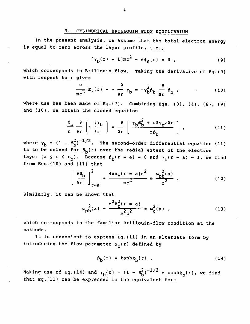
3. CYLINDRICAL BRILLOUIN FLOW EQUILIBRIUM
In the present analysis, we assume that the total electron energy
is equal to zero across the layer profile, i.e.,
[yb(r) - 1]mc 2 ef 0 (r) 0 - (9)
which corresponds to Brillouin flow. Taking the derivative of Eq.(9)with respect to r gives
e3
-- 2 E r(r) a ' - ybib 1b 0)mc 8r 8r
where use has been made of Eq.(7). Combining Eqs. (3), (4), (6), (9)and (10), we obtain the closed equation
b r ab a b0 + rayb/ 1
r ar ar J r r0 Jbwhere yb - (1 1/2. The second-order differential equation (11)
is to be solved for 0b(r) over the radial extent of the electron
layer (a < r < rb). Because 0b(r - a) = 0 and Yb(r - a) - 1, we find
from Eqs.(10) and (11) that
a0b 2 4 nnb(r - a)e2 W 2(a)--- J 2 - 2 .(12)ar r=a mc c
Similarly, it can be shown that
e2B2(r - a) 2W pb (a) = m22 c (a) , (13)
which corresponds to the familiar Brillouin-flow condition at the
cathode.
It is convenient to express Eq.(11) in an alternate form by
introducing the flow parameter Xb(r) defined by
0b(r) = tanhXb(r) . (14)
Making use of Eq.(14) and yb(r) = (1 - 0 ) = coshXb(r), we find
that Eq.(11) can be expressed in the equivalent form

5
1 a ( Xb sinhXbcoshXb-r -- r --- -r 2 .(15)r ar ar r2
Consistent with Eq.(12) and gb(r - a) - 0, Eq.(15) is to be solvedsubject to the boundary conditions
Xb(r = a) - 0
[ aXb 12 2Kb(a) 2 K (16)Lr r-a c
Integrating Eq.(15) with respect to r, we obtain
r - K2a2 + sinh 2X ' (17)ar
where the boundary conditions in Eq.(16) have been enforced.
Equation (17) is the final equation describing equilibrium
Brillouin flow in cylindrical diode geometry. In this regard,
Eq.(17) is applicable within the electron layer (a < r < rb) and must
be solved subject to the boundary condition Xb(r - a) = 0, which
corresponds to ab(r - a) - 0. Numerical solutions to Eq.(17) are
presented in Fig. 2, where Xb(r) is plotted versus K(r - a) for
several choices of the dimensionless parameter Ka. As a general
remark, for large aspect ratio and a thin layer satisfying
K2a2 >> sinh 2Xb(18)
(rb - a)2 << a2
it is readily shown that the solution to Eq.(17) reduces to the
familiar planar result1
Xb(r) = K(r - a) , (19)
which corresponds to normalized flow velocity 0b(r) - tanh[K(r - a)]
within the electron layer (a < r < rb). When Eq.(18) is not satis-
fied, it is clear from Fig. 2 that the cylindrical effects in Eq.(17)
can significantly modify the solution for Xb(r) relative to theplanar result in Eq.(19).

6
7.0
Ka= 26.0 3
45.0- 5
~ 10'4.0 -
3.0-
2.0-
1.0
0 - I i I , I , I fI i I i0 0.5 1.0 1.5 2.0 2.5 3.0 3.5 4.0
K(r-a)
Fig. 2. Plots of Xb versus K(r - a) obtained from
Eq.(17) for several values of Ka.
4. VOLTAGE AND FILL-FIELD CONDITIONS
The equilibrium electric and magnetic field profiles, E r(r) and
B Z (r), are readily expressed in terms of Xb(r) by making use of
Eqs.(3) and (4). Without presenting algebraic details, we integrate
Poisson's equation (3) from r = a to r = b and enforce +0 (r - b) - V,where V is the applied voltage at the anode. This gives
eV !Xb b+ rsinhXb l n (20)
mc r=rb 8r r=rb r b
which relates Xb(r = rb) and [Xb/8rl r-r at the surface of the
electron layer to the normalized voltagebeV/mc2 . Furthermore, web
make use of magnetic flux conservation, 2nfdrrBz = const., to relatea
the initial fill field Bf (assumed to be uniform prior to formation
of the electron layer) to the magnetic field depression after the

7
layer is formed. Making use of eBz/mc2 - r~ (/ar)(rsinhXb) withinthe electron layer (a _ r < rb), we obtain
eB(b - a) (b2 + r2) (b2 - )Xb]2 r [sinhXb r - r + rcoshXbmc rb(b + a) b rb(b + a) Lr r - r
(21)
Equations (20) and (21) relate eV/mc2 and eBf(b - a)/mc2 to rb'Xb(r - rb), [8Xb/ 8 r-r , and the geometric factors a and b.
bGenerally speaking, the equilibrium flow equation (17) for Xb(r) mustbe integrated with respect to r to determine Xb(r - rb) and
[aXb r - r b in Eqs.(20) and (21).
Cylindrical effects are included in Eqs.(20) and (21) in a fullyself-consistent manner. As shown in Sec. 7, Eqs.(20) and (21),
together with Eq.(17), can be used to determine numerically the
normalized layer thickness A - (rb - a)/(b - a) in terms of the
normalized voltage eV/mc2 and fill field eBf(b - a)/mc , and the
geometric factors a and b. For completeness, we first consider
Eqs.(17), (20) and (21) in the limit of a planar diode.
5. RELATIVISTIC PLANAR FLOW
In the limit of a planar diode with (b - a)2 << a 2, (rb - a)2
<< a2 and K2 a2 >> sinh2 Xb(r - rb)J, it is readily shown that the
solution to Eq.(17) reduces to the familiar result Xb(r) = K(r - a)
over the radial extent of the electron layer (a < r < rb), and that
Eqs.(20) and (21) can be approximated by
eV1 + -2 = cosh K(rb - a) + K(b - rb) sinh K(rb - a), (22)
mc
eB f(b - a)
e c 2 - sinh K(rb - a)] + K(b - rb) cosh K(rb - a) . (23)
For specified value of the normalized fill field eBf(b - a)/mc2the voltage eV/mc must be sufficiently small to assure magnetically
insulated flow with rb < b, i.e., the outer edge of the electron
layer is not in contact with the anode. Examination of Eqs.(22) and

8
(23) shows that the condition rb < b requires that the voltage V must
be smaller than the Hull cut-off voltage VH defined by 2 ,4
eVH e [1 B 2 (b - a) 2 1/2
-c 2 + fm2 c4 - 1 . (24)
Whenever V < VH, the electron flow is magnetically insulated with rb< b. A plot of eVH/mc2 versus normalized fill field eBf(b - a)/mc2
is presented in Fig. 3 for the case of a planar diode.
For effective interaction between the layer electrons and the RF
field in a magnetron, the layer thickness rb - a should be at least
large enough that the (fastest) electrons at r - r b resonate with the
excited waves with phase velocity v - w/k . This requires that the
voltage V exceed a value2 ,4 ,17 known as the Buneman-Hartree threshold
voltage VBH. Equations (22) and (23) can be combined to give
eV e 2f(b - a) tanh K(rb - )- - . (25)mc mc 2 coshK(rb - a)
Setting Ob (r b) - tanh[K(rb- a)] - w/ck * 0 , and Yb (r r b)2 1/2y p- coshKl(r - a)) - (1 - ) it is readily shown from Eq.(25)
that the Buneman-Hartree threshold voltage VBH is given by
eVBH eB f(b - a)
H 2 2 p .1 ) (26 )mc mc
For purposes of illustration, Fig. 3 also shows a plot of eVBH/mc
versus normalized fill field eB f(b - a)/mc2 obtained from Eq.(26) for
the choice of phase velocity Op = v p/c = 0.8. The allowed region of
magnetron operation (VBH <V < VH) for 0 - 0.8 then corresponds to
the shaded region in Fig. 3.
Equations (22) and (23) can be used to determine closed analyt-
ical expressions for (rb - a)/b - a) and K(b - a) = wpb (a)(b - a)/c
in terms of eV/mc2 and eBf(b - a)/mc2 for the case of a planar diode.
Typical results are illustrated in Fig. 4, which shows plots of the
normalized layer thickness (rb - a)/(b - a) versus eV/mc2 obtained
from Eqs.(22) and (23) for values of magnetic fill field ranging from
Bf = eBf(b - a)/mc = 0.25 to 8. As the electron flow becomes in-
creasingly relativistic, we note from Fig. 4 that the curves asymptote

9
5.0
4.0-
eVH /mc2
e 3.0-
E
2.0 -
2eVBH/mc
1.0-
0 /0 1.0 2.0 3.0 4.0 5.0
e Bf (b-a)/mc 2
Fig. 3. Plot of the normalized Hull cut-off voltage eVH/mc2
versus the normalized fill field eBf(b - a)/mc2 for a planar
diode [Eq.(24)J. The dashed curve corresponds to the normal-
ized Buneman-Hartree voltage eVBH/mc2 for Op - 0.8 [Eq.(26)].
1.0 , , [
. Bf=
0.8 0.25 0.5 1.0 2.0 4.0 800 . -
0.6
'0.4-
0.2
C-2.0 -1.5 -1.0 -0.5 0 0.5 1.0
Log10 (eV/mc 2 )
Fig. 4. Plots of the normalized layer thickness
(rb - a)/(b - a) versus Log 1 0 (eV/mc 2) obtained from Eqs.(22)
and (23) for a planar diode and several values of the
normalized fill field 9 = eBf(b - a)/mc2

10
abruptly as the voltage V approaches the relativistic Hull cut-offvoltage defined in Eq.(24). The intercepts for rb - b and(rb - a)/(b - a) - 1 in Fig. 4 of course correspond to eV/mc2
- eVH/mc
6. NONRELATIVISTIC CYLINDRICAL FLOW
For nonrelativistic Brillouin flow with 0 (r) << 1 in cylindricalbgeometry, it is readily shown that Bz (r) Bf for a < r < b, and theazimuthal flow velocity is given by
1 Wc r2 a2
1b(r) - - -- (27)2 c- ( r
for a < r < rb. Moreover, the equilibrium radial electric fieldEr(r) and density nb (r) can be expressed as
B (i A- a4]rE r(r) - - 2 (28)
c 4r
and
and 2[ r 4 a 4 1prb(r) - wC[1 - - 4 ], (29)2 r
within the electron layer (a < r < rb). Here wc - eBf/mc and w2b(r)2 rbpb
- 4 nnb(r)e /m. For an electron layer with moderate aspect ratio
a/(rb - a), it is clear from Eq.(29) that the radial variation of
W 2b(r) can be significant. For example, if rb/a - 3/2, then wpb(r)pb~r ca besgiiat 2 (9/b2wdecreases monotonically from wc at r - a to (97/162)wc at r - rb'Poisson's equation (3) can be integrated from r - a to r - b for the
equilibrium density profile in Eq.(29). Enforcing +0 (r - b) = V
gives
eV 1 r2 - a 2 c r - a4 b-- 1c b + _ rP jn -- (30)mc2 2 c2 2rb 4 c2 rb ) b'
where the nonrelativistic treatment requires eV/mc 2 1.
For specified values of the normalized voltage eV/mc2 and mag-netic field eBf(b - a)/mc 2, Eq.(30) can be used to determine the
normalized layer thickness
=rb - a
b - r-b(31)b - a
11
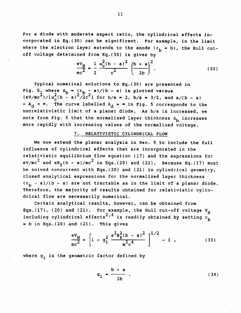
For a diode with moderate aspect ratio, the cylindrical effects in-
corporated in Eq.(30) can be significant. For example, in the limit
where the electron layer extends to the anode (rb - b), the Hull cut-
off voltage determined from Eq.(30) is given by
eV 1 W 2(b - a) 2 b+a2-V _ 2 c 2 (32)inc2 2 c2
Typical numerical solutions to Eq.(30) are presented in
Fig. 5, where Ab - (rb - a)/(b - a) is plotted versus
(eV/mc 2)/wc (b - a)2 /2c 2 for b/a - 2, b/a - 3/2, and a/(b - a)= Ad + m. The curve labelled Ad = O in Fig. 5 corresponds to the
nonrelativistic limit of a planar diode. As b/a is increased, we
note from Fig. 5 that the normalized layer thickness Ab increases
more rapidly with increasing values of the normalized voltage.
7. RELATIVISTIC CYLINDRICAL FLOW
We now extend the planar analysis in Sec. 5 to include the full
influence of cylindrical effects that are incorporated in the
relativistic equilibrium flow equation (17) and the expressions for
eV/mc2 and eBf(b - a)/mc in Eqs.(20) and (21). Because Eq.(17) must
be solved concurrent with Eqs.(20) and (21) in cylindrical geometry,
closed analytical expressions for the normalized layer thickness
(rb - a)/(b - a) are not tractable as in the limit of a planar diode.
Therefore, the majority of results obtained for relativistic cylin-
drical flow are necessarily numerical.
Certain analytical results, however, can be obtained from
Eqs.(17), (20) and (21). For example, the Hull cut-off voltage VHincluding cylindrical effects2, 4 is readily obtained by setting rb= b in Eqs.(20) and (21). This gives
eVH 2e 2B2 (b - a)2 11 / 2
- = 1+ g2 24 -1, (33)mc M c
where g, is the geometric factor defined by
b + a
91 = - (34)2b

12
1.0
0.8- b/a 2 b/a=3/2
0.6-
'Lb -0.4-
- Ad~ C
0.2-
0 0.2 0.4 0.6 0.8 1.0
(eV/mc 2 )/ I W2(b-a) 2 /2c2]
Fig. 5. Plots of the normalized layer thickness A b(rb - a)/(b - a) versus normalized voltage obtained from
Eq.(30) for nonrelativistic electron flow in a cylindrical
diode and several values of b/a.
For V < VH defined in Eq.(33), the electron flow in a cylindrical
diode is magnetically insulated from contact with the anode. In the
limit of a planar diode with (b - a)2 << a 2, the geometric factor g-+ 1 in Eq.(34), and Eq.(33) reduces to the planar result in Eq.(24).
As b/a is increased, however, g, decreases from unity and cylindrical
effects become increasingly important. This is illustrated in Fig. 6
where eVH/mc2 calculated from Eq.(33) is plotted versus the nor-
malized fill field eBf(b - a)/mc2 for several values of b/a and the
geometric factor g, = (b + a)/2b. The curve labeled g, - 1 in Fig. 6
corresponds to the planar limit of a diode with infinite aspect
ratio, i.e., Ad - a/(b - a) -+ - [see Eq.(24) and Fig. 3]. As b/a is
increased and therefore g, is reduced, it is clear from Eq.(33) and
Fig. 6 that cylindrical effects reduce the Hull cut-off voltage
relative to the planar estimate in Eq.(24) and Fig. 3. From Eq.(34),
13
5.0 I
4.0- g1 =
0.9
N 3.0- 0.83
E -0.75
2.I 0.67>2.0-
1.0-
0 . I. . . . .0 1.0 2.0 3.0 4.0 5.0
eBf(b-a)/mc 2
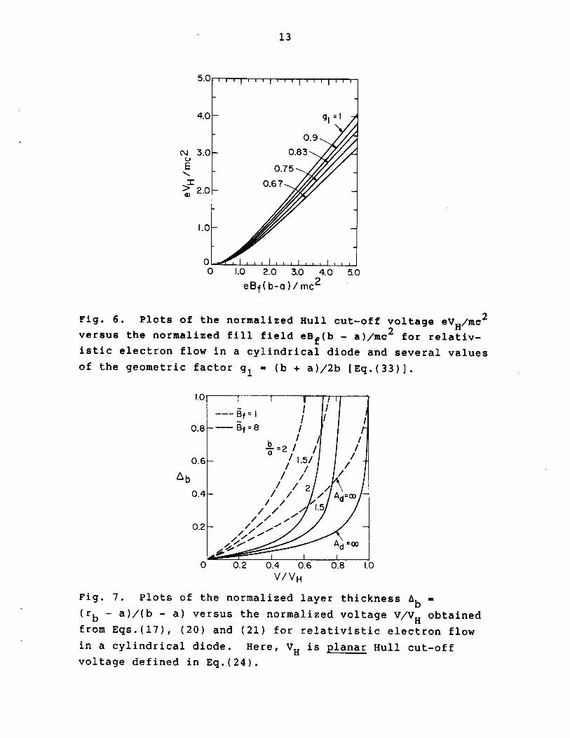
Fig. 6. Plots of the normalized Hull cut-off voltage eVH/mc2
versus the normalized fill field eBf(b - a)/mc2 for relativ-istic electron flow in a cylindrical diode and several valuesof the geometric factor g - (b + a)/2b [Eq.(33)].
1.0 1 1 1
-Bff=80.8 -- Bf 8
b "~2I / /$=2 /
0.6- d- .5/
Ab /2 /0.4- / / / Ad =D
,' '1.5
0.2- Ile
Ad
0 0.2 0.4 0.6 0.8 1.0V/VH
Fig. 7. Plots of the normalized layer thickness Ab(rb - a)/(b - a) versus the normalized voltage V/VH obtained
from Eqs.(17), (20) and (21) for relativistic electron flowin a cylindrical diode. Here, VH is planar Hull cut-offvoltage defined in Eq.(24).

14
this reduction factor is equal to 1 - g2 in the nonrelativistic
regime and equal to 1 - g, in the highly relativistic regime whereeVH/mc2 >> 1. The associated reduction in eVH/mc2 can be substantialfor moderate values of b/a. For example, if b/a - 3, then g - 2/3,
2and 1 - g - 5/9 and 1 - g, - 1/3.
Equations (17), (20) and (21) have been solved numerically todetermine the scaling of the normalized layer thickness ab -
(rb - a)/(b - 2a) with voltage eV/mc2 and fill field f -eBf(b - a)/mc . Typical numerical results are illustrated in Fig. 7,where Ab is plotted versus V/VH for Of - 1 (dashed curves) and §f - 8(solid curves) and b/a - 2, 3/2 and Ad = a/(b - a) 4 -. In Fig. 7,the voltage V is normalized to the relativistic planar Hull cut-offvoltage VH defined in Eq.(24). As in the case of nonrelativistic,cylindrical flow (Fig. 5), the normalized layer thickness ab exhibitsa strong dependence on cylindrical effects as measured by b/a. More-over, for each case presented in Fig. 7, ab approaches unity wheneverV approaches the relativistic cylindrical Hull cut-off voltage VHdefined in Eq.(33). Evidently, when relativistic effects are strong
(the 9 = 8 case in Fig. 7), Ab approaches unity more abruptly thanwhen the flow is nonrelativistic (compare with Fig. 5).
8. CONCLUSIONS
A macroscopic cold-fluid model has been used to determine the
influence of cylindrical effects on the operating range and prop-
erties of the electron flow in relativistic smooth-bore magnetrons.
Assuming operation at Brillouin flow [Eq.(9)], it is found that
cylindrical effects can significantly modify several features of the
equilibrium flow and diode operating range relative to the case of
planar flow. For example, centrifugal effects reduce the radial
electric field (and therefore the Hull cut-off voltage VH) requiredto fill the cathode-anode gap with rb - b (see Fig. 6]. The normal-ized layer thickness Ab - (rb - a)/(b - a) has been calculated over a
wide range of system parameters b/a, eV/mc2 and eBf(b - a)/mc 2
(Fig. 7].
9. ACKNOWLEDGMENTS
This research was supported by the Innovative Science and
Technology Office of SDIO and managed by Harry Diamond Laboratories.

15
10. REFERENCES
1. J. Benford, in High-Power Microwave Sources, edited by V.
Granatstein and I. Alexeff (Artech House, 1987), Chapter 10.
2. Y.Y. Lau, in High-Power Microwave Sources, edited by V.
Granatstein and I. Alexeff (Artech House, 1987), Chapter 9.
3. A. Palevsky, G. Bekefi and A.T. Drobot, J. Appl. Phys. 52, 4938
(1981).
4. A. Palevsky and G. Bekefi, Phys. Fluids 22, 986 (1979).
5. T.J. Orzechowski and G. Bekefi, Phys. Fluids 22, 978 (1979).
6. G. Bekefi and T.J. Orzechowski, Phys. Rev. Lett. 37, 379 (1976).
7. T.M. Antonsen, Jr. and E. Ott, Phys. Fluids 19, 52 (1976).
8. E. Ott and R.V. Lovelace, Appl. Phys. Lett. 27, 378 (1975).
9. C.L. Chang, E. Ott and T.M. Antonsen, Jr., Phys. Fluids 29, 3851
(1986).
10. R.C. Davidson and K.T. Tsang, Phys. Fluids 28, 1169 (1985).
11. R.C. Davidson, K.T. Tsang and J.A. Swegle, Phys. Fluids 27, 2332
(1984).
12. C.L. Chang, T.M. Antonsen, Jr., E. Ott and A.T. Drobot, Phys.
Fluids 27, 2545 (1984).
13. J. Swegle and E. Ott, Phys. Fluids 24, 1821 (1981).
14. K.T. Tsang and R.C. Davidson, Phys. Rev. A33, 4284 (1986).
15. R.C. Davidson and K.T. Tsang, Phys. Fluids 29, 3832 (1986).
16. D. Chernin and Y.Y. Lau, Phys. Fluids 27, 2319 (1984).
17. 0. Buneman, in Cross-Field Microwave Devices, edited by E.
Okress (Academic, New York, 1961), Vol. 1, p. 209.