
Stimulated Brillouin Scattering Phase Conjugate Mirror...
27
12 Stimulated Brillouin Scattering Phase Conjugate Mirror and its Application to Coherent Beam Combined Laser System Producing a High Energy, High Power, High Beam Quality, and High Repetition Rate Output Hong Jin Kong, Seong Ku Lee 1 , Jin Woo Yoon 1 , Jae Sung Shin, and Sangwoo Park Department of Physics, Korea Advanced Institute of Science and Technology 1 Advanced Photonics Research Institute, Gwangju Institute of Science and Technology Republic of Korea 1. Introduction Stimulated Brillouin scattering (SBS) is a nonlinear optical process that generates backward scattered phase conjugate wave (Zel’dovich et al., 1972; Zel’dovich et al., 1985; Damzen et al., 2003; Brignon & Huignard, 2004). A device that generates the phase conjugate wave by the SBS process is called SBS phase conjugate mirror (PCM). An SBS-PCM can compensate wavefront distortion induced by a phase aberrator, such as a laser gain medium; hence, it is widely used in high-energy laser systems to obtain a high-quality beam. Efficient heat dissipation is a major issue in high-energy laser systems, particularly with regard to the high repetition rate. The combination of beams from small laser systems is a constructive approach to this issue. Of the various beam combined systems using SBS-PCMs, the cross- type beam combined system has many outstanding advantages, such as perfect isolation of leak beam, compensation of thermal birefringence, easy alignment and convenient maintenance (Kong et al., 1997, 2005a). Since the SBS wave generates from a thermal noise, it naturally has a random phase with respect to the incident beam. Therefore the phase controlling of the SBS wave is a key technology in the realization of a coherent beam combined system. For this reason, the self-phase control method was proposed and has been developed by Kong et al. (2005a, 2005b, 2005c), which can control the phase of the SBS wave with the simplest composition as well as ease of alignment, no limitations on the number of combined beams, and excellent phase conjugation. Furthermore, the active phase control with a piezoelectric translator (PZT) enables long-term phase stabilization (Kong et al., 2006, 2008). In addition to a random phase characteristic, the distortion that generally occurs in a pulse waveform of an SBS wave is another negative characteristic in terms of the beam combination. Kong et al. (2005d) has overcome this problem with the SBS waveform preservation technique, which is called the prepulse injection method. These works are expected to boost the development of laser systems in term of a high level of energy and Source: Advances in Lasers and Electro Optics, Book edited by: Nelson Costa and Adolfo Cartaxo, ISBN 978-953-307-088-9, pp. 838, April 2010, INTECH, Croatia, downloaded from SCIYO.COM www.intechopen.com
Transcript of Stimulated Brillouin Scattering Phase Conjugate Mirror...
12
Stimulated Brillouin Scattering Phase Conjugate Mirror and its Application to Coherent Beam
Combined Laser System Producing a High Energy, High Power, High Beam Quality,
and High Repetition Rate Output
Hong Jin Kong, Seong Ku Lee1, Jin Woo Yoon1, Jae Sung Shin, and Sangwoo Park
Department of Physics, Korea Advanced Institute of Science and Technology 1Advanced Photonics Research Institute, Gwangju Institute of Science and Technology
Republic of Korea
1. Introduction
Stimulated Brillouin scattering (SBS) is a nonlinear optical process that generates backward scattered phase conjugate wave (Zel’dovich et al., 1972; Zel’dovich et al., 1985; Damzen et al., 2003; Brignon & Huignard, 2004). A device that generates the phase conjugate wave by the SBS process is called SBS phase conjugate mirror (PCM). An SBS-PCM can compensate wavefront distortion induced by a phase aberrator, such as a laser gain medium; hence, it is widely used in high-energy laser systems to obtain a high-quality beam. Efficient heat dissipation is a major issue in high-energy laser systems, particularly with regard to the high repetition rate. The combination of beams from small laser systems is a constructive approach to this issue. Of the various beam combined systems using SBS-PCMs, the cross-type beam combined system has many outstanding advantages, such as perfect isolation of leak beam, compensation of thermal birefringence, easy alignment and convenient maintenance (Kong et al., 1997, 2005a). Since the SBS wave generates from a thermal noise, it naturally has a random phase with respect to the incident beam. Therefore the phase controlling of the SBS wave is a key technology in the realization of a coherent beam combined system. For this reason, the self-phase control method was proposed and has been developed by Kong et al. (2005a, 2005b, 2005c), which can control the phase of the SBS wave with the simplest composition as well as ease of alignment, no limitations on the number of combined beams, and excellent phase conjugation. Furthermore, the active phase control with a piezoelectric translator (PZT) enables long-term phase stabilization (Kong et al., 2006, 2008). In addition to a random phase characteristic, the distortion that generally occurs in a pulse waveform of an SBS wave is another negative characteristic in terms of the beam combination. Kong et al. (2005d) has overcome this problem with the SBS waveform preservation technique, which is called the prepulse injection method. These works are expected to boost the development of laser systems in term of a high level of energy and
Source: Advances in Lasers and Electro Optics, Book edited by: Nelson Costa and Adolfo Cartaxo, ISBN 978-953-307-088-9, pp. 838, April 2010, INTECH, Croatia, downloaded from SCIYO.COM
www.intechopen.com
Advances in Lasers and Electro Optics
230
power, a high-quality beam, and a high repetition rate. A laser system with these characteristics has tremendous potential in the fields such as laser machining, particle accelerators, neutron or proton generators, military weapons, and laser fusion drivers.
2. Stimulated Brillouin scattering phase conjugate mirror
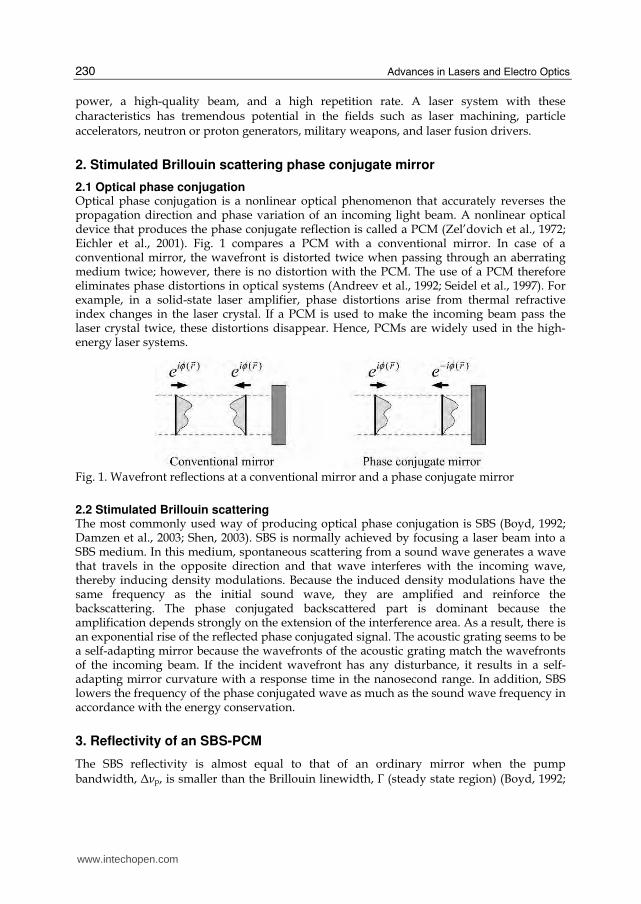
2.1 Optical phase conjugation Optical phase conjugation is a nonlinear optical phenomenon that accurately reverses the propagation direction and phase variation of an incoming light beam. A nonlinear optical device that produces the phase conjugate reflection is called a PCM (Zel’dovich et al., 1972; Eichler et al., 2001). Fig. 1 compares a PCM with a conventional mirror. In case of a conventional mirror, the wavefront is distorted twice when passing through an aberrating medium twice; however, there is no distortion with the PCM. The use of a PCM therefore eliminates phase distortions in optical systems (Andreev et al., 1992; Seidel et al., 1997). For example, in a solid-state laser amplifier, phase distortions arise from thermal refractive index changes in the laser crystal. If a PCM is used to make the incoming beam pass the laser crystal twice, these distortions disappear. Hence, PCMs are widely used in the high-energy laser systems.
Fig. 1. Wavefront reflections at a conventional mirror and a phase conjugate mirror
2.2 Stimulated Brillouin scattering The most commonly used way of producing optical phase conjugation is SBS (Boyd, 1992; Damzen et al., 2003; Shen, 2003). SBS is normally achieved by focusing a laser beam into a SBS medium. In this medium, spontaneous scattering from a sound wave generates a wave that travels in the opposite direction and that wave interferes with the incoming wave, thereby inducing density modulations. Because the induced density modulations have the same frequency as the initial sound wave, they are amplified and reinforce the backscattering. The phase conjugated backscattered part is dominant because the amplification depends strongly on the extension of the interference area. As a result, there is an exponential rise of the reflected phase conjugated signal. The acoustic grating seems to be a self-adapting mirror because the wavefronts of the acoustic grating match the wavefronts of the incoming beam. If the incident wavefront has any disturbance, it results in a self-adapting mirror curvature with a response time in the nanosecond range. In addition, SBS lowers the frequency of the phase conjugated wave as much as the sound wave frequency in accordance with the energy conservation.
3. Reflectivity of an SBS-PCM
The SBS reflectivity is almost equal to that of an ordinary mirror when the pump bandwidth, Δνp, is smaller than the Brillouin linewidth, Г (steady state region) (Boyd, 1992;
www.intechopen.com
Stimulated Brillouin Scattering Phase Conjugate Mirror and its Application to Coherent Beam Combined Laser System Producing a High Energy, High Power, High Beam Quality, and High Repetition Rate Output
231
Yoshida et al., 1997). However, many SBS-PCM applications necessarily involve a broadband pumped SBS (transient region) because laser systems that use an SBS-PCM usually have a broadband spectrum to obtain high output power and short pulse widths (Dane et al., 1995; Králiková et al., 2000). Several theoretical and experimental investigations have reported on the use of a broadband pump in the SBS reflectivity. For a broadband pump, the SBS reflectivity depends on the relation between four parameters: the coherence length, lc; the characteristic interaction length, z0, which is usually equal to the Rayleigh range; the mode spacing, Ωm; and the Brillouin linewidth, Г. When the coherence length is longer than the interaction length (lc > z0), the SBS gain for the broadband pump is as high as the coherence length for the narrowband pump (Narum et al., 1986; D’yakov, 1970; Filippo & Perrone, 1992). Furthermore, if the pump laser mode spacing exceeds the Brillouin linewidth (Ωm>Г), regardless of the mode structure, the SBS gain is the same as that of a single longitudinal mode pump (Narum et al., 1986). Moreover, even if Ωm< Г, the off-resonant acoustic waves, which are generated by the beating between the pump laser mode and another Stokes mode, play an important role in enhancing the gain and the reflectivity (Mullen et al., 1987; Bullock et al., 1994). In all the previously mentioned works, however, the influence of the multimode pump was considered only for two or several longitudinal modes and low pump energy near the SBS threshold. For this reason, the characteristics of SBS reflectivity by a multimode pump with numerous modes and high energy have been investigated (Lee et al., 2005; Kong et al., 2005a).
Liquid Γ
(MHz) Bg
(cm/GW) 2n
(10-22 m2/V2) cP
(MW) bE
(mJ)
Fluorinert FC-75 350 4.5-5 0.34 7.0 6
Carbon tetrachloride (CCl4) 528 3.8 5.9 0.4 1.7
Acetone 119 15.8 8.6 0.28 1.5 Carbon disulfide (CS2) 50 68 122 0.020 0.1
Table 1. Properties of the liquids used for the reflectivity experiments; Г, Brillouin line-width; gB, steady state SBS gain; n2, nonlinear refractive index; Pc, critical power for self-focusing (calculated); Eb, breakdown threshold energy (measured).
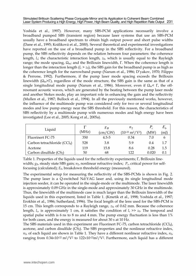
The experimental setup for measuring the reflectivity of the SBS-PCMs is shown in Fig. 2. The pump laser is a Q-switched Nd:YAG laser and, using its single longitudinal mode injection seeder, it can be operated in the single-mode or the multimode. The laser linewidth is approximately 0.09 GHz in the single-mode and approximately 30 GHz in the multimode. Thus, the linewidth of the multimode case is much larger than the Brillouin linewidth of the liquids used in this experiment, listed in Table 1. (Kmetik et al., 1998; Yoshida et al., 1997; Erokhin et al., 1986; Sutherland, 1996). The focal length of the lens used for the SBS-PCM is 15 cm. This length corresponds to a Rayleigh range, z0, of 0.62 mm. Because the coherence length, lc, is approximately 1 cm, it satisfies the condition of lc >> z0. The temporal and spatial pulse width is 6 ns to 8 ns and 4 mm. The pump energy fluctuation is less than 1% for both cases, and the energy is measured for about 30 s at 10 Hz. The SBS materials used in this experiment are Fluorinert FC-75, carbon tetrachloride (CCl4), acetone, and carbon disulfide (CS2). The SBS properties and the nonlinear refractive index, n2, of each liquid are shown in Table 1. They have a different nonlinear refractive index, n2,
ranging from 0.34×10⁻²² m2/V2 to 122×10-22m2/V2. Furthermore, each liquid has a different
www.intechopen.com
Advances in Lasers and Electro Optics
232
Fig. 2. Experimental setup for the measurement of the SBS reflectivity; λ/2, half wave plate;
Pol, polarizer; M, mirror; ND, neutral density filter; λ/4, quarter wave plate; PBS, polarizing beam splitter; BS, beam splitter; PD, photodiode
Brillouin linewidth, ranging from 50 MHz to 528 MHz. The breakdown threshold, Eb, which
is listed in Table 1, was measured when a bright spark appeared inside the SBS cell.
Figs. 3(a) and 3(b) show the SBS reflectivity for the single-mode and the multimode cases of
CCl4 and Fluorinert FC-75 as a function of the pump energy. Note that CCl4 and FC-75 have
a very similar SBS gain and Brillouin linewidth (see Table 1), which results in a similar
reflectivity curve of typical nonlinear variation for the single-mode pump. For the
multimode pump, the SBS reflectivity is different for each of the liquids. The fact that the
SBS threshold for both pump modes is approximately the same regardless of the liquids
indicates that the SBS gain for the multimode pump is as high as that for the single-mode
pump in both liquids The peak reflectivity is 30% in CCl4 and more than 65% in FC-75,
though the reflectivity decreases as the pump energy increases. Note also that even though
the single-mode pump generally has a higher SBS gain (Valley, 1986; Arecchi, 1972), the SBS
reflectivity in CCl4 is slightly higher for the multimode pump than for the single-mode
pump near the SBS threshold of the single-mode case. For FC-75, on the other hand, the
behavior is exactly the opposite.
Several factors appear to contribute to the reflectivity difference of the multimode pump.
We interpret the SBS reflectivity for the multimode pump in terms of the temporal intensity
spikes of the multimode pulse, which are absent in the single-mode pulse. A beating
between a large numbers of longitudinal mode brings the intensity spikes to rise, and the
intensity spikes have enough power to induce nonlinear effects, such as self-focusing and
the optical breakdown. The self-focusing that is caused by the intensity spikes is likely to
lead to an anomalously high reflectivity of the multimode pump near the SBS threshold in
CCl4. The critical power of the self-focusing is given by
3
2
2
oc
cP
n
πε
ω= , (1)
www.intechopen.com
Stimulated Brillouin Scattering Phase Conjugate Mirror and its Application to Coherent Beam Combined Laser System Producing a High Energy, High Power, High Beam Quality, and High Repetition Rate Output
233
(a) (b)
(c) (d)
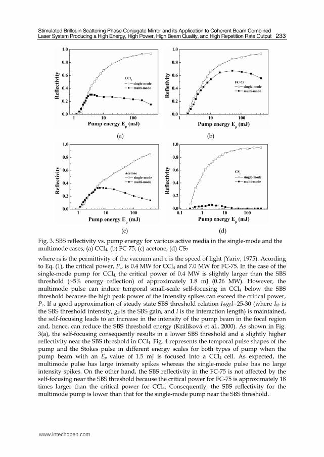
Fig. 3. SBS reflectivity vs. pump energy for various active media in the single-mode and the multimode cases; (a) CCl4; (b) FC-75; (c) acetone; (d) CS2
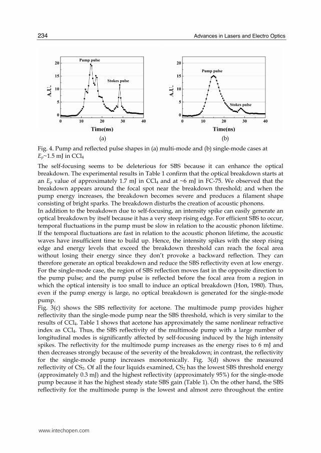
where ε0 is the permittivity of the vacuum and c is the speed of light (Yariv, 1975). Acording to Eq. (1), the critical power, Pc, is 0.4 MW for CCl4 and 7.0 MW for FC-75. In the case of the single-mode pump for CCl4, the critical power of 0.4 MW is slightly larger than the SBS threshold (~5% energy reflection) of approximately 1.8 mJ (0.26 MW). However, the multimode pulse can induce temporal small-scale self-focusing in CCl4 below the SBS threshold because the high peak power of the intensity spikes can exceed the critical power, Pc. If a good approximation of steady state SBS threshold relation IthgBl=25-30 (where Ith is the SBS threshold intensity, gB is the SBS gain, and l is the interaction length) is maintained, the self-focusing leads to an increase in the intensity of the pump beam in the focal region and, hence, can reduce the SBS threshold energy (Králiková et al., 2000). As shown in Fig. 3(a), the self-focusing consequently results in a lower SBS threshold and a slightly higher reflectivity near the SBS threshold in CCl4. Fig. 4 represents the temporal pulse shapes of the pump and the Stokes pulse in different energy scales for both types of pump when the pump beam with an Ep value of 1.5 mJ is focused into a CCl4 cell. As expected, the multimode pulse has large intensity spikes whereas the single-mode pulse has no large intensity spikes. On the other hand, the SBS reflectivity in the FC-75 is not affected by the self-focusing near the SBS threshold because the critical power for FC-75 is approximately 18 times larger than the critical power for CCl4. Consequently, the SBS reflectivity for the multimode pump is lower than that for the single-mode pump near the SBS threshold.
www.intechopen.com
Advances in Lasers and Electro Optics
234
(a) (b)
Fig. 4. Pump and reflected pulse shapes in (a) multi-mode and (b) single-mode cases at Ep~1.5 mJ in CCl4
The self-focusing seems to be deleterious for SBS because it can enhance the optical breakdown. The experimental results in Table 1 confirm that the optical breakdown starts at an Ep value of approximately 1.7 mJ in CCl4 and at ~6 mJ in FC-75. We observed that the breakdown appears around the focal spot near the breakdown threshold; and when the pump energy increases, the breakdown becomes severe and produces a filament shape consisting of bright sparks. The breakdown disturbs the creation of acoustic phonons. In addition to the breakdown due to self-focusing, an intensity spike can easily generate an optical breakdown by itself because it has a very steep rising edge. For efficient SBS to occur, temporal fluctuations in the pump must be slow in relation to the acoustic phonon lifetime. If the temporal fluctuations are fast in relation to the acoustic phonon lifetime, the acoustic waves have insufficient time to build up. Hence, the intensity spikes with the steep rising edge and energy levels that exceed the breakdown threshold can reach the focal area without losing their energy since they don’t provoke a backward reflection. They can therefore generate an optical breakdown and reduce the SBS reflectivity even at low energy. For the single-mode case, the region of SBS reflection moves fast in the opposite direction to the pump pulse; and the pump pulse is reflected before the focal area from a region in which the optical intensity is too small to induce an optical breakdown (Hon, 1980). Thus, even if the pump energy is large, no optical breakdown is generated for the single-mode pump. Fig. 3(c) shows the SBS reflectivity for acetone. The multimode pump provides higher reflectivity than the single-mode pump near the SBS threshold, which is very similar to the results of CCl4. Table 1 shows that acetone has approximately the same nonlinear refractive index as CCl4. Thus, the SBS reflectivity of the multimode pump with a large number of longitudinal modes is significantly affected by self-focusing induced by the high intensity spikes. The reflectivity for the multimode pump increases as the energy rises to 6 mJ and then decreases strongly because of the severity of the breakdown; in contrast, the reflectivity for the single-mode pump increases monotonically. Fig. 3(d) shows the measured reflectivity of CS2. Of all the four liquids examined, CS2 has the lowest SBS threshold energy (approximately 0.3 mJ) and the highest reflectivity (approximately 95%) for the single-mode pump because it has the highest steady state SBS gain (Table 1). On the other hand, the SBS reflectivity for the multimode pump is the lowest and almost zero throughout the entire
www.intechopen.com
Stimulated Brillouin Scattering Phase Conjugate Mirror and its Application to Coherent Beam Combined Laser System Producing a High Energy, High Power, High Beam Quality, and High Repetition Rate Output
235
region. The critical power (20 KW) for the self-focusing is about half the SBS threshold (40 KW). Furthermore, CS2 has the longest acoustic lifetime (6 ns) of the liquids used (Erokhin et al., 1986), and this life-span is comparable to the pulse-width of the pump beam. As already mentioned, if the temporal fluctuations of the pump pulse are fast in relation to the acoustic phonon lifetime, the acoustic waves lack sufficient time to build up. As a result, CS2 has a lower breakdown threshold (approximately 0.1 mJ) than the SBS threshold, and this very low threshold can account for the almost zero reflectivity observed. We observed that the optical breakdown produces a filament if the pump energy is almost as weak as the SBS threshold. Note that the stimulated Raman scattering (SRS) may be also responsible for the low reflectivity. CS2 has a high SRS gain. The very short response time of the SRS process (10-11 s) implies that the SRS response to the intensity spikes of the multimode pulse is better than that of the SBS process (Linde et al., 1969).
4. The cross-type double-pass laser amplifier with symmetric SBS-PCMs
Kong et al. proposed a cross-type double-pass laser amplifier with symmetric SBS-PCMs.
(Kong et al., 1998; Kong et al., 2001) Fig. 5 shows the conceptual layout. In this section, the
noteworthy advantages of the cross-type amplifier with SBS-PCMs will be examined,
particularly the use of the threshold of SBS-PCM to attain perfect isolation of the leak beam,
the compensation of thermally induced birefringence (TIB), and the alignment-free
property.
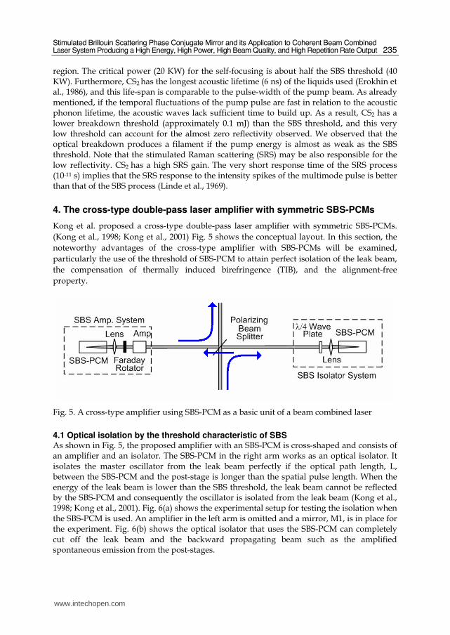
Fig. 5. A cross-type amplifier using SBS-PCM as a basic unit of a beam combined laser
4.1 Optical isolation by the threshold characteristic of SBS As shown in Fig. 5, the proposed amplifier with an SBS-PCM is cross-shaped and consists of an amplifier and an isolator. The SBS-PCM in the right arm works as an optical isolator. It isolates the master oscillator from the leak beam perfectly if the optical path length, L, between the SBS-PCM and the post-stage is longer than the spatial pulse length. When the energy of the leak beam is lower than the SBS threshold, the leak beam cannot be reflected by the SBS-PCM and consequently the oscillator is isolated from the leak beam (Kong et al., 1998; Kong et al., 2001). Fig. 6(a) shows the experimental setup for testing the isolation when the SBS-PCM is used. An amplifier in the left arm is omitted and a mirror, M1, is in place for the experiment. Fig. 6(b) shows the optical isolator that uses the SBS-PCM can completely cut off the leak beam and the backward propagating beam such as the amplified spontaneous emission from the post-stages.
www.intechopen.com
Advances in Lasers and Electro Optics
236
(a) (b)
Fig. 6. (a) Schematic of the experimental set up: P1 & P2, polarizer; FR, Faraday rotator; PE, pyro-electric energy meter; QWP1 & QWP2, quarter-wave-plate; L1, lens; PBS, polarizing beam splitter; M1, conventional mirror. (b) Leak beam energy dependence on the optical path length L.
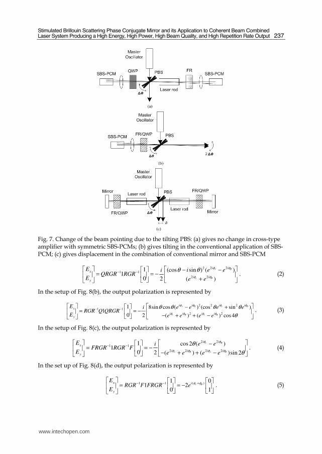
4.2 Alignment-free optical system The principle of the isolator that uses SBS-PCMs was explained in the previous section. However, the fact that an additional arm uses SBS-PCMs implies that the system has an alignment-free characteristic, which is one of the advantages of the cross-type amplifier system with SBS-PCMs. As shown in Fig. 7, although other systems such as the systems shown in Figs. 7(b) and 7(c) change the beam pointing due to the misalignment of the polarizing beam splitter, the suggested system of Fig. 7(a) has no effect on the beam direction or the beam position. Thus, the beam pointing of the output has the same level as the input (the master oscillator). The insensitivity to the misalignment and tilting of any optical components relies on the fact that the beam reflected by SBS-PCM follows exactly the same path as the incoming beam on account of the phase-conjugate characteristics.
4.3 Compensation for the thermal birefringence in the amplifier medium Diminishment of the thermal load and the related thermal effects, particularly the compensation for TIB, is a traditional and important topic in the high-energy laser field. As shown in Fig. 8, the amplifying part of a cross-type amplifier with an SBS-PCM has three components: an amplifier rod, a polarization rotator (such as a Faraday rotator or a quarter-wave-plate), and an SBS-PCM (SBS cell and focusing optics). The total system has four available configurations, which are shown in Figs. 8(a) to 8(d). As in similar situations (Han & Kong, 1995), the theoretical prediction of TIB compensation can be given by Jones
matrices. When we use the matrix elements of the Faraday rotator, 1 11
1 12F
⎡ ⎤= ⎢ ⎥−⎣ ⎦ , the
quarter-wave-plate, 1
1
iQ
i
⎡ ⎤= ⎢ ⎥⎣ ⎦ , the glass rod, 0
0
ri
i
eG
e θ
φ
φ
⎡ ⎤= ⎢ ⎥⎣ ⎦ , and the rotation matrix,
cos sin
sin cosR
θ θ
θ θ
⎡ ⎤= ⎢ ⎥−⎣ ⎦ , the output after a double-pass amplification, x
y
E
E
⎡ ⎤⎢ ⎥⎣ ⎦ , can be calculated. In
the setup of Fig. 8(a), the output polarization is represented by
www.intechopen.com
Stimulated Brillouin Scattering Phase Conjugate Mirror and its Application to Coherent Beam Combined Laser System Producing a High Energy, High Power, High Beam Quality, and High Repetition Rate Output
237
Fig. 7. Change of the beam pointing due to the tilting PBS: (a) gives no change in cross-type amplifier with symmetric SBS-PCMs; (b) gives tilting in the conventional application of SBS-PCM; (c) gives displacement in the combination of conventional mirror and SBS-PCM
222
1 1
22
1 (cos sin ) ( )1
0 2 ( )
r
r
iix
iiy
E i e eiQRGR RGR
E e e
θ
θ
φφ
φφ
θ θ− −⎡ ⎤ ⎡ ⎤⎡ ⎤ − −
= = −⎢ ⎥ ⎢ ⎥⎢ ⎥+⎣ ⎦ ⎣ ⎦⎣ ⎦ . (2)
In the setup of Fig. 8(b), the output polarization is represented by
2 2 2
1 1
2 2
1 8sin cos ( ) (cos sin )1
0 2 ( ) ( ) cos 4
r r
r r
i ii ix
i ii iy
E e e e eiRGR Q QRGR
E e e e e
θ θ
θ θ
φ φϕ φ
φ φφ φ
θ θ θ θ
θ− −
⎡ ⎤ ⎡ ⎤⎡ ⎤ − += = −⎢ ⎥ ⎢ ⎥⎢ ⎥
− + + −⎣ ⎦ ⎣ ⎦⎣ ⎦ . (3)
In the setup of Fig. 8(c), the output polarization is represented by
22
1 1
2 22 2
1 cos 2 ( )1
0 2 ( ) ( )sin 2
r
r r
iix
i ii iy
E e eiFRGR RGR F
E e e e e
θ
θ θ
φφ
φ φφ φ
θ
θ− −
⎡ ⎤ ⎡ ⎤⎡ ⎤ −= = −⎢ ⎥ ⎢ ⎥⎢ ⎥
− + + −⎣ ⎦ ⎣ ⎦⎣ ⎦ . (4)
In the set up of Fig. 8(d), the output polarization is represented by
( )1 11 0
1 20 1
rx i
y
ERGR F FRGR e
Eθφ φ+− −
⎡ ⎤ ⎡ ⎤ ⎡ ⎤= = −⎢ ⎥ ⎢ ⎥ ⎢ ⎥⎣ ⎦ ⎣ ⎦⎣ ⎦ . (5)
www.intechopen.com
Advances in Lasers and Electro Optics
238
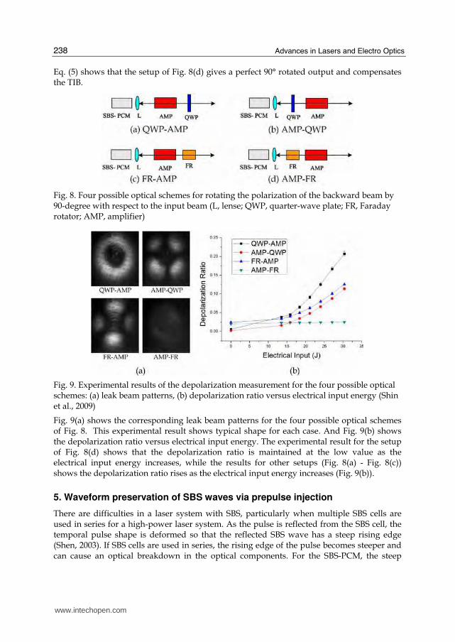
Eq. (5) shows that the setup of Fig. 8(d) gives a perfect 90° rotated output and compensates the TIB.
Fig. 8. Four possible optical schemes for rotating the polarization of the backward beam by 90-degree with respect to the input beam (L, lense; QWP, quarter-wave plate; FR, Faraday rotator; AMP, amplifier)
Fig. 9. Experimental results of the depolarization measurement for the four possible optical schemes: (a) leak beam patterns, (b) depolarization ratio versus electrical input energy (Shin et al., 2009)
Fig. 9(a) shows the corresponding leak beam patterns for the four possible optical schemes of Fig. 8. This experimental result shows typical shape for each case. And Fig. 9(b) shows the depolarization ratio versus electrical input energy. The experimental result for the setup of Fig. 8(d) shows that the depolarization ratio is maintained at the low value as the electrical input energy increases, while the results for other setups (Fig. 8(a) - Fig. 8(c)) shows the depolarization ratio rises as the electrical input energy increases (Fig. 9(b)).
5. Waveform preservation of SBS waves via prepulse injection
There are difficulties in a laser system with SBS, particularly when multiple SBS cells are used in series for a high-power laser system. As the pulse is reflected from the SBS cell, the temporal pulse shape is deformed so that the reflected SBS wave has a steep rising edge (Shen, 2003). If SBS cells are used in series, the rising edge of the pulse becomes steeper and can cause an optical breakdown in the optical components. For the SBS-PCM, the steep
www.intechopen.com
Stimulated Brillouin Scattering Phase Conjugate Mirror and its Application to Coherent Beam Combined Laser System Producing a High Energy, High Power, High Beam Quality, and High Repetition Rate Output
239
rising edge leads to low reflectivity and low fidelity of the phase conjugated wave in the SBS medium (Dane et al., 1992). Thus, a suitable technique is needed to preserve the temporal waveform of the reflected SBS wave (Kong et al., 2005d).
(a) (b)
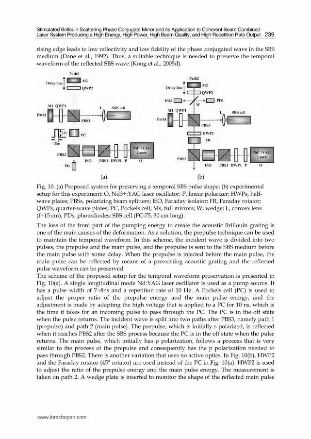
Fig. 10. (a) Proposed system for preserving a temporal SBS pulse shape; (b) experimental setup for this experiment: O, Nd3+:YAG laser oscillator; P, linear polarizer; HWPs, half-wave plates; PBSs, polarizing beam splitters; ISO, Faraday isolator; FR, Faraday rotator; QWPs, quarter-wave plates; PC, Pockels cell; Ms, full mirrors; W, wedge; L, convex lens (f=15 cm); PDs, photodiodes; SBS cell (FC-75, 30 cm long).
The loss of the front part of the pumping energy to create the acoustic Brillouin grating is one of the main causes of the deformation. As a solution, the prepulse technique can be used to maintain the temporal waveform. In this scheme, the incident wave is divided into two pulses, the prepulse and the main pulse, and the prepulse is sent to the SBS medium before the main pulse with some delay. When the prepulse is injected before the main pulse, the main pulse can be reflected by means of a preexisting acoustic grating and the reflected pulse waveform can be preserved. The scheme of the proposed setup for the temporal waveform preservation is presented in Fig. 10(a). A single longitudinal mode Nd:YAG laser oscillator is used as a pump source. It has a pulse width of 7~8ns and a repetition rate of 10 Hz. A Pockels cell (PC) is used to adjust the proper ratio of the prepulse energy and the main pulse energy, and the adjustment is made by adapting the high voltage that is applied to a PC for 10 ns, which is the time it takes for an incoming pulse to pass through the PC. The PC is in the off state when the pulse returns. The incident wave is split into two paths after PBS3, namely path 1 (prepulse) and path 2 (main pulse). The prepulse, which is initially s polarized, is reflected when it reaches PBS2 after the SBS process because the PC is in the off state when the pulse returns. The main pulse, which initially has p polarization, follows a process that is very similar to the process of the prepulse and consequently has the p polarization needed to pass through PBS2. There is another variation that uses no active optics. In Fig. 10(b), HWP2 and the Faraday rotator (45° rotator) are used instead of the PC in Fig. 10(a). HWP2 is used to adjust the ratio of the prepulse energy and the main pulse energy. The measurement is taken on path 2. A wedge plate is inserted to monitor the shape of the reflected main pulse
www.intechopen.com
Advances in Lasers and Electro Optics
240
and the incoming main pulse waveform and the reflected SBS waveform are obtained. The delay is modulated by the movable mirror, and the FC-75 fluid is used as the SBS medium.
Fig. 11. Incident and reflected waveforms with the prepulse injection; (a) Epre = 0 mJ, (b) Epre = 2 mJ, (c) Epre = 2.5mJ, (d) Epre ≥ 3mJ for values of Tdelay = 8 ns and Emain = 10 mJ.
Let us define Emain as the energy of the main pulse, Epre as the energy of the prepulse, and
Tdelay as the delay between the prepulse and the main pulse. Fig. 11 shows the waveform
measured for values of Tdelay = 8 ns and Emain = 10 mJ. As Epre increases, the temporal
waveforms of the reflected wave become similar to that of the incident wave. When Epre
exceeds 3 mJ, the experimental data have very similar aspects as the case of Epre = 3 mJ. This
similarity implies that if we set the prepulse energy equal to or larger than 3 mJ with a delay
of 8 ns, the main pulse need not consume its own energy to build the acoustic grating.
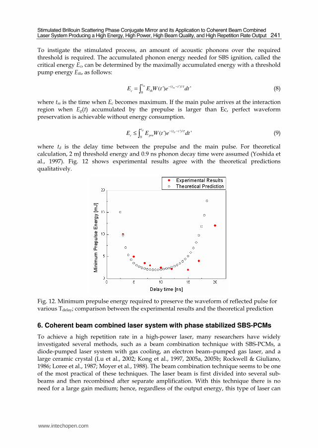
Fig. 12 shows the minimum prepulse energy required to preserve the waveform of reflected
pulse for various Tdelay (Yoon et al., 2009). For small Tdelay, the main pulse arrives so early
that a part of the main pulse energy can play a role in building the acoustic grating, because
the integrated energy of the prepulse is insufficient to generate the grating before the main
pulse arrives. Therefore the energy required to preserve the waveform of the main pulse is
higher than the moderate Tdelay. For large Tdelay, most of the acoustic grating disappears
before the main pulse arrives at the SBS interaction region so that more energy is required to
preserve the waveform.
A theoretical calculation that describes these experimental results was formulated using a
simple model. If the pump pulse is focused in the SBS medium, acoustic phonons are
generated and then accumulated in the focal area. Considering the phonon decay, the pump
pulse energy transferred to acoustic phonons and accumulated by time t, Eg(t), is given by
( ') /
0( ) ( ') '
tt t
gE t P t e dt
τ− −= ∫ (6)
where P(t) is the temporal pulse shape and τ is the phonon lifetime. If the pulse width is independent of the pulse energy, the temporal pulse shape can be represented as
( ) ( )P t E W t= ⋅ (7)
where E is the pulse energy, and W(t) is the normalized waveform.
www.intechopen.com
Stimulated Brillouin Scattering Phase Conjugate Mirror and its Application to Coherent Beam Combined Laser System Producing a High Energy, High Power, High Beam Quality, and High Repetition Rate Output
241
To instigate the stimulated process, an amount of acoustic phonons over the required threshold is required. The accumulated phonon energy needed for SBS ignition, called the critical energy Ec, can be determined by the maximally accumulated energy with a threshold pump energy Eth, as follows:
( ') /
0( ') '
mm
tt t
c thE E W t e dt
τ− −= ∫ (8)
where tm is the time when Ec becomes maximum. If the main pulse arrives at the interaction region when Eg(t) accumulated by the prepulse is larger than Ec, perfect waveform preservation is achievable without energy consumption.
( ') /
0( ') '
dd
tt t
c preE E W t e dtτ− −≤ ∫ (9)
where td is the delay time between the prepulse and the main pulse. For theoretical calculation, 2 mJ threshold energy and 0.9 ns phonon decay time were assumed (Yoshida et al., 1997). Fig. 12 shows experimental results agree with the theoretical predictions qualitatively.
Fig. 12. Minimum prepulse energy required to preserve the waveform of reflected pulse for various Tdelay; comparison between the experimental results and the theoretical prediction
6. Coherent beam combined laser system with phase stabilized SBS-PCMs
To achieve a high repetition rate in a high-power laser, many researchers have widely investigated several methods, such as a beam combination technique with SBS-PCMs, a diode-pumped laser system with gas cooling, an electron beam–pumped gas laser, and a large ceramic crystal (Lu et al., 2002; Kong et al., 1997, 2005a, 2005b; Rockwell & Giuliano, 1986; Loree et al., 1987; Moyer et al., 1988). The beam combination technique seems to be one of the most practical of these techniques. The laser beam is first divided into several sub-beams and then recombined after separate amplification. With this technique there is no need for a large gain medium; hence, regardless of the output energy, this type of laser can
www.intechopen.com
Advances in Lasers and Electro Optics
242
operate at a repetition rate exceeding 10 Hz and can be easily adapted to modern laser technology. However, with conventional SBS-PCMs, the SBS waves have random initial phases because they are generated by noises. For this reason, the phase locking of the SBS wave is strongly required for the output of a coherent beam combination.
6.1 Phase control of the SBS wave by means of the self-generated density modulation There have been several successful works in the history of the phase locking of SBS waves
(Rockwell & Giuliano, 1986; Loree et al., 1987; Moyer et al., 1988). Although these works
show good phase locking effects, they have some problems in terms of the practical
application of a multiple beam combination. In the overlapping method, all the beams are
focused on one common point. The energy scaling is therefore limited to avoid an optical
breakdown, and the optical alignment is also difficult. In the back-seeding beam method,
the phase conjugation is incomplete if the injected Stokes beam is not completely correlated.
Kong et al. (2005a, 2005b, 2005c) proposed a new phase control technique involving self-
generated density modulation. In this method, which is simply called the self-phase control
method, a simple optical composition is used with a single concave mirror behind the SBS
cell; furthermore, each beam phase can be independently and easily controlled without
destruction of the phase conjugation. Thus, the phase control method obviates the need for
any structural limitation on the energy scaling.
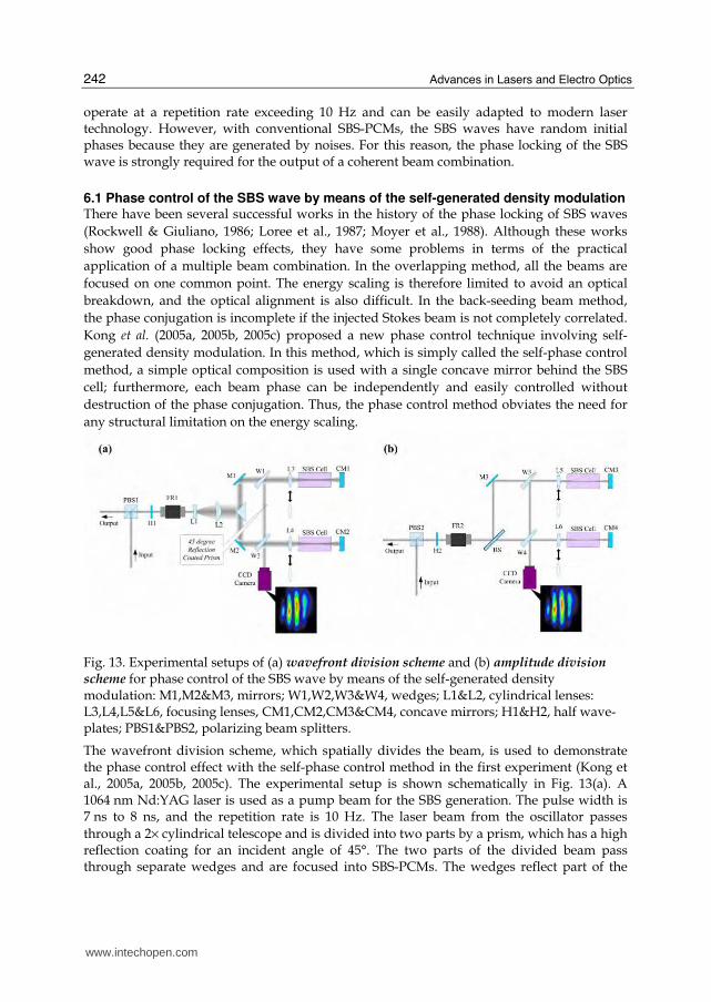
Fig. 13. Experimental setups of (a) wavefront division scheme and (b) amplitude division scheme for phase control of the SBS wave by means of the self-generated density modulation: M1,M2&M3, mirrors; W1,W2,W3&W4, wedges; L1&L2, cylindrical lenses: L3,L4,L5&L6, focusing lenses, CM1,CM2,CM3&CM4, concave mirrors; H1&H2, half wave-plates; PBS1&PBS2, polarizing beam splitters.
The wavefront division scheme, which spatially divides the beam, is used to demonstrate the phase control effect with the self-phase control method in the first experiment (Kong et al., 2005a, 2005b, 2005c). The experimental setup is shown schematically in Fig. 13(a). A 1064 nm Nd:YAG laser is used as a pump beam for the SBS generation. The pulse width is 7 ns to 8 ns, and the repetition rate is 10 Hz. The laser beam from the oscillator passes
through a 2× cylindrical telescope and is divided into two parts by a prism, which has a high reflection coating for an incident angle of 45°. The two parts of the divided beam pass through separate wedges and are focused into SBS-PCMs. The wedges reflect part of the
www.intechopen.com
Stimulated Brillouin Scattering Phase Conjugate Mirror and its Application to Coherent Beam Combined Laser System Producing a High Energy, High Power, High Beam Quality, and High Repetition Rate Output
243
backward Stokes beams so that they are overlapped onto a CCD camera. Then, the interference pattern of them is generated. The degree of the fluctuation of the relative phase difference between the SBS waves is quantitatively analyzed by measuring the movement of the peaks in the interference pattern. For the case of the wavefront division, the divided sub-pump beams get fluctuating energies for every shot due to the beam pointing effect of the laser source, which seems to generate the fluctuation of the relative phase difference between the SBS waves, because the phase of the SBS wave depends on the pump energy. This beam pointing problem can be overcome by using an amplitude division method, whereby the sub-pump beams have almost the same level of energy (Lee et al., 2005). The experimental setup of the amplitude division scheme is shown in Fig. 13(b). In the amplitude division scheme, the laser beam from an oscillator is divided into two sub-beams by a beam splitter (BS).
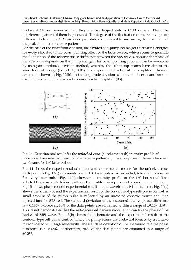
Fig. 14. Experimental result for the unlocked case: (a) schematic; (b) intensity profile of horizontal lines selected from 160 interference patterns; (c) relative phase difference between two beams for 160 laser pulses.
Fig. 14 shows the experimental schematic and experimental results for the unlocked case.
Each point in Fig. 14(c) represents one of 160 laser pulses. As expected, δ has random value for every laser pulse. Fig. 14(b) shows the intensity profile of the 160 horizontal lines selected from each interference pattern. The profile also represents the random fluctuation. Fig 15 shows phase control experimental results in the wavefront division scheme. Fig. 15(a)
shows the schematic and the experimental result of the concentric-type self-phase control. A
small amount of the pump pulse is reflected by an uncoated concave mirror and then
injected into the SBS cell. The standard deviation of the measured relative phase difference
is ~ 0.165λ. Moreover, 88% of the data points are contained within a range of ±0.25λ (±90°).
This result demonstrates that the self-generated density modulation can fix the phase of the
backward SBS wave. Fig. 15(b) shows the schematic and the experimental result of the
confocal-type self-phase control, where the pump beams are backward focused by a concave
mirror coated with high reflectivity. The standard deviation of the measured relative phase
difference is ~ 0.135λ. Furthermore, 96% of the data points are contained in a range of
±0.25λ.
www.intechopen.com
Advances in Lasers and Electro Optics
244
Fig. 15. Phase control experimental results in the wavefront division scheme, with (a) concentric-type self-phase control ((left-up) schematic, (left-down) intensity profile of horizontal lines from interference pattern, (right) relative phase difference between two beams for 203 laser pulses) and (b) confocal-type self-phase control ((left-up) schematic, (left-down) intensity profile of horizontal lines from interference pattern, (right) relative phase difference between two beams for 238 laser pulses).
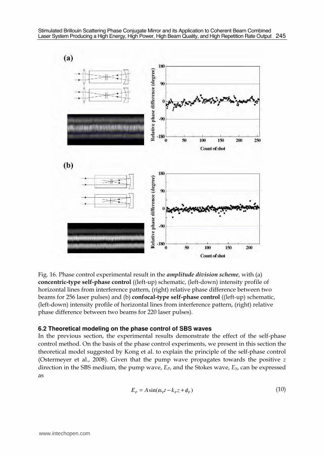
Fig. 16 shows phase control experimental results in the amplitude division scheme. Fig. 16(a) shows the schematic and the experimental result of the concentric-type self-phase
control. The standard deviation of the measured relative phase difference is ~ 0.0366λ. And Fig. 16(b) shows the schematic and the experimental result of the confocal-type self-phase
control. The standard deviation of the measured relative phase difference is ~ 0.0275λ. By employing the amplitude division scheme, the relative phase difference is remarkably stabilized compared with the wavefront dividing scheme.
www.intechopen.com
Stimulated Brillouin Scattering Phase Conjugate Mirror and its Application to Coherent Beam Combined Laser System Producing a High Energy, High Power, High Beam Quality, and High Repetition Rate Output
245
Fig. 16. Phase control experimental result in the amplitude division scheme, with (a) concentric-type self-phase control ((left-up) schematic, (left-down) intensity profile of horizontal lines from interference pattern, (right) relative phase difference between two beams for 256 laser pulses) and (b) confocal-type self-phase control ((left-up) schematic, (left-down) intensity profile of horizontal lines from interference pattern, (right) relative phase difference between two beams for 220 laser pulses).
6.2 Theoretical modeling on the phase control of SBS waves In the previous section, the experimental results demonstrate the effect of the self-phase
control method. On the basis of the phase control experiments, we present in this section the
theoretical model suggested by Kong et al. to explain the principle of the self-phase control
(Ostermeyer et al., 2008). Given that the pump wave propagates towards the positive z
direction in the SBS medium, the pump wave, EP, and the Stokes wave, ES, can be expressed
as
)sin( PPPP zktAE φω +−= (10)
www.intechopen.com
Advances in Lasers and Electro Optics
246
and
sin( )ω φ= + +S S S SE B t k z , (11)
where A and B are the amplitudes of EP and ES; ω, k and φ are the angular frequency, the
wave number and the initial phase, respectively; and P and S are the pump wave and the Stokes wave, respectively. The density modulation of the SBS medium is proportional to the total electrical field. The density modulation, ┩, can therefore be represented as
2 2 2 2 2sin ( ) sin ( )
cos[( ) ( ) ( )]
cos[( ) ( ) ( )].
P S P P P S S S
P S P S P S
P S P S P S
E E A t k z B t k z
AB t k k z
AB t k k z
ρ ω φ ω φ
ω ω φ φ
ω ω φ φ
∝ + = − + + + +
− + − − + +
+ − − + + −
(12)
Only the final term of Eq. (12) can contribute to the acoustic wave because the first two terms are DC components and the third term denotes the fast oscillating components. The acoustic wave can be also expressed as
0 cos( )a at k zρ ρ φ= Ω + + , (13)
where ┩0 is the mean value of the medium density and Ω, ka, and aφ are the frequency, the
wave number, and the initial phase of the acoustic wave, respectively. From Eqs. (12) and
(13), the relations of P Sω ωΩ = − , = +a P Sk k k and a P Sφ φ φ= − can be obtained. If aφ and Pφ
are known values, Sφ can be definitely determined in accordance with the phase relation. If the acoustic wave is assumed to be initially generated at time t0 and position z0, the acoustic wave can be rewritten as
)]()(cos[ 000 zzktt a −−−Ω= ρρ
]cos[ 000 zktzkt aa +Ω−−Ω= ρ . (14)
The phase of the acoustic wave is then given by
0 0a at k zφ = −Ω + . (15)
In conventional SBS generation, t0 and z0 have random values as the SBS wave is generated from a thermal acoustic noise. However, t0 and z0 can be locked effectively by the proposed self-phase control method.
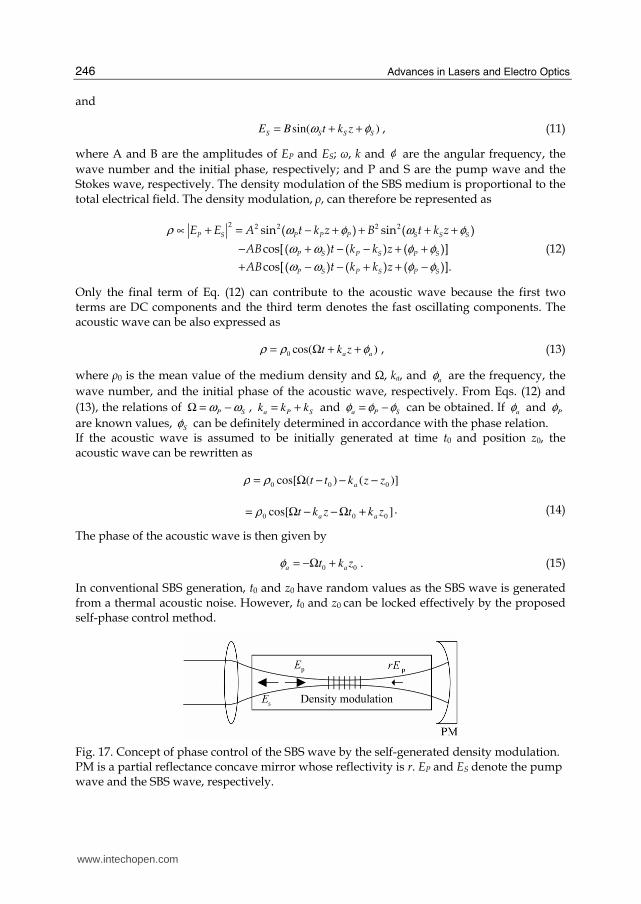
Fig. 17. Concept of phase control of the SBS wave by the self-generated density modulation. PM is a partial reflectance concave mirror whose reflectivity is r. EP and ES denote the pump wave and the SBS wave, respectively.
www.intechopen.com
Stimulated Brillouin Scattering Phase Conjugate Mirror and its Application to Coherent Beam Combined Laser System Producing a High Energy, High Power, High Beam Quality, and High Repetition Rate Output
247
Fig. 17 describes the concept of the self-phase control method. The weak periodic density modulation is generated at the focal point due to the electrostriction by an electromagnetic standing wave that arises from the interference between the main beam, EP, and the low intensity counter-propagating beam, rEP. In the suggested theoretical model, the weak density modulation from the standing wave is assumed to act as an imprint for the ignition of the Brillouin grating. Hence, the initial position, z0, is no longer random but fixed to one of the nodal points of the density modulation. However, there are many candidates of the nodal points in the Rayleigh range because the Rayleigh length, lR, is much larger than the period of the stationary density modulation, λP/2, where λP is the wavelength of the pump wave. The phase differences between the acoustic waves generated at different nodal points have the values of NNk Paa πλφ 2)2/( ≅=Δ ( N : integer) for the relation of
PPa kk λπ /42 =≅ .
Thus, the phase uncertainty of 2┨N does not affect the phase accuracy. The initial time, t0, when the acoustic wave is determined should be known. In the research on the preservation of the SBS waveform (Kong et al., 2005d), the front part of the pump energy is consumed to create the acoustic Brillouin grating of the SBS process. This consumed energy is regarded as the SBS threshold energy. The critical time, tc, when the SBS is initiated can then be determined by the following equation:
c
th
0
( )
t
E P t dt= ∫ , (16)
where Eth is the SBS threshold energy of the SBS medium and )(tP is the pump power. It is
assumed that t0 is equal to tc because the SBS waves and the corresponding acoustic wave
are generated simultaneously. Eq. (16) suggests suggests that the initial ignition time, t0, of
the acoustic wave changes if the total energy of the pump pulse given by ∫∞
=0
0 )( dttPE
changes under a constant pulse width. In this model, the critical time, tc, varies with the total
energy, E0. Thus, the change that occurs in the initial phase, 0φΔ , as a result of the energy
fluctuation, 0EΔ , can be represented as
c 00 c 0
0 0
t Et E
E Eφ
Δ ΔΔ = ΩΔ = Ω
Δ (17)
if we assume that z0 is fixed; 0φΔ can be calculated numerically for FC-75, which has an
acoustic wave frequency of 1.34 GHz; and the SBS threshold is about 2 mJ for a 10 ns pulse.
Let‘s assume that the pump pulse, P(t), is given by
2 203
4( ) exp[ ( / ) ]
EP t t t a
a π= − ( 8.66ns)a = . (18)
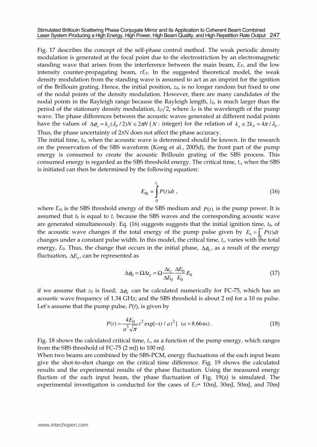
Fig. 18 shows the calculated critical time, tc, as a function of the pump energy, which ranges from the SBS threshold of FC-75 (2 mJ) to 100 mJ. When two beams are combined by the SBS-PCM, energy fluctuations of the each input beam give the shot-to-shot change on the critical time difference. Fig. 19 shows the calculated results and the experimental results of the phase fluctuation. Using the measured energy fluction of the each input beam, the phase fluctuation of Fig. 19(a) is simulated. The experimental investigation is conducted for the cases of E1= 10mJ, 30mJ, 50mJ, and 70mJ
www.intechopen.com
Advances in Lasers and Electro Optics
248
with several E2 values. In both graphs, the standard deviation of the relative phase fluctuation is shown. The shapes of the graphs are similar but the vertical scales are different.
0 20 40 60 80 100
3
6
9
12
15
Cri
tica
l ti
me
(tc)
(ns)
Pump energy (Et) (mJ)
Fig. 18. Critical time tc as a function of the pump energy (Eth=2mJ).
0 20 40 60 80 1000.00λ
0.01λ
0.02λ
0.03λ
0.04λ
0.05λ
0.06λ
E1=10mJ
E1=30mJ
E1=50mJ
E1=70mJ
Pha
se
flu
ctu
ation
E2 (mJ)
0 20 40 60 80 1000.00λ
0.10λ
0.20λ
0.30λ
0.40λ
0.50λ
0.60λ
E1=10mJ
E1=30mJ
E1=50mJ
E1=70mJ
Ph
ase
flu
ctu
ation
E2 (mJ)
(a) (b)
Fig. 19. (a) Calculated results of the relative phase difference for the cases of E1 = 10 mJ, 30 mJ, 50 mJ, and 70 mJ with E2 = 2 mJ to 100mJ; the critical time is calculated directly from the energy measurements. (b) Experimental results of the relative phase difference for the cases of E1 = 10 mJ, 30 mJ, 50 mJ, and 70 mJ with several E2 values.
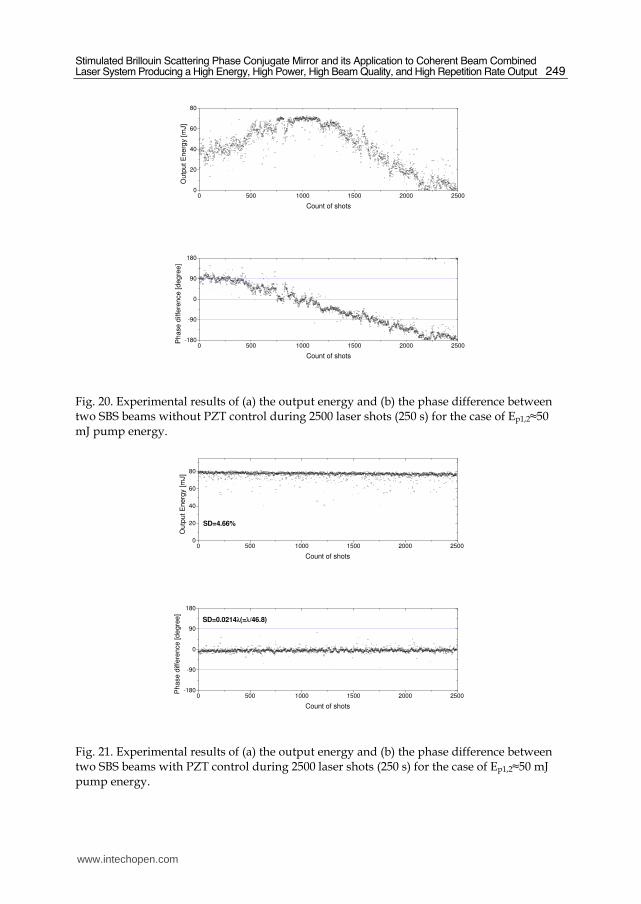
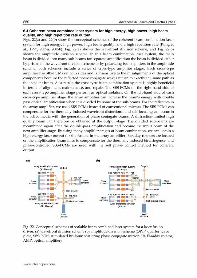
6.3 Long-term phase stabilization of SBS wave The self-phase control method ensures the SBS wave is well stabilized for several hundred shots. However, a thermally induced long-term phase fluctuation occurs when the number of laser shots increases (Kong et al., 2006, 2008). This slowly varying phase fluctuation can be easily compensated through the active control of PZTs attached to one concave mirror of the SBS-PCM. Figs. 20 and 21 show the phase control experimental results for the cases with PZT control and without PZT control, respectively, in a two-beam combination system. The phase difference and the output energy are measured during 2500 laser shots (250 s) for a pump energy level of Ep1,2≈50 mJ. The case without PZT control showed long-term phase and output energy fluctuations. In the case with the PZT control, the phase difference between the SBS beams is well stabilized with a fluctuation of 0.0214λ(=λ/46.8) by standard deviation; furthermore, the output energy is stabilized with a fluctuation of 4.66%.
www.intechopen.com
Stimulated Brillouin Scattering Phase Conjugate Mirror and its Application to Coherent Beam Combined Laser System Producing a High Energy, High Power, High Beam Quality, and High Repetition Rate Output
249
0 500 1000 1500 2000 25000
20
40
60
80
Ou
tpu
t E
ne
rgy [
mJ]
Count of shots
0 500 1000 1500 2000 2500-180
-90
0
90
180
Ph
ase
diffe
ren
ce
[d
eg
ree
]
Count of shots
Fig. 20. Experimental results of (a) the output energy and (b) the phase difference between two SBS beams without PZT control during 2500 laser shots (250 s) for the case of Ep1,2≈50 mJ pump energy.
0 500 1000 1500 2000 25000
20
40
60
80
Ou
tput E
ne
rgy [m
J]
Count of shots
SD=4.66%
0 500 1000 1500 2000 2500-180
-90
0
90
180
SD=0.0214λ(=λ/46.8)
Pha
se
diffe
ren
ce
[d
eg
ree
]
Count of shots
Fig. 21. Experimental results of (a) the output energy and (b) the phase difference between two SBS beams with PZT control during 2500 laser shots (250 s) for the case of Ep1,2≈50 mJ pump energy.
www.intechopen.com
Advances in Lasers and Electro Optics
250
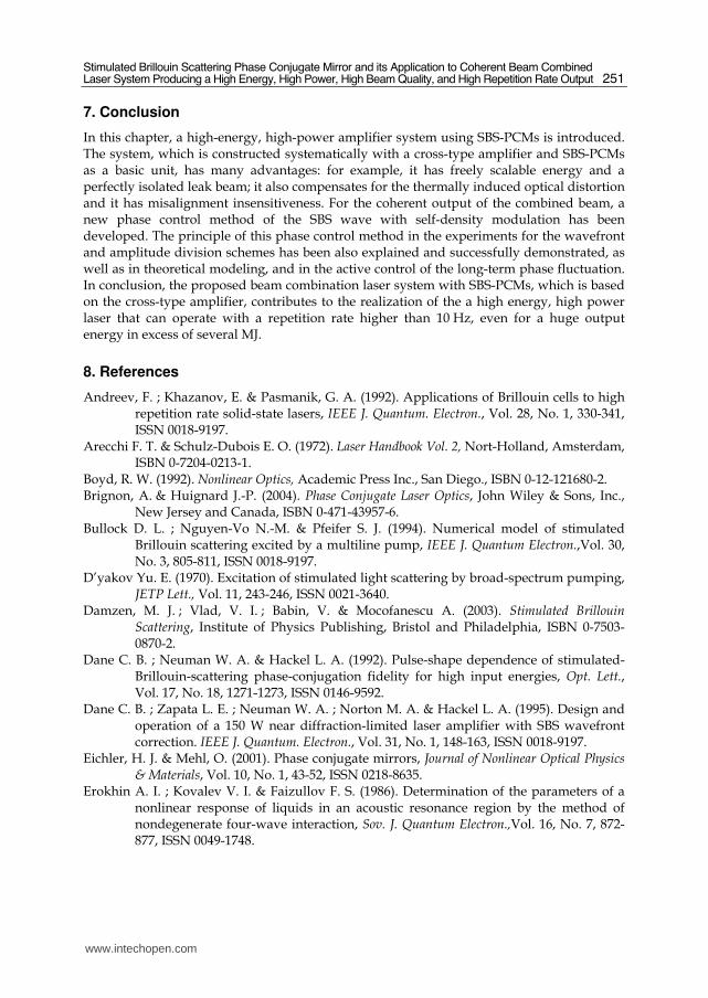
6.4 Coherent beam combined laser system for high energy, high power, high beam quality, and high repetition rate output Figs. 22(a) and 22(b) show the conceptual schemes of the coherent beam combination laser
system for high energy, high power, high beam quality, and a high repetition rate (Kong et
al., 1997, 2005a, 2005b). Fig. 22(a) shows the wavefront division scheme, and Fig. 22(b)
shows the amplitude division scheme. In this beam combination laser system, the main
beam is divided into many sub-beams for separate amplification; the beam is divided either
by prisms in the wavefront division scheme or by polarizing beam splitters in the amplitude
scheme. Both schemes include a series of cross-type amplifier stages. Each cross-type
amplifier has SBS-PCMs on both sides and is insensitive to the misalignments of the optical
components because the reflected phase conjugate waves return to exactly the same path as
the incident beam. As a result, the cross-type beam combination system is highly beneficial
in terms of alignment, maintenance, and repair. The SBS-PCMs on the right-hand side of
each cross-type amplifier stage perform as optical isolators. On the left-hand side of each
cross-type amplifier stage, the array amplifier can increase the beam’s energy with double
pass optical amplification when it is divided by some of the sub-beams. For the reflectors in
the array amplifier, we used SBS-PCMs instead of conventional mirrors. The SBS-PCMs can
compensate for the thermally induced wavefront distortions, and self-focusing can occur in
the active media with the generation of phase conjugate beams. A diffraction-limited high
quality beam can therefore be obtained at the output stage. The divided sub-beams are
recombined again after the double-pass amplification and become the input beam of the
next amplifier stage. By using many amplifier stages of beam combination, we can obtain a
high-energy laser output for the fusion. In the array amplifier, Faraday rotators are located
on the amplification beam lines to compensate for the thermally induced birefringence, and
phase-controlled SBS-PCMs are used with the self phase control method for coherent
output.
Fig. 22. Conceptual schemes of scalable beam combined laser system for a laser fusion driver: (a) wavefront division scheme (b) amplitude division scheme (QWP, quarter wave plate; SBS-PCM, stimulated Brillouin scattering phase conjugate mirror, FR, Faraday rotator; AMP, optical amplifier)
www.intechopen.com
Stimulated Brillouin Scattering Phase Conjugate Mirror and its Application to Coherent Beam Combined Laser System Producing a High Energy, High Power, High Beam Quality, and High Repetition Rate Output
251
7. Conclusion
In this chapter, a high-energy, high-power amplifier system using SBS-PCMs is introduced. The system, which is constructed systematically with a cross-type amplifier and SBS-PCMs as a basic unit, has many advantages: for example, it has freely scalable energy and a perfectly isolated leak beam; it also compensates for the thermally induced optical distortion and it has misalignment insensitiveness. For the coherent output of the combined beam, a new phase control method of the SBS wave with self-density modulation has been developed. The principle of this phase control method in the experiments for the wavefront and amplitude division schemes has been also explained and successfully demonstrated, as well as in theoretical modeling, and in the active control of the long-term phase fluctuation. In conclusion, the proposed beam combination laser system with SBS-PCMs, which is based on the cross-type amplifier, contributes to the realization of the a high energy, high power laser that can operate with a repetition rate higher than 10 Hz, even for a huge output energy in excess of several MJ.
8. References
Andreev, F. ; Khazanov, E. & Pasmanik, G. A. (1992). Applications of Brillouin cells to high repetition rate solid-state lasers, IEEE J. Quantum. Electron., Vol. 28, No. 1, 330-341, ISSN 0018-9197.
Arecchi F. T. & Schulz-Dubois E. O. (1972). Laser Handbook Vol. 2, Nort-Holland, Amsterdam, ISBN 0-7204-0213-1.
Boyd, R. W. (1992). Nonlinear Optics, Academic Press Inc., San Diego., ISBN 0-12-121680-2. Brignon, A. & Huignard J.-P. (2004). Phase Conjugate Laser Optics, John Wiley & Sons, Inc.,
New Jersey and Canada, ISBN 0-471-43957-6. Bullock D. L. ; Nguyen-Vo N.-M. & Pfeifer S. J. (1994). Numerical model of stimulated
Brillouin scattering excited by a multiline pump, IEEE J. Quantum Electron.,Vol. 30, No. 3, 805-811, ISSN 0018-9197.
D’yakov Yu. E. (1970). Excitation of stimulated light scattering by broad-spectrum pumping, JETP Lett., Vol. 11, 243-246, ISSN 0021-3640.
Damzen, M. J. ; Vlad, V. I. ; Babin, V. & Mocofanescu A. (2003). Stimulated Brillouin Scattering, Institute of Physics Publishing, Bristol and Philadelphia, ISBN 0-7503-0870-2.
Dane C. B. ; Neuman W. A. & Hackel L. A. (1992). Pulse-shape dependence of stimulated-Brillouin-scattering phase-conjugation fidelity for high input energies, Opt. Lett., Vol. 17, No. 18, 1271-1273, ISSN 0146-9592.
Dane C. B. ; Zapata L. E. ; Neuman W. A. ; Norton M. A. & Hackel L. A. (1995). Design and operation of a 150 W near diffraction-limited laser amplifier with SBS wavefront correction. IEEE J. Quantum. Electron., Vol. 31, No. 1, 148-163, ISSN 0018-9197.
Eichler, H. J. & Mehl, O. (2001). Phase conjugate mirrors, Journal of Nonlinear Optical Physics & Materials, Vol. 10, No. 1, 43-52, ISSN 0218-8635.
Erokhin A. I. ; Kovalev V. I. & Faizullov F. S. (1986). Determination of the parameters of a nonlinear response of liquids in an acoustic resonance region by the method of nondegenerate four-wave interaction, Sov. J. Quantum Electron.,Vol. 16, No. 7, 872-877, ISSN 0049-1748.
www.intechopen.com
Advances in Lasers and Electro Optics
252
Filippo A. A. & Perrone M. R. (1992). Experimental study of stimulated Brillouin scattering by broad-band pumping, IEEE J. Quantum Electron., Vol. 28, No. 9, 1859-1863, ISSN 0018-9197.
Han, K.G. & Kong, H.J. (1995). Four-pass amplifier system compensation thermally induced birefringence effect using a novel dumping mechanism, Jpn. J. Appl. Phys, Vol. 34, Part 2, No. 8A, 994–996, ISSN 0021-4922.
Hon, D. T. (1980). Pulse compression by stimulated Brillouin scattering, Opt. Lett., Vol. 5, No.12 516-518, ISSN 0146-9592.
Kmetik, V. ; Fiedorowicz, H. ; Andreev, A. A. ; Witte, K. J. ; Daido H. ; Fujita H. ; Nakatsuka M. & Yamanaka T. (1998). Reliable stimulated Brillouin scattering compression of Nd:YAG laser pulses with liquid fluorocarbon for long-time operation at 10 Hz, Appl. Opt., Vol. 37, No. 30, 7085-7090, ISSN 0003-6935.
Kong, H. J. ; Beak, D. H. ; Lee, D. W. & Lee, S. K. (2005d). Waveform preservation of the backscattered stimulated Brillouin scattering wave by using a prepulse injection, Opt. Lett., Vol. 30, No. 24, 3401-3403, ISSN 0146-9592.
Kong, H. J. ; Lee, J. Y. ; Shin, Y. S. ; Byun, J. O. ; Park, H. S. & Kim H. (1997). Beam recombination characteristics in array laser amplification using stimulated Brillouin scattering phase conjugation, Opt. Rev. Vol. 4, No. 2, 277-283, ISSN 1340-6000.
Kong, H. J. ; Lee, S. K. & Lee, D. W. (2005a). Beam combined laser fusion driver with high power and high repetition rate using stimulated Brillouin scattering phase conjugation mirrors and self-phase locking, Laser Part. Beams Vol. 23, 55-59, ISSN 0263-0346.
Kong, H. J. ; Lee, S. K. & Lee, D. W. (2005b). Highly repetitive high energy/power beam combination laser : IFE laser driver using independent phase control of stimulated Brillouin scattering phase conjugate mirrors and pre-pulse technique, Laser Part. Beams Vol. 23, 107-111, ISSN 0263-0346.
Kong, H. J. ; Lee, S. K. ; Lee, D. W. & Guo, H. (2005c). Phase control of a stimulated Brillouin scattering phase conjugate mirror by a self-generated density modulation, Appl. Phys. Lett. Vol. 86, 051111, ISSN 0003-6951.
Kong, H. J. ; Yoon, J. W. ; Shin, J. S. & Beak, D. H. (2008). Long-term stabilized two-beam combination laser amplifier with stimulated Brillouin scattering mirrors, Appl. Phys. Lett. Vol. 92, 021120, ISSN 0003-6951.
Kong, H. J. ; Yoon, J. W. ; Shin, J. S. ; Beak, D. H. & Lee, B. J. (2006). Long term stabilization of the beam combination laser with a phase controlled stimulated Brillouin scattering phase conjugation mirrors for the laser fusion driver, Laser Part. Beams. Vol. 24, 519-523, ISSN 0265-0346.
Kong, H.J.; Kang, Y.G.; Ohkubo, A., Yoshida, H. & Nakatsuka, M. (1998). Complete isolation of the back reflection by using stimulated Brillouin scattering phase conjugation mirror. Review of Laser Engineering, Vol. 26, 138–140, ISSN 0387-0200.
Kong, H.J. ; Lee, S.K.; Kim, J.J.; Kang, Y.G. & Kim. H. (2001). A cross type double pass laser amplifier with two symmetric phase conjugation mirrors using stimulated Brillouin scattering, Chinese Journal of Lasers, Vol. B10, I5-I9, ISSN 1004-2822.
Králiková B. ; Skála J.; Straka P. & Turčičová H. (2000). High-quality phase conjugation even in a highly transient regime of stimulated Brillouin scattering, Appl. Phys. Lett., Vol. 77, 627-629, ISSN 0003-6951.
www.intechopen.com
Stimulated Brillouin Scattering Phase Conjugate Mirror and its Application to Coherent Beam Combined Laser System Producing a High Energy, High Power, High Beam Quality, and High Repetition Rate Output
253
Lee, S. K. ; Kong, H. J. & Nakatsuka, M. (2005). Great improvement of phase controlling of the entirely independent stimulated Brillouin scattering phase conjugate mirrors by balancing the pump energies, Appl. Phys. Lett., Vol. 87, 161109, ISSN 0003-6951.
Linde D. ; Maier M. & Kaiser, W. (1969). Quantitative Investigations of the Stimulated Raman Effect Using Subnanosecond Light Pulses, Phys. Rev., Vol. 178, No. 1, 11-15, ISSN 0031-899X.
Loree T. R. ; Watkins, D. E. ; Johnson, T. M. ; Kurnit, N. A. & Fisher, R. A. (1987). Phase locking two beams by means of seeded Brillouin scattering, Opt. Lett., Vol. 12, No. 3, 178-180, ISSN 0146-9592.
Lu J. ; Lu J. ; Murai, T. ; Takaichi, K. ; Uematsu, T. ; Xu, J. ; Ueda, K. ; Yagi, H. ; Yanagitani, T. & Kaminskii, A. A. (2002). 36-W diode-pumped continuous-wave 1319-nm Nd:YAG ceramic laser, Opt. Lett. Vol. 27, No. 13, 1120-1122, ISSN 0146-9592.
Moyer R. H. ; Valley, M. & Cimolino, M. C. (1988). Beam combination throgh stimulated Brillouin scattering, J. Opt. Soc. Am. B Vol. 5, No. 12, 2473-2489, ISSN 0740-3224.
Mullen R. A.; Lind R. C. & Valley G. C. (1987). Observation of stimulated Brillouin scattering gain with a dual spectral-line pump, Opt. Commun., Vol. 63, No. 2, 123-128, ISSN 0030-4018.
Narum P. ; Skeldon M. D. & Boyd R. W. (1986). Effect of laser mode structure on stimulated Brillouin scattering, IEEE J. Quantum Electron., Vol. 22, No. 11, 2161-2167, ISSN 0018-9197.
Ostermeyer, M. ; Kong H. J. ; Kovalev, V. I. ; Harrison R. G. ; Fotiadi A. A. ; P., Mégret, Kalal, M. ; Slezak, O. ; Yoon, J. W. ; Shin, J. S. ; Beak, D. H. ; Lee, S. K. ; Lü, Z. ; Wang, S. ; Lin, D. ; Knight, J. C. ; Kotova, N. E. ; Sträßer, A. ; Scheikh-Obeid, A. ; Riesbeck, T. ; Meister, S. ; Eichler, H. J. ; Wang, Y. ; He, W. ; Yoshida, H. ; Fujita, H. ; Nakatsuka , M. ; Hatae, T. ; Park, H. ; Lim, C. ; Omatsu, T. ; Nawata K. ; Shiba N. ; Antipov O. L. ; Kuznetsov, M. S. & Zakharov, N. G. (2008). Trends in stimulated Brillouin scattering and optical phase conjugation, Laser Part. Beams Vol. 26, No. 3, 297-362, ISSN 0265-0346.
Shin, J. S.; Park, S. & Kong, H. J. (2009). Compensation of the thermally induced depolarization in a double-pass Nd:YAG rod amplifier with a stimulated Brillouin scattering phase conjugate mirror, to be published.
Rockwell, D. A. & Giuliano, C. R. (1986). Coherent coupling of laser gain media using phase conjugation, Opt. Lett., Vol. 11, 147-149, ISSN 0146-9592.
Seidel, S & Kugler, N. (1997). Nd:YAG 200-W average-power oscillator-amplifier system with stimulated-Brillouin-scattering phase conjugation and depolarization compensation, J. Opt. Soc. Am. B, Vol. 14, No. 7, 1885-1888, ISSN 0740-3224.
Shen Y. R. (2003). Principles of Nonlinear Optics, Wiley, New York, ISBN 0471-88998-9. Sutherland R. L. (1996). Handbook of Nonlinear Optics, Marcel Dekker Inc., New York, ISBN
082-474243-5. Valley G. C. (1986). A review of stimulated Brillouin scattering excited with a broad-band
pump laser. IEEE J. Quantum. Electron., Vol. 22, No. 5, 704-712, ISSN 0018-9197. Yariv, Ammon (1975). Quantum Electronics, John Wiley, New York, ISBN 047-160997-8. Yoon, J. W.; Shin, J. S. ; Kong, H. J. & Lee, J. (2009). Investigation of the relationship between
the prepulse energy and the delay time in the waveform preservation of a stimulated Brillouin scattering wave by prepulse injection, to be published.
www.intechopen.com

Advances in Lasers and Electro Optics
254
Yoshida H.; Kmetik V.; Fujita H.; Nakatsuka M.; Yamanaka T. & Yoshida K. (1997). Heavy fluorocarbon liquids for a phase-conjugated stimulated Brillouin scattering mirror, Appl. Opt., Vol. 36, No. 16, 3739-3744, ISSN 0003-6935.
Zel’dovich, B. Y. ; Popovichev, V. I. ; Ragulsky, V. V. & Faizullov, F. S. (1972). Connection between the wave fronts of the reflected and exciting light in stimulated Mandel' shtem-Brillouin scattering, Sov. Phys. JETP, Vol. 15, 109, ISSN 0038-5646.
Zel’dovich, B. Y. ; Pilipetsky, N. F. & Shkunov, V. V. (1985). Principle of Phase Conjugation, Springer-Verlag, Berlin, Heidelberg, New York and Tokyo, ISBN 3-540-13458-1.
www.intechopen.com
Advances in Lasers and Electro OpticsEdited by Nelson Costa and Adolfo Cartaxo
ISBN 978-953-307-088-9Hard cover, 838 pagesPublisher InTechPublished online 01, April, 2010Published in print edition April, 2010
InTech EuropeUniversity Campus STeP Ri Slavka Krautzeka 83/A 51000 Rijeka, Croatia Phone: +385 (51) 770 447 Fax: +385 (51) 686 166www.intechopen.com
InTech ChinaUnit 405, Office Block, Hotel Equatorial Shanghai No.65, Yan An Road (West), Shanghai, 200040, China
Phone: +86-21-62489820 Fax: +86-21-62489821
Lasers and electro-optics is a field of research leading to constant breakthroughs. Indeed, tremendousadvances have occurred in optical components and systems since the invention of laser in the late 50s, withapplications in almost every imaginable field of science including control, astronomy, medicine,communications, measurements, etc. If we focus on lasers, for example, we find applications in quite differentareas. We find lasers, for instance, in industry, emitting power level of several tens of kilowatts for welding andcutting; in medical applications, emitting power levels from few milliwatt to tens of Watt for various types ofsurgeries; and in optical fibre telecommunication systems, emitting power levels of the order of one milliwatt.This book is divided in four sections. The book presents several physical effects and properties of materialsused in lasers and electro-optics in the first chapter and, in the three remaining chapters, applications of lasersand electro-optics in three different areas are presented.
How to referenceIn order to correctly reference this scholarly work, feel free to copy and paste the following:
Hong Jin Kong, Seong Ku Lee, Jin Woo Yoon, Jae Sung Shin and Sangwoo Park (2010). Stimulated BrillouinScattering Phase Conjugate Mirror and its Application to Coherent Beam Combined Laser System Producing aHigh Energy, High Power, High Beam Quality, and High Repetition Rate Output, Advances in Lasers andElectro Optics, Nelson Costa and Adolfo Cartaxo (Ed.), ISBN: 978-953-307-088-9, InTech, Available from:http://www.intechopen.com/books/advances-in-lasers-and-electro-optics/stimulated-brillouin-scattering-phase-conjugate-mirror-and-its-application-to-coherent-beam-combined
![The Conjugate Gradient Method...Conjugate Gradient Algorithm [Conjugate Gradient Iteration] The positive definite linear system Ax = b is solved by the conjugate gradient method.](https://static.fdocuments.in/doc/165x107/5e95c1e7f0d0d02fb330942a/the-conjugate-gradient-method-conjugate-gradient-algorithm-conjugate-gradient.jpg)