Cybex VR2 Owner’s and Service Manual Strength …...Cybex VR2 Owner’s Manual Hip Adduction -...
230
Cybex VR2 Owner’s and Service Manual Strength Systems Part Number 54599 www.cybexinternational.com
Transcript of Cybex VR2 Owner’s and Service Manual Strength …...Cybex VR2 Owner’s Manual Hip Adduction -...
Cybex VR2Owner’s and Service Manual
Strength SystemsPart Number 54599
www.cybexinternational.com

Cybex VR2Owner’s and Service Manual
Strength SystemsPart Number 54599
DISCLAIMER: Cybex International, Inc., makes no representations or warranties regarding the contents of this manual. We reserve the right torevise this document at any time or to make changes to the product described within it without notice or obligation to notify any person of suchrevisions or changes.© Copyright 1995, 1996, 1997, 1998, 1999, 2000, 2001, 2002, 2003, 2004 Cybex International, Inc. All rights reserved.Printed in the United States of America.10 Trotter Drive Medway, MA 02053 • 508-533-4300 • FAX 508-533-5183 www.cybexinternational.com • [email protected] • [email protected] • 54599 • July 2004

i Table of Contents
1 Technical SpecificationsGeneral Specifications . . . . . . . . . . . 1-1VR2 Machine Specifications . . . . . . . 1-3
2 General Exercise GuidelinesGeneral . . . . . . . . . . . . . . . . . . . . . . . 2-1Glossary . . . . . . . . . . . . . . . . . . . . . . . 2-2Single-Set Exercise ChartMultiple-Set Exercise Chart
3 ExercisesSeated Leg Press - 4605. . . . . . . . . . 3-1Leg Extension - 4611, 4612, 4613 . . 3-5Prone Leg Curl - 4616, 4617, 4618 . . 3-9Seated Leg Curl - 4626 . . . . . . . . . . . 3-13Hip Adduction - 4640 . . . . . . . . . . . . 3-17Hip Abduction - 4645 . . . . . . . . . . . . 3-19Rotary Calf - 4620 . . . . . . . . . . . . . . . 3-21Chest Press - Dual Axis - 4507 . . . . . 3-23Chest Press - Single Axis - 4506. . . . 3-27Incline Press - Dual Axis - 4512 . . . . 3-29Incline Press - Single Axis - 4511 . . . 3-33Pulldown - Dual Axis - 4515 . . . . . . . 3-37Row/Rear Delt - Dual Axis - 4520 . . . 3-41Row/Rear Delt - Single Axis - 4521. . 3-45Overhead Press - Dual Axis - 4527 . . 3-49Overhead Press - Single Axis - 4526. 3-53Lat Pulldown - Single Axis - 4516 . . . 3-55Fly - 4545. . . . . . . . . . . . . . . . . . . . . . 3-57Lateral Raise - 4530. . . . . . . . . . . . . . 3-61Arm Curl - 4535 . . . . . . . . . . . . . . . . . 3-63Arm Extension - 4540 . . . . . . . . . . . . 3-65Ab Crunch - 4705 . . . . . . . . . . . . . . . 3-67Back Extension - 4711, 4712, 4713 . 3-69Torso Rotation - 4715 . . . . . . . . . . . . 3-73
4 Customer ServiceContacting Service . . . . . . . . . . . . . . 4-1Ordering Parts . . . . . . . . . . . . . . . . . . 4-1RMA . . . . . . . . . . . . . . . . . . . . . . . . . . 4-2Damaged Parts . . . . . . . . . . . . . . . . . 4-3
Table of Contents
5 Delivery & InstallationDelivery Inspection . . . . . . . . . . . . . . 5-1Installation . . . . . . . . . . . . . . . . . . . . . 5-1
Anchoring . . . . . . . . . . . . . . . . . . . . 5-2Safety. . . . . . . . . . . . . . . . . . . . . . . . 5-2Weight Stack Installation Instructions
6 MaintenanceDaily Procedures . . . . . . . . . . . . . . . . 6-1Weekly Procedures . . . . . . . . . . . . . . 6-3Yearly Procedures . . . . . . . . . . . . . . . 6-5“As Required” Procedures. . . . . . . . . 6-5
7 ServiceGrip and Belt Replacement . . . . . . . . 7-1Belt Removal . . . . . . . . . . . . . . . . . . . 7-3Belt Installation . . . . . . . . . . . . . . . . . 7-3Grip Replacement . . . . . . . . . . . . . . . 7-5Pivot Shaft Removal . . . . . . . . . . . . . 7-6Pivot Shaft Installation . . . . . . . . . . . 7-6Chest Press - Single Axis . . . . . . . . . 4506Chest Press - Dual Axis . . . . . . . . . . 4507Incline Press - Single Axis . . . . . . . . . 4511Incline Press - Dual Axis . . . . . . . . . . 4512Pulldown - Dual Axis . . . . . . . . . . . . . 4515Lat Pulldown - Single Axis. . . . . . . . . 4516Row/Rear Delt - Dual Axis. . . . . . . . . 4520Row/Rear Delt - Single Axis . . . . . . . 4521Overhead Press - Single Axis . . . . . . 4526Overhead Press - Dual Axis . . . . . . . 4527Lateral Raise . . . . . . . . . . . . . . . . . . . 4530Arm Curl. . . . . . . . . . . . . . . . . . . . . . . 4535Arm Extension . . . . . . . . . . . . . . . . . . 4540Seated Leg Press . . . . . . . . . . . . . . . 4605Leg Extension . . . . . . . 4611, 4612, 4613Prone Leg Curl . . . . . . . 4616, 4617, 4618Rotary Calf . . . . . . . . . . . . . . . . . . . . . 4620Seated Leg Curl . . . . . . . . . . . . . . . . . 4626Hip Adduction . . . . . . . . . . . . . . . . . . 4640Hip Abduction . . . . . . . . . . . . . . . . . . 4645Ab Crunch . . . . . . . . . . . . . . . . . . . . . 4705Back Extension . . . . . . . 4711, 4712, 4713Torso Rotation . . . . . . . . . . . . . . . . . . 4715
Page i

Frame Finish
• Shall be made of mechanical quality 11-gauge steel purchased in mill run quantities to assure the best consistency.
• Prior to applying finish, each part shall be put through a multi-stage wash to remove all oils and to chemically prepare the surface for maximum adhesion. After the wash, the frames shall be dried and coated with an Electrostatically applied powdercoat finish that shall be applied in powder form and then baked until cured.
• The finish shall be textured and very hard, assuring a scratch and chip resistant finish.
Weight Selection
• Weights are to be selected by using a high quality selector pin that completely penetrates the weight plate and locks in place to eliminate any chance of disengaging the pin during use. The pin shall be attached to the weight stack with a plastic lanyard in order that the pin stays with the appropriate machine. All weights shall be selected while the user is in position on/in the machine to allow adjustment of the resistance from the exercise position.
Weight Stack Configuration
• All weight stacks shall have 12 1/2-pound weights except for the Standing Calf Raise (Product No. 4875) which shall have 20 pound weight plates.
Increment Weights
• All machines using weight stacks shall have a plastisol-covered increment weight weighing half the amount of a weight stack plate. A hanger for the increment weight shall be incorporated into the frame on the machine.
Weight Plates
• Shall be made of solid cold-rolled steel with wrinkle black powder coat finish.• Guide rod holes shall be machined to a tolerance of ± .006 inches.
Weight Plate Bushings
• Self-aligning low-friction bushings shall surround the guide rods for smooth gliding motion.
Pulleys
• Shall use Dupont Corp. fiberglass-reinforced nylon 70G33 material, tensile strength rated at22,500 PSI with 6203ZZ double sealed bearings dynamic load rated at 1600 lbs.
• Pulleys shall 4.50 inches in diameter with a cable groove with a depth of .250 inches.
Chapter 1 - Technical Specifications
General Specifications
Technical Specifications
Page 1-1
Weight Transport
• Shall be lubricated, 7 x 19, 3/16" galvanized steel, nylon coated aircraft cable with breakingstrength rated at 4200 pounds.
• All cable ends shall be finished off with a swaged fitting with a breaking strength exceedingthat of the cable itself.
Weight Stack Guide Rods
• Shall be solid ground and polished cold-drawn steel with minimum yield strength of 100,000 PSI with a hard chrome plated piston steel finish with an overall minimum accuracy of ± .010.
Weight Stack Suspension
• Shall have heavy-duty neoprene bumpers with a 80 durometer rating under the weight stacks to reduce shock and vibration stresses to the frame and facility.
Cams
• All cams shall be individually designed for each unit to match the appropriate muscle strength capability curve.
• Cams shall be CNC laser cut steel for accuracy and incorporate a cable groove matched tothe specific cable diameter.
Counter Balanced Input Arms
• Input arms on equipment shall be counter balanced where appropriate to eliminate the weight of the assembly from the weight selected by the user.
Handgrips
• Plate Loaded machines shall use a closed-end PVC closed cell foam vinyl sleeve.• Select Plate Loaded shall use either "Grabbaroo" thermoplastic rubber extruded grip
material that is non-absorbing, wear and tear resistant, and exhibits good wet and dry friction characteristics.
• Diameter should be 13/8" to increase comfort through reduced pressure.
Frame Construction
• Primarily 1 1/2 x 2" tubing with 11 gauge wall thickness, but different tubing sizes and wall thickness shall be used as required through engineering stress analysis.
• Fully welded frames for maximum structural integrity and minimum maintenance. • All machining and welding must be done utilizing jigs and fixtures to insure highest quality
and inter-changability of parts.
Radial Bearings
• 87503 double shielded bearing with 17-mm stainless steel shafts, dynamic load rating 1660lbs.
TechnicalSpecificationsPage 1-2
Cybex VR2 Owner’s Manual
Hardware
• All 3/8" socket head cap screws shall be of grade 8 (or equivalent). All bolts shall be either chromed or zinc plated for additional corrosion resistance.
Weight Stack Guards
• All weight stacks shall be guarded on the backside to prevent bystanders from inadvertent contact with the weight stack during use.
Cushion/Upholstery
• A superior grade of Naugahyde from Gencorp (or equivalent) shall be used on all pad covers and wear covers.
• The color shall be sulfide stain resistant.• All edges shall be stitched to eliminate any folds in the material that would limit durability.• Cushions come with replaceable slipcovers on all high use areas, reducing maintenance
expense by not having to replace the entire cushion.• Cushion foam consists of a combination of high and medium density closed-cell Omalon
polyurethane, for durability and comfort.
Adjustments
• Recessed high contrast Lexan decal for all seat and pad adjustments for maximum readability.
Instructional Placard
• Shall provide step-by-step instructions and a picture to illustrate use, visible from the exercise position.
• Placard shall indicate proper positioning, details muscles trained and clearly describe the correct use of machines.
Equipment Anchoring
• Each machine shall be equipped with a provision for anchoring it to the floor.
Cybex VR2 Owner’s Manual
TechnicalSpecifications
Page 1-3
Cybex VR2 Owner’s Manual
VR2 Machine Specifications
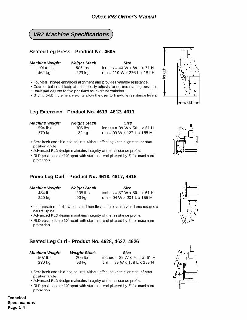
Seated Leg Press - Product No. 4605
Machine Weight Weight Stack Size1016 lbs. 505 lbs. inches = 43 W x 89 L x 71 H462 kg 229 kg cm = 110 W x 226 L x 181 H
• Four-bar linkage enhances alignment and provides variable resistance.• Counter-balanced footplate effortlessly adjusts for desired starting position.• Back pad adjusts to five positions for exercise variation.• Sliding 5-LB increment weights allow the user to fine-tune resistance levels.
Leg Extension - Product No. 4613, 4612, 4611
Machine Weight Weight Stack Size594 lbs. 305 lbs. inches = 39 W x 50 L x 61 H270 kg 139 kg cm = 99 W x 127 L x 155 H
• Seat back and tibia pad adjusts without affecting knee alignment or start position angle.
• Advanced RLD design maintains integrity of the resistance profile.• RLD positions are 10
oapart with start and end phased by 5
ofor maximum
protection.
Prone Leg Curl - Product No. 4618, 4617, 4616
Machine Weight Weight Stack Size484 lbs. 205 lbs. inches = 37 W x 80 L x 61 H220 kg 93 kg cm = 94 W x 204 L x 155 H
• Incorporation of elbow pads and handles is more sanitary and encourages a neutral spine.
• Advanced RLD design maintains integrity of the resistance profile.• RLD positions are 10
oapart with start and end phased by 5
ofor maximum
protection.
Seated Leg Curl - Product No. 4628, 4627, 4626
Machine Weight Weight Stack Size507 lbs. 205 lbs. inches = 39 W x 70 L x 61 H230 kg 93 kg cm = 99 W x 178 L x 155 H
• Seat back and tibia pad adjusts without affecting knee alignment of start position angle.
• Advanced RLD design maintains integrity of the resistance profile.• RLD positions are 10
oapart with start and end phased by 5
ofor maximum
protection.
leng
th
width
Technical SpecificationsPage 1-4
Cybex VR2 Owner’s Manual
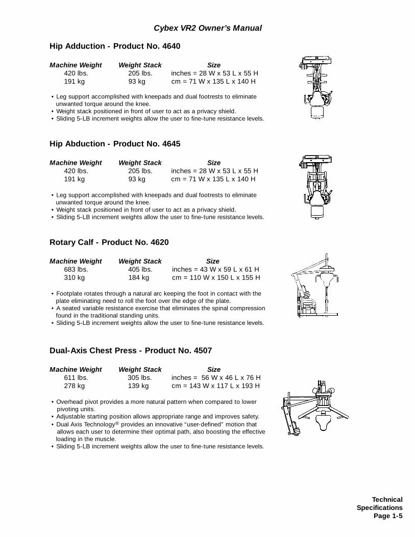
Hip Adduction - Product No. 4640
Machine Weight Weight Stack Size420 lbs. 205 lbs. inches = 28 W x 53 L x 55 H191 kg 93 kg cm = 71 W x 135 L x 140 H
• Leg support accomplished with kneepads and dual footrests to eliminate unwanted torque around the knee.
• Weight stack positioned in front of user to act as a privacy shield.• Sliding 5-LB increment weights allow the user to fine-tune resistance levels.
Hip Abduction - Product No. 4645
Machine Weight Weight Stack Size420 lbs. 205 lbs. inches = 28 W x 53 L x 55 H191 kg 93 kg cm = 71 W x 135 L x 140 H
• Leg support accomplished with kneepads and dual footrests to eliminate unwanted torque around the knee.
• Weight stack positioned in front of user to act as a privacy shield.• Sliding 5-LB increment weights allow the user to fine-tune resistance levels.
Rotary Calf - Product No. 4620
Machine Weight Weight Stack Size683 lbs. 405 lbs. inches = 43 W x 59 L x 61 H310 kg 184 kg cm = 110 W x 150 L x 155 H
• Footplate rotates through a natural arc keeping the foot in contact with the plate eliminating need to roll the foot over the edge of the plate.
• A seated variable resistance exercise that eliminates the spinal compression found in the traditional standing units.
• Sliding 5-LB increment weights allow the user to fine-tune resistance levels.
Dual-Axis Chest Press - Product No. 4507
Machine Weight Weight Stack Size611 lbs. 305 lbs. inches = 56 W x 46 L x 76 H278 kg 139 kg cm = 143 W x 117 L x 193 H
• Overhead pivot provides a more natural pattern when compared to lower pivoting units.
• Adjustable starting position allows appropriate range and improves safety.• Dual Axis Technology® provides an innovative “user-defined” motion that
allows each user to determine their optimal path, also boosting the effectiveloading in the muscle.
• Sliding 5-LB increment weights allow the user to fine-tune resistance levels.
TechnicalSpecifications
Page 1-5
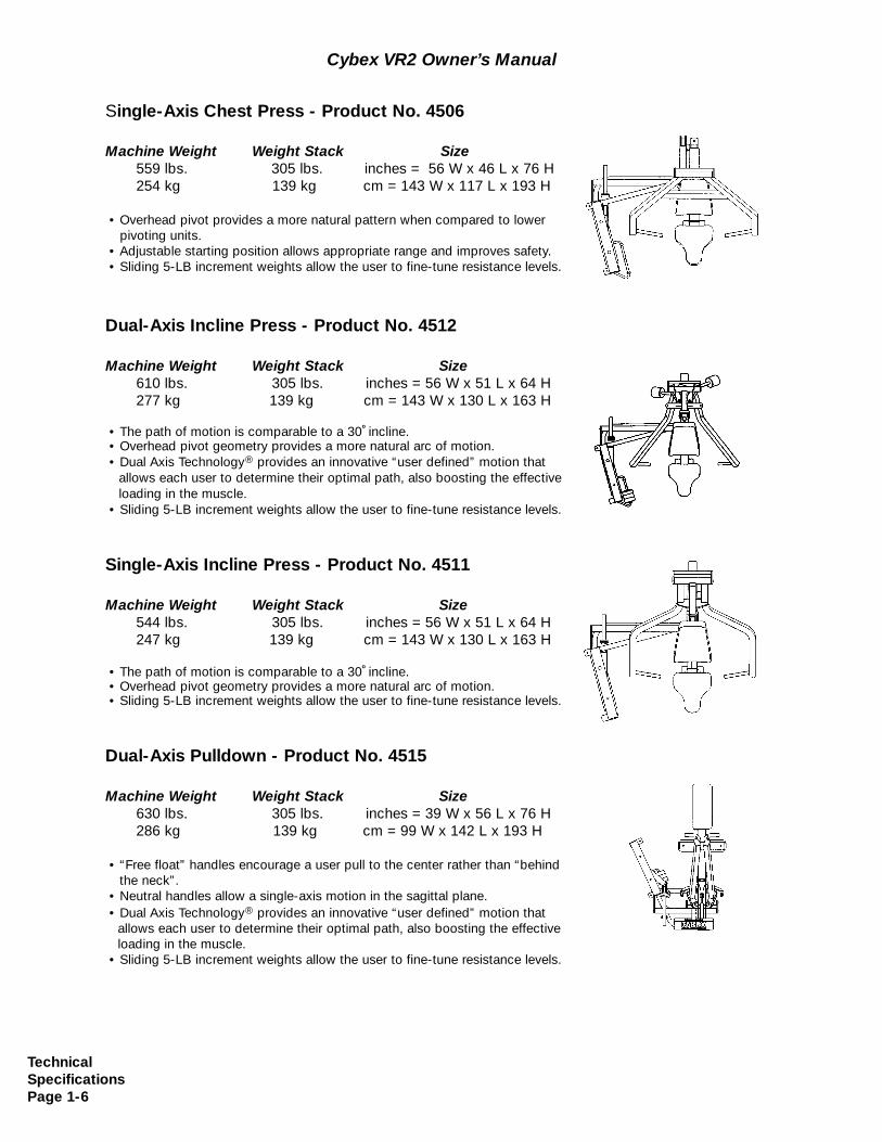
Single-Axis Chest Press - Product No. 4506
Machine Weight Weight Stack Size559 lbs. 305 lbs. inches = 56 W x 46 L x 76 H254 kg 139 kg cm = 143 W x 117 L x 193 H
• Overhead pivot provides a more natural pattern when compared to lower pivoting units.
• Adjustable starting position allows appropriate range and improves safety.• Sliding 5-LB increment weights allow the user to fine-tune resistance levels.
Dual-Axis Incline Press - Product No. 4512
Machine Weight Weight Stack Size610 lbs. 305 lbs. inches = 56 W x 51 L x 64 H277 kg 139 kg cm = 143 W x 130 L x 163 H
• The path of motion is comparable to a 30oincline.
• Overhead pivot geometry provides a more natural arc of motion.• Dual Axis Technology® provides an innovative “user defined” motion that
allows each user to determine their optimal path, also boosting the effective loading in the muscle.
• Sliding 5-LB increment weights allow the user to fine-tune resistance levels.
Single-Axis Incline Press - Product No. 4511
Machine Weight Weight Stack Size544 lbs. 305 lbs. inches = 56 W x 51 L x 64 H247 kg 139 kg cm = 143 W x 130 L x 163 H
• The path of motion is comparable to a 30oincline.
• Overhead pivot geometry provides a more natural arc of motion.• Sliding 5-LB increment weights allow the user to fine-tune resistance levels.
Dual-Axis Pulldown - Product No. 4515
Machine Weight Weight Stack Size630 lbs. 305 lbs. inches = 39 W x 56 L x 76 H286 kg 139 kg cm = 99 W x 142 L x 193 H
• “Free float” handles encourage a user pull to the center rather than “behind the neck”.
• Neutral handles allow a single-axis motion in the sagittal plane.• Dual Axis Technology® provides an innovative “user defined” motion that
allows each user to determine their optimal path, also boosting the effective loading in the muscle.
• Sliding 5-LB increment weights allow the user to fine-tune resistance levels.
Cybex VR2 Owner’s Manual
TechnicalSpecificationsPage 1-6
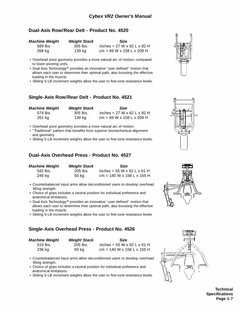
Dual-Axis Row/Rear Delt - Product No. 4520
Machine Weight Weight Stack Size589 lbs. 305 lbs. inches = 27 W x 62 L x 82 H268 kg 139 kg cm = 69 W x 158 L x 209 H
• Overhead pivot geometry provides a more natural arc of motion, compared to lower pivoting units.
• Dual Axis Technology® provides an innovative “user defined” motion that allows each user to determine their optimal path, also boosting the effective loading in the muscle.
• Sliding 5-LB increment weights allow the user to fine-tune resistance levels.
Single-Axis Row/Rear Delt - Product No. 4521
Machine Weight Weight Stack Size574 lbs. 305 lbs. inches = 27 W x 62 L x 82 H261 kg 139 kg cm = 69 W x 158 L x 209 H
• Overhead pivot geometry provides a more natural arc of motion.• “Traditional” pattern that benefits from superior biomechanical alignment
and geometry.• Sliding 5-LB increment weights allow the user to fine-tune resistance levels.
Dual-Axis Overhead Press - Product No. 4527
Machine Weight Weight Stack Size542 lbs. 205 lbs. inches = 55 W x 62 L x 61 H246 kg 93 kg cm = 140 W x 158 L x 155 H
• Counterbalanced input arms allow deconditioned users to develop overheadlifting strength.
• Choice of grips includes a neutral position for individual preference and anatomical limitations.
• Dual Axis Technology® provides an innovative “user defined” motion that allows each user to determine their optimal path, also boosting the effective loading in the muscle.
• Sliding 5-LB increment weights allow the user to fine-tune resistance levels.
Single-Axis Overhead Press - Product No. 4526
Machine Weight Weight Stack Size519 lbs. 205 lbs. inches = 55 W x 62 L x 61 H236 kg 93 kg cm = 140 W x 158 L x 155 H
• Counterbalanced input arms allow deconditioned users to develop overheadlifting strength.
• Choice of grips includes a neutral position for individual preference and anatomical limitations.
• Sliding 5-LB increment weights allow the user to fine-tune resistance levels.
Cybex VR2 Owner’s Manual
TechnicalSpecifications
Page 1-7
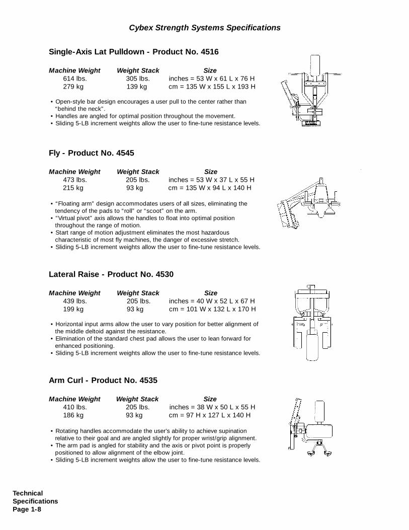
Single-Axis Lat Pulldown - Product No. 4516
Machine Weight Weight Stack Size614 lbs. 305 lbs. inches = 53 W x 61 L x 76 H279 kg 139 kg cm = 135 W x 155 L x 193 H
• Open-style bar design encourages a user pull to the center rather than “behind the neck”.
• Handles are angled for optimal position throughout the movement.• Sliding 5-LB increment weights allow the user to fine-tune resistance levels.
Fly - Product No. 4545
Machine Weight Weight Stack Size473 lbs. 205 lbs. inches = 53 W x 37 L x 55 H215 kg 93 kg cm = 135 W x 94 L x 140 H
• “Floating arm” design accommodates users of all sizes, eliminating the tendency of the pads to “roll” or “scoot” on the arm.
• “Virtual pivot” axis allows the handles to float into optimal position throughout the range of motion.
• Start range of motion adjustment eliminates the most hazardous characteristic of most fly machines, the danger of excessive stretch.
• Sliding 5-LB increment weights allow the user to fine-tune resistance levels.
Lateral Raise - Product No. 4530
Machine Weight Weight Stack Size439 lbs. 205 lbs. inches = 40 W x 52 L x 67 H199 kg 93 kg cm = 101 W x 132 L x 170 H
• Horizontal input arms allow the user to vary position for better alignment of the middle deltoid against the resistance.
• Elimination of the standard chest pad allows the user to lean forward for enhanced positioning.
• Sliding 5-LB increment weights allow the user to fine-tune resistance levels.
Arm Curl - Product No. 4535
Machine Weight Weight Stack Size410 lbs. 205 lbs. inches = 38 W x 50 L x 55 H186 kg 93 kg cm = 97 H x 127 L x 140 H
• Rotating handles accommodate the user’s ability to achieve supination relative to their goal and are angled slightly for proper wrist/grip alignment.
• The arm pad is angled for stability and the axis or pivot point is properly positioned to allow alignment of the elbow joint.
• Sliding 5-LB increment weights allow the user to fine-tune resistance levels.
Cybex Strength Systems Specifications
TechnicalSpecificationsPage 1-8
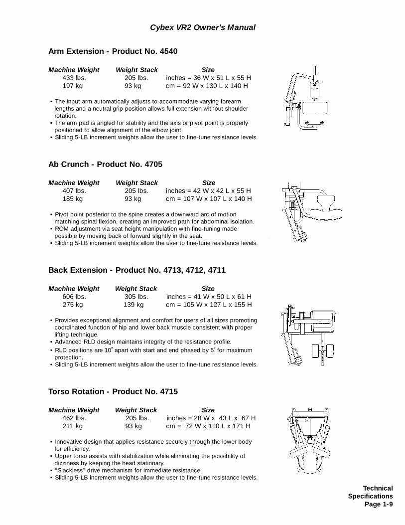
Arm Extension - Product No. 4540
Machine Weight Weight Stack Size433 lbs. 205 lbs. inches = 36 W x 51 L x 55 H197 kg 93 kg cm = 92 W x 130 L x 140 H
• The input arm automatically adjusts to accommodate varying forearm lengths and a neutral grip position allows full extension without shoulder rotation.
• The arm pad is angled for stability and the axis or pivot point is properly positioned to allow alignment of the elbow joint.
• Sliding 5-LB increment weights allow the user to fine-tune resistance levels.
Ab Crunch - Product No. 4705
Machine Weight Weight Stack Size407 lbs. 205 lbs. inches = 42 W x 42 L x 55 H185 kg 93 kg cm = 107 W x 107 L x 140 H
• Pivot point posterior to the spine creates a downward arc of motion matching spinal flexion, creating an improved path for abdominal isolation.
• ROM adjustment via seat height manipulation with fine-tuning made possible by moving back of forward slightly in the seat.
• Sliding 5-LB increment weights allow the user to fine-tune resistance levels.
Back Extension - Product No. 4713, 4712, 4711
Machine Weight Weight Stack Size606 lbs. 305 lbs. inches = 41 W x 50 L x 61 H275 kg 139 kg cm = 105 W x 127 L x 155 H
• Provides exceptional alignment and comfort for users of all sizes promoting coordinated function of hip and lower back muscle consistent with proper lifting technique.
• Advanced RLD design maintains integrity of the resistance profile.• RLD positions are 10
oapart with start and end phased by 5
ofor maximum
protection.• Sliding 5-LB increment weights allow the user to fine-tune resistance levels.
Torso Rotation - Product No. 4715
Machine Weight Weight Stack Size462 lbs. 205 lbs. inches = 28 W x 43 L x 67 H211 kg 93 kg cm = 72 W x 110 L x 171 H
• Innovative design that applies resistance securely through the lower body for efficiency.
• Upper torso assists with stabilization while eliminating the possibility of dizziness by keeping the head stationary.
• “Slackless” drive mechanism for immediate resistance.• Sliding 5-LB increment weights allow the user to fine-tune resistance levels.
Cybex VR2 Owner’s Manual
TechnicalSpecifications
Page 1-9

Cybex VR2 Owner’s Manual
TechnicalSpecificationsPage 1-10
This page intentionally left blank
GeneralExercise
GuidelinesPage 2-1
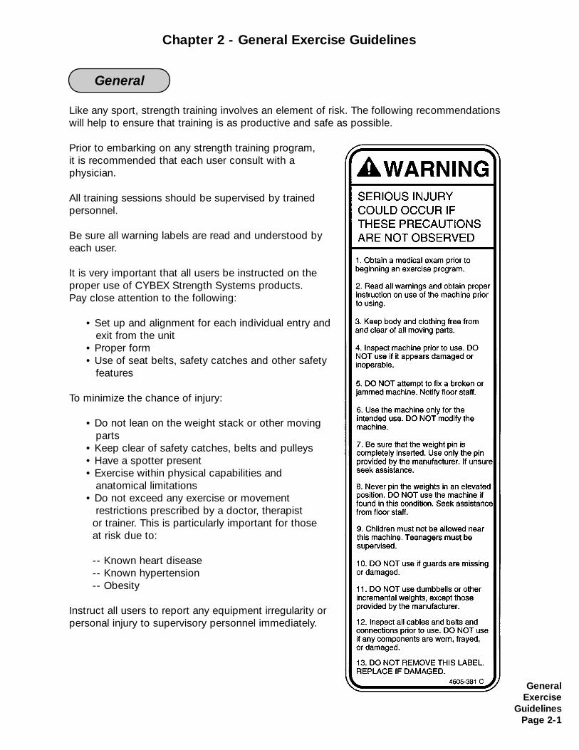
Like any sport, strength training involves an element of risk. The following recommendationswill help to ensure that training is as productive and safe as possible.
Prior to embarking on any strength training program, it is recommended that each user consult with a physician.
All training sessions should be supervised by trainedpersonnel.
Be sure all warning labels are read and understood byeach user.
It is very important that all users be instructed on theproper use of CYBEX Strength Systems products.Pay close attention to the following:
• Set up and alignment for each individual entry andexit from the unit
• Proper form• Use of seat belts, safety catches and other safety
features
To minimize the chance of injury:
• Do not lean on the weight stack or other moving parts
• Keep clear of safety catches, belts and pulleys• Have a spotter present• Exercise within physical capabilities and
anatomical limitations • Do not exceed any exercise or movement
restrictions prescribed by a doctor, therapistor trainer. This is particularly important for those at risk due to:
-- Known heart disease-- Known hypertension-- Obesity
Instruct all users to report any equipment irregularity orpersonal injury to supervisory personnel immediately.
General
Chapter 2 - General Exercise Guidelines
Abduction - movement away from the mid-line of the body.
Acceleration - the rate at which an object’s velocity changes with time; that is the change ofvelocity divided by the time interval.
Accuracy - freedom from error. Degree of conformity of a measure to a standard or a truevalue.
Action Line - the direction of pull created by the fibers or tendon of a muscle at the point of application.
Active Insufficiency - a two joint muscle loses the ability to cross-bridge (generate force) due to full shortening over its greatest anatomical length and tension created in an opposing muscle (antagonist).
Active Range of Motion - the degree of motion that occurs between two adjacent segmentsthrough voluntary contraction of the agonist (prime mover).
Active Stabilization - provided by an internal force. Static stabilization is provided through anisometric contraction where dynamic stabilization is a series of motions. Dynamic stabilizers maintain the relative positions of the segments, preventing undesirable or unnecessarymotions due to external forces as well as artifacts of internal forces. May also refer to theconcentric/eccentric contractions of a muscle acting in a force couple to produce motionwhile maintaining a relatively fixed axis of rotation.
Adipose Tissue - fat tissue.
Adduction - movement towards the mid-line of the body.
Agonist - (prime mover) a muscle that is mechanically optimal to produce a specific motion ata joint. There typically is more than one agonist for a peticular motion. A specific muscle canbe an agonist for more than one motion at a joint.
Aerobic - with or in the presence of oxygen oxygen.
Aerobic Endurance - the ability to persist in physical activities that rely heavily upon oxygenfor energy production.
Anabolic - pertaining to the synthesis of complex substances from simpler substances, espe-cially to the synthesis of body proteins from amino acids.
Anaerobic - without oxygen.
Cybex VR2 Owner’s Manual
Glossary
GeneralExerciseGuidelinesPage 2-2
Cybex VR2 Owner’s Manual
GeneralExercise
GuidelinesPage 2-3
Anaerobic Endurance - the ability to persist in physical activities of short duration thatrequire high rates of energy expenditure. These high rates of energy expenditure cannot bemet solely by aerobic metabolism.
Anthropometrics - measurements and relationships of length and girth of body parts.
Antagonist- the muscle in opposition to the agonist.
Anatomical Position - standing erect, with feet and palms facing forward.
Anatomical Pulley - a bone or skeletal prominence that alters the direction of the pull of amuscle to increase the muscle’s mechanical advantage.
Anatomy - geography, naming by orientation and/or apparent capability (non-functional).
Anchor Points - the points at which a load enters and exits the body and/or limb.
Anterior - anatomical term meaning towards the front. Same as ventral.
Assistant Mover - a muscle that is less effective at performing a specified motion, but does have a small degree of mechanical ability to help the prime mover. There are many borderline cases.
Atrophy - reduction in size of cells and tissues.
Axis of Rotation - imaginary line or point which an object rotates.
Bilateral - refers to both sides.
Biolocomotion - a perspective/description of the human body and its mechanics based upon locomotion. All animals with legs (regardless of numbers) move with the same mechanics. Gravity is the common denominator.
Biomechanics - the study of motion and the effect of forces on biological systems. In resistance training it is the analysis of the load placed on a joint by both the muscle and resistance. Anatomy, Kinesiology, and Physics = Engineering.
Body Composition - the component parts of the body - mainly fat and fat-free weight (leanbody mass).
Calorie - a unit of work or energy equal to the amount of heat required to raise the tempera-ture of 1 g of water to 1 degree C.
Cam - a mechanical device used to vary leverage. Based on the fact that a musclesmechanical advantage changes as it moves through a range of motion.
Cybex VR2 Owner’s Manual
GeneralExerciseGuidelinesPage 2-4
Carbohydrate - a chemical compound consisting of carbon, hydrogen and oxygen atoms in specified arrangements. Carbohydrates are the chief source of energy for all body functionsand anaerobic muscular exertion; they are major components of food such as bread, potatoes and rice.
Cardiovascular - pertaining to the heart and blood vessels.
Cartilage - there are several types. Hyaline cartilage is a relatively thin covering on the endsof many bones. It forms a smooth, resilient, low friction surface for the movement of one bone on another. Wedges of cartilage (fibrocartilage) called menisci, disks and labrums function toincrease stability, provide shock absorption, and to facilitate motion in some joints.
Center of Gravity - the center of a body’s mass. In the human body, it is the point which all parts are in balance with one another. It is dependent on current position in space, anatomicalstructure, gender, habitual standing posture and if external objects are being held.
Circumduction - a circular movement permitted at ball and socket, condylar and saddlejoints. Consists of flexion, abduction, extension and adduction in sequence.
Circuit Training - a type of conditioning program in which exercises are performed insequence, with little or no rest inbetween stations.
Closed Kinetic Chain Exercise - a series of rigid links interconnected by a series of pin-cen-tered joints. These are constructed so that motion at one joint will produce motion at all thejoints in the system. Closed-chain exercises produce greater mechanical efficiency at the riskof increased joint loading. Example, leg press, bench press.
Close-Packed Position - all synovial joints have a position where joint surfaces are maximal-ly congruent and the ligaments and capsule are maximally taut. This is a position of maximalstability and decreased mobility.
Collagen - a fibrous protein that serves as the major component of ligaments and tendons.
Compression - two forces acting along the same line towards each other that constitute acompressive load or compressive stress.
Concentric action - contraction of a muscle resulting in shortening of the muscle. Positivework is performed.
Connective Tissue - comprised of mostly the proteins collagen and elastin with water;includes tendons, ligaments, bursae, cartilage, disks, menisci, fascia and bone.
Cross-Bridge - the connection and intertwining of the actin and myosin filaments in amyofibril relative to a muscular contraction.
Curvilinear Motion - the frequently occurring combination of rotatory and translatorymotions.
GeneralExercise
GuidelinesPage 2-5
Cybex VR2 Owner’s Manual
Distraction - two forces acting along the same line and in opposite directions, they constitutea distractive, tensile load or tensile stress.
Diathrodial Joint - ball and socket joint.
Distal - furthest from the attached end of the limb; away from the body.
Dorsal - pertaining to the back; opposite of ventral, palmar or plantar.
Dorsiflexion - movement of the foot up in the sagittal plane; movement toward the leg.
Eccentric Action - muscle action in which tension is developed in the muscle while it islengthening. Negative work is performed.
Endurance - the ability to persist in performing some physical activity.
Energy - the capacity to perform work.
Energy (Kinetic) - energy associated with motion.
Energy (Potential) - energy by virtue of position.
Energy System - one of three metabolic systems involving a series of chemical reactionsresulting in the formation of waste products and the manufacture of ATP.
Eversion - movement of the sole of the foot outward; opposite of inversion.
Extension - movement about a joint in which bones on either side of the joint are broughtaway from each other, bringing two parts into or towards a straight line, increasing the angleof the joint. Returning to anatomical position from a position of flexion in the sagittal plane.
External Force - a push or pull on the body that arises from a source outside the body.
External Rotation - movement of the anterior surface of a segment away from the mid-line;also termed lateral rotation.
Fast Twitch Fibers - skeletal muscle fibers most active in short-duration, intensive exercise,e.g., in sprints and jumps.
Fatigue - the inability to maintain a given level of physical performance.
Flexibility - the range of movement of a specific joint or group of joints, influenced by theassociated bones and bony structures, muscles, tendons and ligaments.
Flexion - movement about a joint in which bones on either side of the joint are brought closertogether, decreasing the angle of the joint. Joint movement away from anatomical position,occurring within the sagittal plane.

Cybex VR2 Owner’s Manual
GeneralExerciseGuidelinesPage 2-6
Foot-Pound - the work required to move one pound of resistance one foot in distance.
Force - an interaction between two objects, in the form of a push or pull, that may or may notproduce motion, Force = mass x acceleration.
Force Angle - (FA) the angle between the action line and the lever, on the side of the jointaxis. It is not directly related to the joint angle and changes as the muscle’s relationship to thebone changes during motion
Force Couple - concentric/eccentric contractions of opposing muscles acting to producemotion while maintaining a relatively fixed axis of rotation. A prime example occurs in theshoulder, where the deltoid and rotator cuff muscles’ divergent pull create an almost perfectspinning of the humeral head around a fixed axis of rotation.
Frontal Plane - (coronal) imaginary line that divides the body into anterior and posteriorhalves; lies at a right angle to the sagittal plane.
Fulcrum - the support on which a lever rotates in moving or lifting.
Hyperextension - continuation of the movement of extension past the neutral position.
Hypertension - a chronic elevation of arterial blood pressure which is a primary risk factor forcoronary artery disease and stroke.
Hypertrophy - increased cell size leading to increased tissue size.
Impulse - the change in momentum. This becomes a concern in weight training, due to thepossible negative effects associated with it.
Inertia - the tendency of a body to remain at rest or continue in uniform motion unless actedon by an unbalanced force. Represents Newton’s first law, the law of inertia.
Inferior - a lower position upon or within the body.
Insertion - the more distal attachment site of a muscle. The movable part or attachment of amuscle as opposed to origin.
Intermittent Work - work sessions interrupted by rest sessions.
Internal Forces - act on the body and arise from sources within the human body.
Inversion - moving the sole of the foot inward. Opposite of eversion.
Isokinetic Contraction - a muscular contraction through a range of motion at a constant velocity. The rate of movement is maintained at a constant velocity through a specific range ofmotion even though maximal force is exerted.
GeneralExercise
GuidelinesPage 2-7
Cybex VR2 Owner’s Manual
Isometric (Static) Contraction - a muscular contraction in which tension is produced butthere is no change in the angle of the involved joint(s) involved.
Isotonic Contraction - a muscular contraction in which a constant resistance is movedthrough a range of motion of the involved joint(s). Movement in this type of contraction typi-cally involves both a concentric and an eccentric contraction.
Joint Play - “slack” in the connective tissues surrounding the joint that is required to allow normal joint motion.
Kilocalorie - a unit of work or energy equal to the amount of heat required to raise the temperature of 1 kg of water 1 degree C.
Kinematics - area of study that examines the spatial and temporal components of motion (position, velocity and acceleration).
Kinesiology - The scientific study of human movement.
Kinetic energy - energy associated with motion.
Kinetics - area of study that examines the forces that act on a system.
Kyphosis - neutral/normal sagittal curvature of the thoracic spine. Excessive kyphosis is oftenaccompanied by rounded shoulders.
Lactic Acid (Lactate) - the temporary end-product of anaerobic glucose metabolism (glycolysis).
Lean Body Mass - body weight minus body fat; composed of muscle, bone and other non-fat tissue.
Lever - a rigid bar that rotates around a fixed support (fulcrum) in response to an appliedforce.
Lever Systems - a force system existing whenever two or more parallel forces, whoseactions lines will never converge, act on the same object but at some distance from eachother. The three classifications are first, second and third class levers.
Ligament - a band of fibrous connective tissue that binds bone to bone; functions to maintainintegrity of a joint.
Lordosis - neutral/normal forward curvature of the lumbar and cervical spine.
Luxation - complete joint dislocation.
Mass - the amount of matter an object contains, or the number of atoms. Unlike weight, an objects mass is constant, despite the value of gravitational acceleration. Mass is a determinerof an object’s inertia.
GeneralExerciseGuidelinesPage 2-8
Cybex VR2 Owner’s Manual
Mechanical Efficiency - greater mechanical efficiency, relative to resistance training, meansless muscular force is required to move a load and therefore greater stress is transferredthrough the skeletal system. The value of the system utilized becomes dependent upon thegoal.
Medial Rotation - movement around an axis and toward the mid-line of the body. Alsotermed internal rotation.
Medial - aspect nearest the mid-line of the body; pertaining to the center. Opposite of lateral.
Metabolism - the sum total of the energy-producing and -absorbing processes in the body.The energy used by the body.
Moment Arm - (MA) the shortest distance between the action line and the joint axis.
Momentum - the product of the mass of a body and its velocity. It will remain constant (it is“conserved”) unless the object is acted upon by another force.
Muscle Contraction - shortening of a muscle and/or development of tension in a muscle.
Muscular Endurance - the ability of a muscle or muscle group to perform repeated contractions against a load for an extended period of time.
Neutral - a point between the two extremes of a joint’s range of motion.
Obesity - the clinical classification of a percent body fat greater than 25% (males) or 30%(females).
Open Kinematic Chain - the ends of the limbs or parts are free to move without causingmotion at another joint. Open chain motions are not predictable because the joints may function either independently or in unison. Less mechanically efficient, therefore more stress is placed upon muscular tissue. Examples, dumbbell presses and curls.
Origin - attachment of a muscle that remains relatively fixed during muscular contraction.
Overload - stressing the body or parts against resistance greater than that which is normallyencountered. The resistance (load) can be maximal or near-maximal.
Passive Insufficiency - the point at which a two-joint muscle loses the ability to cross-bridge(generate force) due to full lengthening over its greatest anatomical length due to force created in an opposing muscle.
Passive Stabilization - a type of stabilization that is due to non-contractile components. Thiscan be accomplished internally by connective tissue (in situations of non-muscular support);or through external structures such as a bench or brace.
Plane of Motion - a two-dimensional flat surface running through an object. Motion occurs inthe plane or parallel to the plane.
GeneralExercise
GuidelinesPage 2-9
Cybex VR2 Owner’s Manual
Plantar - anatomical term referring to the sole or bottom.
Plantarflexion - movement of the foot down in the sagittal plane; movement away from theleg.
Posterior - anatomical term meaning toward the back. Opposite of anterior.
Potential Energy - energy by virtue of position.
Power - the product of work divided by time. It is the time required to move a distance thatwas produced by the force.
Prime Mover - (agonist) a muscle that is mechanically optimal to produce a specific motionat a joint. There can be more than one prime mover for a particular motion, and a specificmuscle can be a prime mover for more than one motion at a joint.
Progressive Resistance - overloading a muscle or muscle group consistently throughout the duration of a weight-resistance program.
Pronation - a triplanar motion at the subtalar joint consisting of abduction, depression andeversion, resulting in lowering of the longitudinal arch of the foot. Position of the forearm withthe palm facing down.
Protein - an essential nutrient made up of amino acids. The building block for tissues.
Proximal - towards the attached end of the limb or origin.
Range of Motion (ROM) - the amount of motion available to a joint (measured in degrees)within the anatomical limits of the joint structure. Limits to range of motion also include physiological, biomechanical, and neural. ROM can be classified as Passive (movement produced via a force outside the limb), Active (movement produced by muscles within thelimb) or Resisted (movement challenged under additional load).
Reciprocal Inhibition - contraction of agonist causes relaxation of antagonist.
Repetition Maximum (RM) - the maximum load that a muscle or muscle group can lift for given number of repetitions before fatiguing. Example, an eight-RM load is the maximum loadthat can be lifted eight times.
Rotary Motion - (radial or angular) the movement of an object around a fixed axis in a curvedpath.
S.A.I.D. Principle - Specific Adaptation to Imposed Demand. A muscle will gain strength inthe specific ranges of motion and speeds in which it is trained.
Sagittal Plane - Imaginary line that divides the body, or any of its parts, into right and left sections.
GeneralExerciseGuidelinesPage 2-10
Cybex VR2 Owner’s Manual
Scoliosis - a lateral curvature of the vertebral column, usually in the thoracic area.
Secondary Joint - hinge joints that have a singular function (elbow/knee). Muscles are situated on either side of these joints in virtual, if not real, pairings.
Set - in an interval training program, a group of work and relief intervals. In weight lifting, the number of repetitions performed consecutively without resting.
Shear - two parallel forces applied in opposite directions that are not in line with each otherconstitute a shearing load or stress within the object to which they are applied. Normal jointmotion is always associated with some degree of shearing stress due to normal muscularaction against resistance (weight of the limb, etc).
Shunt Muscle - directs the greater part of its contractile force along the bone it is moving (creating greater force towards compression/stabilization). Example, the brachioradialis muscle of the forearm is a shunt during an arm curl.
Skeletal Muscle - muscle controlling skeletal movement that is normally under voluntary control.
Sliding Filament Theory - a muscle shortens or lengthens due to the thick and thin myofibrils sliding past one another without the filaments changing length.
Slow-twitch Fibers - skeletal muscle fibers characterized by relatively slow contractilespeeds and great capacity for the aerobic production of adenosine triphosphate (ATP).
Sprain - the permanent deformation of the structure due to excessive or prolongedstress/strain.
Spurt Muscle - directs the greater part of its force across the bone it is moving rather thanalong it (creating greater effort towards motion). Example, the biceps is a spurt during an armcurl.
Stabilizer - a muscle that steadies or supports an adjacent joint in order for another activemuscle to have a firm base upon which to pull. A muscle may be a stabilizer for one motion,and a prime mover (agonist) for another motion.
Static Contraction - a muscular contraction that does not involve changes in the angle of thejoint(s) involved.
Steady State - that state of physiological stability wherein the energy demands of the bodycan be met relatively easily for a prolonged period of time.
Strain - the deformation of the structure as the result of stress.
Strength - the ability to exert muscular force briefly.
Stress - the force created within a structure when placed under load.
GeneralExercise
GuidelinesPage 2-11
Cybex VR2 Owner’s Manual
Subluxation - a partial dislocation of a joint; usually reduces itself.
Submaximal Exercise - exercise at less than maximal intensity, may also refer to exercise ofless than maximal duration.
Superior - a higher position upon or within the body.
Synergist - occurs during the action of two muscles, both of which have a common jointaction and each of which has a second action that is antagonistic or opposing to the other.True synergy is simply the stabilization of one muscle to prevent any action in one of the jointstraversed by a multi-joint muscle.
Synovial Fluid - a transparent, viscous lubricating fluid found in joint cavities, bursae and ten-don sheaths.
Tendons - cords of dense fibrous tissue that connect muscle to bone.
Tertiary Joint - a complex joint structure (wrist/ankle-subtalor), designed for finely controlledmovements.
Torque - the ability of a force to produce movement around an axis.
Translatory Motion - (linear) the movement of an object in a straight line.
Unilateral - refers to only one side.
Vector - typically represented by a drawn arrow, representing a force’s point of application,action line or direction indicating pull or magnitude of force being exerted.
Vector Shift - a manipulation of the force or loadline through the chain by altering the positionof the anchors relative to the joints or vice versa.
Velocity - the rate at which an objects position changes with time; that is the total change in position divided by the total change in time: V-d/t.
Weight - a unit of heaviness which is the product of the mass of an object and the gravita-tional force exerted on it by the earth. W=mg, where g = gravitational acceleration.
Work - W = Fd. The amount of work performed is equivalent to the force applied to an object times the distance the object is moved.
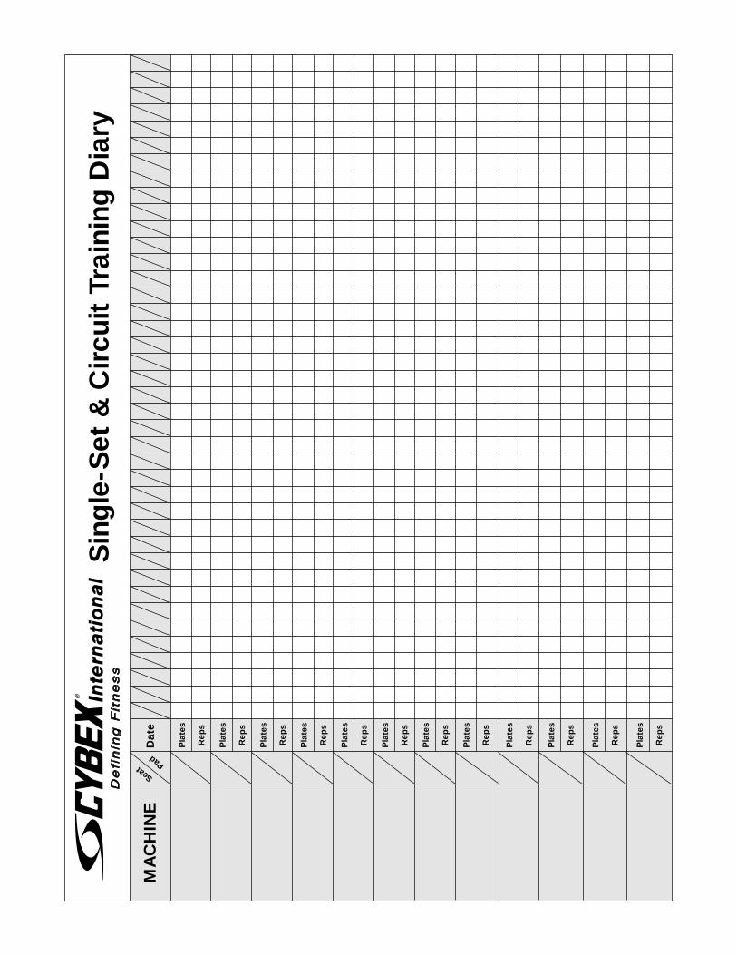
Sin
gle
-Set
& C
ircu
it T
rain
ing
Dia
ry
MA
CH
INE
Dat
e
Pla
tes
Rep
s
Pla
tes
Rep
s
Pla
tes
Rep
s
Pla
tes
Rep
s
Pla
tes
Rep
s
Pla
tes
Rep
s
Pla
tes
Rep
s
Pla
tes
Rep
s
Pla
tes
Rep
s
Pla
tes
Rep
s
Pla
tes
Rep
s
Pla
tes
Rep
s
Seat Pad
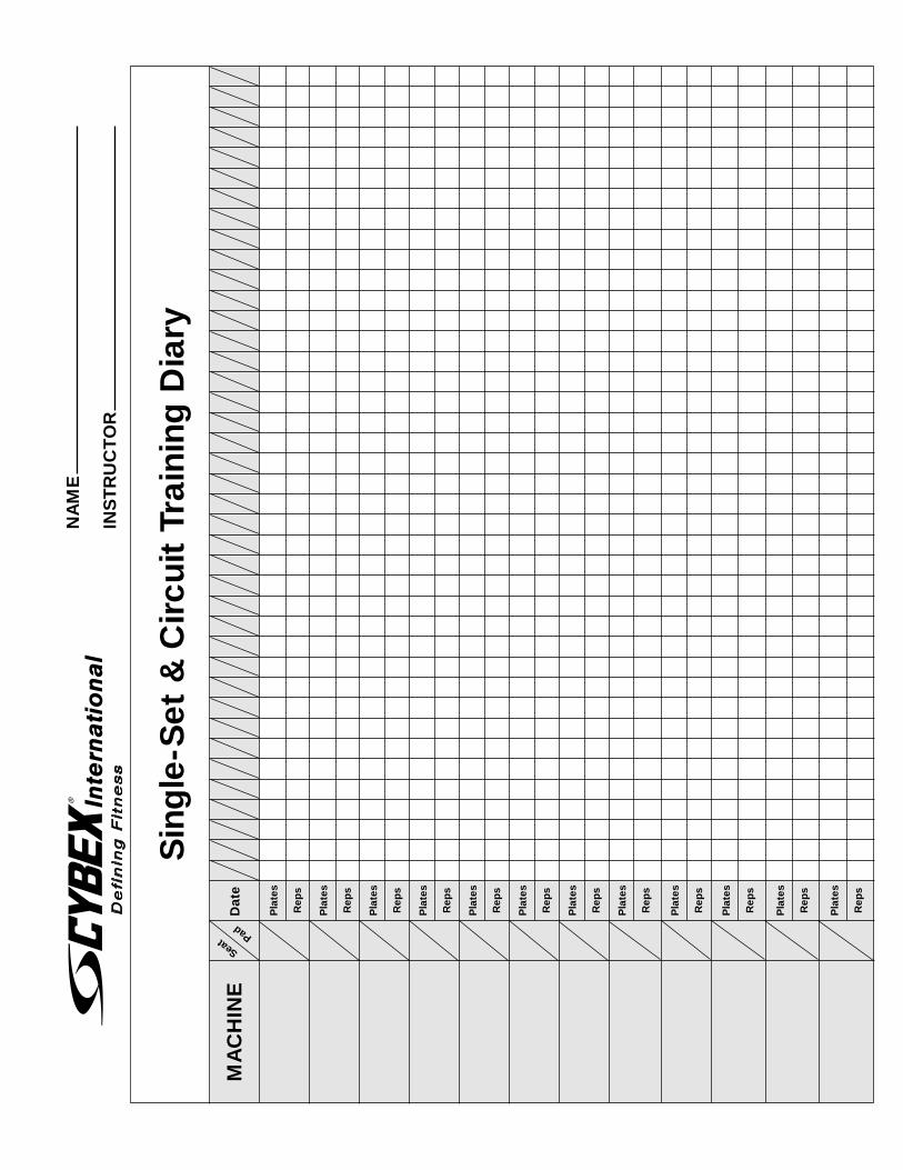
Sin
gle
-Set
& C
ircu
it T
rain
ing
Dia
ry
MA
CH
INE
Dat
e
Pla
tes
Rep
s
Pla
tes
Rep
s
Pla
tes
Rep
s
Pla
tes
Rep
s
Pla
tes
Rep
s
Pla
tes
Rep
s
Pla
tes
Rep
s
Pla
tes
Rep
s
Pla
tes
Rep
s
Pla
tes
Rep
s
Pla
tes
Rep
s
Pla
tes
Rep
s
Seat Pad
NA
ME
INS
TR
UC
TO
R
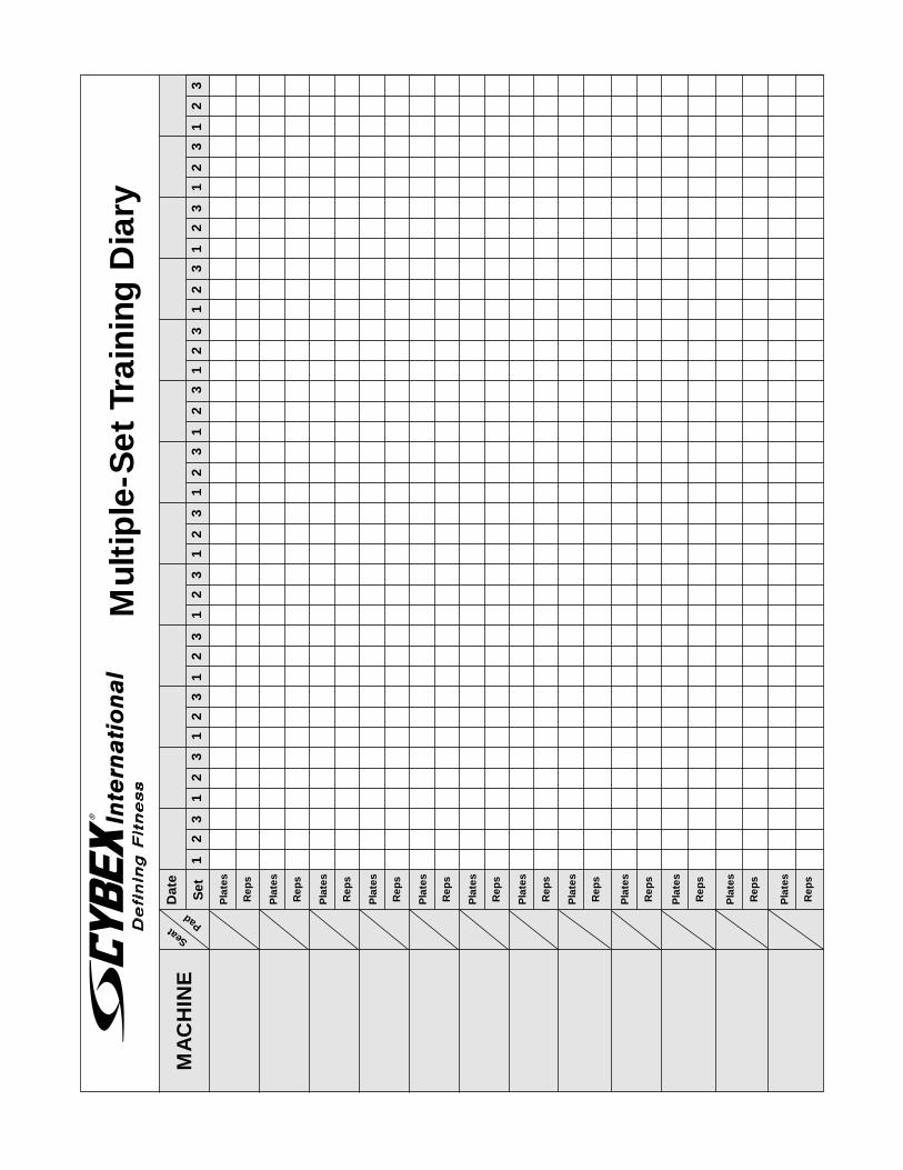
Mul
tip
le-S
et T
rain
ing
Dia
ry
MA
CH
INE
Dat
e
Set
Pla
tes
Rep
s
Pla
tes
Rep
s
Pla
tes
Rep
s
Pla
tes
Rep
s
Pla
tes
Rep
s
Pla
tes
Rep
s
Pla
tes
Rep
s
Pla
tes
Rep
s
Pla
tes
Rep
s
Pla
tes
Rep
s
Pla
tes
Rep
s
Pla
tes
Rep
s
Seat Pad
1
2
3
12
3 1
2
3
1
2
3
1
2
3
1
2
3
1
2
3
1
2
3
1
2
3
1
2
3
1
2
3
1
2
3
1
2
3
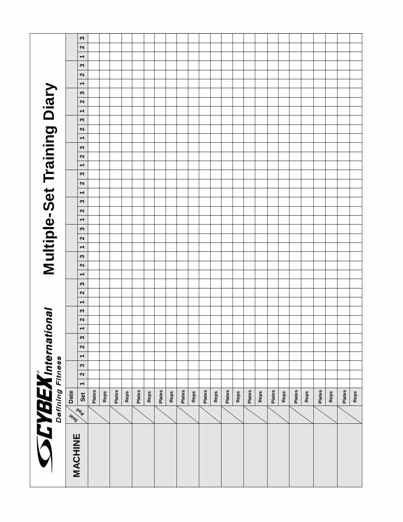
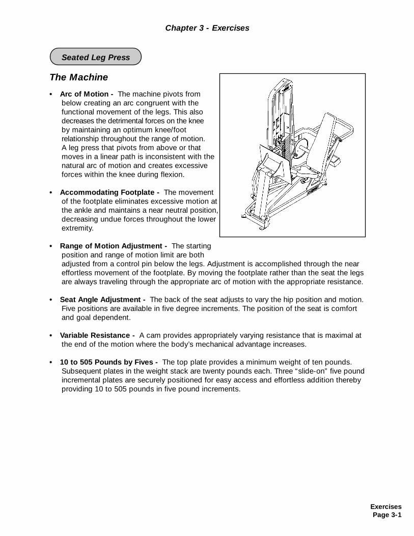
The Machine
• Arc of Motion - The machine pivots from below creating an arc congruent with the functional movement of the legs. This also decreases the detrimental forces on the knee by maintaining an optimum knee/footrelationship throughout the range of motion.A leg press that pivots from above or that moves in a linear path is inconsistent with the natural arc of motion and creates excessive forces within the knee during flexion.
• Accommodating Footplate - The movement of the footplate eliminates excessive motion at the ankle and maintains a near neutral position, decreasing undue forces throughout the lower extremity.
• Range of Motion Adjustment - The starting position and range of motion limit are both adjusted from a control pin below the legs. Adjustment is accomplished through the neareffortless movement of the footplate. By moving the footplate rather than the seat the legs are always traveling through the appropriate arc of motion with the appropriate resistance.
• Seat Angle Adjustment - The back of the seat adjusts to vary the hip position and motion.Five positions are available in five degree increments. The position of the seat is comfort and goal dependent.
• Variable Resistance - A cam provides appropriately varying resistance that is maximal atthe end of the motion where the body’s mechanical advantage increases.
• 10 to 505 Pounds by Fives - The top plate provides a minimum weight of ten pounds. Subsequent plates in the weight stack are twenty pounds each. Three “slide-on” five pound incremental plates are securely positioned for easy access and effortless addition thereby providing 10 to 505 pounds in five pound increments.
Chapter 3 - Exercises
ExercisesPage 3-1
Seated Leg Press
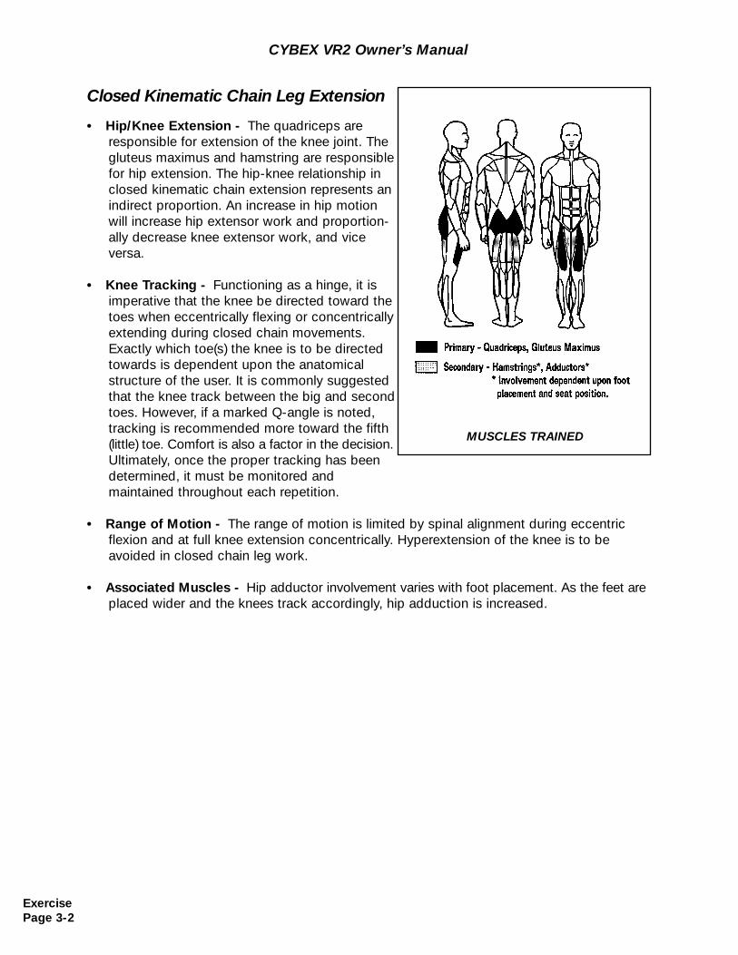
Closed Kinematic Chain Leg Extension
• Hip/Knee Extension - The quadriceps areresponsible for extension of the knee joint. The gluteus maximus and hamstring are responsible for hip extension. The hip-knee relationship in closed kinematic chain extension represents an indirect proportion. An increase in hip motion will increase hip extensor work and proportion-ally decrease knee extensor work, and vice versa.
• Knee Tracking - Functioning as a hinge, it is imperative that the knee be directed toward the toes when eccentrically flexing or concentrically extending during closed chain movements. Exactly which toe(s) the knee is to be directed towards is dependent upon the anatomical structure of the user. It is commonly suggested that the knee track between the big and second toes. However, if a marked Q-angle is noted, tracking is recommended more toward the fifth (little) toe. Comfort is also a factor in the decision. Ultimately, once the proper tracking has been determined, it must be monitored and maintained throughout each repetition.
• Range of Motion - The range of motion is limited by spinal alignment during eccentric flexion and at full knee extension concentrically. Hyperextension of the knee is to be avoided in closed chain leg work.
• Associated Muscles - Hip adductor involvement varies with foot placement. As the feet are placed wider and the knees track accordingly, hip adduction is increased.
MUSCLES TRAINED
CYBEX VR2 Owner’s Manual
ExercisePage 3-2
CYBEX VR2 Owner’s Manual
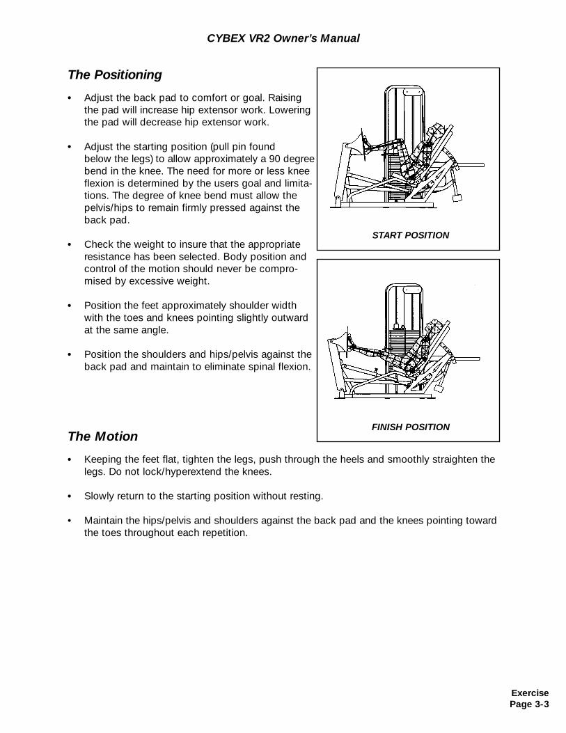
The Positioning
• Adjust the back pad to comfort or goal. Raising the pad will increase hip extensor work. Lowering the pad will decrease hip extensor work.
• Adjust the starting position (pull pin found below the legs) to allow approximately a 90 degreebend in the knee. The need for more or less knee flexion is determined by the users goal and limita-tions. The degree of knee bend must allow the pelvis/hips to remain firmly pressed against the back pad.
• Check the weight to insure that the appropriate resistance has been selected. Body position and control of the motion should never be compro-mised by excessive weight.
• Position the feet approximately shoulder width with the toes and knees pointing slightly outward at the same angle.
• Position the shoulders and hips/pelvis against the back pad and maintain to eliminate spinal flexion.
The Motion
• Keeping the feet flat, tighten the legs, push through the heels and smoothly straighten the legs. Do not lock/hyperextend the knees.
• Slowly return to the starting position without resting.
• Maintain the hips/pelvis and shoulders against the back pad and the knees pointing toward the toes throughout each repetition.
START POSITION
FINISH POSITION
ExercisePage 3-3

CYBEX VR2 Owner’s Manual
(This page intentionally left blank)
ExercisePage 3-4
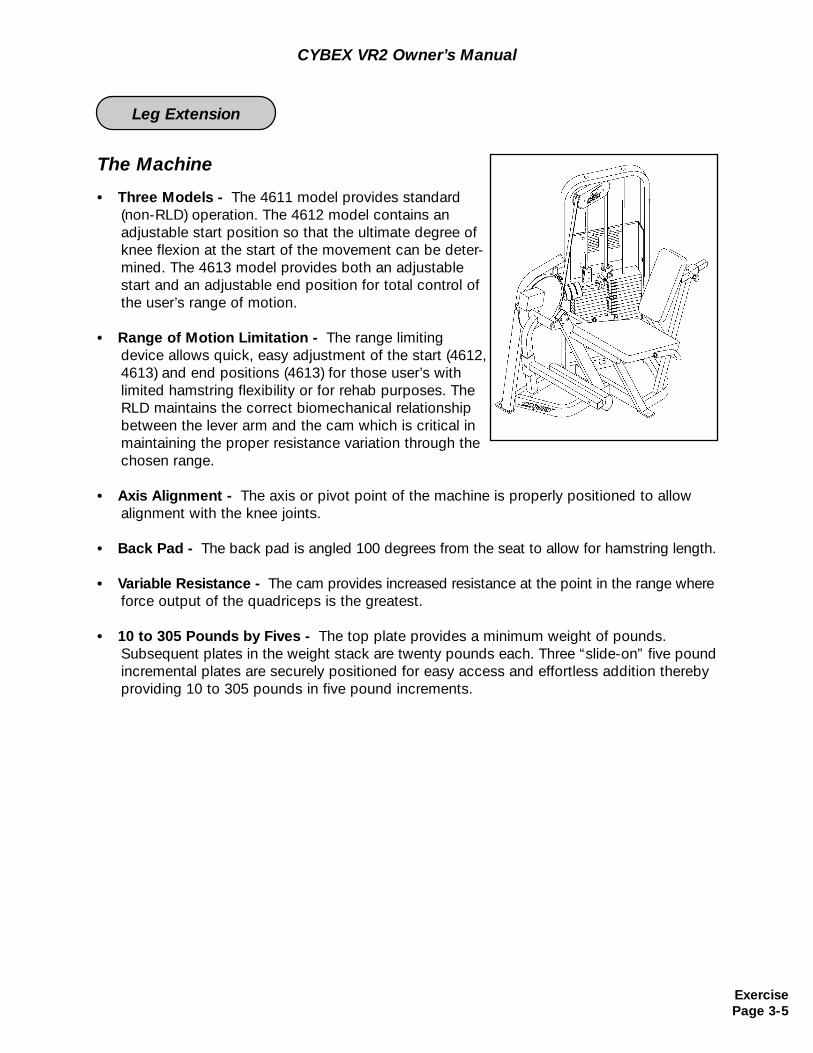
The Machine
• Three Models - The 4611 model provides standard (non-RLD) operation. The 4612 model contains an adjustable start position so that the ultimate degree of knee flexion at the start of the movement can be deter-mined. The 4613 model provides both an adjustable start and an adjustable end position for total control of the user’s range of motion.
• Range of Motion Limitation - The range limiting device allows quick, easy adjustment of the start (4612, 4613) and end positions (4613) for those user’s with limited hamstring flexibility or for rehab purposes. The RLD maintains the correct biomechanical relationship between the lever arm and the cam which is critical in maintaining the proper resistance variation through the chosen range.
• Axis Alignment - The axis or pivot point of the machine is properly positioned to allow alignment with the knee joints.
• Back Pad - The back pad is angled 100 degrees from the seat to allow for hamstring length.
• Variable Resistance - The cam provides increased resistance at the point in the range whereforce output of the quadriceps is the greatest.
• 10 to 305 Pounds by Fives - The top plate provides a minimum weight of pounds. Subsequent plates in the weight stack are twenty pounds each. Three “slide-on” five pound incremental plates are securely positioned for easy access and effortless addition thereby providing 10 to 305 pounds in five pound increments.
CYBEX VR2 Owner’s Manual
ExercisePage 3-5
Leg Extension
CYBEX VR2 Owner’s Manual
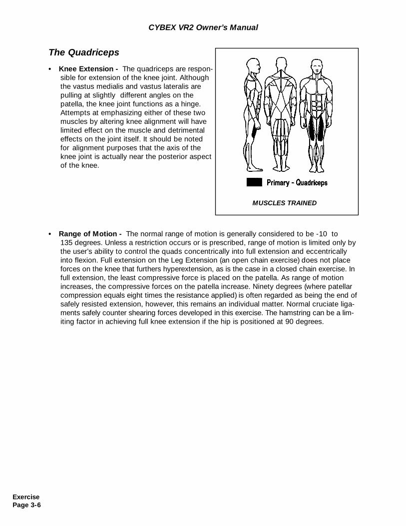
The Quadriceps
• Knee Extension - The quadriceps are respon-sible for extension of the knee joint. Although the vastus medialis and vastus lateralis are pulling at slightly different angles on the patella, the knee joint functions as a hinge. Attempts at emphasizing either of these two muscles by altering knee alignment will havelimited effect on the muscle and detrimental effects on the joint itself. It should be noted for alignment purposes that the axis of the knee joint is actually near the posterior aspect of the knee.
MUSCLES TRAINED
• Range of Motion - The normal range of motion is generally considered to be -10 to135 degrees. Unless a restriction occurs or is prescribed, range of motion is limited only by the user’s ability to control the quads concentrically into full extension and eccentrically into flexion. Full extension on the Leg Extension (an open chain exercise) does not place forces on the knee that furthers hyperextension, as is the case in a closed chain exercise. In full extension, the least compressive force is placed on the patella. As range of motion increases, the compressive forces on the patella increase. Ninety degrees (where patellar compression equals eight times the resistance applied) is often regarded as being the end of safely resisted extension, however, this remains an individual matter. Normal cruciate liga-ments safely counter shearing forces developed in this exercise. The hamstring can be a lim-iting factor in achieving full knee extension if the hip is positioned at 90 degrees.
ExercisePage 3-6
CYBEX VR2 Owner’s Manual
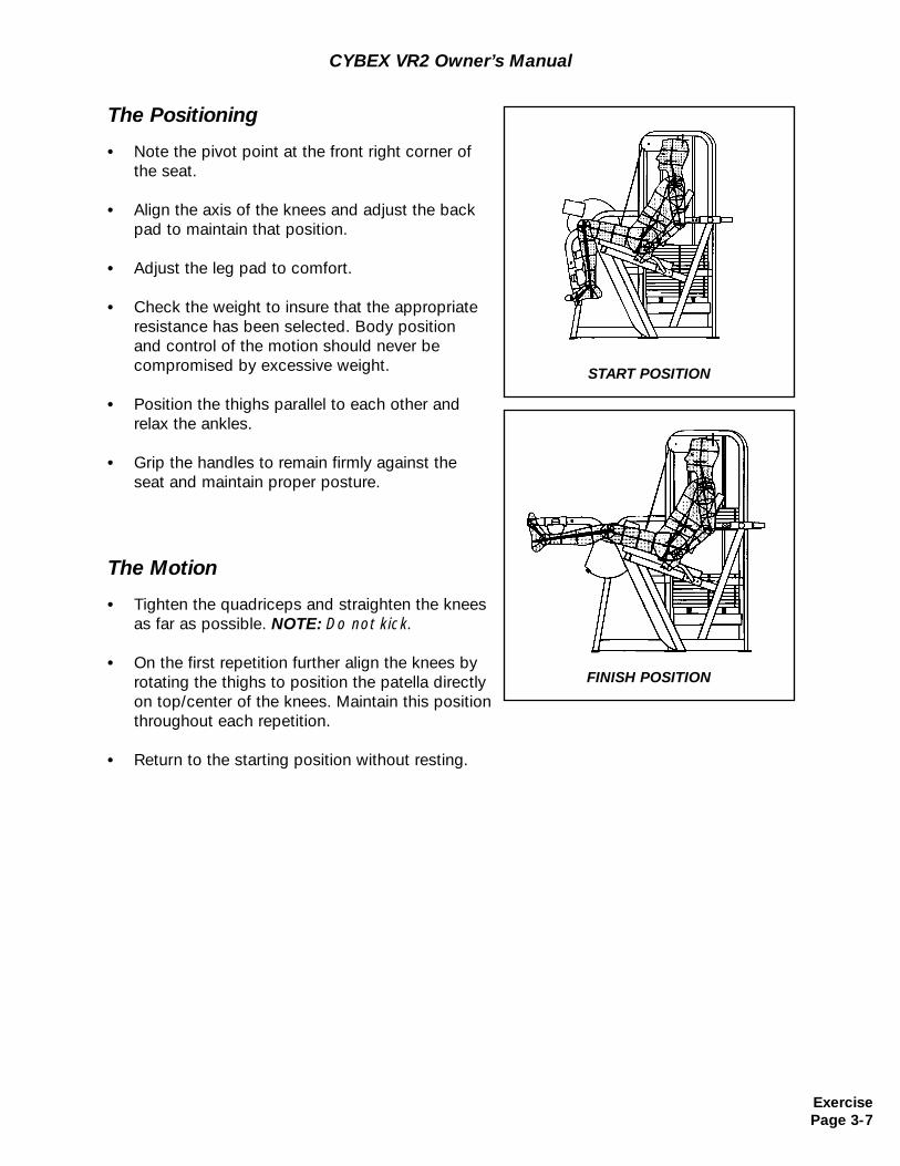
The Positioning
• Note the pivot point at the front right corner ofthe seat.
• Align the axis of the knees and adjust the back pad to maintain that position.
• Adjust the leg pad to comfort.
• Check the weight to insure that the appropriate resistance has been selected. Body position and control of the motion should never be compromised by excessive weight.
• Position the thighs parallel to each other and relax the ankles.
• Grip the handles to remain firmly against the seat and maintain proper posture.
The Motion
• Tighten the quadriceps and straighten the knees as far as possible. NOTE: Do not kick.
• On the first repetition further align the knees by rotating the thighs to position the patella directly on top/center of the knees. Maintain this positionthroughout each repetition.
• Return to the starting position without resting.
START POSITION
FINISH POSITION
ExercisePage 3-7
CYBEX VR2 Owner’s Manual
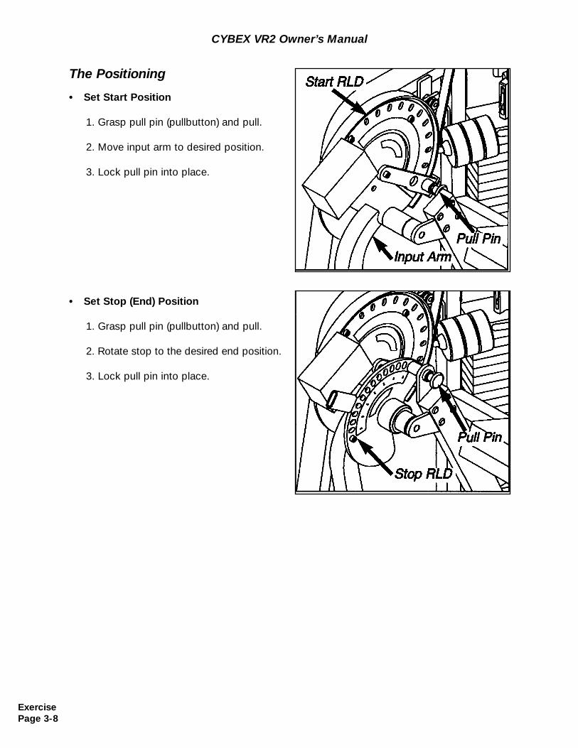
The Positioning
• Set Start Position
1. Grasp pull pin (pullbutton) and pull.
2. Move input arm to desired position.
3. Lock pull pin into place.
• Set Stop (End) Position
1. Grasp pull pin (pullbutton) and pull.
2. Rotate stop to the desired end position.
3. Lock pull pin into place.
ExercisePage 3-8
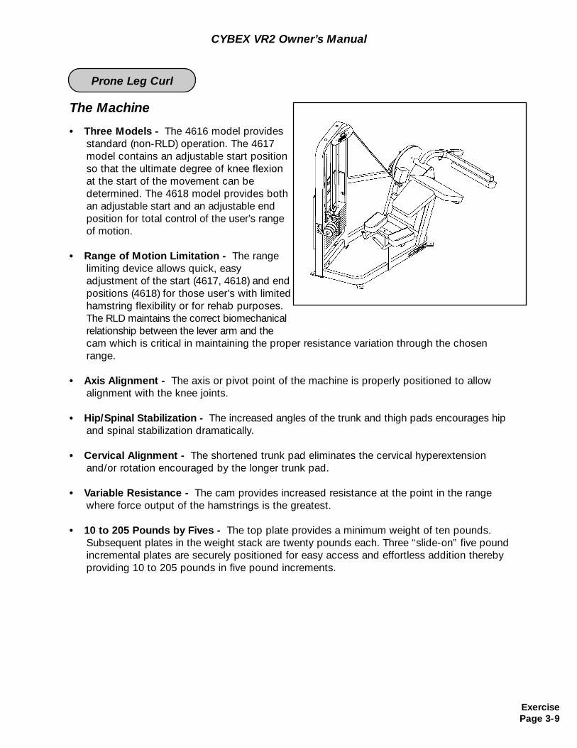
The Machine
• Three Models - The 4616 model provides standard (non-RLD) operation. The 4617 model contains an adjustable start position so that the ultimate degree of knee flexion at the start of the movement can be determined. The 4618 model provides both an adjustable start and an adjustable end position for total control of the user’s range of motion.
• Range of Motion Limitation - The range limiting device allows quick, easy adjustment of the start (4617, 4618) and endpositions (4618) for those user’s with limited hamstring flexibility or for rehab purposes. The RLD maintains the correct biomechanical relationship between the lever arm and the cam which is critical in maintaining the proper resistance variation through the chosenrange.
• Axis Alignment - The axis or pivot point of the machine is properly positioned to allow alignment with the knee joints.
• Hip/Spinal Stabilization - The increased angles of the trunk and thigh pads encourages hip and spinal stabilization dramatically.
• Cervical Alignment - The shortened trunk pad eliminates the cervical hyperextension and/or rotation encouraged by the longer trunk pad.
• Variable Resistance - The cam provides increased resistance at the point in the range where force output of the hamstrings is the greatest.
• 10 to 205 Pounds by Fives - The top plate provides a minimum weight of ten pounds. Subsequent plates in the weight stack are twenty pounds each. Three “slide-on” five poundincremental plates are securely positioned for easy access and effortless addition thereby providing 10 to 205 pounds in five pound increments.
CYBEX VR2 Owner’s Manual
ExercisePage 3-9
Prone Leg Curl
CYBEX VR2 Owner’s Manual
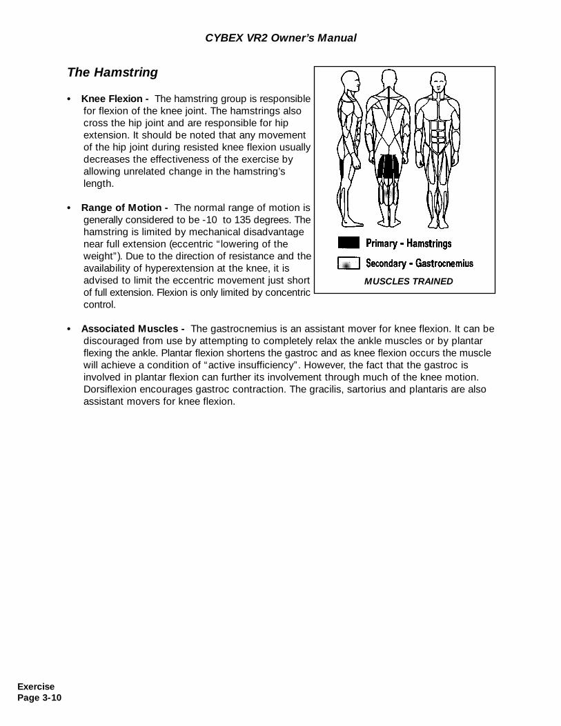
The Hamstring
• Knee Flexion - The hamstring group is responsible for flexion of the knee joint. The hamstrings also cross the hip joint and are responsible for hip extension. It should be noted that any movement of the hip joint during resisted knee flexion usually decreases the effectiveness of the exercise by allowing unrelated change in the hamstring’slength.
• Range of Motion - The normal range of motion is generally considered to be -10 to 135 degrees. Thehamstring is limited by mechanical disadvantagenear full extension (eccentric “lowering of the weight”). Due to the direction of resistance and the availability of hyperextension at the knee, it is advised to limit the eccentric movement just short of full extension. Flexion is only limited by concentric control.
• Associated Muscles - The gastrocnemius is an assistant mover for knee flexion. It can be discouraged from use by attempting to completely relax the ankle muscles or by plantar flexing the ankle. Plantar flexion shortens the gastroc and as knee flexion occurs the muscle will achieve a condition of “active insufficiency”. However, the fact that the gastroc is involved in plantar flexion can further its involvement through much of the knee motion. Dorsiflexion encourages gastroc contraction. The gracilis, sartorius and plantaris are also assistant movers for knee flexion.
MUSCLES TRAINED
ExercisePage 3-10
CYBEX VR2 Owner’s Manual
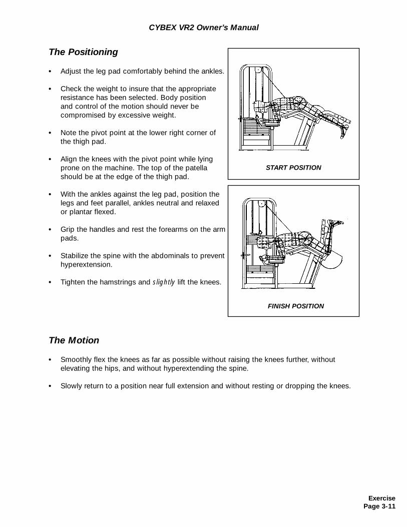
The Motion
• Smoothly flex the knees as far as possible without raising the knees further, without elevating the hips, and without hyperextending the spine.
• Slowly return to a position near full extension and without resting or dropping the knees.
The Positioning
• Adjust the leg pad comfortably behind the ankles.
• Check the weight to insure that the appropriate resistance has been selected. Body position and control of the motion should never be compromised by excessive weight.
• Note the pivot point at the lower right corner of the thigh pad.
• Align the knees with the pivot point while lying prone on the machine. The top of the patella should be at the edge of the thigh pad.
• With the ankles against the leg pad, position the legs and feet parallel, ankles neutral and relaxed or plantar flexed.
• Grip the handles and rest the forearms on the arm pads.
• Stabilize the spine with the abdominals to prevent hyperextension.
• Tighten the hamstrings and slightly lift the knees.
START POSITION
FINISH POSITION
ExercisePage 3-11
CYBEX VR2 Owner’s Manual
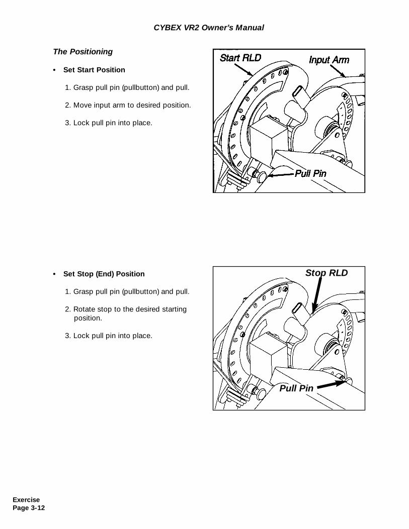
The Positioning
• Set Start Position
1. Grasp pull pin (pullbutton) and pull.
2. Move input arm to desired position.
3. Lock pull pin into place.
• Set Stop (End) Position
1. Grasp pull pin (pullbutton) and pull.
2. Rotate stop to the desired starting position.
3. Lock pull pin into place.
ExercisePage 3-12
Stop RLD
Pull Pin
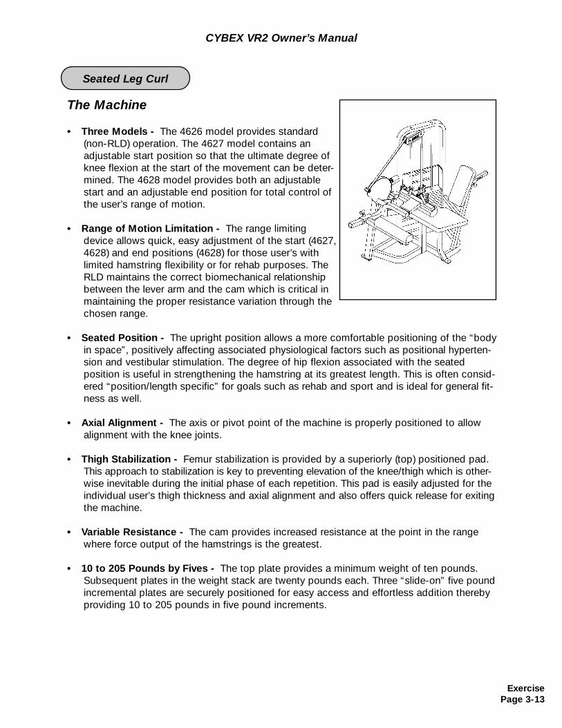
The Machine
• Three Models - The 4626 model provides standard (non-RLD) operation. The 4627 model contains an adjustable start position so that the ultimate degree ofknee flexion at the start of the movement can be deter-mined. The 4628 model provides both an adjustable start and an adjustable end position for total control of the user’s range of motion.
• Range of Motion Limitation - The range limiting device allows quick, easy adjustment of the start (4627,4628) and end positions (4628) for those user’s with limited hamstring flexibility or for rehab purposes. TheRLD maintains the correct biomechanical relationship between the lever arm and the cam which is critical inmaintaining the proper resistance variation through thechosen range.
• Seated Position - The upright position allows a more comfortable positioning of the “bodyin space”, positively affecting associated physiological factors such as positional hyperten-sion and vestibular stimulation. The degree of hip flexion associated with the seated position is useful in strengthening the hamstring at its greatest length. This is often consid-ered “position/length specific” for goals such as rehab and sport and is ideal for general fit-ness as well.
• Axial Alignment - The axis or pivot point of the machine is properly positioned to allow alignment with the knee joints.
• Thigh Stabilization - Femur stabilization is provided by a superiorly (top) positioned pad. This approach to stabilization is key to preventing elevation of the knee/thigh which is other-wise inevitable during the initial phase of each repetition. This pad is easily adjusted for the individual user’s thigh thickness and axial alignment and also offers quick release for exiting the machine.
• Variable Resistance - The cam provides increased resistance at the point in the range where force output of the hamstrings is the greatest.
• 10 to 205 Pounds by Fives - The top plate provides a minimum weight of ten pounds. Subsequent plates in the weight stack are twenty pounds each. Three “slide-on” five pound incremental plates are securely positioned for easy access and effortless addition thereby providing 10 to 205 pounds in five pound increments.
CYBEX VR2 Owner’s Manual
ExercisePage 3-13
Seated Leg Curl
The Hamstring
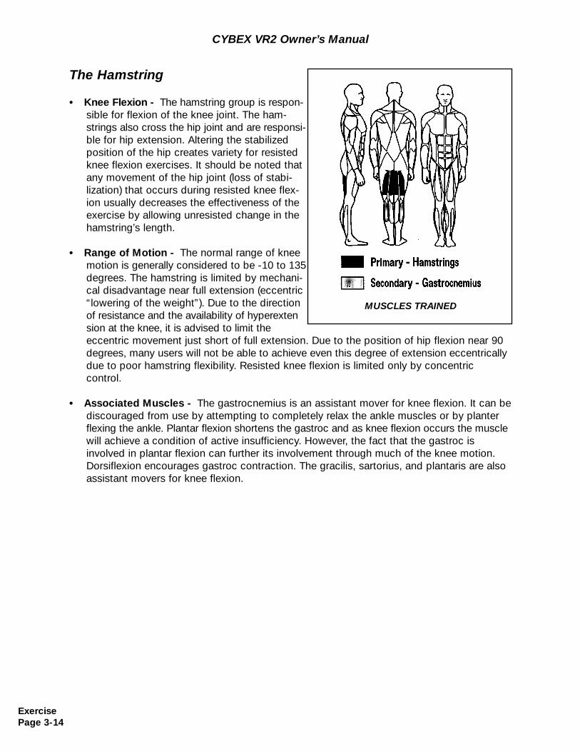
• Knee Flexion - The hamstring group is respon-sible for flexion of the knee joint. The ham-strings also cross the hip joint and are responsi-ble for hip extension. Altering the stabilized position of the hip creates variety for resisted knee flexion exercises. It should be noted that any movement of the hip joint (loss of stabi-lization) that occurs during resisted knee flex-ion usually decreases the effectiveness of the exercise by allowing unresisted change in the hamstring’s length.
• Range of Motion - The normal range of knee motion is generally considered to be -10 to 135 degrees. The hamstring is limited by mechani-cal disadvantage near full extension (eccentric“lowering of the weight”). Due to the direction of resistance and the availability of hyperextension at the knee, it is advised to limit the eccentric movement just short of full extension. Due to the position of hip flexion near 90degrees, many users will not be able to achieve even this degree of extension eccentricallydue to poor hamstring flexibility. Resisted knee flexion is limited only by concentric control.
• Associated Muscles - The gastrocnemius is an assistant mover for knee flexion. It can be discouraged from use by attempting to completely relax the ankle muscles or by planter flexing the ankle. Plantar flexion shortens the gastroc and as knee flexion occurs the muscle will achieve a condition of active insufficiency. However, the fact that the gastroc is involved in plantar flexion can further its involvement through much of the knee motion. Dorsiflexion encourages gastroc contraction. The gracilis, sartorius, and plantaris are also assistant movers for knee flexion.
MUSCLES TRAINED
CYBEX VR2 Owner’s Manual
ExercisePage 3-14
CYBEX VR2 Owner’s Manual
The Motion
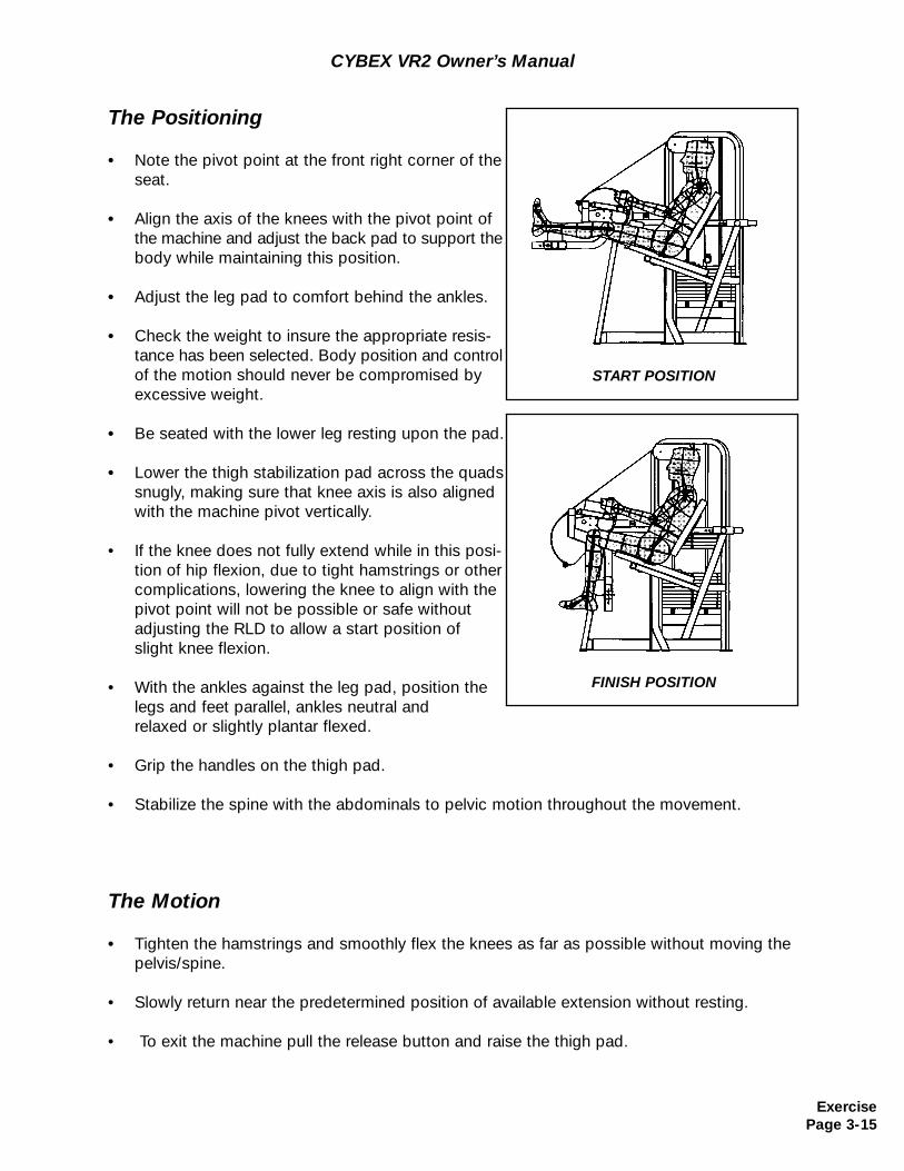
• Tighten the hamstrings and smoothly flex the knees as far as possible without moving the pelvis/spine.
• Slowly return near the predetermined position of available extension without resting.
• To exit the machine pull the release button and raise the thigh pad.
The Positioning
• Note the pivot point at the front right corner of the seat.
• Align the axis of the knees with the pivot point of the machine and adjust the back pad to support the body while maintaining this position.
• Adjust the leg pad to comfort behind the ankles.
• Check the weight to insure the appropriate resis-tance has been selected. Body position and control of the motion should never be compromised by excessive weight.
• Be seated with the lower leg resting upon the pad.
• Lower the thigh stabilization pad across the quads snugly, making sure that knee axis is also aligned with the machine pivot vertically.
• If the knee does not fully extend while in this posi-tion of hip flexion, due to tight hamstrings or othercomplications, lowering the knee to align with the pivot point will not be possible or safe without adjusting the RLD to allow a start position ofslight knee flexion.
• With the ankles against the leg pad, position the legs and feet parallel, ankles neutral and relaxed or slightly plantar flexed.
• Grip the handles on the thigh pad.
• Stabilize the spine with the abdominals to pelvic motion throughout the movement.
START POSITION
FINISH POSITION
ExercisePage 3-15
CYBEX VR2 Owner’s Manual
The Positioning
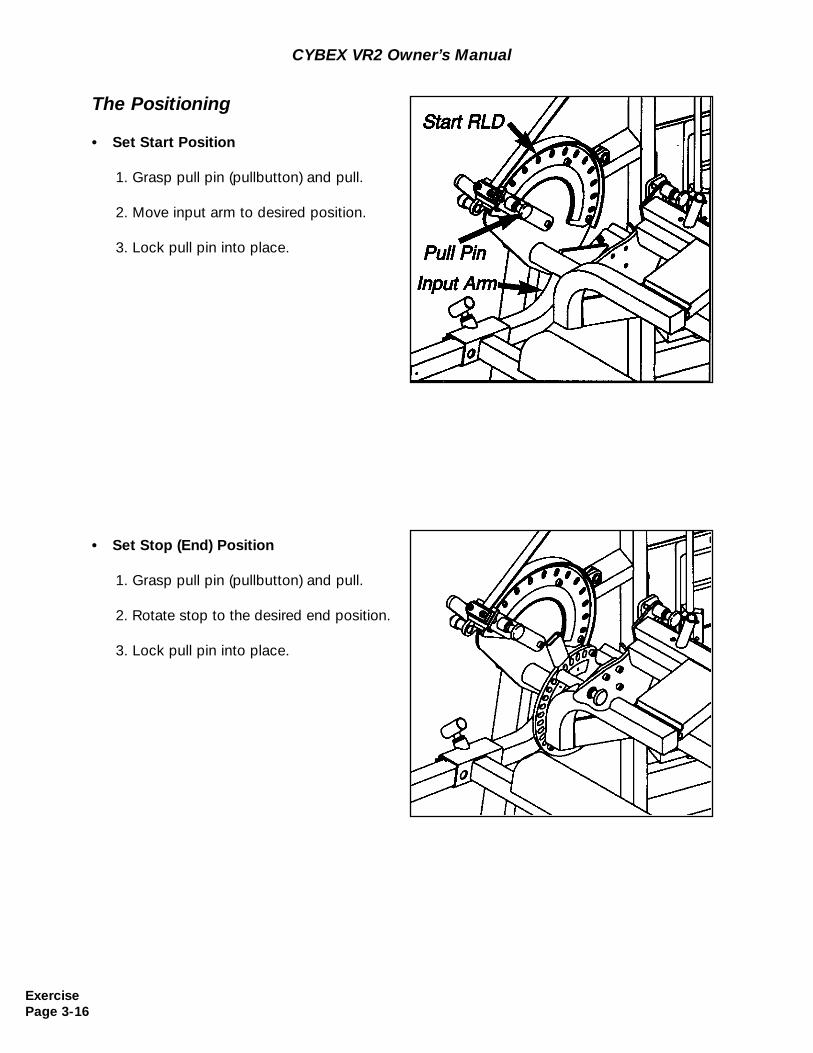
• Set Start Position
1. Grasp pull pin (pullbutton) and pull.
2. Move input arm to desired position.
3. Lock pull pin into place.
• Set Stop (End) Position
1. Grasp pull pin (pullbutton) and pull.
2. Rotate stop to the desired end position.
3. Lock pull pin into place.
ExercisePage 3-16
The Machine
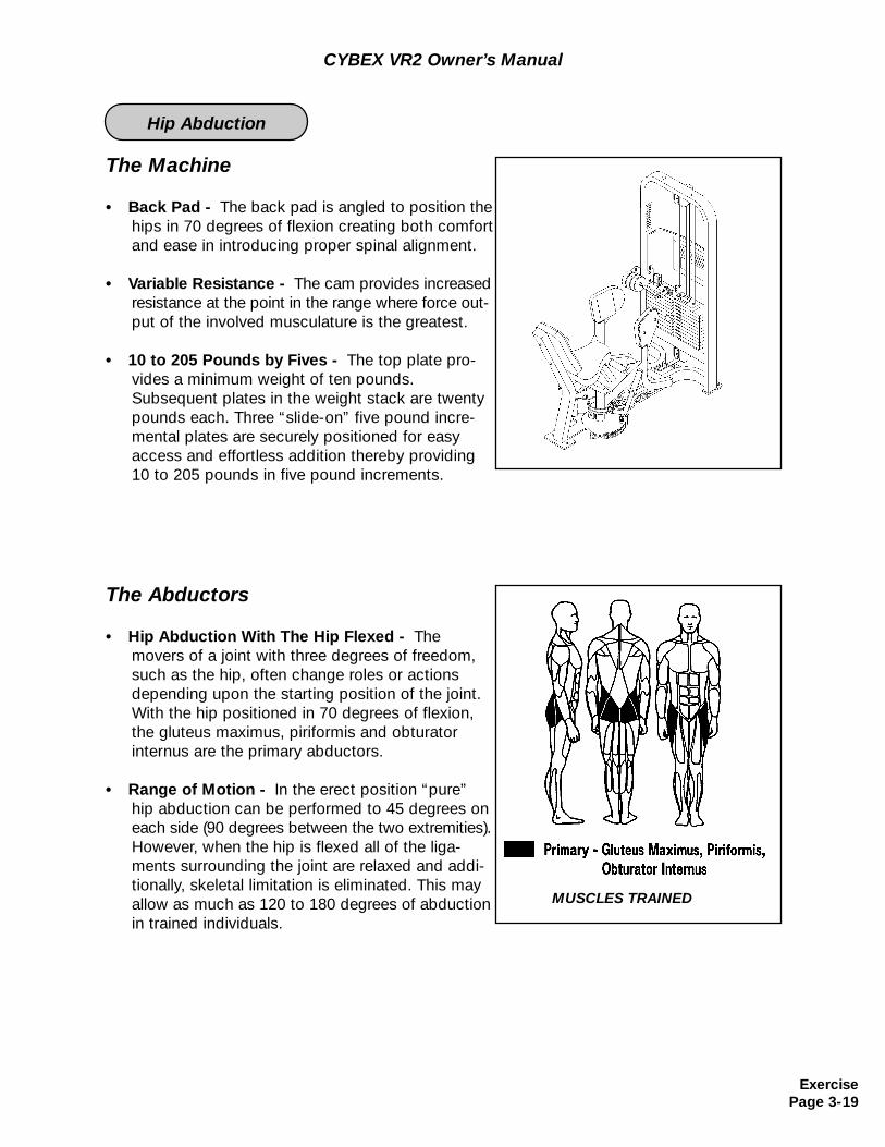
• Back Pad - The back pad is angled to position the\hips in 70 degrees of flexion creating both comfort and ease in introducing proper spinal alignment.
• Variable Resistance - The cam provides increased resistance at the point in the range where force out-put of the involved musculature is the greatest.
• 10 to 205 Pounds by Fives - The top plate pro-vides a minimum weight of ten pounds. Subsequent plates in the weight stack are twenty pounds each. Three “slide-on” five pound incre-mental plates are securely positioned for easy access and effortless addition thereby providing 10 to 205 pounds in five pound incre-ments.
The Abductors
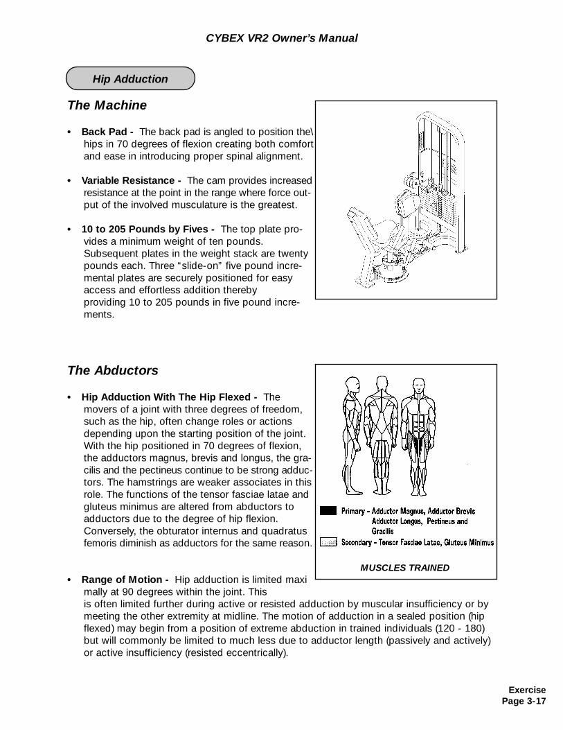
• Hip Adduction With The Hip Flexed - The movers of a joint with three degrees of freedom, such as the hip, often change roles or actions depending upon the starting position of the joint. With the hip positioned in 70 degrees of flexion, the adductors magnus, brevis and longus, the gra-cilis and the pectineus continue to be strong adduc-tors. The hamstrings are weaker associates in this role. The functions of the tensor fasciae latae and gluteus minimus are altered from abductors to adductors due to the degree of hip flexion. Conversely, the obturator internus and quadratus femoris diminish as adductors for the same reason.
• Range of Motion - Hip adduction is limited maximally at 90 degrees within the joint. Thisis often limited further during active or resisted adduction by muscular insufficiency or by meeting the other extremity at midline. The motion of adduction in a sealed position (hip flexed) may begin from a position of extreme abduction in trained individuals (120 - 180) but will commonly be limited to much less due to adductor length (passively and actively) or active insufficiency (resisted eccentrically).
MUSCLES TRAINED
CYBEX VR2 Owner’s Manual
ExercisePage 3-17
Hip Adduction
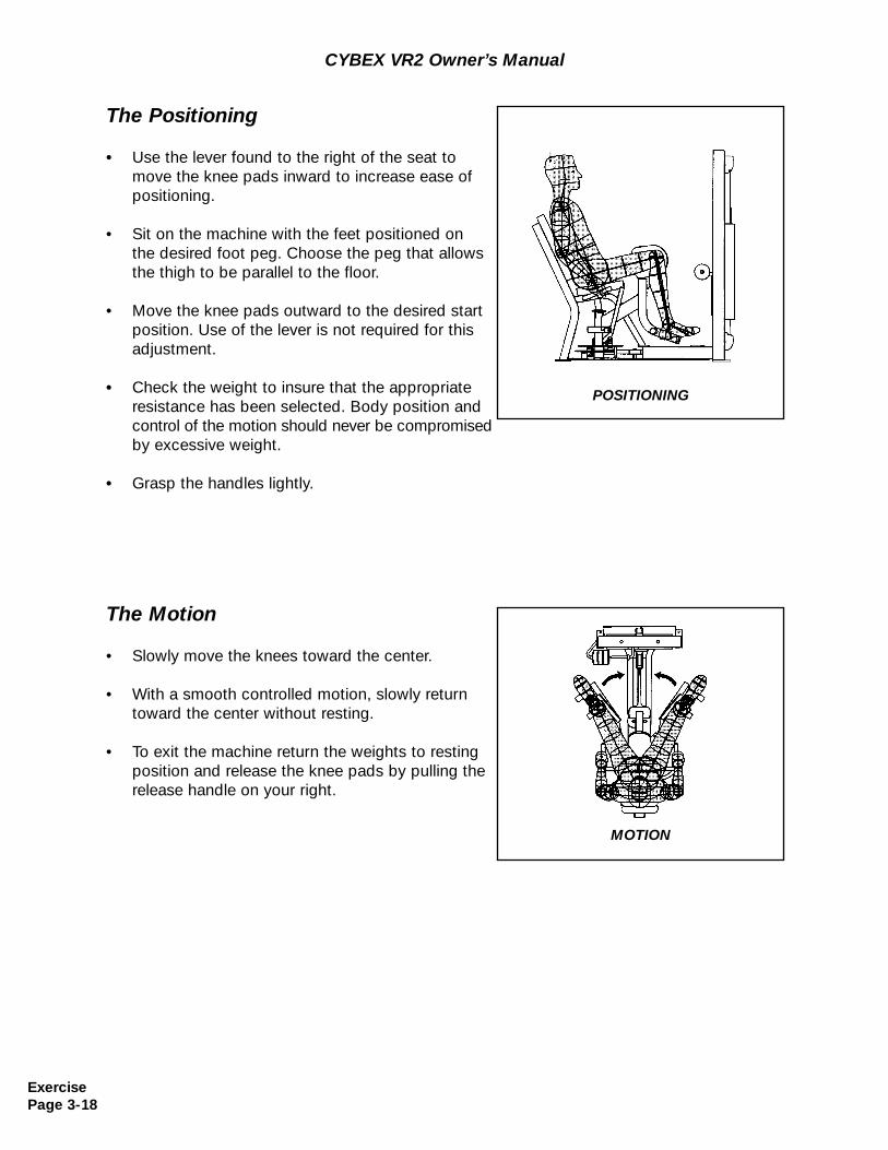
The Positioning
• Use the lever found to the right of the seat to move the knee pads inward to increase ease of positioning.
• Sit on the machine with the feet positioned on the desired foot peg. Choose the peg that allows the thigh to be parallel to the floor.
• Move the knee pads outward to the desired start position. Use of the lever is not required for this adjustment.
• Check the weight to insure that the appropriate resistance has been selected. Body position and control of the motion should never be compromisedby excessive weight.
• Grasp the handles lightly.
The Motion
• Slowly move the knees toward the center.
• With a smooth controlled motion, slowly return toward the center without resting.
• To exit the machine return the weights to resting position and release the knee pads by pulling the release handle on your right.
POSITIONING
MOTION
CYBEX VR2 Owner’s Manual
ExercisePage 3-18
The Machine
• Back Pad - The back pad is angled to position the hips in 70 degrees of flexion creating both comfort and ease in introducing proper spinal alignment.
• Variable Resistance - The cam provides increased resistance at the point in the range where force out-put of the involved musculature is the greatest.
• 10 to 205 Pounds by Fives - The top plate pro-vides a minimum weight of ten pounds. Subsequent plates in the weight stack are twenty pounds each. Three “slide-on” five pound incre-mental plates are securely positioned for easy access and effortless addition thereby providing 10 to 205 pounds in five pound increments.
The Abductors
• Hip Abduction With The Hip Flexed - The movers of a joint with three degrees of freedom, such as the hip, often change roles or actions depending upon the starting position of the joint. With the hip positioned in 70 degrees of flexion, the gluteus maximus, piriformis and obturator internus are the primary abductors.
• Range of Motion - In the erect position “pure” hip abduction can be performed to 45 degrees on each side (90 degrees between the two extremities).However, when the hip is flexed all of the liga-ments surrounding the joint are relaxed and addi-tionally, skeletal limitation is eliminated. This may allow as much as 120 to 180 degrees of abduction in trained individuals.
MUSCLES TRAINED
CYBEX VR2 Owner’s Manual
ExercisePage 3-19
Hip Abduction
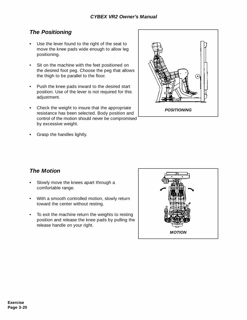
The Positioning
• Use the lever found to the right of the seat to move the knee pads wide enough to allow leg positioning.
• Sit on the machine with the feet positioned on the desired foot peg. Choose the peg that allows the thigh to be parallel to the floor.
• Push the knee pads inward to the desired start position. Use of the lever is not required for this adjustment.
• Check the weight to insure that the appropriate resistance has been selected. Body position and control of the motion should never be compromisedby excessive weight.
• Grasp the handles lightly.
The Motion
• Slowly move the knees apart through a comfortable range.
• With a smooth controlled motion, slowly return toward the center without resting.
• To exit the machine return the weights to resting position and release the knee pads by pulling the release handle on your right.
POSITIONING
MOTION
CYBEX VR2 Owner’s Manual
ExercisePage 3-20
The Machine
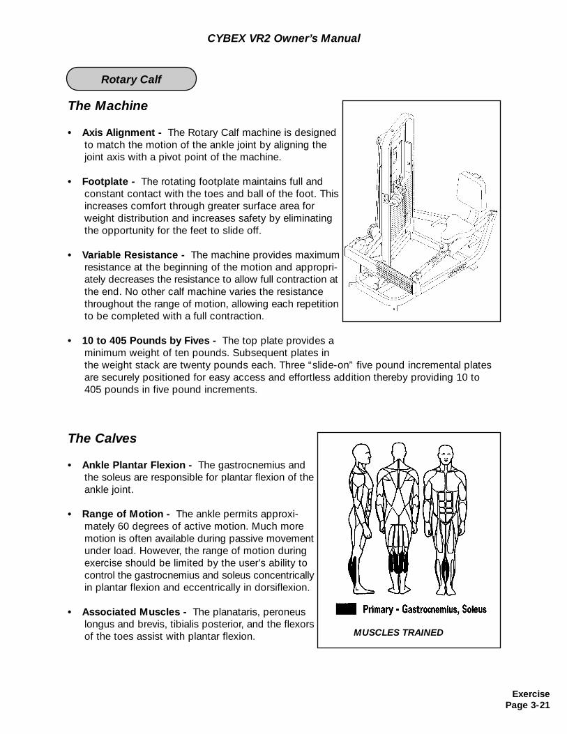
• Axis Alignment - The Rotary Calf machine is designed to match the motion of the ankle joint by aligning the joint axis with a pivot point of the machine.
• Footplate - The rotating footplate maintains full andconstant contact with the toes and ball of the foot. This increases comfort through greater surface area for weight distribution and increases safety by eliminating the opportunity for the feet to slide off.
• Variable Resistance - The machine provides maximum resistance at the beginning of the motion and appropri-ately decreases the resistance to allow full contraction atthe end. No other calf machine varies the resistance throughout the range of motion, allowing each repetition to be completed with a full contraction.
• 10 to 405 Pounds by Fives - The top plate provides a minimum weight of ten pounds. Subsequent plates inthe weight stack are twenty pounds each. Three “slide-on” five pound incremental plates are securely positioned for easy access and effortless addition thereby providing 10 to 405 pounds in five pound increments.
The Calves
• Ankle Plantar Flexion - The gastrocnemius and the soleus are responsible for plantar flexion of the ankle joint.
• Range of Motion - The ankle permits approxi-mately 60 degrees of active motion. Much more motion is often available during passive movement under load. However, the range of motion during exercise should be limited by the user’s ability to control the gastrocnemius and soleus concentrically in plantar flexion and eccentrically in dorsiflexion.
• Associated Muscles - The planataris, peroneus longus and brevis, tibialis posterior, and the flexors of the toes assist with plantar flexion.
CYBEX VR2 Owner’s Manual
MUSCLES TRAINED
ExercisePage 3-21
Rotary Calf
CYBEX VR2 Owner’s Manual
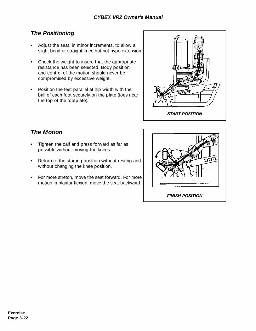
The Positioning
• Adjust the seat, in minor increments, to allow a slight bend or straight knee but not hyperextension.
• Check the weight to insure that the appropriate resistance has been selected. Body position and control of the motion should never be compromised by excessive weight.
• Position the feet parallel at hip width with theball of each foot securely on the plate (toes near the top of the footplate).
The Motion
• Tighten the calf and press forward as far as possible without moving the knees.
• Return to the starting position without resting and without changing the knee position.
• For more stretch, move the seat forward. For more motion in plantar flexion, move the seat backward.
START POSITION
FINISH POSITION
ExercisePage 3-22
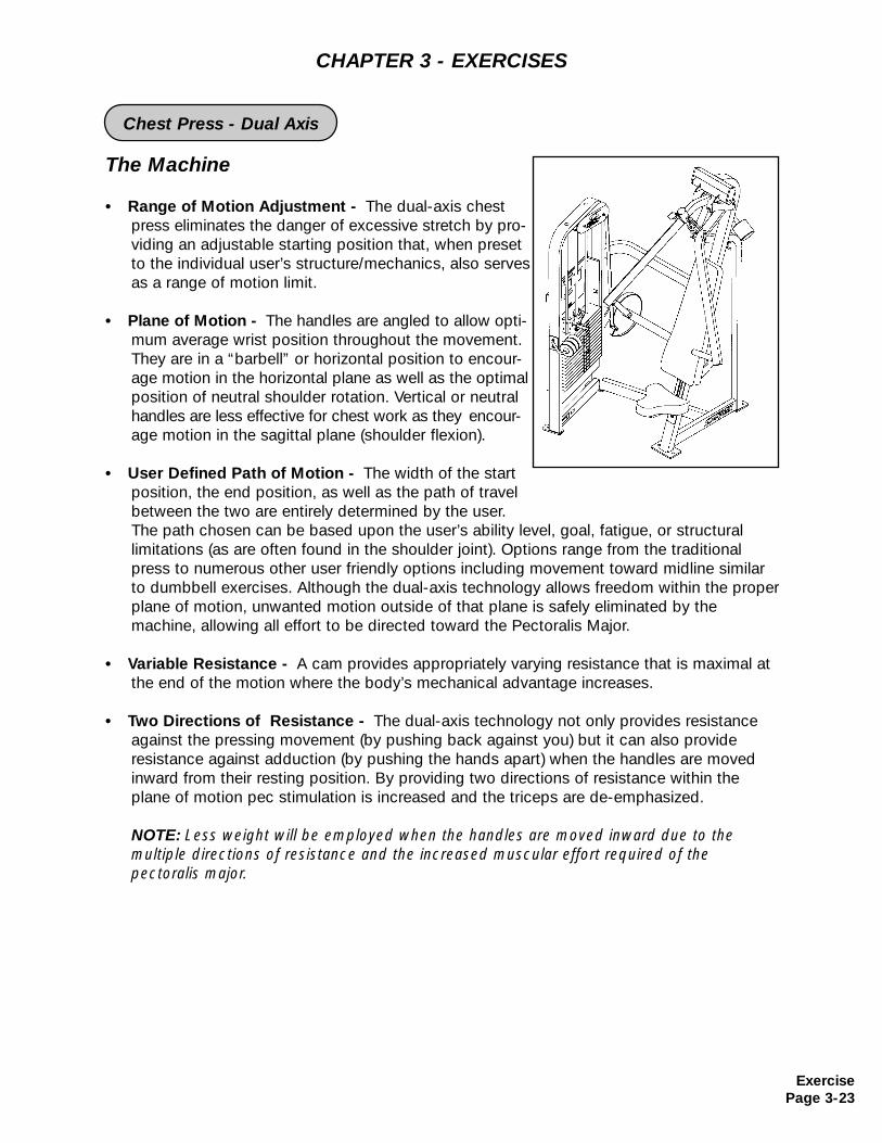
The Machine
• Range of Motion Adjustment - The dual-axis chestpress eliminates the danger of excessive stretch by pro-viding an adjustable starting position that, when presetto the individual user’s structure/mechanics, also servesas a range of motion limit.
• Plane of Motion - The handles are angled to allow opti-mum average wrist position throughout the movement.They are in a “barbell” or horizontal position to encour-age motion in the horizontal plane as well as the optimal position of neutral shoulder rotation. Vertical or neutral handles are less effective for chest work as they encour-age motion in the sagittal plane (shoulder flexion).
• User Defined Path of Motion - The width of the start position, the end position, as well as the path of travel between the two are entirely determined by the user. The path chosen can be based upon the user’s ability level, goal, fatigue, or structurallimitations (as are often found in the shoulder joint). Options range from the traditional press to numerous other user friendly options including movement toward midline similar to dumbbell exercises. Although the dual-axis technology allows freedom within the proper plane of motion, unwanted motion outside of that plane is safely eliminated by the machine, allowing all effort to be directed toward the Pectoralis Major.
• Variable Resistance - A cam provides appropriately varying resistance that is maximal atthe end of the motion where the body’s mechanical advantage increases.
• Two Directions of Resistance - The dual-axis technology not only provides resistance against the pressing movement (by pushing back against you) but it can also provideresistance against adduction (by pushing the hands apart) when the handles are moved inward from their resting position. By providing two directions of resistance within the plane of motion pec stimulation is increased and the triceps are de-emphasized.
NOTE: Less weight will be employed when the handles are moved inward due to the multiple directions of resistance and the increased muscular effort required of thepectoralis major.
CHAPTER 3 - EXERCISES
ExercisePage 3-23
Chest Press - Dual Axis
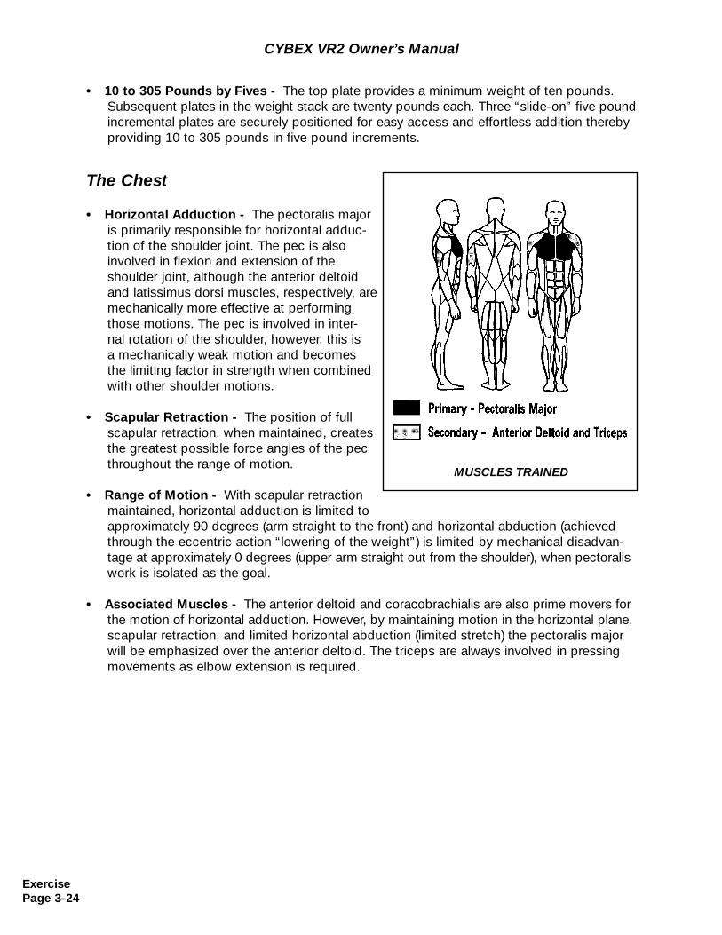
The Chest
• Horizontal Adduction - The pectoralis majoris primarily responsible for horizontal adduc-tion of the shoulder joint. The pec is also involved in flexion and extension of the shoulder joint, although the anterior deltoid and latissimus dorsi muscles, respectively, are mechanically more effective at performing those motions. The pec is involved in inter-nal rotation of the shoulder, however, this isa mechanically weak motion and becomes the limiting factor in strength when combinedwith other shoulder motions.
• Scapular Retraction - The position of full scapular retraction, when maintained, creates the greatest possible force angles of the pecthroughout the range of motion.
• Range of Motion - With scapular retraction maintained, horizontal adduction is limited to approximately 90 degrees (arm straight to the front) and horizontal abduction (achieved through the eccentric action “lowering of the weight”) is limited by mechanical disadvan-tage at approximately 0 degrees (upper arm straight out from the shoulder), when pectoralis work is isolated as the goal.
• Associated Muscles - The anterior deltoid and coracobrachialis are also prime movers forthe motion of horizontal adduction. However, by maintaining motion in the horizontal plane, scapular retraction, and limited horizontal abduction (limited stretch) the pectoralis major will be emphasized over the anterior deltoid. The triceps are always involved in pressing movements as elbow extension is required.
MUSCLES TRAINED
CYBEX VR2 Owner’s Manual
• 10 to 305 Pounds by Fives - The top plate provides a minimum weight of ten pounds. Subsequent plates in the weight stack are twenty pounds each. Three “slide-on” five pound incremental plates are securely positioned for easy access and effortless addition thereby providing 10 to 305 pounds in five pound increments.
ExercisePage 3-24
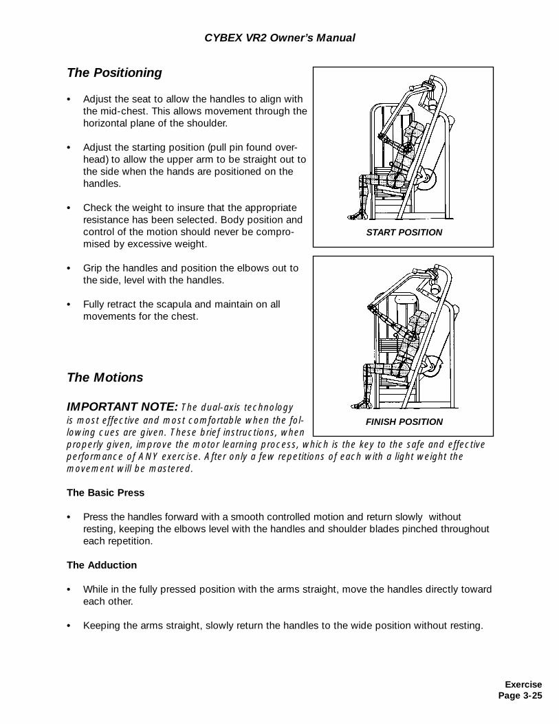
CYBEX VR2 Owner’s Manual
The Positioning
• Adjust the seat to allow the handles to align with the mid-chest. This allows movement through the horizontal plane of the shoulder.
• Adjust the starting position (pull pin found over-head) to allow the upper arm to be straight out to the side when the hands are positioned on thehandles.
• Check the weight to insure that the appropriate resistance has been selected. Body position and control of the motion should never be compro-mised by excessive weight.
• Grip the handles and position the elbows out to the side, level with the handles.
• Fully retract the scapula and maintain on all movements for the chest.
The Motions
IMPORTANT NOTE: The dual-axis technology is most effective and most comfortable when the fol-lowing cues are given. These brief instructions, whenproperly given, improve the motor learning process, which is the key to the safe and effectiveperformance of ANY exercise. After only a few repetitions of each with a light weight themovement will be mastered.
The Basic Press
• Press the handles forward with a smooth controlled motion and return slowly withoutresting, keeping the elbows level with the handles and shoulder blades pinched throughout each repetition.
The Adduction
• While in the fully pressed position with the arms straight, move the handles directly toward each other.
• Keeping the arms straight, slowly return the handles to the wide position without resting.
START POSITION
FINISH POSITION
ExercisePage 3-25
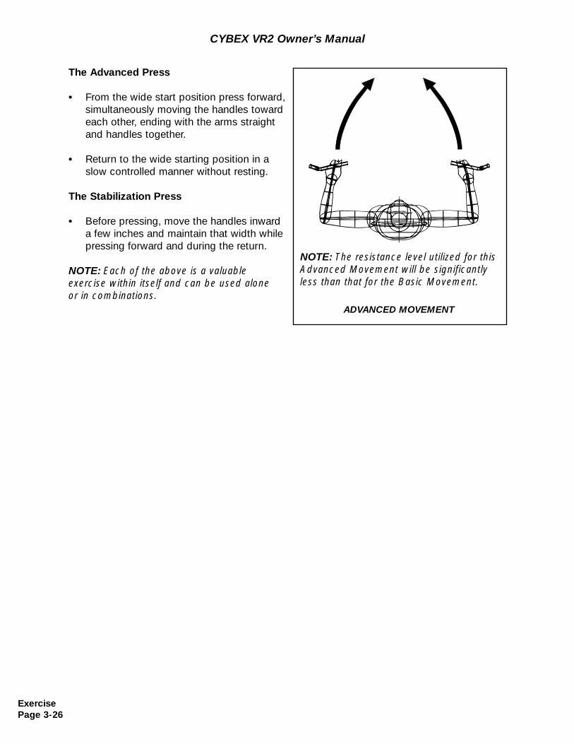
The Advanced Press
• From the wide start position press forward, simultaneously moving the handles toward each other, ending with the arms straightand handles together.
• Return to the wide starting position in a slow controlled manner without resting.
The Stabilization Press
• Before pressing, move the handles inward a few inches and maintain that width while pressing forward and during the return.
NOTE: Each of the above is a valuable exercise within itself and can be used alone or in combinations.
CYBEX VR2 Owner’s Manual
ADVANCED MOVEMENT
NOTE: The resistance level utilized for thisAdvanced Movement will be significantlyless than that for the Basic Movement.
ExercisePage 3-26
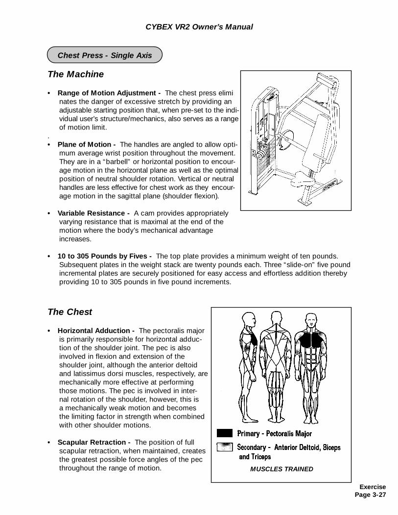
CYBEX VR2 Owner’s Manual
The Machine
• Range of Motion Adjustment - The chest press eliminates the danger of excessive stretch by providing an adjustable starting position that, when pre-set to the indi-vidual user’s structure/mechanics, also serves as a range of motion limit.
. • Plane of Motion - The handles are angled to allow opti-
mum average wrist position throughout the movement.They are in a “barbell” or horizontal position to encour-age motion in the horizontal plane as well as the optimal position of neutral shoulder rotation. Vertical or neutral handles are less effective for chest work as they encour-age motion in the sagittal plane (shoulder flexion).
• Variable Resistance - A cam provides appropriately varying resistance that is maximal at the end of the motion where the body’s mechanical advantage increases.
• 10 to 305 Pounds by Fives - The top plate provides a minimum weight of ten pounds. Subsequent plates in the weight stack are twenty pounds each. Three “slide-on” five pound incremental plates are securely positioned for easy access and effortless addition thereby providing 10 to 305 pounds in five pound increments.
The Chest
• Horizontal Adduction - The pectoralis majoris primarily responsible for horizontal adduc-tion of the shoulder joint. The pec is also involved in flexion and extension of the shoulder joint, although the anterior deltoid and latissimus dorsi muscles, respectively, are mechanically more effective at performing those motions. The pec is involved in inter-nal rotation of the shoulder, however, this isa mechanically weak motion and becomes the limiting factor in strength when combinedwith other shoulder motions.
• Scapular Retraction - The position of full scapular retraction, when maintained, creates the greatest possible force angles of the pecthroughout the range of motion. MUSCLES TRAINED
ExercisePage 3-27
Chest Press - Single Axis
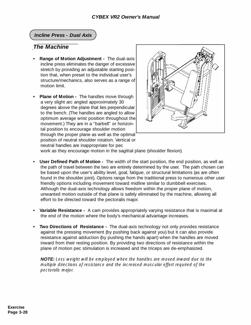
CYBEX VR2 Owner’s Manual
ExercisePage 3-28
The Machine
• Range of Motion Adjustment - The dual-axis incline press eliminates the danger of excessive stretch by providing an adjustable starting posi-tion that, when preset to the individual user’s structure/mechanics, also serves as a range of motion limit.
• Plane of Motion - The handles move through a very slight arc angled approximately 30 degrees above the plane that lies perpendicular to the bench. (The handles are angled to allowoptimum average wrist position throughout themovement.) They are in a “barbell” or horizon-tal position to encourage shoulder motion through the proper plane as well as the optimal position of neutral shoulder rotation. Vertical or neutral handles are inappropriate for pec work as they encourage motion in the sagittal plane (shoulder flexion).
• User Defined Path of Motion - The width of the start position, the end position, as well as the path of travel between the two are entirely determined by the user. The path chosen canbe based upon the user’s ability level, goal, fatigue, or structural limitations (as are often found in the shoulder joint). Options range from the traditional press to numerous other user friendly options including movement toward midline similar to dumbbell exercises. Although the dual-axis technology allows freedom within the proper plane of motion, unwanted motion outside of that plane is safely eliminated by the machine, allowing all effort to be directed toward the pectoralis major.
• Variable Resistance - A cam provides appropriately varying resistance that is maximal atthe end of the motion where the body’s mechanical advantage increases.
• Two Directions of Resistance - The dual-axis technology not only provides resistance against the pressing movement (by pushing back against you) but it can also provideresistance against adduction (by pushing the hands apart) when the handles are moved inward from their resting position. By providing two directions of resistance within the plane of motion pec stimulation is increased and the triceps are de-emphasized.
NOTE: Less weight will be employed when the handles are moved inward due to the multiple directions of resistance and the increased muscular effort required of thepectoralis major.
Incline Press - Dual Axis
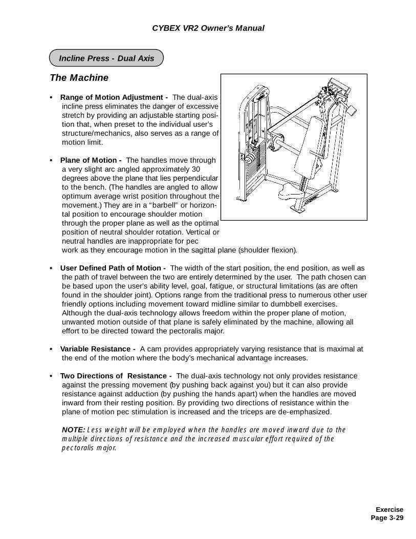
The Machine
• Range of Motion Adjustment - The dual-axis incline press eliminates the danger of excessive stretch by providing an adjustable starting posi-tion that, when preset to the individual user’s structure/mechanics, also serves as a range of motion limit.
• Plane of Motion - The handles move through a very slight arc angled approximately 30 degrees above the plane that lies perpendicular to the bench. (The handles are angled to allowoptimum average wrist position throughout themovement.) They are in a “barbell” or horizon-tal position to encourage shoulder motion through the proper plane as well as the optimal position of neutral shoulder rotation. Vertical or neutral handles are inappropriate for pec work as they encourage motion in the sagittal plane (shoulder flexion).
• User Defined Path of Motion - The width of the start position, the end position, as well as the path of travel between the two are entirely determined by the user. The path chosen canbe based upon the user’s ability level, goal, fatigue, or structural limitations (as are often found in the shoulder joint). Options range from the traditional press to numerous other user friendly options including movement toward midline similar to dumbbell exercises. Although the dual-axis technology allows freedom within the proper plane of motion, unwanted motion outside of that plane is safely eliminated by the machine, allowing all effort to be directed toward the pectoralis major.
• Variable Resistance - A cam provides appropriately varying resistance that is maximal atthe end of the motion where the body’s mechanical advantage increases.
• Two Directions of Resistance - The dual-axis technology not only provides resistance against the pressing movement (by pushing back against you) but it can also provideresistance against adduction (by pushing the hands apart) when the handles are moved inward from their resting position. By providing two directions of resistance within the plane of motion pec stimulation is increased and the triceps are de-emphasized.
NOTE: Less weight will be employed when the handles are moved inward due to the multiple directions of resistance and the increased muscular effort required of thepectoralis major.
CYBEX VR2 Owner’s Manual
ExercisePage 3-29
Incline Press - Dual Axis
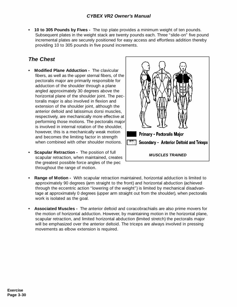
The Chest
• Modified Plane Adduction - The clavicular fibers, as well as the upper sternal fibers, of the pectoralis major are primarily responsible for adduction of the shoulder through a plane angled approximately 30 degrees above the horizontal plane of the shoulder joint. The pec-toralis major is also involved in flexion and extension of the shoulder joint, although the anterior deltoid and latissimus dorsi muscles, respectively, are mechanically more effective at performing those motions. The pectoralis major is involved in internal rotation of the shoulder,however, this is a mechanically weak motion and becomes the limiting factor in strength when combined with other shoulder motions.
• Scapular Retraction - The position of full scapular retraction, when maintained, creates the greatest possible force angles of the pecthroughout the range of motion.
• Range of Motion - With scapular retraction maintained, horizontal adduction is limited to approximately 90 degrees (arm straight to the front) and horizontal abduction (achieved through the eccentric action “lowering of the weight”) is limited by mechanical disadvan-tage at approximately 0 degrees (upper arm straight out from the shoulder), when pectoralis work is isolated as the goal.
• Associated Muscles - The anterior deltoid and coracobrachialis are also prime movers forthe motion of horizontal adduction. However, by maintaining motion in the horizontal plane, scapular retraction, and limited horizontal abduction (limited stretch) the pectoralis major will be emphasized over the anterior deltoid. The triceps are always involved in pressing movements as elbow extension is required.
MUSCLES TRAINED
CYBEX VR2 Owner’s Manual
• 10 to 305 Pounds by Fives - The top plate provides a minimum weight of ten pounds. Subsequent plates in the weight stack are twenty pounds each. Three “slide-on” five pound incremental plates are securely positioned for easy access and effortless addition thereby providing 10 to 305 pounds in five pound increments.
ExercisePage 3-30
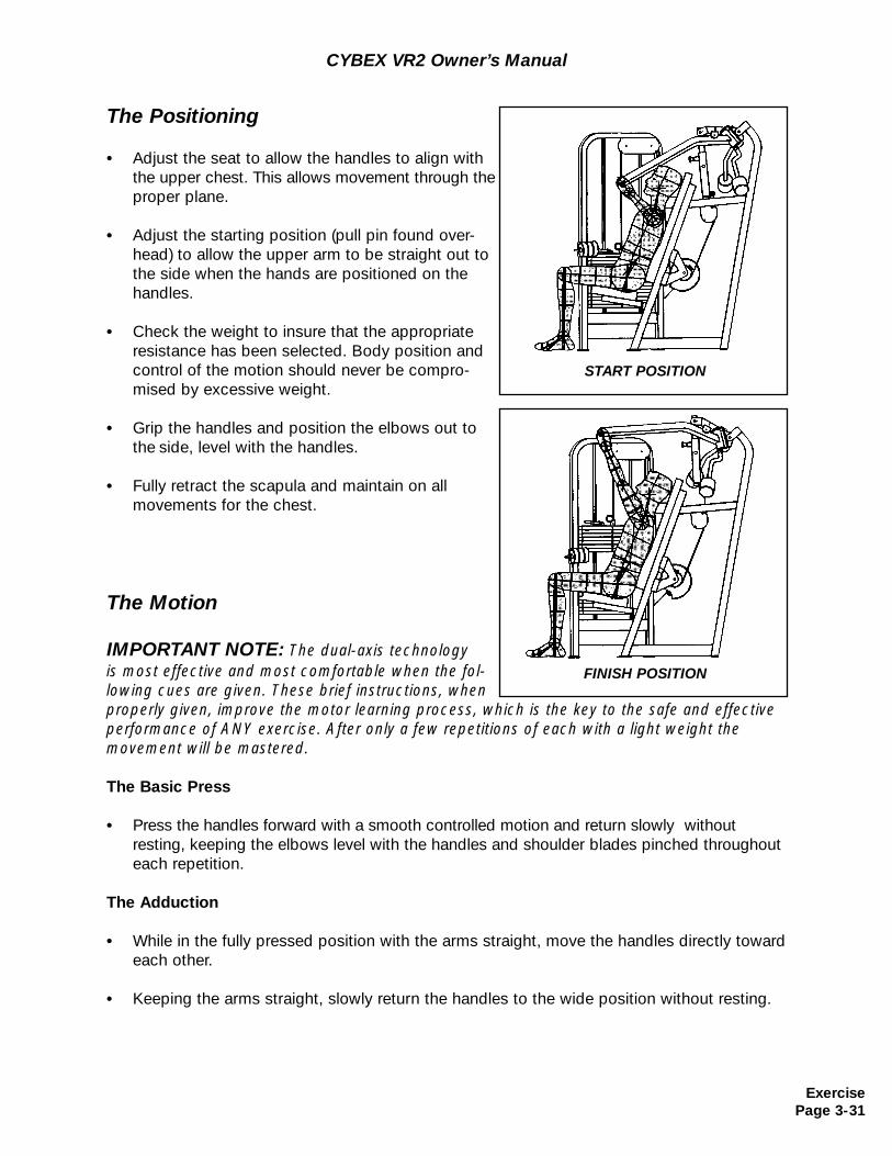
CYBEX VR2 Owner’s Manual
The Positioning
• Adjust the seat to allow the handles to align with the upper chest. This allows movement through the proper plane.
• Adjust the starting position (pull pin found over-head) to allow the upper arm to be straight out to the side when the hands are positioned on thehandles.
• Check the weight to insure that the appropriate resistance has been selected. Body position and control of the motion should never be compro-mised by excessive weight.
• Grip the handles and position the elbows out to the side, level with the handles.
• Fully retract the scapula and maintain on all movements for the chest.
The Motion
IMPORTANT NOTE: The dual-axis technology is most effective and most comfortable when the fol-lowing cues are given. These brief instructions, whenproperly given, improve the motor learning process, which is the key to the safe and effectiveperformance of ANY exercise. After only a few repetitions of each with a light weight themovement will be mastered.
The Basic Press
• Press the handles forward with a smooth controlled motion and return slowly withoutresting, keeping the elbows level with the handles and shoulder blades pinched throughout each repetition.
The Adduction
• While in the fully pressed position with the arms straight, move the handles directly toward each other.
• Keeping the arms straight, slowly return the handles to the wide position without resting.
START POSITION
FINISH POSITION
ExercisePage 3-31
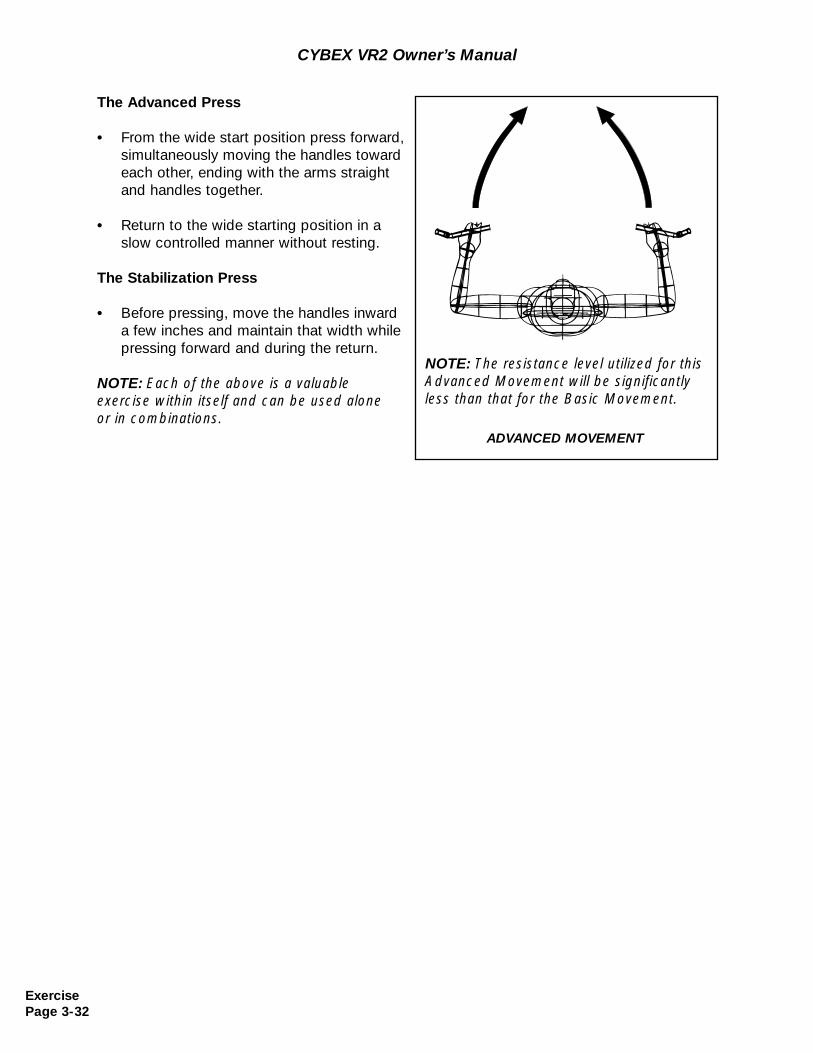
The Advanced Press
• From the wide start position press forward, simultaneously moving the handles toward each other, ending with the arms straightand handles together.
• Return to the wide starting position in a slow controlled manner without resting.
The Stabilization Press
• Before pressing, move the handles inward a few inches and maintain that width while pressing forward and during the return.
NOTE: Each of the above is a valuable exercise within itself and can be used alone or in combinations.
CYBEX VR2 Owner’s Manual
ADVANCED MOVEMENT
NOTE: The resistance level utilized for thisAdvanced Movement will be significantlyless than that for the Basic Movement.
ExercisePage 3-32
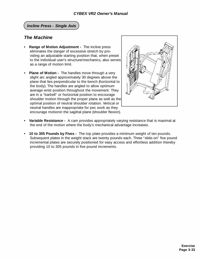
The Machine
• Range of Motion Adjustment - The incline press eliminates the danger of excessive stretch by pro-viding an adjustable starting position that, when presetto the individual user’s structure/mechanics, also servesas a range of motion limit.
• Plane of Motion - The handles move through a very slight arc angled approximately 30 degrees above the plane that lies perpendicular to the bench (horizontal to the body). The handles are angled to allow optimum average wrist position throughout the movement. They are in a “barbell” or horizontal position to encourage shoulder motion through the proper plane as well as the optimal position of neutral shoulder rotation. Vertical or neutral handles are inappropriate for pec work as they encourage motionin the sagittal plane (shoulder flexion).
• Variable Resistance - A cam provides appropriately varying resistance that is maximal atthe end of the motion where the body’s mechanical advantage increases.
• 10 to 305 Pounds by Fives - The top plate provides a minimum weight of ten pounds. Subsequent plates in the weight stack are twenty pounds each. Three “slide-on” five pound incremental plates are securely positioned for easy access and effortless addition thereby providing 10 to 305 pounds in five pound increments.
CYBEX VR2 Owner’s Manual
ExercisePage 3-33
Incline Press - Single Axis
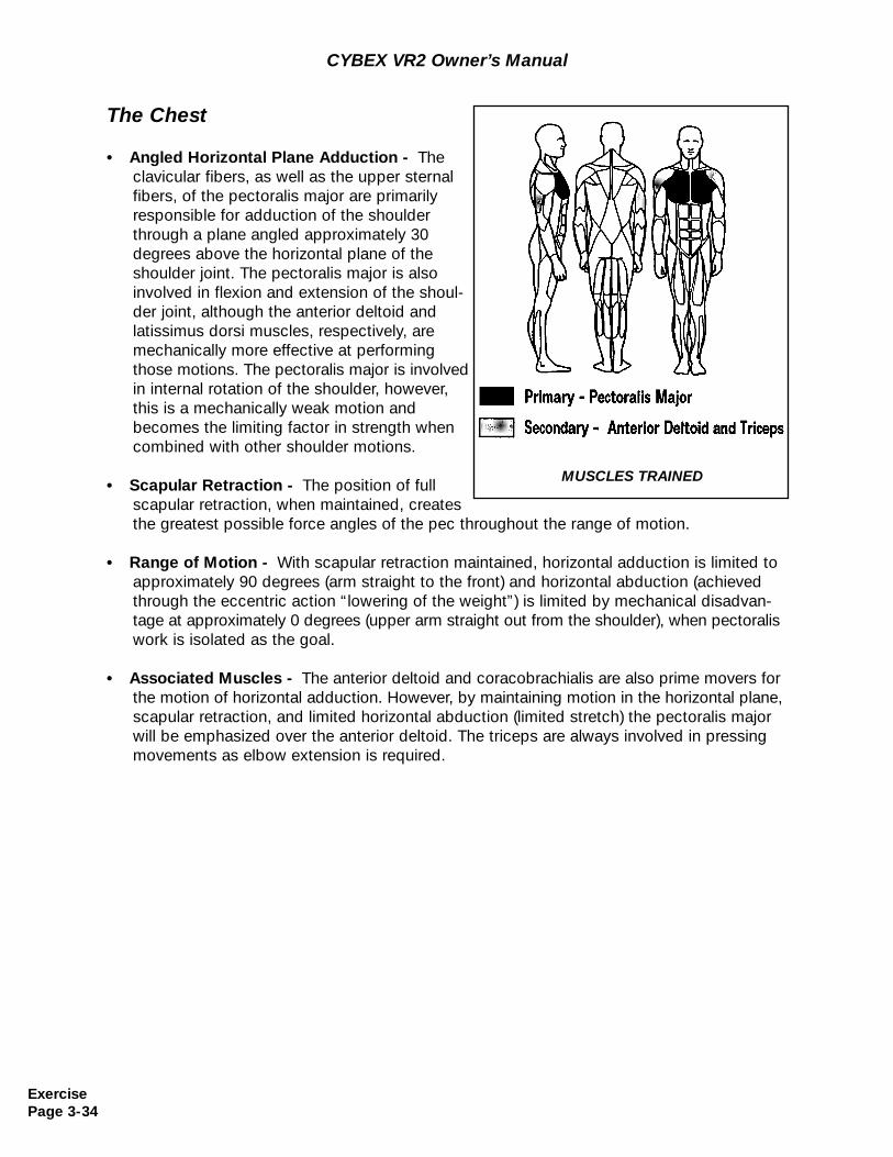
The Chest
• Angled Horizontal Plane Adduction - The clavicular fibers, as well as the upper sternal fibers, of the pectoralis major are primarilyresponsible for adduction of the shoulder through a plane angled approximately 30 degrees above the horizontal plane of the shoulder joint. The pectoralis major is also involved in flexion and extension of the shoul-der joint, although the anterior deltoid and latissimus dorsi muscles, respectively, are mechanically more effective at performing those motions. The pectoralis major is involved in internal rotation of the shoulder, however, this is a mechanically weak motion and becomes the limiting factor in strength whencombined with other shoulder motions.
• Scapular Retraction - The position of full scapular retraction, when maintained, creates the greatest possible force angles of the pec throughout the range of motion.
• Range of Motion - With scapular retraction maintained, horizontal adduction is limited to approximately 90 degrees (arm straight to the front) and horizontal abduction (achieved through the eccentric action “lowering of the weight”) is limited by mechanical disadvan-tage at approximately 0 degrees (upper arm straight out from the shoulder), when pectoralis work is isolated as the goal.
• Associated Muscles - The anterior deltoid and coracobrachialis are also prime movers forthe motion of horizontal adduction. However, by maintaining motion in the horizontal plane, scapular retraction, and limited horizontal abduction (limited stretch) the pectoralis major will be emphasized over the anterior deltoid. The triceps are always involved in pressing movements as elbow extension is required.
MUSCLES TRAINED
CYBEX VR2 Owner’s Manual
ExercisePage 3-34
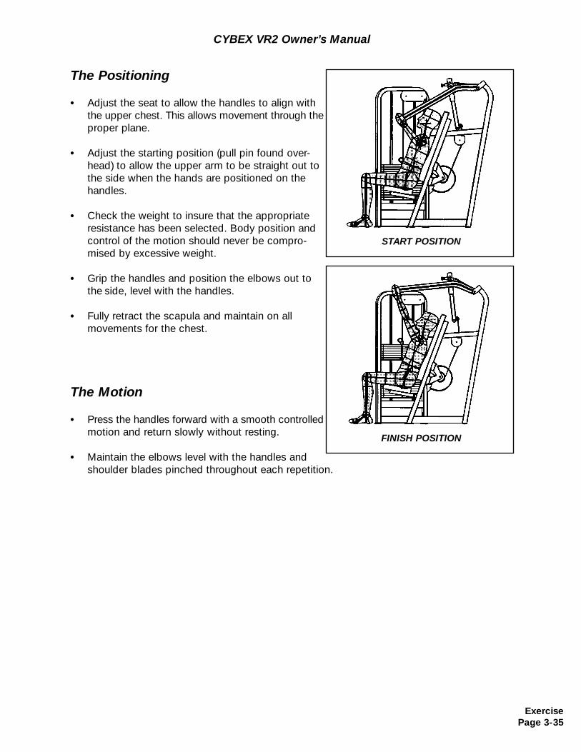
CYBEX VR2 Owner’s Manual
The Positioning
• Adjust the seat to allow the handles to align with the upper chest. This allows movement through the proper plane.
• Adjust the starting position (pull pin found over-head) to allow the upper arm to be straight out to the side when the hands are positioned on thehandles.
• Check the weight to insure that the appropriate resistance has been selected. Body position and control of the motion should never be compro-mised by excessive weight.
• Grip the handles and position the elbows out to the side, level with the handles.
• Fully retract the scapula and maintain on all movements for the chest.
The Motion
• Press the handles forward with a smooth controlled motion and return slowly without resting.
• Maintain the elbows level with the handles and shoulder blades pinched throughout each repetition.
START POSITION
FINISH POSITION
ExercisePage 3-35

CYBEX VR2 Owner’s Manual
(This page intentionally left blank)
ExercisePage 3-36
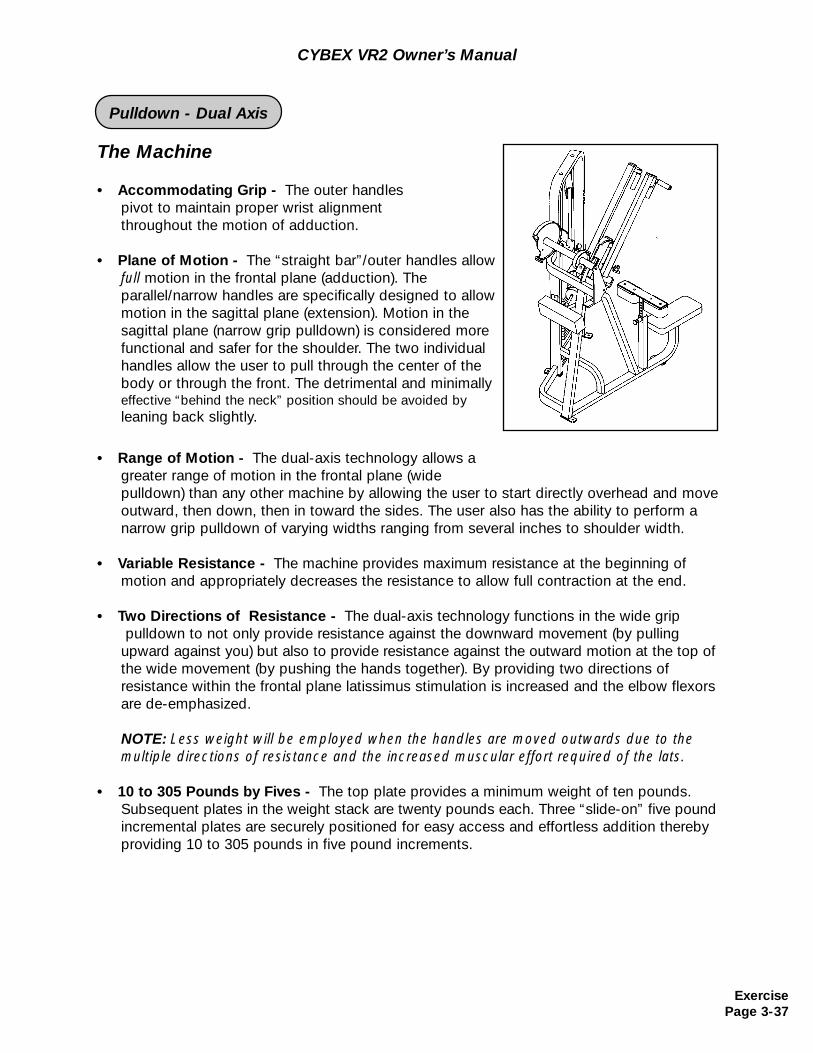
The Machine
• Accommodating Grip - The outer handles pivot to maintain proper wrist alignment throughout the motion of adduction.
• Plane of Motion - The “straight bar”/outer handles allow full motion in the frontal plane (adduction). The parallel/narrow handles are specifically designed to allow motion in the sagittal plane (extension). Motion in thesagittal plane (narrow grip pulldown) is considered morefunctional and safer for the shoulder. The two individual handles allow the user to pull through the center of the body or through the front. The detrimental and minimally effective “behind the neck” position should be avoided byleaning back slightly.
• Range of Motion - The dual-axis technology allows a greater range of motion in the frontal plane (widepulldown) than any other machine by allowing the user to start directly overhead and move outward, then down, then in toward the sides. The user also has the ability to perform a narrow grip pulldown of varying widths ranging from several inches to shoulder width.
• Variable Resistance - The machine provides maximum resistance at the beginning ofmotion and appropriately decreases the resistance to allow full contraction at the end.
• Two Directions of Resistance - The dual-axis technology functions in the wide grippulldown to not only provide resistance against the downward movement (by pulling
upward against you) but also to provide resistance against the outward motion at the top of the wide movement (by pushing the hands together). By providing two directions ofresistance within the frontal plane latissimus stimulation is increased and the elbow flexorsare de-emphasized.
NOTE: Less weight will be employed when the handles are moved outwards due to the multiple directions of resistance and the increased muscular effort required of the lats.
• 10 to 305 Pounds by Fives - The top plate provides a minimum weight of ten pounds. Subsequent plates in the weight stack are twenty pounds each. Three “slide-on” five pound incremental plates are securely positioned for easy access and effortless addition thereby providing 10 to 305 pounds in five pound increments.
CYBEX VR2 Owner’s Manual
ExercisePage 3-37
Pulldown - Dual Axis
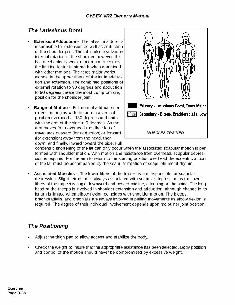
The Latissimus Dorsi
• Extension/Adduction - The latissimus dorsi is responsible for extension as well as adduction of the shoulder joint. The lat is also involved in internal rotation of the shoulder, however, this is a mechanically weak motion and becomes the limiting factor in strength when combined with other motions. The teres major works alongside the upper fibers of the lat in adduc-tion and extension. The combined positions of external rotation to 90 degrees and abductionto 90 degrees create the most compromising position for the shoulder joint.
• Range of Motion - Full normal adduction orextension begins with the arm in a vertical position overhead at 180 degrees and ends with the arm at the side in 0 degrees. As the arm moves from overhead the direction of travel arcs outward (for adduction) or forward(for extension) away from the head, then down, and finally, inward toward the side. Full concentric shortening of the lat can only occur when the associated scapular motion is performed with shoulder motion. With motion and resistance from overhead, scapular depres-sion is required. For the arm to return to the starting position overhead the eccentric actionof the lat must be accompanied by the scapular rotation of scapulohumeral rhythm.
• Associated Muscles - The lower fibers of the trapezius are responsible for scapular depression. Slight retraction is always associated with scapular depression as the lower fibers of the trapezius angle downward and toward midline, attaching on the spine. The longhead of the triceps is involved in shoulder extension and adduction, although change in its length is limited when elbow flexion coincides with shoulder motion. The biceps, brachioradialis, and brachialis are always involved in pulling movements as elbow flexion isrequired. The degree of their individual involvement depends upon radioulner joint position.
MUSCLES TRAINED
CYBEX VR2 Owner’s Manual
The Positioning
• Adjust the thigh pad to allow access and stabilize the body.
• Check the weight to insure that the appropriate resistance has been selected. Body position and control of the motion should never be compromised by excessive weight.
ExercisePage 3-38
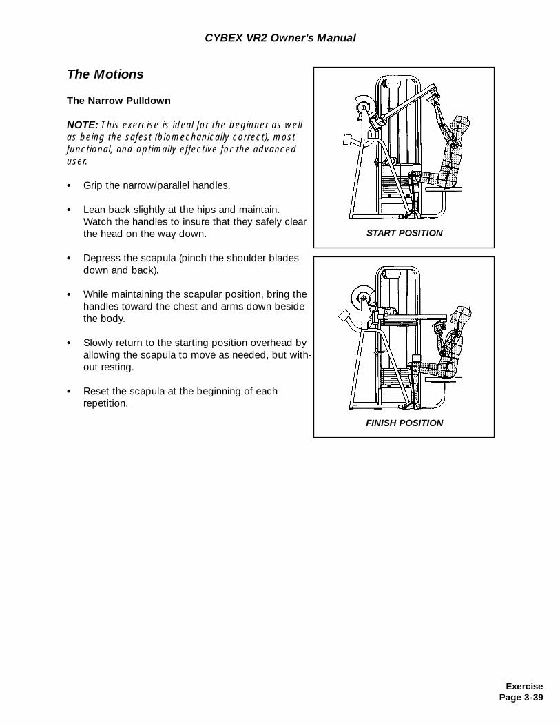
CYBEX VR2 Owner’s Manual
The Motions
The Narrow Pulldown
NOTE: This exercise is ideal for the beginner as wellas being the safest (biomechanically correct), mostfunctional, and optimally effective for the advanceduser.
• Grip the narrow/parallel handles.
• Lean back slightly at the hips and maintain. Watch the handles to insure that they safely clear the head on the way down.
• Depress the scapula (pinch the shoulder blades down and back).
• While maintaining the scapular position, bring the handles toward the chest and arms down beside the body.
• Slowly return to the starting position overhead by allowing the scapula to move as needed, but with-out resting.
• Reset the scapula at the beginning of eachrepetition.
START POSITION
FINISH POSITION
ExercisePage 3-39
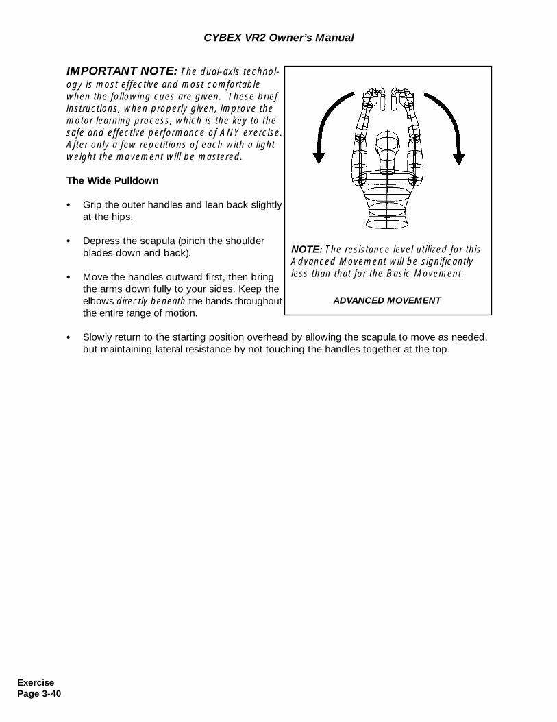
IMPORTANT NOTE: The dual-axis technol-ogy is most effective and most comfortablewhen the following cues are given. These briefinstructions, when properly given, improve themotor learning process, which is the key to thesafe and effective performance of ANY exercise.After only a few repetitions of each with a lightweight the movement will be mastered.
The Wide Pulldown
• Grip the outer handles and lean back slightlyat the hips.
• Depress the scapula (pinch the shoulder blades down and back).
• Move the handles outward first, then bring the arms down fully to your sides. Keep the elbows directly beneath the hands throughout the entire range of motion.
• Slowly return to the starting position overhead by allowing the scapula to move as needed, but maintaining lateral resistance by not touching the handles together at the top.
CYBEX VR2 Owner’s Manual
ADVANCED MOVEMENT
NOTE: The resistance level utilized for thisAdvanced Movement will be significantlyless than that for the Basic Movement.
ExercisePage 3-40
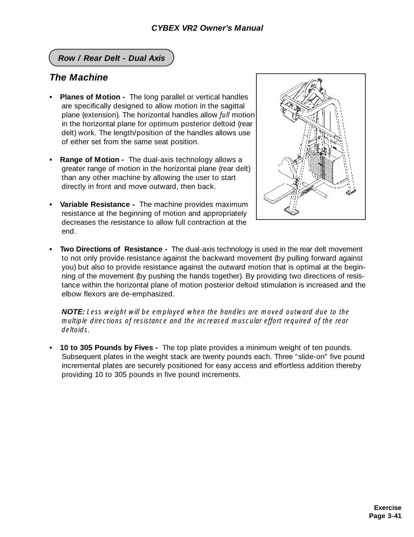
The Machine
• Planes of Motion - The long parallel or vertical handles are specifically designed to allow motion in the sagittal plane (extension). The horizontal handles allow full motionin the horizontal plane for optimum posterior deltoid (rear delt) work. The length/position of the handles allows use of either set from the same seat position.
• Range of Motion - The dual-axis technology allows a greater range of motion in the horizontal plane (rear delt) than any other machine by allowing the user to start directly in front and move outward, then back.
• Variable Resistance - The machine provides maximum resistance at the beginning of motion and appropriately decreases the resistance to allow full contraction at the end.
• Two Directions of Resistance - The dual-axis technology is used in the rear delt movement to not only provide resistance against the backward movement (by pulling forward against you) but also to provide resistance against the outward motion that is optimal at the begin-ning of the movement (by pushing the hands together). By providing two directions of resis-tance within the horizontal plane of motion posterior deltoid stimulation is increased and the elbow flexors are de-emphasized.
NOTE: Less weight will be employed when the handles are moved outward due to the multiple directions of resistance and the increased muscular effort required of the reardeltoids.
• 10 to 305 Pounds by Fives - The top plate provides a minimum weight of ten pounds. Subsequent plates in the weight stack are twenty pounds each. Three “slide-on” five pound incremental plates are securely positioned for easy access and effortless addition thereby providing 10 to 305 pounds in five pound increments.
CYBEX VR2 Owner’s Manual
ExercisePage 3-41
Row / Rear Delt - Dual Axis
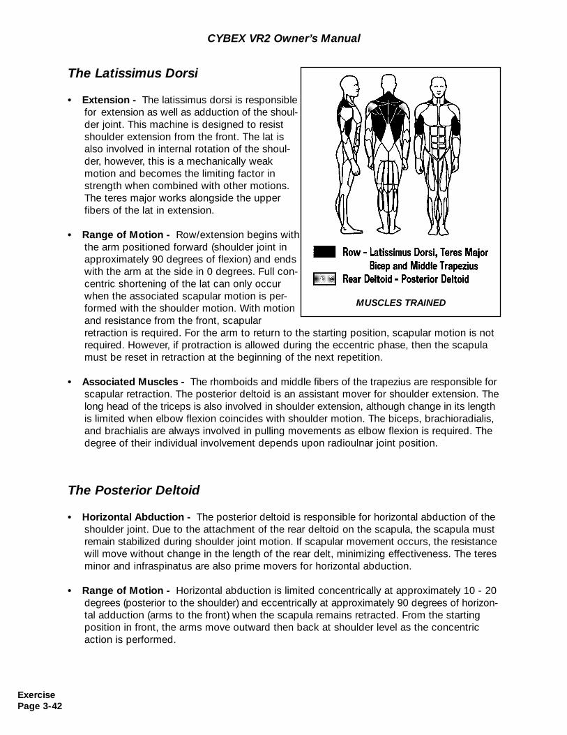
The Latissimus Dorsi
• Extension - The latissimus dorsi is responsible for extension as well as adduction of the shoul-der joint. This machine is designed to resist shoulder extension from the front. The lat is also involved in internal rotation of the shoul-der, however, this is a mechanically weak motion and becomes the limiting factor in strength when combined with other motions. The teres major works alongside the upper fibers of the lat in extension.
• Range of Motion - Row/extension begins withthe arm positioned forward (shoulder joint in approximately 90 degrees of flexion) and ends with the arm at the side in 0 degrees. Full con-centric shortening of the lat can only occur when the associated scapular motion is per-formed with the shoulder motion. With motion and resistance from the front, scapularretraction is required. For the arm to return to the starting position, scapular motion is notrequired. However, if protraction is allowed during the eccentric phase, then the scapulamust be reset in retraction at the beginning of the next repetition.
• Associated Muscles - The rhomboids and middle fibers of the trapezius are responsible for scapular retraction. The posterior deltoid is an assistant mover for shoulder extension. The long head of the triceps is also involved in shoulder extension, although change in its lengthis limited when elbow flexion coincides with shoulder motion. The biceps, brachioradialis, and brachialis are always involved in pulling movements as elbow flexion is required. The degree of their individual involvement depends upon radioulnar joint position.
CYBEX VR2 Owner’s Manual
The Posterior Deltoid
• Horizontal Abduction - The posterior deltoid is responsible for horizontal abduction of theshoulder joint. Due to the attachment of the rear deltoid on the scapula, the scapula must remain stabilized during shoulder joint motion. If scapular movement occurs, the resistance will move without change in the length of the rear delt, minimizing effectiveness. The teresminor and infraspinatus are also prime movers for horizontal abduction.
• Range of Motion - Horizontal abduction is limited concentrically at approximately 10 - 20 degrees (posterior to the shoulder) and eccentrically at approximately 90 degrees of horizon-tal adduction (arms to the front) when the scapula remains retracted. From the starting position in front, the arms move outward then back at shoulder level as the concentric action is performed.
MUSCLES TRAINED
ExercisePage 3-42
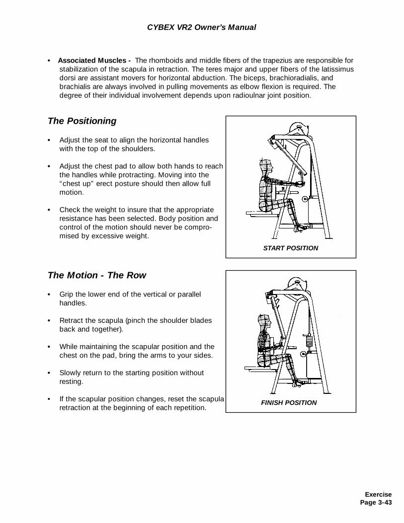
CYBEX VR2 Owner’s Manual
The Positioning
• Adjust the seat to align the horizontal handleswith the top of the shoulders.
• Adjust the chest pad to allow both hands to reach the handles while protracting. Moving into the “chest up” erect posture should then allow full motion.
• Check the weight to insure that the appropriateresistance has been selected. Body position and control of the motion should never be compro-mised by excessive weight.
START POSITION
• Associated Muscles - The rhomboids and middle fibers of the trapezius are responsible for stabilization of the scapula in retraction. The teres major and upper fibers of the latissimus dorsi are assistant movers for horizontal abduction. The biceps, brachioradialis, and brachialis are always involved in pulling movements as elbow flexion is required. The degree of their individual involvement depends upon radioulnar joint position.
The Motion - The Row
• Grip the lower end of the vertical or parallel handles.
• Retract the scapula (pinch the shoulder blades back and together).
• While maintaining the scapular position and the chest on the pad, bring the arms to your sides.
• Slowly return to the starting position withoutresting.
• If the scapular position changes, reset the scapula retraction at the beginning of each repetition.
FINISH POSITION
ExercisePage 3-43
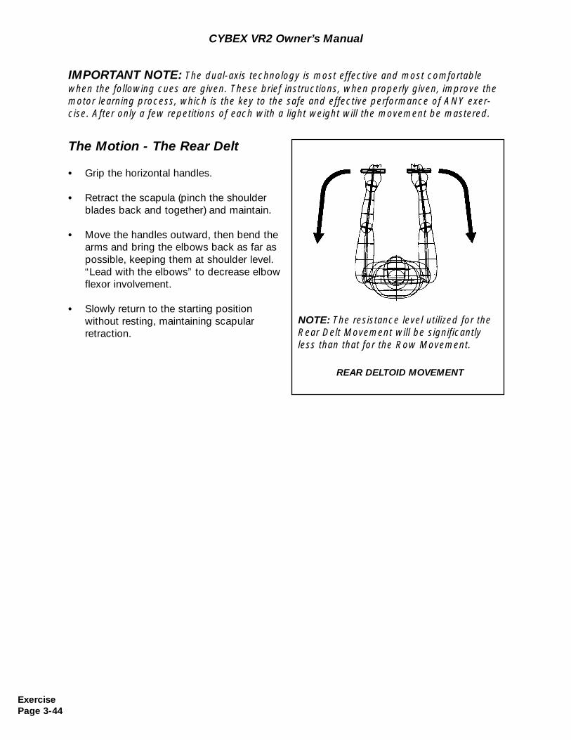
CYBEX VR2 Owner’s Manual
The Motion - The Rear Delt
• Grip the horizontal handles.
• Retract the scapula (pinch the shoulder blades back and together) and maintain.
• Move the handles outward, then bend the arms and bring the elbows back as far aspossible, keeping them at shoulder level. “Lead with the elbows” to decrease elbow flexor involvement.
• Slowly return to the starting position without resting, maintaining scapularretraction.
REAR DELTOID MOVEMENT
NOTE: The resistance level utilized for theRear Delt Movement will be significantlyless than that for the Row Movement.
IMPORTANT NOTE: The dual-axis technology is most effective and most comfortablewhen the following cues are given. These brief instructions, when properly given, improve themotor learning process, which is the key to the safe and effective performance of ANY exer-cise. After only a few repetitions of each with a light weight will the movement be mastered.
ExercisePage 3-44
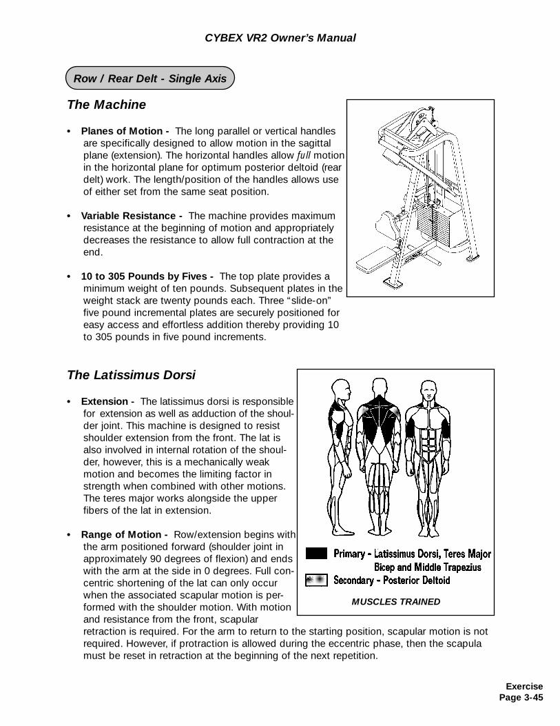
The Machine
• Planes of Motion - The long parallel or vertical handles are specifically designed to allow motion in the sagittal plane (extension). The horizontal handles allow full motionin the horizontal plane for optimum posterior deltoid (rear delt) work. The length/position of the handles allows use of either set from the same seat position.
• Variable Resistance - The machine provides maximum resistance at the beginning of motion and appropriately decreases the resistance to allow full contraction at the end.
• 10 to 305 Pounds by Fives - The top plate provides a minimum weight of ten pounds. Subsequent plates in the weight stack are twenty pounds each. Three “slide-on” five pound incremental plates are securely positioned for easy access and effortless addition thereby providing 10 to 305 pounds in five pound increments.
CYBEX VR2 Owner’s Manual
The Latissimus Dorsi
• Extension - The latissimus dorsi is responsible for extension as well as adduction of the shoul-der joint. This machine is designed to resist shoulder extension from the front. The lat is also involved in internal rotation of the shoul-der, however, this is a mechanically weak motion and becomes the limiting factor in strength when combined with other motions. The teres major works alongside the upper fibers of the lat in extension.
• Range of Motion - Row/extension begins withthe arm positioned forward (shoulder joint in approximately 90 degrees of flexion) and ends with the arm at the side in 0 degrees. Full con-centric shortening of the lat can only occur when the associated scapular motion is per-formed with the shoulder motion. With motion and resistance from the front, scapularretraction is required. For the arm to return to the starting position, scapular motion is notrequired. However, if protraction is allowed during the eccentric phase, then the scapulamust be reset in retraction at the beginning of the next repetition.
MUSCLES TRAINED
ExercisePage 3-45
Row / Rear Delt - Single Axis
• Associated Muscles - The rhomboids and middle fibers of the trapezius are responsible for scapular retraction. The posterior deltoid is an assistant mover for shoulder extension. The long head of the triceps is also involved in shoulder extension, although change in its lengthis limited when elbow flexion coincides with shoulder motion. The biceps, brachioradialis, and brachialis are always involved in pulling movements as elbow flexion is required. The degree of their individual involvement depends upon radioulnar joint position.
CYBEX VR2 Owner’s Manual
The Posterior Deltoid
• Horizontal Abduction - The posterior deltoid is responsible for horizontal abduction of theshoulder joint. Due to the attachment of the rear deltoid on the scapula, the scapula must remain stabilized during shoulder joint motion. If scapular movement occurs, the resistance will move without change in the length of the rear delt, minimizing effectiveness. The teresminor and infraspinatus are also prime movers for horizontal abduction.
• Range of Motion - Horizontal abduction is limited concentrically at approximately 10 - 20 degrees (posterior to the shoulder) and eccentrically at approximately 90 degrees of horizon-tal adduction (arms to the front) when the scapula remains retracted.
• Associated Muscles - The rhomboids and middle fibers of the trapezius are responsible for stabilization of the scapula in retraction. The teres major and upper fibers of the latissimus dorsi are assistant movers for horizontal abduction. The biceps, brachioradialis, and brachialis are always involved in pulling movements as elbow flexion is required. The degree of their individual involvement depends upon radioulnar joint position.
ExercisePage 3-46
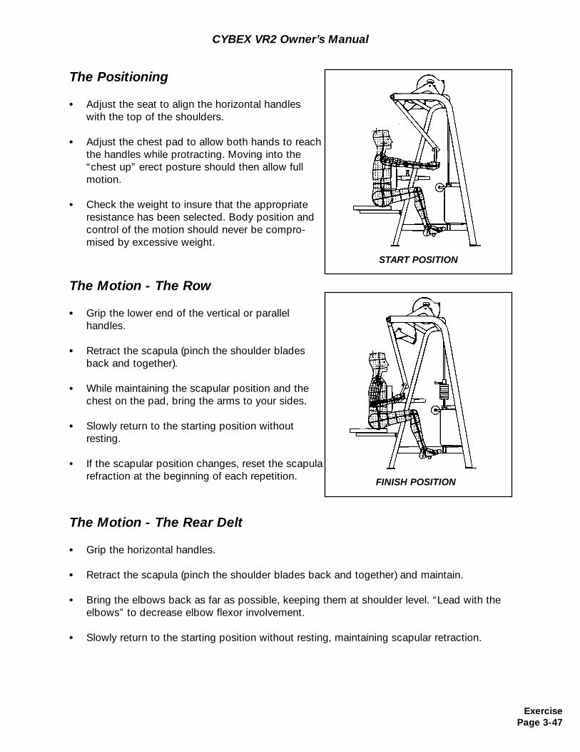
CYBEX VR2 Owner’s Manual
The Positioning
• Adjust the seat to align the horizontal handleswith the top of the shoulders.
• Adjust the chest pad to allow both hands to reach the handles while protracting. Moving into the “chest up” erect posture should then allow full motion.
• Check the weight to insure that the appropriateresistance has been selected. Body position and control of the motion should never be compro-mised by excessive weight.
START POSITION
The Motion - The Row
• Grip the lower end of the vertical or parallel handles.
• Retract the scapula (pinch the shoulder blades back and together).
• While maintaining the scapular position and the chest on the pad, bring the arms to your sides.
• Slowly return to the starting position withoutresting.
• If the scapular position changes, reset the scapula refraction at the beginning of each repetition. FINISH POSITION
The Motion - The Rear Delt
• Grip the horizontal handles.
• Retract the scapula (pinch the shoulder blades back and together) and maintain.
• Bring the elbows back as far as possible, keeping them at shoulder level. “Lead with the elbows” to decrease elbow flexor involvement.
• Slowly return to the starting position without resting, maintaining scapular retraction.
ExercisePage 3-47
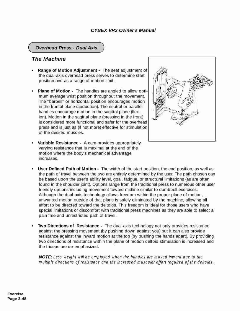
CYBEX VR2 Owner’s Manual
The Machine
• Range of Motion Adjustment - The seat adjustment ofthe dual-axis overhead press serves to determine start position and as a range of motion limit.
• Plane of Motion - The handles are angled to allow opti-mum average wrist position throughout the movement.The “barbell” or horizontal position encourages motionin the frontal plane (abduction). The neutral or parallel handles encourage motion in the sagittal plane (flex-ion). Motion in the sagittal plane (pressing in the front)is considered more functional and safer for the overhead press and is just as (if not more) effective for stimulation of the desired muscles.
• Variable Resistance - A cam provides appropriately varying resistance that is maximal at the end of the motion where the body’s mechanical advantage increases.
• User Defined Path of Motion - The width of the start position, the end position, as well as the path of travel between the two are entirely determined by the user. The path chosen canbe based upon the user’s ability level, goal, fatigue, or structural limitations (as are often found in the shoulder joint). Options range from the traditional press to numerous other user friendly options including movement toward midline similar to dumbbell exercises. Although the dual-axis technology allows freedom within the proper plane of motion, unwanted motion outside of that plane is safely eliminated by the machine, allowing all effort to be directed toward the deltoids. This freedom is ideal for those users who have special limitations or discomfort with traditional press machines as they are able to select a pain free and unrestricted path of travel.
• Two Directions of Resistance - The dual-axis technology not only provides resistance against the pressing movement (by pushing down against you) but it can also provide resistance against the inward motion at the top (by pushing the hands apart). By providing two directions of resistance within the plane of motion deltoid stimulation is increased and the triceps are de-emphasized.
NOTE: Less weight will be employed when the handles are moved inward due to the multiple directions of resistance and the increased muscular effort required of the deltoids.
ExercisePage 3-48
Overhead Press - Dual Axis
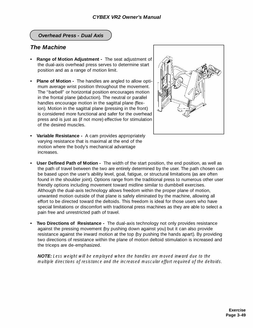
The Machine
• Range of Motion Adjustment - The seat adjustment ofthe dual-axis overhead press serves to determine start position and as a range of motion limit.
• Plane of Motion - The handles are angled to allow opti-mum average wrist position throughout the movement.The “barbell” or horizontal position encourages motionin the frontal plane (abduction). The neutral or parallel handles encourage motion in the sagittal plane (flex-ion). Motion in the sagittal plane (pressing in the front)is considered more functional and safer for the overhead press and is just as (if not more) effective for stimulation of the desired muscles.
• Variable Resistance - A cam provides appropriately varying resistance that is maximal at the end of the motion where the body’s mechanical advantage increases.
• User Defined Path of Motion - The width of the start position, the end position, as well as the path of travel between the two are entirely determined by the user. The path chosen canbe based upon the user’s ability level, goal, fatigue, or structural limitations (as are often found in the shoulder joint). Options range from the traditional press to numerous other user friendly options including movement toward midline similar to dumbbell exercises. Although the dual-axis technology allows freedom within the proper plane of motion, unwanted motion outside of that plane is safely eliminated by the machine, allowing all effort to be directed toward the deltoids. This freedom is ideal for those users who have special limitations or discomfort with traditional press machines as they are able to select a pain free and unrestricted path of travel.
• Two Directions of Resistance - The dual-axis technology not only provides resistance against the pressing movement (by pushing down against you) but it can also provide resistance against the inward motion at the top (by pushing the hands apart). By providing two directions of resistance within the plane of motion deltoid stimulation is increased and the triceps are de-emphasized.
NOTE: Less weight will be employed when the handles are moved inward due to the multiple directions of resistance and the increased muscular effort required of the deltoids.
CYBEX VR2 Owner’s Manual
ExercisePage 3-49
Overhead Press - Dual Axis
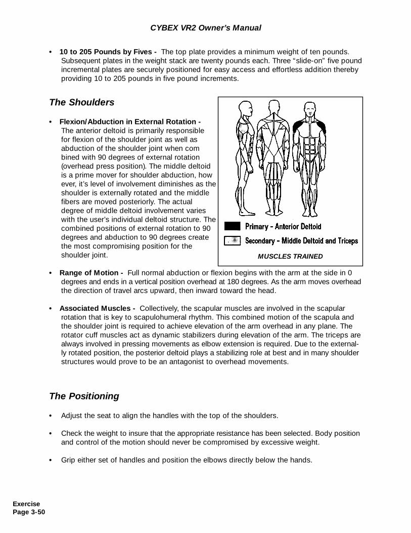
CYBEX VR2 Owner’s Manual
• 10 to 205 Pounds by Fives - The top plate provides a minimum weight of ten pounds. Subsequent plates in the weight stack are twenty pounds each. Three “slide-on” five pound incremental plates are securely positioned for easy access and effortless addition thereby providing 10 to 205 pounds in five pound increments.
The Shoulders
• Flexion/Abduction in External Rotation - The anterior deltoid is primarily responsible for flexion of the shoulder joint as well as abduction of the shoulder joint when combined with 90 degrees of external rotation (overhead press position). The middle deltoid is a prime mover for shoulder abduction, however, it’s level of involvement diminishes as the shoulder is externally rotated and the middle fibers are moved posteriorly. The actual degree of middle deltoid involvement varies with the user’s individual deltoid structure. The combined positions of external rotation to 90 degrees and abduction to 90 degrees create the most compromising position for theshoulder joint.
• Range of Motion - Full normal abduction or flexion begins with the arm at the side in 0 degrees and ends in a vertical position overhead at 180 degrees. As the arm moves overhead the direction of travel arcs upward, then inward toward the head.
• Associated Muscles - Collectively, the scapular muscles are involved in the scapular rotation that is key to scapulohumeral rhythm. This combined motion of the scapula and the shoulder joint is required to achieve elevation of the arm overhead in any plane. Therotator cuff muscles act as dynamic stabilizers during elevation of the arm. The triceps are always involved in pressing movements as elbow extension is required. Due to the external-ly rotated position, the posterior deltoid plays a stabilizing role at best and in many shoulder structures would prove to be an antagonist to overhead movements.
The Positioning
• Adjust the seat to align the handles with the top of the shoulders.
• Check the weight to insure that the appropriate resistance has been selected. Body position and control of the motion should never be compromised by excessive weight.
• Grip either set of handles and position the elbows directly below the hands.
MUSCLES TRAINED
ExercisePage 3-50
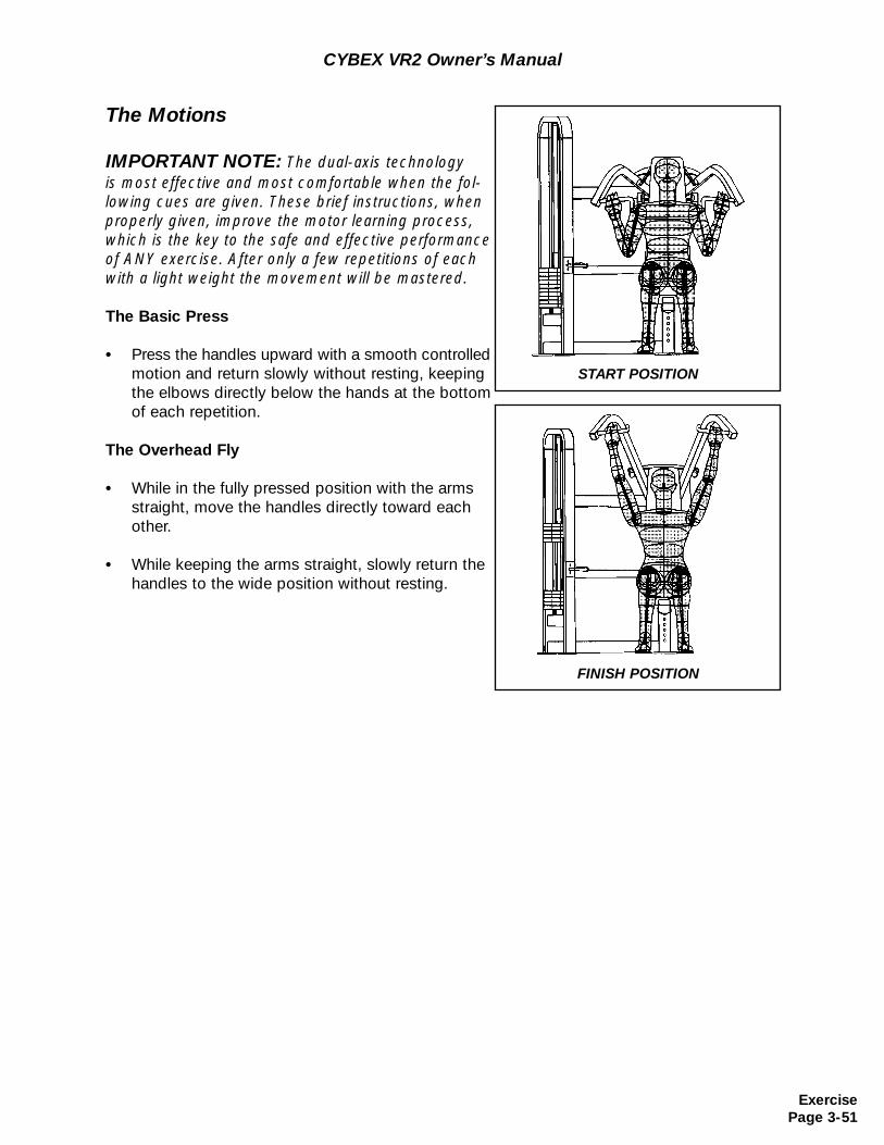
CYBEX VR2 Owner’s Manual
The Motions
IMPORTANT NOTE: The dual-axis technology is most effective and most comfortable when the fol-lowing cues are given. These brief instructions, whenproperly given, improve the motor learning process,which is the key to the safe and effective performanceof ANY exercise. After only a few repetitions of eachwith a light weight the movement will be mastered.
The Basic Press
• Press the handles upward with a smooth controlled motion and return slowly without resting, keeping the elbows directly below the hands at the bottom of each repetition.
The Overhead Fly
• While in the fully pressed position with the arms straight, move the handles directly toward each other.
• While keeping the arms straight, slowly return the handles to the wide position without resting.
START POSITION
FINISH POSITION
ExercisePage 3-51
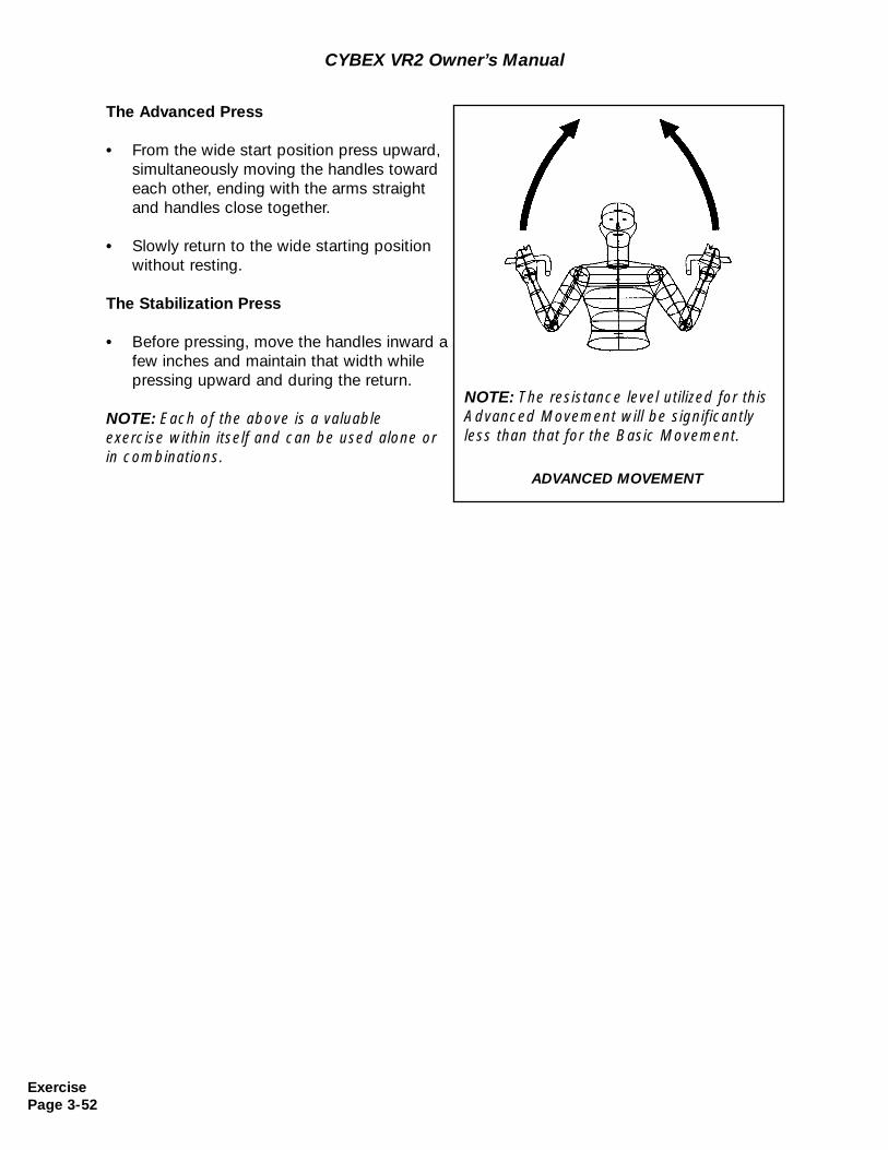
CYBEX VR2 Owner’s Manual
The Advanced Press
• From the wide start position press upward,simultaneously moving the handles towardeach other, ending with the arms straightand handles close together.
• Slowly return to the wide starting positionwithout resting.
The Stabilization Press
• Before pressing, move the handles inward afew inches and maintain that width while pressing upward and during the return.
NOTE: Each of the above is a valuable exercise within itself and can be used alone or in combinations.
ADVANCED MOVEMENT
NOTE: The resistance level utilized for thisAdvanced Movement will be significantlyless than that for the Basic Movement.
ExercisePage 3-52
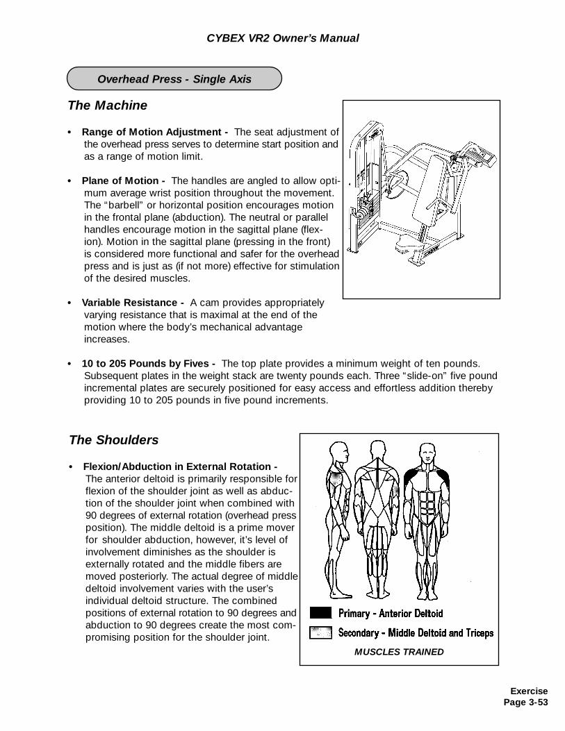
The Machine
• Range of Motion Adjustment - The seat adjustment ofthe overhead press serves to determine start position and as a range of motion limit.
• Plane of Motion - The handles are angled to allow opti-mum average wrist position throughout the movement.The “barbell” or horizontal position encourages motionin the frontal plane (abduction). The neutral or parallel handles encourage motion in the sagittal plane (flex-ion). Motion in the sagittal plane (pressing in the front)is considered more functional and safer for the overhead press and is just as (if not more) effective for stimulation of the desired muscles.
• Variable Resistance - A cam provides appropriately varying resistance that is maximal at the end of the motion where the body’s mechanical advantage increases.
• 10 to 205 Pounds by Fives - The top plate provides a minimum weight of ten pounds. Subsequent plates in the weight stack are twenty pounds each. Three “slide-on” five pound incremental plates are securely positioned for easy access and effortless addition thereby providing 10 to 205 pounds in five pound increments.
The Shoulders
• Flexion/Abduction in External Rotation - The anterior deltoid is primarily responsible for flexion of the shoulder joint as well as abduc-tion of the shoulder joint when combined with 90 degrees of external rotation (overhead press position). The middle deltoid is a prime mover for shoulder abduction, however, it’s level of involvement diminishes as the shoulder is externally rotated and the middle fibers are moved posteriorly. The actual degree of middle deltoid involvement varies with the user’s individual deltoid structure. The combined positions of external rotation to 90 degrees and abduction to 90 degrees create the most com-promising position for the shoulder joint.
MUSCLES TRAINED
ExercisePage 3-53
Overhead Press - Single Axis
CYBEX VR2 Owner’s Manual
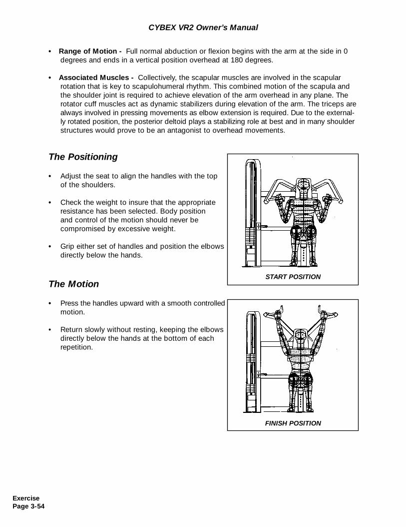
CYBEX VR2 Owner’s Manual
• Range of Motion - Full normal abduction or flexion begins with the arm at the side in 0 degrees and ends in a vertical position overhead at 180 degrees.
• Associated Muscles - Collectively, the scapular muscles are involved in the scapular rotation that is key to scapulohumeral rhythm. This combined motion of the scapula and the shoulder joint is required to achieve elevation of the arm overhead in any plane. Therotator cuff muscles act as dynamic stabilizers during elevation of the arm. The triceps are always involved in pressing movements as elbow extension is required. Due to the external-ly rotated position, the posterior deltoid plays a stabilizing role at best and in many shoulder structures would prove to be an antagonist to overhead movements.
The Positioning
• Adjust the seat to align the handles with the top of the shoulders.
• Check the weight to insure that the appropriate resistance has been selected. Body position and control of the motion should never be compromised by excessive weight.
• Grip either set of handles and position the elbows directly below the hands.
The Motion
• Press the handles upward with a smooth controlled motion.
• Return slowly without resting, keeping the elbows directly below the hands at the bottom of each repetition.
START POSITION
FINISH POSITION
ExercisePage 3-54
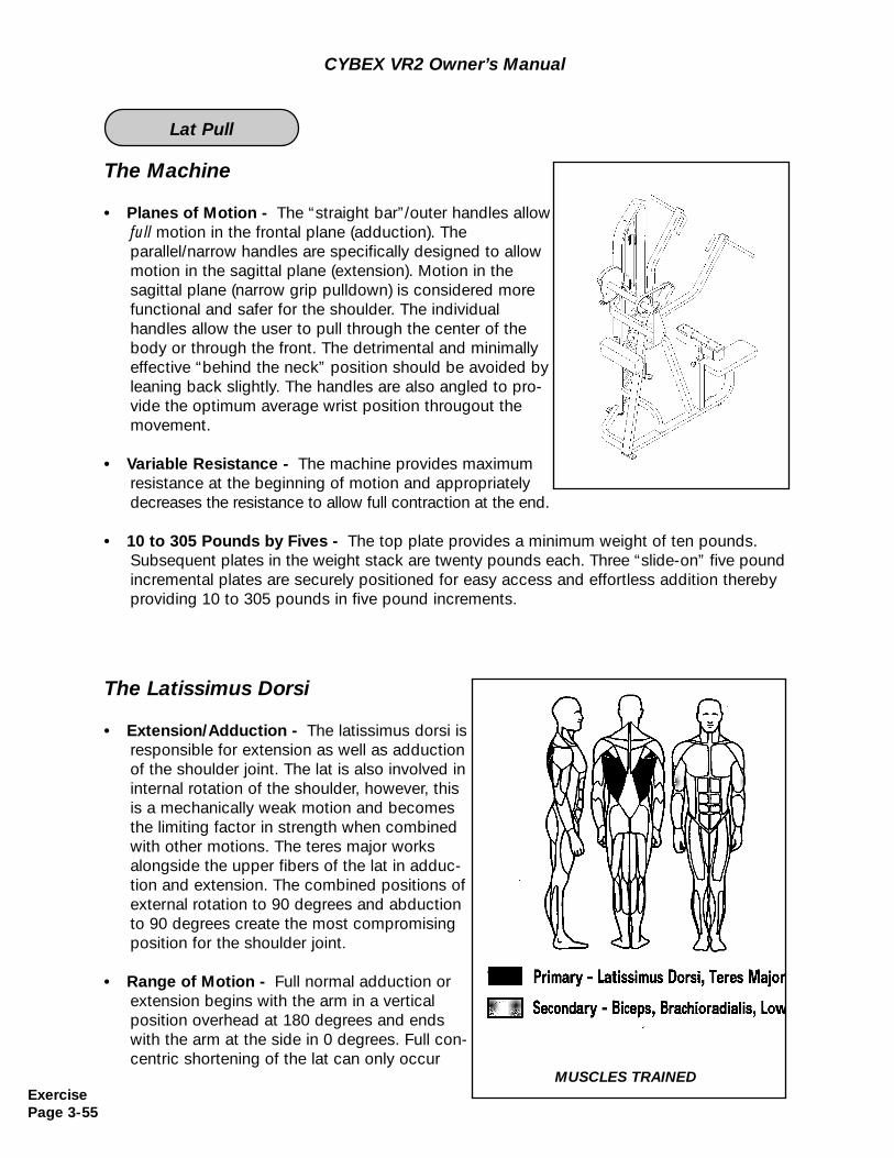
The Machine
• Planes of Motion - The “straight bar”/outer handles allow full motion in the frontal plane (adduction). The parallel/narrow handles are specifically designed to allow motion in the sagittal plane (extension). Motion in thesagittal plane (narrow grip pulldown) is considered morefunctional and safer for the shoulder. The individual handles allow the user to pull through the center of the body or through the front. The detrimental and minimally effective “behind the neck” position should be avoided byleaning back slightly. The handles are also angled to pro-vide the optimum average wrist position througout themovement.
• Variable Resistance - The machine provides maximum resistance at the beginning of motion and appropriately decreases the resistance to allow full contraction at the end.
• 10 to 305 Pounds by Fives - The top plate provides a minimum weight of ten pounds. Subsequent plates in the weight stack are twenty pounds each. Three “slide-on” five pound incremental plates are securely positioned for easy access and effortless addition thereby providing 10 to 305 pounds in five pound increments.
CYBEX VR2 Owner’s Manual
The Latissimus Dorsi
• Extension/Adduction - The latissimus dorsi is responsible for extension as well as adduction of the shoulder joint. The lat is also involved in internal rotation of the shoulder, however, this is a mechanically weak motion and becomes the limiting factor in strength when combined with other motions. The teres major works alongside the upper fibers of the lat in adduc-tion and extension. The combined positions of external rotation to 90 degrees and abductionto 90 degrees create the most compromising position for the shoulder joint.
• Range of Motion - Full normal adduction orextension begins with the arm in a vertical position overhead at 180 degrees and ends with the arm at the side in 0 degrees. Full con-centric shortening of the lat can only occur
MUSCLES TRAINEDExercisePage 3-55
Lat Pull
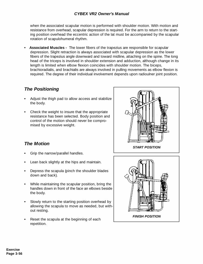
CYBEX VR2 Owner’s Manual
The Positioning
• Adjust the thigh pad to allow access and stabilize the body.
• Check the weight to insure that the appropriateresistance has been selected. Body position andcontrol of the motion should never be compro-mised by excessive weight.
when the associated scapular motion is performed with shoulder motion. With motion and resistance from overhead, scapular depression is required. For the arm to return to the start-ing position overhead the eccentric action of the lat must be accompanied by the scapular rotation of scapulohumeral rhythm.
• Associated Muscles - The lower fibers of the trapezius are responsible for scapular depression. Slight retraction is always associated with scapular depression as the lower fibers of the trapezius angle downward and toward midline, attaching on the spine. The longhead of the triceps is involved in shoulder extension and adduction, although change in its length is limited when elbow flexion coincides with shoulder motion. The biceps, brachioradialis, and brachialis are always involved in pulling movements as elbow flexion isrequired. The degree of their individual involvement depends upon radioulner joint position.
The Motion
• Grip the narrow/parallel handles.
• Lean back slightly at the hips and maintain.
• Depress the scapula (pinch the shoulder blades down and back).
• While maintaining the scapular position, bring the handles down in front of the face an elbows beside the body.
• Slowly return to the starting position overhead by allowing the scapula to move as needed, but with-out resting.
• Reset the scapula at the beginning of eachrepetition.
START POSITION
FINISH POSITION
ExercisePage 3-56
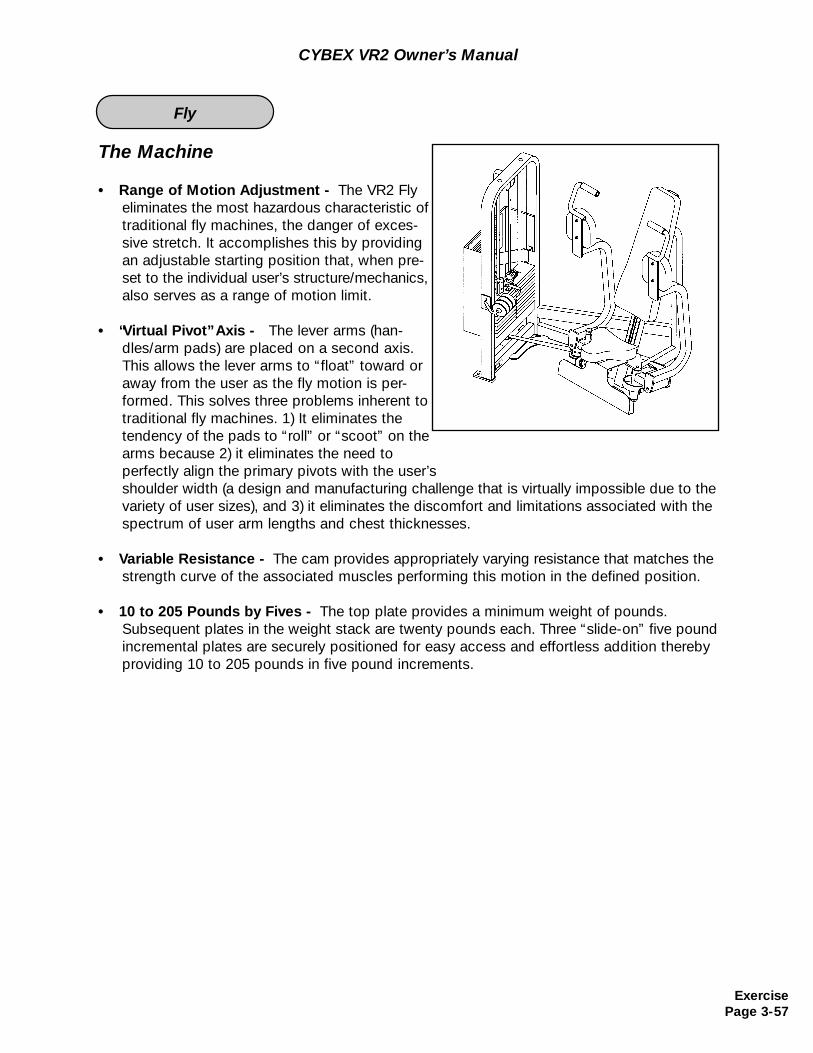
The Machine
• Range of Motion Adjustment - The VR2 Fly eliminates the most hazardous characteristic of traditional fly machines, the danger of exces-sive stretch. It accomplishes this by providingan adjustable starting position that, when pre-set to the individual user’s structure/mechanics, also serves as a range of motion limit.
• “Virtual Pivot” Axis - The lever arms (han-dles/arm pads) are placed on a second axis. This allows the lever arms to “float” toward or away from the user as the fly motion is per-formed. This solves three problems inherent to traditional fly machines. 1) It eliminates the tendency of the pads to “roll” or “scoot” on the arms because 2) it eliminates the need toperfectly align the primary pivots with the user’s shoulder width (a design and manufacturing challenge that is virtually impossible due to the variety of user sizes), and 3) it eliminates the discomfort and limitations associated with the spectrum of user arm lengths and chest thicknesses.
• Variable Resistance - The cam provides appropriately varying resistance that matches the strength curve of the associated muscles performing this motion in the defined position.
• 10 to 205 Pounds by Fives - The top plate provides a minimum weight of pounds. Subsequent plates in the weight stack are twenty pounds each. Three “slide-on” five pound incremental plates are securely positioned for easy access and effortless addition thereby providing 10 to 205 pounds in five pound increments.
CYBEX VR2 Owner’s Manual
ExercisePage 3-57
Fly
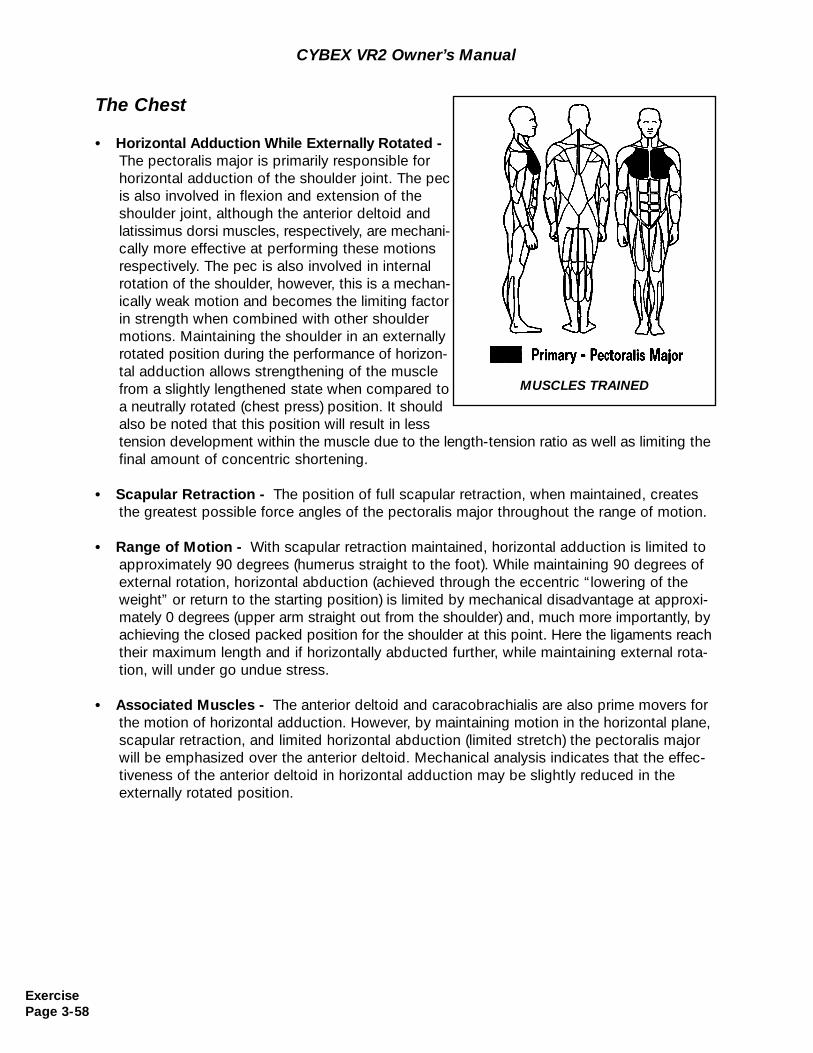
The Chest
• Horizontal Adduction While Externally Rotated -The pectoralis major is primarily responsible for horizontal adduction of the shoulder joint. The pecis also involved in flexion and extension of the shoulder joint, although the anterior deltoid and latissimus dorsi muscles, respectively, are mechani-cally more effective at performing these motions respectively. The pec is also involved in internal rotation of the shoulder, however, this is a mechan-ically weak motion and becomes the limiting factorin strength when combined with other shoulder motions. Maintaining the shoulder in an externally rotated position during the performance of horizon-tal adduction allows strengthening of the muscle from a slightly lengthened state when compared to a neutrally rotated (chest press) position. It should also be noted that this position will result in lesstension development within the muscle due to the length-tension ratio as well as limiting the final amount of concentric shortening.
• Scapular Retraction - The position of full scapular retraction, when maintained, creates the greatest possible force angles of the pectoralis major throughout the range of motion.
• Range of Motion - With scapular retraction maintained, horizontal adduction is limited to approximately 90 degrees (humerus straight to the foot). While maintaining 90 degrees of external rotation, horizontal abduction (achieved through the eccentric “lowering of the weight” or return to the starting position) is limited by mechanical disadvantage at approxi-mately 0 degrees (upper arm straight out from the shoulder) and, much more importantly, by achieving the closed packed position for the shoulder at this point. Here the ligaments reach their maximum length and if horizontally abducted further, while maintaining external rota-tion, will under go undue stress.
• Associated Muscles - The anterior deltoid and caracobrachialis are also prime movers for the motion of horizontal adduction. However, by maintaining motion in the horizontal plane, scapular retraction, and limited horizontal abduction (limited stretch) the pectoralis major will be emphasized over the anterior deltoid. Mechanical analysis indicates that the effec-tiveness of the anterior deltoid in horizontal adduction may be slightly reduced in the externally rotated position.
MUSCLES TRAINED
CYBEX VR2 Owner’s Manual
ExercisePage 3-58
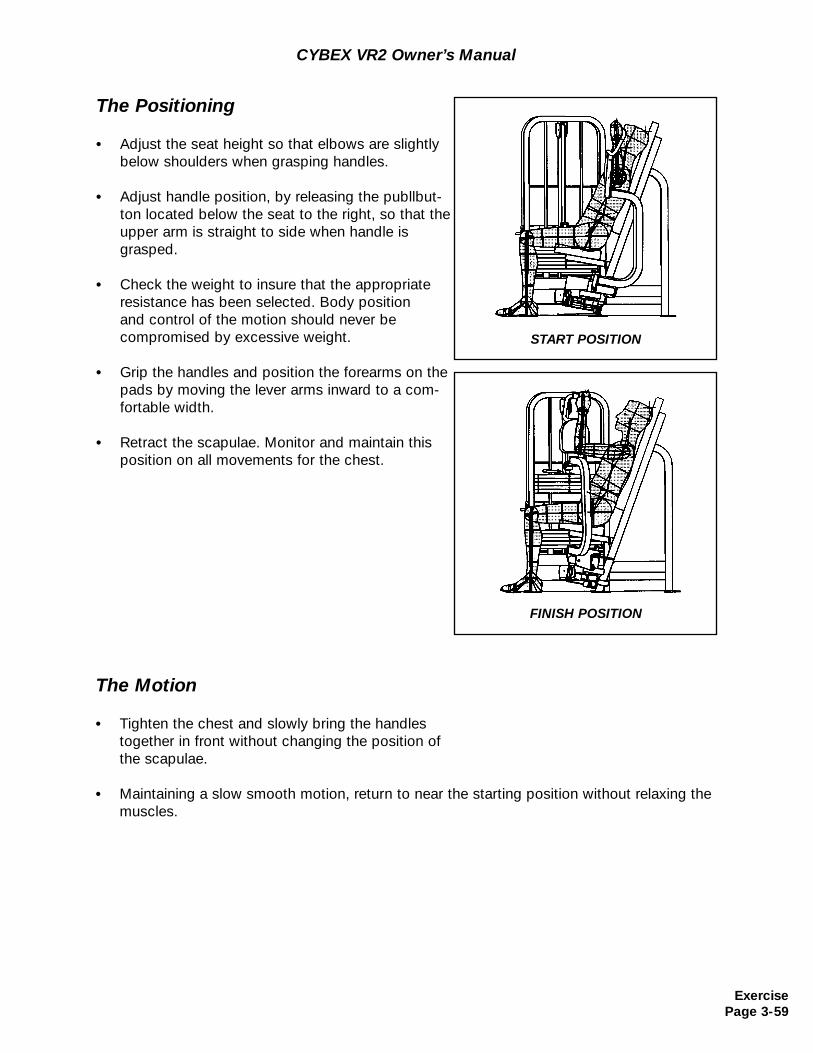
CYBEX VR2 Owner’s Manual
The Positioning
• Adjust the seat height so that elbows are slightly below shoulders when grasping handles.
• Adjust handle position, by releasing the publlbut-ton located below the seat to the right, so that theupper arm is straight to side when handle is grasped.
• Check the weight to insure that the appropriate resistance has been selected. Body position and control of the motion should never be compromised by excessive weight.
• Grip the handles and position the forearms on the pads by moving the lever arms inward to a com-fortable width.
• Retract the scapulae. Monitor and maintain this position on all movements for the chest.
The Motion
• Tighten the chest and slowly bring the handles together in front without changing the position of the scapulae.
• Maintaining a slow smooth motion, return to near the starting position without relaxing the muscles.
START POSITION
FINISH POSITION
ExercisePage 3-59
CYBEX VR2 Owner’s Manual
(This page intentionally left blank)
ExercisePage 3-60
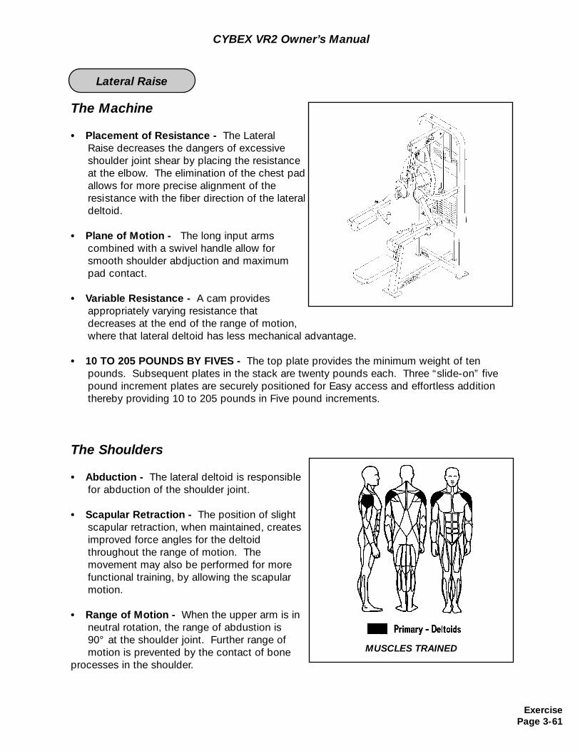
The Machine
• Placement of Resistance - The Lateral Raise decreases the dangers of excessive shoulder joint shear by placing the resistance at the elbow. The elimination of the chest padallows for more precise alignment of theresistance with the fiber direction of the lateraldeltoid.
• Plane of Motion - The long input arms combined with a swivel handle allow for smooth shoulder abdjuction and maximum pad contact.
• Variable Resistance - A cam provides appropriately varying resistance that decreases at the end of the range of motion, where that lateral deltoid has less mechanical advantage.
• 10 TO 205 POUNDS BY FIVES - The top plate provides the minimum weight of ten pounds. Subsequent plates in the stack are twenty pounds each. Three “slide-on” five pound increment plates are securely positioned for Easy access and effortless addition thereby providing 10 to 205 pounds in Five pound increments.
The Shoulders
• Abduction - The lateral deltoid is responsible for abduction of the shoulder joint.
• Scapular Retraction - The position of slight scapular retraction, when maintained, creates improved force angles for the deltoid throughout the range of motion. The movement may also be performed for more functional training, by allowing the scapular motion.
• Range of Motion - When the upper arm is in neutral rotation, the range of abdustion is 90° at the shoulder joint. Further range of motion is prevented by the contact of bone
processes in the shoulder.
CYBEX VR2 Owner’s Manual
ExercisePage 3-61
MUSCLES TRAINED
Lateral Raise
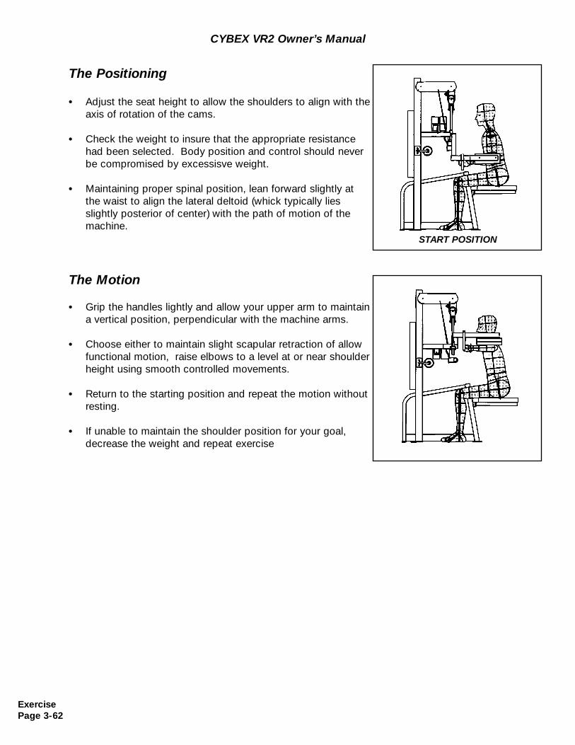
The Positioning
• Adjust the seat height to allow the shoulders to align with theaxis of rotation of the cams.
• Check the weight to insure that the appropriate resistance had been selected. Body position and control should never be compromised by excessisve weight.
• Maintaining proper spinal position, lean forward slightly at the waist to align the lateral deltoid (whick typically lies slightly posterior of center) with the path of motion of the machine.
ExercisePage 3-62
CYBEX VR2 Owner’s Manual
START POSITION
The Motion
• Grip the handles lightly and allow your upper arm to maintaina vertical position, perpendicular with the machine arms.
• Choose either to maintain slight scapular retraction of allow functional motion, raise elbows to a level at or near shoulderheight using smooth controlled movements.
• Return to the starting position and repeat the motion without resting.
• If unable to maintain the shoulder position for your goal, decrease the weight and repeat exercise
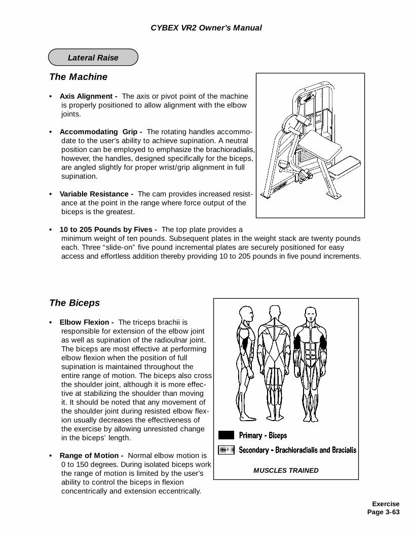
The Machine
• Axis Alignment - The axis or pivot point of the machine is properly positioned to allow alignment with the elbow joints.
• Accommodating Grip - The rotating handles accommo-date to the user’s ability to achieve supination. A neutral position can be employed to emphasize the brachioradialis, however, the handles, designed specifically for the biceps, are angled slightly for proper wrist/grip alignment in full supination.
• Variable Resistance - The cam provides increased resist-ance at the point in the range where force output of the biceps is the greatest.
• 10 to 205 Pounds by Fives - The top plate provides a minimum weight of ten pounds. Subsequent plates in the weight stack are twenty pounds each. Three “slide-on” five pound incremental plates are securely positioned for easy access and effortless addition thereby providing 10 to 205 pounds in five pound increments.
The Biceps
• Elbow Flexion - The triceps brachii is responsible for extension of the elbow jointas well as supination of the radioulnar joint.The biceps are most effective at performing elbow flexion when the position of full supination is maintained throughout the entire range of motion. The biceps also cross the shoulder joint, although it is more effec-tive at stabilizing the shoulder than moving it. It should be noted that any movement of the shoulder joint during resisted elbow flex-ion usually decreases the effectiveness of the exercise by allowing unresisted changein the biceps’ length.
• Range of Motion - Normal elbow motion is 0 to 150 degrees. During isolated biceps workthe range of motion is limited by the user’s ability to control the biceps in flexionconcentrically and extension eccentrically.
CYBEX VR2 Owner’s Manual
MUSCLES TRAINED
ExercisePage 3-63
Lateral Raise
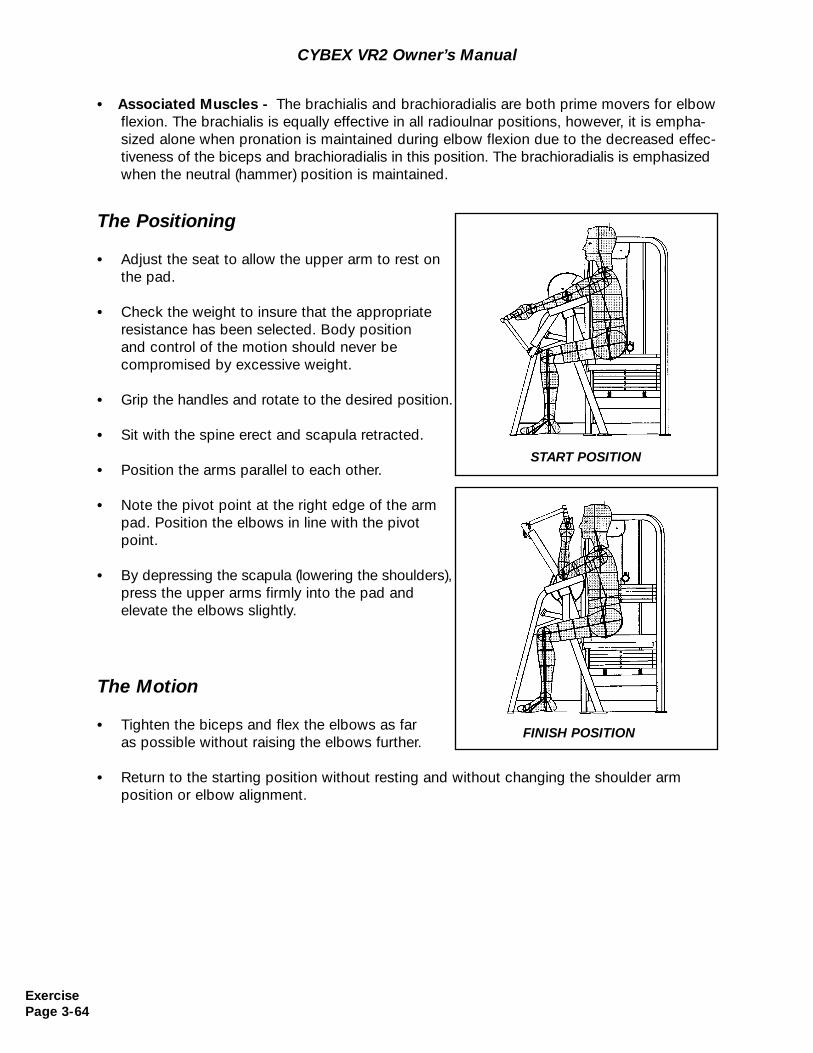
CYBEX VR2 Owner’s Manual
The Positioning
• Adjust the seat to allow the upper arm to rest on the pad.
• Check the weight to insure that the appropriate resistance has been selected. Body position and control of the motion should never be compromised by excessive weight.
• Grip the handles and rotate to the desired position.
• Sit with the spine erect and scapula retracted.
• Position the arms parallel to each other.
• Note the pivot point at the right edge of the arm pad. Position the elbows in line with the pivot point.
• By depressing the scapula (lowering the shoulders), press the upper arms firmly into the pad andelevate the elbows slightly.
The Motion
• Tighten the biceps and flex the elbows as far as possible without raising the elbows further.
• Return to the starting position without resting and without changing the shoulder arm position or elbow alignment.
START POSITION
FINISH POSITION
• Associated Muscles - The brachialis and brachioradialis are both prime movers for elbow flexion. The brachialis is equally effective in all radioulnar positions, however, it is empha-sized alone when pronation is maintained during elbow flexion due to the decreased effec-tiveness of the biceps and brachioradialis in this position. The brachioradialis is emphasized when the neutral (hammer) position is maintained.
ExercisePage 3-64
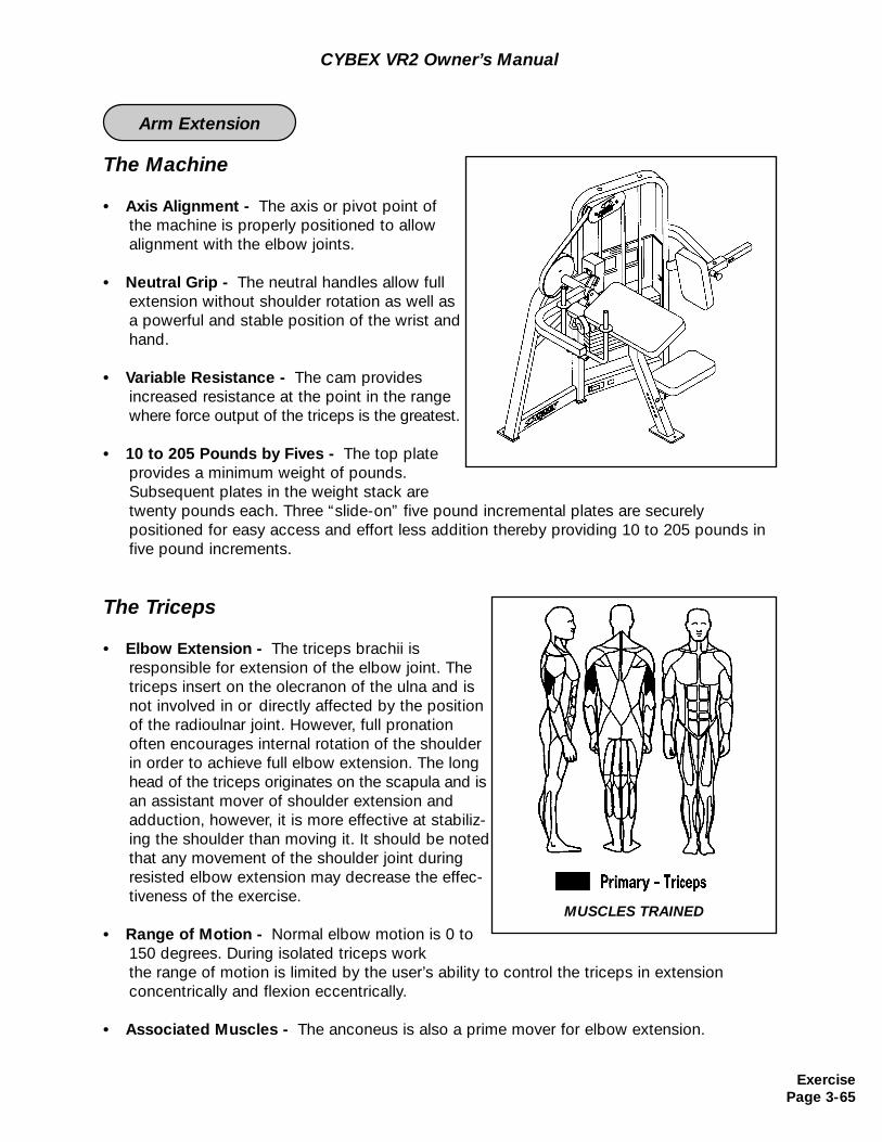
The Machine
• Axis Alignment - The axis or pivot point ofthe machine is properly positioned to allow alignment with the elbow joints.
• Neutral Grip - The neutral handles allow fullextension without shoulder rotation as well as a powerful and stable position of the wrist and hand.
• Variable Resistance - The cam provides increased resistance at the point in the range where force output of the triceps is the greatest.
• 10 to 205 Pounds by Fives - The top plateprovides a minimum weight of pounds. Subsequent plates in the weight stack are twenty pounds each. Three “slide-on” five pound incremental plates are securelypositioned for easy access and effort less addition thereby providing 10 to 205 pounds in five pound increments.
The Triceps
• Elbow Extension - The triceps brachii is responsible for extension of the elbow joint. The triceps insert on the olecranon of the ulna and isnot involved in or directly affected by the positionof the radioulnar joint. However, full pronation often encourages internal rotation of the shoulderin order to achieve full elbow extension. The long head of the triceps originates on the scapula and isan assistant mover of shoulder extension and adduction, however, it is more effective at stabiliz-ing the shoulder than moving it. It should be noted that any movement of the shoulder joint during resisted elbow extension may decrease the effec-tiveness of the exercise.
• Range of Motion - Normal elbow motion is 0 to 150 degrees. During isolated triceps work the range of motion is limited by the user’s ability to control the triceps in extension concentrically and flexion eccentrically.
• Associated Muscles - The anconeus is also a prime mover for elbow extension.
CYBEX VR2 Owner’s Manual
MUSCLES TRAINED
ExercisePage 3-65
Arm Extension
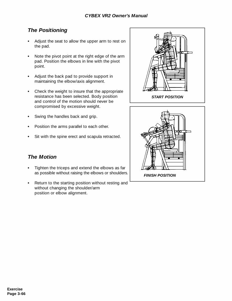
CYBEX VR2 Owner’s Manual
The Positioning
• Adjust the seat to allow the upper arm to rest on the pad.
• Note the pivot point at the right edge of the arm pad. Position the elbows in line with the pivot point.
• Adjust the back pad to provide support in maintaining the elbow/axis alignment.
• Check the weight to insure that the appropriate resistance has been selected. Body position and control of the motion should never be compromised by excessive weight.
• Swing the handles back and grip.
• Position the arms parallel to each other.
• Sit with the spine erect and scapula retracted.
The Motion
• Tighten the triceps and extend the elbows as far as possible without raising the elbows or shoulders.
• Return to the starting position without resting and without changing the shoulder/arm position or elbow alignment.
START POSITION
FINISH POSITION
ExercisePage 3-66
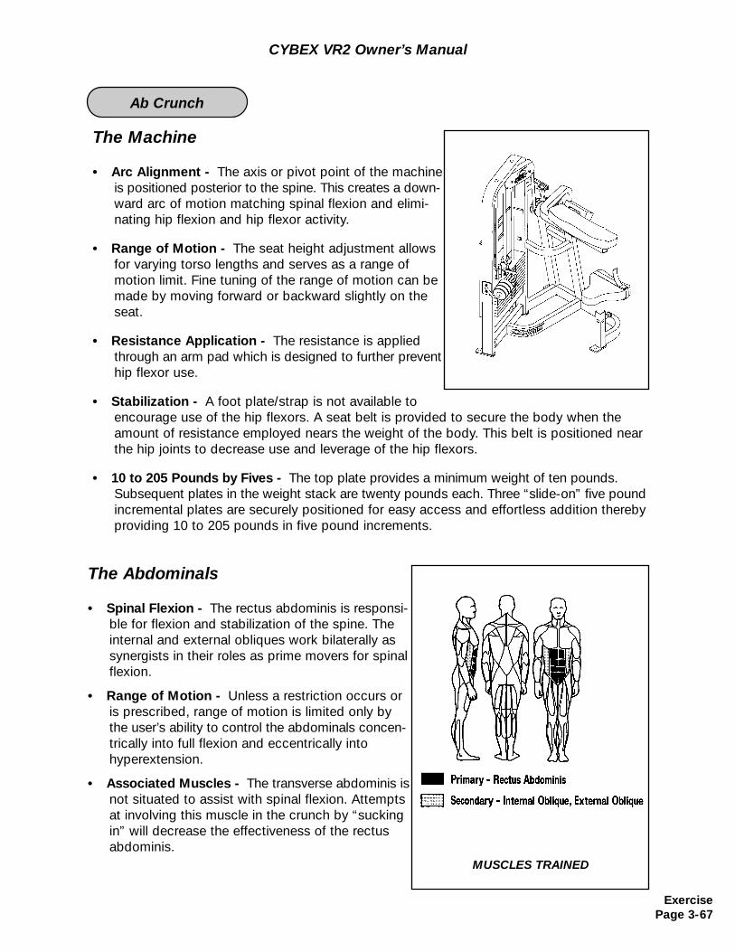
The Machine
• Arc Alignment - The axis or pivot point of the machineis positioned posterior to the spine. This creates a down-ward arc of motion matching spinal flexion and elimi-nating hip flexion and hip flexor activity.
• Range of Motion - The seat height adjustment allows for varying torso lengths and serves as a range of motion limit. Fine tuning of the range of motion can be made by moving forward or backward slightly on the seat.
• Resistance Application - The resistance is applied through an arm pad which is designed to further prevent hip flexor use.
• Stabilization - A foot plate/strap is not available to encourage use of the hip flexors. A seat belt is provided to secure the body when theamount of resistance employed nears the weight of the body. This belt is positioned near the hip joints to decrease use and leverage of the hip flexors.
• 10 to 205 Pounds by Fives - The top plate provides a minimum weight of ten pounds. Subsequent plates in the weight stack are twenty pounds each. Three “slide-on” five pound incremental plates are securely positioned for easy access and effortless addition thereby providing 10 to 205 pounds in five pound increments.
The Abdominals
• Spinal Flexion - The rectus abdominis is responsi-ble for flexion and stabilization of the spine. Theinternal and external obliques work bilaterally as synergists in their roles as prime movers for spinal flexion.
• Range of Motion - Unless a restriction occurs oris prescribed, range of motion is limited only by the user’s ability to control the abdominals concen-trically into full flexion and eccentrically into hyperextension.
• Associated Muscles - The transverse abdominis isnot situated to assist with spinal flexion. Attempts at involving this muscle in the crunch by “sucking in” will decrease the effectiveness of the rectus abdominis.
CYBEX VR2 Owner’s Manual
MUSCLES TRAINED
ExercisePage 3-67
Ab Crunch

The Positioning
• Adjust the seat to align the arm pad with the top of theshoulders/base of the neck. Raise the seat to decrease range of motion. Lower the seat to increase range of motion.
• Check the weight to insure that the apprpriate resistance has been selected. Body position and control of the motion should never be compromised byexcessive weight.
• Position the feet flat on the floor and use the seat belt if needed.
• Cross the arms over the pad and sit erect with thechest near the edge of the pad.
CYBEX VR2 Owner’s Manual
ExercisePage 3-68
START POSITION
The Motion
• Tighten the abdominals and crunch smoothly as far as possible. Stabilize the shoulders and lead with the ribs.
• Slowly return to the starting position without resting.
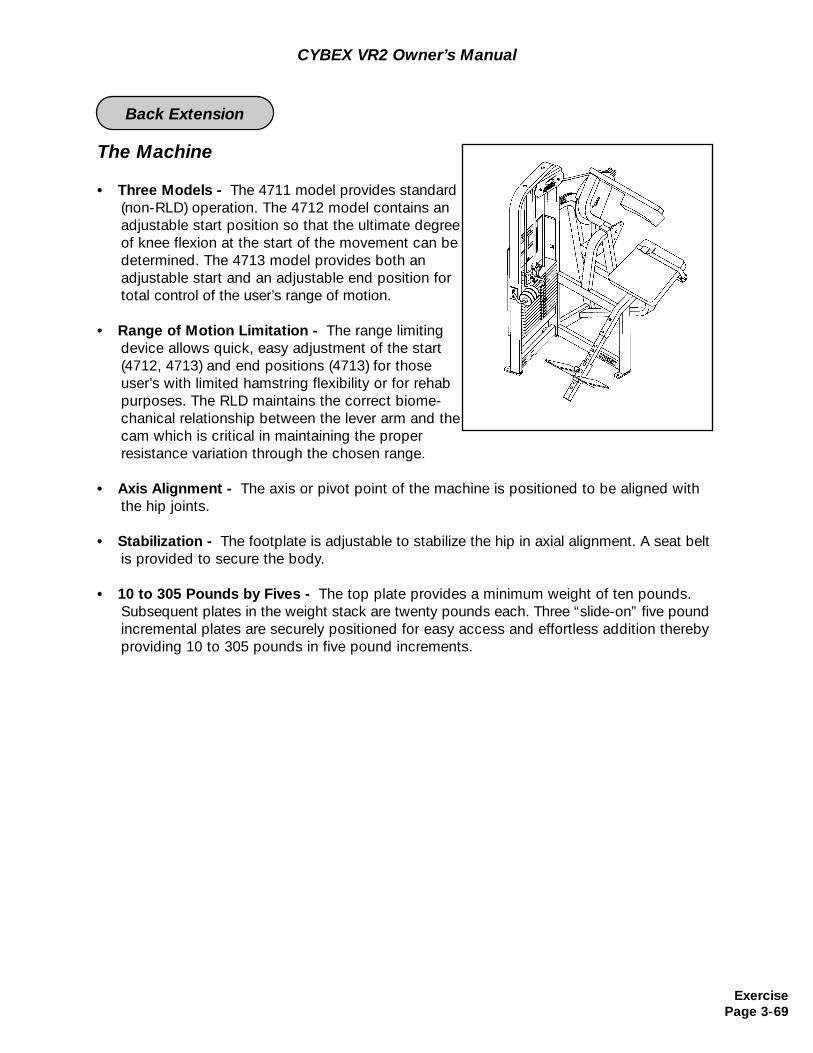
The Machine
• Three Models - The 4711 model provides standard (non-RLD) operation. The 4712 model contains an adjustable start position so that the ultimate degree of knee flexion at the start of the movement can be determined. The 4713 model provides both an adjustable start and an adjustable end position for total control of the user’s range of motion.
• Range of Motion Limitation - The range limiting device allows quick, easy adjustment of the start (4712, 4713) and end positions (4713) for those user’s with limited hamstring flexibility or for rehab purposes. The RLD maintains the correct biome-chanical relationship between the lever arm and the cam which is critical in maintaining the proper resistance variation through the chosen range.
• Axis Alignment - The axis or pivot point of the machine is positioned to be aligned with the hip joints.
• Stabilization - The footplate is adjustable to stabilize the hip in axial alignment. A seat beltis provided to secure the body.
• 10 to 305 Pounds by Fives - The top plate provides a minimum weight of ten pounds. Subsequent plates in the weight stack are twenty pounds each. Three “slide-on” five poundincremental plates are securely positioned for easy access and effortless addition thereby providing 10 to 305 pounds in five pound increments.
CYBEX VR2 Owner’s Manual
ExercisePage 3-69
Back Extension
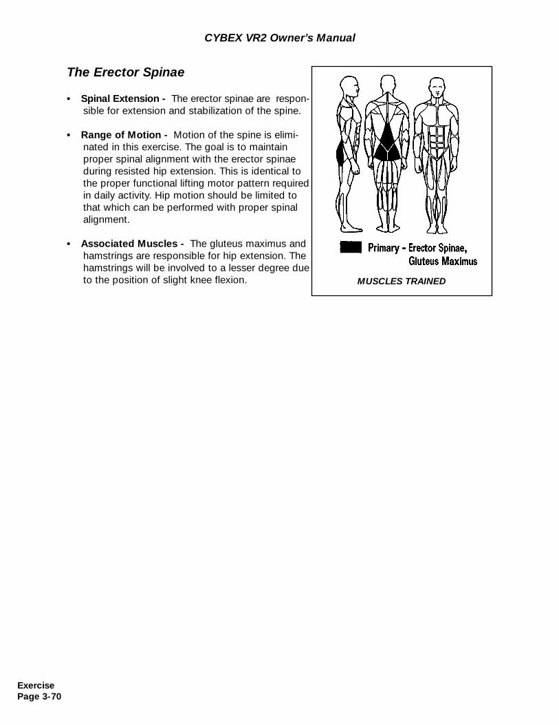
CYBEX VR2 Owner’s Manual
The Erector Spinae
• Spinal Extension - The erector spinae are respon-sible for extension and stabilization of the spine.
• Range of Motion - Motion of the spine is elimi-nated in this exercise. The goal is to maintain proper spinal alignment with the erector spinae during resisted hip extension. This is identical to the proper functional lifting motor pattern required in daily activity. Hip motion should be limited to that which can be performed with proper spinalalignment.
• Associated Muscles - The gluteus maximus and hamstrings are responsible for hip extension. The hamstrings will be involved to a lesser degree due to the position of slight knee flexion. MUSCLES TRAINED
ExercisePage 3-70
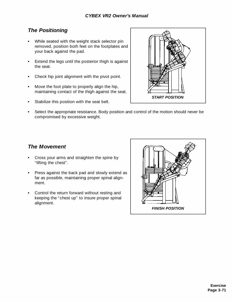
CYBEX VR2 Owner’s Manual
The Positioning
• While seated with the weight stack selector pinremoved, position both feet on the footplates and your back against the pad.
• Extend the legs until the posterior thigh is against the seat.
• Check hip joint alignment with the pivot point.
• Move the foot plate to properly align the hip,maintaining contact of the thigh against the seat.
• Stabilize this position with the seat belt.
• Select the appropriate resistance. Body position and control of the motion should never be compromised by excessive weight.
The Movement
• Cross your arms and straighten the spine by“lifting the chest”.
• Press against the back pad and slowly extend as far as possible, maintaining proper spinal align-ment.
• Control the return forward without resting and keeping the “chest up” to insure proper spinal alignment.
START POSITION
FINISH POSITION
ExercisePage 3-71
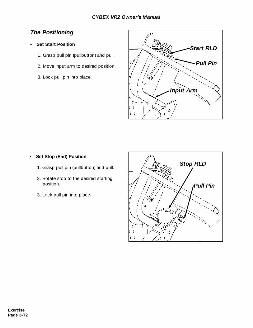
CYBEX VR2 Owner’s Manual
The Positioning
• Set Start Position
1. Grasp pull pin (pullbutton) and pull.
2. Move input arm to desired position.
3. Lock pull pin into place.
• Set Stop (End) Position
1. Grasp pull pin (pullbutton) and pull.
2. Rotate stop to the desired starting position.
3. Lock pull pin into place.
Start RLD
Pull Pin
Stop RLD
Pull Pin
Input Arm
ExercisePage 3-72
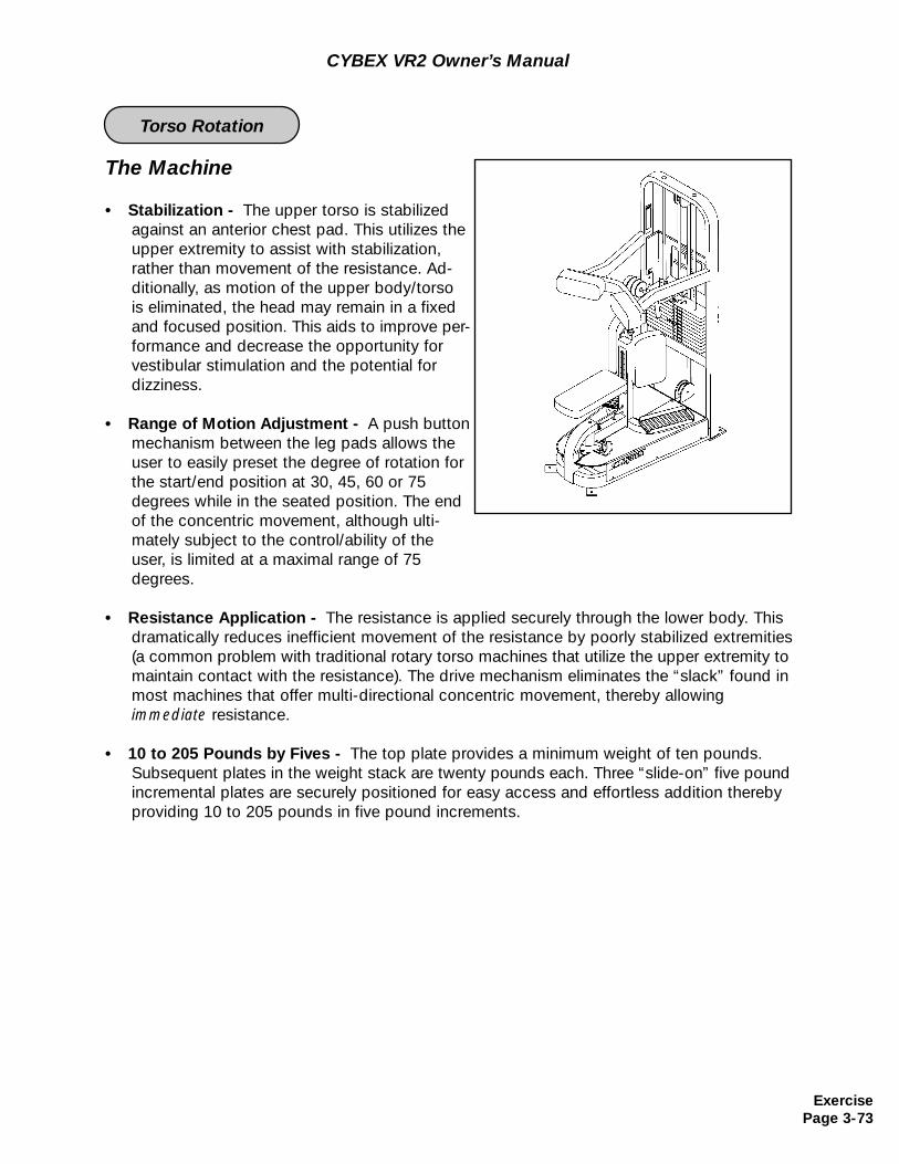
The Machine
• Stabilization - The upper torso is stabilized against an anterior chest pad. This utilizes the upper extremity to assist with stabilization, rather than movement of the resistance. Ad- ditionally, as motion of the upper body/torso is eliminated, the head may remain in a fixed and focused position. This aids to improve per-formance and decrease the opportunity for vestibular stimulation and the potential for dizziness.
• Range of Motion Adjustment - A push buttonmechanism between the leg pads allows the user to easily preset the degree of rotation for the start/end position at 30, 45, 60 or 75 degrees while in the seated position. The end of the concentric movement, although ulti-mately subject to the control/ability of the user, is limited at a maximal range of 75 degrees.
• Resistance Application - The resistance is applied securely through the lower body. Thisdramatically reduces inefficient movement of the resistance by poorly stabilized extremities (a common problem with traditional rotary torso machines that utilize the upper extremity to maintain contact with the resistance). The drive mechanism eliminates the “slack” found in most machines that offer multi-directional concentric movement, thereby allowing immediate resistance.
• 10 to 205 Pounds by Fives - The top plate provides a minimum weight of ten pounds. Subsequent plates in the weight stack are twenty pounds each. Three “slide-on” five pound incremental plates are securely positioned for easy access and effortless addition thereby providing 10 to 205 pounds in five pound increments.
CYBEX VR2 Owner’s Manual
ExercisePage 3-73
Torso Rotation
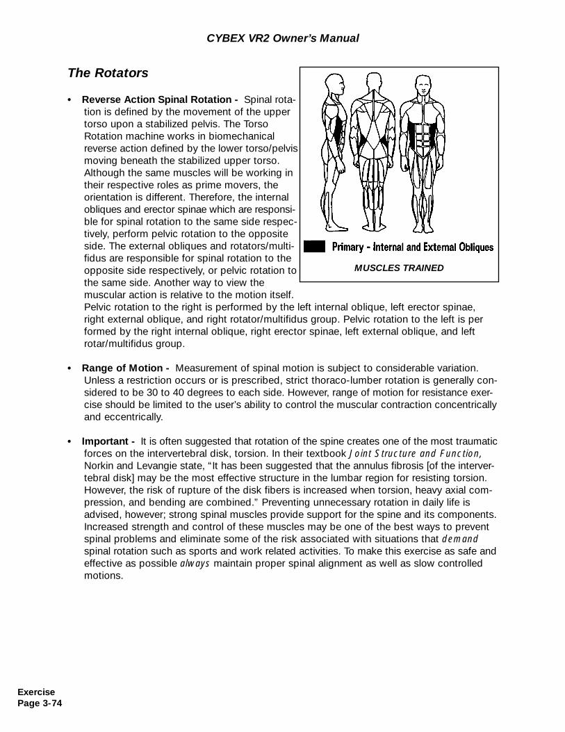
The Rotators
• Reverse Action Spinal Rotation - Spinal rota-tion is defined by the movement of the upper torso upon a stabilized pelvis. The Torso Rotation machine works in biomechanical reverse action defined by the lower torso/pelvis moving beneath the stabilized upper torso. Although the same muscles will be working in their respective roles as prime movers, the orientation is different. Therefore, the internal obliques and erector spinae which are responsi-ble for spinal rotation to the same side respec-tively, perform pelvic rotation to the opposite side. The external obliques and rotators/multi-fidus are responsible for spinal rotation to the opposite side respectively, or pelvic rotation to the same side. Another way to view themuscular action is relative to the motion itself. Pelvic rotation to the right is performed by the left internal oblique, left erector spinae, right external oblique, and right rotator/multifidus group. Pelvic rotation to the left is performed by the right internal oblique, right erector spinae, left external oblique, and left rotar/multifidus group.
• Range of Motion - Measurement of spinal motion is subject to considerable variation. Unless a restriction occurs or is prescribed, strict thoraco-lumber rotation is generally con-sidered to be 30 to 40 degrees to each side. However, range of motion for resistance exer-cise should be limited to the user’s ability to control the muscular contraction concentrically and eccentrically.
• Important - It is often suggested that rotation of the spine creates one of the most traumaticforces on the intervertebral disk, torsion. In their textbook Joint Structure and Function, Norkin and Levangie state, “It has been suggested that the annulus fibrosis [of the interver-tebral disk] may be the most effective structure in the lumbar region for resisting torsion. However, the risk of rupture of the disk fibers is increased when torsion, heavy axial com-pression, and bending are combined.” Preventing unnecessary rotation in daily life isadvised, however; strong spinal muscles provide support for the spine and its components. Increased strength and control of these muscles may be one of the best ways to prevent spinal problems and eliminate some of the risk associated with situations that demandspinal rotation such as sports and work related activities. To make this exercise as safe and effective as possible always maintain proper spinal alignment as well as slow controlledmotions.
MUSCLES TRAINED
CYBEX VR2 Owner’s Manual
ExercisePage 3-74
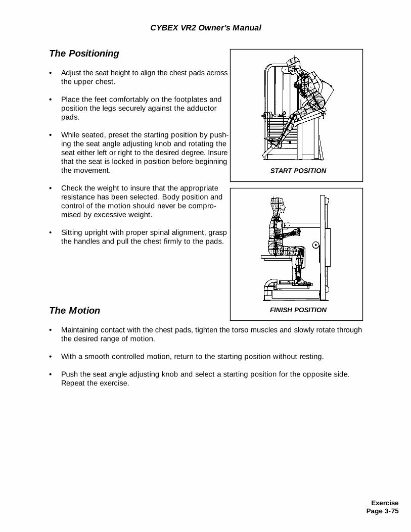
CYBEX VR2 Owner’s Manual
The Positioning
• Adjust the seat height to align the chest pads across the upper chest.
• Place the feet comfortably on the footplates and position the legs securely against the adductor pads.
• While seated, preset the starting position by push-ing the seat angle adjusting knob and rotating the seat either left or right to the desired degree. Insure that the seat is locked in position before beginning the movement.
• Check the weight to insure that the appropriate resistance has been selected. Body position and control of the motion should never be compro-mised by excessive weight.
• Sitting upright with proper spinal alignment, grasp the handles and pull the chest firmly to the pads.
The Motion
• Maintaining contact with the chest pads, tighten the torso muscles and slowly rotate through the desired range of motion.
• With a smooth controlled motion, return to the starting position without resting.
• Push the seat angle adjusting knob and select a starting position for the opposite side. Repeat the exercise.
START POSITION
FINISH POSITION
ExercisePage 3-75
CYBEX VR2 Owner’s Manual
ExercisePage 3-76
This page intentionally left blank
Chapter 4 - Customer Service
CustomerService
Page 4-1
Contacting Service
Hours of phone service are Monday through Friday from 8:00 a.m. to 6:00 p.m. EasternStandard Time.
For Cybex customers living in the USA, contact Cybex Customer Service at 800-766-3211.
For Cybex customers living outside the USA, contact Cybex Customer Service at 508-533-4300 or fax 508-533-5183.
Order parts and find information on the web at www.cybexinternational.com or by e-mail [email protected].
Ordering Parts
Visit cybexinternational.com to shop for parts online or fax your order to 508-533-5183. Tospeak with a customer service representative, call 800-766-3211 (for customers living withinthe USA) or 508-533-4300 (for customers outside the USA). You may also contact us throughemail at [email protected]
Having the following information ready when calling will assist our Cybex representatives inserving you:
• Unit Serial Number• Product Name
The unit serial number and product name can be found on the serial number decal. SeeChapter 8 for exact location of serial number decal.
• Part Description• Part Number
Part descriptions and part numbers are located in Chapter 8 of this manual.
CustomerServicePage 4-2
CYBEX VR2 Owner’s Manual
The Return Material Authorization (RMA) system outlines the procedures to follow whenreturning material for placement, repair, or credit. The system assures that returned materialsare properly handled and analyzed. Follow the following procedures carefully.
Contact your authorized Cybex dealer on all warranty-related matters. Your local Cybex dealer will request a RMA from Cybex, if applicable. Under no circumstances will defectiveparts or equipment be accepted by Cybex without proper RMA and an Automated ReturnService (ARS) label.
1. Call the Customer Service Hotline listed above for the return of any time that is defective.
2. Provide the technician with a detailed description of the problem you are having or the defect in the item you wish to return.
3. Provide the model and serial number of your Eagle equipment
4. At Cybex’s discretion, the technician may request that you return the problem part(s) to Cybex for evaluation and repair or replacement. The technical will assign you a RMA number and will send you an ARS label. The ARS label and the RMA numbers must be clearly displayed on the outside of the package that contains theitem(s) to be returned. Include the description of the problem, the serial number of the Eagle equipment and the name and address of the owner in the package alongwith the part(s).
5. Forward the package through UPS to Cybex.Attn: Customer Service DepartmentCybex International, inc.,10 Trotter DriveMedway, MA 02053
NOTE: Merchandise returned without an RMA number on the outside of the package or shipments sent C.O.D. will not be accepted by the Cybex receiving department.
Return Material Authorization (RMA)
• Shipping Address• Contact Name
In addition to your shipping address and contact name, your account number is helpful but not required.
CustomerService
Page 4-3
CYBEX VR2 Owner’s Manual
Materials damaged in shipment should not be returned for credit. Shipping damages are theresponsibility of the carrier (UPS, Federal Express, trucking companies, etc.)
Apparent Damage - Upon receipt of your shipment, check all items carefully. Any damageseen with a visual check must be noted on the freight bill and signed by the carriers agent.Failure to do so will result in the carriers refusal to honor your damage claim. The carrier willprovide you with the required forms for filing such claims.
Concealed Damage - Damage not seen with a visual check upon receipt of a shipment butnotices later must be reported to the carrier as soon as possible. Upon discovery of thedamage, a written or phone request to the carrier asking them to perform an inspection of thematerials must be made within ten days of the delivery date. Keep all shipping containers andpacking materials as they will be needed in the inspection process. The carrier will provideyou with and inspection report and the necessary forms for filing a concealed damage claim.Concealed damage claim is the carriers responsibility.
Damaged Parts
CustomerServicePage 4-4
CYBEX VR2 Owner’s Manual
This page intentionally left blank
We would like to take this opportunity to thank you for your purchase of CYBEX StrengthSystems and to assure you that our commitment to excellence includes a dedication to customer service.
Freight and inside delivery charges cover trucking and handling costs necessary to place yourequipment in any pre-determined location in your facility. This does not include unusual orspecial circumstances. If you purchased installation, your equipment will be assembled foryou.
A thorough inspection of our CYBEX Strength Systems ensures that the equipment leaves ourfacility in flawless condition. Although unlikely, minor damage may occur in transmit from ourplant to your facility. Therefore, to guarantee that any damage is covered and then corrected,we ask that you follow the procedure below upon delivery to help ensure your satisfaction.
Upon arrival, it is important that you thoroughly inspect all of the equipment for damage.
If you discover damage, point it out to the truck driver and request that the driver make arecord of the damage on the receiving report. Be sure to obtain a copy of the receiving reportfor your files.
• Contact CYBEX Technical Support if you received damaged equipment and provide them with the information on the report regarding your damaged equipment.
• Contact CYBEX Inside Sales if you did not receive the appropriate equipment and provide them with the information regarding your order.
You may call CYBEX at 1-888-462-9239 (1-888-GO CYBEX) and specify if you are calling fora Technical Support Representative or an Inside Sales Representative.
Delivery& Installation
Page 5-1
Delivery Inspection
Chapter 5 - Delivery & Installation
Allow the appropriate operating space between machines. It is the responsibility of the purchaser to determine the appropriate operating space for customer safety and convenience. Do not crowd the exercise area.
Installation
Delivery& InstallationPage 5-2
Cybex VR2 Owner’s Manual
Anchoring
Anchoring machines provide maximum stability.
Securely anchor each piece of Strength Systems equipment to the floor using theanchor holes provided with each machine.
NOTE: CYBEX is not responsible for the actual anchoring of equipment. Consult with a professional contractor.
Use fasteners having a minimum of 500 lbs. tensile capacity (3/8” grade 2 bolts or better).
If all legs/frames do not contact surface, DO NOT pull down with anchors. Shim any leg orframe not in contact with surface with flat washers.
Safety
Use extra caution when assembling and installing equipment, particularly when lifting or moving heavy objects (such as installing weight stacks) and when using power tools.
Before using any machine, read and understand the following material:
• Warning and caution labels• Chapter 2 - General Exercise Guidelines• Chapter 3 - Exercises• Chapter 6 - Maintenance
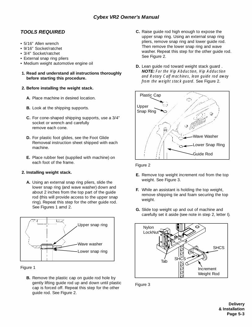
Delivery& Installation
Page 5-3
Cybex VR2 Owner’s Manual
TOOLS REQUIRED
• 5/16” Allen wrench• 9/16” Socket/ratchet• 3/4” Socket/ratchet• External snap ring pliers• Medium weight automotive engine oil
1. Read and understand all instructions thoroughly before starting this procedure.
2. Before installing the weight stack.
A. Place machine in desired location.
B. Look at the shipping supports.
C. For cone-shaped shipping supports, use a 3/4” socket or wrench and carefully remove each cone.
D. For plastic foot glides, see the Foot GlideRemoveal instruction sheet shipped with each machine.
E. Place rubber feet (supplied with machine) on each foot of the frame.
2. Installing weight stack.
A. Using an external snap ring pliers, slide the lower snap ring (and wave washer) down and about 2 inches from the top part of the guide rod (this will provide access to the upper snap ring). Repeat this step for the other guide rod. See Figures 1 amd 2.
B. Remove the plastic cap on guide rod hole by gently lifting guide rod up and down until plastic cap is forced off. Repeat this step for the other guide rod. See Figure 2.
E. Remove top weight increment rod from the top weight. See Figure 3.
F. While an assistant is holding the top weight, remove shipping tie and foam securing the top weight.
G. Slide top weight up and out of machine and carefully set it aside (see note in step 2, letter I).
Figure 1
C. Raise guide rod high enough to expose the upper snap ring. Using an external snap ring pliers, remove snap ring and lower guide rod. Then remove the lower snap ring and wave washer. Repeat this step for the other guide rod. See Figure 2.
D. Lean guide rod toward weight stack guard .NOTE: For the Hip Abduction, Hip Adduction and Rotary Calf machines, lean guide rod away from the weight stack guard. See Figure 2.
Figure 3
Figure 2
Upper snap ring
Wave washer
Lower snap ring
Plastic Cap
UpperSnap Ring
Guide Rod
Wave Washer
Lower Snap Ring
Increment Weight Rod
SHCS
SHCS
NylonLockNut
Tab
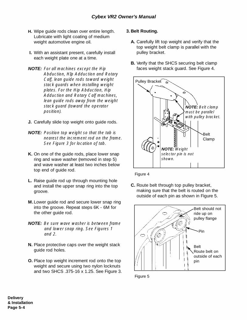
Delivery& InstallationPage 5-4
Cybex VR2 Owner’s Manual
H. Wipe guide rods clean over entire length.Lubricate with light coating of mediumweight automotive engine oil.
I. With an assistant present, carefully install each weight plate one at a time.
NOTE: For all machines except the Hip Abduction, HIp Adduction and Rotary Calf, lean guide rods toward weightstack guards when installing weightplates. For the Hip Abduction, Hip Adduction and Rotary Calf machines,lean guide rods away from the weight stack guard (toward the operatorposition).
J. Carefully slide top weight onto guide rods.
NOTE: Position top weight so that the tab isnearest the increment rod on the frame. See Figure 3 for location of tab.
K. On one of the guide rods, place lower snapring and wave washer (removed in step 5) and wave washer at least two inches below top end of guide rod.
L. Raise guide rod up through mounting holeand install the upper snap ring into the top groove.
M.Lower guide rod and secure lower snap ringinto the groove. Repeat steps 6K - 6M for the other guide rod.
NOTE: Be sure wave washer is between frame and lower snap ring. See Figures 1 and 2.
N. Place protective caps over the weight stack guide rod holes.
O. Place top weight increment rod onto the topweight and secure using two nylon locknuts and two SHCS .375-16 x 1.25. See Figure 3.
3. Belt Routing.
A. Carefully lift top weight and verify that the top weight belt clamp is parallel with the pulley bracket.
B. Verify that the SHCS securing belt clampfaces weight stack guard. See Figure 4.
Figure 4
C. Route belt through top pulley bracket, making sure that the belt is routed on the outside of each pin as shown in Figure 5.
Figure 5
Belt should notride up on pulley flange
Pin
BeltRoute belt onoutside of eachpin
NOTE: Belt clampmust be parallelwith pulley bracket.
Pulley Bracket
BeltClamp
NOTE: Weightselector pin is notshown.
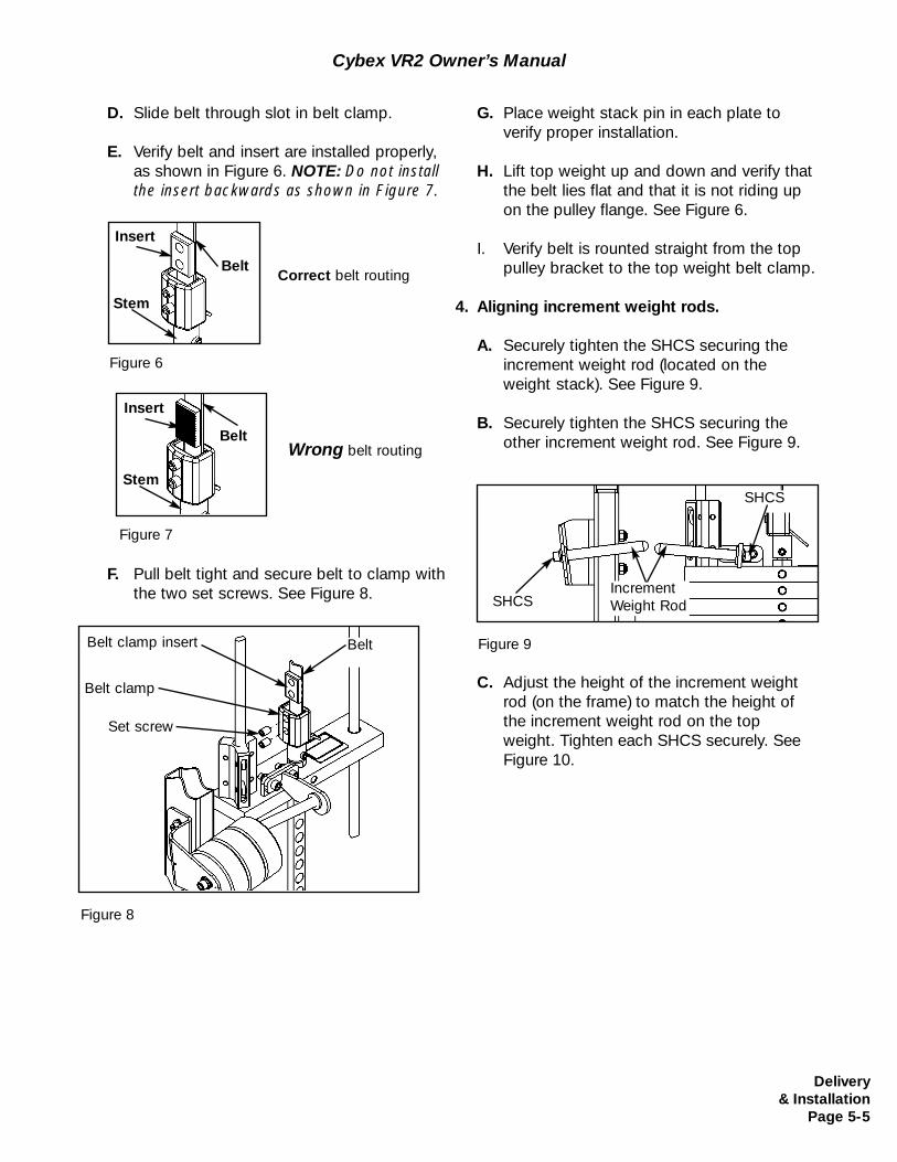
Delivery& Installation
Page 5-5
Cybex VR2 Owner’s Manual
D. Slide belt through slot in belt clamp.
E. Verify belt and insert are installed properly, as shown in Figure 6. NOTE: Do not install the insert backwards as shown in Figure 7.
F. Pull belt tight and secure belt to clamp with the two set screws. See Figure 8.
Figure 8
G. Place weight stack pin in each plate to verify proper installation.
H. Lift top weight up and down and verify that the belt lies flat and that it is not riding up on the pulley flange. See Figure 6.
I. Verify belt is rounted straight from the top pulley bracket to the top weight belt clamp.
4. Aligning increment weight rods.
A. Securely tighten the SHCS securing theincrement weight rod (located on theweight stack). See Figure 9.
B. Securely tighten the SHCS securing the other increment weight rod. See Figure 9.
Figure 9
SHCS
SHCS
Increment Weight Rod
Correct belt routing
Wrong belt routing
Figure 6
Figure 7
Stem
Belt
Insert
Stem
Belt
Insert
C. Adjust the height of the increment weight rod (on the frame) to match the height of the increment weight rod on the top weight. Tighten each SHCS securely. See Figure 10.
Belt clamp
BeltBelt clamp insert
Set screw
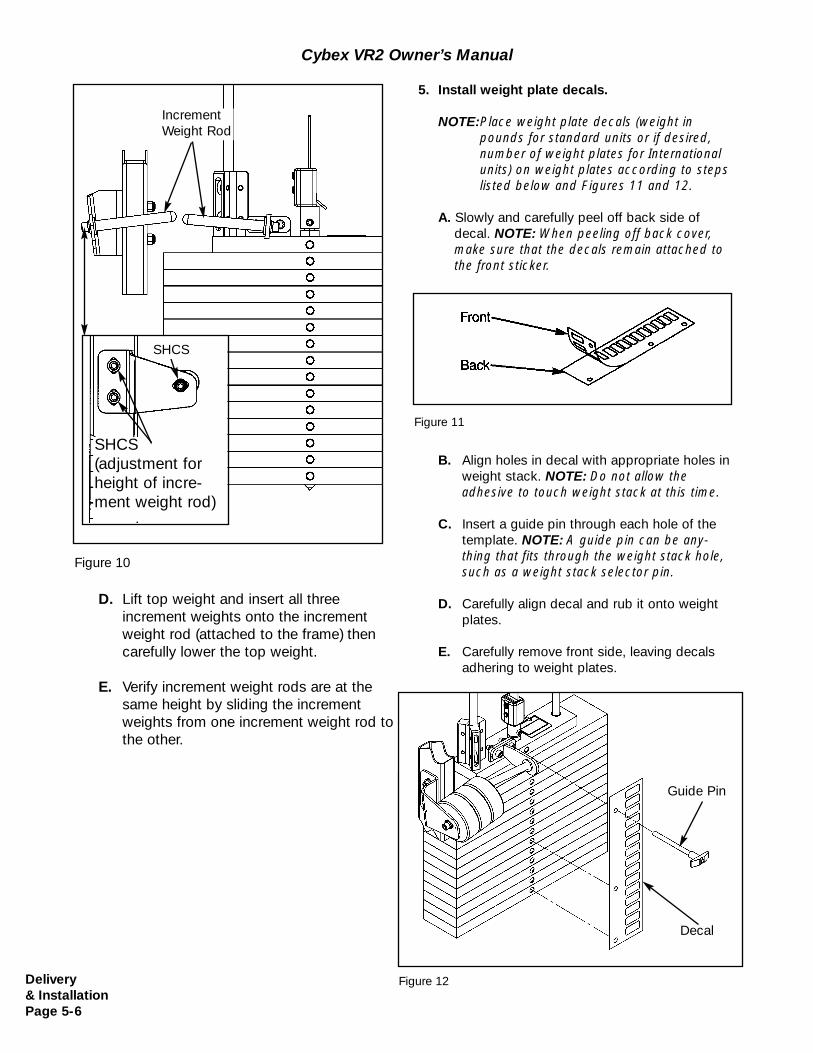
Delivery& InstallationPage 5-6
Cybex VR2 Owner’s Manual
5. Install weight plate decals.
NOTE:Place weight plate decals (weight inpounds for standard units or if desired, number of weight plates for Internationalunits) on weight plates according to stepslisted below and Figures 11 and 12.
A. Slowly and carefully peel off back side of decal. NOTE: When peeling off back cover, make sure that the decals remain attached to the front sticker.
B. Align holes in decal with appropriate holes in weight stack. NOTE: Do not allow the adhesive to touch weight stack at this time.
C. Insert a guide pin through each hole of the template. NOTE: A guide pin can be any-thing that fits through the weight stack hole, such as a weight stack selector pin.
D. Carefully align decal and rub it onto weight plates.
E. Carefully remove front side, leaving decals adhering to weight plates.
Figure 11
Figure 12
Figure 10
D. Lift top weight and insert all three increment weights onto the incrementweight rod (attached to the frame) then carefully lower the top weight.
E. Verify increment weight rods are at thesame height by sliding the increment weights from one increment weight rod to the other.
SHCS (adjustment forheight of incre-ment weight rod)
SHCS
Guide Pin
Decal
Increment Weight Rod
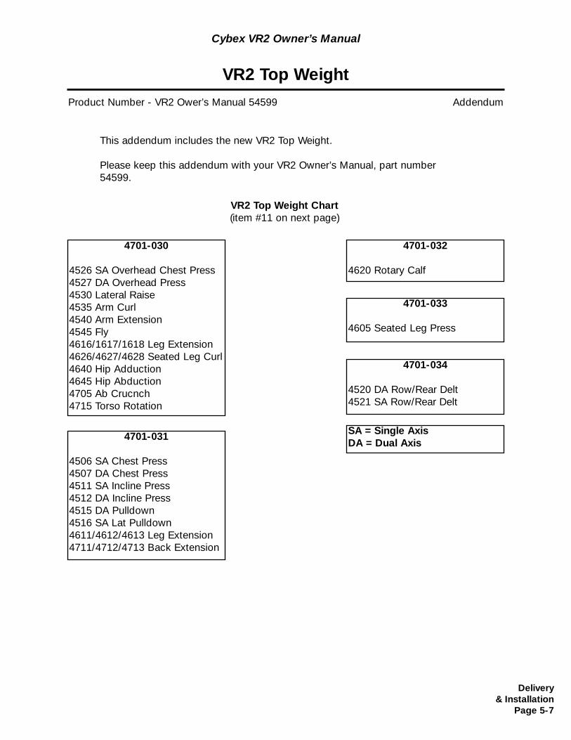
VR2 Top Weight
Product Number - VR2 Ower’s Manual 54599 Addendum
This addendum includes the new VR2 Top Weight.
Please keep this addendum with your VR2 Owner’s Manual, part number54599.
4701-030
4526 SA Overhead Chest Press4527 DA Overhead Press4530 Lateral Raise4535 Arm Curl4540 Arm Extension4545 Fly4616/1617/1618 Leg Extension4626/4627/4628 Seated Leg Curl4640 Hip Adduction4645 Hip Abduction4705 Ab Crucnch4715 Torso Rotation
4701-031
4506 SA Chest Press4507 DA Chest Press4511 SA Incline Press4512 DA Incline Press4515 DA Pulldown4516 SA Lat Pulldown4611/4612/4613 Leg Extension4711/4712/4713 Back Extension
4701-032
4620 Rotary Calf
4701-033
4605 Seated Leg Press
4701-034
4520 DA Row/Rear Delt4521 SA Row/Rear Delt
SA = Single AxisDA = Dual Axis
VR2 Top Weight Chart(item #11 on next page)
Delivery& Installation
Page 5-7
Cybex VR2 Owner’s Manual
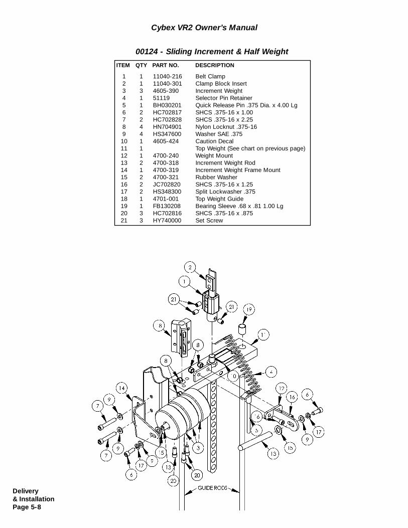
00124 - Sliding Increment & Half Weight
1 1 11040-216 Belt Clamp2 1 11040-301 Clamp Block Insert3 3 4605-390 Increment Weight4 1 51119 Selector Pin Retainer5 1 BH030201 Quick Release Pin .375 Dia. x 4.00 Lg6 2 HC702817 SHCS .375-16 x 1.007 2 HC702828 SHCS .375-16 x 2.258 4 HN704901 Nylon Locknut .375-169 4 HS347600 Washer SAE .37510 1 4605-424 Caution Decal11 1 Top Weight (See chart on previous page)12 1 4700-240 Weight Mount13 2 4700-318 Increment Weight Rod14 1 4700-319 Increment Weight Frame Mount15 2 4700-321 Rubber Washer16 2 JC702820 SHCS .375-16 x 1.2517 2 HS348300 Split Lockwasher .37518 1 4701-001 Top Weight Guide19 1 FB130208 Bearing Sleeve .68 x .81 1.00 Lg20 3 HC702816 SHCS .375-16 x .87521 3 HY740000 Set Screw
ITEM QTY PART NO. DESCRIPTION
Delivery& InstallationPage 5-8
Cybex VR2 Owner’s Manual
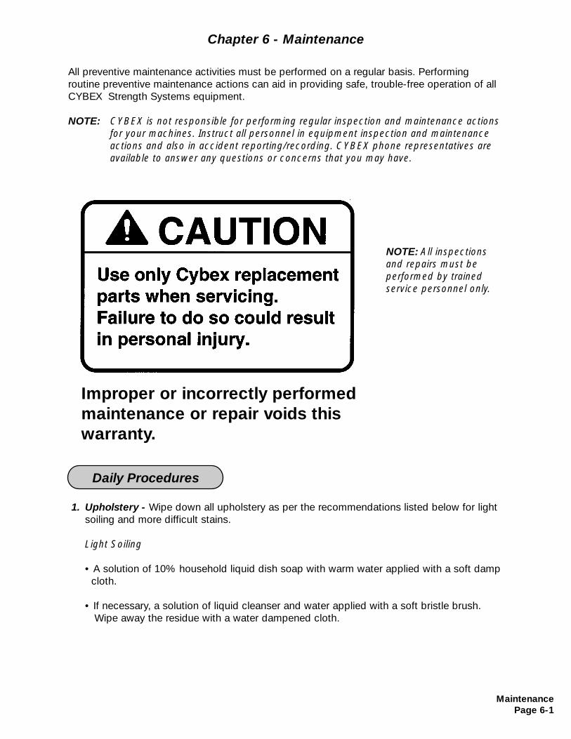
All preventive maintenance activities must be performed on a regular basis. Performing routine preventive maintenance actions can aid in providing safe, trouble-free operation of allCYBEX Strength Systems equipment.
NOTE: CYBEX is not responsible for performing regular inspection and maintenance actions for your machines. Instruct all personnel in equipment inspection and maintenance actions and also in accident reporting/recording. CYBEX phone representatives are available to answer any questions or concerns that you may have.
MaintenancePage 6-1
1. Upholstery - Wipe down all upholstery as per the recommendations listed below for light soiling and more difficult stains.
Light Soiling
• A solution of 10% household liquid dish soap with warm water applied with a soft damp cloth.
• If necessary, a solution of liquid cleanser and water applied with a soft bristle brush. Wipe away the residue with a water dampened cloth.
Chapter 6 - Maintenance
Daily Procedures
NOTE: All inspectionsand repairs must be performed by trained service personnel only.
Improper or incorrectly performedmaintenance or repair voids this warranty.
MaintenancePage 6-2
More Difficult Stains
• Dampen a soft white cloth with a solution of household bleach (sodium hypochlorite), 10% bleach, 90% water. Rub gently. Rinse with a water dampened cloth to remove bleach concentration.
• The same procedure can be used with full strength household bleach, if necessary.
• Allow bleach to puddle on the affected area or apply with a soaked cloth for approximately 30 minutes. Rinse with a water dampened cloth to remove any remaining bleach concentration.
Alternative Method for Difficult Stains
• Dampen a soft white cloth with rubbing alcohol and rub gently. Rinse with a water dampened cloth to remove any remaining rubbing alcohol concentration.
NOTE: To restore luster, a light coat of spray furniture wax can be used. Apply for 30 seconds and follow with a light buffing using a clean white cloth.
Please Review Carefully
When using strong cleaning agents such as rubbing alcohol or bleach, it is advisable to first test in an inconspicuous area. Other cleaning agents may contain harsh or unknown solvents and are subject to formula changes by the product manufacturer without notice. Should you desire to use other cleaning agents, carefully try them in an inconspicuous area to determine potential damage to the material. Never use harsh solvents or cleaners which are intended for industrial applications. To clean stained or soiled areas, a soft whitecloth is recommended. Avoid use of paper towels.
Cleaning products may be harmful/irritating to your skin, eyes, etc. Use protective gloves and eye protection. Do not inhale or swallow any cleaning product. Protect surrounding area/clothing from exposure. Use in a well ventilated area. Follow all product manufacturer’s warnings. CYBEX and its vendors cannot be held responsible for damage or injuries resulting from the use or misuse of cleaning products.
2. Frames - Wipe down all frames using a mild solution of warm water and car wash soap. Be sure to dry thoroughly. AVOID acid or chlorine based cleaners and also cleaners containing abrasives as these could scratch or damage the equipment.
3. Chrome - Clean chrome tubes, first using chrome polish and then using a car wax seal. Neutral cleaners with a pH between 5.5 and 8.5 are recommended. Be sure to dry thoroughly. AVOID acid or chlorine based cleaners and also cleaners containing abrasivesas these could scratch or damage the equipment.
Cybex VR2 Owner’s Manual
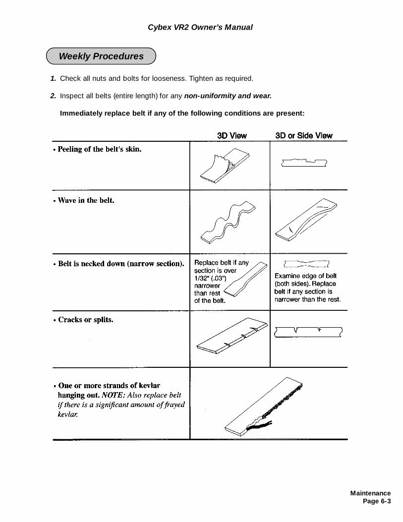
MaintenancePage 6-3
Cybex VR2 Owner’s Manual
1. Check all nuts and bolts for looseness. Tighten as required.
2. Inspect all belts (entire length) for any non-uniformity and wear.
Immediately replace belt if any of the following conditions are present:
Weekly Procedures
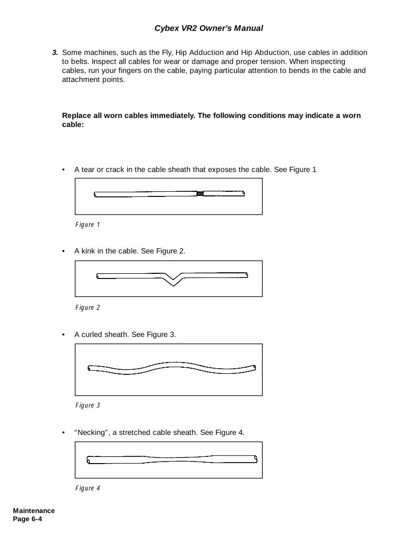
MaintenancePage 6-4
3. Some machines, such as the Fly, Hip Adduction and Hip Abduction, use cables in addition to belts. Inspect all cables for wear or damage and proper tension. When inspecting cables, run your fingers on the cable, paying particular attention to bends in the cable and attachment points.
Replace all worn cables immediately. The following conditions may indicate a worn cable:
• A tear or crack in the cable sheath that exposes the cable. See Figure 1
• A kink in the cable. See Figure 2.
• A curled sheath. See Figure 3.
• “Necking”, a stretched cable sheath. See Figure 4.
Figure 1
Figure 2
Figure 3
Figure 4
Cybex VR2 Owner’s Manual
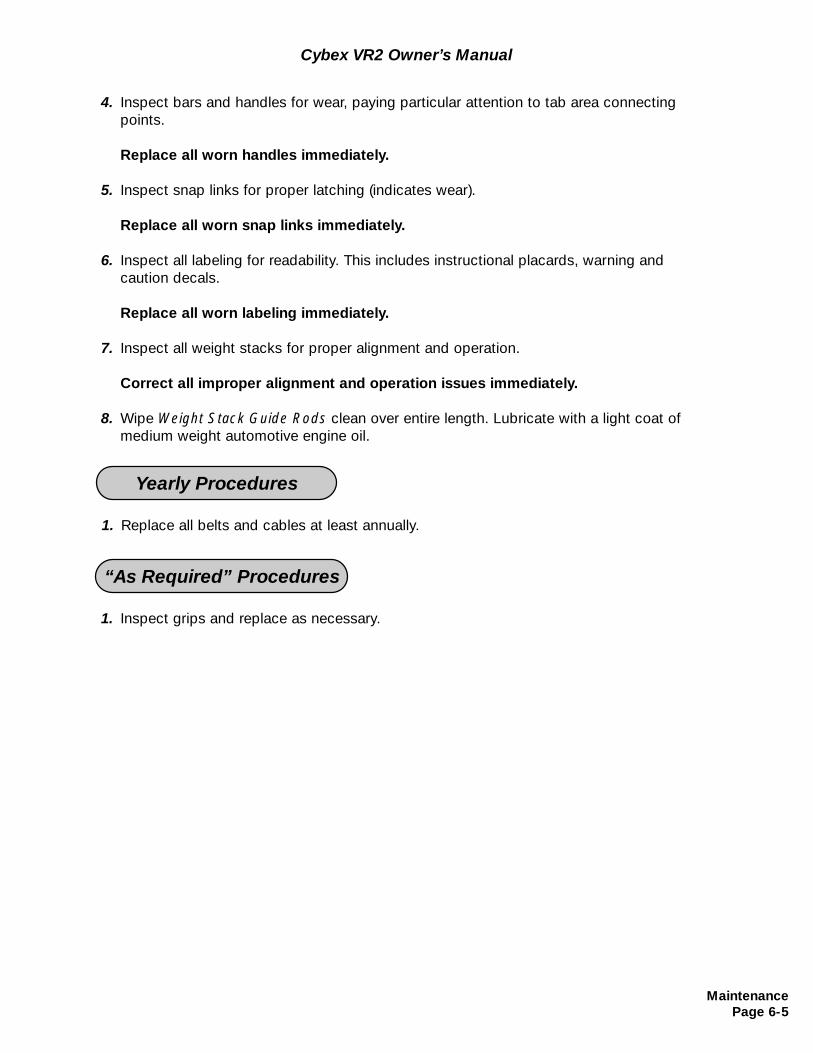
MaintenancePage 6-5
1. Replace all belts and cables at least annually.
Yearly Procedures
Cybex VR2 Owner’s Manual
4. Inspect bars and handles for wear, paying particular attention to tab area connecting points.
Replace all worn handles immediately.
5. Inspect snap links for proper latching (indicates wear).
Replace all worn snap links immediately.
6. Inspect all labeling for readability. This includes instructional placards, warning and caution decals.
Replace all worn labeling immediately.
7. Inspect all weight stacks for proper alignment and operation.
Correct all improper alignment and operation issues immediately.
8. Wipe Weight Stack Guide Rods clean over entire length. Lubricate with a light coat of medium weight automotive engine oil.
1. Inspect grips and replace as necessary.
“As Required” Procedures

MaintenancePage 6-6
Cybex VR2 Owner’s Manual
(This page intentionally left blank)
ServicePage 7-1
Chapter 7 - Service
This section contains a recommended belt installation and removal, grip replacement proce-dure, pivot shaft installation and removal, as well as service information for each machine.See the caution statement shown below when replacing parts.
General
NOTE: All inspectionsand repairs must be performed by trained service personnel only.
Improper or incorrectly performedmaintenance or repair voids this warranty.
ServicePage 7-2
Cybex VR2 Owner’s Manual
(This page intentionally left blank)
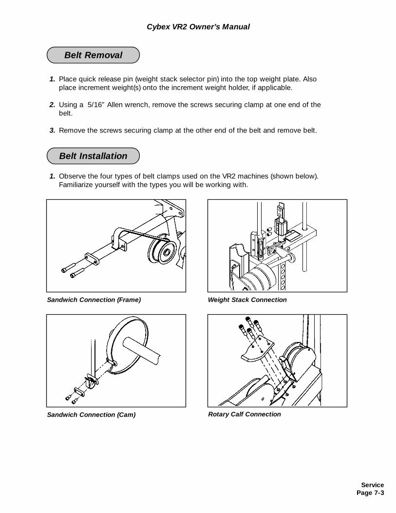
ServicePage 7-3
1. Place quick release pin (weight stack selector pin) into the top weight plate. Also place increment weight(s) onto the increment weight holder, if applicable.
2. Using a 5/16” Allen wrench, remove the screws securing clamp at one end of the belt.
3. Remove the screws securing clamp at the other end of the belt and remove belt.
1. Observe the four types of belt clamps used on the VR2 machines (shown below). Familiarize yourself with the types you will be working with.
Belt Removal
Belt Installation
Cybex VR2 Owner’s Manual
Sandwich Connection (Frame) Weight Stack Connection
Sandwich Connection (Cam) Rotary Calf Connection
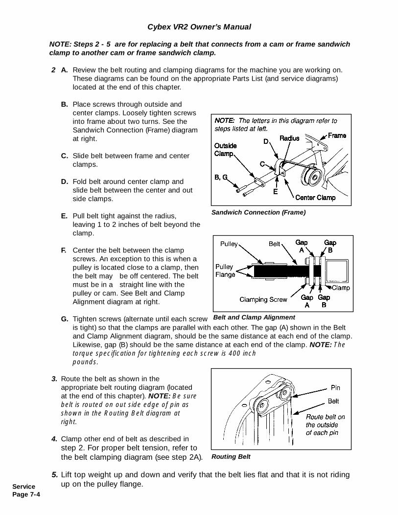
NOTE: Steps 2 - 5 are for replacing a belt that connects from a cam or frame sandwichclamp to another cam or frame sandwich clamp.
2 A. Review the belt routing and clamping diagrams for the machine you are working on. These diagrams can be found on the appropriate Parts List (and service diagrams) located at the end of this chapter.
B. Place screws through outside and center clamps. Loosely tighten screws into frame about two turns. See the Sandwich Connection (Frame) diagram at right.
C. Slide belt between frame and center clamps.
D. Fold belt around center clamp and slide belt between the center and outside clamps.
E. Pull belt tight against the radius, leaving 1 to 2 inches of belt beyond the clamp.
F. Center the belt between the clamp screws. An exception to this is when a pulley is located close to a clamp, then the belt may be off centered. The belt must be in a straight line with the pulley or cam. See Belt and Clamp Alignment diagram at right.
G. Tighten screws (alternate until each screw is tight) so that the clamps are parallel with each other. The gap (A) shown in the Belt and Clamp Alignment diagram, should be the same distance at each end of the clamp. Likewise, gap (B) should be the same distance at each end of the clamp. NOTE: The torque specification for tightening each screw is 400 inch pounds.
3. Route the belt as shown in the appropriate belt routing diagram (located at the end of this chapter). NOTE: Be sure belt is routed on out side edge of pin as shown in the Routing Belt diagram at right.
4. Clamp other end of belt as described in step 2. For proper belt tension, refer to the belt clamping diagram (see step 2A).
5. Lift top weight up and down and verify that the belt lies flat and that it is not riding up on the pulley flange.
Cybex VR2 Owner’s Manual
Routing Belt
ServicePage 7-4
Belt and Clamp Alignment
Sandwich Connection (Frame)
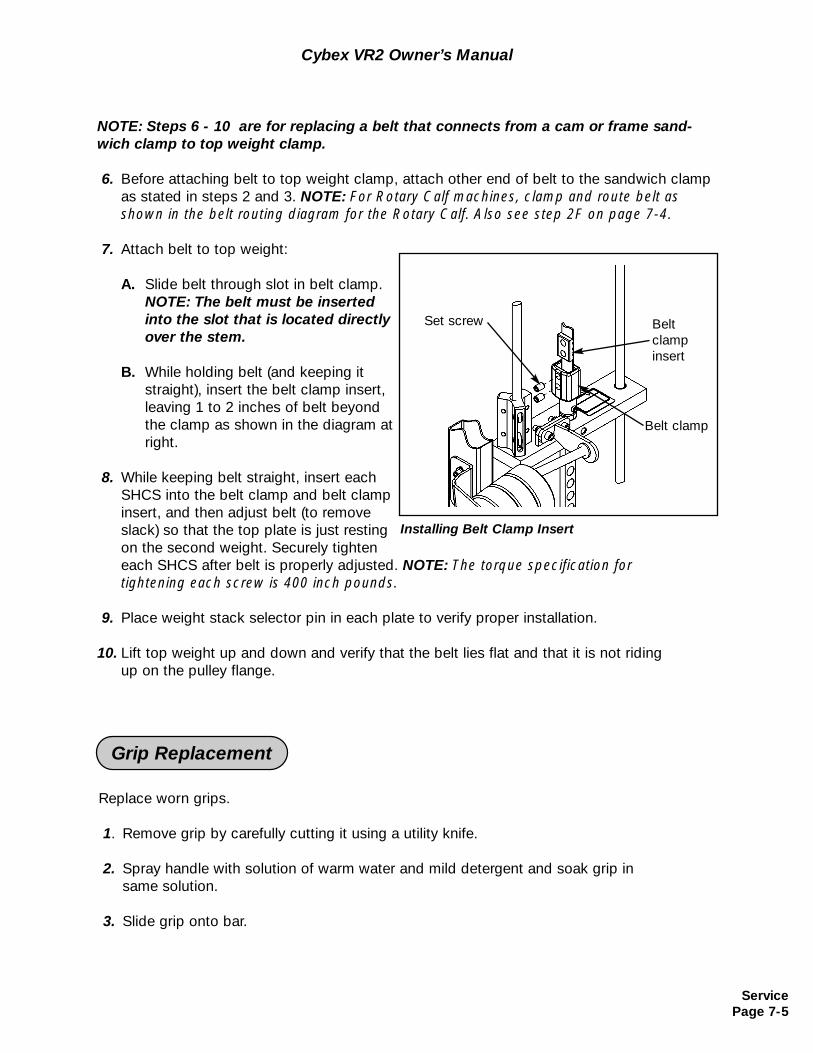
ServicePage 7-5
NOTE: Steps 6 - 10 are for replacing a belt that connects from a cam or frame sand-wich clamp to top weight clamp.
6. Before attaching belt to top weight clamp, attach other end of belt to the sandwich clamp as stated in steps 2 and 3. NOTE: For Rotary Calf machines, clamp and route belt as shown in the belt routing diagram for the Rotary Calf. Also see step 2F on page 7-4.
7. Attach belt to top weight:
A. Slide belt through slot in belt clamp. NOTE: The belt must be inserted into the slot that is located directly over the stem.
B. While holding belt (and keeping it straight), insert the belt clamp insert, leaving 1 to 2 inches of belt beyond the clamp as shown in the diagram at right.
8. While keeping belt straight, insert each SHCS into the belt clamp and belt clamp insert, and then adjust belt (to removeslack) so that the top plate is just resting on the second weight. Securely tighten each SHCS after belt is properly adjusted. NOTE: The torque specification for tightening each screw is 400 inch pounds.
9. Place weight stack selector pin in each plate to verify proper installation.
10. Lift top weight up and down and verify that the belt lies flat and that it is not riding up on the pulley flange.
Cybex VR2 Owner’s Manual
Replace worn grips.
1. Remove grip by carefully cutting it using a utility knife.
2. Spray handle with solution of warm water and mild detergent and soak grip in same solution.
3. Slide grip onto bar.
Grip Replacement
Installing Belt Clamp Insert
Belt clamp
Set screw Beltclampinsert
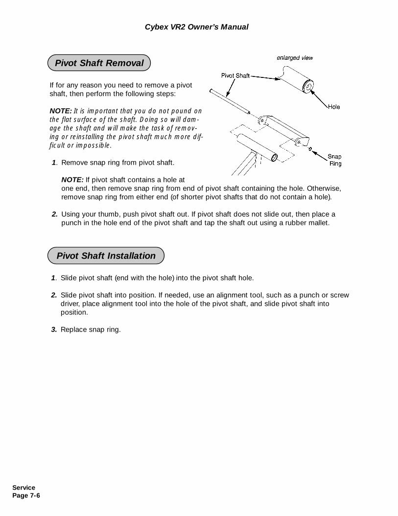
Cybex VR2 Owner’s Manual
ServicePage 7-6
If for any reason you need to remove a pivotshaft, then perform the following steps:
NOTE: It is important that you do not pound onthe flat surface of the shaft. Doing so will dam-age the shaft and will make the task of remov-ing or reinstalling the pivot shaft much more dif-ficult or impossible.
1. Remove snap ring from pivot shaft.
NOTE: If pivot shaft contains a hole at one end, then remove snap ring from end of pivot shaft containing the hole. Otherwise, remove snap ring from either end (of shorter pivot shafts that do not contain a hole).
2. Using your thumb, push pivot shaft out. If pivot shaft does not slide out, then place a punch in the hole end of the pivot shaft and tap the shaft out using a rubber mallet.
Pivot Shaft Removal
1. Slide pivot shaft (end with the hole) into the pivot shaft hole.
2. Slide pivot shaft into position. If needed, use an alignment tool, such as a punch or screwdriver, place alignment tool into the hole of the pivot shaft, and slide pivot shaft into position.
3. Replace snap ring.
Pivot Shaft Installation
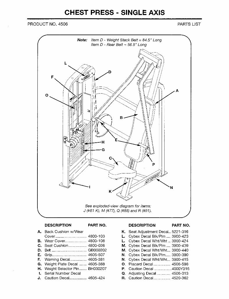
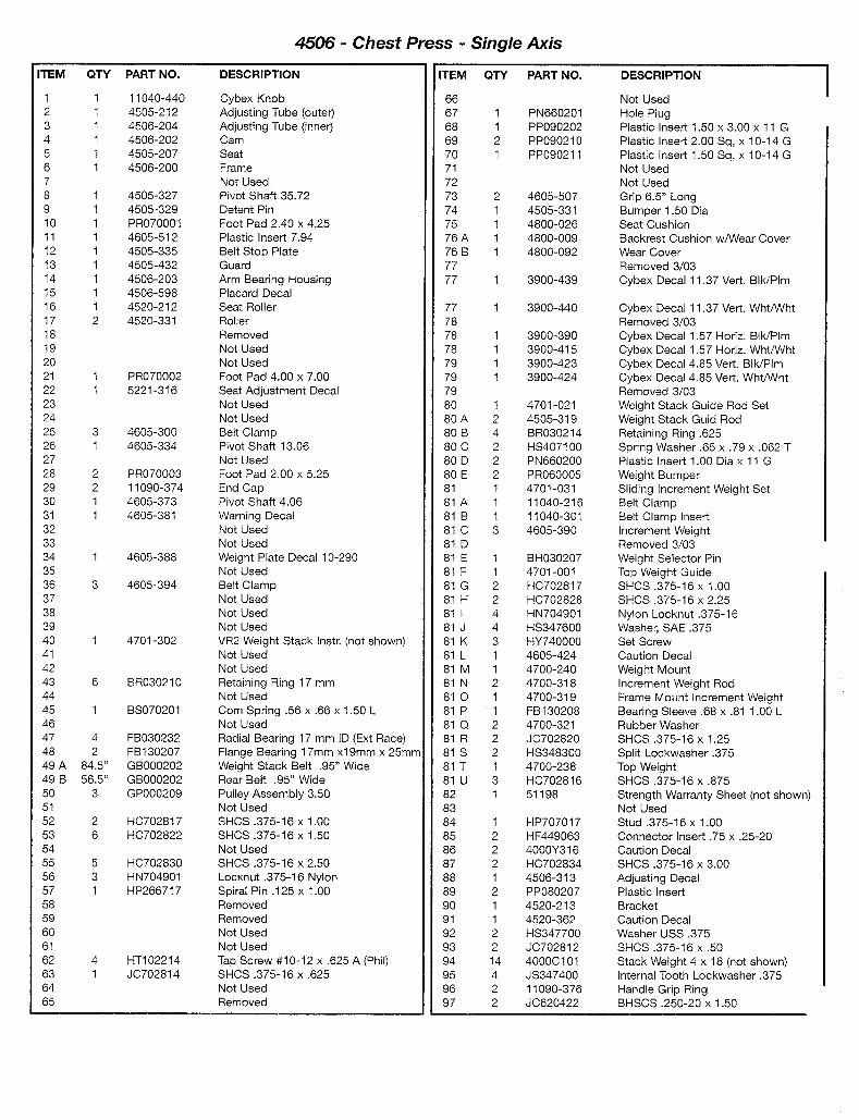
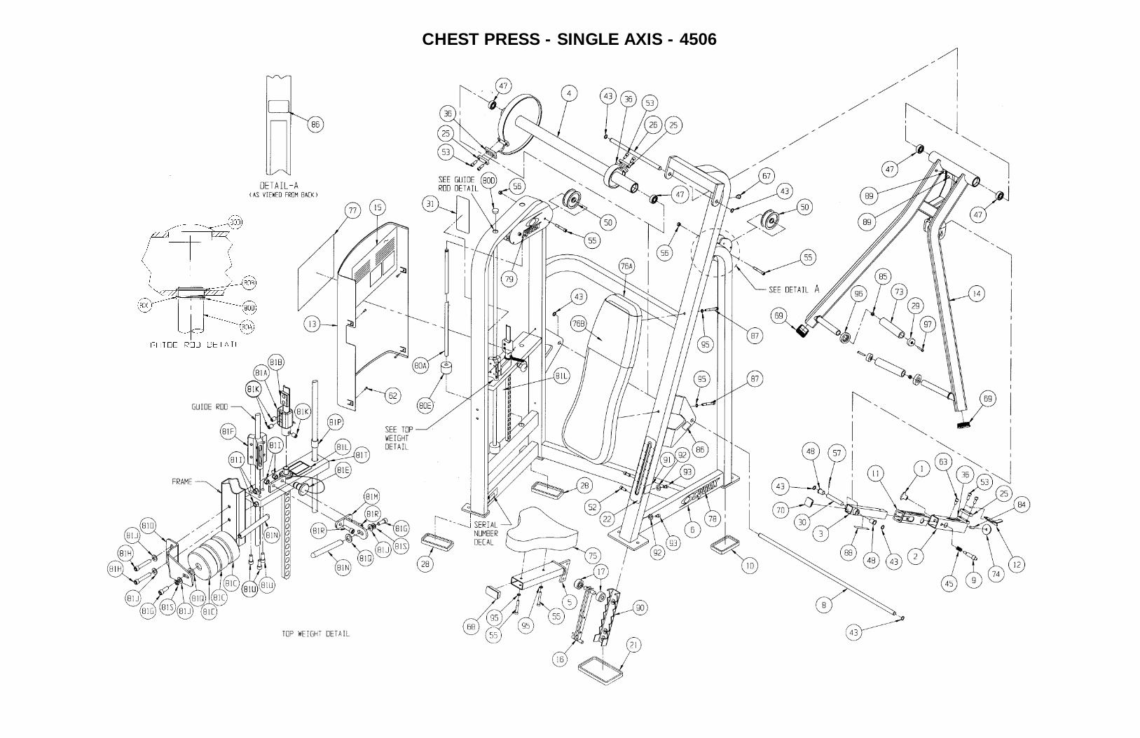
CHEST PRESS - SINGLE AXIS - 4506
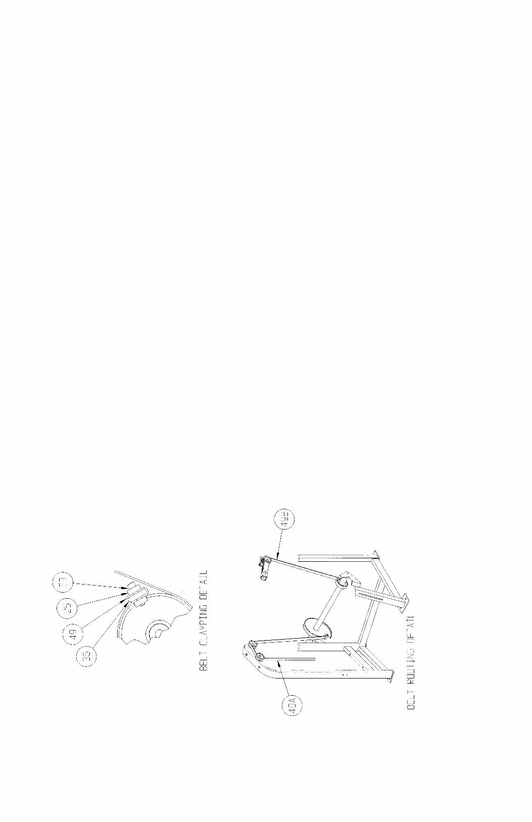
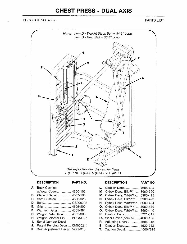
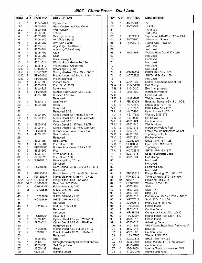
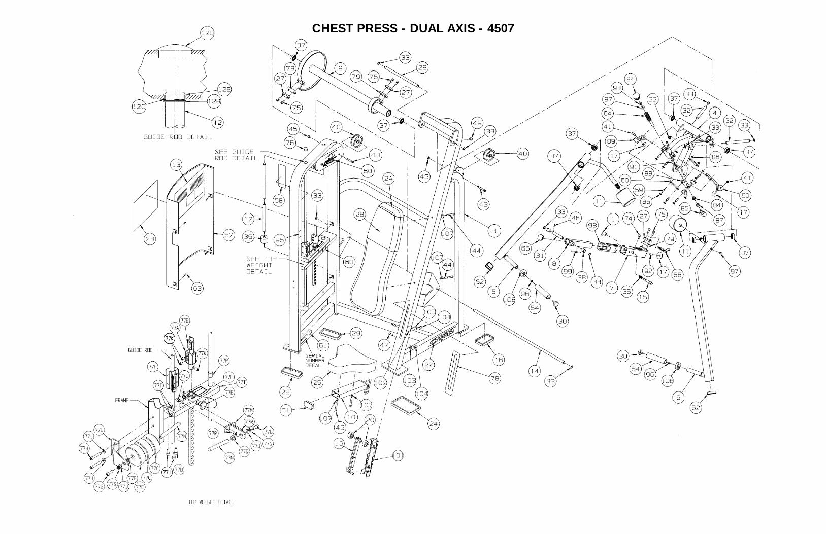
CHEST PRESS - DUAL AXIS - 4507
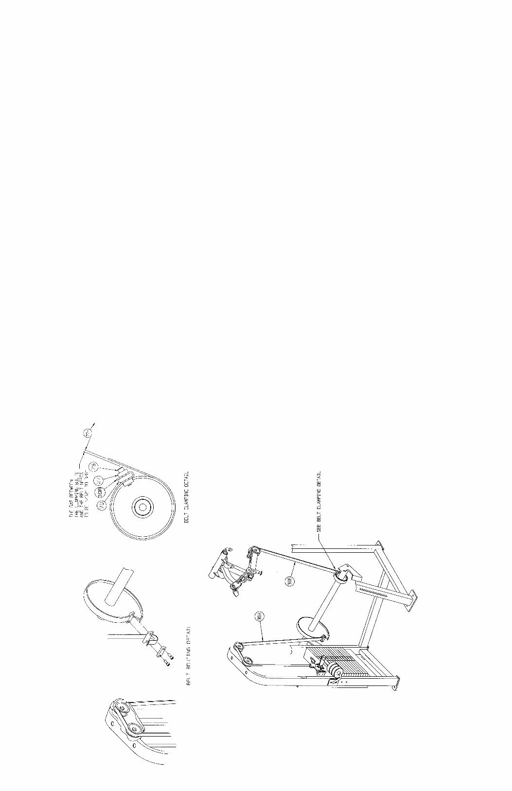
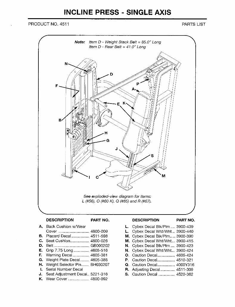
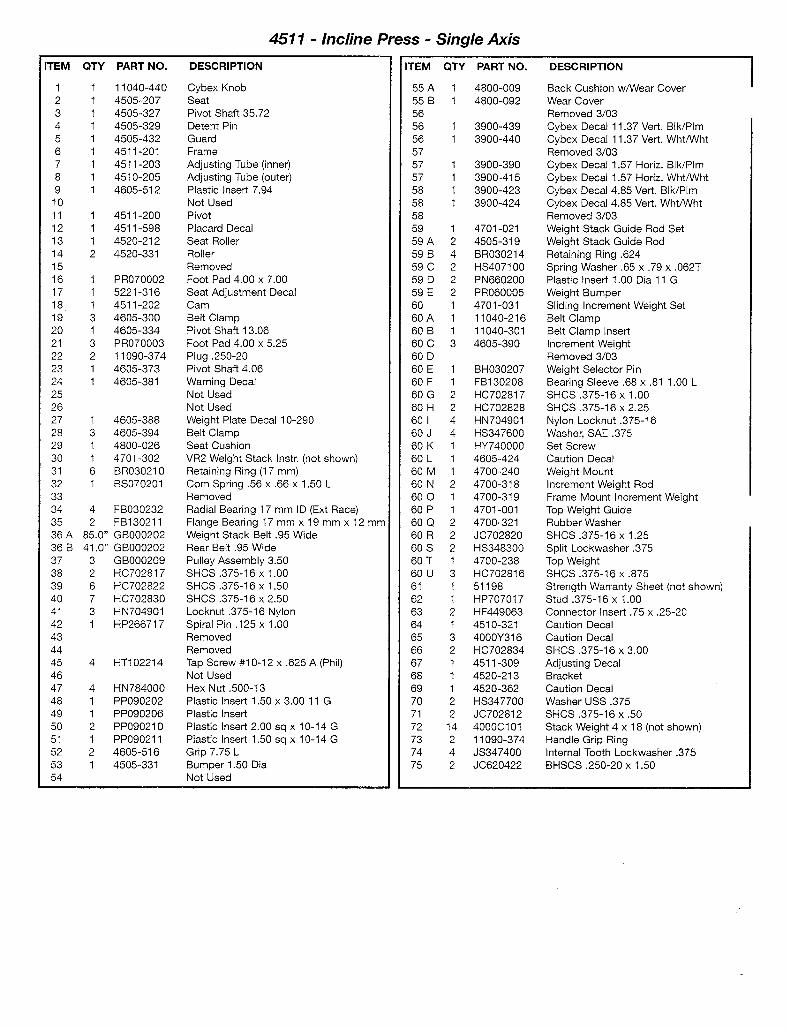
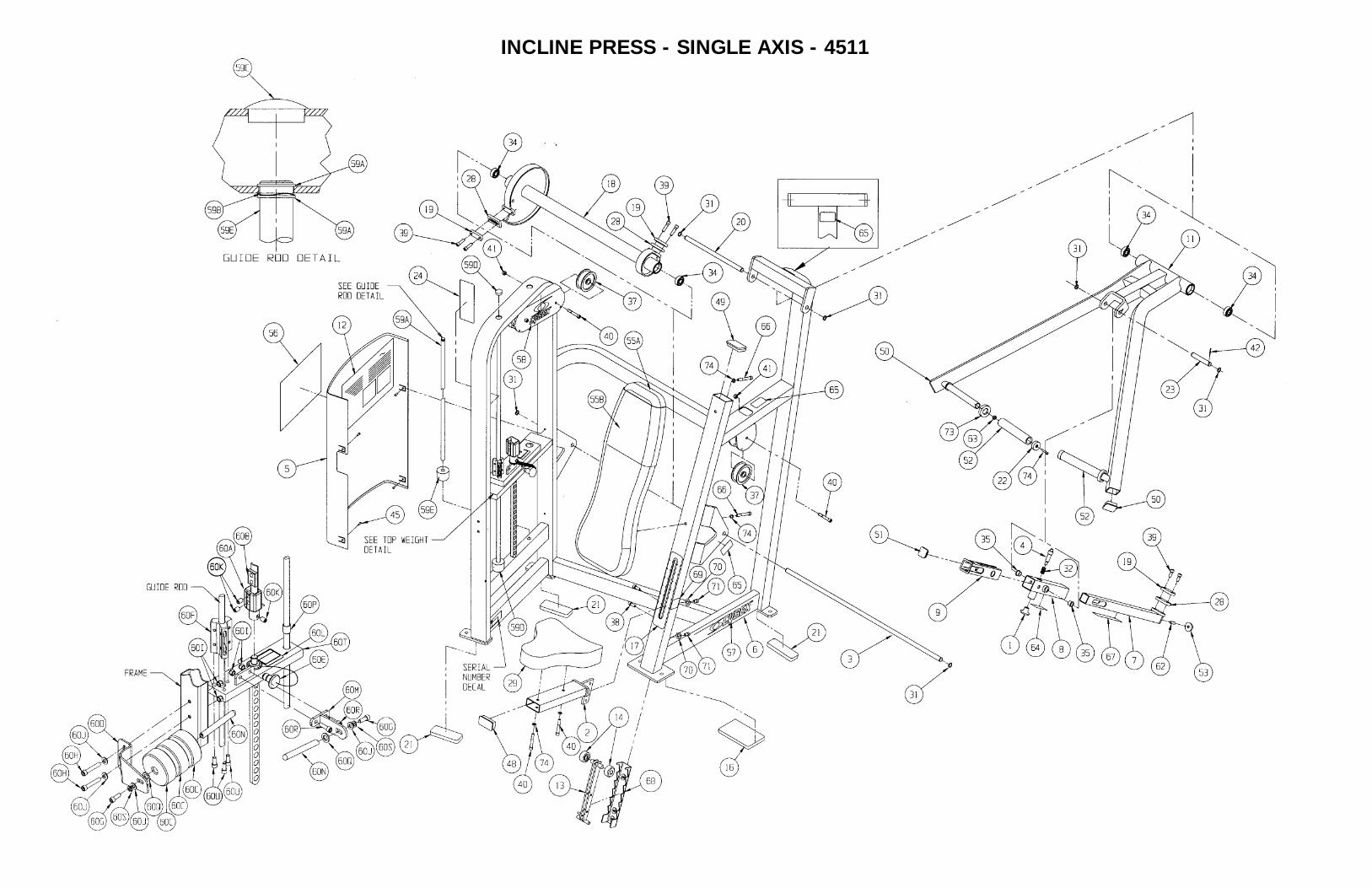
INCLINE PRESS - SINGLE AXIS - 4511
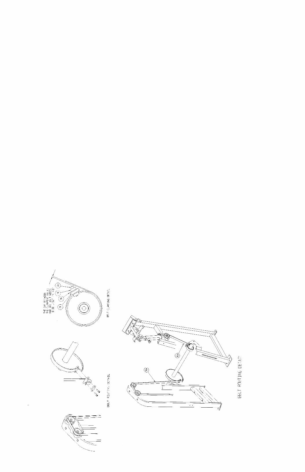
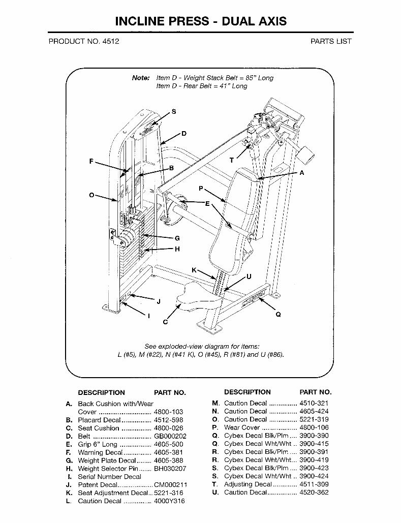
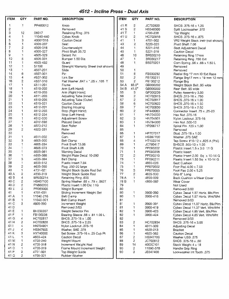
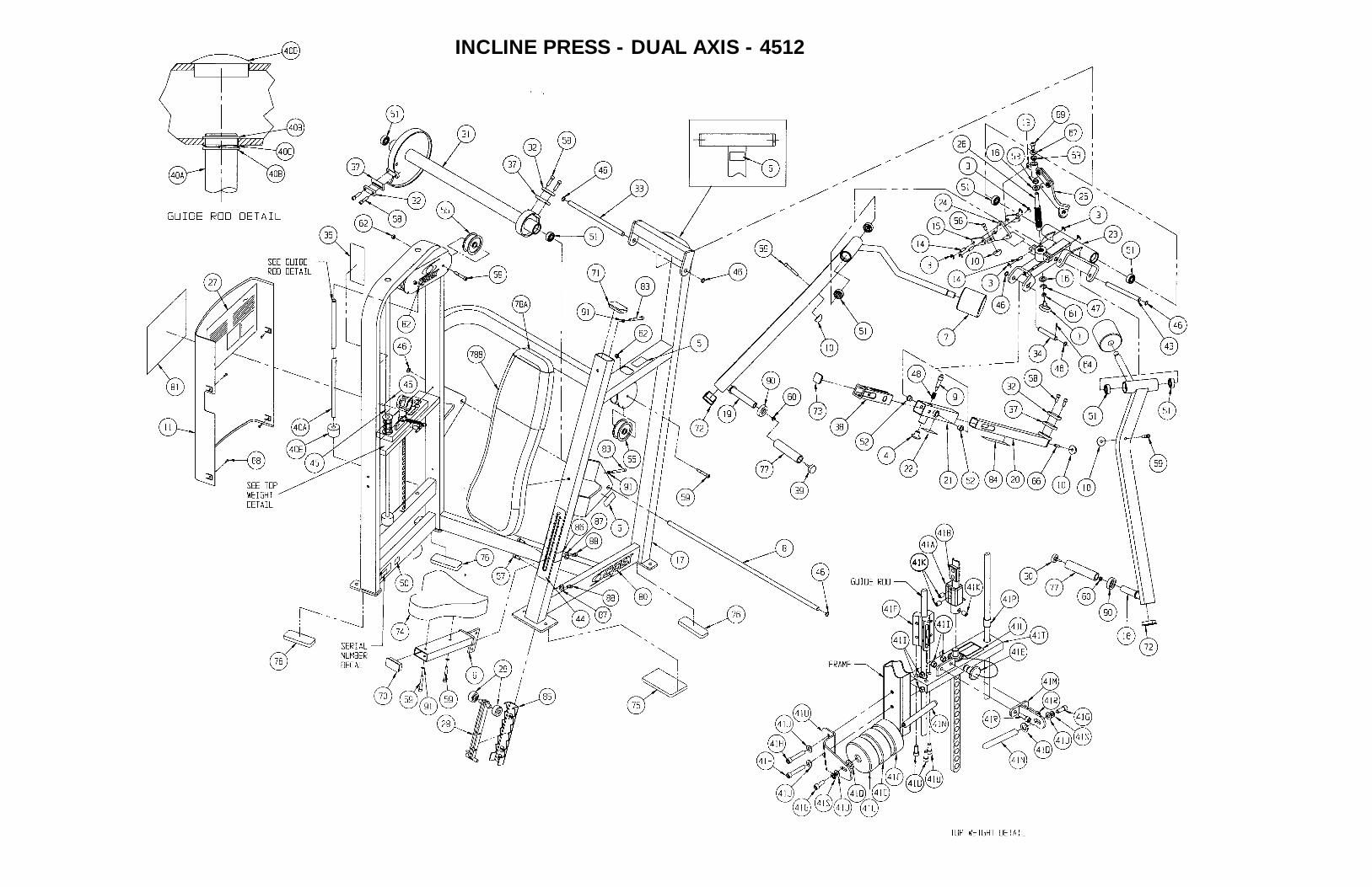
INCLINE PRESS - DUAL AXIS - 4512
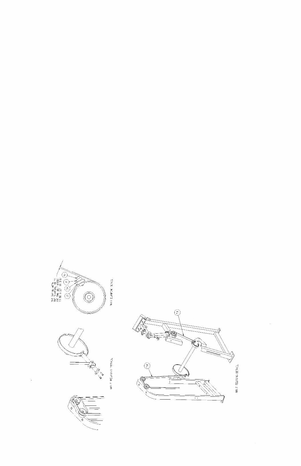
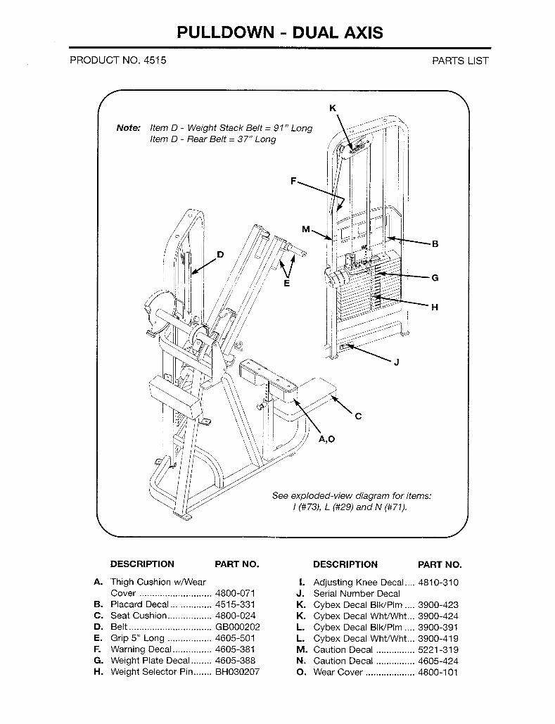
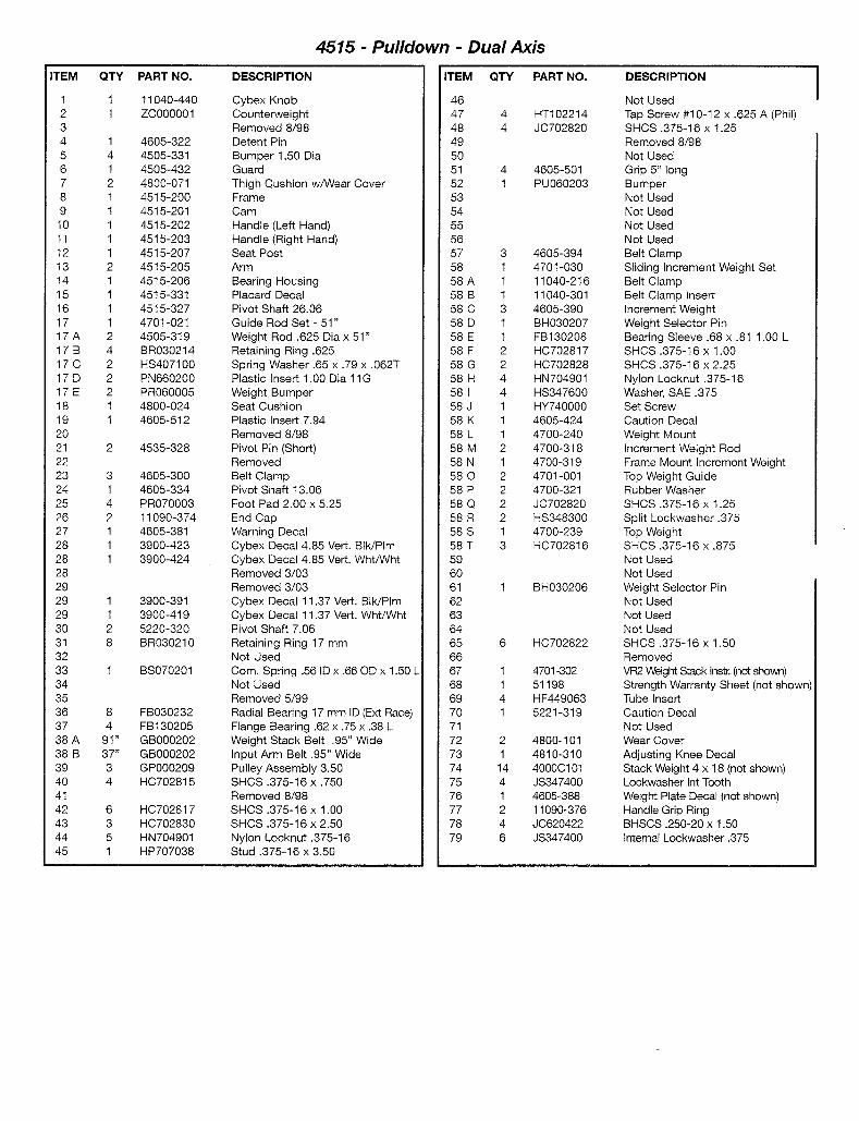

PULLDOWN - DUAL AXIS - 4515
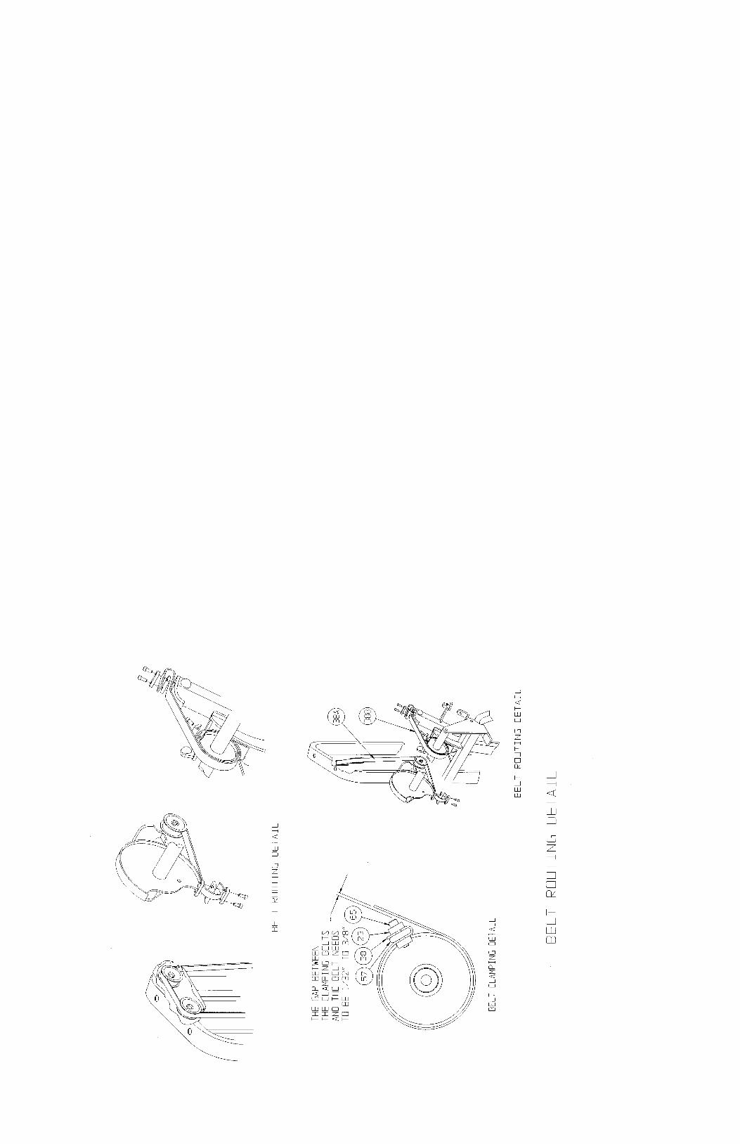
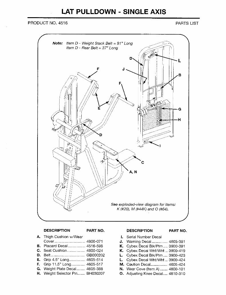
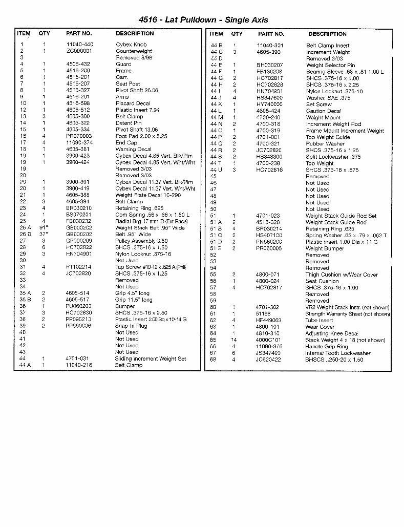
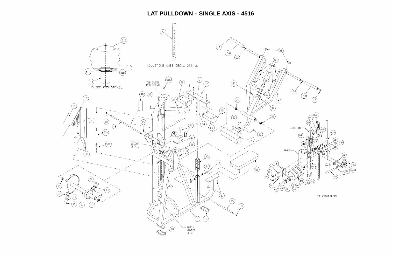
LAT PULLDOWN - SINGLE AXIS - 4516
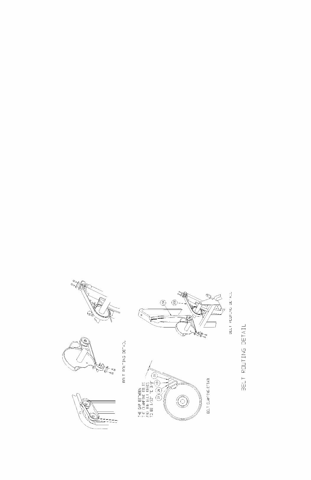
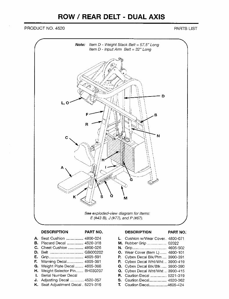
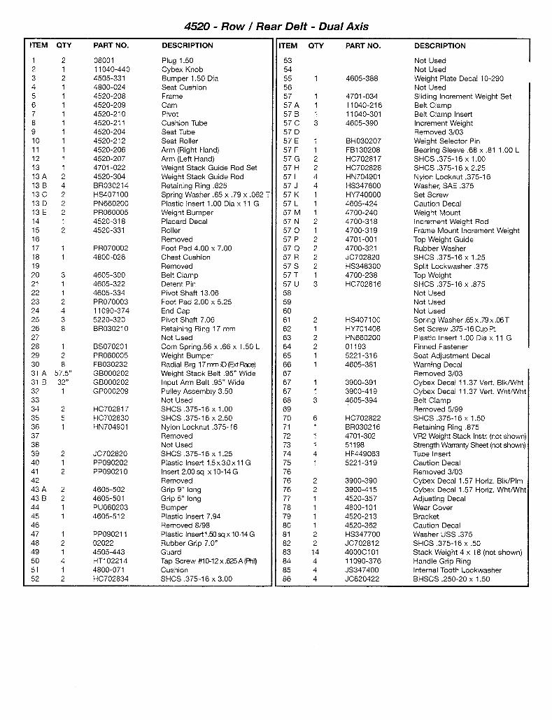
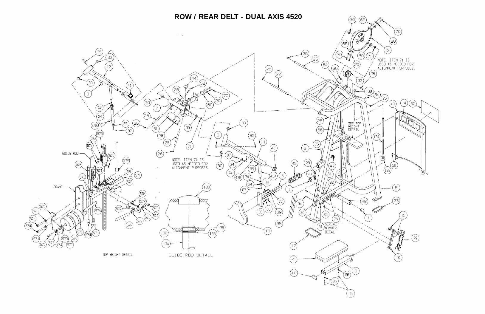
ROW / REAR DELT - DUAL AXIS 4520
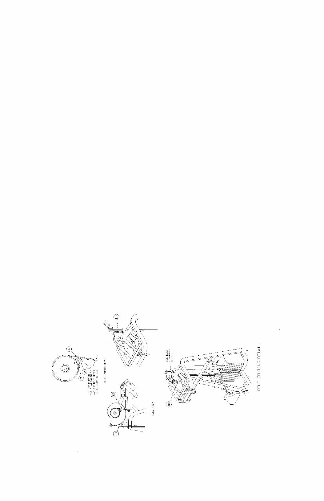
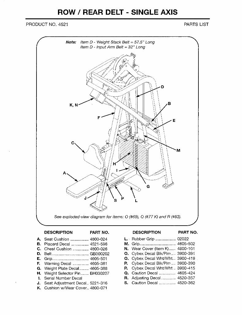
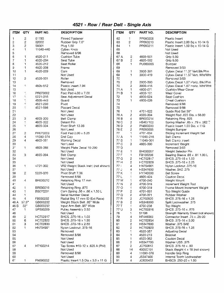
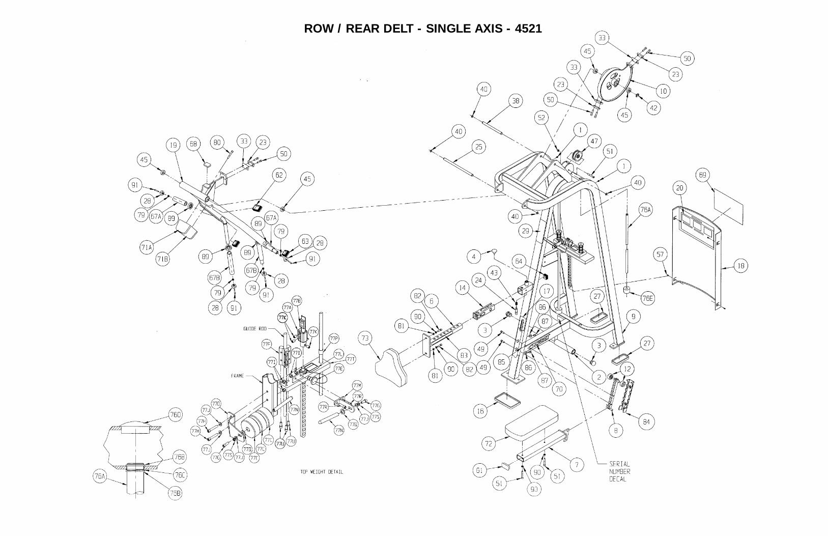
ROW / REAR DELT - SINGLE AXIS - 4521
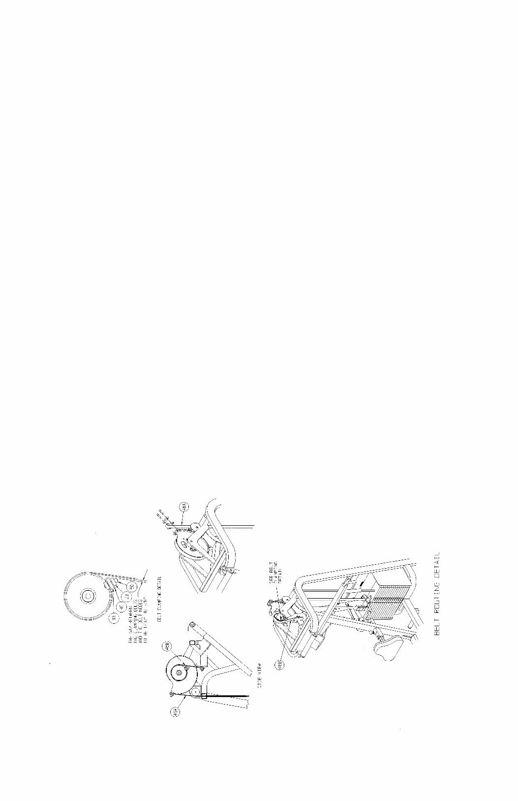
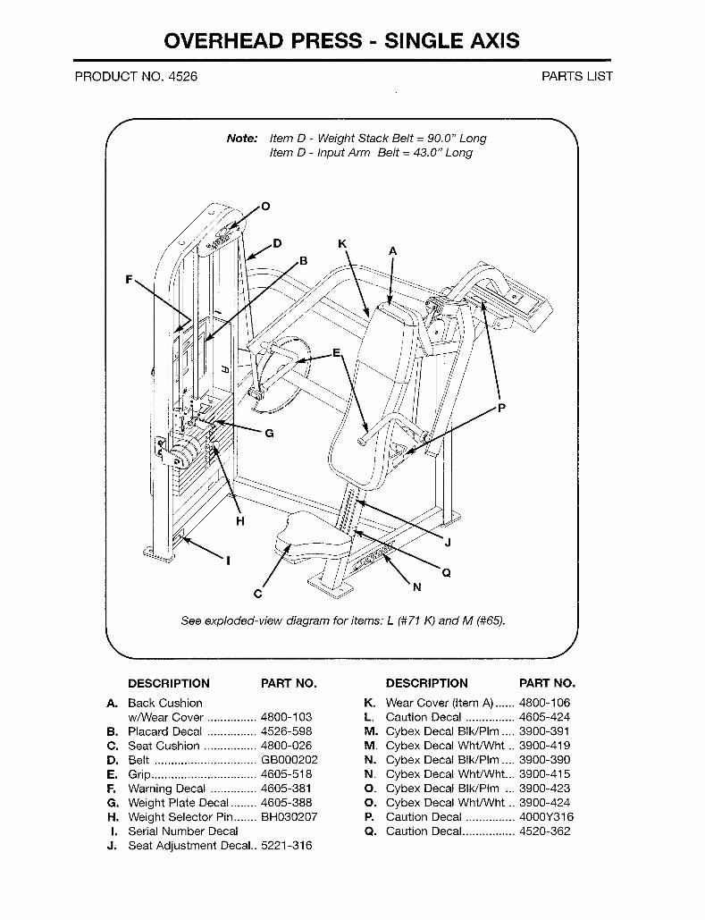
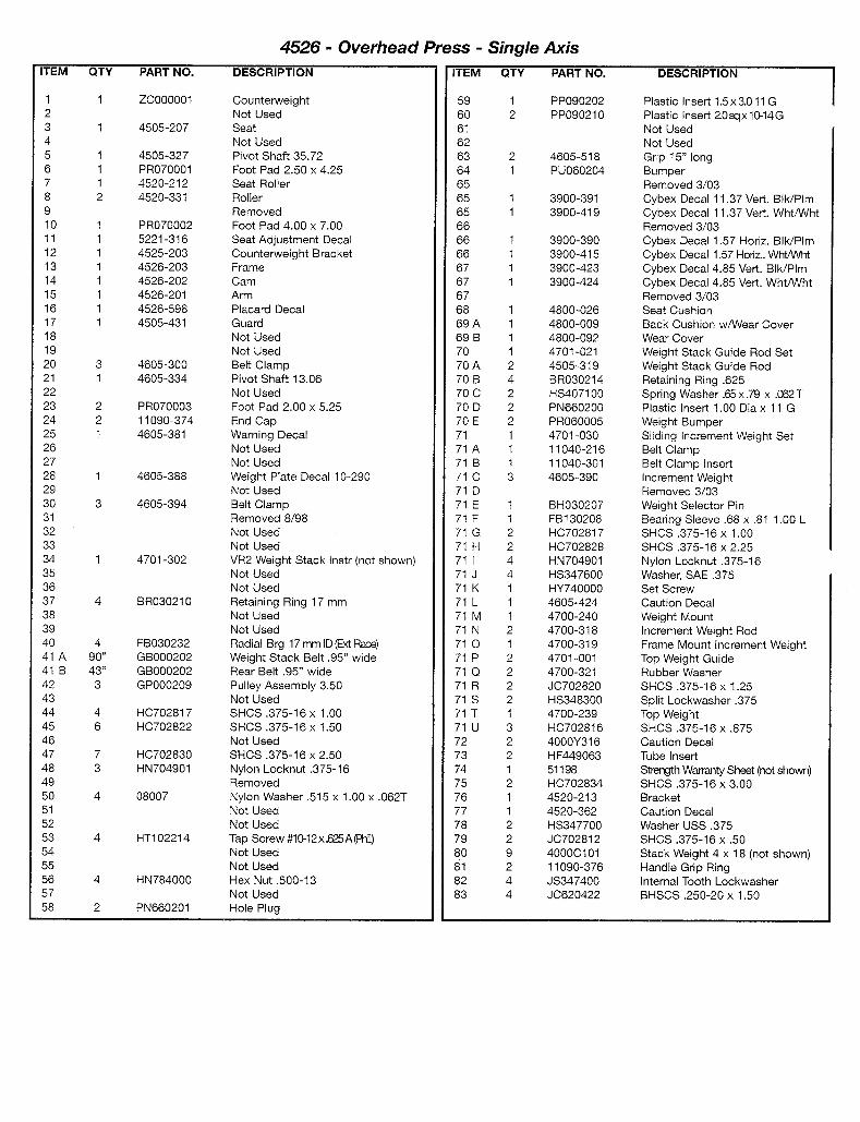
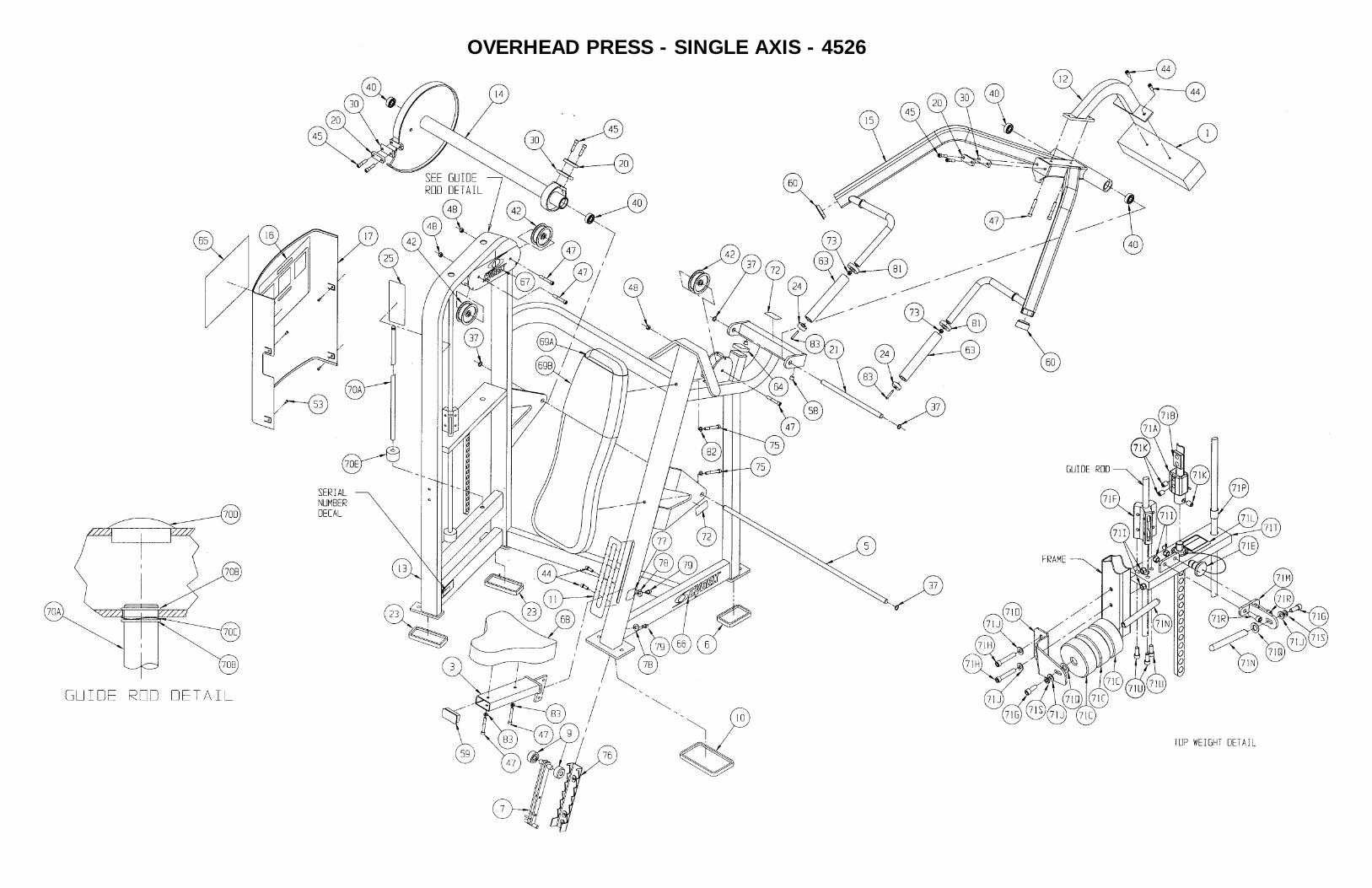
OVERHEAD PRESS - SINGLE AXIS - 4526

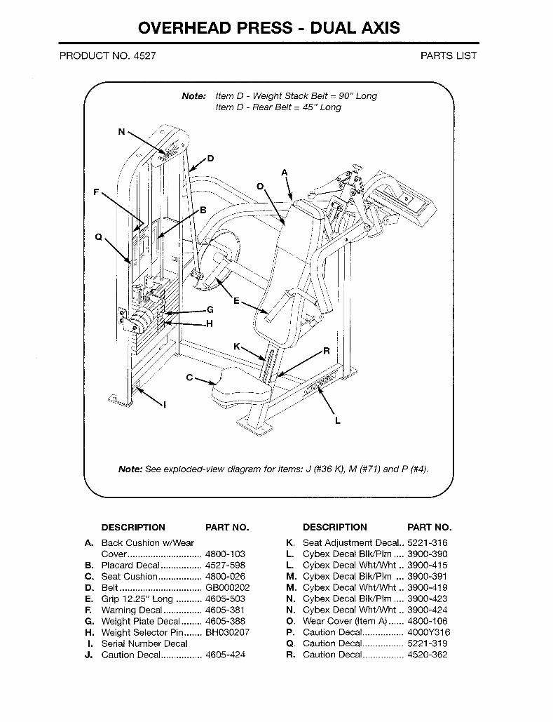
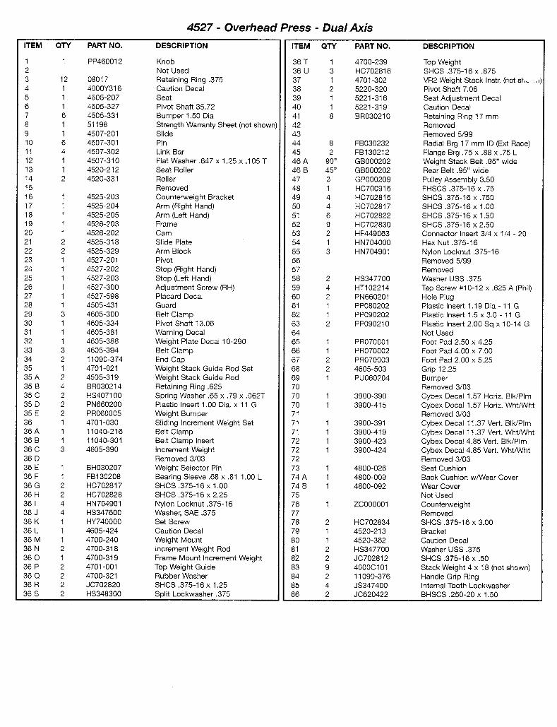
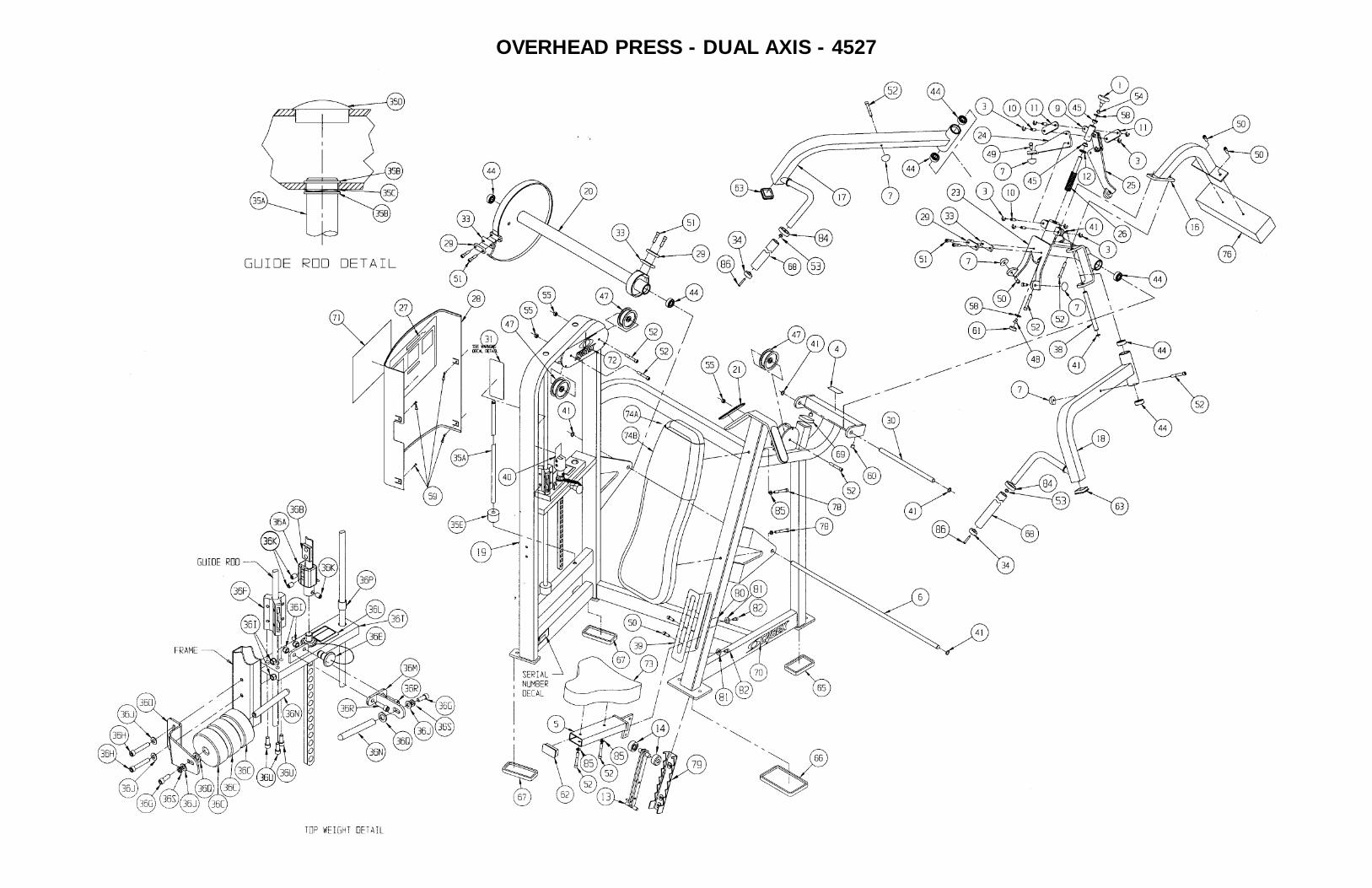
OVERHEAD PRESS - DUAL AXIS - 4527
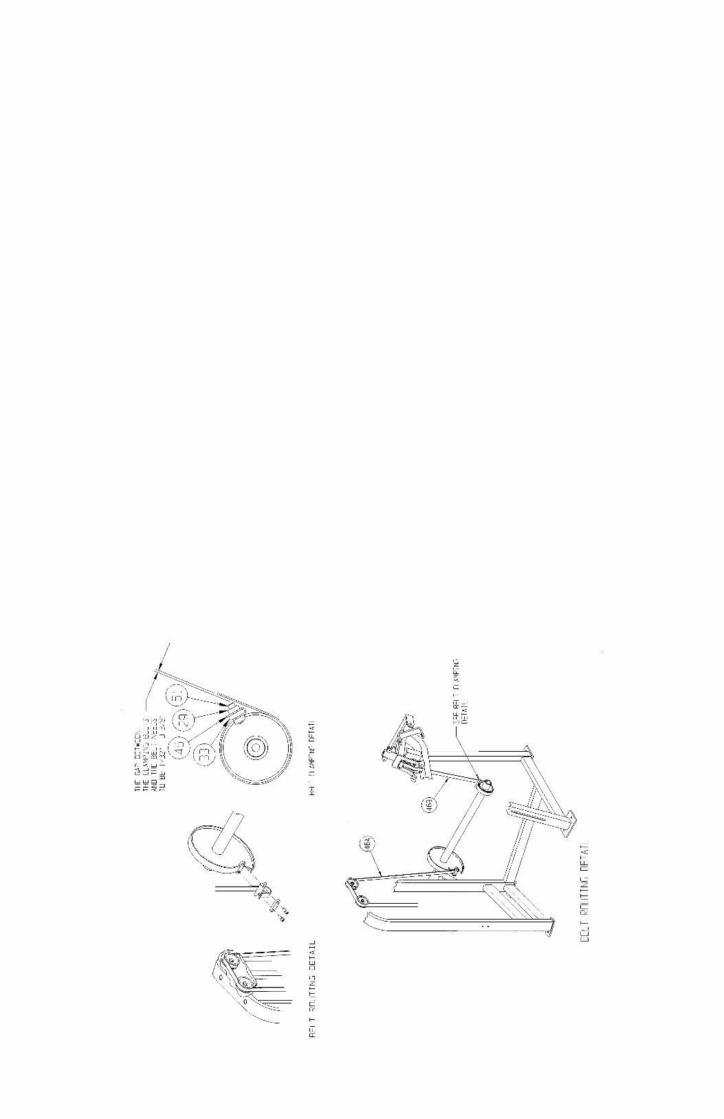
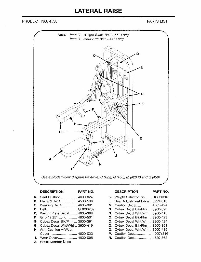
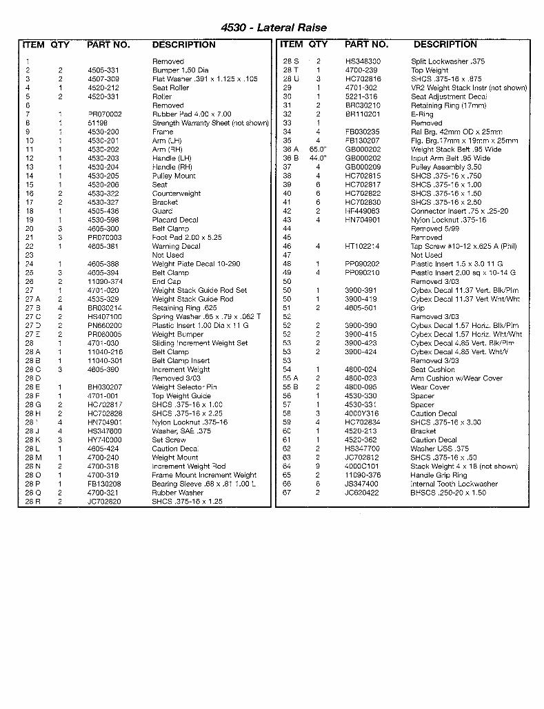
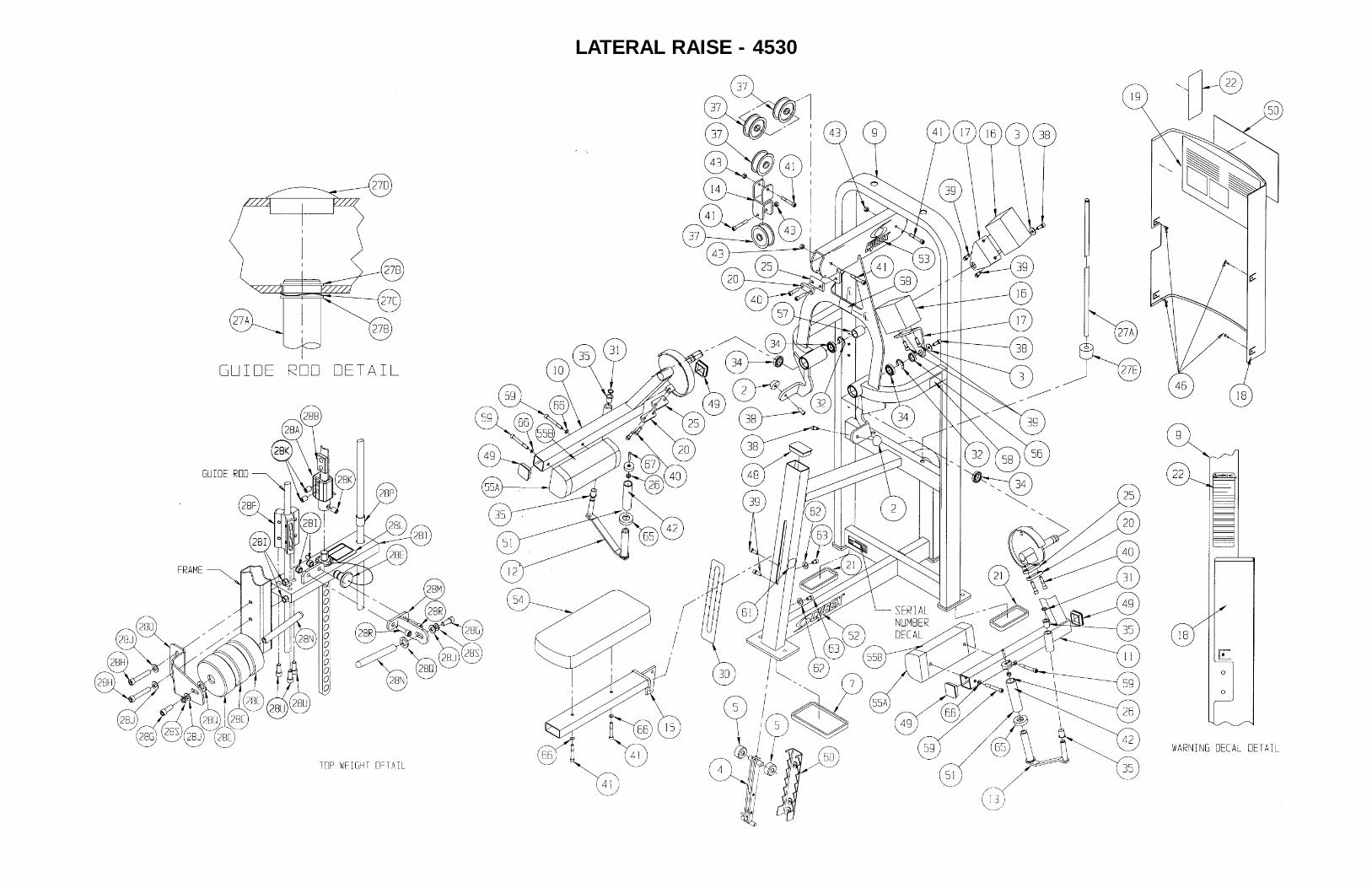
LATERAL RAISE - 4530
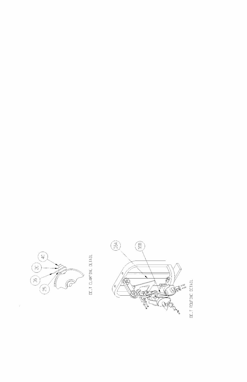
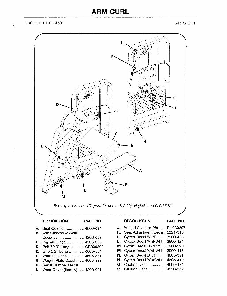
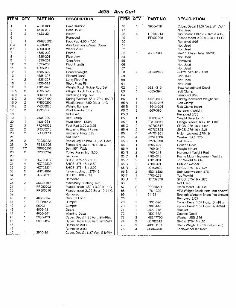
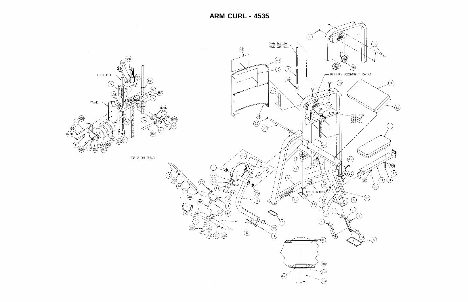
ARM CURL - 4535
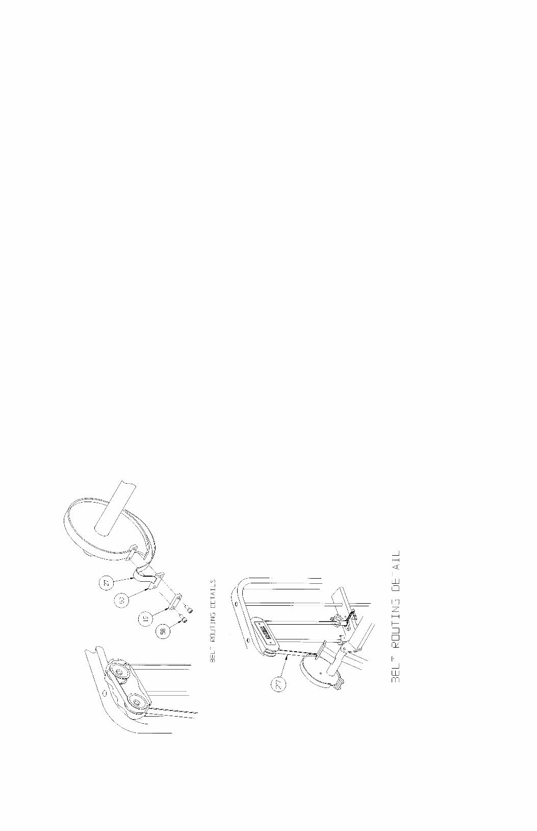
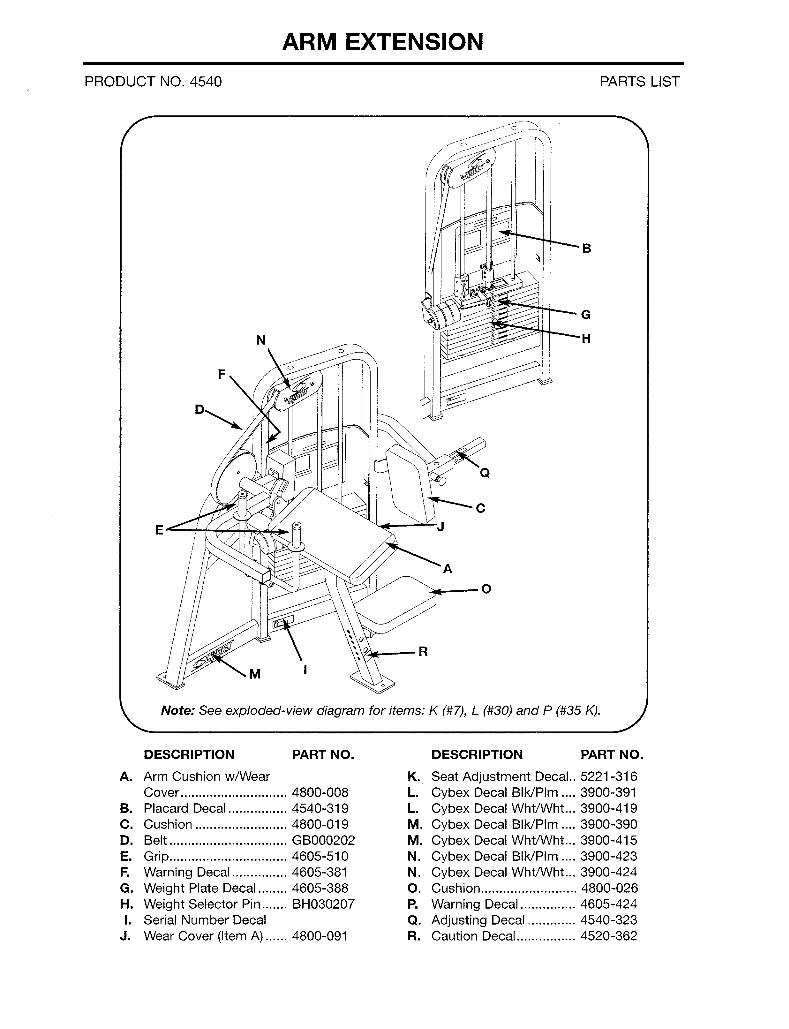
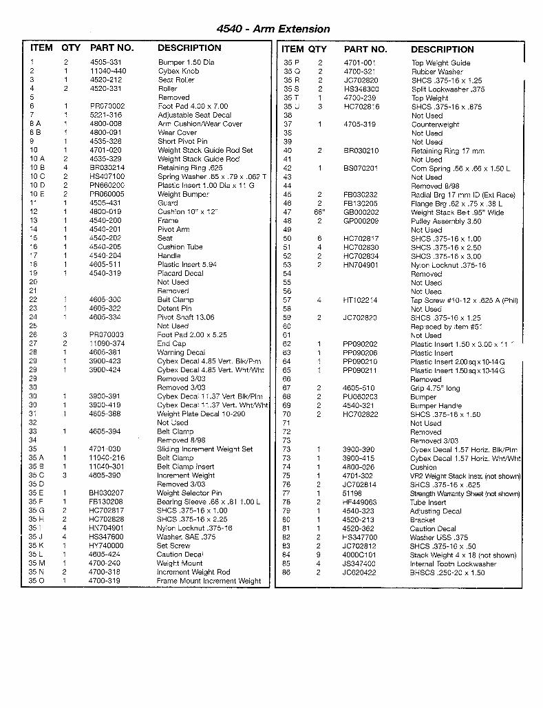
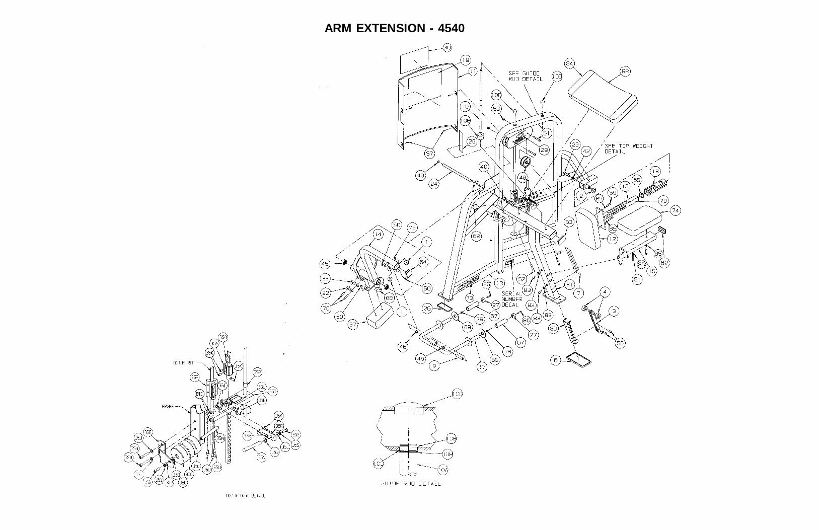
ARM EXTENSION - 4540
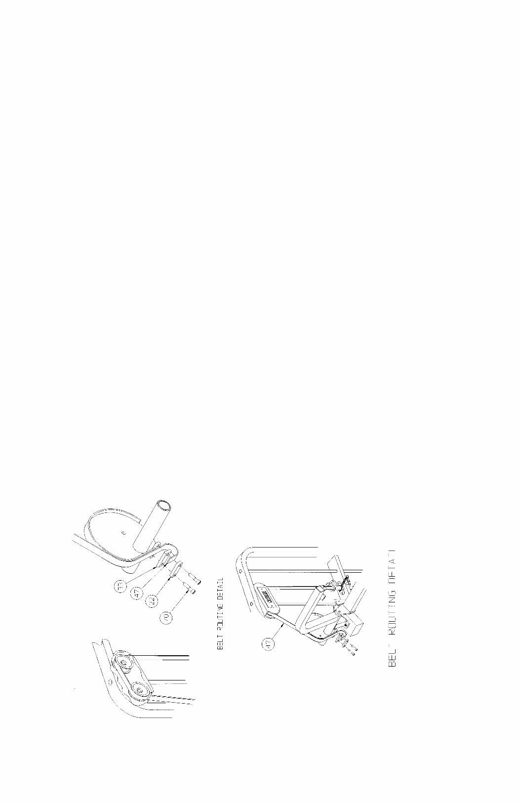
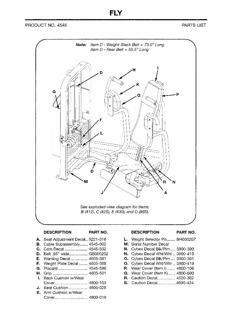
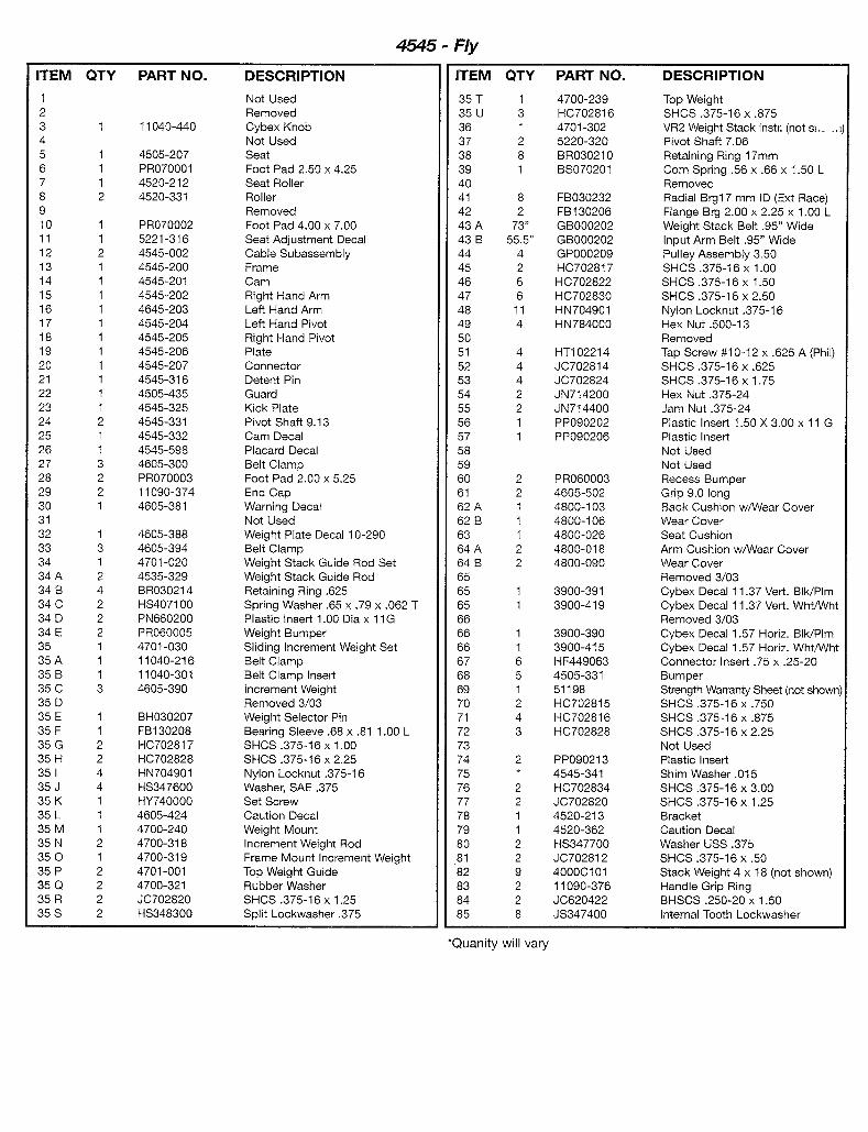
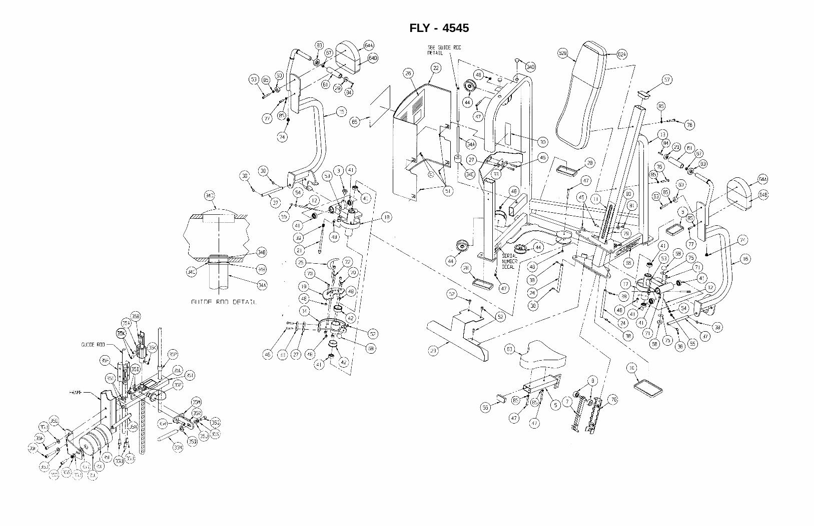
FLY - 4545
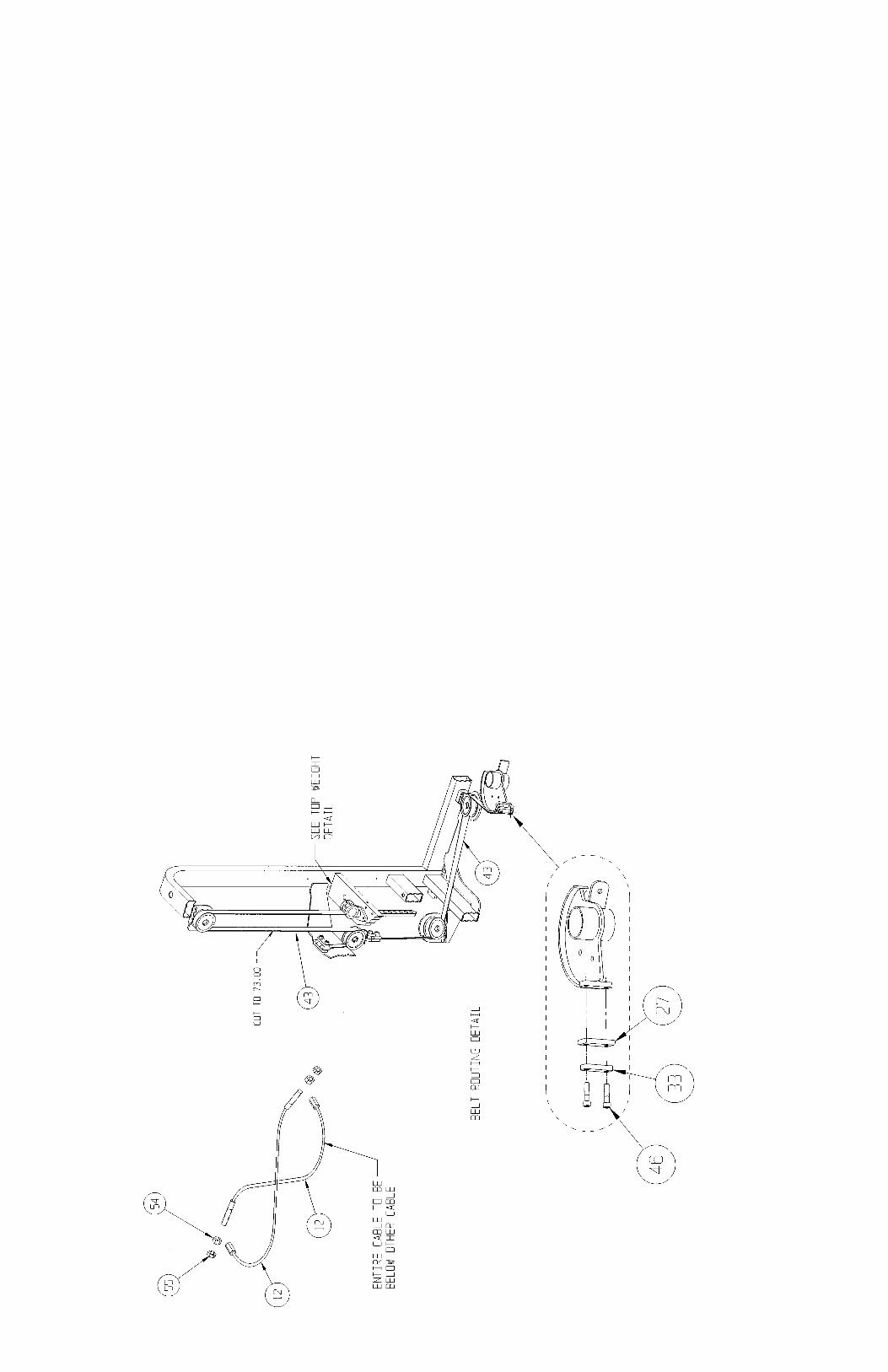
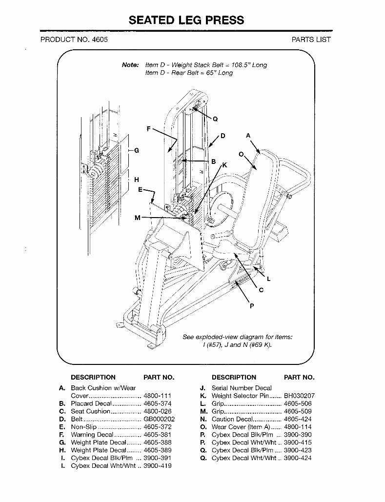
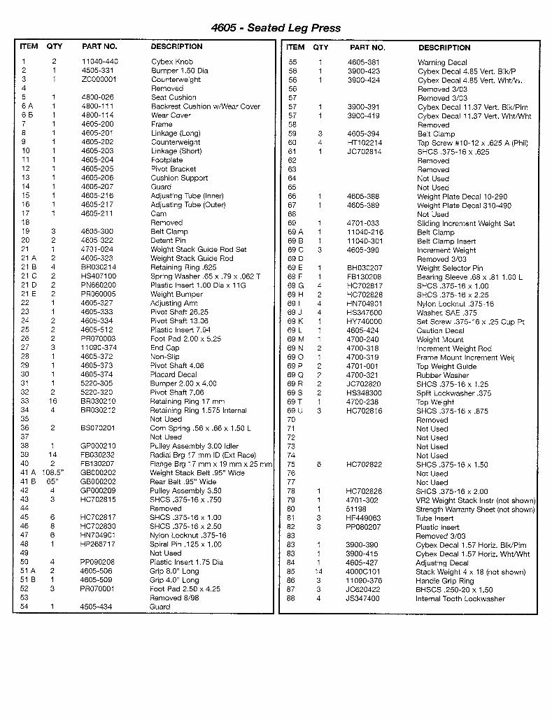
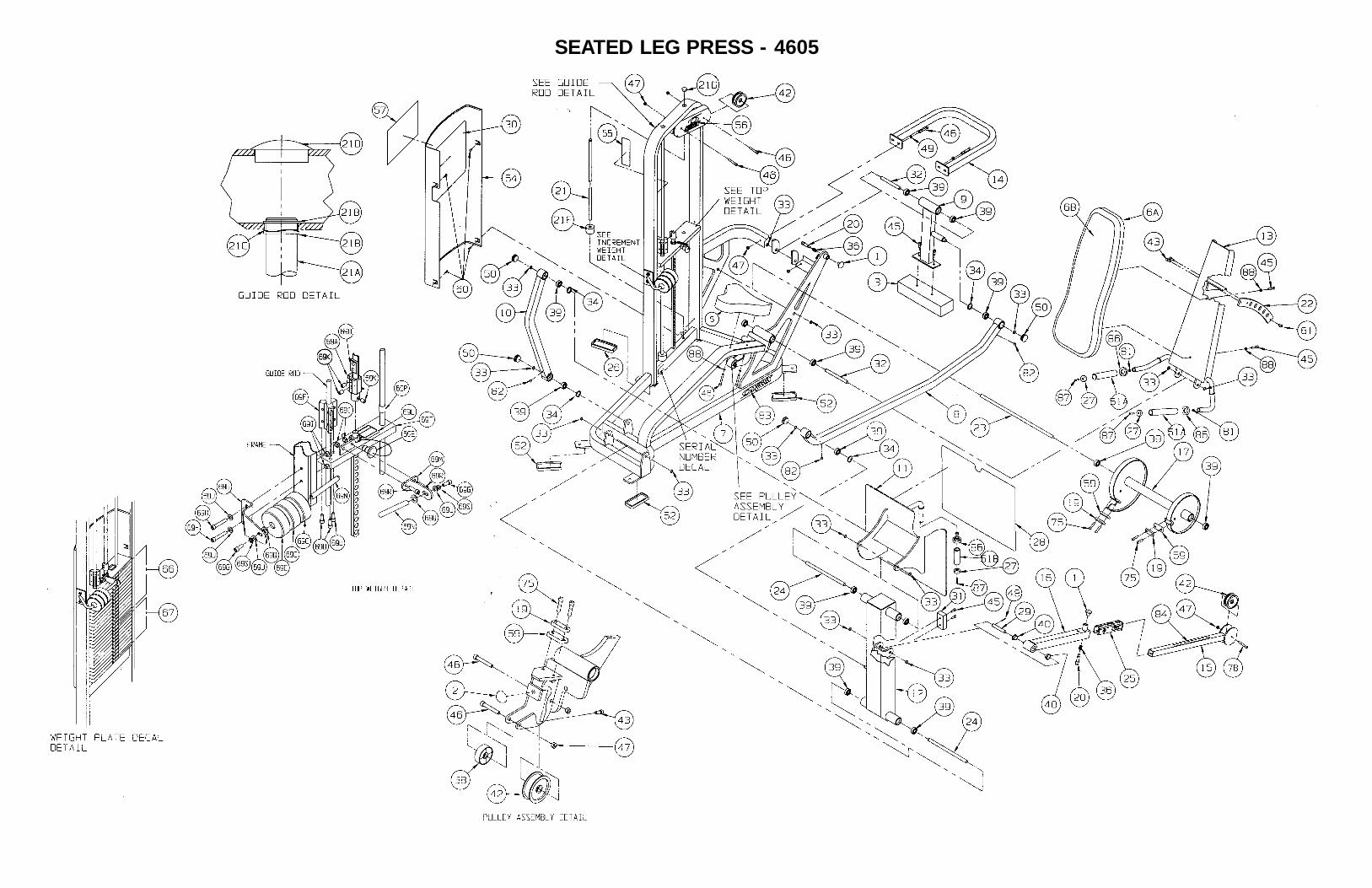
SEATED LEG PRESS - 4605
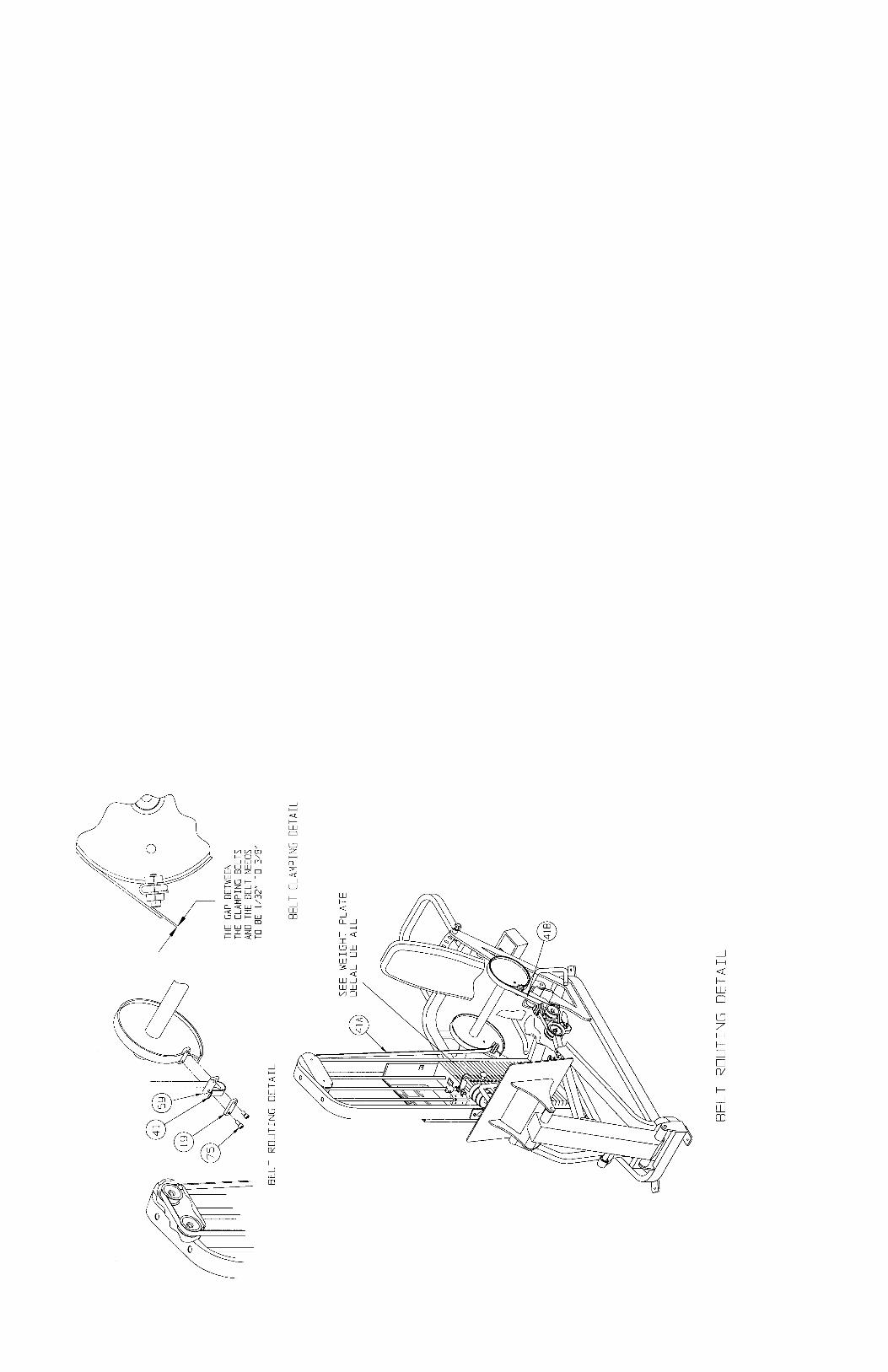
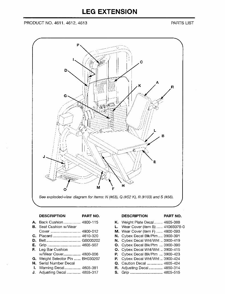
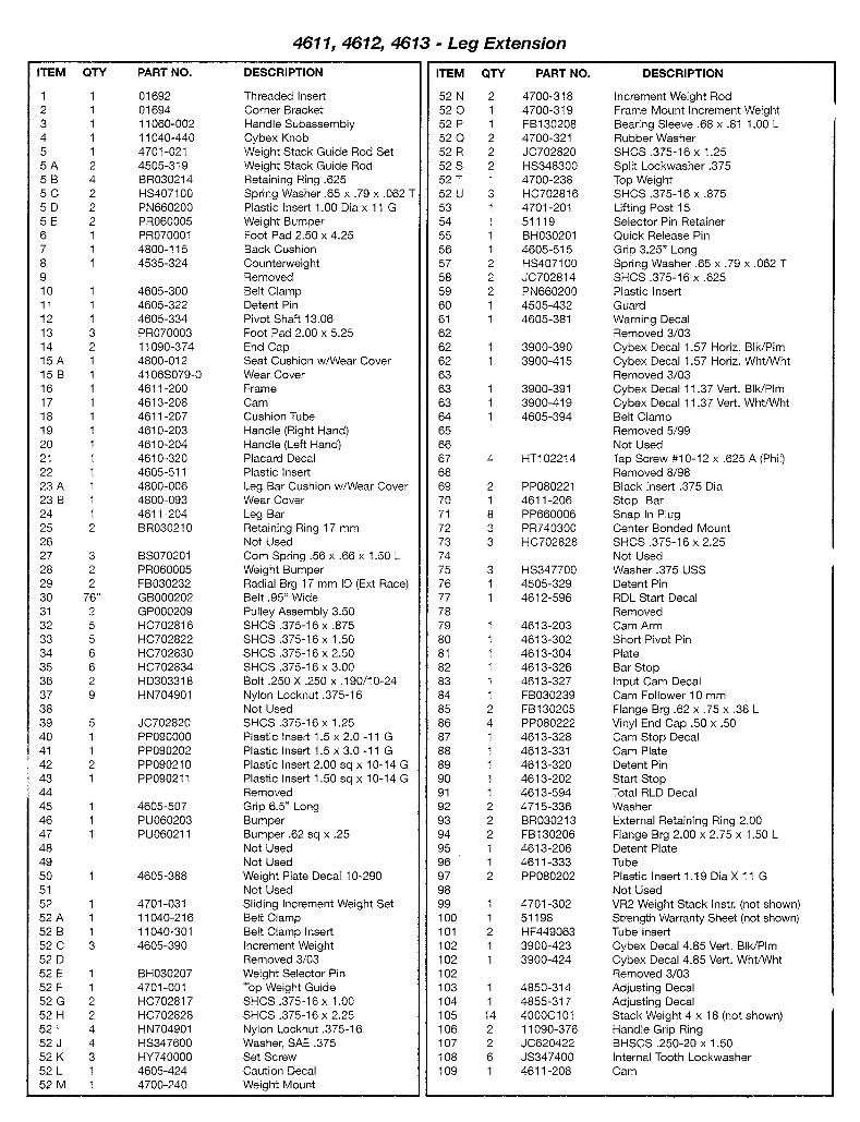
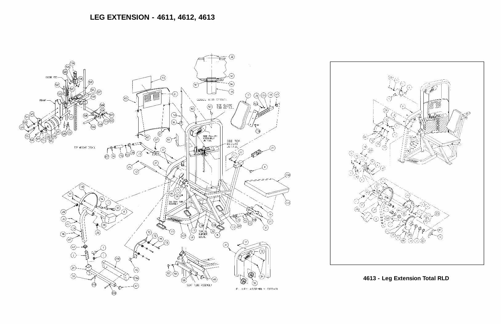
4613 - Leg Extension Total RLD
LEG EXTENSION - 4611, 4612, 4613
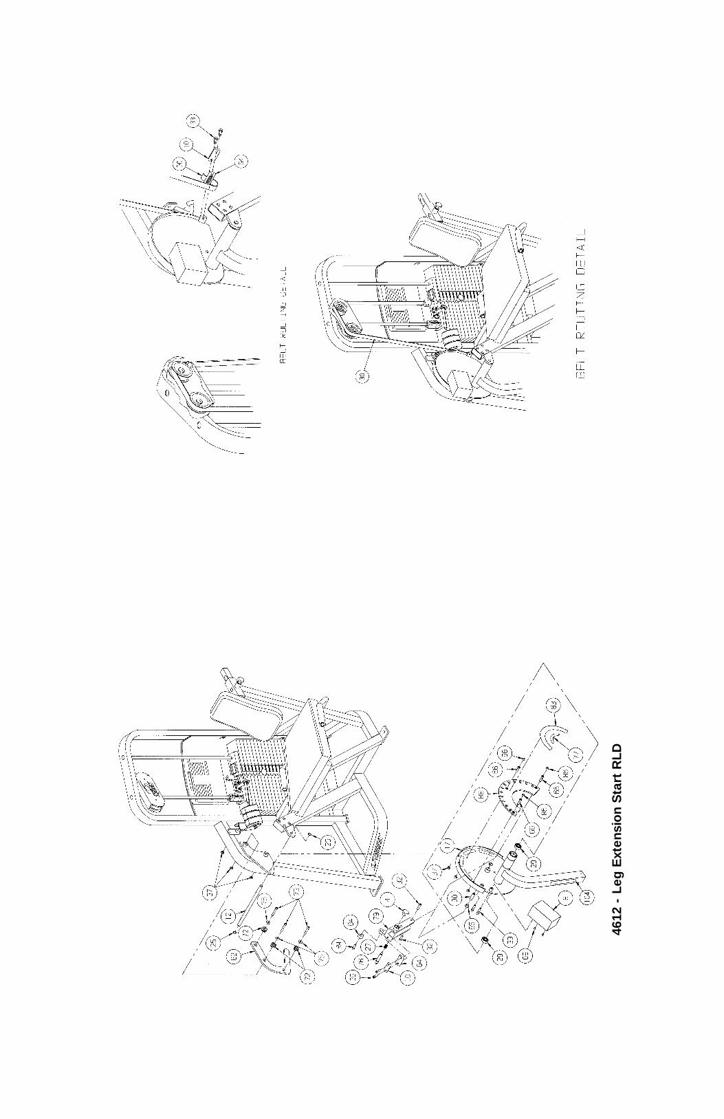
4612
- L
eg E
xten
sio
n S
tart
RLD
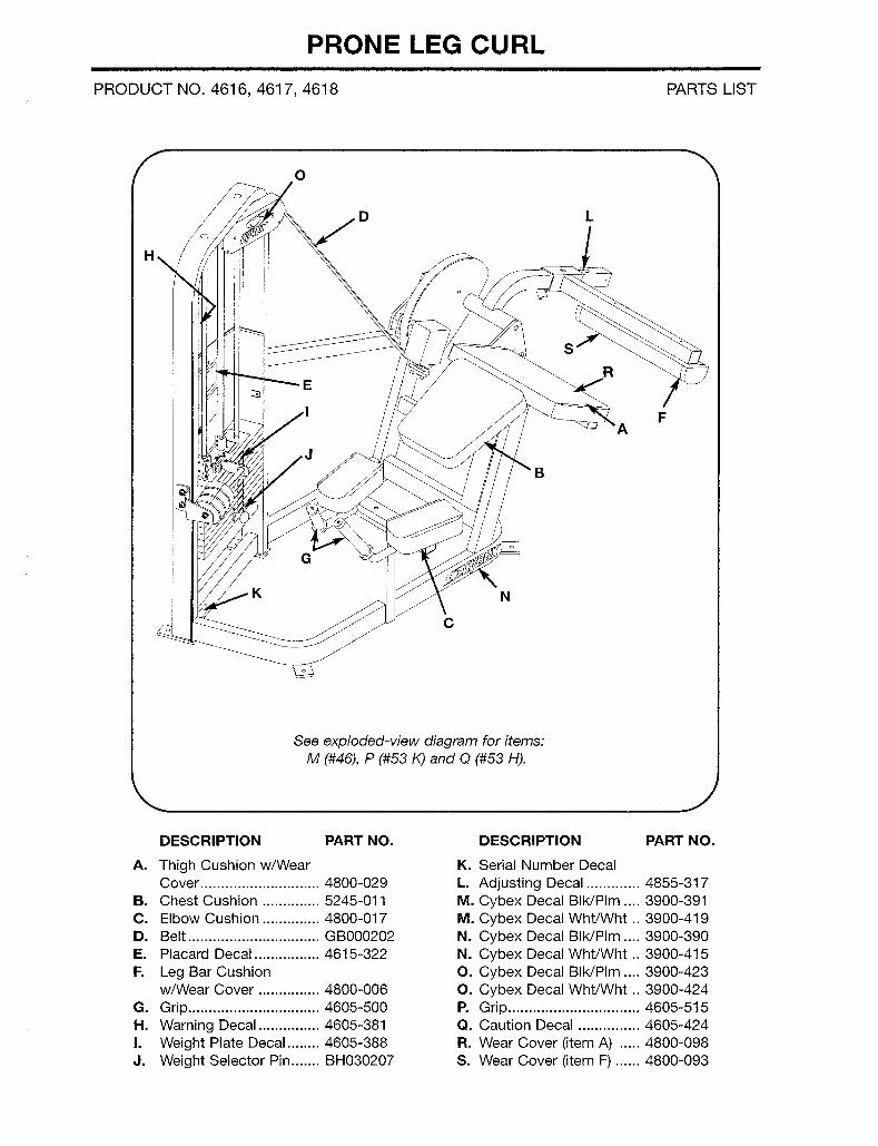
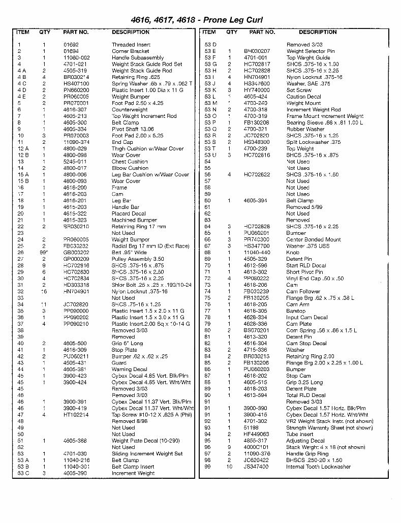
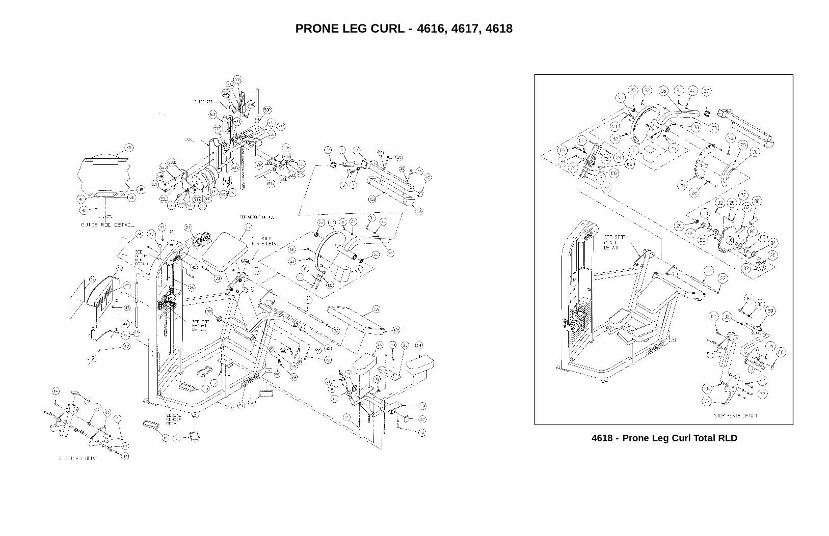
PRONE LEG CURL - 4616, 4617, 4618
4618 - Prone Leg Curl Total RLD
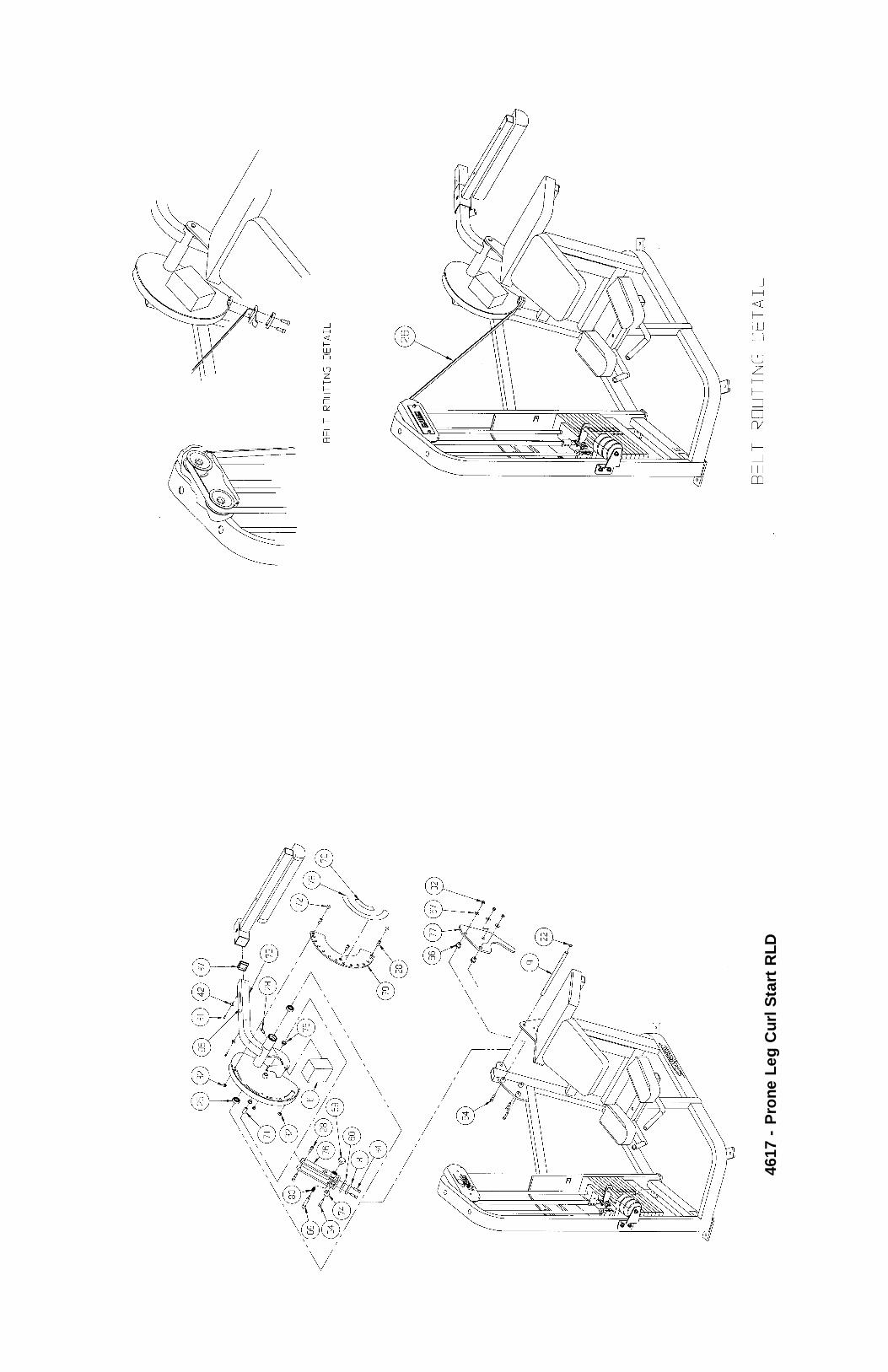
4617
- P
rone
Leg
Cur
l Sta
rt R
LD
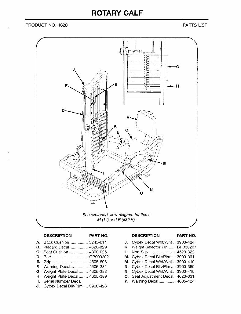
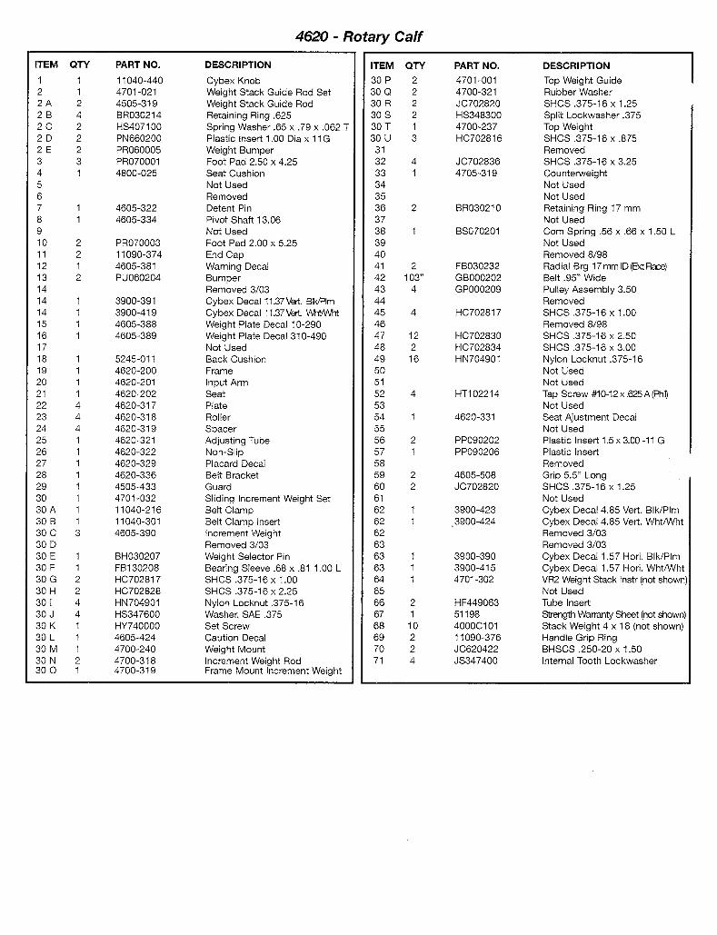
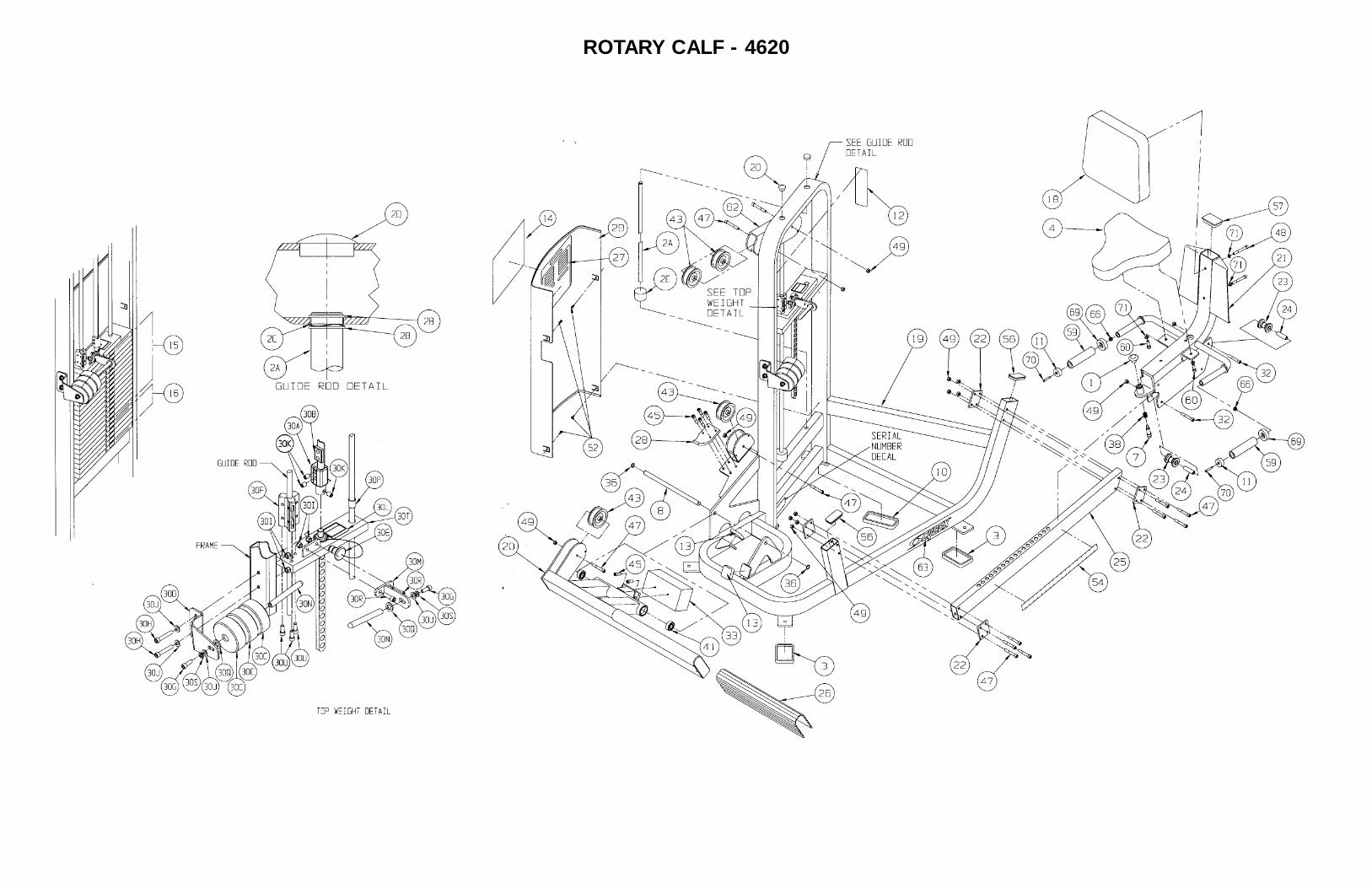
ROTARY CALF - 4620
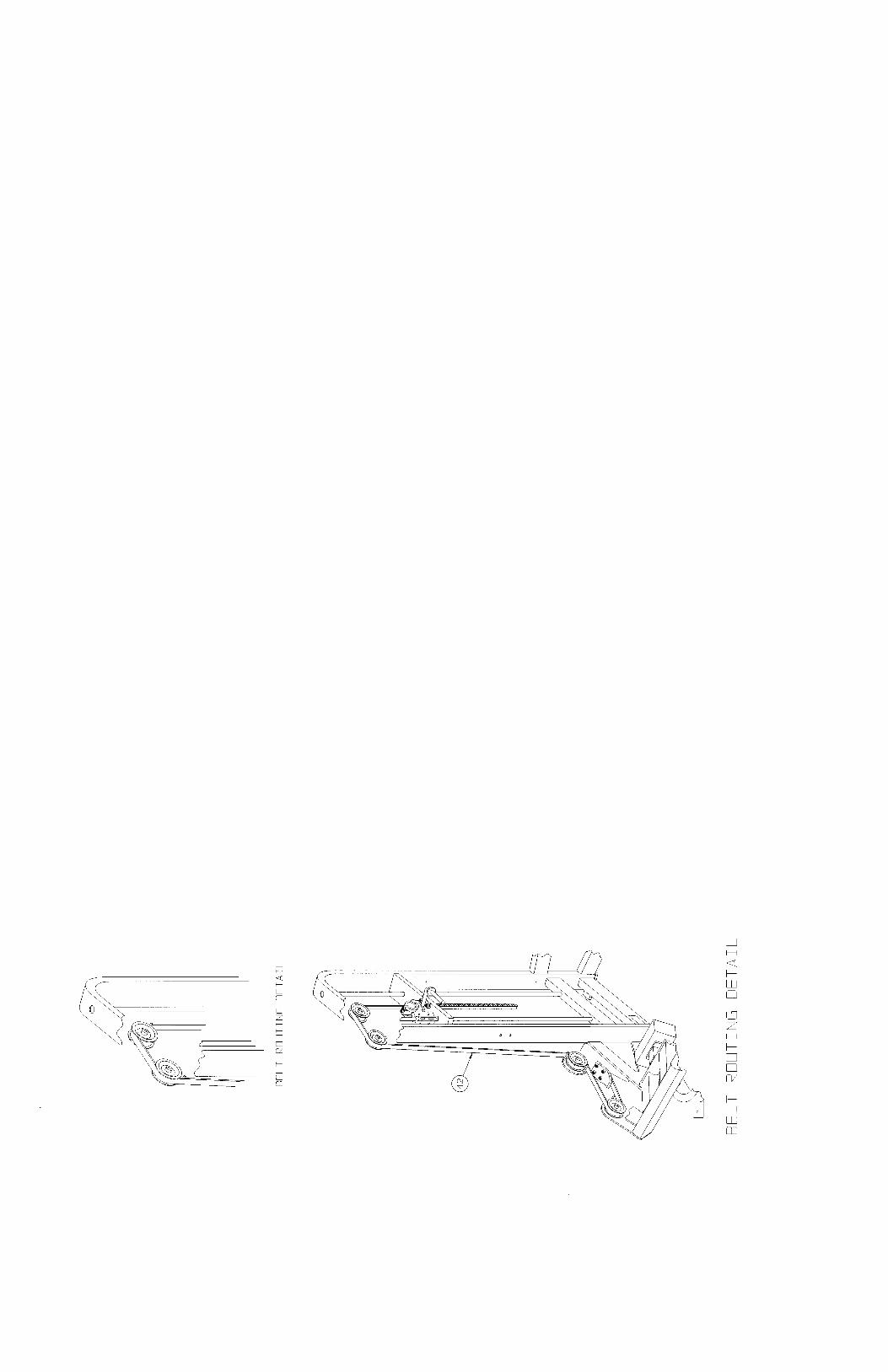
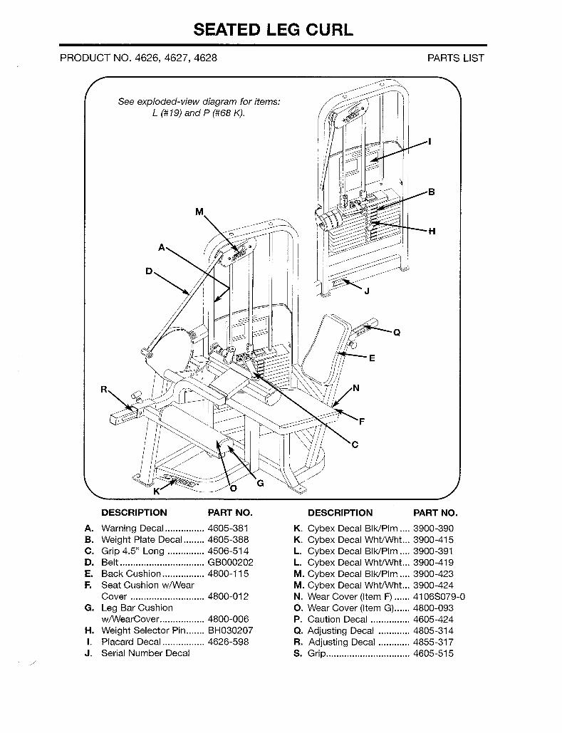
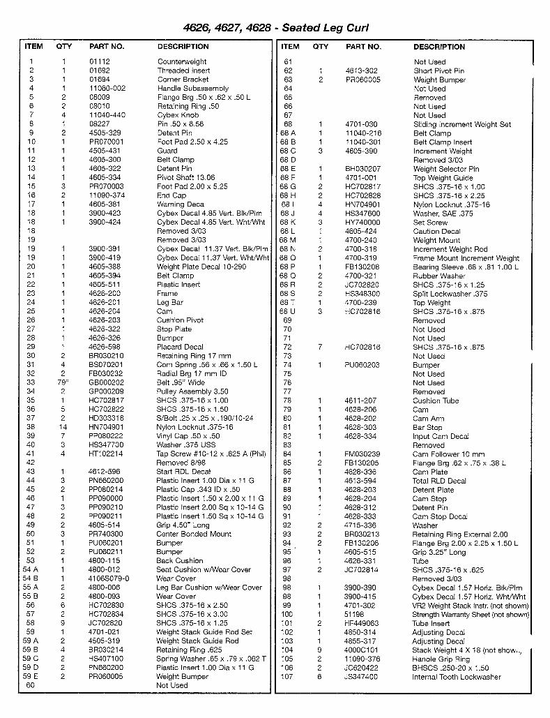
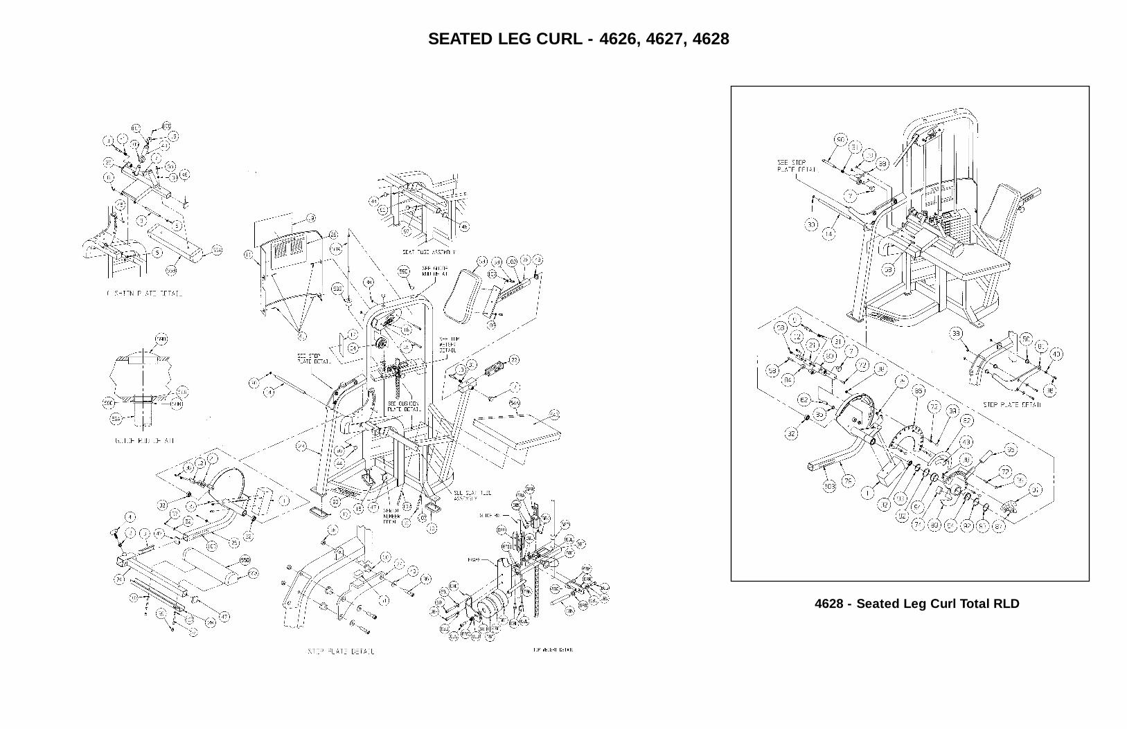
4628 - Seated Leg Curl Total RLD
SEATED LEG CURL - 4626, 4627, 4628
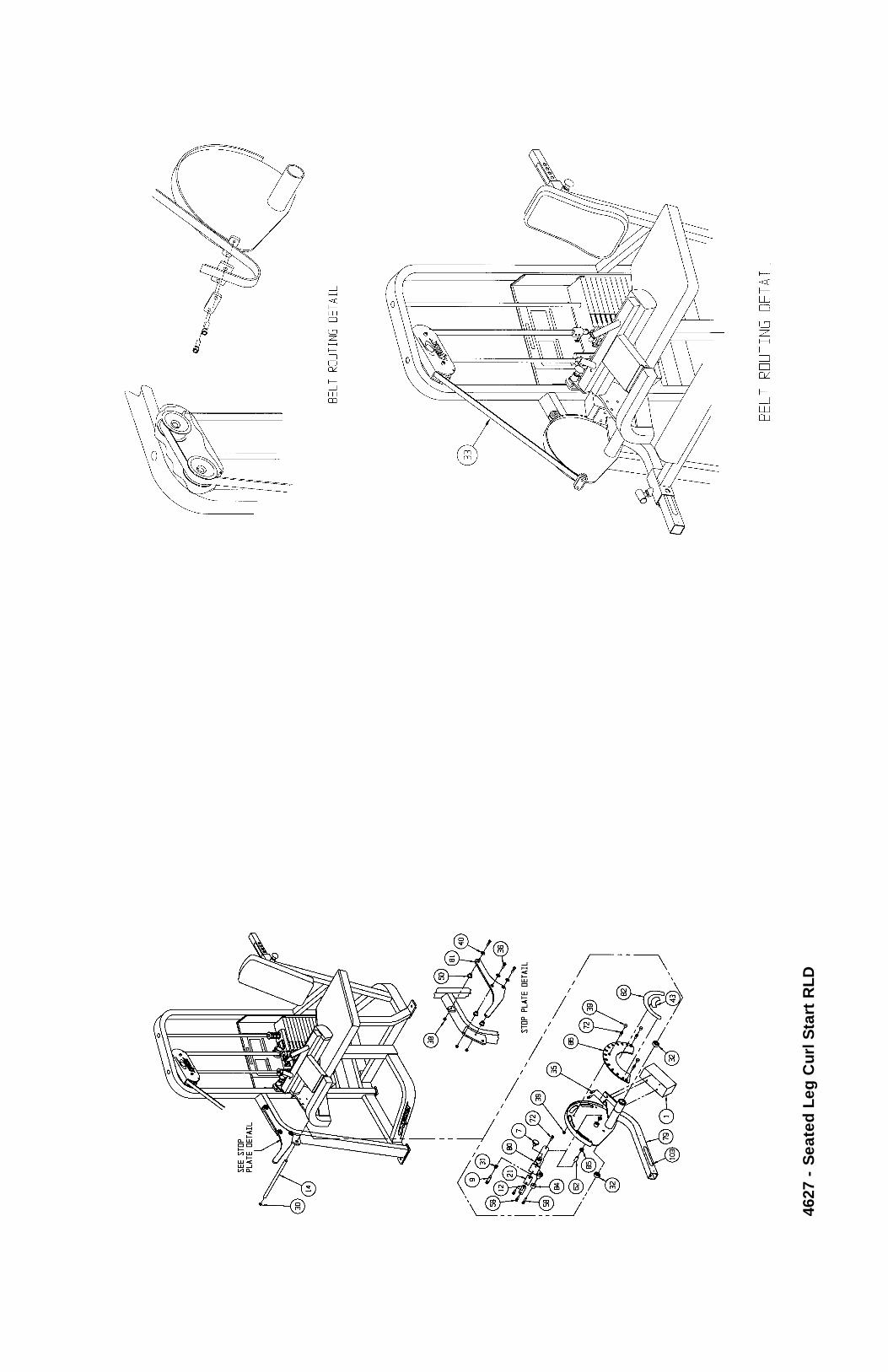
4627
- S
eate
d L
eg C
url S
tart
RLD
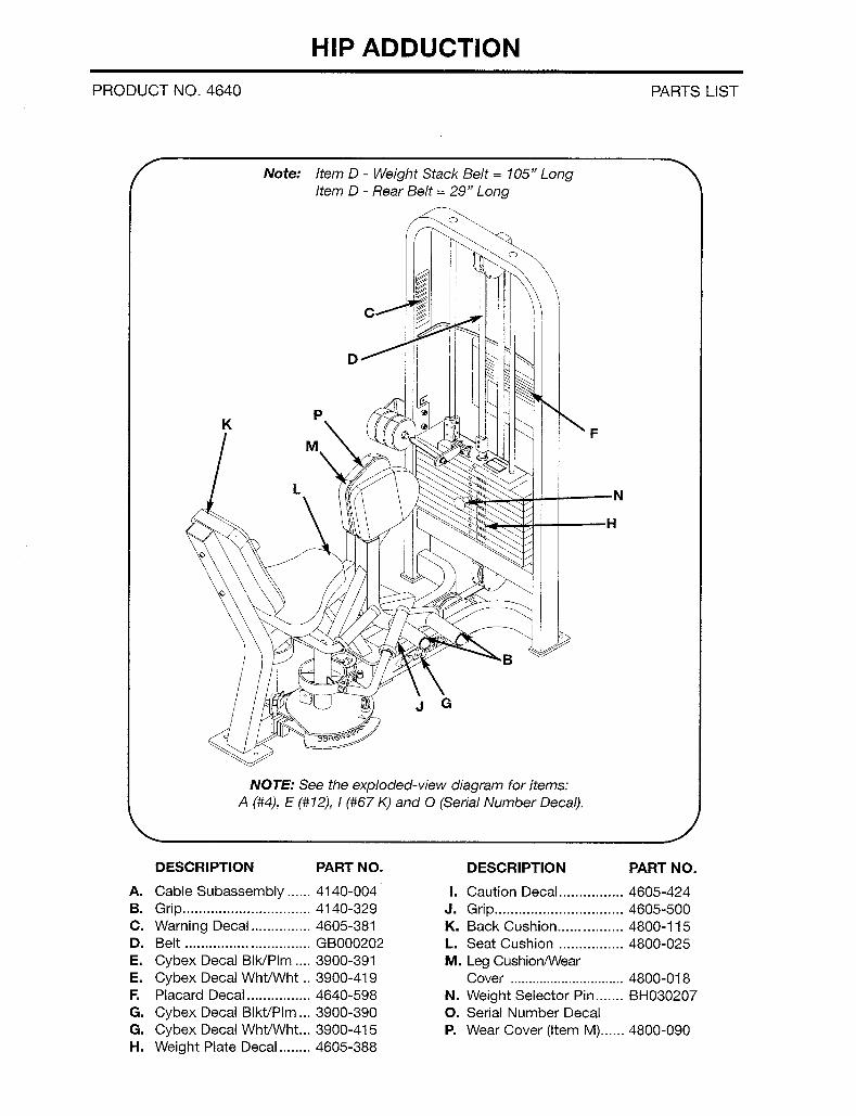
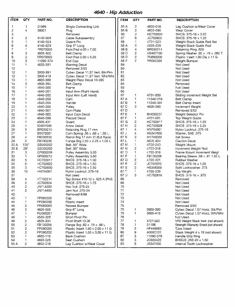

HIP ADDUCTION - 4640
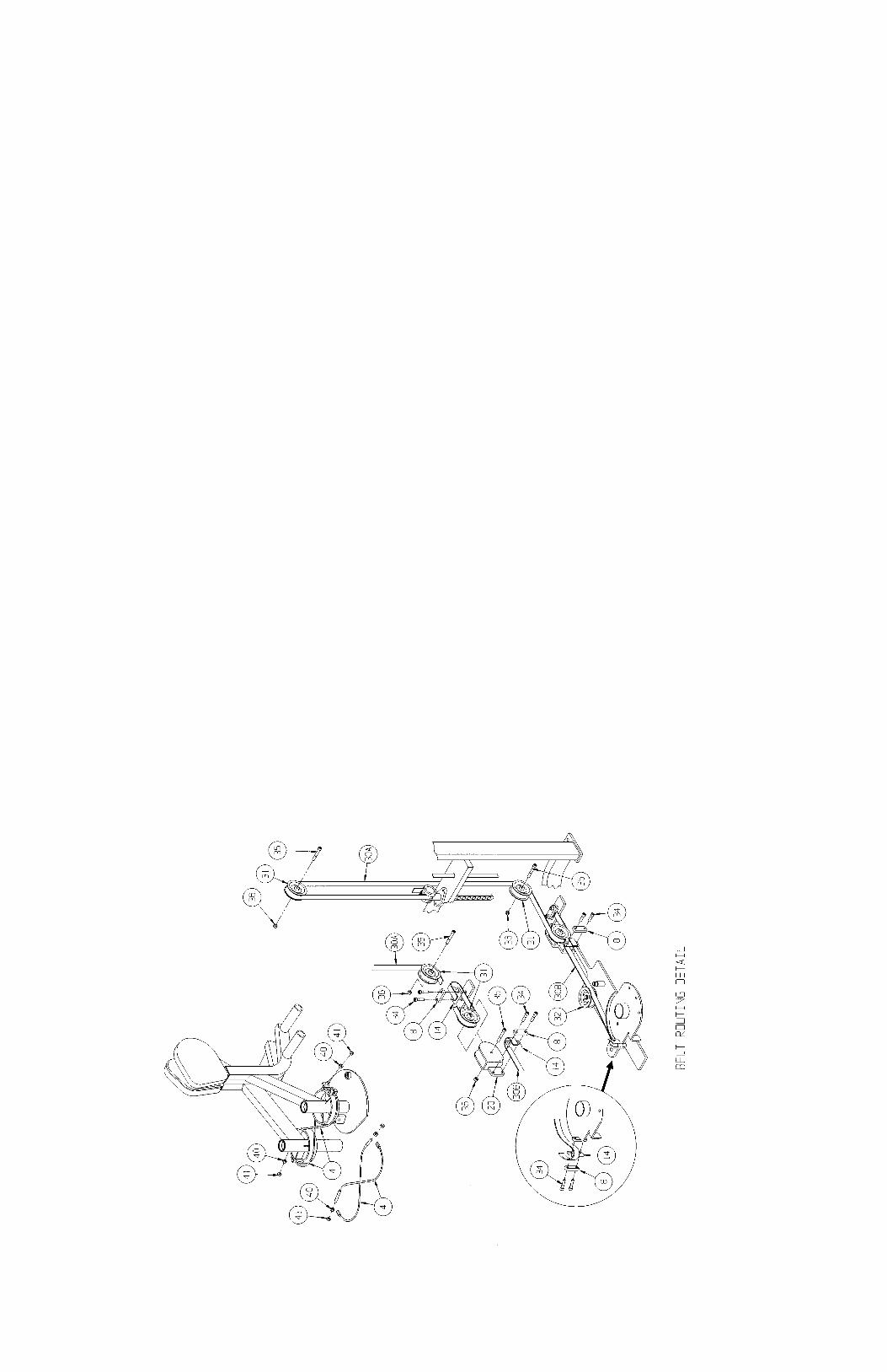
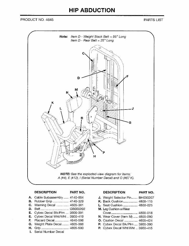
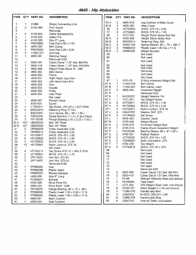
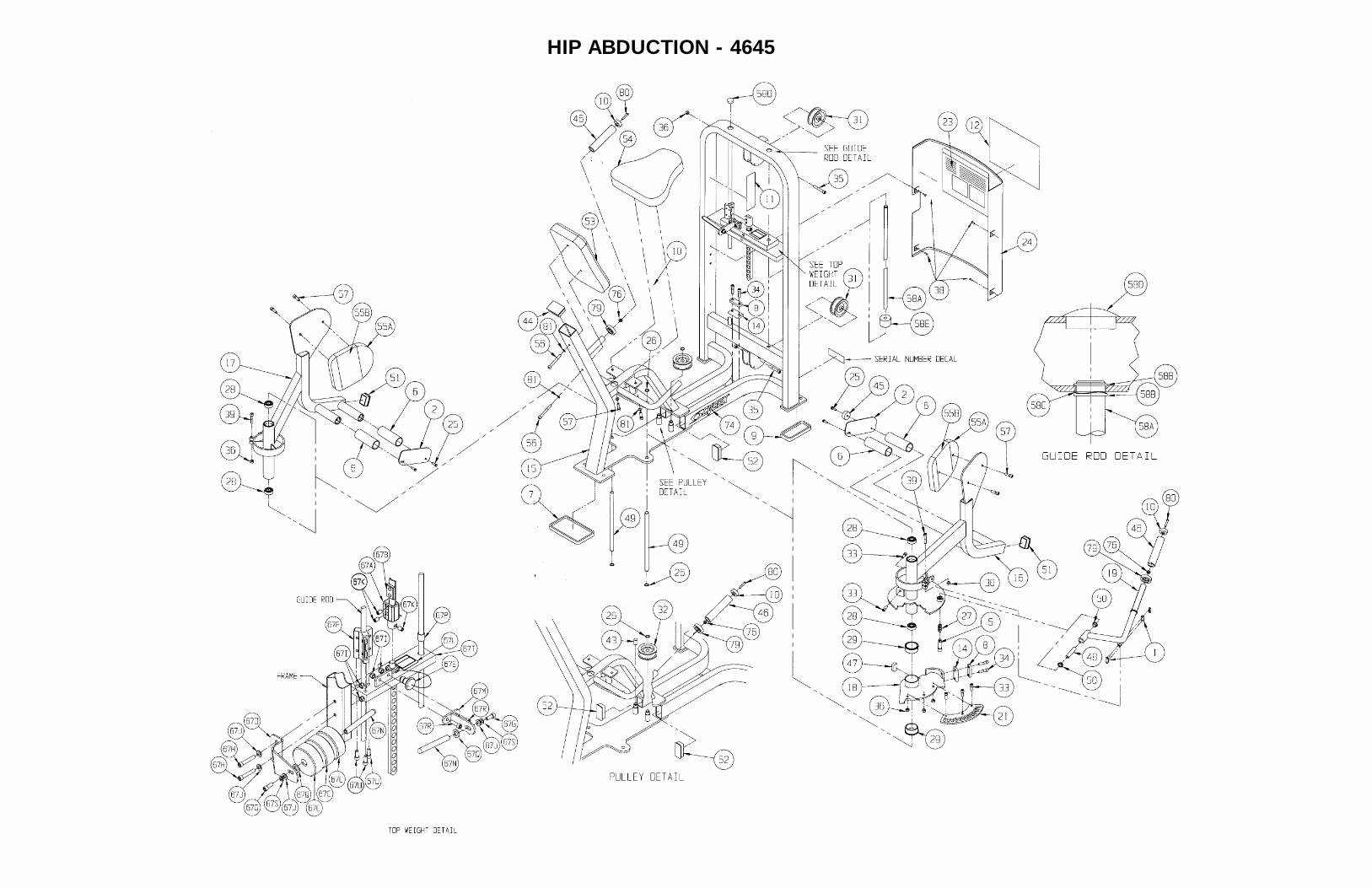
HIP ABDUCTION - 4645
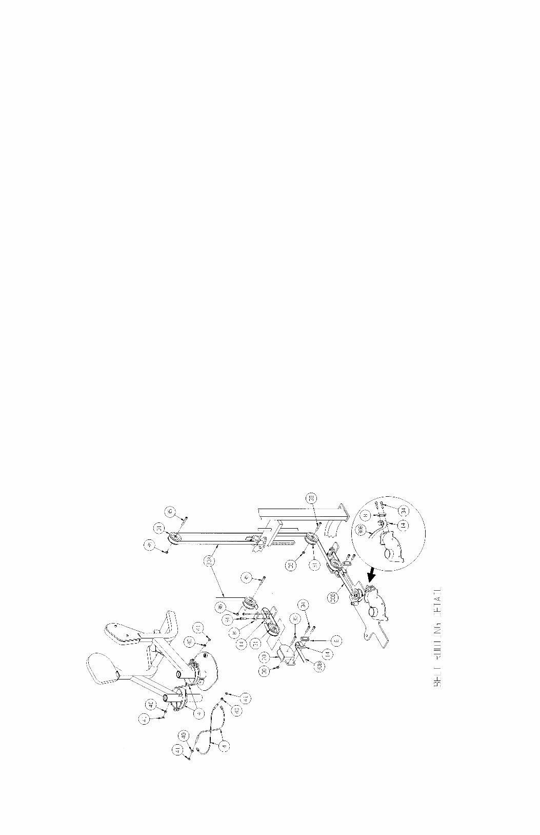

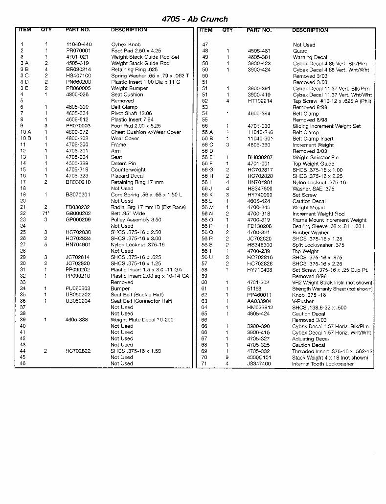
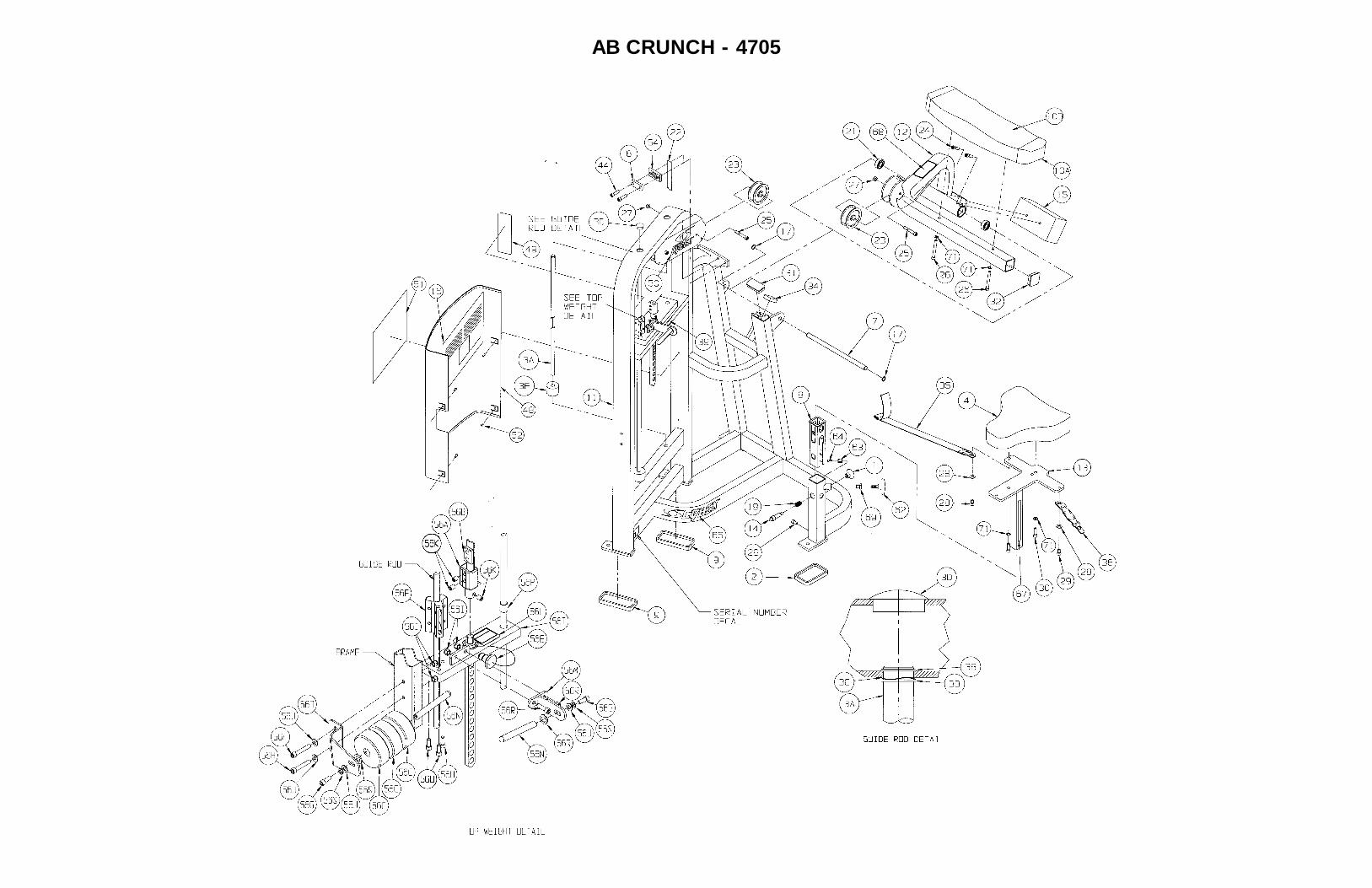
AB CRUNCH - 4705
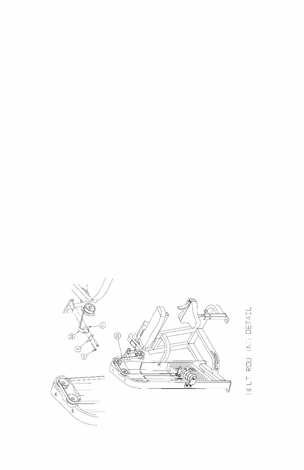
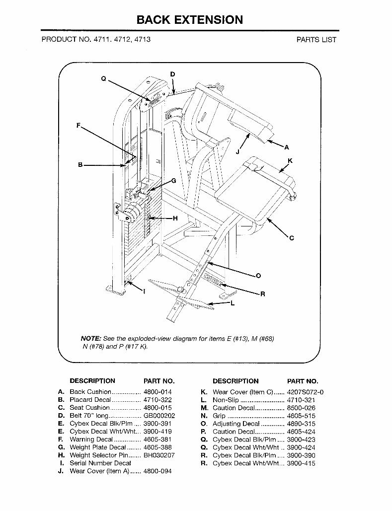
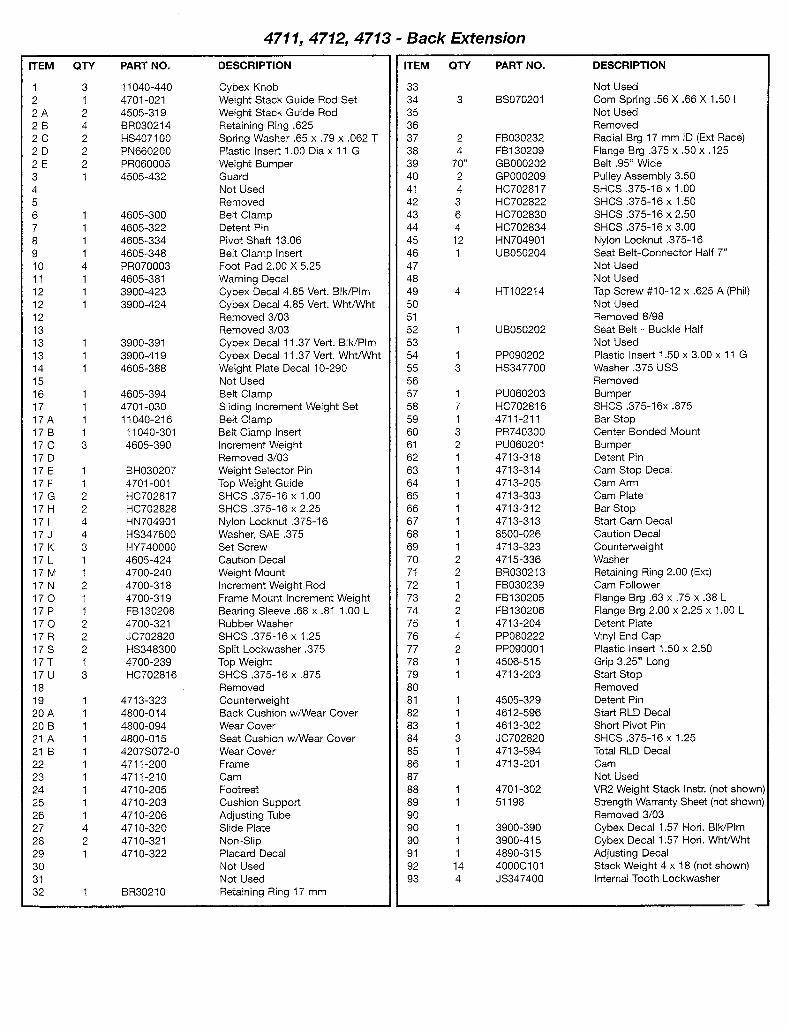
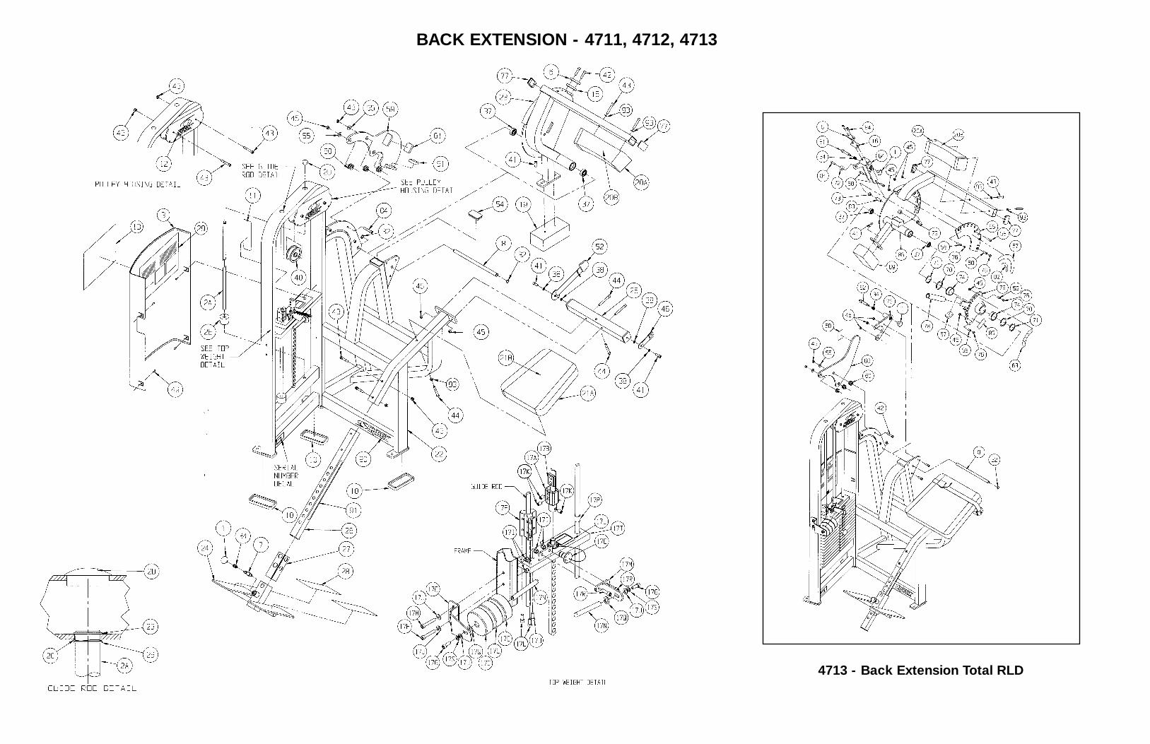
4713 - Back Extension Total RLD
BACK EXTENSION - 4711, 4712, 4713
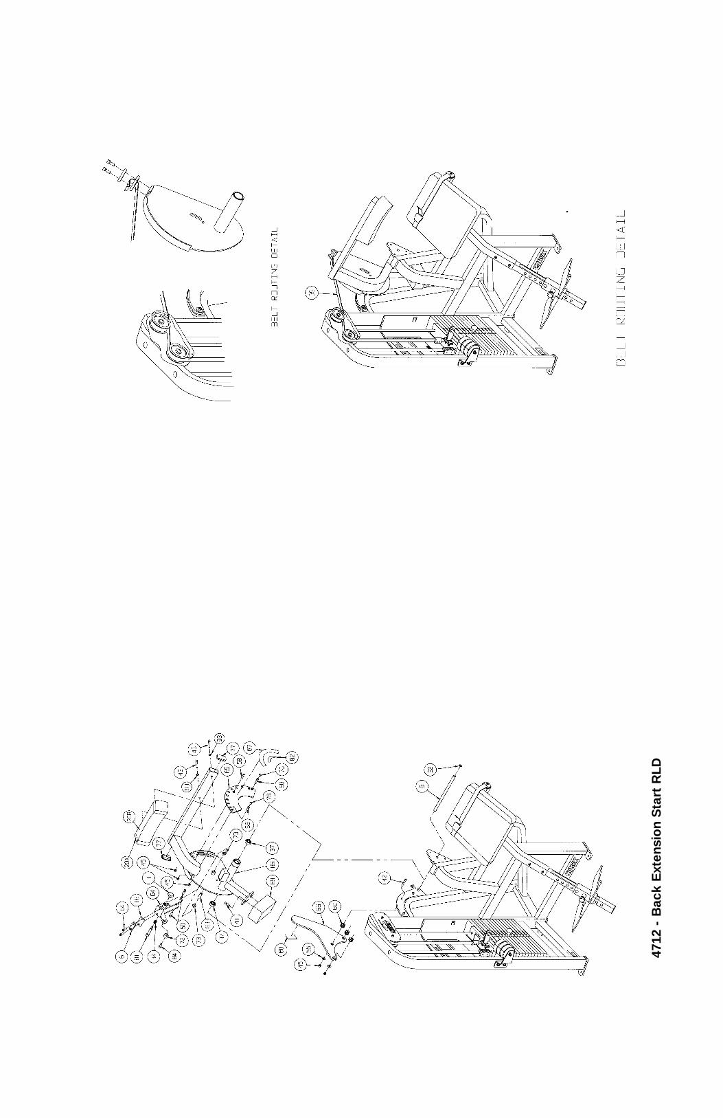
4712
- B
ack
Ext
ensi
on
Sta
rt R
LD
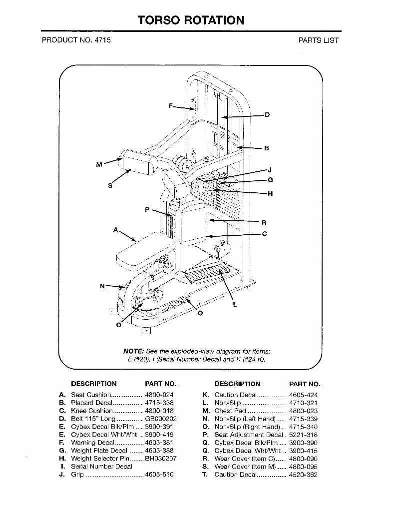
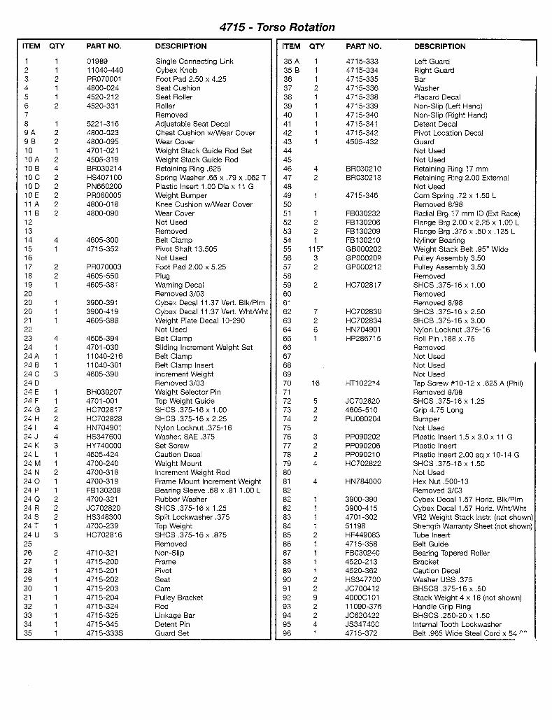
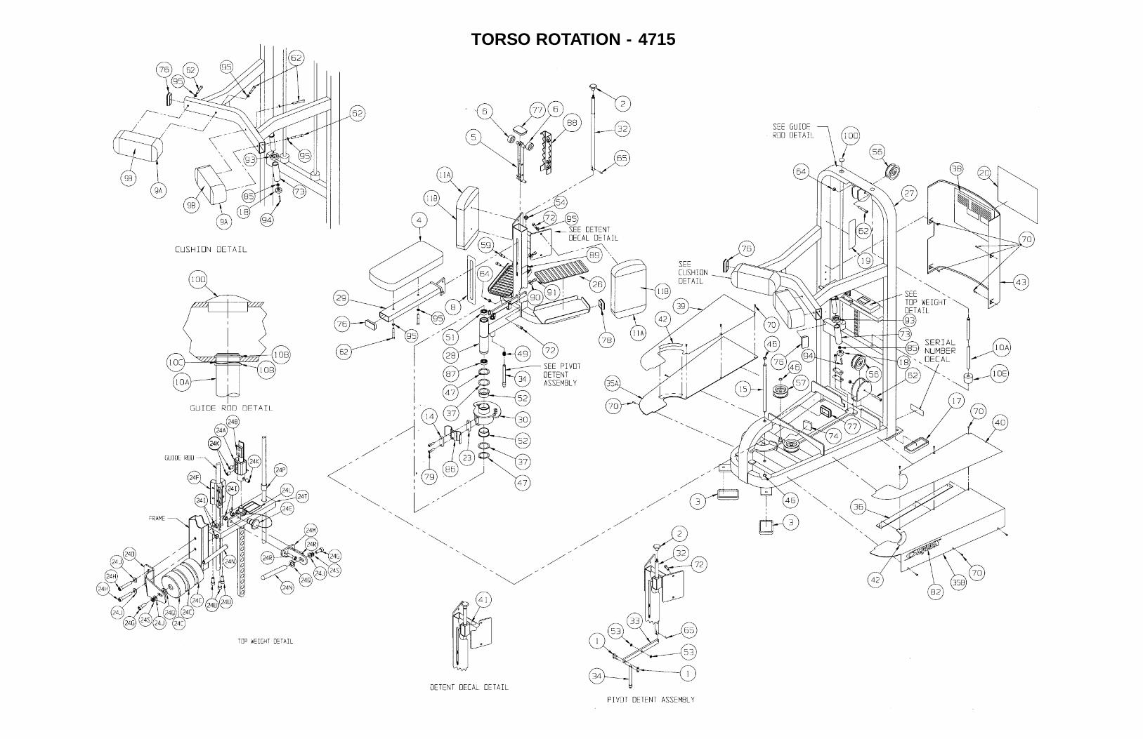
TORSO ROTATION - 4715
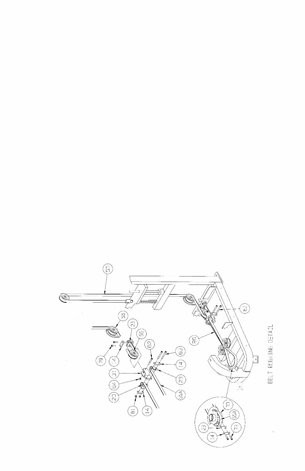


10 Trotter Drive Medway, MA 02053 • 508-533-4300 • FAX 508-533-5183 www.cybexinternational.com • [email protected] • [email protected]