CW6 PART 1
44
CW6: PART 1 TECHNICAL SPECIFICATION FOR THE EXTERNAL PROTECTION OF STEEL LINE PIPE AND FITTINGS USING FUSION BONDED POWDER AND ASSOCIATED COATING SYSTEMS PART1 - REQUIREMENTS FOR COATING MATERIALS AND METHODS OF TEST Jan. 1993 J229 ( Rev 08/98)
-
Upload
topnames62 -
Category
Documents
-
view
216 -
download
5
description
Cold Applied Wrapping Tapes
Transcript of CW6 PART 1

CW6: PART 1
TECHNICAL SPECIFICATION FOR
THE EXTERNAL PROTECTION OF STEEL LINE PIPEAND FITTINGS USING FUSION BONDED POWDERAND ASSOCIATED COATING SYSTEMSPART1 - REQUIREMENTS FOR COATINGMATERIALS AND METHODS OF TEST
Jan. 1993
J229 ( Rev 08/98)

.

CW6: Part 1
J229 ( Rev 08/98) - i -
CONTENTS
Page
FOREWORD v
BRIEF HISTORY vi
SECTION ONE - GENERAL REOUIREMENTS
1. SCOPE 1
2. REFERENCES 1
3. DEFINITIONS 2
4. COATING MATERIALS 2
4.1 Acceptable materials 2
4.2 Identification of materials 3
4.3 Production data sheets 3
4.4 Toxicity and handling 3
5. VARIANTS 3
SECTION TWO - BASIC PROPERTIES AND TESTS FOR POWDER AND CURED COATING
6. BASIC PROPERTIES OF THE POWDER 4
6.1 General 4
6.2 Infra-red scan 4
6.3 Gel time 4
6.4 Particle size analysis 4
6.5 Density 4
6.6 Moisture content 4
6.7 Thermal analysis 4
6.8 Stability 4
7. BASIC PROPERTIES OF THE DETACHED COATING FILM 4
7.1 General requirements 4
7.2 Micro-sectioning 4
7.3 Tensile strength 5
7.4 Elongation 5
7.5 Dielectric strength 5
CW6: Part 1
- ii - J229 ( Rev 08/98)
Page
7.6 Water permeability 5
7.7 Water absorption 5
8. BASIC PROPERTIES OF THE CURED APPLIED COATING 5
8.1 Physical performance test requirements 5
8.2 Environmental test requirements 6
8.3 Thermal stability test 7
9. QUALITY CONTROL REQUIREMENTS 7
10. COMPLIANCE 7
SECTION THREE - BASIC PROPERTIES AND TESTS OF MULTI-COMPONENT LIQUIDCOATING MATERIALS AND CURED COATING
11. BASIC PROPERTIES OF UNMIXED COATING MATERIALS 8
11.1 General 8
11.2 Total non-volatile content 8
11.3 Viscosity 8
11.4 Relative density 8
11.5 Mixing ratio 8
11.6 Potlife 8
11.7 Flash point 8
11.8 Stability 8
12. BASIC PROPERTIES OF DETACHED COATING FILM 8
12.1 General requirements 8
12.2 Micro sectioning 9
12.3 Tensile strength 9
12.4 Elongation 9
12.5 Dielectric strength 9
12.6 Water permeability 9
12.7 Water absorption 9
13. BASIC PROPERTIES OF CURED APPLIED COATING 9
13.1 Physical performance test requirements 9
13.2 Environmental test requirements 10
13.3 Thermal stability test 11
14. QUALITY CONTROL REQUIREMENTS 11

CW6: Part 1
J229 ( Rev 08/98) - iii -
Page
15. COMPLIANCE 11
APPENDICES
A METHODS FOR THE EVALUATION OF THE THERMAL CHARACTERISTICS OF POWDER AND CURED COATING 13
B FLEXIBILITY TEST 23
C HOLIDAY DETECTION OF COATINGS 26
D EVALUATION OF RESISTANCE TO IMPACT 27
E EVALUATION OF RESISTANCE TO WATER IMMERSION 30
F EVALUATION OF RESISTANCE TO CATHODIC DISBONDING 32
G STRAIN/POLARIZATION TEST 36

CW6: Part 1
- iv - J229 ( Rev 08/98)
CW6: Part 1
J229 ( Rev 08/98) - v -
FOREWORD
This specification has been adopted by Transco and is an editorial revision of the former British Gas TransCospecification GBE/CW6 Part 1. It reflects the identity and organizational structure of Transco - a part of BGplc.
This Transco specification has been approved for use throughout Transco.
Comments and queries regarding the technical content of this Transco specification should be directed to:
Lead EngineerTranscoNorgas HousePO Box 1GBKillingworthNewcastle upon TyneNE99 1GB
Further copies of this Transco specification can be obtained from Dataform Print Management using the printrequisition form G004 quoting the Form Number of this Transco engineering document (not the designation)and your cost code.
Transco engineering documents are revised, when necessary, by the issue of new editions. Users shouldensure that they are in possession of the latest edition by referring to the Transco Register of EngineeringDocuments available on the Transco Information Library.
Compliance with this engineering document does not confer immunity from prosecution for breach of statutoryor other legal obligations.
Contractors and other users external to Transco should direct their requests for further copies of Transcoengineering documents to the department or group responsible for the initial issue of their contractdocumentation.
DISCLAIMER
This engineering document is provided for use by Transco and such of its contractors as are obliged by the termsof their contracts to comply with this engineering document. Where this engineering document is used by anyother party, it is the responsibility of that party to ensure that the engineering document is correctly applied.

CW6: Part 1
- vi - J229 ( Rev 08/98)
BRIEF HISTORY
First published as BGC/PS/CW6:Part 1Re-issued as GBE/CW6:Part 1
January 1985January 1993
© BG plc 1992
This Transco specification is copyright and must not be reproduced in whole or in part by any means withoutthe approval in writing of BG plc.
CW6: Part 1
J229 ( Rev 08/98) - 1 -
TECHNICAL SPECIFICATION FOR
THE EXTERNAL PROTECTION OF STEEL LINE PIPE ANDFITTINGS USING FUSION BONDED POWDER ANDASSOCIATED COATING SYSTEMSPART 1 - REQUIREMENTS FOR COATING MATERIALS ANDMETHODS OF TEST
SECTION ONE - GENERAL REQUIREMENTS
1. SCOPEThis Transco Technical Specification* CW6 specifies materials for use as anti-corrosion coatings on steel linepipe and fittings. It deals specifically with the properties and performance tests to establish suitability for usewith Part 2 of this specification, which deals with factory applied coatings, and for use with CW5 for certainfield applied coatings.
Section One of this specification covers general requirements. Section Two covers fusion bonded powder andSection Three covers multi-component liquid coating materials.
* Hereinafter referred to as 'this specification'.
2. REFERENCESThis specification makes reference to the documents listed below. Unless otherwise specified the latesteditions of these documents, including all addenda and revisions, shall apply.
Statutes and Regulations
- Classification, Packaging and Labelling of Dangerous SubstancesRegulations 1984
- Control Of Substances Hazardous to Health (COSHH) Regulations
- The Health and Safety at Work etc. Act 1974
British Standards
BS 1387 - Specification for screwed and socketed steel tubes and tubulars and forplain end steel tubes suitable for welding or for screwing to BS 21pipe threads
BS 2015 - Glossary of paint terms
BS 3900 - Methods of test for paints:Part B2: Determination of volatile matter and non-volatile matterPart F2: Determination of resistance to humidity (cyclic condensation)Part F3: Resistance to artificial weathering (enclosed carbon arc)Part F4: Resistance to continuous salt spray
BS 7079 - Preparation of steel substrates before application of paints and relatedproducts
CW6: Part 1
- 2 - J229 ( Rev 08/98)
American Society for Testing and Materials
ASTM G14-77 - Test for impact resistance of pipeline coatings - (Falling weight test)
Transco specifications
CM2 - Specification for internal coating materials for steel line pipe andfittings
CW5 - Code of practice for the selection and application of field appliedexternal pipework coatings
CW6 - Technical specification for the external protection of steel line pipeand fittings using fusion bonded powder and associated coatingsystems:Part 2 - Factory applied coatings.
3. DEFINITIONSFor the purposes of this Specification the following definitions shall apply:
Transco : Transco - a part of BG plc.
Transco representative: the person appointed from time to time by Transco and notified in writing to theContractor to act as Transco representative for the purposes of the Contract.
Contractor: the person, firm or company with whom Transco enters into a contract to which thisspecification applies, including the Contractor's personal representatives, successors and permitted assigns.
Manufacturer: the producer of the coating material being offered for test or his appointed agents or assigns.
4. COATING MATERIALS
4.1 Acceptable materials
4.1.1 Coating systemsOnly coating systems conforming to this specification shall be considered for application in accordance withCW6: Part 2. Coating systems may include the use of primer or chemical pretreatment of the steel surface toenhance adhesion. In such cases, the pretreatment and coating material shall be clearly specified as acombined system.
Where recycled material is used, the ratio of recycled to virgin material shall be stated. Any coating systemmade up with a recycled material mix shall meet the requirements of this specification.
Fusion bonded powder shall also meet the requirements of Part 1 of this specification without the use ofchemical pretreatment.
4.1.2 Compliance with this specificationThe Contractor shall be responsible for ensuring that all coating materials and equipment comply with all ofthe provisions specified in this specification and Transco may make any investigation necessary, by way oftesting, batch sampling and manufacturing inspection, to satisfy itself of compliance by the Contractor.
4.1.3 Application of this SpecificationIt is intended that this specification be used to encourage and stimulate the development of progressivelybetter external pipeline coatings. Thus, where certain minimum performance values are stated and shouldfuture coating material test submissions yield better performance than the specified requirements then, aftereconomic evaluation, these new values may be adopted as the minimum requirements and the specificationwould be up-graded accordingly.

CW6: Part 1
J229 ( Rev 08/98) - 3 -
4.1.4 Supply of dataThe Contractor shall furnish, on request and in confidence, such details as may be required by Transco, whichmay include formulations, typical physical constants, manufacturing tolerances and application dataassociated with the coating materials being used. Transco also reserve the right of direct communication withthe Manufacturer should the need arise.
Any change of formulation, or manufacturing supply route, of a material may be proposed for consideration asa variant by Transco and supply of the modified material shall not be implemented until such time as therevised procedure qualification trials have been completed.
4.2 Identification of materialsAll materials supplied for coating operations shall be suitably marked giving the following information:
a) Manufacturer's name, initials or identification mark.
b) Name of material.
c) Batch number.
d) Date of manufacture and 'use by' date.
e) Storage temperature limits.
f) Safety data sheet (included with delivery).
Containers and any associated packaging shall, where appropriate, be marked in accordance with theClassification. Packaging and Labelling of Dangerous Substances Regulations 1984.
The Contractor shall require the Manufacturer to supply certificates confirming that tests specified in thisspecification have been carried out on the batches supplied and that the materials meet the specifiedrequirements. These certificates shall be made available for examination by Transco on request.
4.3 Production data sheetsThe Contractor shall be responsible for obtaining data sheets from the Manufacturer which shall includevalues for all the basic properties of the material as specified in the 'Basic properties' clause in the appropriateSection of this specification.
4.4 Toxicity and handlingAny hazard including toxic, corrosive risks and fire risks, associated with coating materials offered for use tomeet the requirements of this specification shall be specified by the Manufacturer, together with hisrecommendations for safe handling in accordance with the requirements of the Health and Safety at Work etc.Act 1974 and the COSHH Regulations.
Containers and associated packages shall be marked with their weights and, where appropriate, be providedwith handling points, e.g. handles or hand holes.
5. VARIANTSA contractor shall only propose variants to this specification where the text indicates that variants would beconsidered by Transco.

CW6: Part 1
- 4 - J229 ( Rev 08/98)
SECTION TWO - BASIC PROPERTIES AND TESTS FOR POWDER AND CURED COATING
6. BASIC PROPERTIES OF THE POWDER
6.1 GeneralThe Contractor shall obtain from the Manufacturer specified and qualified ranges of values for all propertieslisted in 6.2 to 6.8 inclusive that will ensure an acceptable coating. The frequency of testing shall be inaccordance with 9.2.
6.2 Infra-red scanAn infra-red spectrogram, preferably made by using a standard potassium bromide (KBr) disc, shall beobtained from a typical batch of the powder. This shall subsequently be used for comparison with typespectrograms.
6.3 Gel timeA hot plate technique shall be used to obtain values of the gel time, and the values obtained of each batchshall be used for comparison with values originally quoted.
6.4 Particle size analysisThe particle size distribution of the powder shall be the optimum to suit the particular method of application.
Particle size range shall be quoted in the production data sheet. Each batch shall be checked for conformitywith the values originally quoted.
6.5 DensityThe density of the powder shall be measured for all batches produced, and the values shall conform with thevalue originally specified.
6.6 Moisture contentThe moisture content of the powder shall be less than 0.5% by weight and shall be checked for every batch.
6.7 Thermal analysisThermal analysis data for each batch shall be made available showing, by use of a Differential ScanningCalorimeter (DSC), the glass transition of the raw powder and also the enthalpy of the curing powder. Theglass transition temperature of the fully cured powder shall also be quoted. The reference curve shall beprovided as part of the production data sheet (see 4.3). The limiting values of H∆ , Tg1 and Tg2
(see Appendix A) shall be identified by the Manufacturer.
6.8 Stability
After ageing for 120 days at 25 ± 1 0 C in a sealed container, the powder shall not exhibit any significantchange from the properties identified in 6.2 to 6.7 inclusive.
7. BASIC PROPERTIES OF THE DETACHED COATING FILM
7.1 General requirementsThe Contractor shall ensure that the tests specified in 7.2 to 7.7 inclusive are carried out by the Manufacturerin accordance with 9.4. The tests shall be carried out on detached coating samples, m400µ to m450µ thick,
which have been prepared by application on to polished steel plates, 6 mm thick, previously coated withpolytetrafluoroethylene (PTFE).
7.2 Micro sectioningA cross-section of the cured film shall be examined at a magnification of X100 and shall be seen to behomogeneous and essentially free of voids, foaming or other defects.

CW6: Part 1
J229 ( Rev 08/98) - 5 -
7.3 Tensile strengthTest specimens of detached coatings shall be tested at an extension rate of 1 mm/min. Values for tensilestrength shall be quoted in MN/m 2 as maximum strength and strength at break.
7.4 ElongationWhen tested in accordance with 7.3, the elongations at 'yield' and 'break' shall be quoted by the Manufacturer.
7.5 Dielectric strengthThe dielectric strength of the cured material shall be quoted by the Manufacturer as kV/mm together with themethod of test.
7.6 Water permeabilityThe water permeability of the cured material, expressed as g/24 h m2/mm thickness shall be specified by theManufacturer together with the method of test.
7.7 Water absorption
The quantity of water absorbed after three months immersion at 20 0 C shall be quoted by the Manufacturer.
8. BASIC PROPERTIES OF THE CURED APPLIED COATING
8.1 Physical performance test requirements
8.1.1 General requirementsThe Contractor shall ensure that the tests specified in 8.1.2 to 8.1.9 inclusive are carried out in duplicate bythe Manufacturer in accordance with 9.3 and results of the tests, demonstrating compliance, made available.
The tests shall be carried out on sections of 6 mm thick laboratory coated standard steel plate, as appropriateto the test requirement. Prior to coating, the steel surface shall be blast cleaned using G34 grit to BS 7079Sa 3 quality and surface profile of between m50µ and m100µ peak to trough height. The coating thickness
shall be in the range m400µ to m450µ . A destructive film thickness test shall be carried out to verify the
accuracy of the coating thickness measurement technique employed.
Testing of applied coatings shall be carried out seven days after application of the coating in respect of 8.1.6,8.2.3 and 8.2.5.
8.1.2 Cissing and pinholing testThe coating shall not show signs of cissing or pinholing when applied to a prepared steel panel. In cases ofdoubt, a further test may be carried out by applying the coating to a grit roughened glass panel and examiningit by viewing over a bright light source.
8.1.3 Blistering and appearance testThe coating shall not show signs of blistering and shall exhibit uniform appearance when examined by eitherof the tests specified in 8.1.2.
8.1.4 Sagging testThe coating shall not exhibit sagging when applied to a steel panel in the vertical plane prepared inaccordance with 8.1.1.
8.1.5 Thermal analysis - coating cure testThermal analysis shall be carried out, in accordance with Appendix A, on samples taken from laboratoryprepared panels which are to be used for subsequent performance testing.

CW6: Part 1
- 6 - J229 ( Rev 08/98)
The values of Tg1 and Tg2 specified by the Manufacturer shall be in a range to ensure the coating is
adequately cured to meet subsequent performance tests.
The Contractor shall obtain complete results of all thermal analyses from the Manufacturer for recordpurposes. Transco shall have the right to examine the results on request.
8.1.6 Flexibility testSteel plates, 50 mm x 300 mm x 6 mm thick, shall be coated to a film thickness of m400µ to m450µ and be
properly cured. After bending in accordance with clause B.1 (at a deflection rate of 25 mm/min) overappropriate sized mandrels, the coating shall not crack, disbond or pinhole and shall pass a holiday test inaccordance with Appendix C.
8.1.7 Impact resistance testImpact resistance shall be determined in accordance with Appendix D using plate specimens. The method ofstatistical analysis described in ASTM G14-77 shall also apply.
The coating shall withstand a minimum mean impact value of 1.5 J without resulting in a breakdown or lossof adhesion of the coating.
8.1.8 Adhesion testThe adhesion test procedure shall be as specified in clauses E.5 and E.6 and the results assessed in accordancewith clause E.7.
8.1.9 Hardness testThe Manufacturer shall specify the method used to test coating hardness and shall quote the values obtained.
8.2 Environmental test requirements
8.2.1 General requirementsThe Contractor shall ensure that the tests specified in 8.2.2 to 8.2.8 inclusive are carried out in duplicate bythe Manufacturer and the results of the tests, demonstrating compliance, made available.
The Contractor shall be responsible for ensuring that the range of values for any material under considerationwill be capable of providing a finished product in compliance with the relevant Sections of CW6: Part 2
All tests shall be carried out on coatings properly cured and in the thickness range m400µ to m450µ .
8.2.2 Cathodic disbondment testSample panels shall be tested by the procedure specified in Appendix F. The coating, when subjected to animpressed current at a negative voltage of 1500 mV at 20 0 C , shall not disbond for greater than 5 mm radiusfrom the edge of the damaged coating after 28 days.
8.2.3 Strain/polarization cracking test
The sample panels shall be subjected to a bend strain at 20 0 C and then polarized and tested as specified inAppendix G with the test area selected on the minimum radius of the bend, i.e. area of maximum strain.
8.2.4 Water immersion testThe sample panels shall be subjected to a water immersion test as specified in Appendix E. The test shall notshow loss of adhesion greater than 3 mm after 28 days.

CW6: Part 1
J229 ( Rev 08/98) - 7 -
8.2.5 Humidity resistance testCoated steel test plates shall be exposed for 2000 h in accordance with BS 3900: Part F2. The coating shallnot lose adhesion and no underfilm corrosion or blistering of the film shall occur.
8.2.6 Salt spray resistance testCoated steel test plates shall be cross-cut and exposed for 2000 h to continuous salt spray conditions inaccordance with BS 3900: Part F4. The coating shall not lose adhesion, and no underfilm corrosion orblistering of the film shall occur.
8.2.7 Artificial weathering testCoated steel test plates shall be exposed for 2000 h to artificial weathering, in accordance withBS 3900: Part F3, and shall show no signs of deterioration, apart from superficial chalking.
8.3 Thermal stability test
8.3.1 General requirementsThe Contractor shall ensure that the test specified in 8.3.2 is carried out in duplicate by the Manufacturer andthe results of the test, demonstrating compliance, made available.
8.3.2 Test conditions
Coated steel test plates shall be exposed to dry heat at 50 0 C for three months to determine thermal stabilityand shall still meet the full requirements of this specification.
9. QUALITY CONTROL REQUIREMENTS9.1 Before dispatch from the factory, the Manufacturer shall carry out sampling and testing of themanufactured material covered by this specification in accordance with 9.2, 9.3 and 9.4.
9.2 During the production of each separate batch of powder or twice every 8 h of continuous production(whichever is the more frequent), the tests specified in 6.2 to 6.7 inclusive shall be carried out.
9.3 At least once every 8 h of continuous production, the tests specified in 8.1.2 to 8.1.9 inclusive shallbe carried out.
9.4 The tests specified in 7.2 to 7.7 inclusive and in 8.2.2, 8.2.3 and 8.2.4 and the requirements of 6.8shall be carried out once per year.
9.5 Any time a production, source, process or formulation change is made to the coating system, thetests specified in 7.2 to 7.7 inclusive, 8.2.2 to 8.2.8 inclusive and the requirements of 6.8 shall be carried out.
10. COMPLIANCEThe coating material shall not be dispatched until it has been demonstrated that the Manufacturers inspectionand testing complies with the requirements of this specification.

CW6: Part 1
- 8 - J229 ( Rev 08/98)
SECTION THREE - BASIC PROPERTIES AND TESTS OF MULTI-COMPONENT LIQUIDCOATING MATERIALS AND CURED COATING
11. BASIC PROPERTIES OF UNMIXED COATING MATERIALS
11.1 GeneralThis Section Three covers multi-component liquid systems suitable for both spraying and brush application.
The Contractor shall obtain, from the Manufacturer, specified and qualified ranges of values for all properties,listed in 11.2 to 11.8 inclusive, that will ensure an acceptable coating. The frequency of testing shall be inaccordance with 14.2.
11.2 Total non-volatile contentThe total non-volatile content shall be specified by the Manufacturer for each individual material componentas supplied. The method of test shall be in accordance with the method given in BS 3900: Part B2.
11.3 ViscosityThe viscosity of each material component as supplied, and that of the mixture when prepared for use in thecorrect ratio, shall be specified by the Manufacturer, together with the method of test.
11.4 Relative densityThe relative density of each material component as supplied, and that of the mixture when prepared for use inthe correct ratio, shall be specified by the Manufacturer, together with the method of test.
11.5 Mixing ratioThe mixing ratio of material components shall be specified by the Manufacturer, both by weight and byvolume.
11.6 Pot lifeThe pot life measured in accordance with the definitions contained in BS 2015 shall be quoted by theManufacturer.
11.7 Flash pointThe flash point of each material component as supplied, and that of the mixture when prepared for use, shallbe specified by the Manufacturer
11.8 Stability
The separate material components when stored at 20 0 C to 25 0 C for a period of 6 months shall:
a) Show no signs of hard settlement.
b) Show no deterioration in application properties.
c) Show no deterioration in curing properties.
The separate material components, when stored in closed containers approximately 75 mm diameter x 75 mmhigh, two-thirds full at 20 0 C to 25 0 C for 24 h, shall not show signs of skinning or other deterioration.
12. BASIC PROPERTIES OF DETACHED COATING FILM
12.1 General requirementsThe Contractor shall ensure that the tests specified in 12.2 to 12.7 inclusive are carried out by theManufacturer at the frequency specified in 14.4. The tests shall be carried out on detached coating sampleswhich have been prepared by application on to polished steel plates, 6 mm thick, previously coated

CW6: Part 1
J229 ( Rev 08/98) - 9 -
with PTFE. The coating shall be applied to give a minimum dry film thickness of 1.5 mm and allowed to cureat 20 0 C to 25 0 C and 60% to 70% relative humidity for a period of seven days to achieve optimumproperties before test. Samples shall be of uniform thickness for all tests.
12.2 Micro-sectioningA cross-section of the cured film shall be examined at a magnification of X100 and shall be seen to behomogeneous and essentially free of voids or other defects.
12.3 Tensile strengthTest specimens of detached coatings shall be tested at an extension rate of 1 mm/min. Values for tensilestrength shall be quoted in MN/m 2 as maximum strength and strength at break.
12.4 ElongationWhen tested in accordance with 12.3, the elongations at 'yield' and 'break' shall be quoted by theManufacturer.
12.5 Dielectric strengthThe dielectric strength of the cured material shall be quoted by the Manufacturer as kV/mm together with themethod of test.
12.6 Water permeability
The water permeability of the cured material, expressed as g/24 h m 2 /mm thickness shall be specified by theManufacturer together with the method of test.
12.7 Water absorption
The quantity of water absorbed after three months immersion at 20 0 C shall be quoted by the Manufacturer.
13. BASIC PROPERTIES OF CURED APPLIED COATING
13.1 Physical performance test requirements
13.1.1 General requirementsCoating materials shall develop adequate handling properties within 24 h of application to suit factory or fieldconditions.
The Contractor shall ensure that the tests specified in 13.1.2 to 13.1.7 inclusive are carried out in duplicate bythe Manufacturer in accordance with 14.3 and the results of the tests, demonstrating compliance, madeavailable.
The tests shall normally be carried out on standard steel surfaces which have been blast cleaned, using G34grit, to BS 7079, Sa 3 quality to produce a profile of between m50µ and m100µ peak to trough height.
Coating application shall normally be by a suitable technique with pre-heating of components, wherenecessary. The coating shall be applied to give a dry film thickness of not less than 1.5 mm and allowed tocure at 20 0 C to 25 0 C and 60% to 70% relative humidity for a period of 24 h to achieve optimum propertiesbefore test.
Testing of applied coatings shall be carried out seven days after the coating application.
13.1.2 Cissing and pinholing testThe coating shall show no signs of cissing or pinholing when applied to a prepared steel panel. In cases ofdoubt, a further test may be carried out by applying the coating to a grit roughened glass panel and examiningit by viewing over a bright light source.

CW6: Part 1
- 10 - J229 ( Rev 08/98)
13.1.3 Blistering and appearance testThe coating shall show no signs of blistering and shall exhibit uniform appearance when examined by eitherof the tests specified in 13.1.2.
13.1.4 Sagging testThe coating shall not exhibit sagging when applied to a steel panel in the vertical plane prepared and coated inaccordance with 13.1.1 and which, immediately subsequent to coating, has been placed in a vertical positionand has remained in that position until the coating is dry.
13.1.5 Flexibility testSteel plates, 50 mm x 300 mm x 6 mm thick, shall be coated in accordance with 13.1.1 and be properly cured.After bending in accordance with clause B.1 (at a deflection rate of 25 mm/min) over appropriate sizedmandrels, the coating shall not crack, disbond or pinhole and shall pass a holiday test in accordance withAppendix C.
13.1.6 Impact resistance testCoated steel plates shall be tested in accordance with Appendix D.
The coating shall withstand a minimum impact of 5 J without resulting in a breakdown or loss of adhesion ofthe coating.
13.1.7 Adhesion testThe adhesion test procedure shall be as specified in clauses E.5 and E.6 and the results assessed in accordancewith clause E.7.
13.1.8 Hardness and cure of coatingThe hardness and degree of cure of the coating shall be determined and the Manufacturer shall specify thehardness range to indicate the correct degree of cure of the coating.
13.2 Environmental test requirements
13.2.1 GeneralThe Contractor shall ensure that the tests specified in 13.2.2, 13.2.3 and 13.2.4 are carried out in duplicate bythe Manufacturer in accordance with 14.4 and the results of the tests, demonstrating compliance, madeavailable.
The tests specified in 13.2.5 to 13.2.8 inclusive shall be carried out once to provide evidence of satisfactorylong term performance.
13.2.2 Cathodic disbondment testSample panels shall be tested by the procedure specified in Appendix F. The coating, when subjected to animpressed current at a negative voltage of 1500 mV at 20 0 C , shall not disbond for greater than 5 mm radiusfrom the edge of the damaged coating after 28 days.
13.2.3 Strain/polarization cracking test
The sample panels shall be subjected to a bend strain at 20 0 C and then polarized and tested as specified inAppendix G with the test area selected on the minimum radius of the bend, i.e. area of maximum strain.
13.2.4 Water immersion testThe sample panels shall be subjected to a water immersion test as specified in Appendix E. The test shallshow no loss of adhesion greater than 3 mm after 28 days.
CW6: Part 1
J229 ( Rev 08/98) - 11 -
13.2.5 Humidity resistance testCoated steel test plates shall be exposed for 2000 h in accordance with BS 3900: Part F2. Coating shall notlose adhesion and no underfilm corrosion or blistering of the film shall occur.
13.2.6 Salt spray resistance testCoated steel test plates shall be exposed for 2000 h to continuous salt spray conditions in accordance withBS 3900: Part F4. Coating shall not lose adhesion and no underfilm corrosion or blistering of the film shalloccur.
13.2.7 Artificial weathering testCoated steel test plates shall be exposed for 2000 h to artificial weathering, in accordance with BS 3900:Part F3, and shall show no signs of deterioration, apart from superficial chalking.
13.3 Thermal stability test
13.3.1 GeneralThe Contractor shall ensure that the test specified in 13.3.2 is carried out in duplicate by the Manufacturerand the results of the test, demonstrating compliance, made available.
13.3.2 Test conditions
Coated steel test plates shall be exposed to dry heat at 50 0 C for three months to determine thermal stabilityand shall still meet the full requirements of this specification.
14. QUALITY CONTROL REQUIREMENTS14.1 Before dispatch from the factory, the Manufacturer shall carry out sampling and testing of themanufactured material covered by this specification in accordance with 14.2, 14.3 and 14.4.
14.2 During the production of each separate batch or twice every 8 h of continuous production(whichever is the more frequent), the tests specified in 11.2, 11.3 and 11.4 shall be carried out. Therequirements of 11.5 to 11.8 inclusive shall also be met.
14.3 At least once every 8 h of continuous production, the tests specified in 13.1.2 to 13.1.7 inclusiveshall be carried out.
14.4 The tests specified in 12.2 to 12.7 inclusive and in 13.2.2, 13.2.3 and 13.2.4 (considered as typetests) and the requirements of 11.8 shall be carried out once per year or at any time a production, source,process or formulation change is made to the coating system.
15. COMPLIANCEThe coating material shall not be dispatched until it has been demonstrated that the Manufacturers inspectionand testing complies with the requirements of this specification.

CW6: Part 1
- 12 - J229 ( Rev 08/98)

CW6: Part 1
J229 ( Rev 08/98) - 13 -
APPENDIX A
METHODS FOR THE EVALUATION OF THE THERMAL CHARACTERISTICS OF POWDER ANDCURED COATING
A.1 INTRODUCTIONThis appendix details methods by which the thermal characteristics of a powder (see clause A.2) and thethermal characteristics of cured coating (see clause A.3) can be evaluated.
A.2 EVALUATION OF THERMAL CHARACTERISTICS OF POWDER
A.2.1 PrincipleThe method for the determination of powder reactivity and glass transition temperatures of powder consists ofheating the powder at a constant rate in a DSC. A first trace is made which records thermal changes in thesample between ambient temperature and some point after full cure. When full cure is achieved, the sample iscooled rapidly to ambient temperature and a second DSC run is carried out. Values for glass transitiontemperature and heat of cure can be derived from the trace. Confirm the accuracy of both axes by calibrationbefore powder testing is carried out.
A.2.2 ApparatusThe apparatus used shall be a DSC* with sufficient calorimetric sensitivity to respond to the glass transitiontemperature of the powder (the thermal analysis curve shall be capable of displaying the heat flow rate at asensitivity of not less than cm/W400µ ). Additionally, the following accessories will be required:
*There are a number of DSC machines available and correlation shall be demonstrated.
a) Aluminium sample pans.
b) Quench cooling accessory.
c) Analytical balance capable of weighing to an accuracy of 0.1 mg.
d) Liquid nitrogen or other cooling fluid. Alternatively, a DSC with a built-in cooling device isacceptable provided it can cool the sample rapidly at the rate required in the method.
A further device is required to measure the area under the cure exotherm (see A.2.5.6).
A.2.3 Calibration of the Differential Scanning Calorimeter
A.2.3.1 Temperature axis calibrationA method suitable for checking the temperature axis calibration is as follows:
a) Calibrate the upper temperature scale of the DSC using samples of pure indium, tin and leadwhich have melting points of 156.6 0 C , 231.9 0 C and 327.4 0 C respectively.
b) Melt the metal samples in open pans in either static air or under inert gas purge, depending onthe test procedure being followed.
c) Take the melting point as the intersection of the leading edge of the fusion endotherm with theprojected baseline.
The results obtained are influenced by the scan rate, therefore adjust the instrument such that these values arecorrect at the scanning rate employed in the test, i.e. 20 0 C /min.
CW6: Part 1
- 14 - J229 ( Rev 08/98)
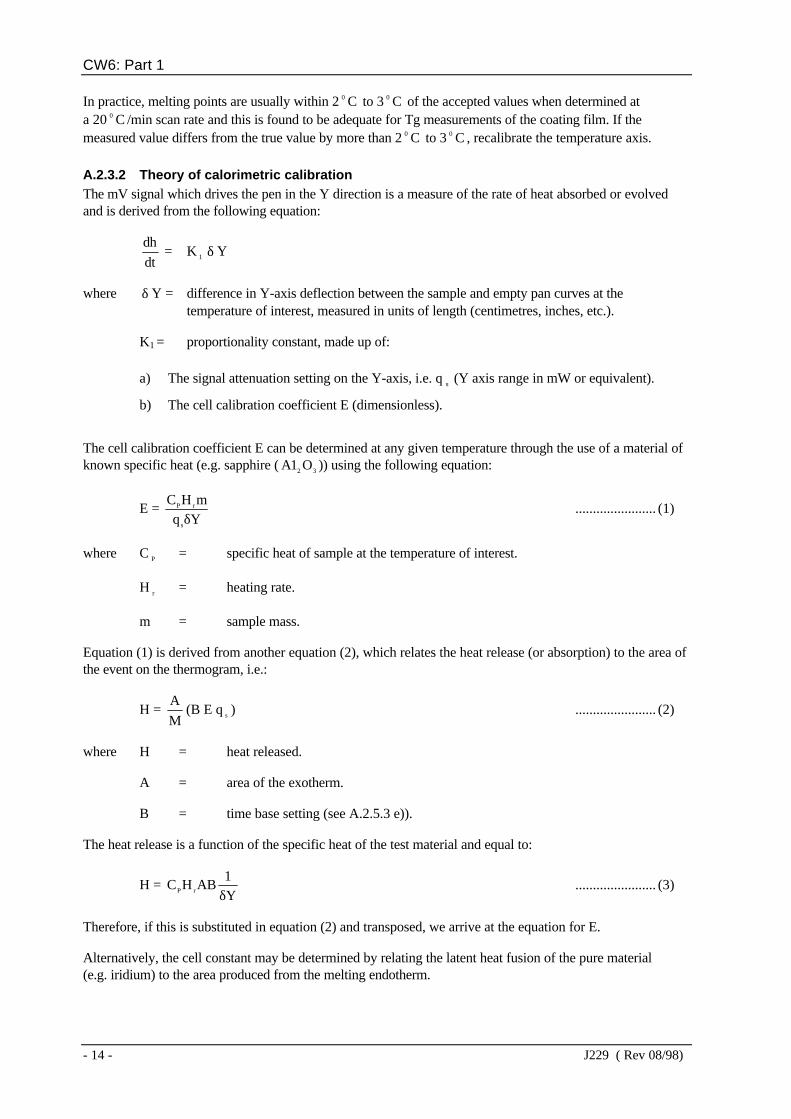
In practice, melting points are usually within 2 0 C to 3 0 C of the accepted values when determined ata 20 0 C /min scan rate and this is found to be adequate for Tg measurements of the coating film. If themeasured value differs from the true value by more than 2 0 C to 3 0 C , recalibrate the temperature axis.
A.2.3.2 Theory of calorimetric calibrationThe mV signal which drives the pen in the Y direction is a measure of the rate of heat absorbed or evolvedand is derived from the following equation:
dt
dh = K 1 δ Y
where δ Y = difference in Y-axis deflection between the sample and empty pan curves at thetemperature of interest, measured in units of length (centimetres, inches, etc.).
K1 = proportionality constant, made up of:
a) The signal attenuation setting on the Y-axis, i.e. qs
(Y axis range in mW or equivalent).
b) The cell calibration coefficient E (dimensionless).
The cell calibration coefficient E can be determined at any given temperature through the use of a material ofknown specific heat (e.g. sapphire ( 32 O1A )) using the following equation:
E = YqmHC
s
rP
δ....................... (1)
where C P = specific heat of sample at the temperature of interest.
H r = heating rate.
m = sample mass.
Equation (1) is derived from another equation (2), which relates the heat release (or absorption) to the area ofthe event on the thermogram, i.e.:
H = M
A(B E q s ) ....................... (2)
where H = heat released.
A = area of the exotherm.
B = time base setting (see A.2.5.3 e)).
The heat release is a function of the specific heat of the test material and equal to:
H = Y1
ABHC rP δ....................... (3)
Therefore, if this is substituted in equation (2) and transposed, we arrive at the equation for E.
Alternatively, the cell constant may be determined by relating the latent heat fusion of the pure material(e.g. iridium) to the area produced from the melting endotherm.

CW6: Part 1
J229 ( Rev 08/98) - 15 -
A.2.3.3 Method for determining the cell coefficient EA.2.3.3.1 Place two empty pans in the DSC cell and run a temperature programme between ambienttemperature and 300 0 C . If the trace is not almost horizontal, the baseline slope control shall be adjusted untilthe best line is achieved. A typical temperature calibration chart is shown in Figure A.1.
A.2.3.3.2 Load the sample pan with a weighed sapphire disc for a second run. Heat the pan up to the initialambient temperature and hold until equilibrium is obtained. This shall be achieved by setting the startingtemperature to ambient temperature and running in isothermal mode.
A.2.3.3.3 Run a second trace using the same final temperature as is used in A.2.3.3.1.
A.2.3.3.4 Measure several values for δ Y, the vertical difference between the traces, to calculate E values atthese points. The average of E over the range of interest shall be used.
A.2.4 SamplingWhen it is necessary to sample large amounts of powder from the sample batch (e.g. several kilogram boxes),take representative amounts (approximately 50 g) from each container, mix together and sample by coningand quartering. Analyse different batches separately.
Take a final sample (approximately 250 g) and store it in an airtight container, at a temperature not higherthan 0 0 C , in case subsequent testing is required. When the cold sample is taken from cold storage, allow atleast 30 min in its closed container to reach ambient temperature. Take powder for DSC tests directly from the250 g sample.
When amounts of powder less than 1 kg are involved, coning and quartering or riffle sampling is notnecessary.
Record the following information for each sample:
a) Date.
b) Time.
c) Powder lot number/batch number.
A.2.5 Test procedure
A.2.5.1 Instrument settingThe test procedure and instrument settings depend upon the design of equipment employed. However, thereare certain essential features in the test method which shall be followed if consistent and comparable resultsare to be obtained.
Where applicable, select a baseline slope setting which gives a virtually horizontal line when the referenceand sample pans are loaded identically. This is normally carried out with empty pans.
A.2.5.2 Preparation of test samplesWeigh out accurately between 10 mg and 15 mg of powder into an aluminium sample pan. Heavier weights(up to 25 mg) may be used, if needed, to give adequate sensitivity. The accuracy of weighing shall be± 0.1 mg.
A.2.5.3 Standard air testCarry out the standard air test under the following conditions:
a) Use open pans throughout.
b) Use an empty aluminium pan for the reference.

CW6: Part 1
- 16 - J229 ( Rev 08/98)
c) No purge gas is employed; carry out the test in static air at atmospheric pressure.
d) Appropriate experimental data recording conditions.
e) If exothermal areas are to be recorded accurately, it may be necessary with some instrumentsto change from a temperature base on the abscissa to one of time before the onset of cure.
f) Heat the sample from ambient temperature to 280 0 C at a rate of 20 0 C /min and record thetrace. Rapidly cool the sample to ambient temperature. Repeat this procedure for the secondrun, except that this run may be terminated at approximately 20 0 C in excess of the second runglass transition temperature (Tg
2).
The test temperature of 280 0 C may be subject to change depending on the type of coating material under test.It should be advised by the powder manufacturer.
A.2.5.4 Inert gas testCarry out the inert gas test as for the standard air test (see A.2.5.3), using an inert gas purge instead of staticair throughout the test. A flow rate of 40 ml/min shall be used.
A.2.5.5 Measuring the glass transition temperatureThe glass transition temperature (Tg) is defined as that temperature (or temperature range) at which thecoating polymer is transformed from a hard and often brittle material (the glass) into a tough, rubber-likematerial.
The glass transition temperature of the cured material is visible on the DSC trace as a baseline shift, resultingfrom a marked step-like change in specific heat at Tg, the step usually covering several degrees. It isconventional to take Tg as the point of intersection of the extrapolated baseline at the low temperature end andthe tangent of the curve at the inflection point (see Figure A.2). For raw powders, the Tg usually takes theform of a baseline shift with a superimposed endothermic peak (see Figure A. 3).
A.2.5.6 Measuring the heat released during cureIt is necessary to measure the area under the curing exotherm either in the determination of thermal stability,or when the quality of oversprayed powder is in question.
There are several ways of measuring the exothermal area which vary in their accuracy. These are:
a) Electronic integration using a computer or a dedicated integrator.
b) Planimeter.
c) Cut out the exothermal area marked on the chart paper, weigh it and compare it with theweight of a known area of the same paper.
d) Count the squares within the exothermal area marked on the chart paper.
One of these, or a similar method, shall be selected for use with the DSC.
The points at which the cure exotherm commences and ends are used to calculate the heat release. They areusually determined by drawing in the baseline to the exotherm using a rule. Care must be taken to distinguishbetween the onset of cure (T
oc) and the onset of flow (T
of) and to commence the baseline at T
oc
(see Figure A. 3).
A.3 MEASUREMENT OF DEGREE OF CURE OF POWDER COATING
A.3.1 PrincipleThe method of assessment of the cure of the powder coating film cure by measurement of its glass transitiontemperature consists of heating a ground coating sample at a constant rate in a DSC. A first trace is made

CW6: Part 1
J229 ( Rev 08/98) - 17 -
which records thermal changes in the sample between ambient temperature and some point after full cure asdefined by the powder manufacturer. The sample is cooled to ambient temperature and a second run carriedout. The glass transition temperatures before and after heating are determined and are used to assess thedegree of cure. It is essential that samples are initially pretreated in the calorimeter to remove moisture and toconfer a uniform thermal history.
A.3.2 ApparatusThe apparatus used shall be a DSC with sufficient calorimetric sensitivity to respond to the glass transitiontemperature of the materials under test (the thermal analysis curve should display the heat flow rate at asensitivity of cm/W400µ minimum). Additionally, the following accessories will be required:
a) Aluminium sample pans.
b) Quench cooling accessory.
c) Analytical balance capable of weighing to an accuracy of 0.1 mg.
d) Liquid nitrogen or other cooling fluid. Alternatively, a DSC with a built-in cooling device isacceptable provided it can cool the sample rapidly at the rate required in the method.
e) Hammer and cold chisel.
f) Microhammer mill or equivalent.
A.3.3 Temperature axis calibrationThe method to be used for checking the temperature axis calibration is as follows:
a) Calibrate the upper temperature scale of the DSC using samples of pure indium, tin and leadwhich have melting points of 156.6 0 C , 231.9 0 C and 327.4 0 C respectively.
b) Melt the samples in open pans in either static air or under an inert gas purge, depending on thetest procedure being followed.
c) Take the melting point as the intersection of the leading edge of the fusion endotherm with theprojected baseline.
The results obtained are influenced by the scan rate, therefore adjust the instrument such that these values arecorrect at the scanning rate employed in the test, i.e. 20 0 C /min.
In practice, melting points are usually within 2 0 C to 3 0 C of the true values when determined at a20 0 C /min scan rate and this is found to be adequate for Tg measurements of the coating film. When thetemperature deviation is higher than this, it is necessary to adjust the sample thermocouple reference junction.
If adjustment has been necessary to bring within limits, carry out a further calibration to demonstrate that theinstrument is calibrated accurately.
A.3.4 SamplingRemove coating film samples from the coated component using a hammer and cold chisel. This producesfurled coating flakes. Care should be taken to remove samples of full film thickness, but at the same timeavoid the inclusion of steel debris.
Sample a component at several points along its length and around its circumference. Take samples from testpanels in a similar manner.
Collect the coating flakes in a plastics bag and identify. Grind the flakes to pieces small enough to passthrough a 2.8 mm aperture sieve in a microhammer mill. Record the following information for each sample:

CW6: Part 1
- 18 - J229 ( Rev 08/98)
a) Date.
b) Time.
c) Component number.
d) Sequence number.
e) Powder lot number/batch number.
f) Location of sample on component.
A.3.5 Test procedure
A.3.5.1 Instrument settingThe test procedure and instrument settings used depends upon the design of equipment involved. However,there are certain essential features in the test method which shall be followed if consistent and comparableresults are to be obtained.
Where applicable, select a baseline slope setting which gives a virtually horizontal line when the referenceand sample pans are loaded identically. This is normally carried out with empty pans.
A.3.5.2 Preparation of test samplesWeigh out accurately between 10 mg and 15 mg of ground coating into an aluminium sample pan. Heavierweights (up to 25 mg) may be used, if needed, to give adequate sensitivity. The accuracy of weighing shallbe 0 0.1 mg.
A.3.5.3 Standard air testCarry out the standard air test under the following conditions:
a) Use open pans to assist the release of moisture from the sample during pretreatment.
b) Use an empty aluminium pan for the reference.
c) No purge gas is employed; carry out the test in static air at atmospheric pressure.
d) Appropriate experimental data recording conditions.
e) It will normally be necessary to subject the coating sample to thermal pretreatment beforeassessment of its degree of cure. Pretreatment is designed to remove any absorbed moisturefrom the coating because moisture is known to influence glass transition temperaturemeasurements. Such pretreatment shall not significantly advance the cure of the coatingsample.
The powder Manufacturer should specify the thermal pretreatment required for the product.This will typically require heating the sample in the DSC cell from ambient temperature(i.e. 20 0 C to 25 0 C ) to some defined temperature higher than 100 0 C , probably in the range100 0 C to 150 0 C . This required temperature will typically be attained within 120 s and heldfor a period up to 60 s. Immediately cool the sample to ambient temperature with liquidnitrogen or a suitable cooling fluid; alternatively, a DSC with a built-in cooling device isacceptable provided it can cool the sample rapidly at the rate required in the method.
Make a suitable record of the pretreatment run.
f) Heat the sample from ambient temperature to a temperature specified by the Manufacturer, ata rate of 20 0 C /min, so that the sample achieves full cure, but avoids significant degradation.Rapidly cool the sample to ambient temperature using liquid nitrogen or a suitable coolingfluid. This establishes the first glass transition temperature (Tg
1).
Repeat the procedure for the second run, except that this run may be terminated atapproximately 20 0 C higher than the second glass transition temperature (Tg
2).

CW6: Part 1
J229 ( Rev 08/98) - 19 -
Make pen records of both (Tg1
) and (Tg2
) runs.
A.3.5.4 Inert gas testCarry out the inert gas test as for the standard air test (see A.3.5.3), using an inert gas purge instead of staticair throughout the test. Use a flow rate of 40 ml/min throughout the test.
A.3.5.5 Measuring the glass transition temperatureThe glass transition temperature (Tg) is defined as that temperature (or temperature range) at which thecoating polymer is transformed from a hard and brittle material (the glass) into a tough, rubber-like material.
The glass transition temperature is visible on the DSC trace as a baseline shift, resulting from a markedstep-like change in specific heat at Tg, the step usually covering several degrees. It is conventional to take Tgas the point of intersection of the extrapolated baseline at the low temperature end and the tangent of the curveat the inflection point (see Figure A.2).

CW6: Part 1
- 20 - J229 ( Rev 08/98)
FIGURE A.1 - Typical temperature calibration

CW6: Part 1
J229 ( Rev 08/98) - 21 -
FIGURE A.2 - Typical DSC traces - Glass transition temperature

CW6: Part 1
- 22 - J229 ( Rev 08/98)
FIGURE A.3 - Typical DSC traces - Enthalpy H

CW6: Part 1
J229 ( Rev 08/98) - 23 -
APPENDIX B
FLEXIBILITY TEST
B.1 LABORATORY PREPARED TEST PANELSB. 1.1 Apply the coating to steel plates 50 mm x 300 mm x 6 mm thick and properly cure. Bend (at adeflection rate of 25 mm/min) over appropriate sized mandrels (see B. 1.2) at two substrate test temperatures(5 0 C and 20 0 C ). After bending, the coating shall not crack, disbond or pinhole when holiday tested inaccordance with Appendix C. Inspect plates immediately after bending and again after 24 h at 20 0 C .
B.1.2 Select mandrel sizes according to the following formula:
D = S
St )1( −
where D = mandrel diameter, in mm (see Figure B.1).
t = plate thickness, in mm.
S = one of the values in clause B.3 depending on the intended coating application and the temperature of the test.
The arc length of the mandrel shall be fixed at 225 ± 25 mm.
B.1 .3 Set the panel support gap set according to the following formula:
Support gap = M + 2t + 4 mm
where M = chord length across the mandrel arc, in mm (see Figure B.1).
t = plate thickness, in mm.
Bend the panel until it makes contact with the entire surface area of the mandrel.
B.1 .4 During bending, peaking (point at which a gap occurs between the mandrel and the panel) may beobserved at the centre of the panel. In this case, the area of the panel where the gap exceeds 0.254 mm(0.010 in.) shall be disregarded in evaluating the test results. This area shall not exceed 25% of the mandrelsurface area.
B.2 TESTS ON PIPE SPECIMENSB.2.1 Cold cut test specimens 356 mm long x 50 mm wide from a pipe section with the long axis in thecircumferential direction. Where seamless pipe is being tested, select specimens which show a minimalvariation in pipe wall thickness, particularly within the test area (i.e. middle 75 mm to 100 mm of specimen).Bend the test specimens over appropriate sized mandrels at two substrate test temperatures (5 0 Cand 20 0 C ). After bending, the coating shall not exhibit visible signs of cracks, disbonding or pinholes andshall pass a holiday detection test when tested in accordance with Appendix C. Inspect specimens immediatelyafter bending and again after 24 h at 20 0 C .
B.2.2 Select mandrel sizes according to the following formula:
D1
= t
tD1
tS
1
o
−
−+
CW6: Part 1
- 24 - J229 ( Rev 08/98)
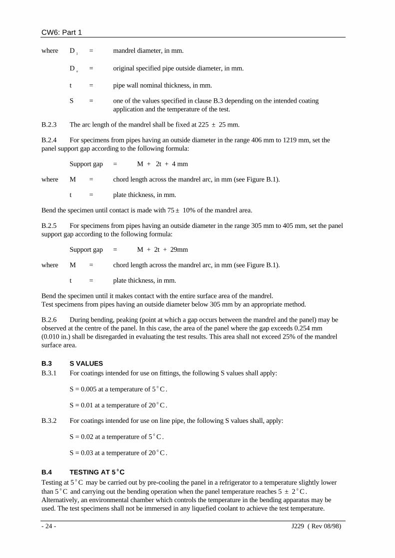
where D1
= mandrel diameter, in mm.
Do
= original specified pipe outside diameter, in mm.
t = pipe wall nominal thickness, in mm.
S = one of the values specified in clause B.3 depending on the intended coatingapplication and the temperature of the test.
B.2.3 The arc length of the mandrel shall be fixed at 225 ± 25 mm.
B.2.4 For specimens from pipes having an outside diameter in the range 406 mm to 1219 mm, set thepanel support gap according to the following formula:
Support gap = M + 2t + 4 mm
where M = chord length across the mandrel arc, in mm (see Figure B.1).
t = plate thickness, in mm.
Bend the specimen until contact is made with 75 ± 10% of the mandrel area.
B.2.5 For specimens from pipes having an outside diameter in the range 305 mm to 405 mm, set the panelsupport gap according to the following formula:
Support gap = M + 2t + 29mm
where M = chord length across the mandrel arc, in mm (see Figure B.1).
t = plate thickness, in mm.
Bend the specimen until it makes contact with the entire surface area of the mandrel.Test specimens from pipes having an outside diameter below 305 mm by an appropriate method.
B.2.6 During bending, peaking (point at which a gap occurs between the mandrel and the panel) may beobserved at the centre of the panel. In this case, the area of the panel where the gap exceeds 0.254 mm(0.010 in.) shall be disregarded in evaluating the test results. This area shall not exceed 25% of the mandrelsurface area.
B.3 S VALUESB.3.1 For coatings intended for use on fittings, the following S values shall apply:
S = 0.005 at a temperature of 5 0 C .
S = 0.01 at a temperature of 20 0 C .
B.3.2 For coatings intended for use on line pipe, the following S values shall, apply:
S = 0.02 at a temperature of 5 0 C .
S = 0.03 at a temperature of 20 0 C .
B.4 TESTING AT 5 C0
Testing at 5 0 C may be carried out by pre-cooling the panel in a refrigerator to a temperature slightly lowerthan 5 0 C and carrying out the bending operation when the panel temperature reaches 5 ± 2 0 C .Alternatively, an environmental chamber which controls the temperature in the bending apparatus may beused. The test specimens shall not be immersed in any liquefied coolant to achieve the test temperature.

CW6: Part 1
J229 ( Rev 08/98) - 25 -
FIGURE B.1 - Typical mandrel for flexibility tests

CW6: Part 1
- 26 - J229 ( Rev 08/98)
APPENDIX C
HOLIDAY DETECTION OF COATINGS
C.1 EQUIPMENTHoliday detection shall be carried out using dc, non-pulsing holiday detection equipment on surfaces attemperatures below 90 0 C and free from moisture.
C.2 OPERATING VOLTAGEThe operating voltage shall be 125 V per m25µ of coating thickness.
The rate of travel of the probe over the surface shall not exceed 300 mm/s.
C.3 ELECTRODE TYPEFor all coating systems the wire brush type of electrode shall be used, suitably curved to conform to thecontour of the coated surface of pipe. For fittings, a suitable procedure shall be agreed with the coatingapplicator and shall normally be the one that is approved within the procedure qualification.
C.4 IDENTIFICATION METHODAll holidays shall be identified with a waterproof marker.
C.5 EQUIPMENT CALIBRATIONAll holiday detectors shall be calibrated at the beginning of every working day and, additionally, whenrequested by Transco.

CW6: Part 1
J229 ( Rev 08/98) - 27 -
APPENDIX D
EVALUATION OF RESISTANCE TO IMPACT
D.1 GENERALThe procedures specified in clauses D.2 to D.6 inclusive serve to assess the comparative resistance ofcoatings to impact damage.
D.2 TEST EQUIPMENTThe following test equipment will be required:
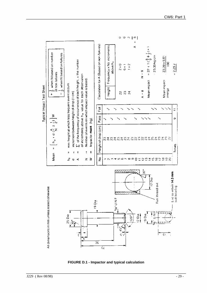
a) A variable impact tester (ASTM G14-77, paragraph 4.2 or equivalent) with punch hammertype indentor modified as shown in Figure D.1 to accommodate a 14.3 mm diameter ballbearing and equipped with a minimum impact mass of 1 kg.
b) A sufficient supply of 14.3 mm diameter ball bearings manufactured from EN31 steel with aVickers hardness of 800 to 930.
c) A holiday detector (see Appendix C).
d) A thickness gauge.
e) Repair materials.
D.3 TEST PROCEDURE ON COMPONENTSD.3.1 Check the test site to ensure that it is free from holidays with the holiday detector set at the requiredvoltage for the particular coating film (see clause C.2).
D.3.2 Position the impact tester on a holiday free site 300 ± 50 mm from one end of the component.
D.3.3 Drop the impact weight from a height calculated to impart the specified impact energy to thecoating. The impact height may be calculated using the following formula:
H = W81.9
J
where H = impactor height, in m.
W = impactor mass, in kg.
J = impact energy, in joules.
D.3.4 Retest the impact area for holidays using the detector set at the required operating voltage
D.3.5. Repeat D.3.2, D.3.3 and D.3.4 at four more locations evenly spaced over the surface of thecomponent.
D.3.6 Rotate the ball bearing after each impact.
D.3.7 After every 20 impacts fit a new ball bearing.
D.3.8 If a holiday is caused by the impact test, check the coating thickness in the test area using athickness gauge.
CW6: Part 1
- 28 - J229 ( Rev 08/98)
D.4 REPAIR PROCEDURE FOR COMPONENTSRepair any holiday caused by impact testing using repair materials.
D.5 TEST PROCEDURE ON PANELSD.5.1 Test sample panels (300 mm x 50 mm x 6 mm) and test panels (300 mm x 50 mm) cold cut fromcomponent in the longitudinal direction according to the procedure detailed in ASTM G14-77, paragraphs6 to 9, using the apparatus detailed in clause D.2 a). The additional modifications to the ASTM procedurespecified in D.5.2 to D.5.6 inclusive shall apply.
D.5.2 Test impact areas for failure using the holiday detector set at a voltage of 125 V per m25µ of
coating thickness (this relates to coating thickness before impact damage).
D.5.3 The minimum spacing between impacts along the centre line of the specimen shall be 25 mm.
D.5.4 Rotate the ball bearing after each impact.
D.5.5 After every 20 impacts fit a new ball bearing.
D.5.6 Increase the height by an increment of 10 mm between impacts.
D.5.7 There shall be no disbonding at the minimum impact energy. Verify this by testing in accordancewith clause E.6 and report in accordance with clause E.7.
D.6 REPORTING RESULTSD.6. 1 If the coating withstands the specified impact energy without forming a holiday, the test shall berecorded as a 'Pass'. If a holiday is formed at the specified impact energy, the test shall be reported as 'Fail atthickness of...' and the measured coating thickness shall be recorded.
D.6.2 The impact strength shall be converted to impact energy in joules and this value shall be reported.(A typical calculation is shown in Figure D.1).
CW6: Part 1
J229 ( Rev 08/98) - 29 -
FIGURE D.1 - Impactor and typical calculation

CW6: Part 1
- 30 - J229 ( Rev 08/98)
APPENDIX E
EVALUATION OF RESISTANCE TO WATER IMMERSION
E.1 GENERALThe equipment and procedure detailed in clauses E.2 to E.7 inclusive shall be used to assess the comparativeresistance of coatings applied to components (free of holidays) to loss of adhesion due to water absorption.
E.2 EQUIPMENTThe following equipment will be required:
a) A water bath which shall be maintained at a temperature of 50 ± 2 0 C .
b) A holiday detector.
c) Internal pipe coating material (complying with CM2).
d) 6 mm diameter twist drill.
e) Pointed sharp knife, e.g. Stanley type or similar.
f) 5 mm diameter steel rod 450 mm long.
g) Elastomeric adhesive for repairing test areas, e.g. Silastic silicone-rubber, grades RTV 738 orRTV 732 or equivalent.
E.3 SAMPLE PREPARATION
E.3.1 Laboratory prepared specimensPrepare 300 mm x 50 mm x 6 mm panels under conditions of application and cure similar to those for acoated component.
E.3.2 Specimens taken from componentsCold cut 300 mm x 50 mm specimens from a sample pipe or, in the case of a fitting, from the pipe pup whichhas been coated as a test piece.
E.4 PREPARATION OF TEST AREAE.4.1 To ensure freedom from holidays, test the prepared panels for holidays with the holiday detector setat the required voltage (see clause C.2).
E.4.2 Drill a 6 mm diameter hole through the test panel within 25 mm of one end.
E.4.3 Protect the bare metal of the panel with internal coating material (see clause E.2 c)).
E.5 INITIAL TEST PROCEDUREE.5.1 Carry out an initial adhesion test as described in clause E.6.
E.5.2 Using the steel rod fitted through the 6 mm diameter hole, suspend the specimen panel in the waterbath immersing all but the top 50 mm of the panel.
E.5.3 At intervals of 24 h, remove the panel from the water bath and allow it to cool to ambienttemperature.
E.5.4 Test the coating adhesion as specified in clause E.6.
E.5.5 Repair the test area using elastomeric adhesive.

CW6: Part 1
J229 ( Rev 08/98) - 31 -
E.5.6 Return the panel to the water bath immediately.
E.5.7 If, after seven days immersion, the coating is retested and is found to be satisfactory, return thepanel to the water bath and repeat the adhesion test at intervals of seven days up to a total immersion time of28 days.
E.6 INVESTIGATION PROCEDUREE.6.1 Use one or other of the following procedures (E.6.2, E.6.3) as appropriate.
E.6.2 For all coated components and coatings on panels equal to or less than m600µ thickness, use the
following procedure:
a) Using a sharp pointed knife (e.g. Stanley knife or similar), make two incisions approximately13 mm long through to the metal surface to form a V with an angle of approximately 30 0 atthe intersection point.
b) Starting at the point of intersection force the coating from the steel substrate using the sharppointed knife. Take care to protect the eyes and hands when carrying out this operation.
E.6.3 For laboratory panels with coatings greater than m600µ thickness use the following procedure:
a) Using a small hacksaw blade (e.g. 'Junior' type or similar) make two incisions through to themetal surface to form an X with an angle of approximately 30 0 at the point of intersection.
b) Draw a sharp knife along the cut lines to ensure that the hacksaw blade has reached the metalsurface.
c) Starting at the point of intersection, force the coating from the steel substrate using the sharppointed knife. Take care to protect the eyes and hands when carrying out this operation.
E.7 REPORTING RESULTSRefusal of the coating to peel or a cohesive failure within the coating shall be recorded as a 'Pass'.
Cohesive failure, caused by voids leaving a honeycomb structure on the specimen surface, shall constitute a'Fail' condition.
For the purpose of this test, cohesive failure will be recorded where some coating material remains on themetal surface and where difficulty in coating removal has been experienced.
The extent of the adhesive failure between the coating and the metal substrate shall be recorded.

CW6: Part 1
- 32 - J229 ( Rev 08/98)
APPENDIX F
EVALUATION OF RESISTANCE TO CATHODIC DISBONDING
F.1 GENERALThe procedures detailed in clauses F.2 to F.8 inclusive serve to assess the comparative resistance of damagedpipe coatings to disbonding when exposed to cathodic protection in potentially corrosive soils.
F.2 TEST REQUIREMENT
F.2.1 ApparatusThe following apparatus will be required:
a) A stabilized dc power unit having a voltage output of 12 V and a capability to supply 20 mAsimultaneously to each test area in circuit. A suitable circuit is shown in Figure F.1 a).
b) Digital voltmeter, range 1.999 V (3.5 digit), input impedance 10 3 M Ω . Accuracy of 0.1% ± 1digit at 20 ± 1 0 C .
c) Variable resistor, range 1 k Ω ± 10%, 1 W (one required for each specimen).
d) 75 mm length of 0.8 mm diameter platinum wire, or similar length of 6 mm wide, 1.5 mm thickplatinized titanium strip (one required for each test area).
e) Holiday detection equipment.
f) Reference electrode of the saturated calomel type, constructed from glass or plastics withporous plug. The diameter should be not greater than 10 mm.
g) 6 mm diameter twist drill with included cutting angle of 160 0 .
h) Equipment for maintaining the temperature of the specimens and test areaat 20 ± 2 0 C .
i) A length of rigid plastics pipe per test area to be used as a solution container (approximatedimensions 60 mm long x 50 mm nominal bore).
j) Elastomeric adhesive for fixing the plastics pipe to the test surface, e.g. a silastic siliconerubber grade RTV 738 or RTV 732 or equivalent material.
k) Fixed resistor, 1 Ω ± 2%, 1 W (one required for each test area).
F.2.2 ReagentAn electrolyte comprising a sodium chloride (NaCl) solution, (3% W/V). 30 g of NaCl should be dissolved indistilled water and made up to 1 litre.
F.3 PREPARATION OF TEST PANELS
F.3.1 Laboratory prepared specimensSample panels 300 mm x 50 mm x 6 mm shall be prepared simulating the conditions of application for afactory coated pipe.
F.3.2 Specimens taken from componentsTest panels 300 mm x 50 mm shall be cut from a sample production coated pipe.
CW6: Part 1
J229 ( Rev 08/98) - 33 -
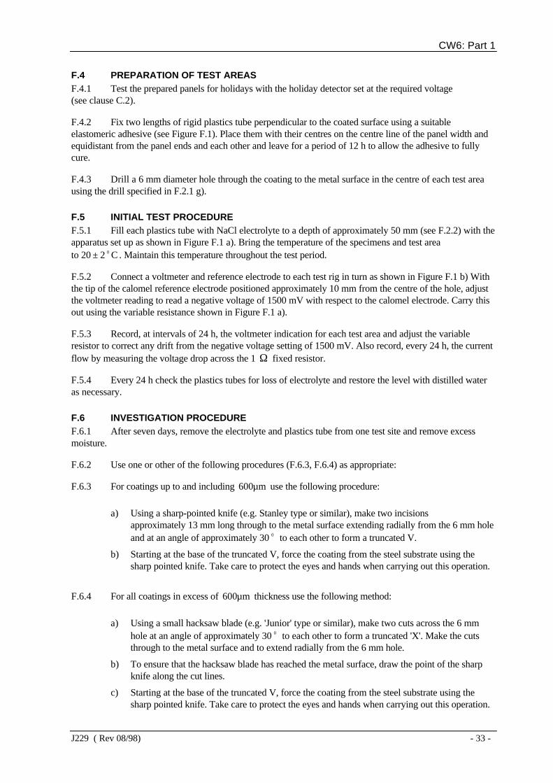
F.4 PREPARATION OF TEST AREASF.4.1 Test the prepared panels for holidays with the holiday detector set at the required voltage(see clause C.2).
F.4.2 Fix two lengths of rigid plastics tube perpendicular to the coated surface using a suitableelastomeric adhesive (see Figure F.1). Place them with their centres on the centre line of the panel width andequidistant from the panel ends and each other and leave for a period of 12 h to allow the adhesive to fullycure.
F.4.3 Drill a 6 mm diameter hole through the coating to the metal surface in the centre of each test areausing the drill specified in F.2.1 g).
F.5 INITIAL TEST PROCEDUREF.5.1 Fill each plastics tube with NaCl electrolyte to a depth of approximately 50 mm (see F.2.2) with theapparatus set up as shown in Figure F.1 a). Bring the temperature of the specimens and test areato 20 ± 2 0 C . Maintain this temperature throughout the test period.
F.5.2 Connect a voltmeter and reference electrode to each test rig in turn as shown in Figure F.1 b) Withthe tip of the calomel reference electrode positioned approximately 10 mm from the centre of the hole, adjustthe voltmeter reading to read a negative voltage of 1500 mV with respect to the calomel electrode. Carry thisout using the variable resistance shown in Figure F.1 a).
F.5.3 Record, at intervals of 24 h, the voltmeter indication for each test area and adjust the variableresistor to correct any drift from the negative voltage setting of 1500 mV. Also record, every 24 h, the currentflow by measuring the voltage drop across the 1 Ω fixed resistor.
F.5.4 Every 24 h check the plastics tubes for loss of electrolyte and restore the level with distilled wateras necessary.
F.6 INVESTIGATION PROCEDUREF.6.1 After seven days, remove the electrolyte and plastics tube from one test site and remove excessmoisture.
F.6.2 Use one or other of the following procedures (F.6.3, F.6.4) as appropriate:
F.6.3 For coatings up to and including m600µ use the following procedure:
a) Using a sharp-pointed knife (e.g. Stanley type or similar), make two incisionsapproximately 13 mm long through to the metal surface extending radially from the 6 mm holeand at an angle of approximately 30 0 to each other to form a truncated V.
b) Starting at the base of the truncated V, force the coating from the steel substrate using thesharp pointed knife. Take care to protect the eyes and hands when carrying out this operation.
F.6.4 For all coatings in excess of m600µ thickness use the following method:
a) Using a small hacksaw blade (e.g. 'Junior' type or similar), make two cuts across the 6 mmhole at an angle of approximately 30 0 to each other to form a truncated 'X'. Make the cutsthrough to the metal surface and to extend radially from the 6 mm hole.
b) To ensure that the hacksaw blade has reached the metal surface, draw the point of the sharpknife along the cut lines.
c) Starting at the base of the truncated V, force the coating from the steel substrate using thesharp pointed knife. Take care to protect the eyes and hands when carrying out this operation.

CW6: Part 1
- 34 - J229 ( Rev 08/98)
F.6.5 Repeat the investigation procedure at the second test site after 28 days.
F.7 REPORTING OF RESULTSThe amount of disbonding shall be quoted as the radial distance from the edge of the pre-damage to which thecoating peels easily from the metal surface.

CW6: Part 1
J229 ( Rev 08/98) - 35 -
a) Cathodic disbonding test rig
b) Voltage adjustment circuit
FIGURE F.1 - Cathodic disbonding test apparatus

CW6: Part 1
- 36 - J229 ( Rev 08/98)
APPENDIX G
STRAIN/POLARIZATION TESTG.1 Bend the test sections in accordance with the method detailed in Appendix B using a valueof S = 0.02 for line pipe powders and S = 0.005 for fitting powders at a temperature of 20 ± 2 0 C .
G.2 Polarize the specimens, as detailed in Appendix F, with a single test site selected on the minimumradius of the bend, i.e. area of maximum strain. After 28 days polarization, remove the electrolyte and plasticstube and remove excess moisture.
G.3 The area of coating exposed to the electrolyte shall not exhibit signs of cracks, disbondment orpinholes and shall pass a holiday detection test as detailed in Appendix C.