CUSTOM SPRING DESIGN &...
11
CUSTOM SPRING DESIGN & MANUFACTURE Springs can be designed to an almost unlimited variety of configurations and over the years Lee Spring has manufactured literally tens of thousands of ‘custom’ designed springs. Custom designs are usually considered when either the performance characteristics required (e.g. environmental conditions, product life cycle, and load capabilities) or physical size and configuration requirements exceed the scope of what is available from Lee Spring’s comprehensive stock range. On page 210 you will find a Glossary which will help explain the terminology used when specifying custom springs as well as specification forms for several types of common springs. We have included brief guidelines to further assist selection. Lee Spring also has the capability to produce many other types of springs, washers, wire forms and stampings as well as assemblies of these products. Please contact us to discuss your particular application. Conical Springs Swivel Hook Springs Drawbar Springs 196 +44 (0)118 978 1800 | www.leespring.com or www.leespring.co.uk | +44 (0)118 977 4832 | [email protected]
-
Upload
truongcong -
Category
Documents
-
view
215 -
download
0
Transcript of CUSTOM SPRING DESIGN &...

C U S T O M S P R I N G D E S I G N & M A N U FA C T U R E
Springs can be designed to an almost unlimited variety of configurations and over the years Lee Spring has
manufactured literally tens of thousands of ‘custom’ designed springs.
Custom designs are usually considered when either the performance characteristics required (e.g. environmental
conditions, product life cycle, and load capabilities) or physical size and configuration requirements exceed the
scope of what is available from Lee Spring’s comprehensive stock range.
On page 210 you will find a Glossary which will help
explain the terminology used when specifying
custom springs as well as specification forms
for several types of common springs. We
have included brief guidelines to further
assist selection.
Lee Spring also has the capability to produce many other types of springs, washers,
wire forms and stampings as well as assemblies of these
products. Please contact us to discuss your particular application.
Conical Springs Swivel Hook Springs Drawbar Springs
196 ������+44 (0)118 978 1800 | �����www.leespring.com or www.leespring.co.uk | �����+44 (0)118 977 4832 | ������[email protected]

197������+44 (0)118 978 1800 | �����www.leespring.com or www.leespring.co.uk | �����+44 (0)118 977 4832 | ������[email protected]
WAV E S P R I N G S S P E C I F I C AT I O N F O R M
CUSTOMER NAME: A/C No:
CUSTOMER CONTACT
TEL No: EMAIL:
ENQUIRY TAKEN BY:
DATE TO SUPPLIER:
DATE PRICE RECEIVED:
INDICATE UNITS OF MEASURE (IN. & LB.), (MM & N)
1. MATERIAL _______________________________________
2. WIRE THICKNESS _________________________________
3. RADIAL WALL ____________________________________
4. DIRECTION OF WIND OPT LH RH
OUTSIDE DIAMETER ______________________________
INSIDE DIAMETER ________________________________
5. FREE HEIGHT _____________________________________
6. RATE _____ +/- _______ BETWEEN ______ & ________
7. LOAD 1 _________ +/- __________ @ ____________
8. LOAD 2 _________ +/- __________ @ ____________
9. HOLE DIAMETER _________________________________
10. ROD DIAMETER __________________________________
11. NUMBER OF TURNS _______________________________
12. WAVES PER TURN ________________________________
13. SQUARENESS _____________________________________
14. FINISH ___________________________________________
15. FREQUENCY OF COMPRESSION ________ CYCLES/SEC. AND WORKING RANGE
________ HEIGHT 1 TO_________ HEIGHT 2
16. OPERATING TEMP. _________ °F/°C
17. OTHER: __________________________________________
_________________________________________________
Equal Deflectionand Load
ReducedOperating
Height
LOAD LOAD
REDUXTM Wave Spring
Coil Spring
OPERATESIN HOLE
DIAMETER
CLEARSROD
DIAMETER
RADIALWALL
FREE HEIGHT
TURNS
WAVES PER TURNLOAD AT WORKING HEIGHT
WIRETHICKNESS
QUANTITY TO QUOTE FOR ____________________________________________________________________________________________
198 ������+44 (0)118 978 1800 | �����www.leespring.com or www.leespring.co.uk | �����+44 (0)118 977 4832 | ������[email protected]
CONSTANT FORCE SPR INGS SPECIF ICAT ION FORM
CUSTOMER NAME: A/C No:
CUSTOMER CONTACT
TEL No: EMAIL:
ENQUIRY TAKEN BY:
DATE TO SUPPLIER:
DATE PRICE RECEIVED:
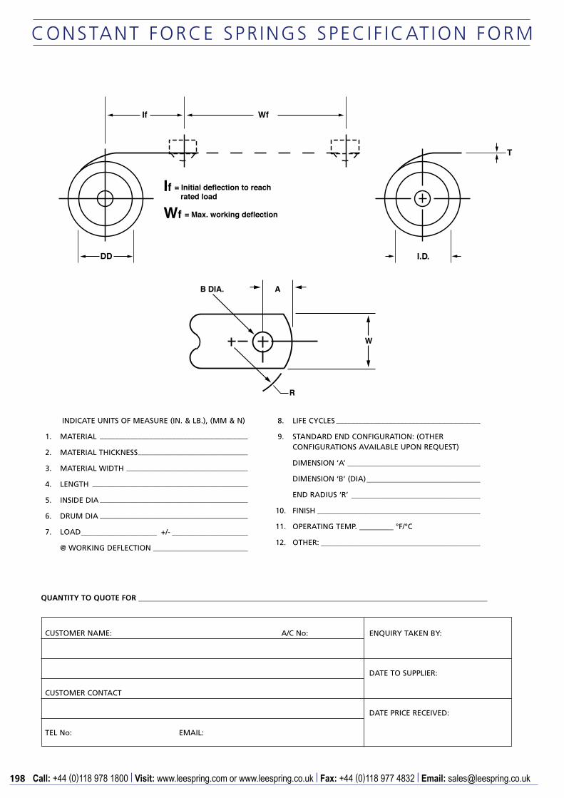
INDICATE UNITS OF MEASURE (IN. & LB.), (MM & N)
1. MATERIAL _______________________________________
2. MATERIAL THICKNESS _____________________________
3. MATERIAL WIDTH ________________________________
4. LENGTH _________________________________________
5. INSIDE DIA _______________________________________
6. DRUM DIA _______________________________________
7. LOAD ____________________ +/- ____________________
@ WORKING DEFLECTION _________________________
8. LIFE CYCLES ______________________________________
9. STANDARD END CONFIGURATION: (OTHER CONFIGURATIONS AVAILABLE UPON REQUEST)
DIMENSION ‘A’ ___________________________________
DIMENSION ‘B’ (DIA) ______________________________
END RADIUS ‘R’ __________________________________
10. FINISH ___________________________________________
11. OPERATING TEMP. _________ °F/°C
12. OTHER: __________________________________________
If
DD I.D.
T
Wf
If = Initial deflection to reach rated load
Wf = Max. working deflection
R
W
B DIA. A
QUANTITY TO QUOTE FOR ____________________________________________________________________________________________

199������+44 (0)118 978 1800 | �����www.leespring.com or www.leespring.co.uk | �����+44 (0)118 977 4832 | ������[email protected]
LHRH
IVIIIIII
OPEN ENDS, GROUND.
OPEN ENDS, NOT GROUND.
CLOSED ENDS, NOT GROUND.
CLOSED & GROUND ENDS.
MAX SOLID HEIGHT
FREE LENGTH +/-
OR WORKS IN
+/-
OUTSIDE DIAMETER
OR WORKS OVER
+/-
INSIDE DIAMETER
C O M P R E S S I O N S P R I N G S S P E C I F I C AT I O N F O R M
Compression springs are generally specified to work in a bore or over a rod. They can be supplied with end coils closed and ground square for optimum alignment and reduced solid height. Springs can also be pre-stressed during manufacture to maintain length at elevated stress levels.
INDICATE UNITS OF MEASURE (IN & LB), (MM & N)
1. MATERIAL
2. WIRE DIA.
3. DIRECTION OF WIND OPT LH RH
4. STYLE OF END I II III IV
5. SQUARENESS
6. RATE +/- BETWEEN &
7. LOAD 1 +/- @
8. LOAD 2 +/- @
9. No. OF ACTIVE COILS
10. TOTAL No. OF COILS
11. FINISH
12. FREQUENCY OF COMPRESSION CYCLES/SEC
AND WORKING RANGE LENGTH 1 TO LENGTH 2
13. OPERATING TEMP °c
14. OTHER
CUSTOMER NAME: A/C No:
CUSTOMER CONTACT
TEL No: EMAIL:
ENQUIRY TAKEN BY:
DATE TO SUPPLIER:
DATE PRICE RECEIVED:
QUANTITY TO QUOTE FOR ____________________________________________________________________________________________

200 ������+44 (0)118 978 1800 | �����www.leespring.com or www.leespring.co.uk | �����+44 (0)118 977 4832 | ������[email protected]
I II
CLOSED ENDS, NOT GROUND.
CLOSED & GROUND ENDS.
+/-
+/-
+/-
INSIDE DIAMETER
FREE LENGTH
MAX SOLID HEIGHT
OUTSIDE DIAMETER
C O N I C A L S P R I N G S S P E C I F I C AT I O N F O R M
Conical springs are specified where the large end is designed to work in a bore and the small end fits over a rod. Springs of this type offer reduced solid height compared to straight compression springs, especially when they are capable of ‘telescoping’.
INDICATE UNITS OF MEASURE (IN & LB), (MM & N)
1. MATERIAL
2. WIRE DIA.
3. DIRECTION OF WIND OPT LH RH
4. STYLE OF END I II
5. RATE +/- BETWEEN &
6. LOAD 1 +/- @
7. LOAD 2 +/- @
8. No. OF ACTIVE COILS
9. TOTAL No. OF COILS
10. FINISH
11. FREQUENCY OF COMPRESSION CYCLES/SEC
AND WORKING RANGE LENGTH 1 TO LENGTH 212. OPERATING TEMP °c
13. OTHER
CUSTOMER NAME: A/C No:
CUSTOMER CONTACT
TEL No: EMAIL:
ENQUIRY TAKEN BY:
DATE TO SUPPLIER:
DATE PRICE RECEIVED:
QUANTITY TO QUOTE FOR ____________________________________________________________________________________________

201������+44 (0)118 978 1800 | �����www.leespring.com or www.leespring.co.uk | �����+44 (0)118 977 4832 | ������[email protected]
+/-OPENING.+/- LOOP/HOOK B LENGTH
+/-+/- OPENING. LOOP/HOOK A LENGTH
+/-
OUTSIDE DIAMETER
OPENINGS
B A
+/-FREE LENGTH
ACTIVE COILS
IVIIIIII
A B
AS REQUIRED
1.1 x I.D.
I.D.
I.D.
I.D.
I.D.
1.1 x I.D.
1/2 I.D.
CROSSOVER SIDE LOOPS EXTENDED HOOKS
FREE LENGTH
LENGTH
END STYLE
MAX
MINRECOMMENDED LOOP LENGTH.
LOOP TYPE
MACHINE LOOPS
OPENING
E X T E N S I O N S P R I N G S S P E C I F I C AT I O N F O R M
Extension springs feature a close wound body with loops on both ends to facilitate attachment. They are supplied wound with initial tension that can be varied within a limited range to achieve different loading characteristics. Other features such as loop diameter, opening and relative position can be modified to ensure a proper fit.
INDICATE UNITS OF MEASURE (IN & LB), (MM & N)
1. MATERIAL
2. WIRE DIA.
3. DIRECTION OF WIND OPT LH RH
4. END STYLE A I II III IV B I II III IV (SEE ABOVE)
5. INITAL TENSION +/-
6. RATE +/- BETWEEN &
7. LOAD 1 +/- @
8. LOAD 2 +/- @
9. MAXIMUM EXTENDED LENGTH (INSIDE ENDS) WITHOUT SET
10. RELATIVE LOOP POSITION RANDOM OR ALIGNED
AT DEGREES +/- DEGREES
11. FINISH
12. FREQUENCY OF EXTENSION CYCLES/SEC
AND WORKING RANGE LENGTH 1 TO LENGTH 2
13. OPERATING TEMP °c
14. OTHER
CUSTOMER NAME: A/C No:
CUSTOMER CONTACT
TEL No: EMAIL:
ENQUIRY TAKEN BY:
DATE TO SUPPLIER:
DATE PRICE RECEIVED:
QUANTITY TO QUOTE FOR ____________________________________________________________________________________________

202 ������+44 (0)118 978 1800 | �����www.leespring.com or www.leespring.co.uk | �����+44 (0)118 977 4832 | ������[email protected]
+/-OPENING.+/-4. HOOK B ID
1. MATERIAL 2. WIRE DIA.
+/-+/- OPENING .3. HOOK A ID
HOOK OPENING
WIRE DIAMETER HOOK IDHOOKS
+/-
OUTSIDE DIAMETER
BA
FREE LENGTH +/-
APPROX. CLOSE WOUND COILS.
CONE APPROX. COILS EACH END.
S W I V E L H O O K S P R I N G S S P E C I F I C AT I O N F O R M
Swivel hook springs are best suited to heavy duty or high cycle applications. Unlike standard extension springs of similar dimension the hooks on these springs can be designed for optimum life cycle requirements and can also rotate to suit alignment conditions.
INDICATE UNITS OF MEASURE (IN & LB), (MM & N)
1. MATERIAL
2. WIRE DIA.
3. DIRECTION OF WIND OPT LH RH
4. INITAL TENSION +/-
5. RATE +/- BETWEEN &
6. LOAD 1 +/- @
7. LOAD 2 +/- @
8. MAXIMUM EXTENDED LENGTH (INSIDE ENDS) WITHOUT SET
9. FINISH
10. FREQUENCY OF EXTENSION CYCLES/SEC
AND WORKING RANGE LENGTH 1 TO LENGTH 2
11. OPERATING TEMP °c
12. OTHER
CUSTOMER NAME: A/C No:
CUSTOMER CONTACT
TEL No: EMAIL:
ENQUIRY TAKEN BY:
DATE TO SUPPLIER:
DATE PRICE RECEIVED:
QUANTITY TO QUOTE FOR ____________________________________________________________________________________________

203������+44 (0)118 978 1800 | �����www.leespring.com or www.leespring.co.uk | �����+44 (0)118 977 4832 | ������[email protected]
+/-
+/-
DIM. A
BDIM.
END 2 I, II, III, IV
I, II, III, IV
+/-
+/-DIM.
DIM. B
A
END 1
END STYLE
AA
BB
A
B
A
B
EYESTRAP ENLARGEDSTANDARD
IVIIIIII
END
END
2
1
+/-
+/-
ASSEMBLY LENGTH
SPRING LENGTH
+/-
OUTSIDE DIAMETER
D R AW B A R S P R I N G S S P E C I F I C AT I O N F O R M
Drawbar springs are assemblies in which the spring is compressed as the drawbars extend under applied load. These springs are often capable of withstanding loads far in excess of standard extension spring forces and should be considered for use where a positive stop or overload protection is required.
INDICATE UNITS OF MEASURE (IN & LB), (MM & N)
1. (SPRING) MATERIAL WIRE DIA.
2. (HOOK) MATERIAL WIRE DIA.
3. RATE +/- BETWEEN &
4. LOAD 1 +/- @
5. LOAD 2 +/- @
6. No. OF ACTIVE COILS
7. TOTAL No. OF COILS
8. FINISH
9. FREQUENCY OF EXTENSION CYCLES/SEC
AND WORKING RANGE LENGTH 1 TO LENGTH 2
10. OPERATING TEMP °c
11. OTHER
CUSTOMER NAME: A/C No:
CUSTOMER CONTACT
TEL No: EMAIL:
ENQUIRY TAKEN BY:
DATE TO SUPPLIER:
DATE PRICE RECEIVED:
QUANTITY TO QUOTE FOR ____________________________________________________________________________________________

204 ������+44 (0)118 978 1800 | �����www.leespring.com or www.leespring.co.uk | �����+44 (0)118 977 4832 | ������[email protected]
Special EndsStraight Torsion EndsHinge Ends
Double TorsionShort Hook EndsStraight Offset Ends
VIVIV
IIIIII
TABLE 1
+/-OUTSIDE DIAMETER
BA
# OF COILS
BODY LENGTH
MANDREL DIAMETER
TABLE 2
RHLH
DIRECTION OF WIND
LENGTH OF MOMENT ARM
LENGTH OF LEG A
LENGTH OF LEG B
P
F
1
2
+/-
+/-
T O R S I O N S P R I N G S S P E C I F I C AT I O N F O R M
Torsion springs are designed to operate over a mandrel. They are wound left or right hand as required to withstand the loads applied. Spring legs are specified to ensure proper fit and function.
INDICATE UNITS OF MEASURE (IN & LB), (MM & N)
1. MATERIAL
2. WIRE DIA.
3. DIRECTION OF WIND LH RH (SEE TABLE 2)
4. END STYLE A I II III IV V VI (SEE TABLE 1)
5. STYLE OF END B I II III IV V VI (SEE TABLE 1)
6. RATE +/- BETWEEN PER TURN (360°)
7. TORQUE 1 +/- AT 1 °
8. TORQUE 2 +/- AT 2 °
9. LENGTH OF SPACE AVAILABLE 10. MAXIMUM WOUND POSITION ° FROM FREE POSITION
11. F FREE ANGLE OR POSITION
12. FINISH
13. FREQUENCY OF ROTATION CYCLES/SEC
AND WORKING RANGE ° TO °DEFLECTION
13. OPERATING TEMP °c
CUSTOMER NAME: A/C No:
CUSTOMER CONTACT
TEL No: EMAIL:
ENQUIRY TAKEN BY:
DATE TO SUPPLIER:
DATE PRICE RECEIVED:
QUANTITY TO QUOTE FOR ____________________________________________________________________________________________

205������+44 (0)118 978 1800 | �����www.leespring.com or www.leespring.co.uk | �����+44 (0)118 977 4832 | ������[email protected]
B AT T E RY S P R I N G S S P E C I F I C AT I O N F O R M
Battery springs can be configured to meet custom specifications and materials. When designing Battery springs, determine contact location based on the American National Standards Institute’s and IEC standard dimensions. Refer to ANSI Standard C18 and International Electrotechnical Commission IEC86.
INDICATE UNITS OF MEASURE (IN & LB), (MM & N)
1. SPRING TYPE I ������II �����III �����IV �
2. BATTERY TYPE AA ������AAA �����C �����D �
3. MATERIAL
4. WIRE DIAMETER
5. BASE OD +/-
6. TOP ID +/-
7. FREE LENGTH +/-
8. CENTRE TO CENTRE/END +/-
9. EYELET ID +/- 10. NUMBER OF ACTIVE COILS
11. TOTAL NUMBER OF COILS
12. APPROX LOAD @
13. FINISH
CUSTOMER NAME: A/C No:
CUSTOMER CONTACT
TEL No: EMAIL:
ENQUIRY TAKEN BY:
DATE TO SUPPLIER:
DATE PRICE RECEIVED:
QUANTITY TO QUOTE FOR ____________________________________________________________________________________________

206 ������+44 (0)118 978 1800 | �����www.leespring.com or www.leespring.co.uk | �����+44 (0)118 977 4832 | ������[email protected]
B E L L E V I L L E S P R I N G S S P E C I F I C AT I O N F O R M
When a compression spring application requires a high load in a small space Bellville washers provide a solution. The conical form of these springs enables them to support high loads with relatively small deflections and solid heights compared with helical springs. Belleville springs are often used to solve vibration, thermal expansion, relaxation and bolt creep problems.
ID
Hot
OD
h
ARRANGEMENT TYPE
A. B. C.
Load:
Single Disk SeriesParallel
Disks: Disks:
Load:Load:
Deflection
Flat
@ Deflection
Flat
@ Deflection
Flat
@
D. Series-Parallel
Deflection
Flat
@
Disks inSeries:
Load:
Disks inParallel:
INDICATE UNITS OF MEASURE (IN & LB), (MM & N)
1. MATERIAL
2. THICKNESS (t)
3. OD +/- OR WORKS IN
4. ID +/- OR WORKS OVER
5. HEIGHT (Ho) +/-
6. (h)
7. (h/t)
8. ARRANGEMENT TYPE A ������B �����C �����D �
9. STACK HEIGHT
10. OPERATING TEMP °c
11. FINISH
12. OTHER
CUSTOMER NAME: A/C No:
CUSTOMER CONTACT
TEL No: EMAIL:
ENQUIRY TAKEN BY:
DATE TO SUPPLIER:
DATE PRICE RECEIVED:
QUANTITY TO QUOTE FOR ____________________________________________________________________________________________