Current Tools Knockout Punch Driver Model 163 – Punch Driver … · reTain saFeTy inForMaTion 3...
9
Current Tools ™ Knockout Punch Driver CURRENT TOOLS • P. O. BOX 17026 GREENVILLE, SC 29606 800.230.5421 or 864.244.1201 • FAX 864.244.5860 www.currenttools.com Model 163 – Punch Driver Model 162 PM – ½" to 2" Model 164 PM – ½" to 4" 08/11 Operating, Maintenance, Safety and Parts Manual This manual is free of charge. All personnel who operate or service the Punch Driver Set should have a copy of this manual and read and understand its contents. To request a copy, call or write to the address below. Read and understand this material before operating or servicing any component of the Punch Driver Set. Failure to understand how to safely operate and service this unit may result in serious injury or death.
Transcript of Current Tools Knockout Punch Driver Model 163 – Punch Driver … · reTain saFeTy inForMaTion 3...
Current Tools™ Knockout Punch Driver
CurrenT Tools • P. o. Box 17026 Greenville, sC 29606800.230.5421 or 864.244.1201 • Fax 864.244.5860
www.currenttools.com
Model 163 – Punch DriverModel 162 PM – ½" to 2" Model 164 PM – ½" to 4"
08/11
Operating, Maintenance, Safety and Parts Manual
This manual is free of charge. All personnel who operate or service the Punch Driver Set should have a copy of this manual and read and understand its contents. To request a copy, call or write to the address below.
Read and understand this material before operating or servicing any component of the Punch Driver Set. Failure to understand how to safely operate and service this unit may result in serious injury or death.
2
TaBle oF ConTenTs
Safety Alerts . . . . . . . . . . . . . . . . . . . . . . . . . . . . . . . . . . . . . . . . . . . . . . 2Safety Information . . . . . . . . . . . . . . . . . . . . . . . . . . . . . . . . . . . . . . . . . 3Specifications . . . . . . . . . . . . . . . . . . . . . . . . . . . . . . . . . . . . . . . . . . . . . 4Operating Instructions . . . . . . . . . . . . . . . . . . . . . . . . . . . . . . . . . . . . 4-6Set-Ups Diagram . . . . . . . . . . . . . . . . . . . . . . . . . . . . . . . . . . . . . . . . . . 7Components List . . . . . . . . . . . . . . . . . . . . . . . . . . . . . . . . . . . . . . . . . . 8 Maintenance . . . . . . . . . . . . . . . . . . . . . . . . . . . . . . . . . . . . . . . . . . . . . . 8 Exploded View . . . . . . . . . . . . . . . . . . . . . . . . . . . . . . . . . . . . . . . . . . . . 9 Parts List . . . . . . . . . . . . . . . . . . . . . . . . . . . . . . . . . . . . . . . . . . . . . . . . . 9
saFeTy alerTs
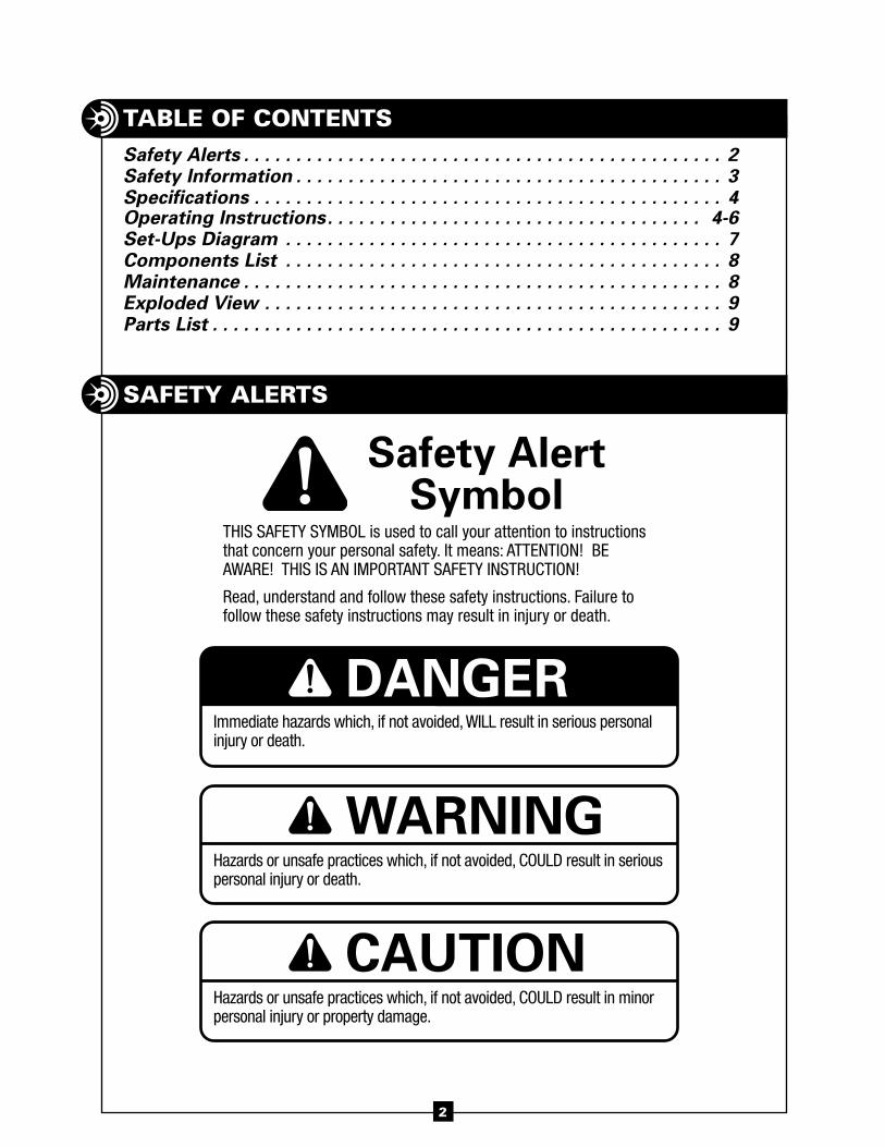
Safety AlertSymbol
This safeTy symbol is used to call your attention to instructions that concern your personal safety. it means: aTTenTion! be aware! This is an imporTanT safeTy insTrucTion!
read, understand and follow these safety instructions. failure to follow these safety instructions may result in injury or death.
DANGER
WARNING
CAUTION
immediate hazards which, if not avoided, will result in serious personalinjury or death.
hazards or unsafe practices which, if not avoided, coulD result in seriouspersonal injury or death.
hazards or unsafe practices which, if not avoided, coulD result in minorpersonal injury or property damage.
reTain saFeTy inForMaTion
3
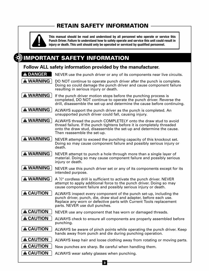
NEVER use the punch driver or any of its components near live circuits.
DO NOT continue to operate punch driver after the punch is complete. Doing so could damage the punch driver and cause component failure resulting in serious injury or death.
If the punch driver motion stops before the punching process is completed, DO NOT continue to operate the punch driver. Reverse the drill, disassemble the set-up and determine the cause before continuing.
ALWAYS support the punch driver as the punch is completed. An unsupported punch driver could fall, causing injury.
ALWAYS thread the punch COMPLETELY onto the draw stud to avoid thread failure. If the punch tightens before it is completely threaded onto the draw stud, disassemble the set-up and determine the cause. Then reassemble the set-up.
NEVER attempt to exceed the punching capacity of this knockout set. Doing so may cause component failure and possibly serious injury or death.
NEVER attempt to punch a hole through more than a single layer of material. Doing so may cause component failure and possibly serious injury or death.
NEVER use this punch driver set or any of its components except for its intended purpose.
A 1⁄2" cordless drill is sufficient to activate the punch driver. NEVER attempt to apply additional force to the punch driver. Doing so may cause component failure and possibly serious injury or death.
ALWAYS inspect every component of the punch set-up, including the punch driver, punch, die, draw stud and adapter, before each use. Replace any worn or defective parts with Current Tools replacement parts. NEVER use dull punches.
NEVER use any component that has worn or damaged threads.
ALWAYS check to ensure all components are properly assembled before punching.
ALWAYS be aware of pinch points while operating the punch driver. Keep hands away from punch and die during punching operation.
ALWAYS keep hair and loose clothing away from rotating or moving parts.
New punches are sharp. Be careful when handling them.
ALWAYS wear safety glasses when punching.
iMPorTanT saFeTy inForMaTion
Follow ALL safety information provided by the manufacturer.
WARNING
DANGER
CAUTION
WARNING
DANGER
CAUTIONWARNING
DANGER
CAUTIONWARNING
DANGER
CAUTIONWARNING
DANGER
CAUTIONWARNING
DANGER
CAUTIONWARNING
DANGER
CAUTIONWARNING
DANGER
CAUTIONWARNING
DANGER
CAUTION
WARNING
DANGER
CAUTIONWARNING
DANGER
CAUTIONWARNING
DANGER
CAUTION
This manual should be read and understood by all personnel who operate or service this Punch Driver. Failure to understand how to safely operate and service this unit could result in injury or death. This unit should only be operated or serviced by qualified personnel.
WARNING
DANGER
CAUTIONWARNING
DANGER
CAUTIONWARNING
DANGER
CAUTIONWARNING
DANGER
CAUTION
4
B E n D I n g
B E n D I n g
continued on next page . . .
oPeraTinG insTruCTions
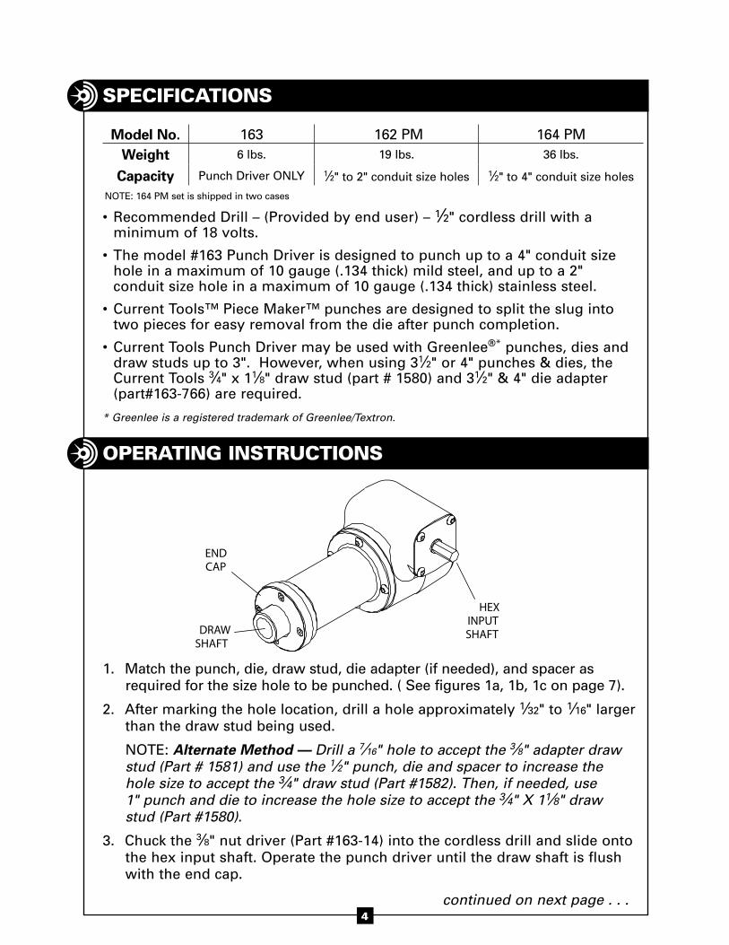
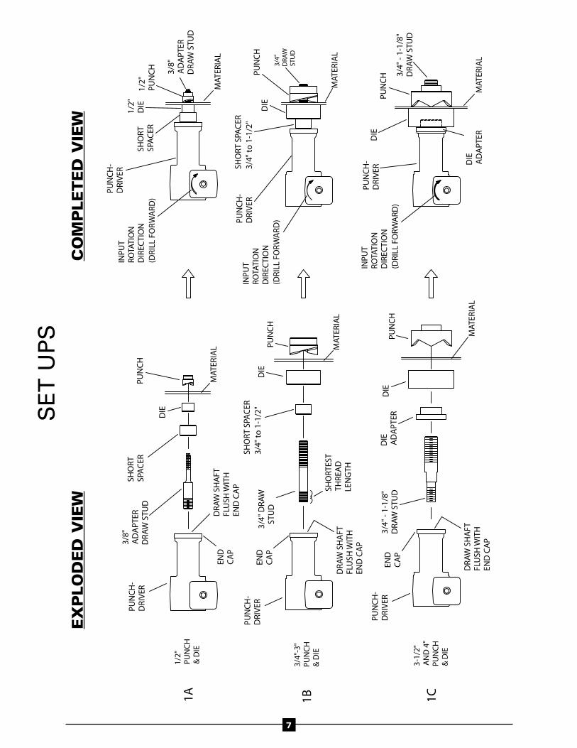
1. Match the punch, die, draw stud, die adapter (if needed), and spacer as required for the size hole to be punched. ( See figures 1a, 1b, 1c on page 7).
2. After marking the hole location, drill a hole approximately 1⁄32" to 1⁄16" larger than the draw stud being used.
NOTE: Alternate Method — Drill a 7⁄16" hole to accept the 3⁄8" adapter draw stud (Part # 1581) and use the 1⁄2" punch, die and spacer to increase the hole size to accept the 3⁄4" draw stud (Part #1582). Then, if needed, use 1" punch and die to increase the hole size to accept the 3⁄4" X 11⁄8" draw stud (Part #1580).
3. Chuck the 3⁄8" nut driver (Part #163-14) into the cordless drill and slide onto the hex input shaft. Operate the punch driver until the draw shaft is flush with the end cap.
Model No. 163 162 PM 164 PMWeight 6 lbs. 19 lbs. 36 lbs.
Capacity Punch Driver ONLY 1⁄2" to 2" conduit size holes 1⁄2" to 4" conduit size holes
NOTE: 164 PM set is shipped in two cases
sPeCiFiCaTions
• Recommended Drill – (Provided by end user) – 1⁄2" cordless drill with a minimum of 18 volts.
• The model #163 Punch Driver is designed to punch up to a 4" conduit size hole in a maximum of 10 gauge (.134 thick) mild steel, and up to a 2" conduit size hole in a maximum of 10 gauge (.134 thick) stainless steel.
• Current Tools™ Piece Maker™ punches are designed to split the slug into two pieces for easy removal from the die after punch completion.
• Current Tools Punch Driver may be used with Greenlee®* punches, dies and draw studs up to 3". However, when using 31⁄2" or 4" punches & dies, the Current Tools 3⁄4" x 11⁄8" draw stud (part # 1580) and 31⁄2" & 4" die adapter (part#163-766) are required.
* Greenlee is a registered trademark of Greenlee/Textron.
HEXINPUT SHAFTDRAW
SHAFT
ENDCAP
5
4. When using the 1⁄2" punch and die, thread the larger end of the 3⁄8" adapter draw stud (Part #1581) into the draw shaft of the punch driver until snug. (See Figure 1A on page 7.)
When using 3⁄4" through 3" punch and die, thread the end of the 3⁄4" draw stud (Part #1582) with the shortest thread length into the draw shaft of the punch driver until snug. (See Figure 1B on page 7.)
When using the 31⁄2" and 4" punch and die, thread the 3⁄4" X 11⁄8" draw stud (Part #1580) into the draw shaft of the Punch Driver until snug. (See Figure 1C on Page 7). Then slide the die adapter (Part #163-766) over the 3⁄4" X 11⁄8" draw stud until it rests on top of the end cap.
5. Slide the die onto the draw stud with the open end of the die facing away from the punch driver.
6. Place the draw stud through the hole you drilled in step 2. Then thread the punch onto the draw stud with the cutting face toward the material to be punched. Thread the punch onto the draw stud until the punch and die are snug against the material.
7. Complete the punching process by attaching the 1⁄2" cordless drill with nut driver (minimum 18 volts recommended) to the hex input shaft of the punch driver.
— Operate the drill in FORWARD to complete the punch. — After the punch is completed, run the drill in REVERSE until the draw
shaft is at least flush with the end cap. — After unloading slug, return the draw shaft until it is flush with the end
cap. NOTE: Whether to operate your drill in low or high gear will be determined
by hole size, thickness and type of material to be punched, battery strength and voltage of your drill.
oPeraTinG insTruCTions continued . . .
WARNINGALWAYS thread the punch COMPLETELY onto the draw stud to avoid thread failure. If the punch tightens before it is completely threaded onto the draw stud, disassemble the set-up and determine the cause. Then reassemble the set-up.
6
oPeraTinG insTruCTions continued . . .
CAUTIONALWAYS be aware of pinch points while operating the punch driver. Keep hands away from punch and die during punching operation.
WARNING• DO NOT continue to operate punch driver after the punch is complete. Doing so could damage
the punch driver and cause component failure resulting in serious injury or death.
• If the punch driver motion stops before the punching process is completed, DO NOT continue to operate the punch driver. Reverse the drill, disassemble the set-up and determine the cause before continuing.
• ALWAYS support the punch driver as the punch is completed. An unsupported punch driver could fall, causing injury.
7
PUN
CH
-D
RIV
ER
PUN
CH
-D
RIV
ER
3-1/
2"
AN
D 4
"PU
NC
H&
DIE
1C1A1/
2"PU
NC
H&
DIE
3/4"
-3"
PUN
CH
& D
IE1B
INPU
TR
OTA
TIO
ND
IREC
TIO
N(D
RILL
FO
RW
ARD
)
PUN
CH
-D
RIV
ER3/
4" -
1-1/
8"
DR
AW
STU
DD
IEPU
NC
H
PUN
CH
-D
RIV
ER
DIE
1/2"
DIE
MAT
ERIA
L
PUN
CH
MAT
ERIA
L
SHO
RTES
TTH
REA
D
LEN
GTH
3/4"
DR
AW
S
TUD
DIE
INPU
TR
OTA
TIO
ND
IREC
TIO
N(D
RILL
FO
RW
ARD
)PUN
CH
-D
RIV
ER
PUN
CH
3/8"
A
DA
PTER
D
RA
W S
TUD
DIE
INPU
TR
OTA
TIO
ND
IREC
TIO
N(D
RILL
FO
RW
ARD
)SH
OR
TSP
AC
ER
PUN
CH
-D
RIV
ER
3/8"
AD
APT
ERD
RA
W S
TUD
3/4"
DR
AW
STU
D
MAT
ERIA
L
PUN
CH
MAT
ERIA
L
1/2"
PUN
CH
MAT
ERIA
L
SHO
RT S
PAC
ER
3/4"
to
1-1
/2"
SHO
RTSP
AC
ER
SHO
RT S
PAC
ER
3/4"
to
1-1
/2"
DIE
A
DA
PTER
3/4"
- 1-
1/8"
D
RA
W S
TUD
DR
AW
SH
AFT
FLU
SH W
ITH
END
CA
P
END
CA
P
END
CA
P
END
CA
P
DR
AW
SH
AFT
FLU
SH W
ITH
END
CA
P
DR
AW
SH
AFT
FLU
SH W
ITH
END
CA
P
DIE
MAT
ERIA
L
PUN
CH
DIE
AD
APT
ER
SE
T U
PS
e
xP
lo
De
D v
iew
Co
MP
le
Te
D v
iew
8
CoMPonenTs lisT
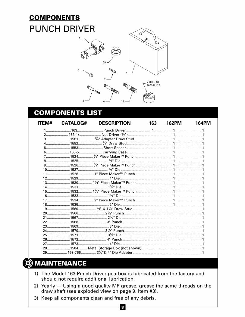
ITEM# CATALOG# DESCRIPTION 163 162PM 164PM 1 .........................163 ..........................Punch Driver .........................1 .................. 1 .......................... 1 2 ......................163-14 .....................Nut Driver (3⁄8") ............................................ 1 .......................... 1 3 ........................1581 .................3⁄8" Adapter Draw Stud ...................................... 1 .......................... 1 4 ........................1582 ........................ 3⁄4" Draw Stud ............................................. 1 .......................... 1 5 ........................1553 .........................Short Spacer .............................................. 1 .......................... 1 6 .......................163-5 .......................Carrying Case ............................................. 1 .......................... 1 7 ........................1524 ............... 1⁄2" Piece Maker™ Punch .................................... 1 .......................... 1 8 ........................1525 .............................. 1⁄2" Die ................................................... 1 .......................... 1 9 ........................1526 ............... 3⁄4" Piece Maker™ Punch .................................... 1 .......................... 1 10 .......................1527 .............................. 3⁄4" Die ................................................... 1 .......................... 1 11 .......................1528 ................1" Piece Maker™ Punch ..................................... 1 .......................... 1 12 .......................1529 ...............................1" Die .................................................... 1 .......................... 1 13 .......................1530 ..............11⁄4" Piece Maker™ Punch ................................... 1 .......................... 1 14 .......................1531 ............................. 11⁄4" Die .................................................. 1 .......................... 1 15 .......................1532 ..............11⁄2" Piece Maker™ Punch ................................... 1 .......................... 1 16 .......................1533 ............................. 11⁄2" Die .................................................. 1 .......................... 1 17 .......................1534 ................2" Piece Maker™ Punch ..................................... 1 .......................... 1 18 .......................1535 ...............................2" Die .................................................... 1 .......................... 1 19 .......................1580 .................. 3⁄4" X 11⁄8" Draw Stud .................................................................... 1 20 .......................1566 ...........................21⁄2" Punch ............................................................................. 1 21 .......................1567 ............................. 21⁄2" Die ............................................................................... 1 22 .......................1568 ............................ 3" Punch ............................................................................... 1 23 .......................1569 ...............................3" Die ................................................................................. 1 24 .......................1570 ...........................31⁄2" Punch ............................................................................. 1 25 .......................1571 ............................. 31⁄2" Die ............................................................................... 1 26 .......................1572 ............................ 4" Punch ............................................................................... 1 27 .......................1573 ...............................4" Die ................................................................................. 1 28 .......................1504 ......... Metal Storage Box (not shown)............................................................ 1 29 ....................163-766 ............... 31⁄2"& 4" Die Adapter .................................................................... 1
CoMPonenTs
PUNCH DRIVER
MainTenanCe
4 193
56
1
7 THRU 18 20 THRU 27
2
29
1) The Model 163 Punch Driver gearbox is lubricated from the factory and should not require additional lubrication.
2) Yearly — Using a good quality MP grease, grease the acme threads on the draw shaft (see exploded view on page 9. Item #3).
3) Keep all components clean and free of any debris.
1210
1
11
8
2
7
6
9
4
3
5
13
1415
16
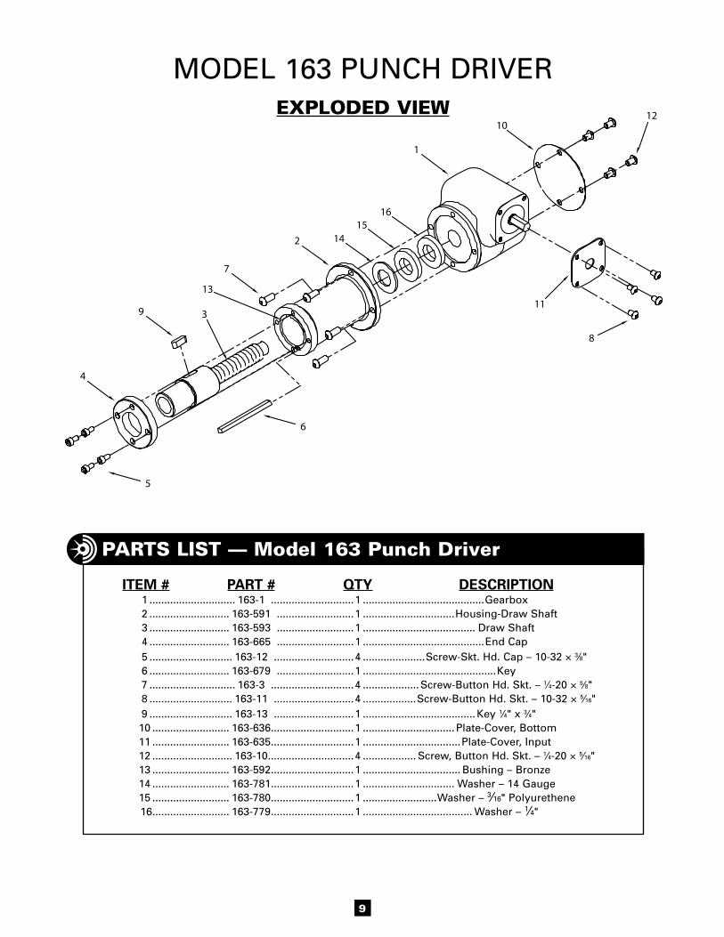
MODEL 163 PUNCH DRIVERexPloDeD view
B E n D I n gParTs lisT — Model 163 Punch Driver
ITEM # PART # QTY DESCRIPTION 1 ............................. 163-1 ............................1 .........................................Gearbox 2 ........................... 163-591 ..........................1 ...............................Housing-Draw Shaft 3 ........................... 163-593 ..........................1 ...................................... Draw Shaft 4 ........................... 163-665 ..........................1 .........................................End Cap 5 ............................ 163-12 ...........................4 .....................Screw-Skt. Hd. Cap – 10-32 × 3⁄8" 6 ........................... 163-679 ..........................1 .............................................Key 7 ............................. 163-3 ............................4 ...................Screw-Button Hd. Skt. – 1⁄4-20 × 5⁄8" 8 ............................ 163-11 ...........................4 ..................Screw-Button Hd. Skt. – 10-32 × 5⁄16" 9 ............................ 163-13 ...........................1 ......................................Key 1⁄4" x 3⁄4" 10 .......................... 163-636 ............................1 ............................... Plate-Cover, Bottom 11 .......................... 163-635 ............................1 .................................Plate-Cover, Input 12 ........................... 163-10 .............................4 .................. Screw, Button Hd. Skt. – 1⁄4-20 × 5⁄16" 13 .......................... 163-592 ............................1 ................................. Bushing – Bronze 14 .......................... 163-781 ............................1 ............................... Washer – 14 Gauge 15 .......................... 163-780 ............................1 .........................Washer – 3⁄16" Polyurethene 16 .......................... 163-779 ............................1 ..................................... Washer – 1⁄4"
9