CT542 – Host to Netowork Ethernet, WiFi, Token Ring.
37
CT542 – Host to Netowork Ethernet, WiFi, Token Ring
-
Upload
allyson-sparks -
Category
Documents
-
view
222 -
download
0
Transcript of CT542 – Host to Netowork Ethernet, WiFi, Token Ring.
CT542 – Host to Netowork
Ethernet, WiFi, Token Ring
Contents
• Ethernet– Classical Ethernet (cabling, encoding, frame format,
channel access protocol)– Switched Ethernet– Fast Ethernet– Gigabit Ethernet
• Wireless LANs
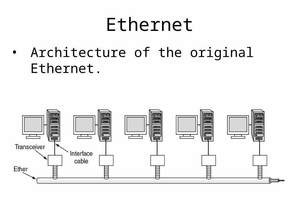
Ethernet
• Architecture of the original Ethernet.

Ethernet Cabling
The most common kinds of Ethernet cabling.
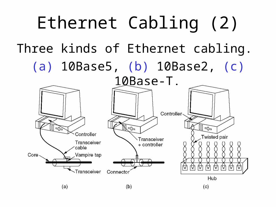
Ethernet Cabling (2)
Three kinds of Ethernet cabling.
(a) 10Base5, (b) 10Base2, (c) 10Base-T.
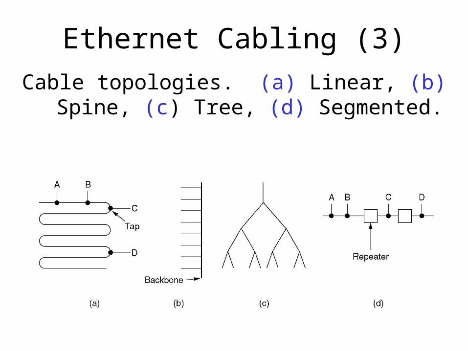
Ethernet Cabling (3)
Cable topologies. (a) Linear, (b) Spine, (c) Tree, (d) Segmented.
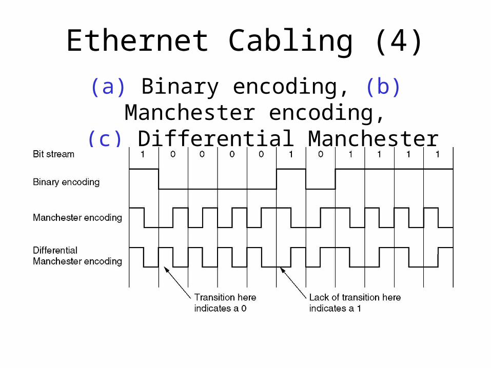
Ethernet Cabling (4)
(a) Binary encoding, (b) Manchester encoding, (c) Differential Manchester encoding.

Ethernet MAC Sublayer Protocol (1)
Frame formats. (a) DIX Ethernet, (b) IEEE 802.3.
Each frame starts with Preamble of 8 bytes, each containing the bit pattern 10101010. The Manchester encoding on this pattern produces a 10MHz square wave for 6.4 us to allow the receiver's clock to synchronize with the sender. The clock will stay in sync for the rest of the frame, using the transitions in the middle of the bit boundaries for adjustment. IEEE 802.3 is using a 7 bytes preamble and 1 byte start of frame (SOF)
Frame continues with two address fields. 6 byte addresses for destination and source are used. The high order bit is 0 for normal addresses and 1 for group addresses. The address with all 1 is reserved for broadcast. Second high order bit is 1 if the address is local or 0 if the address is global. 46 bits available for address space (about 70T unique addresses are possible). The idea is that any station can address other station by giving the 48 bit number
Type field in DIX: - tells to the receiver what to do with the frame. Multiple network protocols could be supported. So this field is unique for each network protocol. It is used to dispatch the incoming frames. IEEE 802.3 changed the type field in Length field – the type is handled as part of the data itself, in a small header. The length field contains the length in bytes of the data, up to 1500 bytes.
Data, up to 1500 bytes. This limit was chosen arbitrarily at the time DIX was released. It was based on the fact that a transceiver needed enough RAM to hold an entire data frame and RAM was expensive back in 1978.
There is also a minimum frame length, related to the collision detection. The explanation is given in the next slide. The minimum Ethernet frame length is 64 bytes (without the preamble), and if the data portion is less than 46 bytes (64 – headers + checksum) then the PAD field is used to fill the frame to the minimum size.
Checksum is a 32 bit hash code of the data, computed with a CRC algorithm, having a 32 order generator polynomial. It just does error detection, no forward error correction.

Ethernet MAC Sublayer Protocol (2)
Collision detection can take as long as 2 .
Binary Exponential Backoff Algorithm• After a collision the time is divided in discrete slots (equal to
worst round trip propagation, which is 512 bits time or 51.2 us)• After the first collision, each station waits 0 or 1 slot time before
tries again– If two station collide and they pick same number, they will collide again
• After a second collision, each station waits 0, 1, 2 or 3 at random and waits that number of slot times.
• After a third collision will happen, the next number to pick is between 0 and 23 -1 and that number of slots is skipped.
• After 10 collisions have been reached, the number interval is frozen at 0 – 1023.
• After 16 collisions, the station gives up to send the frame and reports the failure. Further recovery it is up to the higher layers.
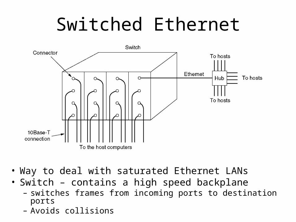
Switched Ethernet
• Way to deal with saturated Ethernet LANs• Switch – contains a high speed backplane
– switches frames from incoming ports to destination ports– Avoids collisions
Fast Ethernet
• Approved as IEEE 802.3 u standard in 1995
• Keeps all the old frame formats, interfaces and procedural rules
• Reduces the bit time from 100ns to 10ns
• It is based only on the 10Base-T wiring– It is using only hubs and switches; drop cables with
vampire taps and BNC connectors are not possible
• It supports both UTP Cat 3 (for backwards compatibility with preinstalled infrastructure) and UTP Cat 5 cables

Fast Ethernet - Cabling
The original fast Ethernet (802.3u) cabling.
Fast Ethernet – 100Base-TX (1)• Is using only two pairs out of the 4 available in the UTP
cable (one for transmit and one for receive)• For 100 Mbps, the waveform frequency would peak at
50MHz, while with Manchester encoding would pick at 100MHz – Category 5 UTP is only rated at 100MHz, so Fast Ethernet
would be difficult to implement using Manchester encoding
• 100BASE-TX uses two encoding techniques:– 4B/5B coding schema is used to avoid loss of synchronization
– To decrease the frequency on UTP cable, MLT-3 (Multiple Level Transition - 3 levels) encoding is used

Fast Ethernet –100Base-TX (2)
• In order to send information using 4B5B encoding, the data byte to be sent is first broken into two nibbles. – If the byte is 0E, the first nibble is 0 and the second nibble is E.
• Next each nibble is remapped according to the 4B5B table– Hex 0 is remapped to the 4B5B code 11110. – Hex E is remapped to the 4B5B code 11100.
• The 4B5B replacement happens at the Physical layer, followed by MLT-3 encoding
• 4B5B Encoding Table:
Data Binary 4B/5B code
0 0000 11110
1 0001 01001
2 0010 10100
…
E 1110 11100
F 1111 11101
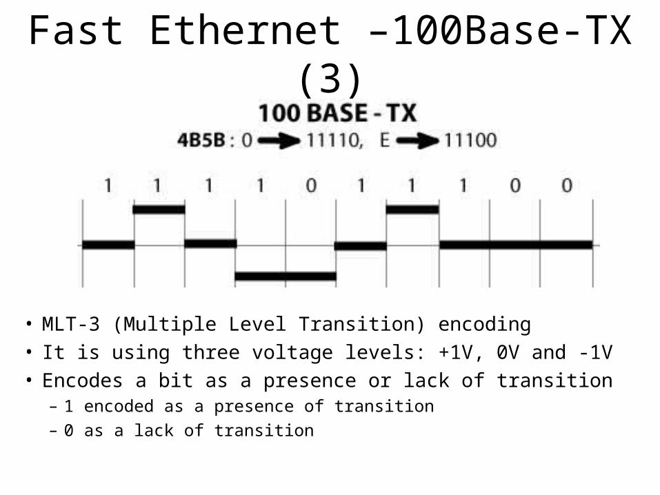
Fast Ethernet –100Base-TX (3)
• MLT-3 (Multiple Level Transition) encoding• It is using three voltage levels: +1V, 0V and -1V• Encodes a bit as a presence or lack of transition
– 1 encoded as a presence of transition
– 0 as a lack of transition
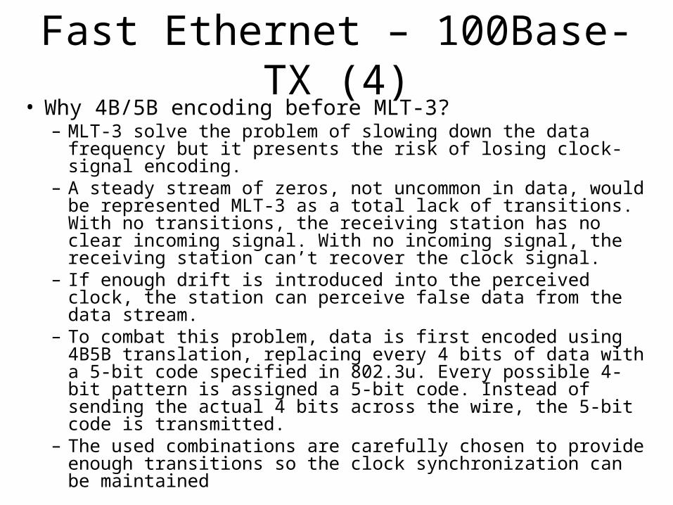
Fast Ethernet – 100Base-TX (4)• Why 4B/5B encoding before MLT-3?
– MLT-3 solve the problem of slowing down the data frequency but it presents the risk of losing clock-signal encoding.
– A steady stream of zeros, not uncommon in data, would be represented MLT-3 as a total lack of transitions. With no transitions, the receiving station has no clear incoming signal. With no incoming signal, the receiving station can’t recover the clock signal.
– If enough drift is introduced into the perceived clock, the station can perceive false data from the data stream.
– To combat this problem, data is first encoded using 4B5B translation, replacing every 4 bits of data with a 5-bit code specified in 802.3u. Every possible 4-bit pattern is assigned a 5-bit code. Instead of sending the actual 4 bits across the wire, the 5-bit code is transmitted.
– The used combinations are carefully chosen to provide enough transitions so the clock synchronization can be maintained
Fast Ethernet – 100BaseT4
• Is using all 4 pairs available in the UTP Cat 3 cable (one for transmit, one for receive and two that are switch-able with the data flow)
• Cat 3 UTP cable can handle only about 16MHz signal– With encoding techniques used over Cat 5 cable, this
is not enough to carry 31.25MHz signal.
• It is using a coding technique known as 8B/6T

Fast Ethernet – 100BaseT4 (2)• In order to send information using 8B6T encoding, the
value of the data byte is converted to the values in the 8B6T table. – Every possible byte has a unique 6T code, a set of 6 tri-state
symbols.
– Unlike 4B5B, 8B6T completely prepares the data for transmission; no further encoding is required.
• 100BASE-T4 is currently the only technology which uses 8B6T encoding. It performs 8B6T encoding at the Physical layer.
• 100BASE-T4 then de-multiplexes the 6T codes onto three wire pairs.
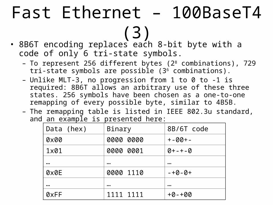
Fast Ethernet – 100BaseT4 (3)• 8B6T encoding replaces each 8-bit byte with a code of only 6 tri-
state symbols. – To represent 256 different bytes (28 combinations), 729 tri-state symbols
are possible (36 combinations). – Unlike MLT-3, no progression from 1 to 0 to -1 is required: 8B6T allows
an arbitrary use of these three states. 256 symbols have been chosen as a one-to-one remapping of every possible byte, similar to 4B5B.
– The remapping table is listed in IEEE 802.3u standard, and an example is presented here:
Data (hex) Binary 8B/6T code
0x00 0000 0000 +-00+-
1x01 0000 0001 0+-+-0
… … …
0x0E 0000 1110 -+0-0+
… … …
0xFF 1111 1111 +0-+00

Fast Ethernet – 100BaseT4 (4)• The fastest waveform required in 8B6T is alternating extreme
states, +1 to -1, encoding two tri-state symbols in a single wavelength. Unlike 4B5B, the carrier wave frequency only needs to be 3/4 the speed of the bit stream, as only 6 signals are used to communicate 8 bits.
• The fastest possible waveform base frequency is 37.5MHz (3/4 * 50MHz – max base frequency in a binary signal for a 010101… pattern), which is still too fast for UTP-3, so one more technique is needed – de-multiplexing data on three separate channels
• The final slowdown in 8B6T comes from fanning the transmitted signal out to three cable pairs instead of a single pair. This is called "T4 Multiplexing"
• The maximum speed waveform required is now only 12.5 MHz, slow enough for even Category 3 twisted pair (which has a limit of 16MHz).

Fast Ethernet – 100BaseT4(5)
• Data is transmitted by the Ethernet card and de-multiplexed out onto three pairs of the Category 3 Cable.
• Bytes are multiplexed at the receiving end and placed back in the correct order. The fourth pair of the wire is used for collision detection.
• In this way, each wire only has to carry 33.3 Mbps, for an aggregate throughput of 100 Mbps. This is how 100 Mbps Ethernet can run on Category 3 unshielded twisted-pair cable

Fast Ethernet – 100BaseFX (1)
• Is using optical fiber
• 100BASE-FX uses two encoding techniques:– 4B/5B coding schema is used to avoid loss of
synchronization– NRZI (Non-Return-To-Zero, Invert-on-one) encoding
is used
• The distance between a station and a hub can be up to 2 KM.
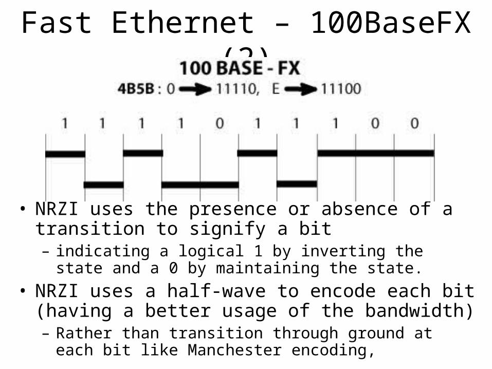
Fast Ethernet – 100BaseFX (2)
• NRZI uses the presence or absence of a transition to signify a bit – indicating a logical 1 by inverting the state and a 0 by
maintaining the state.
• NRZI uses a half-wave to encode each bit (having a better usage of the bandwidth)– Rather than transition through ground at each bit like
Manchester encoding,
Gigabit Ethernet (1)• IEEE 802.3z approved in 1998• All configurations are point to point rather than
multidrop as in classical Ethernet• Supports two modes of operation:
– Full Duplex mode (the normal mode of operation)• All the stations are connected through a switch that allows traffic in
both directions at the same time• CSMA/CD is not employed anymore• Max cable length is governed by propagation issues
– Half duplex mode• All stations are connected through a hub, that internally electrically
connects all the lines, simulating a multidrop environment as with classic Ethernet electrically connects all the lines
• CSMA/CD protocol is required• Max cable length is still governed by CSMA/CD protocol
Gigabit Ethernet (2)
• Half Duplex Mode Max Cable length extended using:– Carrier extension
• Hardware adds its own padding to extend the frame to 512 bytes; since this padding is added by sending hardware and removed by the receiving hardware, the software is not aware of it
– Frame Bursting• Allows the sender to transmit a concatenated sequence of multiple
frames in one single transmission; if the total length of burst is less then 512 bytes, the hardware pads it again.
• Those techniques extend the radius of the network to 200 meters
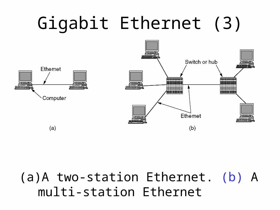
Gigabit Ethernet (3)
(a) A two-station Ethernet. (b) A multi-station Ethernet

Gigabit Ethernet (4)
Gigabit Ethernet cabling.

Wireless LANs (1)
• (a) Wireless networking with a base station.• (b) Ad hoc networking.
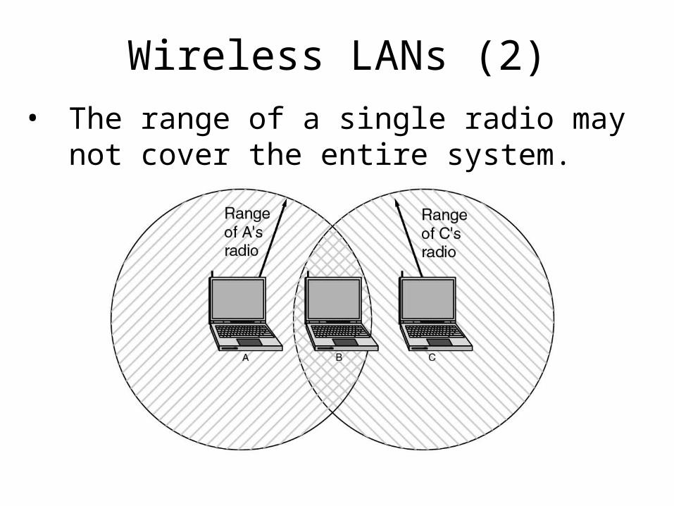
Wireless LANs (2)
• The range of a single radio may not cover the entire system.
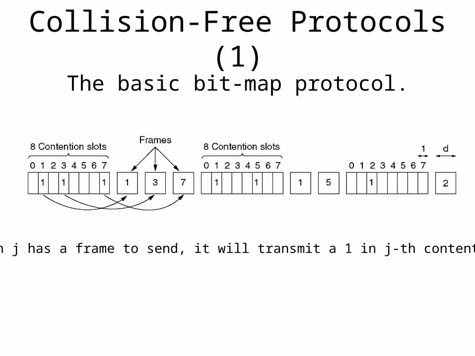
Collision-Free Protocols (1)
The basic bit-map protocol.
If station j has a frame to send, it will transmit a 1 in j-th contention slot
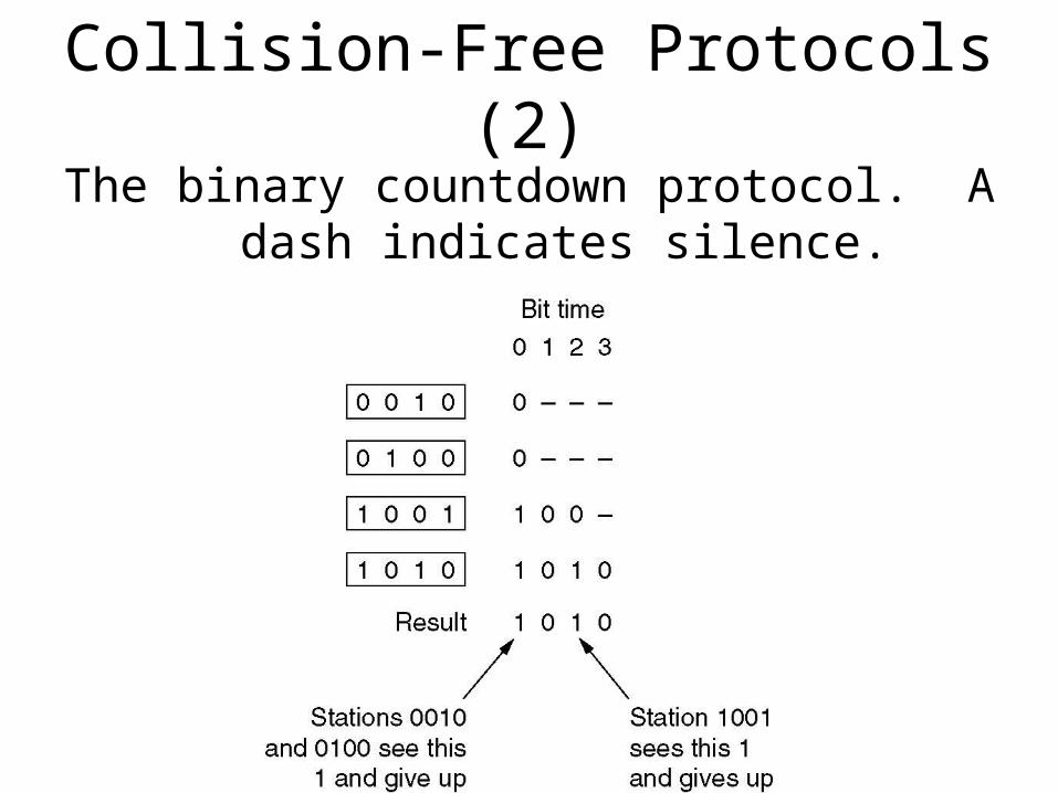
Collision-Free Protocols (2)
The binary countdown protocol. A dash indicates silence.
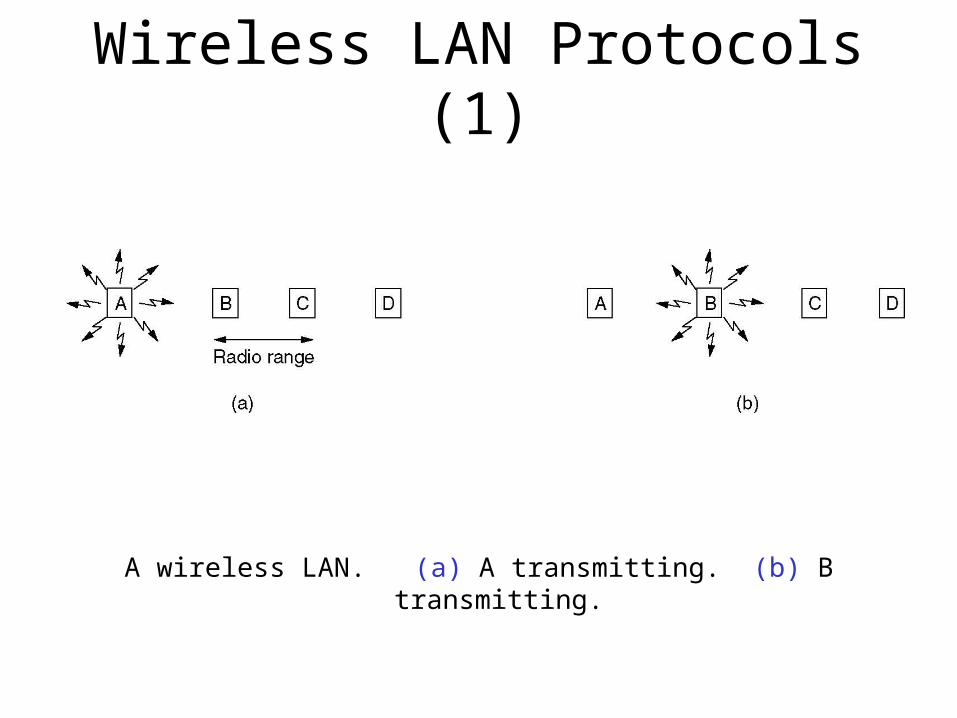
Wireless LAN Protocols (1)
A wireless LAN. (a) A transmitting. (b) B transmitting.
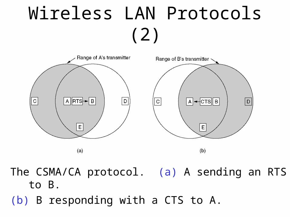
Wireless LAN Protocols (2)
The CSMA/CA protocol. (a) A sending an RTS to B.
(b) B responding with a CTS to A.
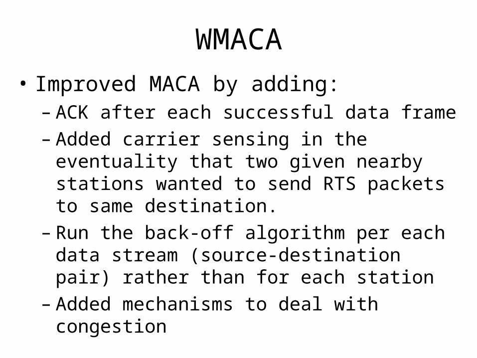
WMACA
• Improved MACA by adding:– ACK after each successful data frame– Added carrier sensing in the eventuality that two
given nearby stations wanted to send RTS packets to same destination.
– Run the back-off algorithm per each data stream (source-destination pair) rather than for each station
– Added mechanisms to deal with congestion

Wireless LANs (3)
• A multicell 802.11 network (ETH & WiFi).
References
• Andrew S. Tanenbaum – Computer Networks, ISBN 0-13-066102-3