CSC-103 Line Protection IED Product Guide V1.11 2013-12-31 Line... · IED ins sta Ov Communic...
70
CSC-103 Line Protection IED Product Guide
Transcript of CSC-103 Line Protection IED Product Guide V1.11 2013-12-31 Line... · IED ins sta Ov Communic...

CSC-103Line Protection IED
Product Guide

Note: Th
the instr
correspo
he company
ruction at a
onding servi
We rescommedissem
This doasked t
The dadeemeconstanas a reproduc
ManufaBeijing
Tel: +8Fax: +8Email: Websit
Add: N
y keeps the
anywhere, p
ice.
®
serve all rightsercial propriet
mination to third
ocument has bto notify us as
ata contained d to be a stantly seek to en
esult; it is possct and this info
acturer: Sifang Autom
86 10 629625586 10 8278362sf_sales@sf-a
te: http://www.
o.9, Shangdi 4
Copy
right to perf
lease conta
is registered
s to this documtary right is d parties, is no
been carefullys soon as poss
in this manuaatement of gunsure that our sible that therrmation produ
mation Co., Ltd
54, +86 10 62925 auto.com sf-auto.com
4th Street, Ha
yright owne
fect the inst
act our com
d trademark o
ment, even in tregistered. Im
ot permitted.
y checked. If tsible.
al is intended uaranteed pro
products are re may be somuct.
d.
961515 ext. 89
aidian District,
D
er: Beijing S
truction. If e
mpany in tim
of Beijing Sifan
the event thatmproper use,
the user neve
solely for theperties. In thedeveloped to
me differences
998
Beijing, P.R.C
Doc. Code:
Issued
Sifang Auto
quipments d
me. We will
ng Automation
t a patent is is, in particula
ertheless detec
IED descripte interests of the latest techs between the
C.100085
Version:V
: 0SF.492.0
d Date:20
omation Co
do not agree
provide you
n Co., Ltd.
ssued and a diar reproductio
cts any errors
tion and is nof our customehnological stane hardware/so
V1.11
051(E)
13.12
o., Ltd
e with
u with
ifferent on and
s, he is
t to be ers, we ndards oftware

CSC
spee
prote
Devic
comb
for fo
O
v
T
A
1
a
E
S
H
S
th
.
C-103 is se
ed compre
ection IED
ce) for ov
bination of t
ollowing app
Overhead lin
voltage leve
Two and thre
All type of st
.5 breakers
arrangemen
Extremely lo
Short lines
Heavily load
Satisfy the re
hree pole tr
elective, re
hensive tra
D (Intellig
verhead lin
them. It is a
plications:
nes and cab
el
ee-end line
tation arran
s arrangeme
nt, etc.
ong lines
ded lines
equirement
ripping
eliable and
ansmission
gent Elect
nes, cable
a proper so
bles up to 1
s
gement, su
ent, double
t for single a
O
1
high
line
tronic
es or
lution
000kV
uch as
bus
and /or
Th
fun
me
and
sch
wit
cha
full
wh
pro
fun
com
Th
IED
ins
sta
Ov
Communic
system
e IED prov
nctions ba
easurement
d reliable
heme distan
th innovativ
aracteristic.
ly indepen
hich provid
otection for
nctions are
mplete back
e wide app
D an exce
stallations a
ations
verv
cation with s
ides line dif
ased on
with high s
phase se
nce protecti
ve and pr
Five dist
dent meas
des high
all types o
also empl
kup protecti
plication fle
ellent choic
and retrofitti
vie
station auto
fferential pr
phase-seg
sensitivity f
election. T
ion is also p
roven quad
tance zone
suring and
flexibility
of lines. Ma
loyed to pr
ion library.
exibility mak
ce for bot
ing of the e
ew
omation
rotection
gregated
for faults
The full
provided
drilateral
es have
setting
of the
ny other
rovide a
kes the
th new
existing

Feature
2
Protection and monitoring IED with
extensive functional library, user
configuration possibility and expandable
hardware design to meet with user’s
special requirements
Redundant A/D sampling channels and
interlocked dual CPU modules
guarantee the high security and
reliability of the IED
Single and/or three tripping/reclosing
Highly sensitive startup elements, which
enhance the IED sensitivity in all
disturbance conditions and avoid
maloperation
Current sudden-change startup
element
Zero sequence current startup
element
Overcurrent startup element
Undervoltage startup element for
weak-infeed end of line
Three kinds of faulty phase selectors are
combined to guarantee the correction of
phase selection:
Current sudden-change phase
selector
Zero sequence and negative
sequence phase selector
Undervoltage phase selector
Four kinds of directional elements
cooperate each other so as to determine
the fault direction correctly and promptly:
Memory voltage directional element
Zero sequence component
directional element
Negative sequence component
directional element
Impedance directional element
Line differential protection (87L):
Phase-segregated measurement
with high sensitivity
Charging current compensation
High reliability against external fault
with CT saturation detection
Automatic conversion of CT ratios
Time synchronization of sampling
Redundant communication
channels without channel switching
delay
Full scheme phase-to-phase and
phase-to-earth distance protection with
five quadrilateral protection zones and
additional extension zone characteristic
(21, 21N)
Power swing function (68)
Proven and reliable principle of
power swing logic
Unblock elements during power
swing
All useful types of tele-protection
scheme (85)
Permissive Underreach Transfer
Trip (PUTT) scheme
Permissive Overreach Transfer Trip
(POTT) scheme
Blocking scheme
Inter-tripping scheme
Particular logic for tele-protection
scheme

Feature
3
Current reversal
Weak-infeed end
Evolving fault logic
Sequence tripping logic
A complete protection functions library,
include:
Line differential protection (87L)
Distance protection with
quadrilateral characteristic
(21,21N)
Power swing function (68)
Tele-protection scheme based on
distance protection (85-21,21N)
Tele-protection scheme based on
dedicated earth fault protection
(85-67N)
Overcurrent protection (50, 51, 67)
Earth fault protection (50N, 51N,
67N)
Emergency/backup overcurrent
protection (50, 51)
Emergency/backup earth fault
protection (50N, 51N)
Switch-onto-fault protection
(50SOTF)
Overload protection (50OL)
Overvoltage protection (59)
Undervoltage protection (27)
Circuit breaker failure protection
(50BF)
Poles discordance protection
(50PD)
Dead zone protection (50DZ)
STUB protection (50STUB)
Synchro-check and energizing
check (25)
Auto-reclosing function for single-
and/or three-phase reclosing (79)
Voltage transformer secondary
circuit supervision (97FF)
Current transformer secondary
circuit supervision
Self-supervision to all modules in the
IED
Complete IED information recording:
tripping reports, alarm reports, startup
reports and general operation reports.
Any kinds of reports can be stored up to
2000 and be memorized in case of
power disconnection
Remote communication
Tele-protection contacts for power
line carrier protection interface
Up to two fiber optical remote
communication ports for protection
function, like differential protection,
distance and EF tele-protection,
used up to 100kM single–mode
optical fiber cable
External optical/electrical converter,
which support communication
through SDH or PCM, for G.703
(64kbit/s) and G.703E1 (2048kbit/s)
Up to three electric /optical Ethernet
ports can be selected to communicate
with substation automation system by
IEC61850 or IEC60870-5-103 protocols
Up to two electric RS-485 ports can be
selected to communicate with substation
automation system by IEC60870-5-103

Feature
4
protocol
Time synchronization via network
(SNTP), pulse and IRIG-B mode
Configurable LEDs (Light Emitting
Diodes) and output relays satisfied users’
requirement
Versatile human-machine interface
Multifunctional software tool for setting,
monitoring, fault recording analysis,
configuration, etc.

Function
5
Protection functions
Description ANSI Code
IEC 61850
Logical Node
Name
IEC 60617
graphical symbol
Differential protection
Line differential protection 87L PDIF
Distance protection
Distance protection 21, 21N PDIS Z<
Power-swing function 68 RPSB Zpsb
Tele-protection
Communication scheme for distance
protection 85–21,21N PSCH
Communication scheme for earth fault
protection 85–67N PSCH
Current protection
Overcurrent protection 50,51,67 PTOC
3IINV>
3I >>
3I >>>
Earth fault protection 50N, 51N, 67N PTEF
I0INV>
I0>>
I0>>>
Emergency/backup overcurrent protection 50,51 PTOC 3IINV>
3I >
Emergency/backup earth fault protection 50N,51N PTEF I0INV>
I0 >
Switch-onto-fault protection 50SOTF PSOF 3I >SOTF
I0>SOTF
Overload protection 50OL PTOC 3I >OL
Voltage protection
Overvoltage protection 59 PTOV 3U>
3U>>
Undervoltage protection 27 PTUV 3U<
3U<<
Breaker protection and control function
Circuit breaker failure protection 50BF RBRF 3I> BF

Function
6
I0>BF
I2>BF
Dead zone protection 50DZ
3I> DZ
I0>DZ
I2>DZ
STUB protection 50STUB PTOC 3I>STUB
Poles discordance protection 50PD RPLD
3I< PD
I0>PD
I2>PD
Synchro-check and energizing check 25 RSYN
Auto-reclosing 79 RREC O→I
Single- and/or three-pole tripping 94-1/3 PTRC
Secondary system supervision
CT secondary circuit supervision
VT secondary circuit supervision 97FF
Monitoring functions
Description
Redundant A/D sampling data self-check
Phase-sequence of voltage and current supervision
3I0 polarity supervision
The third harmonic of voltage supervision
Synchro-check reference voltage supervision
Auxiliary contacts of circuit breaker supervision
Broken conductor check
Self-supervision
Logicality of setting self-check
Fault locator
Fault recorder
Function
7
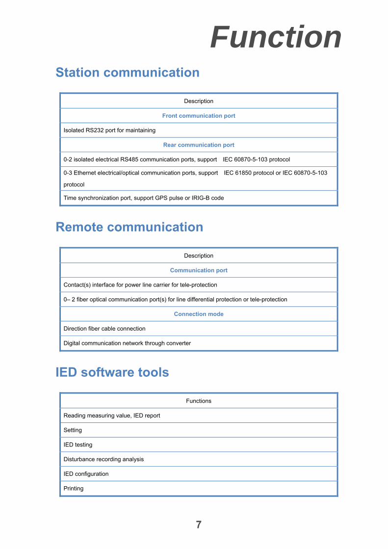
Station communication
Description
Front communication port
Isolated RS232 port for maintaining
Rear communication port
0-2 isolated electrical RS485 communication ports, support IEC 60870-5-103 protocol
0-3 Ethernet electrical/optical communication ports, support IEC 61850 protocol or IEC 60870-5-103
protocol
Time synchronization port, support GPS pulse or IRIG-B code
Remote communication
Description
Communication port
Contact(s) interface for power line carrier for tele-protection
0– 2 fiber optical communication port(s) for line differential protection or tele-protection
Connection mode
Direction fiber cable connection
Digital communication network through converter
IED software tools
Functions
Reading measuring value, IED report
Setting
IED testing
Disturbance recording analysis
IED configuration
Printing

Function
8
Protection
9
Startup elements
The startup elements basically work as
sensitive detector to all types of fault. As
soon as fault or disturbance happens, the
highly sensitive startup elements will
operate immediately and initiate all
necessary protection functions for
selective clearance of the fault.
The control circuit of tripping relays is
controlled by the startup elements. Only
when one of the startup elements is
triggered, the tripping relays can be
energized to trip. Thus, the maloperation,
due to fatal internal hardware fault, is
avoided in this way.
Based on different principle, there are four
kinds of startup elements listed below,
which are used to enhance the sensitivity,
and to guarantee the security in case of
IED’s internal hardware faults.
Sudden-change current startup element
Sudden-change phase to phase or zero
sequence current elements are the main
startup element that can sensitively detect
most of faults. The criteria are as follows:
_
or
_
where:
∆i=|| i (K) - i (K-T) | - |i (K-T) - i
(K-2T) ||
: AB,BC or CA, e.g. iAB= iA-iB
K: The present sample
T: The sample quantity of one power cycle
∆3i0: Sudden-change zero sequence current
I_Abrupt: The setting value of current
sudden-change elements
Zero sequence current startup element
Zero sequence current startup element is
applied to improve the fault detection
sensitivity at the high resistance earth
faults. As an auxiliary startup element, it
operates with a short time delay.
Overcurrent startup element
If overcurrent protection function is
enabled, overcurrent startup element is
used to improve the fault detection
sensitivity. As an auxiliary startup element,
it operates with short time delay.
Low-voltage startup element
When one end of the protected line is a
weak-source system, and the fault
sudden-change phase to phase current is
too low to startup the IED, low-voltage
startup element can be in service to startup
the tele-protection scheme with weak-echo
logic.
Phase selector
The IED applies different phase selectors
to determine the faulty phase to make
tripping or Auto-reclosing initiation
correctly. There are three kinds of phase
selectors based on different principle for
different fault stages.
Sudden-change current phase selector
It operates as soon as the sudden- change
current startup element starts up. It makes
a phase selection for fast tripping by
Protection
10
comparison amongst changes of
phase-phase currents, iAB, iBC and
iCA.
Symmetrical component phase selector
During the whole period of fault, the phase
selector checks the angle between
negative sequence current and zero
sequence current vectors to determine
faulty phases. In addition, phase to phase
faults will be discriminated through
impedance characteristic.
Low voltage phase selector
Both current sudden-change phase and
symmetric component phase selector are
not applicable for weak-infeed end of
protected line, so low-voltage phase
selector is employed in this condition
without VT failure. Theoretically, when one,
two or three phase voltages reduce, the
relevant phase(s) is selected as faulty
phase.
Directional elements
Four kinds of directional elements are
employed for reliable determination of
various faults direction. The related
protection modules, such as distance
protection, tele-protection schemes and
overcurrent and earth fault protections,
utilize the output of the directional
elements as one of their operating
condition. All the following directional
elements cooperate with the mentioned
protection functions.
Memory voltage directional element
The IED uses the memory voltage and
fault current to determine the direction of
the fault. Therefore transient voltage of
short circuit conditions doesn’t influence
the direction detection. Additionally, it
improves the direction detection sensitivity
for symmetrical or asymmetrical close-in
faults with extremely low voltage. But it
should be noted that the memory voltage
cannot be effective for a long time.
Therefore, the following directional
elements work as supplement to detect
direction correctly.
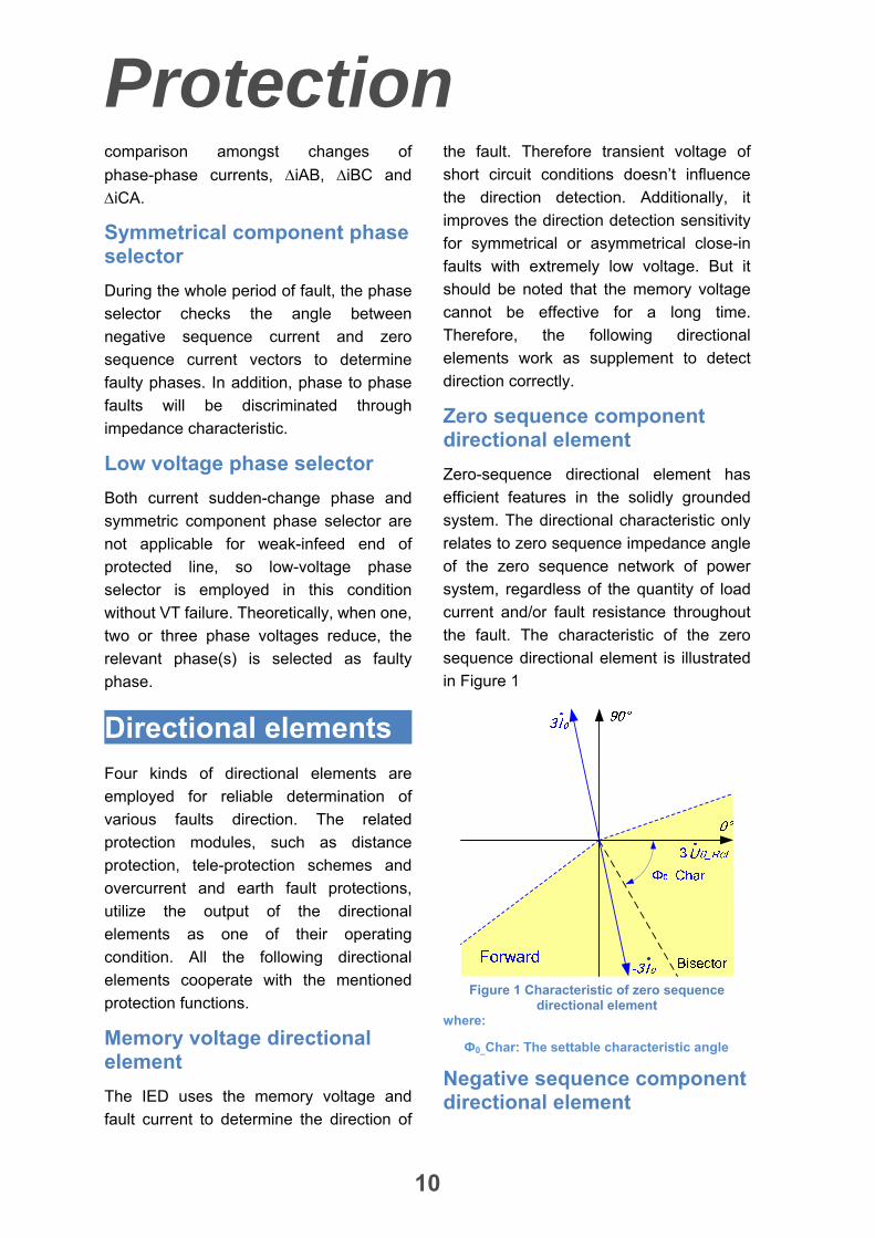
Zero sequence component directional element
Zero-sequence directional element has
efficient features in the solidly grounded
system. The directional characteristic only
relates to zero sequence impedance angle
of the zero sequence network of power
system, regardless of the quantity of load
current and/or fault resistance throughout
the fault. The characteristic of the zero
sequence directional element is illustrated
in Figure 1
Figure 1 Characteristic of zero sequence
directional element where:
Ф0_Char: The settable characteristic angle
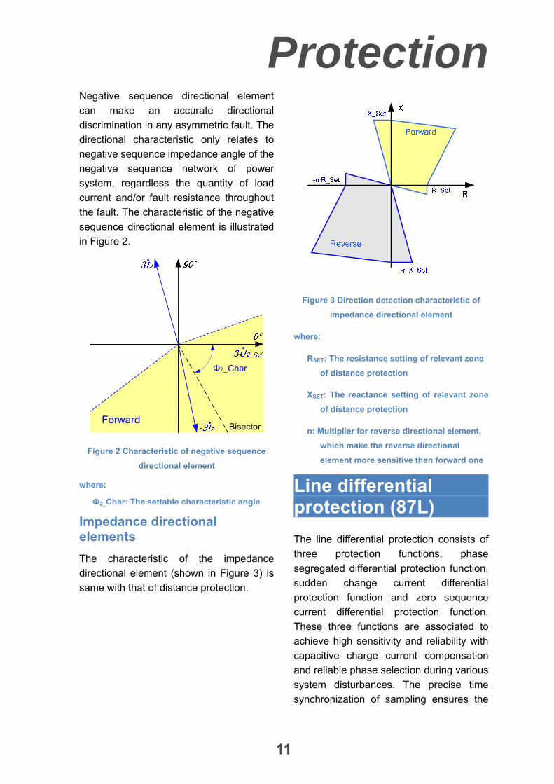
Negative sequence component directional element
Protection
11
Negative sequence directional element
can make an accurate directional
discrimination in any asymmetric fault. The
directional characteristic only relates to
negative sequence impedance angle of the
negative sequence network of power
system, regardless the quantity of load
current and/or fault resistance throughout
the fault. The characteristic of the negative
sequence directional element is illustrated
in Figure 2.
Forward
Φ2_Char
Bisector
Figure 2 Characteristic of negative sequence
directional element
where:
Ф2_Char: The settable characteristic angle
Impedance directional elements
The characteristic of the impedance
directional element (shown in Figure 3) is
same with that of distance protection.
Figure 3 Direction detection characteristic of
impedance directional element
where:
RSET: The resistance setting of relevant zone
of distance protection
XSET: The reactance setting of relevant zone
of distance protection
n: Multiplier for reverse directional element,
which make the reverse directional
element more sensitive than forward one
Line differential protection (87L)
The line differential protection consists of
three protection functions, phase
segregated differential protection function,
sudden change current differential
protection function and zero sequence
current differential protection function.
These three functions are associated to
achieve high sensitivity and reliability with
capacitive charge current compensation
and reliable phase selection during various
system disturbances. The precise time
synchronization of sampling ensures the
Protection
12
differential protection of both end IEDs to
operate reliably.
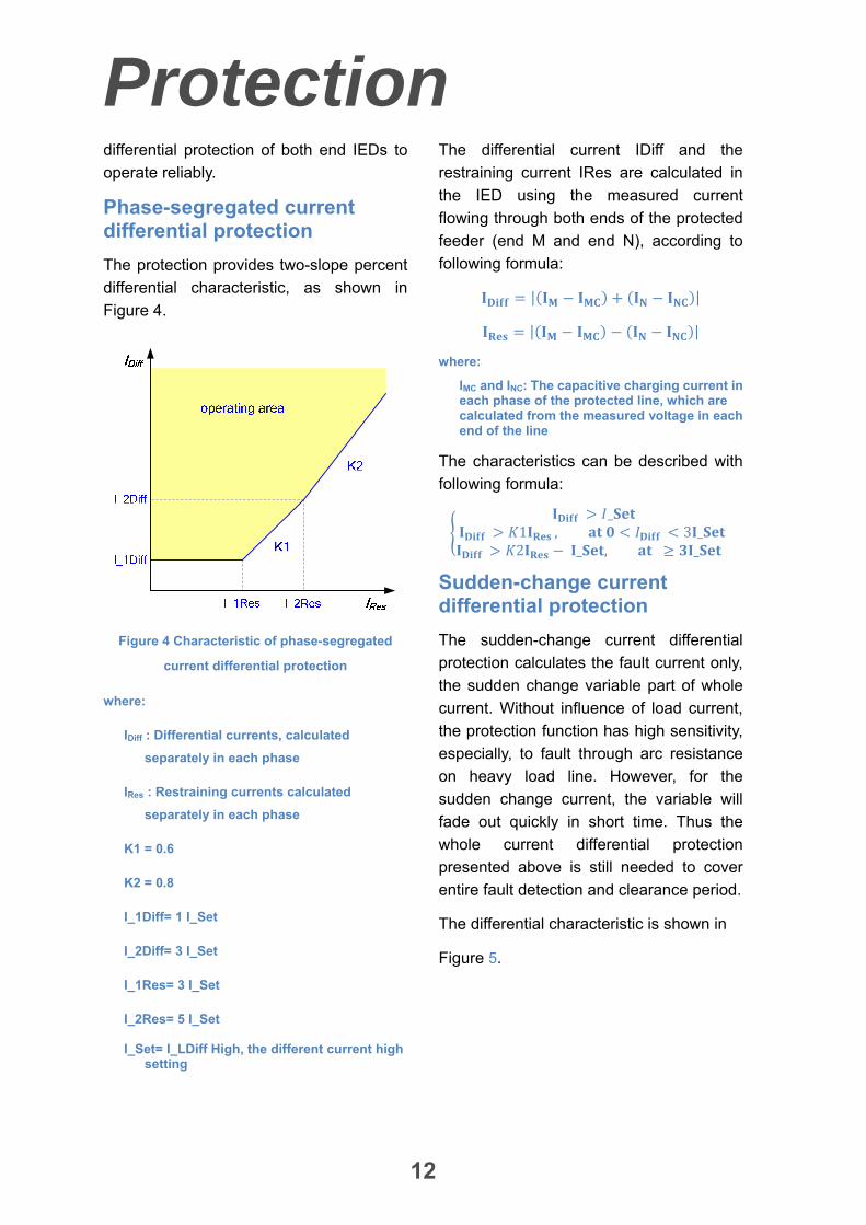
Phase-segregated current differential protection
The protection provides two-slope percent
differential characteristic, as shown in
Figure 4.
Figure 4 Characteristic of phase-segregated
current differential protection
where:
IDiff : Differential currents, calculated
separately in each phase
IRes : Restraining currents calculated
separately in each phase
K1 = 0.6
K2 = 0.8
I_1Diff= 1 I_Set
I_2Diff= 3 I_Set
I_1Res= 3 I_Set
I_2Res= 5 I_Set
I_Set= I_LDiff High, the different current high setting
The differential current IDiff and the
restraining current IRes are calculated in
the IED using the measured current
flowing through both ends of the protected
feeder (end M and end N), according to
following formula:
| |
| |
where:
IMC and INC: The capacitive charging current in each phase of the protected line, which are calculated from the measured voltage in each end of the line
The characteristics can be described with
following formula:
_ 1 , 3 _ 2 _ , _
Sudden-change current differential protection
The sudden-change current differential
protection calculates the fault current only,
the sudden change variable part of whole
current. Without influence of load current,
the protection function has high sensitivity,
especially, to fault through arc resistance
on heavy load line. However, for the
sudden change current, the variable will
fade out quickly in short time. Thus the
whole current differential protection
presented above is still needed to cover
entire fault detection and clearance period.
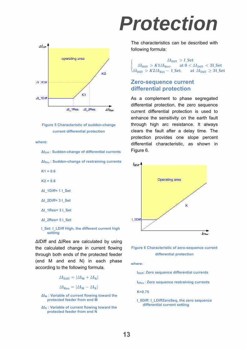
The differential characteristic is shown in
Figure 5.
Protection
13
Figure 5 Characteristic of sudden-change
current differential protection
where:
∆IDiff : Sudden-change of differential currents
∆IRes : Sudden-change of restraining currents
K1 = 0.6
K2 = 0.8
∆I_1Diff= 1 I_Set
∆I_2Diff= 3 I_Set
∆I_1Res= 3 I_Set
∆I_2Res= 5 I_Set
I_Set: I_LDiff High, the different current high setting
∆IDiff and ∆IRes are calculated by using
the calculated change in current flowing
through both ends of the protected feeder
(end M and end N) in each phase
according to the following formula.
∆ |∆ ∆ |
∆ |∆ ∆ |
∆IM : Variable of current flowing toward the protected feeder from end M
∆IN : Variable of current flowing toward the protected feeder from end N
The characteristics can be described with
following formula:
∆ _∆ ∆ , ∆ _
∆ ∆ _ , ∆ _
Zero-sequence current differential protection
As a complement to phase segregated
differential protection, the zero sequence
current differential protection is used to
enhance the sensitivity on the earth fault
through high arc resistance. It always
clears the fault after a delay time. The
protection provides one slope percent
differential characteristic, as shown in
Figure 6.
I_0Diff
Operating area
K
Figure 6 Characteristic of zero-sequence current
differential protection
where:
I0Diff: Zero sequence differential currents
I0Res : Zero sequence restraining currents
K=0.75
I_0Diff: I_LDiffZeroSeq, the zero sequence differential current setting
Protection
14
The differential current I0Diff and the
restraining current I0Res are calculated in
the IED using the measured current
flowing through both sides of the protected
feeder (End M and N) according to
following formula.
∆ |
|
∆ |
|
where:
IMx and INx: the measured currents of phase x flowing toward the protected object in ends M and N, respectively
IMxC and INxC: the capacitive charging currents calculated for phase x in ends M and N, respectively
x: represents Phase A, B or C
The characteristics can be described with
following formula:
∆ _
Capacitive current compensation
In the IED, both ends voltages are
employed to compensate capacitive
current accurately to enhance the
sensitivity of current differential protection
using the well-known half compensation
method.
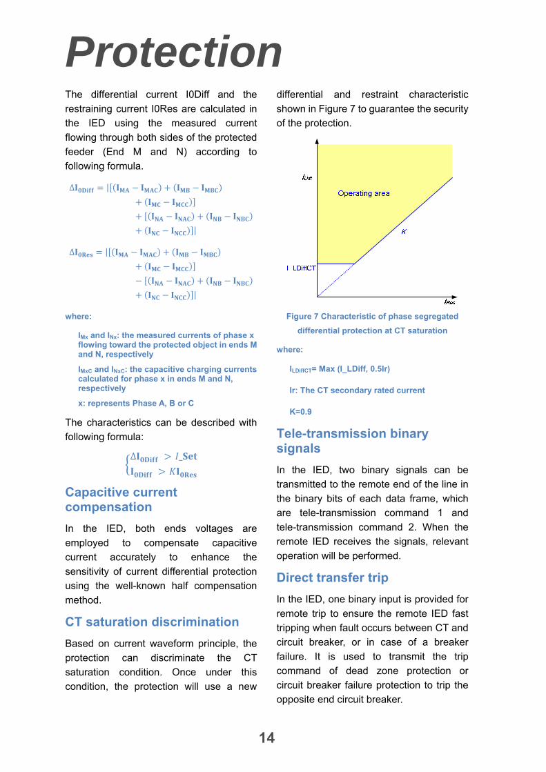
CT saturation discrimination
Based on current waveform principle, the
protection can discriminate the CT
saturation condition. Once under this
condition, the protection will use a new
differential and restraint characteristic
shown in Figure 7 to guarantee the security
of the protection.
Figure 7 Characteristic of phase segregated
differential protection at CT saturation
where:
ILDiffCT= Max (I_LDiff, 0.5Ir)
Ir: The CT secondary rated current
K=0.9
Tele-transmission binary signals
In the IED, two binary signals can be
transmitted to the remote end of the line in
the binary bits of each data frame, which
are tele-transmission command 1 and
tele-transmission command 2. When the
remote IED receives the signals, relevant
operation will be performed.
Direct transfer trip
In the IED, one binary input is provided for
remote trip to ensure the remote IED fast
tripping when fault occurs between CT and
circuit breaker, or in case of a breaker
failure. It is used to transmit the trip
command of dead zone protection or
circuit breaker failure protection to trip the
opposite end circuit breaker.
Protection
15
Time synchronization of Sampling
The differential protection of both end IEDs
can be set as master or slave mode. If one
IED is set as master, the IED at the other
end should be set as slave. To ensure
sampling synchronization between both
IEDs, the salve IED sends a frame of
synchronization request to master IED.
After the master IED receives the frame, it
returns a frame of data including its local
time. Then the slave IED can calculate
both the communication delay time and the
sampling time difference with the master
IED. Thus, the slave IED adjusts its
sampling time and the IEDs of both ends
come to complete sampling
synchronization.
Redundant remote communication channels
The differential protection is able to receive
data from the redundant remote
communication channels in parallel. When
one of the channels is broken, there is no
time delay for primary channel switching.
Switch onto fault protection function
Under either auto reclosing or manual
closing process, the protection function is
able to discriminate these conditions to
give an instantaneous tripping once closing
on permanent faulty line.
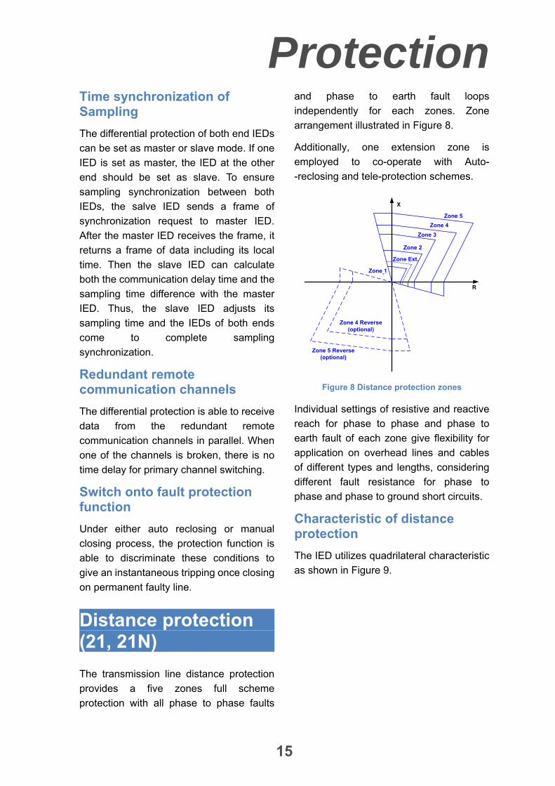
Distance protection (21, 21N)
The transmission line distance protection
provides a five zones full scheme
protection with all phase to phase faults
and phase to earth fault loops
independently for each zones. Zone
arrangement illustrated in Figure 8.
Additionally, one extension zone is
employed to co-operate with Auto-
-reclosing and tele-protection schemes.
R
Zone 1
X
Zone 2
Zone 3
Zone 4
Zone 5
Zone 4 Reverse (optional)
Zone 5 Reverse (optional)
Zone Ext.
Figure 8 Distance protection zones
Individual settings of resistive and reactive
reach for phase to phase and phase to
earth fault of each zone give flexibility for
application on overhead lines and cables
of different types and lengths, considering
different fault resistance for phase to
phase and phase to ground short circuits.
Characteristic of distance protection
The IED utilizes quadrilateral characteristic
as shown in Figure 9.
Protection
16
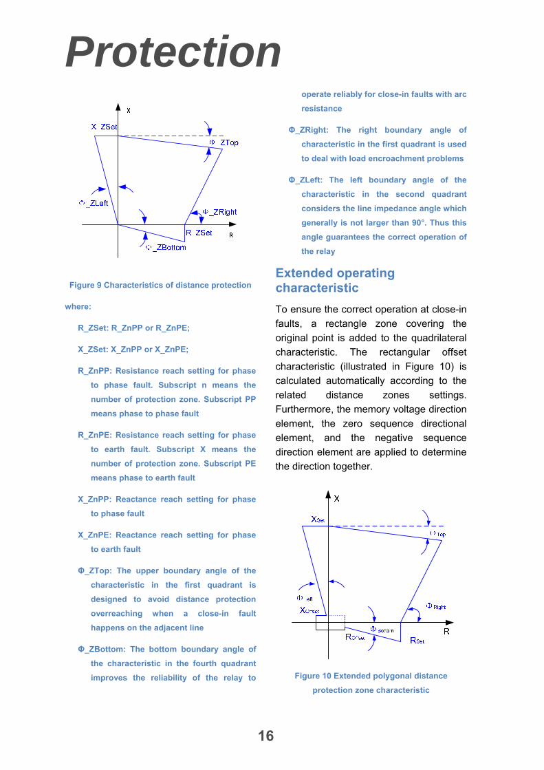
Figure 9 Characteristics of distance protection
where:
R_ZSet: R_ZnPP or R_ZnPE;
X_ZSet: X_ZnPP or X_ZnPE;
R_ZnPP: Resistance reach setting for phase
to phase fault. Subscript n means the
number of protection zone. Subscript PP
means phase to phase fault
R_ZnPE: Resistance reach setting for phase
to earth fault. Subscript X means the
number of protection zone. Subscript PE
means phase to earth fault
X_ZnPP: Reactance reach setting for phase
to phase fault
X_ZnPE: Reactance reach setting for phase
to earth fault
Φ_ZTop: The upper boundary angle of the
characteristic in the first quadrant is
designed to avoid distance protection
overreaching when a close-in fault
happens on the adjacent line
Φ_ZBottom: The bottom boundary angle of
the characteristic in the fourth quadrant
improves the reliability of the relay to
operate reliably for close-in faults with arc
resistance
Φ_ZRight: The right boundary angle of
characteristic in the first quadrant is used
to deal with load encroachment problems
Φ_ZLeft: The left boundary angle of the
characteristic in the second quadrant
considers the line impedance angle which
generally is not larger than 90°. Thus this
angle guarantees the correct operation of
the relay
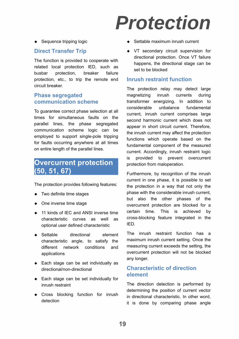
Extended operating characteristic
To ensure the correct operation at close-in
faults, a rectangle zone covering the
original point is added to the quadrilateral
characteristic. The rectangular offset
characteristic (illustrated in Figure 10) is
calculated automatically according to the
related distance zones settings.
Furthermore, the memory voltage direction
element, the zero sequence directional
element, and the negative sequence
direction element are applied to determine
the direction together.
Figure 10 Extended polygonal distance
protection zone characteristic

Protection
17
Reverse zone characteristic
In addition to the forward characteristic
zones mentioned above, the IED provides
two optional reverse zone characteristics
to protect connected busbar as a backup
protection. The reverse zone characteristic
can be set for zones 4 and 5 individually.
This reverse characteristic has been
shown in Figure 11.
Figure 11 Characteristic distance protection
reverse zone
Switch-onto- fault protection function
Under either auto reclosing or manual
closing process, the protection function is
able to discriminate these conditions to
give an instantaneous tripping once the
circuit breaker is closed on permanent
faulty line.
Power swing (68)
The IED provides a high reliable power
swing detector which discriminates
between fault and power swing with
different algorithm.
Power swing blocking logic
According to the slow behavior of power
swing phenomenon, once one of the two
following conditions is met, the protection
program will switch to power swing logic
process:
Without operation of sudden-change
current startup element, all
phase-to-phase impedances, ZAB, ZBC
and ZCA enter into the largest zone of
distance protection
Without operation of sudden-change
current startup element, all phase
currents are bigger than the power
swing current setting
In addition, according to the experimental
results of power swing, it is not possible for
impedance vector to come into protected
zones in 150 ms after triggering of the
current sudden- -change startup element.
After 150 ms, the protection program will
be switched to power swing logic process if
no tripping is issued.
Therefore, according to the above
condition, the IED program enters the
power swing logic process and the
distance protection is blocked until
removing of the mentioned conditions or
until a fault occurrence in the protected
line.
Power swing unblocking logic
The unblocking logic provides possibility
for selective tripping of faults on
transmission lines during system
oscillations, when the distance protection
function is normally blocked. In order to
unblock distance protection and therefore,
fast clearing of the faults, the following
elements are in service to discriminate
between an internal fault and power swing
conditions.

Protection
18
Asymmetric faults detection element
The zero and negative sequence
current are always the key features of
the asymmetric fault. By comparison
amongst the positive, negative and
zero sequence component of phase
current, the element distinguishes the
asymmetric fault from power swing.
Three phase fault detection element
Based on the experimental results and
practical proof, the change rate of
measuring resistance and the change
vector of measuring impedance are
combined to detect the three phase
fault during the power swing.
Tele-protection scheme for distance protection (85-21)
To achieve non-delayed and selective
tripping on 100 % of the line length for all
faults, the communication scheme logic is
provided for distance protection. The
communication schemes are as follows:
Permissive Overreach Transfer Trip
(POTT)
Permissive Underreach Transfer Trip
(PUTT)
Blocking scheme
Following protection logic are used to
ensure correct operation under some
special fault conditions:
Current reversal logic
Weak-infeed end and echo logic
Evolving fault logic
Sequence tripping logic
Direct Transfer Trip
The function is provided to cooperate with
related local protection IED, such as
busbar protection, breaker failure
protection, etc., to trip the opposite end
circuit breaker.
Phase segregated communication scheme
To guarantee correct phase selection at all
times for simultaneous faults on the
parallel lines, the phase segregated
communication scheme logic can be
employed to support single-pole tripping
for faults occurring anywhere at all times
on entire length of the parallel lines.
Tele-protection scheme for earth fault protection (85-67N)
To achieve highly sensitive and selective
tripping on 100 % of the line length for all
faults, especially at the high resistance
earth faults. It always works as
complement to tele-protection for distance
protection with a short time delay.
Permissive transfer trip communication
scheme is applied.
The protection provides dedicated current
and time elements independent of the
earth fault protection.
Following protection logic are used to
ensure correct operation under some
special fault conditions.
Current reversal logic
Weak-infeed end logic
Protection
19
Sequence tripping logic
Direct Transfer Trip
The function is provided to cooperate with
related local protection IED, such as
busbar protection, breaker failure
protection, etc., to trip the remote end
circuit breaker.
Phase segregated communication scheme
To guarantee correct phase selection at all
times for simultaneous faults on the
parallel lines, the phase segregated
communication scheme logic can be
employed to support single-pole tripping
for faults occurring anywhere at all times
on entire length of the parallel lines.
Overcurrent protection (50, 51, 67)
The protection provides following features:
Two definite time stages
One inverse time stage
11 kinds of IEC and ANSI inverse time
characteristic curves as well as
optional user defined characteristic
Settable directional element
characteristic angle, to satisfy the
different network conditions and
applications
Each stage can be set individually as
directional/non-directional
Each stage can be set individually for
inrush restraint
Cross blocking function for inrush
detection
Settable maximum inrush current
VT secondary circuit supervision for
directional protection. Once VT failure
happens, the directional stage can be
set to be blocked
Inrush restraint function
The protection relay may detect large
magnetizing inrush currents during
transformer energizing. In addition to
considerable unbalance fundamental
current, inrush current comprises large
second harmonic current which does not
appear in short circuit current. Therefore,
the inrush current may affect the protection
functions which operate based on the
fundamental component of the measured
current. Accordingly, inrush restraint logic
is provided to prevent overcurrent
protection from maloperation.
Furthermore, by recognition of the inrush
current in one phase, it is possible to set
the protection in a way that not only the
phase with the considerable inrush current,
but also the other phases of the
overcurrent protection are blocked for a
certain time. This is achieved by
cross-blocking feature integrated in the
IED.
The inrush restraint function has a
maximum inrush current setting. Once the
measuring current exceeds the setting, the
overcurrent protection will not be blocked
any longer.
Characteristic of direction element
The direction detection is performed by
determining the position of current vector
in directional characteristic. In other word,
it is done by comparing phase angle
Protection
20
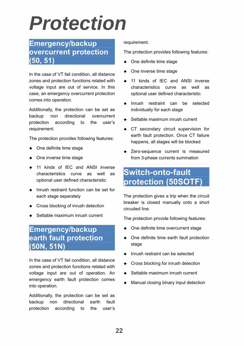
between the fault current and the reference
voltage, Figure 12 illustrates the direction
detection characteristic for phase A
element.
Forward
ΦPh_Char
Bisector
Figure 12 Direction detection characteristic of
overcurrent protection directional element
where:
ФPh_Char: The settable characteristic angle
The assignment of the applied measuring
values used in direction determination has
been shown in Table 1 for different types of
faults.
Table 1 Assignment of applied current and
reference voltage for directional element
Phase Current Voltage
A aI bcU
B bI caU
C cI abU
For three-phase short-circuit fault, without
any healthy phase, memory voltage values
are used to determine direction clearly if
the measured voltage values are not
sufficient. The detected direction is based
on the memory voltage of previous power
cycles.
Earth fault protection (50N, 51N, 67N)
The earth fault protection can be used to
clear phase to earth faults as system
back-up protection.
The protection provides following features:
Two definite time stages
One inverse time stage
11 kinds of the IEC and ANSI inverse
time characteristic curves as well as
optional user defined characteristic
Zero sequence directional element
Negative sequence directional element
is applied as a complement to zero
sequence directional element. It can be
enabled/disabled by setting
Each stage can be set individually as
directional/non-directional
Settable directional element
characteristic angle, to satisfy the
different network conditions and
applications
Each stage can be set individually for
inrush restraint
Settable maximum inrush current
VT secondary circuit supervision for
directional protection function. Once
VT failure happens, the directional
stage can be set to be blocked
CT secondary circuit supervision for
earth fault protection. Once CT failure
happens, all stages will be blocked

Protection
21
Zero-sequence current is measured
from earth phase CT
Directional element
The earth fault protection adopts zero
sequence directional element which
compares the zero sequence system
quantities:
3I0, current is measured from earth
phase CT
3U0, the voltage is used as reference
voltage. It is calculated from the sum of
the three phase voltages
Figure 13 Direction detection characteristic of
zero sequence directional element
where:
Ф0_Char: The settable characteristic angle
For earth fault protection, users can
choose negative sequence directional
element as the complement of zero
sequence directional element. It can be
used in case of too low zero sequence
voltage due to some fault condition e.g. the
unfavorable zero-sequence voltage. The
negative sequence directional element
characteristic is shown in Figure 14.
Figure 14 Direction detection characteristic of
negative sequence directional element
where:
Ф2_Char: The settable characteristic angle
Furthermore, under the VT failure situation,
it can be set to block directional earth fault
protection.
Inrush restraint function
The protection relay may detect large
magnetizing inrush currents during
transformer energizing. In addition to
considerable unbalance fundamental
current, Inrush current comprises large
second harmonic current which doesn’t
appear in short circuit current. Therefore,
the inrush current may affect the protection
functions which operate based on the
fundamental component of the measured
current. Accordingly, inrush restraint logic
is provided to prevent earth fault protection
from mis-tripping.
Since inrush current cannot be more than a
specified value, the inrush restraint
provides an upper current limit in which
blocking does not occur.
Protection
22
Emergency/backup overcurrent protection (50, 51)
In the case of VT fail condition, all distance
zones and protection functions related with
voltage input are out of service. In this
case, an emergency overcurrent protection
comes into operation.
Additionally, the protection can be set as
backup non directional overcurrent
protection according to the user’s
requirement.
The protection provides following features:
One definite time stage
One inverse time stage
11 kinds of IEC and ANSI inverse
characteristics curve as well as
optional user defined characteristic
Inrush restraint function can be set for
each stage separately
Cross blocking of inrush detection
Settable maximum inrush current
Emergency/backup earth fault protection (50N, 51N)
In the case of VT fail condition, all distance
zones and protection functions related with
voltage input are out of operation. An
emergency earth fault protection comes
into operation.
Additionally, the protection can be set as
backup non directional earth fault
protection according to the user’s
requirement.
The protection provides following features:
One definite time stage
One inverse time stage
11 kinds of IEC and ANSI inverse
characteristics curve as well as
optional user defined characteristic
Inrush restraint can be selected
individually for each stage
Settable maximum inrush current
CT secondary circuit supervision for
earth fault protection. Once CT failure
happens, all stages will be blocked
Zero-sequence current is measured
from 3-phase currents summation
Switch-onto-fault protection (50SOTF)
The protection gives a trip when the circuit
breaker is closed manually onto a short
circuited line.
The protection provide following features:
One definite time overcurrent stage
One definite time earth fault protection
stage
Inrush restraint can be selected
Cross blocking for inrush detection
Settable maximum inrush current
Manual closing binary input detection
Protection
23
Overload protection (50OL)
The IED supervises load flow in real time.
If each phase current is greater than the
dedicated setting for a set delay time, the
protection will issue alarm.
Overvoltage protection (59)
The overvoltage protection detects
abnormally network high voltage
conditions. Overvoltage conditions may
occur possibly in the power system during
abnormal conditions such as no-load,
lightly load, or open line end on long line.
The protection can be used as open line
end detector or as system voltage
supervision normally.
The protection provides following features:
Two definite time stages
Each stage can be set to alarm or trip
Measuring voltage between phase-
-earth voltage and phase-phase
(selectable)
Settable dropout ratio
Undervoltage protection (27)
One voltage reduction can occur in the
power system during faults or abnormal
conditions.
The protection provides following features:
Two definite time stages
Each stage can be set to alarm or trip
Measuring voltage between phase-
-earth voltage and phase-phase
selectable
Current criteria supervision
Circuit breaker aux. contact
supervision
VT secondary circuit supervision, the
Undervoltage function will be blocked
when VT failure happens
Settable dropout ratio
Breaker failure protection (50BF)
The circuit breaker failure protection is
designed to detect failure of the circuit
breaker during a fault clearance. It ensures
fast back-up tripping of surrounding
breakers by tripping relevant bus sections.
The protection can be single- or three-
-phase started to allow use with single or
three-phase tripping applications.
Once a circuit breaker operating failure
occurs on a feeder/transformer, the bus
section which the feeder/transformer is
connected with can be selectively isolated
by the protection. In addition a transfer trip
signal is issued to trip the opposite end
circuit breaker of the feeder.
In the event of a circuit breaker failure with
a busbar fault, a transfer trip signal is
issued to trip the remote end circuit
breaker of the feeder.
The current criteria are in combination with
three phase current, zero and negative
sequence current to achieve a higher
security.
Protection
24
The function can be set to give single- or
three phase re-tripping of the local breaker
to avoid unnecessary tripping of
surrounding breakers in the case of the
circuit breaker with two available trip coils.
Additionally, during single pole tripping,
stage 1 is able to re-tripping three phase
with settable delay time after single phase
re-tripping failure.
Two trip stages (local and surrounding
breaker tripping)
Transfer trip command to the remote
line end in second stage
Internal/ external initiation
Single/three phase CBF initiation
Selectable CB Aux contacts checking
Current criteria checking (including
phase current, zero and negative
sequence current)
Dead zone protection (50DZ)
The IED provides this protection function to
protect dead zone, namely the area
between circuit breaker and CT in the case
that CB is open. Therefore, by occurrence
of a fault in dead zone, the short circuit
current is measured by protection relay
while CB auxiliary contacts indicate the CB
is open.
Internal/external initiation
Self-adaptive for bus side CT or line
side CT
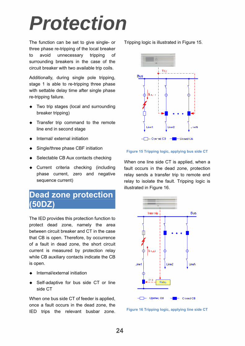
When one bus side CT of feeder is applied,
once a fault occurs in the dead zone, the
IED trips the relevant busbar zone.
Tripping logic is illustrated in Figure 15.
Figure 15 Tripping logic, applying bus side CT
When one line side CT is applied, when a
fault occurs in the dead zone, protection
relay sends a transfer trip to remote end
relay to isolate the fault. Tripping logic is
illustrated in Figure 16.
Figure 16 Tripping logic, applying line side CT

Protection
25
STUB protection (50STUB)
The VT is mostly installed at line side of
transmission lines. Therefore, for the cases
that transmission line is taken out of
service and the line disconnector is
opened, the distance protection will not be
able to operate and must be blocked.
The STUB protection protects the zone
between the CTs and the open dis-
-connector. The STUB protection is
enabled when the open position of the
disconnector is connected to IED binary
input. The function supports one definite
stage which related concept is shown in
Figure 17.
Figure 17 Tripping logic of STUB protection
Poles discordance protection (50PD)
The phase segregated operating circuit
breakers can be in different positions
(close-open) due to electrical or
mechanical failures during the system
normal operation.
The protection operates based on
information from auxiliary contacts of the
circuit breaker with additional criteria.
The protection performs following features:
3 phase CB Aux contacts supervision
Current criteria checking (including
phase current, zero and negative
sequence current)
Synchro-check and energizing check (25)
The synchro-check function checks the both side voltages of the circuit breaker for synchronism conditions.
The synchronization function ensures the
stability of the network in three phase
reclosing condition. To do this, the two side
voltages of the circuit breaker are
compared in terms of magnitude, phase
angle and frequency differences.
Additionally, closing can be done safely in
conditions that at least one side of the CB
has dead voltage.
Available for automatic reclosing
(internally or externally)
Based on voltage/ angle/ frequency
difference
Synchro-check modes:
Synch-check
Energizing check, and synch-check if
energizing check failure
Override

Protection
26
Modes of energizing check:
Dead V4 and dead V3Ph
Dead V4 and live V3Ph
Live V4 and dead V3Ph
Synchro-check reference voltage supervision
If the automatic reclosing is set for
synchronization check or energizing check,
during the automatic reclosing period, the
synchronization condition of the voltages
between both sides of CB cannot be met,
an alarm will be issued after default time
delay.
Auto-reclosing (79)
For restoration of the normal service after a
fault an auto reclosing attempt is mostly
made for overhead lines. Experiences
show that about 85% of faults have
transient nature and will disappear after an
auto reclosing attempt is performed. This
means that the line can be re-energized in
a short period. The reconnection is
accomplished after a dead time via the
automatic reclosing function. If the fault is
permanent or short circuit arc has not been
extinguished, the protection will re-trip the
breaker. Main features of the
Auto-reclosing are as follows:
Up to 4 shots (selectable)
Individually settable dead time for three
phase and single phase fault and for
each shot
Internal/external AR initiation
Single/three phase AR operation
CB status supervision
CB Aux. contact supervision
Cooperation with internal synch-check
function for reclosing command
Secondary system supervision
Current transformer secondary circuit supervision
Open or short circuited CT cores can
cause unwanted operation of some
protection functions such as differential,
earth fault current and negative sequence
current functions.
Interruption of the CT secondary circuit is
detected based on zero-sequence current.
Once CT failure happens, each stage of
earth fault protection is blocked.
Furthermore, when the zero-sequence
current is always lager than the setting
value of “3I0_CT Fail” for 12s while one
phase current is less than a low current
threshold, or the calculated differential
current of both sides is always lager than a
threshold for 12s while one phase current
is less than the low current threshold, an
alarm will be reported. Blocking current
differential protection or not can be set in
this condition. If blocking is selected, it can
be decided further to blocking three
phases or only blocking the faulty phase.
Voltage transformer secondary circuit supervision
A measured voltage failure, due to a
broken conductor or a short circuit fault in
the secondary circuit of voltage transformer,
may result in unwanted operation of the
protection functions which work based on
voltage criteria. VT failure supervision

Protection
27
function is provided to block these
protection functions and enable the backup
protection functions. The features of the
function are as follows:
Symmetrical/asymmetrical VT failure
detection
3-phase AC voltage MCB monitoring
1-phase AC voltage MCB monitoring
Zero and negative sequence current
monitoring
Applicable in solid grounded,
compensated or isolated networks
Monitoring
28
Phase-sequence of voltage and current supervision
The phase-sequence of three phase
voltage and current are monitored in the
normal condition to determine that the
secondary circuit of CT or VT is connected
with IED correctly.
3I0 polarity supervision
The IED compare the magnitude and
phase angle of the calculated zero
sequence current with the measured one
to determine that the polarity is connected
in a right way.
The third harmonic of voltage supervision
If the third harmonic voltage is excessive,
the alarm without blocking protection will
be given with delay time for checking of the
secondary circuit of voltage transformer.
Auxiliary contacts of circuit breaker supervision
Current flowing through the transmission
line and connected CB aux. contacts are
monitored in phase segregated. Therefore,
the conflict condition is reported as alarm.
For example, If CB aux. contacts indicate
that CB is open in phase A and at the same
time flowing current is measured in this
phase, related alarm is reported.
Broken conductor detection
The main purpose of the broken conductor
detection function is to detect the broken
conductors on protected transmission lines
and cables. Detection can initiate an alarm
or tripping.
Self-supervision
All modules can perform self-
supervision to its key hardware
components and program, as soon as
energizing. Parts of the modules are
self-supervised in real time. All internal
faults or abnormal conditions will
initiate an alarm. The fatal faults among
them will result in the whole IED
blocked
The sampled data from the redundant
A/D sampling channels compare with
each other in real time. If the difference
exceeds the specified threshold, it will
be considered as analog input channel
fault and the protection will be blocked
immediately
CPU module and communication
module perform real time inter-
-supervision. Therefore communication
interruption between them is detected
and related alarm will be given
CRC checks for the setting, program
and configuration, etc.
Fault locator
The built-in fault locator is an impedance
measuring function giving the distance
from the IED measuring location to the
fault position in km. The IED reports fault
location after the IED tripping.

Communication
29
Station communication
Overview
The IED is able to connect to one or
more substation level systems or
equipments simultaneously, through the
communication ports with communica-
-tion protocols supported. (Shown in
Figure 18)
Front communication port
There is a serial RS232 port on the front
plate of all the IEDs. Through this port,
the IED can be connected to the
personal computer for setting, testing,
and configuration using the dedicated
Sifang software tool.
RS485 communication ports
Up to 2 isolated electrical RS485
communication ports are provided to
connect with substation automation
system. These two ports can work in
parallel for IEC60870-5-103.
Ethernet communication ports
Up to 3 electrical or optical Ethernet
communication ports are provided to
connect with substation automation system.
These two out of three ports can work in
parallel for protocol, IEC61850 or
IEC60870-5-103.
Figure 18 Connection example for multi-networks of station automation system
Note: All four ports can work in parallel
Communication protocol
The IED supports station communication
with IEC 61850-8 and IED60870-5-103
protocols.
By means of IEC61850, GOOSE peer-
-to-peer communication make it possible
that bay IEDs can exchange information to
each other directly, and a simple
master-less system can be set up for bay
and system interlocking and other
interactive function.
Time synchronization port
Communication
30
All IEDs feature a permanently integrated
electrical time synchronization port. It can
be used to feed timing telegrams in IRIG-B
or pulse format into the IEDs via time
synchronization receivers. The IED can
adapt the second or minute pulse in the
pulse mode automatically.
Meanwhile, SNTP network time synchro-
-nization can be applied.
The
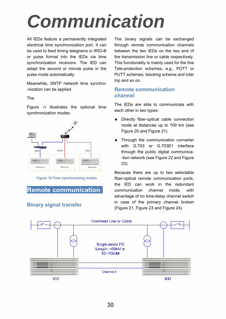
Figure 19 illustrates the optional time
synchronization modes.
SNTP IRIG-B Pulse
Ethernet port IRIG-B port Binary input
Figure 19 Time synchronizing modes
Remote communication
Binary signal transfer
The binary signals can be exchanged
through remote communication channels
between the two IEDs on the two end of
the transmission line or cable respectively.
This functionality is mainly used for the line
Tele-protection schemes, e.g., POTT or
PUTT schemes, blocking scheme and inter
trip and so on.
Remote communication channel
The IEDs are able to communicate with
each other in two types:
Directly fiber-optical cable connection
mode at distances up to 100 km (see
Figure 20 and Figure 21)
Through the communication converter
with G.703 or G.703E1 interface
through the public digital communica-
-tion network (see Figure 22 and Figure
23)
Because there are up to two selectable
fiber-optical remote communication ports,
the IED can work in the redundant
communication channel mode, with
advantage of no time-delay channel switch
in case of the primary channel broken
(Figure 21, Figure 23 and Figure 24).
Communication
31
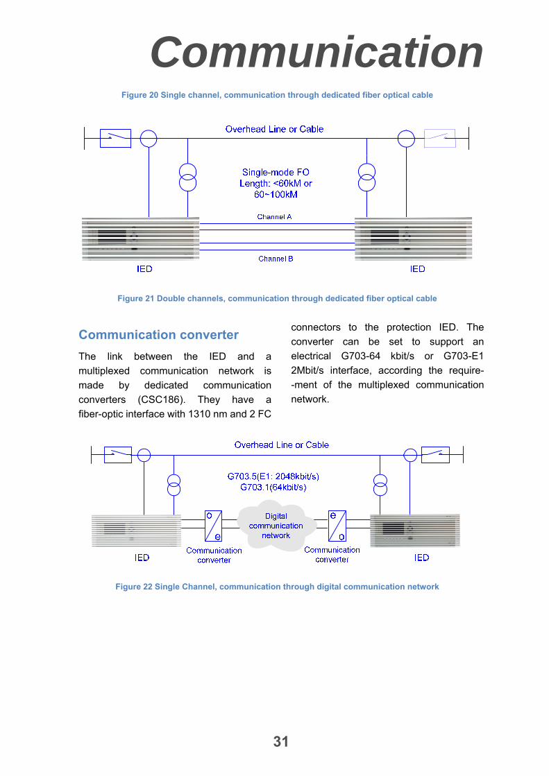
Figure 20 Single channel, communication through dedicated fiber optical cable
Figure 21 Double channels, communication through dedicated fiber optical cable
Communication converter
The link between the IED and a
multiplexed communication network is
made by dedicated communication
converters (CSC186). They have a
fiber-optic interface with 1310 nm and 2 FC
connectors to the protection IED. The
converter can be set to support an
electrical G703-64 kbit/s or G703-E1
2Mbit/s interface, according the require-
-ment of the multiplexed communication
network.
Figure 22 Single Channel, communication through digital communication network

Communication
32
Figure 23 Double channels, communication through digital communication network
Figure 24 Double channels, one channel through digital communication network, one channel
through dedicated fiber optical cables
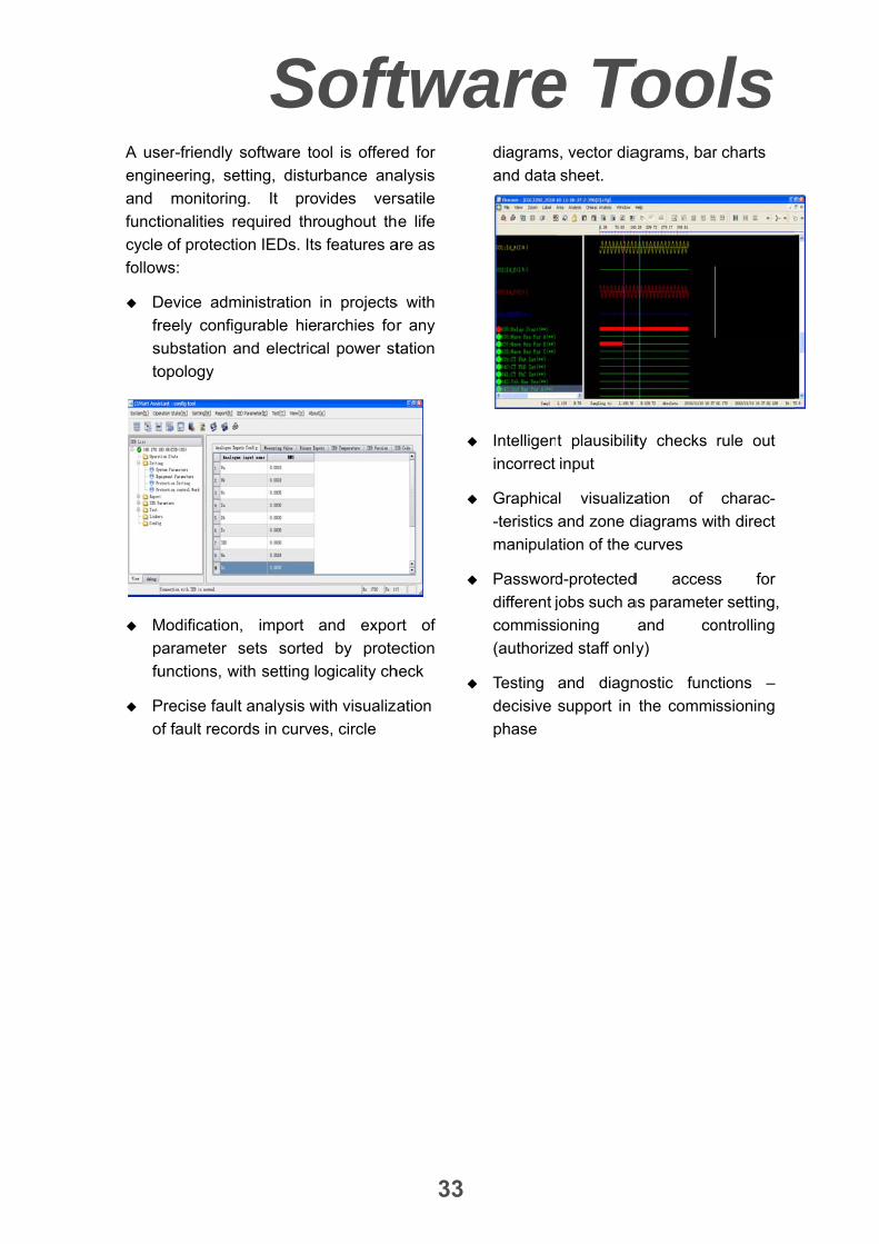
A us
engin
and
funct
cycle
follow
D
fr
s
to
M
p
fu
P
o
ser-friendly
neering, se
monitoring
tionalities re
e of protecti
ws:
Device adm
reely config
substation a
opology
Modification
parameter s
unctions, w
Precise fault
of fault reco
Ssoftware to
etting, distu
g. It pro
equired thr
on IEDs. Its
ministration
gurable hie
and electric
, import
sets sorted
with setting l
t analysis w
rds in curve
oftool is offere
rbance ana
vides vers
oughout th
s features a
in projects
rarchies for
al power st
and expor
d by prote
ogicality ch
with visualiza
es, circle
twa
33
ed for
alysis
rsatile
e life
are as
s with
r any
tation
rt of
ection
heck
ation
arediagrams
and data
Intelligen
incorrect
Graphica
-teristics
manipula
Password
different j
commiss
(authoriz
Testing
decisive
phase
e Tos, vector dia
sheet.
t plausibilit
input
al visualiza
and zone d
ation of the c
d-protected
jobs such a
ioning
ed staff only
and diagn
support in
Tooagrams, bar
ty checks
ation of
diagrams wi
curves
d access
as paramete
and co
y)
nostic func
the commi
ols r charts
rule out
charac-
ith direct
s for
er setting,
ontrolling
ctions –
ssioning

Hardware
34
Front plate
The whole front plate is divided into
zones, each of them with a well-defined
functionality:
Figure 25 Front plate
1 Liquid crystal display (LCD)
2 LEDs
3 Shortcut function keys
4 Arrow keys
5 Reset key
6 Quit key
7 Set key
8 RS232 communication port
Rear plate
Figure 26 Rear plate of the protection IED
Hardware
35
Modules
Analogue Input Module (AIM)
The analogue input module is used to
galvanically separate and transform the
secondary currents and voltages
generated by the measuring transformers.
CPU Module (CPU)
The CPU module handles all protection
functions and logic. There are two CPU
modules in the IED, CPU1 and CPU2 with
the same software and different hardware.
They work in parallel and interlock each
other to prevent maloperation due to the
internal faults of one CPU modules.
The CPU1 provides compatible data ports
with 64kbps and 2Mbps used for
differential protection, which can be
configured 1or 2 data ports according to
requirement. There are two versions for
CPU1 with single channel or double
channel. The double channel CPU1 is
compatible completely with single channel
CPU1.
Moreover, the redundant A/D sampling
channels are equipped. By comparing the
data from redundant sampling channels,
any sampling data errors and the channel
hardware faults can be detected
immediately and the proper alarm and
blocking is initiated in time.
Communication Module (COM)
The communication module performs
communication between the internal
protection system and external equipments
such as HMI, engineering workstation,
substation automation system, RTU, etc.,
to transmit remote metering, remote
signaling, SOE, event reports and record
data.
Up to 3 channels isolated electrical or
optical Ethernet ports and up to 2 channels
RS485 serial communication ports can be
provided in communication module to meet
the communication demands of different
substation automation system and RTU at
the same time.
The time synchronization port is equipped,
which can work in pulse mode or IRIG-B
mode. SNTP mode can be applied through
communication port.
In addition, a series printer port is also
reserved.
Binary Input Module (BIM)
The binary input module is used to connect
the input signals and alarm signals such as
the auxiliary contacts of the circuit breaker
(CB), etc.
Binary Output Module (BOM)
The binary output modules mainly provide
tripping output contacts, initiating output
contacts and signaling output contacts. All
the tripping output relays have contacts
with a high switching capacity and are
blocked by protection startup elements.
Each output relay can be configured to
satisfy the demands of users.
Power Supply Module (PSM)
The power supply module is used to
provide the correct internal voltages and
full isolation between the terminal and the
battery system.

Hardware
36
Dimension
Figure 27 4U, 19” case with rear cover
Table 2 Dimension of the IED case
Legend A B C D E
Dimension (mm) 177 482.6 265 320 437.2
Figure 28 Cut-out on the panel
Table 3 Dimension of the cutout for IED mounting
Legend A B C D E
Dimension (mm) 450 465 103.6 178 6.5
Connection
37
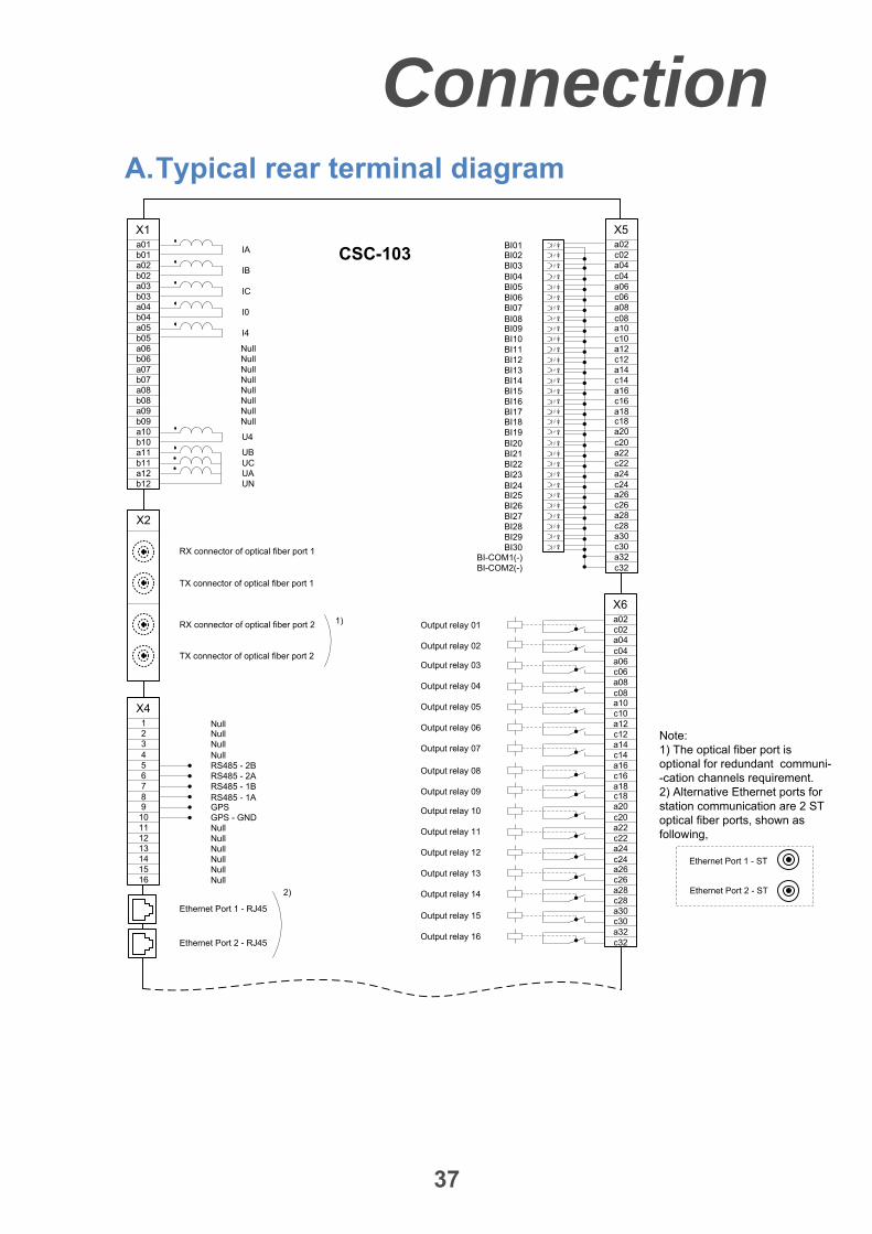
A. Typical rear terminal diagram
X1
CSC-103a01
IAb01a02
IBb02a03
ICb03a04
I0b04a05
I4b05
a10U4
b10
a09
UB
b09
UCUA
a11b11a12b12 UN
NullNull
X5a02
BI02 c02BI03 a04BI04 c04BI05 a06BI06 c06BI07 a08BI08 c08BI09 a10
BI01
BI10 c10BI11 a12BI12 c12BI13 a14BI14 c14BI15 a16BI16 c16BI17 a18BI18 c18BI19 a20BI20 c20BI21 a22BI22 c22BI23 a24BI24 c24BI25 a26BI26 c26BI27 a28BI28 c28BI29 a30BI30 c30
a32c32
BI-COM1(-)BI-COM2(-)
X4123456789
10111213141516
Ethernet Port 1 - RJ45
Ethernet Port 2 - RJ45
NullNullNullRS485 - 2BRS485 - 2ARS485 - 1BRS485 - 1AGPS
Null
GPS - GNDNullNullNullNullNullNull
X6a02c02a04c04a06c06a08c08a10c10a12c12a14c14a16c16a18c18a20c20a22c22a24c24a26c26a28c28a30c30a32c32
2)
Ethernet Port 1 - ST
Ethernet Port 2 - ST
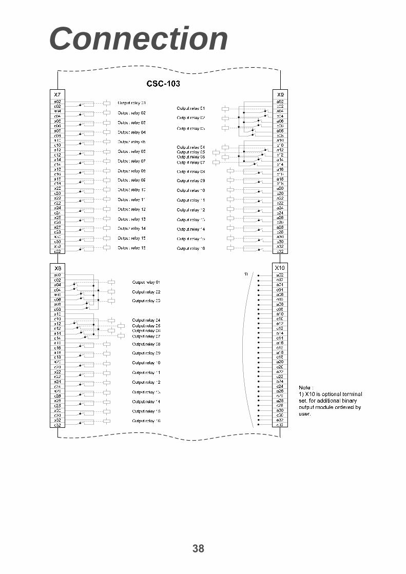
Note:1) The optical fiber port is optional for redundant communi--cation channels requirement.2) Alternative Ethernet ports for station communication are 2 ST optical fiber ports, shown as following,
a06b06a07b07a08b08
NullNull
NullNull
NullNull
RX connector of optical fiber port 1
X2
Output relay 01
Output relay 02
Output relay 03
Output relay 04
Output relay 05
Output relay 06
Output relay 07
Output relay 08
Output relay 09
Output relay 10
Output relay 11
Output relay 12
Output relay 13
Output relay 14
Output relay 15
Output relay 16
1)
TX connector of optical fiber port 1
RX connector of optical fiber port 2
TX connector of optical fiber port 2
Connection
38

Connection
39

Connection
40
B. Typical analogue inputs connection for one breaker of single or double busbar arrangement

Connection
41
C. Typical analogue inputs connection for one and half breaker arrangement
Technical data
42
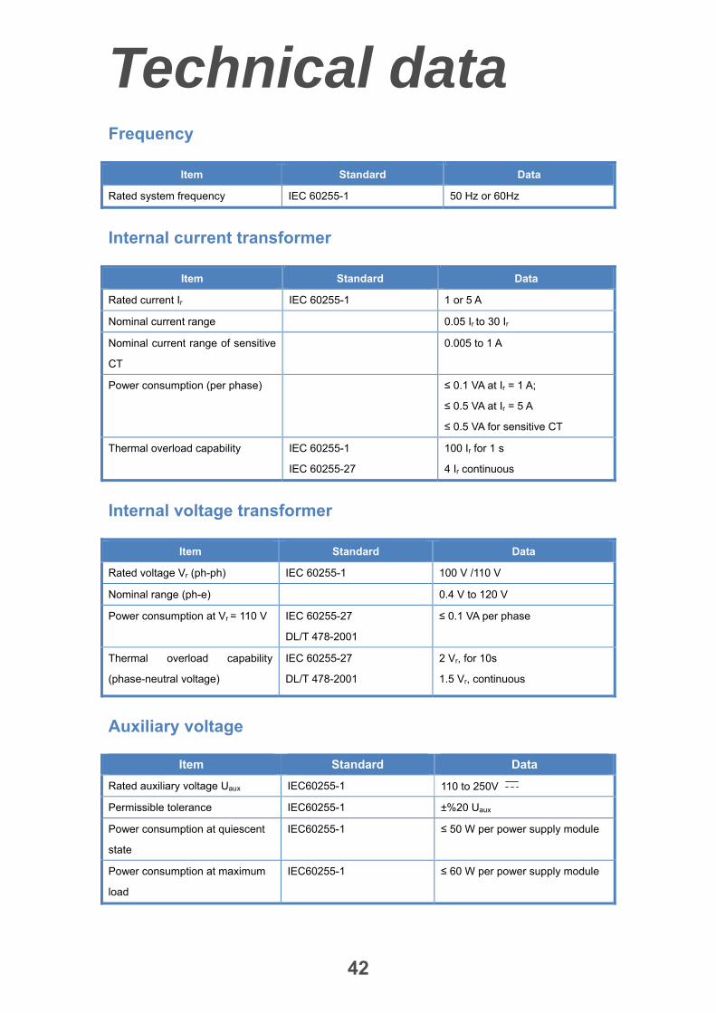
Frequency
Item Standard Data
Rated system frequency IEC 60255-1 50 Hz or 60Hz
Internal current transformer
Item Standard Data
Rated current Ir IEC 60255-1 1 or 5 A
Nominal current range 0.05 Ir to 30 Ir
Nominal current range of sensitive
CT
0.005 to 1 A
Power consumption (per phase) ≤ 0.1 VA at Ir = 1 A;
≤ 0.5 VA at Ir = 5 A
≤ 0.5 VA for sensitive CT
Thermal overload capability IEC 60255-1
IEC 60255-27
100 Ir for 1 s
4 Ir continuous
Internal voltage transformer
Item Standard Data
Rated voltage Vr (ph-ph) IEC 60255-1 100 V /110 V
Nominal range (ph-e) 0.4 V to 120 V
Power consumption at Vr = 110 V IEC 60255-27
DL/T 478-2001
≤ 0.1 VA per phase
Thermal overload capability
(phase-neutral voltage)
IEC 60255-27
DL/T 478-2001
2 Vr, for 10s
1.5 Vr, continuous
Auxiliary voltage
Item Standard Data
Rated auxiliary voltage Uaux IEC60255-1 110 to 250V
Permissible tolerance IEC60255-1 ±%20 Uaux
Power consumption at quiescent
state
IEC60255-1 ≤ 50 W per power supply module
Power consumption at maximum
load
IEC60255-1 ≤ 60 W per power supply module

Technical data
43
Inrush Current IEC60255-1 T ≤ 10 ms/I≤ 25 A per power supply
module,
Binary inputs
Item Standard Data
Input voltage range IEC60255-1 110/125 V
220/250 V
Threshold1: guarantee
operation
IEC60255-1 154V, for 220/250V
77V, for 110V/125V
Threshold2: uncertain operation IEC60255-1 132V, for 220/250V ;
66V, for 110V/125V
Response time/reset time IEC60255-1 Software provides de-bounce
time
Power consumption, energized IEC60255-1 Max. 0.5 W/input, 110V
Max. 1 W/input, 220V
Binary outputs
Item Standard Data
Max. system voltage IEC60255-1 250V /~
Current carrying capacity IEC60255-1 5 A continuous,
30A,200ms ON, 15s OFF
Making capacity IEC60255-1 1100 W( ) at inductive load with
L/R>40 ms
1000 VA(AC)
Breaking capacity IEC60255-1 220V , 0.15A, at L/R≤40 ms
110V , 0.30A, at L/R≤40 ms
Mechanical endurance, Unloaded IEC60255-1 50,000,000 cycles (3 Hz switching
frequency)
Mechanical endurance, making IEC60255-1 ≥1000 cycles
Mechanical endurance, breaking IEC60255-1 ≥1000 cycles
Specification state verification IEC60255-1
IEC60255-23
IEC61810-1
UL/CSA、TŰV
Technical data
44
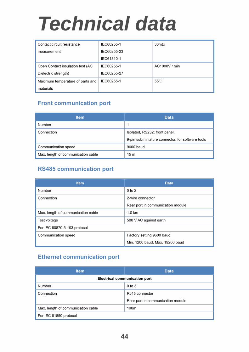
Contact circuit resistance
measurement
IEC60255-1
IEC60255-23
IEC61810-1
30mΩ
Open Contact insulation test (AC
Dielectric strength)
IEC60255-1
IEC60255-27
AC1000V 1min
Maximum temperature of parts and
materials
IEC60255-1 55
Front communication port
Item Data
Number 1
Connection Isolated, RS232; front panel,
9-pin subminiature connector, for software tools
Communication speed 9600 baud
Max. length of communication cable 15 m
RS485 communication port
Item Data
Number 0 to 2
Connection 2-wire connector
Rear port in communication module
Max. length of communication cable 1.0 km
Test voltage 500 V AC against earth
For IEC 60870-5-103 protocol
Communication speed Factory setting 9600 baud,
Min. 1200 baud, Max. 19200 baud
Ethernet communication port
Item Data
Electrical communication port
Number 0 to 3
Connection RJ45 connector
Rear port in communication module
Max. length of communication cable 100m
For IEC 61850 protocol

Technical data
45
Communication speed 100 Mbit/s
For IEC 60870-5-103 protocol
Communication speed 100 Mbit/s
Optical communication port ( optional )
Number 0 to 2
Connection SC connector
Rear port in communication module
Optical cable type Multi-mode
Max. length of communication cable 2.0km
IEC 61850 protocol
Communication speed 100 Mbit/s
IEC 60870-5-103 protocol
Communication speed 100 Mbit/s
Time synchronization
Item Data
Mode Pulse mode
IRIG-B signal format IRIG-B000
Connection 2-wire connector
Rear port in communication module
Voltage levels differential input
Fiber optic communication ports for remote communication
Item Data
Number 1 to 2
Fiber optic cable type Single-mode
Optic wavelength 1310nm, when the transmission distance <60km;
1550nm, when the transmission distance >60km
Optic received sensitivity -38dBm
Emitter electric level >-8dBm; (the transmission distance <40km)
>-4dBm; (the transmission distance 40~60km)
>-3dBm; (the transmission distance >60km)
Fiber optic connector type FC, when the transmission distance <60km)
SC, when the transmission distance >60km
Data transmission rate 64 kbit/s, G703;
2,048 kbit/s, G703-E1
Max. transmission distance 100kM

Technical data
46
Environmental influence
Item Data
Recommended permanent operating temperature -10 °C to +55°C
(Legibility of display may be impaired above
+55 °C /+131 °F)
Storage and transport temperature limit -25°C to +70°C
Permissible humidity 95 % of relative humidity
IED design
Item Data
Case size 4U×19inch
Weight ≤ 10kg

Technical Data
47
Product safety-related Tests
Item Standard Data
Over voltage category IEC60255-27 Category III
Pollution degree IEC60255-27 Degree 2
Insulation IEC60255-27 Basic insulation
Degree of protection (IP) IEC60255-27
IEC 60529
Front plate: IP40
Rear, side, top and bottom: IP 30
Power frequency high voltage
withstand test
IEC 60255-5
EN 60255-5
ANSI C37.90
GB/T 15145-2001
DL/T 478-2001
2KV, 50Hz
2.8kV
between the following circuits:
auxiliary power supply
CT / VT inputs
binary inputs
binary outputs
case earth
500V, 50Hz
between the following circuits:
Communication ports to case
earth
time synchronization terminals
to case earth
Impulse voltage test IEC60255-5
IEC 60255-27
EN 60255-5
ANSI C37.90
GB/T 15145-2001
DL/T 478-2001
5kV (1.2/50μs, 0.5J)
If Ui≥63V
1kV if Ui<63V
Tested between the following
circuits:
auxiliary power supply
CT / VT inputs
binary inputs
binary outputs
case earth
Note: Ui: Rated voltage
Insulation resistance IEC60255-5
IEC 60255-27
EN 60255-5
ANSI C37.90
GB/T 15145-2001
≥ 100 MΩ at 500 V

Technical Data
48
DL/T 478-2001
Protective bonding resistance IEC60255-27 ≤ 0.1Ω
Fire withstand/flammability IEC60255-27 Class V2
Electromagnetic immunity tests
Item Standard Data
1 MHz burst immunity test IEC60255-22-1
IEC60255-26
IEC61000-4-18
EN 60255-22-1
ANSI/IEEE C37.90.1
Class III
2.5 kV CM ; 1 kV DM
Tested on the following circuits:
auxiliary power supply
CT / VT inputs
binary inputs
binary outputs
1 kV CM ; 0 kV DM
Tested on the following circuits:
communication ports
Electrostatic discharge IEC 60255-22-2
IEC 61000-4-2
EN 60255-22-2
Level 4
8 kV contact discharge;
15 kV air gap discharge;
both polarities; 150 pF; Ri = 330 Ω
Radiated electromagnetic field
disturbance test
IEC 60255-22-3
EN 60255-22-3
Frequency sweep:
80 MHz – 1 GHz; 1.4 GHz – 2.7 GHz
spot frequencies:
80 MHz; 160 MHz; 380 MHz; 450
MHz; 900 MHz; 1850 MHz; 2150
MHz
10 V/m
AM, 80%, 1 kHz
Radiated electromagnetic field
disturbance test
IEC 60255-22-3
EN 60255-22-3
Pulse-modulated
10 V/m, 900 MHz; repetition rate
200 Hz, on duration 50 %
Electric fast transient/burst immunity
test
IEC 60255-22-4,
IEC 61000-4-4
EN 60255-22-4
ANSI/IEEE C37.90.1
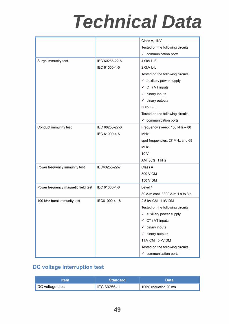
Class A, 4KV
Tested on the following circuits:
auxiliary power supply
CT / VT inputs
binary inputs
binary outputs
Technical Data
49
Class A, 1KV
Tested on the following circuits:
communication ports
Surge immunity test IEC 60255-22-5
IEC 61000-4-5
4.0kV L-E
2.0kV L-L
Tested on the following circuits:
auxiliary power supply
CT / VT inputs
binary inputs
binary outputs
500V L-E
Tested on the following circuits:
communication ports
Conduct immunity test IEC 60255-22-6
IEC 61000-4-6
Frequency sweep: 150 kHz – 80
MHz
spot frequencies: 27 MHz and 68
MHz
10 V
AM, 80%, 1 kHz
Power frequency immunity test IEC60255-22-7 Class A
300 V CM
150 V DM
Power frequency magnetic field test IEC 61000-4-8 Level 4
30 A/m cont. / 300 A/m 1 s to 3 s
100 kHz burst immunity test IEC61000-4-18 2.5 kV CM ; 1 kV DM
Tested on the following circuits:
auxiliary power supply
CT / VT inputs
binary inputs
binary outputs
1 kV CM ; 0 kV DM
Tested on the following circuits:
communication ports
DC voltage interruption test
Item Standard Data
DC voltage dips IEC 60255-11 100% reduction 20 ms

Technical Data
50
60% reduction 200 ms
30% reduction 500 ms
DC voltage interruptions IEC 60255-11 100% reduction 5 s
DC voltage ripple IEC 60255-11 15%, twice rated frequency
DC voltage gradual shut–down
/start-up
IEC 60255-11 60 s shut down ramp
5 min power off
60 s start-up ramp
DC voltage reverse polarity IEC 60255-11 1 min
Electromagnetic emission test
Item Standard Data
Radiated emission IEC60255-25
EN60255-25
CISPR22
30MHz to 1GHz ( IT device may up
to 5 GHz)
Conducted emission IEC60255-25
EN60255-25
CISPR22
0.15MHz to 30MHz
Mechanical tests
Item Standard Data
Sinusoidal Vibration response
test
IEC60255-21-1
EN 60255-21-1
Class 1
10 Hz to 60 Hz: 0.075 mm
60 Hz to 150 Hz: 1 g
1 sweep cycle in each axis
Relay energized
Sinusoidal Vibration endurance
test
IEC60255-21-1
EN 60255-21-1
Class 1
10 Hz to 150 Hz: 1 g
20 sweep cycle in each axis
Relay non-energized
Shock response test IEC60255-21-2
EN 60255-21-2
Class 1
5 g, 11 ms duration
3 shocks in both directions of 3 axes
Relay energized
Shock withstand test IEC60255-21-2
EN 60255-21-2
Class 1
15 g, 11 ms duration
3 shocks in both directions of 3 axes
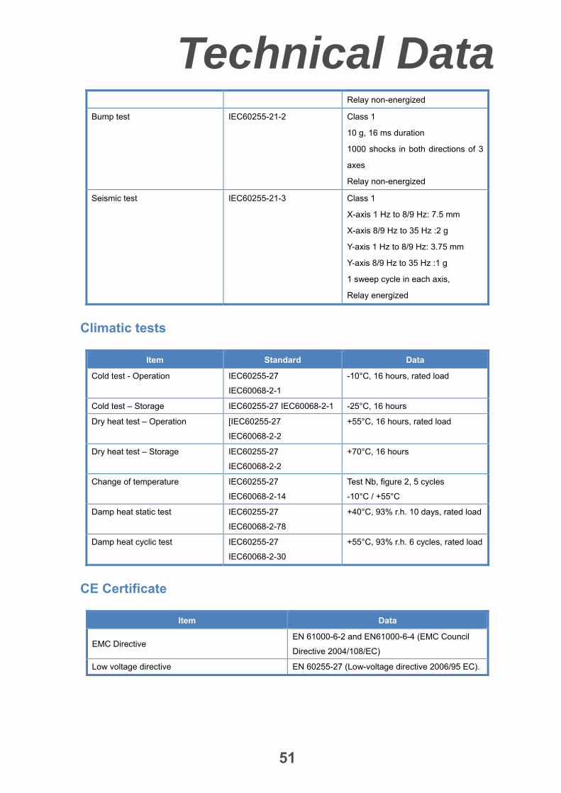
Technical Data
51
Relay non-energized
Bump test IEC60255-21-2 Class 1
10 g, 16 ms duration
1000 shocks in both directions of 3
axes
Relay non-energized
Seismic test IEC60255-21-3 Class 1
X-axis 1 Hz to 8/9 Hz: 7.5 mm
X-axis 8/9 Hz to 35 Hz :2 g
Y-axis 1 Hz to 8/9 Hz: 3.75 mm
Y-axis 8/9 Hz to 35 Hz :1 g
1 sweep cycle in each axis,
Relay energized
Climatic tests
Item Standard Data
Cold test - Operation IEC60255-27
IEC60068-2-1
-10°C, 16 hours, rated load
Cold test – Storage IEC60255-27 IEC60068-2-1 -25°C, 16 hours
Dry heat test – Operation [IEC60255-27
IEC60068-2-2
+55°C, 16 hours, rated load
Dry heat test – Storage IEC60255-27
IEC60068-2-2
+70°C, 16 hours
Change of temperature IEC60255-27
IEC60068-2-14
Test Nb, figure 2, 5 cycles
-10°C / +55°C
Damp heat static test IEC60255-27
IEC60068-2-78
+40°C, 93% r.h. 10 days, rated load
Damp heat cyclic test IEC60255-27
IEC60068-2-30
+55°C, 93% r.h. 6 cycles, rated load
CE Certificate
Item Data
EMC Directive EN 61000-6-2 and EN61000-6-4 (EMC Council
Directive 2004/108/EC)
Low voltage directive EN 60255-27 (Low-voltage directive 2006/95 EC).
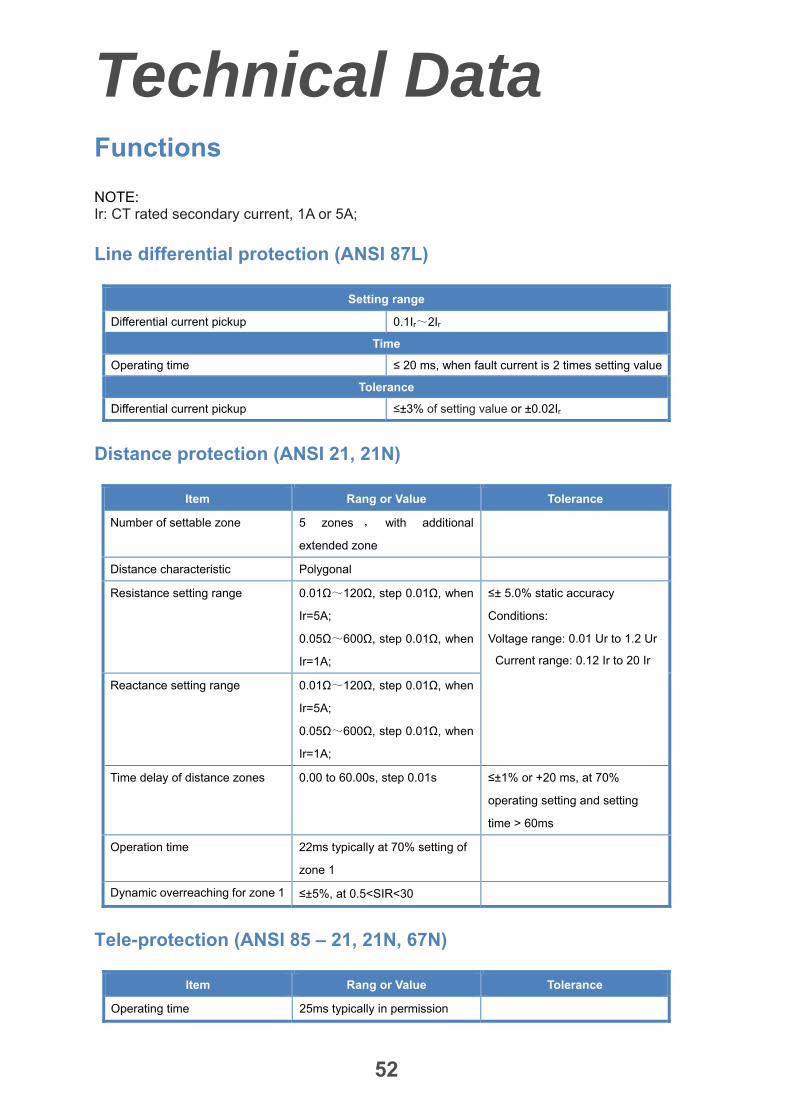
Technical Data
52
Functions
NOTE: Ir: CT rated secondary current, 1A or 5A;
Line differential protection (ANSI 87L)
Setting range
Differential current pickup 0.1Ir~2Ir
Time
Operating time ≤ 20 ms, when fault current is 2 times setting value
Tolerance
Differential current pickup ≤±3% of setting value or ±0.02Ir
Distance protection (ANSI 21, 21N)
Item Rang or Value Tolerance
Number of settable zone 5 zones , with additional
extended zone
Distance characteristic Polygonal
Resistance setting range 0.01Ω~120Ω, step 0.01Ω, when
Ir=5A;
0.05Ω~600Ω, step 0.01Ω, when
Ir=1A;
≤± 5.0% static accuracy
Conditions:
Voltage range: 0.01 Ur to 1.2 Ur
Current range: 0.12 Ir to 20 Ir
Reactance setting range 0.01Ω~120Ω, step 0.01Ω, when
Ir=5A;
0.05Ω~600Ω, step 0.01Ω, when
Ir=1A;
Time delay of distance zones 0.00 to 60.00s, step 0.01s ≤±1% or +20 ms, at 70%
operating setting and setting
time > 60ms
Operation time 22ms typically at 70% setting of
zone 1
Dynamic overreaching for zone 1 ≤±5%, at 0.5<SIR<30
Tele-protection (ANSI 85 – 21, 21N, 67N)
Item Rang or Value Tolerance
Operating time 25ms typically in permission
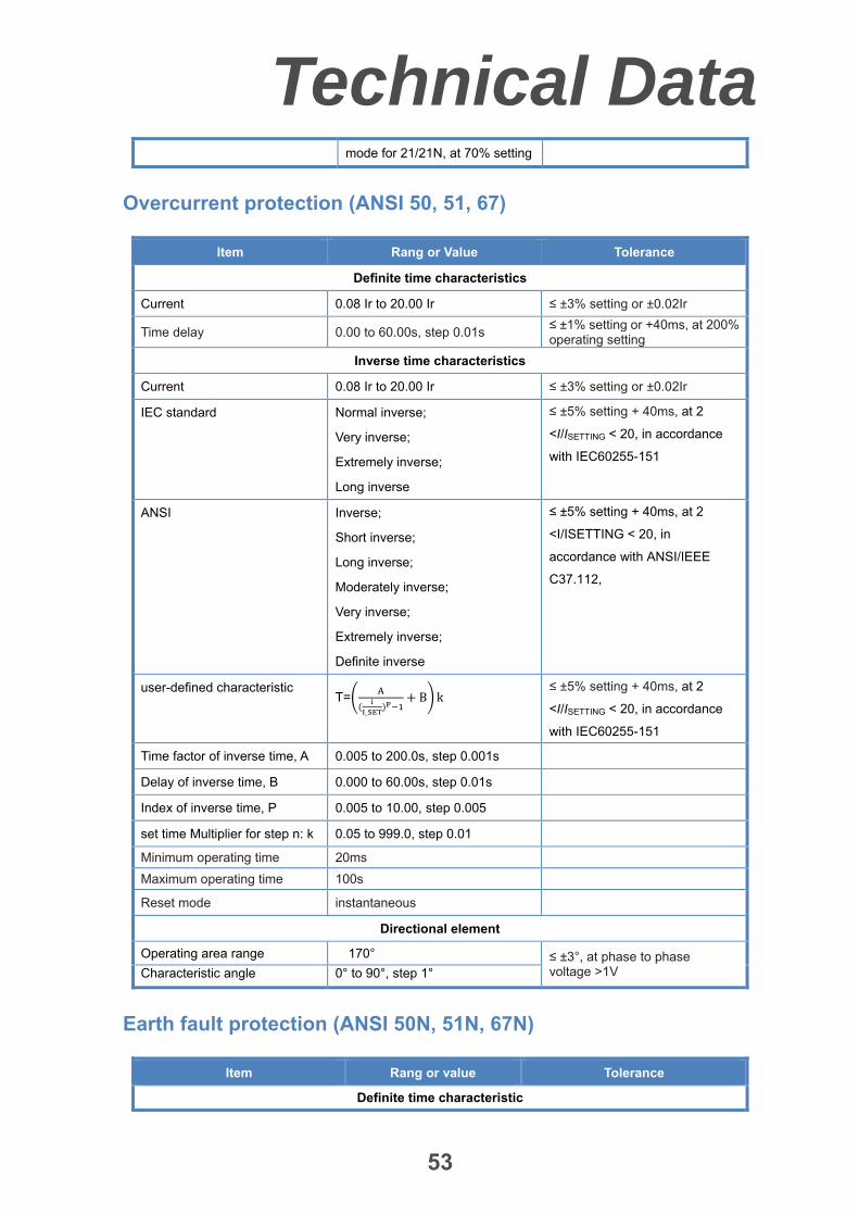
Technical Data
53
mode for 21/21N, at 70% setting
Overcurrent protection (ANSI 50, 51, 67)
Item Rang or Value Tolerance
Definite time characteristics
Current 0.08 Ir to 20.00 Ir ≤ ±3% setting or ±0.02Ir
Time delay 0.00 to 60.00s, step 0.01s ≤ ±1% setting or +40ms, at 200% operating setting
Inverse time characteristics
Current 0.08 Ir to 20.00 Ir ≤ ±3% setting or ±0.02Ir
IEC standard Normal inverse;
Very inverse;
Extremely inverse;
Long inverse
≤ ±5% setting + 40ms, at 2
<I/ISETTING < 20, in accordance
with IEC60255-151
ANSI Inverse;
Short inverse;
Long inverse;
Moderately inverse;
Very inverse;
Extremely inverse;
Definite inverse
≤ ±5% setting + 40ms, at 2
<I/ISETTING < 20, in
accordance with ANSI/IEEE
C37.112,
user-defined characteristic T=
_
B k ≤ ±5% setting + 40ms, at 2
<I/ISETTING < 20, in accordance
with IEC60255-151
Time factor of inverse time, A 0.005 to 200.0s, step 0.001s
Delay of inverse time, B 0.000 to 60.00s, step 0.01s
Index of inverse time, P 0.005 to 10.00, step 0.005
set time Multiplier for step n: k 0.05 to 999.0, step 0.01
Minimum operating time 20ms
Maximum operating time 100s
Reset mode instantaneous
Directional element
Operating area range 170° ≤ ±3°, at phase to phase voltage >1V Characteristic angle 0° to 90°, step 1°
Earth fault protection (ANSI 50N, 51N, 67N)
Item Rang or value Tolerance
Definite time characteristic

Technical Data
54
Current 0.08 Ir to 20.00 Ir ≤ ±3% setting or ±0.02Ir
Time delay 0.00 to 60.00s, step 0.01s ≤ ±1% setting or +40ms, at 200% operating setting
Inverse time characteristics
Current 0.08 Ir to 20.00 Ir ≤ ±3% setting or ±0.02Ir
IEC standard Normal inverse;
Very inverse;
Extremely inverse;
Long inverse
IEC60255-151
≤ ±5% setting + 40ms, at 2
<I/ISETTING < 20
ANSI Inverse;
Short inverse;
Long inverse;
Moderately inverse;
Very inverse;
Extremely inverse;
Definite inverse
ANSI/IEEE C37.112,
≤ ±5% setting + 40ms, at 2
<I/ISETTING < 20
user-defined characteristic T=
_
B k IEC60255-151
≤ ±5% setting + 40ms, at 2
<I/ISETTING < 20
Time factor of inverse time, A 0.005 to 200.0s, step
0.001s
Delay of inverse time, B 0.000 to 60.00s, step 0.01s
Index of inverse time, P 0.005 to 10.00, step 0.005
set time Multiplier for step n: k 0.05 to 999.0, step 0.01
Minimum operating time 20ms
Maximum operating time 100s
Reset mode instantaneous
Directional element
Operating area range of zero
sequence directional element 160°
≤ ±3°, at 3U0≥1V
Characteristic angle 0° to 90°, step 1°
Operating area range of negative
sequence directional element 160°
≤ ±3°, at 3U2≥2V
Characteristic angle 50° to 90°, step 1°
Emergency/backup overcurrent protection (ANSI 50, 51)
Item Rang or Value Tolerance
Definite time characteristics
Current 0.08 Ir to 20.00 Ir ≤ ±3% setting or ±0.02Ir

Technical Data
55
Time delay 0.00 to 60.00s, step 0.01s ≤ ±1% setting or +40ms, at 200% operating setting
Inverse time characteristics
Current 0.08 Ir to 20.00 Ir ≤ ±3% setting or ±0.02Ir
IEC standard Normal inverse;
Very inverse;
Extremely inverse;
Long inverse
≤ ±5% setting + 40ms, at 2
<I/ISETTING < 20, in accordance
with IEC60255-151
ANSI Inverse;
Short inverse;
Long inverse;
Moderately inverse;
Very inverse;
Extremely inverse;
Definite inverse
≤ ±5% setting + 40ms, at 2
<I/ISETTING < 20, in
accordance with ANSI/IEEE
C37.112,
user-defined characteristic T=
_
B k ≤ ±5% setting + 40ms, at 2
<I/ISETTING < 20, in accordance
with IEC60255-151
Time factor of inverse time, A 0.005 to 200.0s, step 0.001s
Delay of inverse time, B 0.000 to 60.00s, step 0.01s
Index of inverse time, P 0.005 to 10.00, step 0.005
set time Multiplier for step n: k 0.05 to 999.0, step 0.01
Minimum operating time 20ms
Maximum operating time 100s
Reset mode instantaneous
Emergency/backup earth fault protection (ANSI 50N, 51N)
Item Rang or value Tolerance
Definite time characteristic
Current 0.08 Ir to 20.00 Ir ≤ ±3% setting or ±0.02Ir
Time delay 0.00 to 60.00s, step 0.01s ≤ ±1% setting or +40ms, at 200% operating setting
Inverse time characteristics
Current 0.08 Ir to 20.00 Ir ≤ ±3% setting or ±0.02Ir
IEC standard Normal inverse;
Very inverse;
Extremely inverse;
Long inverse
≤ ±5% setting + 40ms, at 2
<I/ISETTING < 20, in accordance with
IEC60255-151
ANSI Inverse; ≤ ±5% setting + 40ms, at 2

Technical Data
56
Short inverse;
Long inverse;
Moderately inverse;
Very inverse;
Extremely inverse;
Definite inverse
<I/ISETTING < 20, in accordance
with ANSI/IEEE C37.112,
user-defined characteristic T=
_
B k ≤ ±5% setting + 40ms, at 2
<I/ISETTING < 20, in accordance with
IEC60255-151
Time factor of inverse time, A 0.005 to 200.0s, step
0.001s
Delay of inverse time, B 0.000 to 60.00s, step 0.01s
Index of inverse time, P 0.005 to 10.00, step 0.005
set time Multiplier for step n: k 0.05 to 999.0, step 0.01
Minimum operating time 20ms
Maximum operating time 100s
Reset mode instantaneous
Inrush restraint function
Item Range or value Tolerance
Upper function limit
Max current for inrush restraint
0.25 Ir to 20.00 Ir ≤ ±3% setting value or ±0.02Ir
Ratio of 2nd harmonic current to
fundamental component current
0.10 to 0.45, step 0.01
Cross-block (IL1, IL2, IL3)
(settable time)
0.00s to 60.00 s, step 0.01s ≤ ±1% setting or +40ms
Switch-onto-fault protection (ANSI 50SOTF)
Item Rang or Value Tolerance
Phase current 0.08 Ir to 20.00 Ir ≤ ±3% setting or ±0.02Ir
Zero-sequence current 0.08 Ir to 20.00 Ir ≤ ±3% setting or ±0.02Ir
Time delay of phase overcurrent 0.00s to 60.00s, step 0.01s ≤ ±1% setting or +40ms, at
200% operating setting
Time delay of zero sequence
current
0.00s to 60.00s, step 0.01s ≤ ±1% setting or +40ms, at
200% operating setting

Technical Data
57
Breaker failure protection (ANSI 50 BF)
Item Rang or Value Tolerance
phase current
Negative sequence current
zero sequence current
0.08 Ir to 20.00 Ir ≤ ±3% setting or ±0.02Ir
Time delay of stage 1 0.00s to 32.00 s, step 0.01s ≤ ±1% setting or +25 ms, at
200% operating setting Time delay of stage 2 0.00s to 32.00 s, step 0.01s
Reset time of stage 1 < 20ms
Dead zone protection (ANSI 50DZ)
Item Rang or Value Tolerance
Current 0.08 Ir to 20.00 Ir ≤ ±3% setting or ±0.02Ir
Time delay 0.00s to 32.00s, step 0.01s ≤ ±1% setting or +40 ms, at
200% operating setting
Pole discordance protection (ANSI 50PD)
Item Rang or Value Tolerance
Current 0.08 Ir to 20.00 Ir ≤ ±3% setting or ±0.02Ir
Time delay 0.00s to 60.00s, step 0.01s ≤ ±1% setting or +40 ms, at
200% operating setting
STUB protection (ANSI 50STUB)
Item Rang or Value Tolerance
Current 0.08 Ir to 20.00 Ir ≤ ±3% setting or ±0.02Ir
Time delay 0.00s to 60.00s, step 0.01s ≤ ±1% setting or +40 ms, at
200% operating setting
Undervoltage protection (ANSI 27)
Item Rang or Value Tolerance
Voltage connection Phase-to-phase voltages or
phase-to-earth voltages
≤ ±3 % setting or ±1 V
Phase to earth voltage 5 to 75 V , step 1 V ≤ ±3 % setting or ±1 V
Phase to phase voltage 10 to 150 V, step 1 V ≤ ±3 % setting or ±1 V

Technical Data
58
Reset ratio 1.01 to 2.00, step 0.01 ≤ ±3 % setting
Time delay 0.00 to 120.00 s, step 0.01 s ≤ ±1 % setting or +50 ms, at 80%
operating setting
Current criteria 0.08 to 2.00 Ir ≤ ±3% setting or ±0.02Ir
Reset time ≤ 50 ms
Overvoltage protection (ANSI 59)
Item Rang or Value Tolerance
Voltage connection Phase-to-phase voltages or
phase-to-earth voltages
≤ ±3 % setting or ±1 V
Phase to earth voltage 40 to 100 V, step 1 V ≤ ±3 % setting or ±1 V
Phase to phase voltage 80 to 200 V, step 1 V ≤ ±3 % setting or ±1 V
Reset ratio 0.90 to 0.99, step 0.01 ≤ ±3 % setting
Time delay 0.00 to 60.00 s, step 0.01s ≤ ±1 % setting or +50 ms, at
120% operating setting
Reset time <40ms
Synchro-check and voltage check (ANSI 25)
Item Rang or Value Tolerance
Operating mode Synchronization check:
Synch-check
Energizing check, and synch-check if energizing check failure
Override
Energizing check:
Dead V4 and dead V3Ph
Dead V4 and live V3Ph
Live V4 and dead V3Ph
Voltage threshold of dead line or
bus
10 to 50 V (phase to earth), step
1 V
≤ ± 3 % setting or 1 V
Voltage threshold of live line or
bus
30 to 65 V (phase to earth), step
1 V
≤ ± 3 % setting or 1 V
∆V-measurement Voltage
difference
1 to 40 V (phase-to-earth), steps
1 V
≤ ± 1V
∆f-measurement (f2>f1; f2<f1) 0.02 to 2.00 Hz, step, 0.01 Hz, ≤ ± 20 mHz
∆α-measurement (α2>α1; 1 ° to 80 °, step, 1 ° ≤ ± 3°
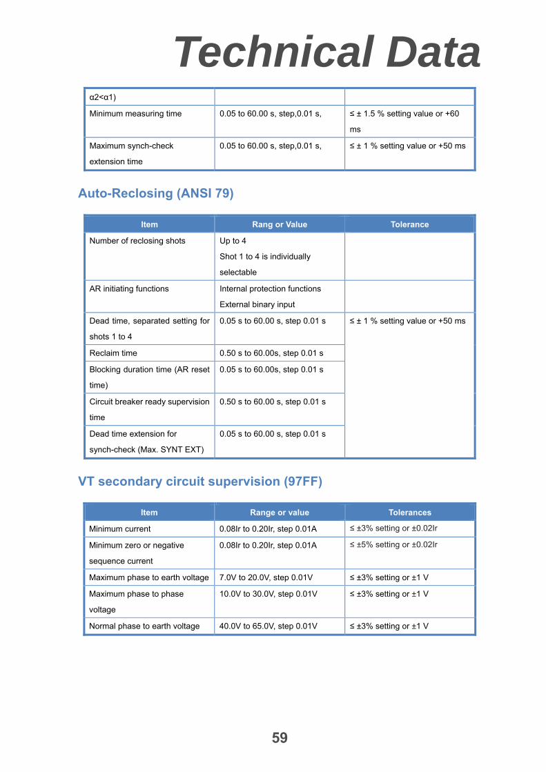
Technical Data
59
α2<α1)
Minimum measuring time 0.05 to 60.00 s, step,0.01 s, ≤ ± 1.5 % setting value or +60
ms
Maximum synch-check
extension time
0.05 to 60.00 s, step,0.01 s, ≤ ± 1 % setting value or +50 ms
Auto-Reclosing (ANSI 79)
Item Rang or Value Tolerance
Number of reclosing shots Up to 4
Shot 1 to 4 is individually
selectable
AR initiating functions Internal protection functions
External binary input
Dead time, separated setting for
shots 1 to 4
0.05 s to 60.00 s, step 0.01 s ≤ ± 1 % setting value or +50 ms
Reclaim time 0.50 s to 60.00s, step 0.01 s
Blocking duration time (AR reset
time)
0.05 s to 60.00s, step 0.01 s
Circuit breaker ready supervision
time
0.50 s to 60.00 s, step 0.01 s
Dead time extension for
synch-check (Max. SYNT EXT)
0.05 s to 60.00 s, step 0.01 s
VT secondary circuit supervision (97FF)
Item Range or value Tolerances
Minimum current 0.08Ir to 0.20Ir, step 0.01A ≤ ±3% setting or ±0.02Ir
Minimum zero or negative
sequence current
0.08Ir to 0.20Ir, step 0.01A ≤ ±5% setting or ±0.02Ir
Maximum phase to earth voltage 7.0V to 20.0V, step 0.01V ≤ ±3% setting or ±1 V
Maximum phase to phase
voltage
10.0V to 30.0V, step 0.01V ≤ ±3% setting or ±1 V
Normal phase to earth voltage 40.0V to 65.0V, step 0.01V ≤ ±3% setting or ±1 V

Ordering
60
Pre-configure schemes
Table 4 Function and hardware of pre-configure scheme for transmission network
Pre-configure version M01 M02 M03 M04
Application Full,2 ends 2 ends 2 ends 2 ends
Breaker arrangement A or B or C A or B or C A or C B
Voltage level(kV) ≥ 230 ≥ 230 ≥ 230 ≥ 230
Line differential protection (87L) 1 1 1 1
Distance protection, 1 or 3 Pole Tripping
Mode (21, 21N) 1 1
Power-swing logic (68) 1 1
Communication scheme for distance
protection (85–21,21N) 1
Communication scheme for directional earth
fault protection (85–67N) 1
Overcurrent protection (50, 51, 67) 1 1 1 1
Earth-fault protection (50N, 51N, 67N) 1 1 1 1
Emergency/backup overcurrent protection
(50, 51) 1 1 1 1
Emergency/backup overcurrent protection
(50N, 51N) 1 1 1 1
Switch-onto-fault protection (50HS) 1 1 1 1
Overload protection (50OL) 1 1 1 1
Overvoltage protection (59) 1 1 1 1
Under voltage protection (27) 1 1 1 1
STUB protection (50STUB) 1 1 1
Breaker failure protection (50BF) 1 1 1
Dead zone protection (50SH-Z) 1 1 1
Poles discordance protection (50PD) 1 1 1
Synchro-check and energizing check (25) 1 1 1
Auto-reclosing, 1 or 3 Pole closing Mode (79) 1 1 1
Single and/or three pole tripping (94) 1 1 1 1
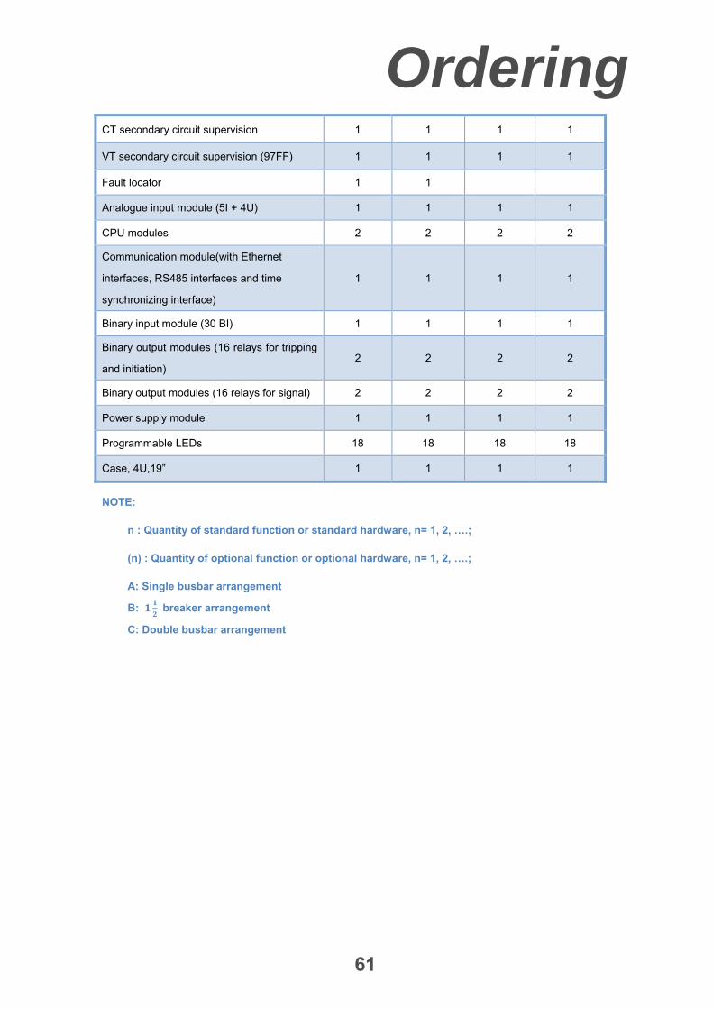
Ordering
61
CT secondary circuit supervision 1 1 1 1
VT secondary circuit supervision (97FF) 1 1 1 1
Fault locator 1 1
Analogue input module (5I + 4U) 1 1 1 1
CPU modules 2 2 2 2
Communication module(with Ethernet
interfaces, RS485 interfaces and time
synchronizing interface)
1 1 1 1
Binary input module (30 BI) 1 1 1 1
Binary output modules (16 relays for tripping
and initiation) 2 2 2 2
Binary output modules (16 relays for signal) 2 2 2 2
Power supply module 1 1 1 1
Programmable LEDs 18 18 18 18
Case, 4U,19” 1 1 1 1
NOTE:
n : Quantity of standard function or standard hardware, n= 1, 2, ….;
(n) : Quantity of optional function or optional hardware, n= 1, 2, ….;
A: Single busbar arrangement
B: breaker arrangement
C: Double busbar arrangement

Ordering
62
Table 5 Function and hardware of pre-configure scheme for sub-transmission network
Pre-configure version N01 N02 N03
Application 2 ends 2 ends 2 ends
Breaker arrangement A or B or C A or B or C B
Voltage level(kV) ≤ 132 ≤ 132 ≤ 132
Line differential protection (87L) 1 1 1
Distance protection, 3 Pole Tripping Mode (21, 21N) 1
Power-swing logic (68) 1
Communication scheme for distance protection (85–
21,21N) 1
Communication scheme for directional earth fault
protection (85–67N) 1
Overcurrent protection (50, 51, 67) 1 1 1
Earth-fault protection (50N, 51N, 67N) 1 1 1
Emergency/backup overcurrent protection (50, 51) 1 1 1
Emergency/backup overcurrent protection (50N,
51N) 1 1 1
Switch-onto-fault protection (50HS) 1 1 1
Overload protection (50OL) 1 1 1
Overvoltage protection (59) 1 1 1
Under voltage protection (27) 1 1 1
STUB protection (50STUB) 1 1
Breaker failure protection (50BF) 1 1
Dead zone protection (50SH-Z) 1 1
Poles discordance protection (50PD) 1 1
Synchro-check and energizing check (25) 1 1
Auto-reclosing, 3 Pole closing Mode (79) 1 1
Three pole tripping (94) 1 1 1
CT secondary circuit supervision 1 1 1
VT secondary circuit supervision (97FF) 1 1 1
Fault locator 1

Ordering
63
Analogue input module (5I + 4U) 1 1 1
CPU modules 1 1 1
Communication module(with Ethernet interfaces,
RS485 interfaces and time synchronizing interface) 1 1 1
Binary input module (30 BI) 1 1 1
Binary output modules (16 relays for tripping and
initiation) 2 2 2
Binary output modules (16 relays for signal) 2 2 2
Power supply module 1 1 1
Programmable LEDs 18 18 18
Case, 4U,19” 1 1 1
NOTE:
n : Quantity of standard function or standard hardware, n= 1, 2, ….;
(n) : Quantity of optional function or optional hardware, n= 1, 2, ….;
A: Single busbar arrangement
B: breaker arrangement
C: Double busbar arrangement

Ordering
64
Ordering code
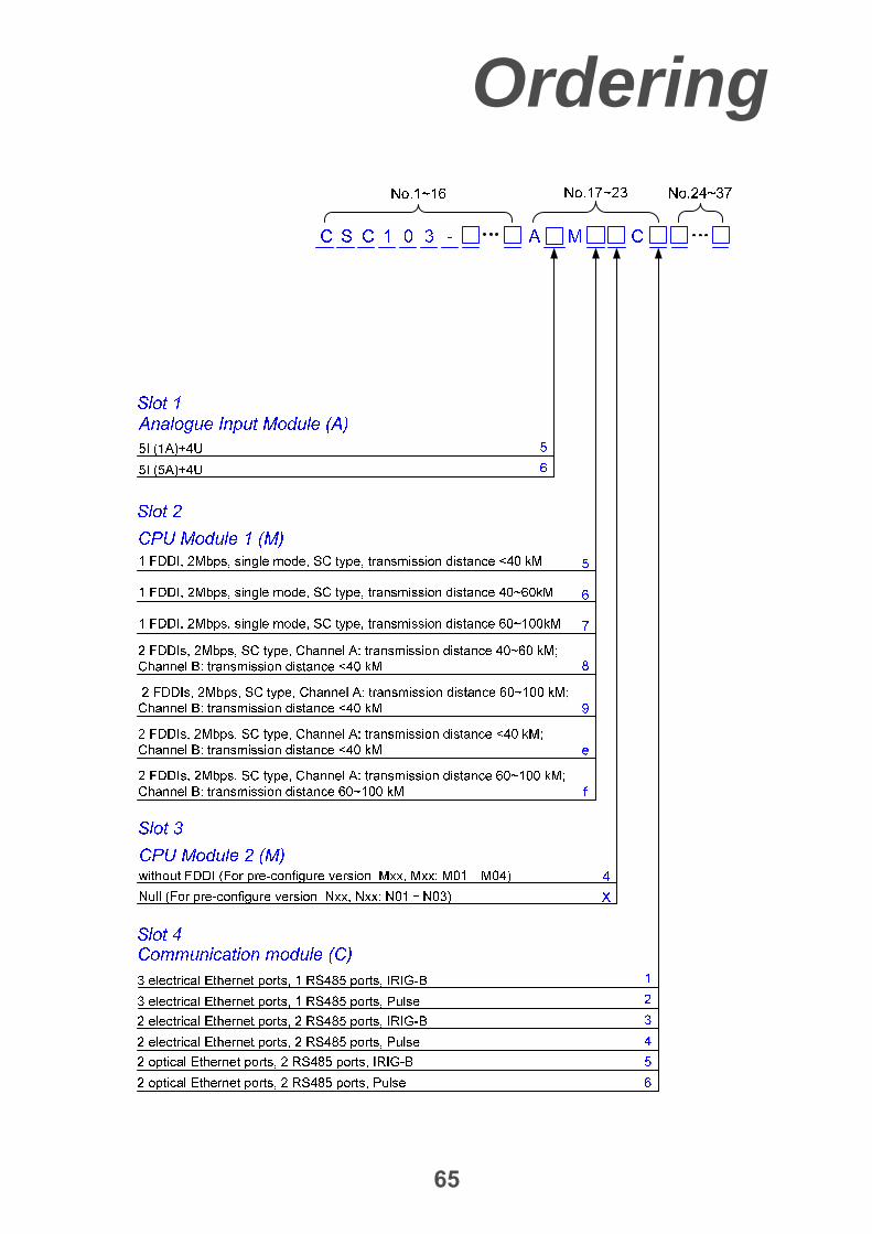
Ordering
65

Ordering
66
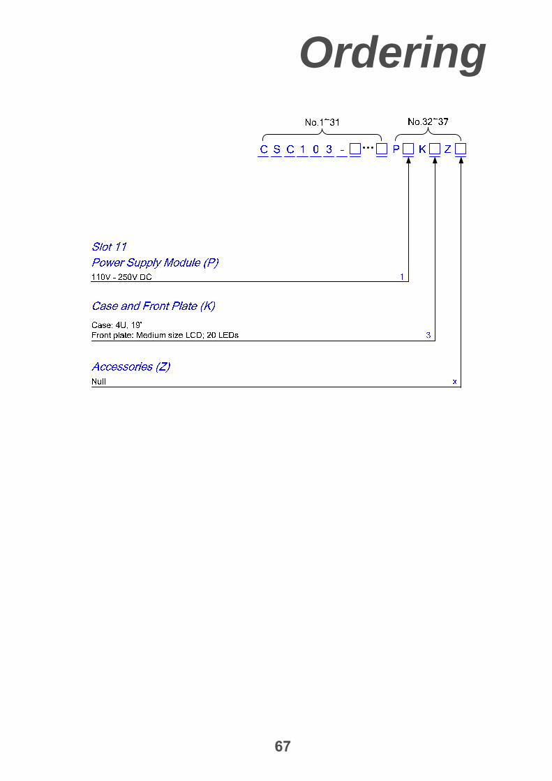
Ordering
67

Address: No.9 Shangdi 4th Street, Haidian District, Beijing, P.R.C. 100085Tel: +86 10 62962554, +86 10 62961515 ext.8998Fax: +86 10 82783625Email:[email protected]: http://www.sf-auto.com