CS-32 Users Manual · 4 . Introduction . Thank you for purchasing the MCS-QuickShot. The...
24
MCS-QuickShot Compact Tactile Graphic Control Surface Users Manual
Transcript of CS-32 Users Manual · 4 . Introduction . Thank you for purchasing the MCS-QuickShot. The...

MCS-QuickShot C o m p ac t Ta c t i l e Gr a p h i c C on t r o l
S u r f ac e
U s e rs Ma n ua l

2
MCS-QuickShot, MCS-3800, MCS-3400 and MCS-3000 are trademarks of JLCooper Electronics. All other brand names are the property of their respective owners. MCS-QuickShot User’s Manual, First Edition (October 8, 2012) Part Number 932098 2004 JLCooper Electronics, 142 Arena Street, El Segundo, CA 90245 USA (310) 322-9990 (310) 335-0110 www.jlcooper.com
3
Ta b l e of C on te n t s Introduction --------------------------------------------------------------- 4
Unpacking ----------------------------------------------------------------- 5
Setup ------------------------------------------------------------------------ 5
Installation and Use ----------------------------------------------------- 6
Connecting the MCS-QuickShot ------------------------------------- 6
Using as a Host Controller --------------------------------------------- 7
Using as an Odetics Controller ---------------------------------------- 8
Initialization ------------------------------------------------------------- 8
Technical Reference --------------------------------------------------- 19
Electrical Connections ----------------------------------------------- 19
Troubleshooting ------------------------------------------------------ 23
Care and Service ----------------------------------------------------- 23
JLCooper Electronics Limited Factory Warranty ------------- 24

4
Introduction
Thank you for purchasing the MCS-QuickShot. The MCS-QuickShot allows you to control video, audio and show control applications in a compact package. No longer do you have to use a mouse and keyboard to cue clips, you can now use a tactile interface with graphic buttons. The MCS-QuickShot has numerous interface options. It has an interface slot to accommodate the MCS-3000 Series Interface Cards. These are available in:
• RS-232 • RS-422 • USB • Ethernet
Additionally, the MCS-QuickShot has an expansion port, which allows it to be connected to an MCS-3000 series controller as a peripheral or to connect to other MCS-3000 series peripherals.

5
Unpacking When you receive your MCS-QuickShot, you should receive the following items:
• MCS-QuickShot • This Users Manual • Universal Power Supply
If you have also purchased an optional MCS-3000 Series Interface card with the MCS-QuickShot, the card may be preinstalled. Please take a moment to register your product at:
http://www.jlcooper.com This will allow us to notify you of important updates and changes to software or features.
Setup If the MCS-QuickShot will be used as a “stand alone” controller, that is without an MCS-3800, an MCS-3000 Series Interface card must be installed. The interface card, which communicates with the host or a controlled device (VTR, switcher, etc), must be installed into the expansion slot.

6
Installation and Use
Connecting the MCS-QuickShot Connecting the MCS-QuickShot is straightforward. If you are using RS-422 to connect to your Odetics compatible decks or video servers, install the RS-422 interface into the expansion slot. Make sure that the jumpers on the RS-422 interface are set to “Machine”. If you are using Ethernet, install the MCS-3000 Series Ethernet Interface into the expansion slot. The Ethernet interface can be connected to your network hub or switch using a standard, straight through, Cat5 cable. The Ethernet interface can also be connected directly to your deck or host computer using a "crossover” cable. The Ethernet interface is capable of operating at 100Mbs or 10Mbs and will auto select the correct port speed. Configuring the IP settings is covered in the Technical Reference section of this manual. If you are using USB to connect to your host computer, install the USB interface into the expansion slot. Configuration and driver installation is covered in the Technical Reference section of this manual. If you are using RS-232 to connect to your host computer, install the RS-232 interface into the expansion slot. Make sure that the jumpers on the RS-232 interface are set to the desired port speed.

7
Using as a Host Controller This section covers operation of the MCS-QuickShot operated with a host such as a computer based application. In this mode of operation, the MCS-QuickShot can be a Master or Slave. In Master operation, the MCS-QuickShot connects directly to the host via an MCS-3000 Series Interface card in the expansion slot. The interface card can be one of the following:
• MCS-3000 Series Ethernet Card #920394 • MCS-3000 Series USB Card #920384 • MCS-3000 Series RS-422 Card #920320 • MCS-3000 Series RS-232 Card #920321
8
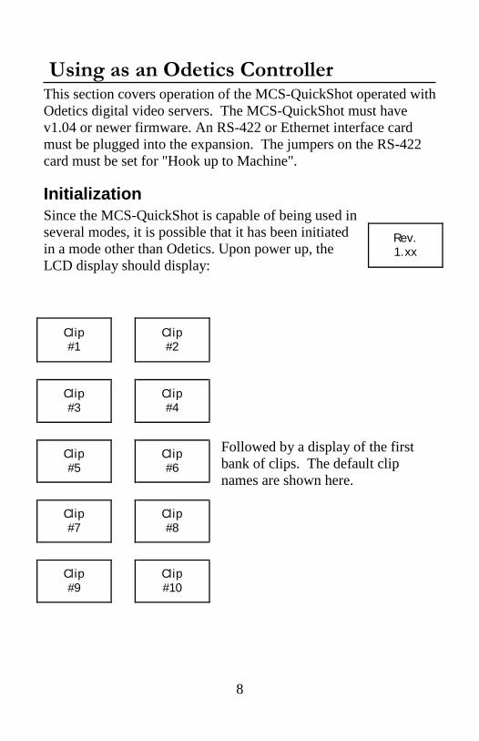
Using as an Odetics Controller This section covers operation of the MCS-QuickShot operated with Odetics digital video servers. The MCS-QuickShot must have v1.04 or newer firmware. An RS-422 or Ethernet interface card must be plugged into the expansion. The jumpers on the RS-422 card must be set for "Hook up to Machine".
Initialization Since the MCS-QuickShot is capable of being used in several modes, it is possible that it has been initiated in a mode other than Odetics. Upon power up, the LCD display should display:
Followed by a display of the first bank of clips. The default clip names are shown here.
Rev. 1.xx
Clip #1 Clip
#2
Clip #3 Clip
#4
Clip #5 Clip
#6
Clip #7 Clip
#8
Clip #9 Clip
#10

9
If the clip names are not displayed, the MCS-QuickShot needs to be placed in Odetics mode. This is done by holding SHIFT and pressing F4. The displays should show the following: Turn the Encoder Knob so button 1 displays “Odetics MODE”. Press the Shift button to save and exit. The MCS-QuickShot is now configured to operate as an Odetics controller. Since the contents of memory are uncertain at this point, it is recommended to initialize the memory for this mode of operation: To clear the contents of memory:
1. Turn off the power switch on the rear. 2. Hold down the F3, F4 and SHIFT buttons. 3. Turn power back on. 4. Release the F3, F4 and SHIFT buttons.
This will initialize clip names to "Clip #1" thru "Clip #80" into the name memory locations. It will also initialize all the clip start and end times to 00:00:00:00.
Host MODE
To Chg -Turn Knob
Press Shift
To Esc

10
Operation After the power-on, the display will show: The MCS-QuickShot has two operational modes when configured as an Odetics controller:
1. Clips Mode 2. Function Mode
This is selected by toggling the SHIFT button. When the SHIFT button is off, the Clips mode is active. When the SHIFT button is illuminated, the Function mode is active.
Clips Mode Clip Buttons The Clips mode allows rapid access to up to 80 clips. The 10 LCD buttons are the Clip buttons. When initialized, they display "Clip #1” thru "Clip #10". Pressing one of the Bank buttons to the right allows access to 10 x 8 = 80 clips. When a clip button is pushed, that clip number is either immediately sent to the Odetics unit, or cued up to be played upon press of the Play button, depending on how clip playout is configured. The button's color will change from orange to green for the duration of the clip's playback. Multiple buttons may be pressed one at a time, and the MCS-QuickShot will cue up those clips for seamless playback. When a button is pressed, it will illuminate different colors based on the state of the clip.
Clip #1 Clip
#2
Clip #3 Clip
#4
Clip #5 Clip
#6
Clip #7 Clip
#8
Clip #9 Clip
#10

11
Amber: Normal unselected state. Flashing Green: Clip is queued and pending Solid Green: Clip is currently being played. Amber: Clip has completed playing
A loop of clips may also be played (see Loop Mode under Page 2 Options below.) Relabeling Clip buttons Each of the 80 clip buttons may have its label changed by the user. Up to 3 lines of 6 characters may be placed on a button. 1. Press the F1 (LABEL) button.
The displays will show: 2. If not already on desired Bank, select a new one, then press the
LCD button to be relabeled. Lets assume that Bank #2, Button #7 is selected.
3. The display will change to:
Button 5 will display the Clip name being edited. The letter "C" has a blinking cursor to indicate current editing position. Rotate the encoder knob to change the character at the current editing position. Press F1 to move the editing position to the previous position. Press F2 to move the editing position to the next position. Press F3 to clear all the characters.
Press Bank & Button Press F1 to
Esc
F1=<- F2=-> F3=Clr
F4=Sve Shift= Escape
B7=Inv B8=Fnt Clip
#14
Clip #15 Clip
#16
Clip #17 Clip
#18
Clip #19 Clip
#20

12
Press F4 to Save the Clip name and exit the clip naming mode. Press SHIFT to exit the clip naming mode without saving the clip name. Press Bank7 to invert the character color. That is to change from black pixels on a clear background to clear pixels on a black background. Press Bank8 to change the font to a larger font. The LCD buttons can accommodate 2 rows of 4 characters.
4. The unit will return to step 1, ready for a new button to be
selected. When you are finished with the relabeling process, press F1 to return to normal operation.
Function Mode Pressing the SHIFT button will switch the MCS-QuickShot to Function mode. The SHIFT button will illuminate to indicate that the MCS-QuickShot is in the Function mode. To return to the Clips mode, press the SHIFT button again.

13
Transport Page After pressing SHIFT, the MCS-QuickShot will display the Transport page. The Transport page is also accessible by pressing the Bank1 button. IN Point saves the incoming timecode at the instant that the button is pressed as the start time for the Save Clip operation. This will send a "In Data Preset" command to the deck. This may be pressed while in the Stop or Play operation, and will signify the start point of a clip. OUT Point saves the incoming timecode at the instant that the button is pressed as the end time for the Save Clip operation. This will send an "Out Data Preset" command to the deck. This may be pressed while in the Stop or Play operation, and will signify the end point of a clip. SAVE CLIP stores the currently saved In Point and Out Point in any clip button you specify. Pressing this will illuminate the button red. At this time, select a Bank, then press a button. The unit will send a Save Segment command to the Odetics, which will cause it to save the In/Out points to the selected clip (segment) number. If the user wishes to not save a clip, pressing the SHIFT button will cancel the operation. STEP and STEP command the deck to step backward or forward by one field. Pressing this button will send a Step Forward command to the deck, which will step the current time forward or backward one frame. These two buttons allow for rapid fine control of position prior to pressing an In Point or Out Point button. Holding down a Step ◄ or Step ► button will cause
IN Point OUT
Point
STEP SAVE
CLIP
STEP

14
a stream of commands to be issued which will cause the deck to play at approximately half play speed. , , , and are record strobe, rewind, fast forward, stop and play commands. They will change from orange to green (or red in the case of the Record button) when the tally from the deck is received. For example, when the deck is in play mode, the MCS-QuickShot will illuminate the Play button.
15
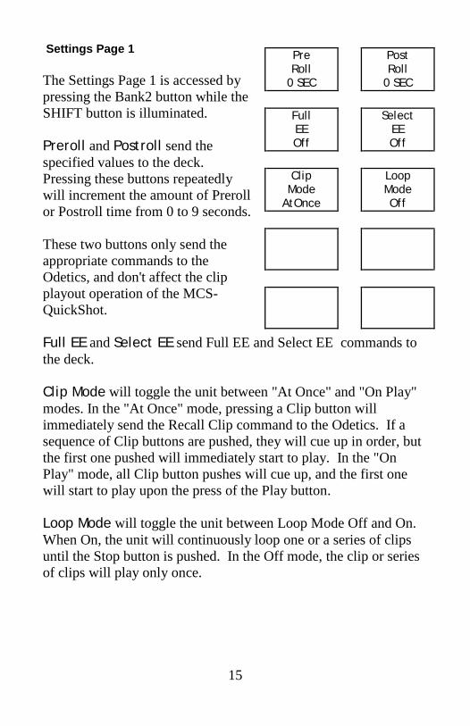
Settings Page 1 The Settings Page 1 is accessed by pressing the Bank2 button while the SHIFT button is illuminated. Preroll and Postroll send the specified values to the deck. Pressing these buttons repeatedly will increment the amount of Preroll or Postroll time from 0 to 9 seconds. These two buttons only send the appropriate commands to the Odetics, and don't affect the clip playout operation of the MCS-QuickShot. Full EE and Select EE send Full EE and Select EE commands to the deck. Clip Mode will toggle the unit between "At Once" and "On Play" modes. In the "At Once" mode, pressing a Clip button will immediately send the Recall Clip command to the Odetics. If a sequence of Clip buttons are pushed, they will cue up in order, but the first one pushed will immediately start to play. In the "On Play" mode, all Clip button pushes will cue up, and the first one will start to play upon the press of the Play button. Loop Mode will toggle the unit between Loop Mode Off and On. When On, the unit will continuously loop one or a series of clips until the Stop button is pushed. In the Off mode, the clip or series of clips will play only once.
Pre Roll
0 SEC
Post Roll
0 SEC
Full EE Off
Select
EE Off
Clip
Mode AtOnce
Loop Mode Off

16
Settings Page 2 The Settings Page 2 is accessed by pressing the Bank3 button while the SHIFT button is illuminated. Pressing the Preview, Review or AutoEdit buttons causes the MCS-QuickShot send these commands to the deck. Auto Mode sends an Auto Mode off or on command. Auto Mode must be on for the Preview/Review/Auto Edit commands to be recognized Chase sends a Chase off or on command to the deck.
Pre- view Re-
view
Auto Edit
Auto Mode On
Chase Mode On

17
Track Arm Page The Track Arm Page is accessed by pressing the Bank3 button while the SHIFT button is illuminated. Pressing the Record Mode button will change the Record Mode in the following manner:
As the button is pushed, the buttons 2 thru 8 will change colors to reflect the new mode. For instance, in Crash Mode, all will be red to indicate that Video and all Audio tracks will be affected by entry into Record. In Insert Mode, the individual Video and Audio buttons may be pressed to allow just the desired track to be recorded to. Off disables the record strobe message from being sent to the deck when the record button is pressed. Crash sets the MCS-QuickShot to send a crash record to the deck when the record button is pressed. Assemble places the deck into assemble record mode. Insert places the deck into insert record mode. Video arms or disarms the video track for insert recording. A1 and A2 arms or disarms the audio tracks for insert recording. These are the analog audio tracks. These are sometimes referred to
Record Mode Off
Video
A1 A2
DA1 DA2
DA3 DA4
Record
Msg Short
Assemble Insert
Off Crash

18
cue tracks. Some decks will interpret these messages as DA1 and DA2 messages and arm those tracks accordingly. DA1, DA2, DA3 and DA4 arms or disarms the digital audio tracks for insert recording. These are sometimes referred to the Hi-Fi tracks. Some decks will interpret the DA1 and DA2 messages as A1 and A2 messages and arm those tracks accordingly. Record Message selects the length of the Edit Preset message between one and two bytes. Notice that selecting the "Short" length turns off the lighting for DA1 thru DA4, indicating that they may not be defined with the short message. When the Record Message is set to short, the MCS-QuickShot sends only the Insert, Assemble, Video, A1 and A2 flags. When the Record Message is set to long, the MCS-QuickShot additionally sends the DA1, DA2, DA3 and DA4 flags.

19
Technical Reference
Electrical Connections
Power The MCS-QuickShot requires a 12 volt DC supply capable of delivering at the minimum, 3 amps. The unit comes with a universal, switching power supply (JLCooper part number 561024) with a power cord appropriate for the country in which the unit was sold. If you need a power cord specific to your location, please contact your local distributor or JLCooper Electronics.
Warning: Using a power supply other than the unit specified can result in damage to the MCS-QuickShot and/or other equipment which is not covered by the JLCooper Factory Warranty.
MCS-3000 Series RS-422 Interface Card The RS-422 Interface is intended for operation with a VTR, controller or a host computer. It provides the advantages of RS-422, which allows for long cable runs. With low loss, low capacitance cable, the RS-422 Interface Card can accommodate cable runs up to 1km. The RS-422 Interface has a female D-Sub connector. The interface can be configured to connect to either a deck or a host. Five jumpers on the interface card configure the pinout. All five jumpers must be places in either the “To Computer” or “To Machine” position. The port is configured to communicate at 38400 bits/sec, 1 start bit, 8 data bits, 1 stop bit and odd parity.

20
MCS-RS422 Interface Pinout
Setting on Card “To Computer” “To Machine”
1 Ground Ground
2 Transmit A Receive A
3 Receive B Transmit B
4 Ground Ground
5 not used not used
6 Ground Ground
7 Transmit B Receive B
8 Receive A Transmit A
9 Ground Ground Note: These signals are at the RS-422 Interface card.
MCS-RS422 Interface In “To Computer” configuration
MCS-RS422 Interface In “To Machine” Configuration
Com
puter M
achine
Com
puter M
achine
21
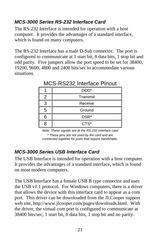
MCS-3000 Series RS-232 Interface Card The RS-232 Interface is intended for operation with a host computer. It provides the advantages of a standard interface, which is found on many computers. The RS-232 Interface has a male D-Sub connector. The port is configured to communicate at 1 start bit, 8 data bits, 1 stop bit and odd parity. Five jumpers allow the port speed to be set for 38400, 19200, 9600, 4800 and 2400 bits/sec to accommodate various situations.
MCS-3000 Series USB Interface Card The USB Interface is intended for operation with a host computer. It provides the advantages of a standard interface, which is found on most modern computers. The USB Interface has a female USB B type connector and uses the USB v1.1 protocol. For Windows computers, there is a driver that allows the device with this interface card to appear as a com port. This driver can be downloaded from the JLCooper support web site, http://www.jlcooper.com/pages/downloads.html. With the driver, the virtual com port is configured to communicate at 38400 bits/sec, 1 start bit, 8 data bits, 1 stop bit and no parity.
MCS-RS232 Interface Pinout 1 DCD*
2 Transmit
3 Receive
5 Ground
6 DSR*
8 CTS* Note: These signals are at the RS-232 Interface card
* These pins are not used by the card and are connected together for ports that require handshake.

22
MCS-3000 Series Ethernet Interface Card The Ethernet Interface is intended for operation with a host computer. It provides the advantages of a standard interface, long cable runs, use over private/public/wired/wireless networks, the ability of being shared among computers and the ability to work with any platform that supports TCP/IP. The Ethernet interface can be used to communicate with certain decks with Ethernet ports such as the Doremi V1 or MCS. Additionally, the Ethernet interface can be used to communicate with software applications specifically written to support the Ethernet Interface. Consult your software’s users documentation for details on how to configure the software. To configure the MCS-QuickShot Ethernet settings, an Ethernet Interface card must be in the expansion slot. You can verify this by visually checking the expansion slot for the presence of an Ethernet card. To set the IP address, press SHIFT + F1 during power on to access the configuration page and follow the on screen instructions. Note: You must power cycle the MCS-QuickShot for the Ethernet settings to take effect.

23
Troubleshooting If for some reason the MCS-QuickShot does not give you the expected results, take a moment to do some investigating. The most important concept is that you have your MCS-QuickShot connected properly as outlined in Installation and Use. Take a moment to double check your setup. A common problem is forgetting to turn the power switch on or turning the unit on after the software application has launched. In addition, the JLCooper website (www.jlcooper.com) will contain up to date information on drivers, applications and troubleshooting. If all else fails, you can contact the JLCooper Service Department at: [email protected].
Care and Service If properly cared for, your MCS-QuickShot should provide years of troublefree performance. While the MCS-QuickShot is built in a rugged metal enclosure, please avoid dropping the MCS-QuickShot. Clean with a soft, damp cloth. Do not allow liquids, dust or other foreign matter to get inside the unit. There are no user-serviceable parts in the MCS-QuickShot. Please refer to the JLCooper Electronics Limited Factory Warranty on the following page for detailed warranty and service information.
24
JLCooper Electronics Limited Factory Warranty JLCooper Electronics ("JLCooper") warrants this product to be free of defects in materials or workmanship for a period of 12 months from the date of purchase. This warranty is non-transferable and the benefits apply only to the original owner. Proof of purchase in the form of an itemized sales receipt is required for warranty coverage. To receive service under this warranty, customers in the United States should contact the JLCooper factory at (310) 322-9990 and talk to a service technician. If necessary, a Return Authorization number may be issued. For our customers outside the United States, it is recommended that you first contact your Dealer or Distributor, since they may offer their own service or support policy. If local support is not obtainable, please send a FAX to JLCooper's Service Department at +1 310 335 0110 with a detailed description of the service required. Upon issuance of return authorization, the product should be packed in the original shipping materials and shipped prepaid and insured to: Service Department, JLCooper Electronics, 142 Arena Street, El Segundo, CA 90245. Please include the following: copy of the sales receipt, your name and address (no P.O. Boxes, please), a brief description of the problem, and any other related items discussed with the service department and considered necessary to evaluate the product or effect a repair. The return authorization number must be clearly written on the outside of the package. JLCooper will at its option, without charge for parts or labor, either repair or replace the defective part(s) or unit. Shipping costs are not covered by this warranty. JLCooper's normal repair turn around time at the factory is approximately 15 business days from receipt of product to shipping. Your actual turn around time will include return shipping. Actual turn around time will vary depending upon many factors including the repeatability of the customer's reported complaint, the availability of parts required for repair, the availability of related products needed to evaluate the product if necessary. Priority services are available at additional cost. These should be discussed with the service technician at the time the return authorization is issued. This warranty provides only the benefits specified and does not cover defects or repairs needed as result of acts beyond the control of JLCooper including but not limited to: abuse, damage by accident/negligence, damage from using incorrect power supply, modification, alteration, improper use, unauthorized servicing, tampering, or failure to operate in accordance with the procedures outlined in the owner's manual; nor for natural or man-made events such as, but not limited to flooding, lightning, tornadoes, earthquake, fire, civil unrest, war, terrorism, etc. THE DURATION OF ANY OTHER WARRANTIES, WHETHER EXPRESSED OR IMPLIED, INCLUDING BUT NOT LIMITED TO THE IMPLIED WARRANTY OF MERCHANTABILITY, IS LIMITED TO THE DURATION OF THE EXPRESS WARRANTY HEREIN. JLCOOPER HEREBY EXCLUDES INCIDENTAL AND CONSEQUENTIAL DAMAGES, INCLUDING BUT NOT LIMITED TO: LOSS OF TIME, INCONVENIENCE, DELAY IN PERFORMANCE OF THIS WARRANTY, THE LOSS OF USE OF THE PRODUCT OR COMMERCIAL LOSS, AND FOR BREACH OF ANY EXPRESS OR IMPLIED WARRANTY OF MERCHANT- ABILITY APPLICABLE TO THIS PRODUCT. JLCOOPER SHALL NOT BE LIABLE FOR DAMAGES OR LOSS RESULTING FROM THE NEGLIGENT OR INTENTIONAL ACTS OF THE SHIPPER OR HIS CONTRACT AFFILIATES. THE CUSTOMER SHOULD CONTACT THE SHIPPER FOR PROPER CLAIMS PROCEDURES IN THE EVENT OF DAMAGE OR LOSS RESULTING FROM SHIPMENT. THIS WARRANTY SHALL BE GOVERENED BY THE LAWS OF THE STATE OF CALIFORNIA.