
CS-195+ info Sheet...3M Fire Barrier Caulk or Putty Introduction This installation guide highlights...
16
Fire Barrier Composite Sheet CS-195+ Installation Guide For Telecommunications and Electrical Applications 3
Transcript of CS-195+ info Sheet...3M Fire Barrier Caulk or Putty Introduction This installation guide highlights...
Fire BarrierComposite Sheet CS-195+
Installation Guide For Telecommunications and Electrical Applications
3
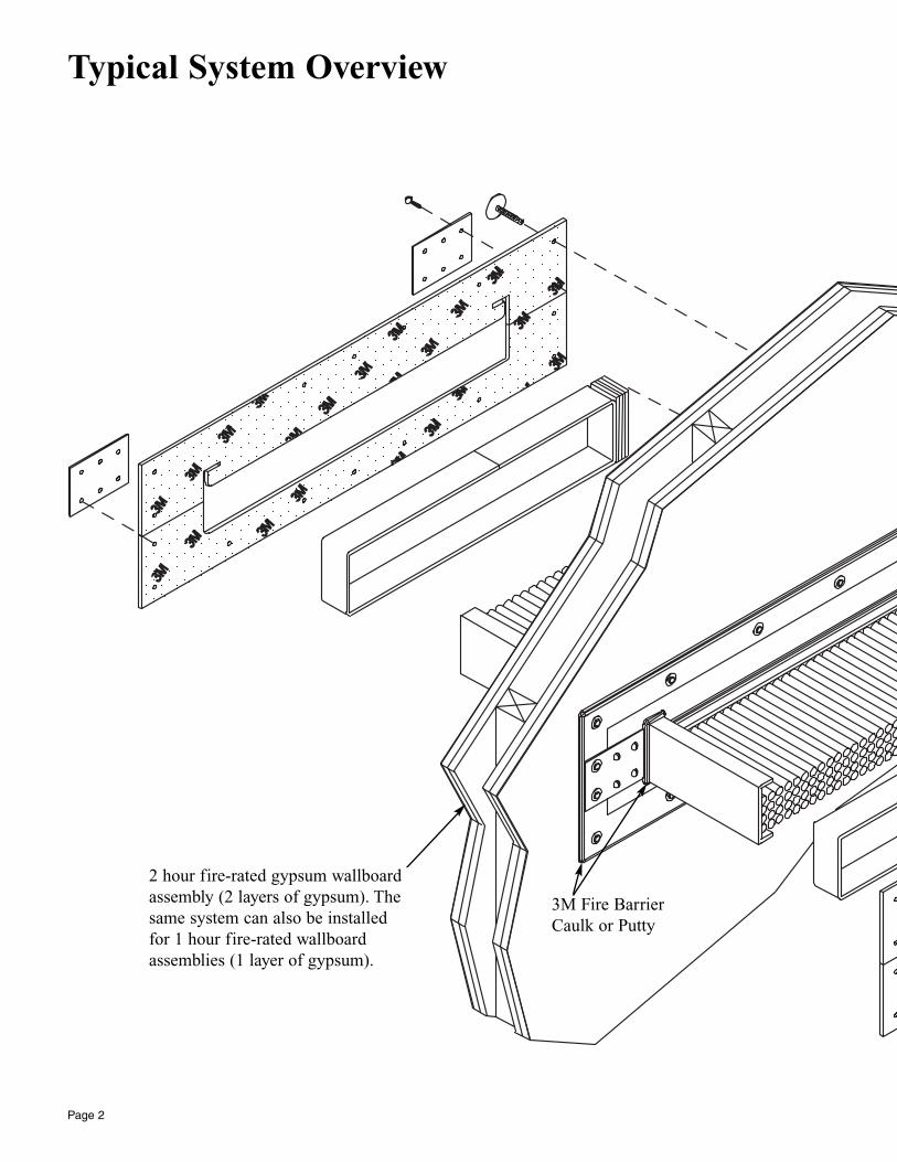
Typical System Overview
Page 2
2 hour fire-rated gypsum wallboardassembly (2 layers of gypsum). Thesame system can also be installedfor 1 hour fire-rated wallboardassemblies (1 layer of gypsum).
3M Fire BarrierCaulk or Putty
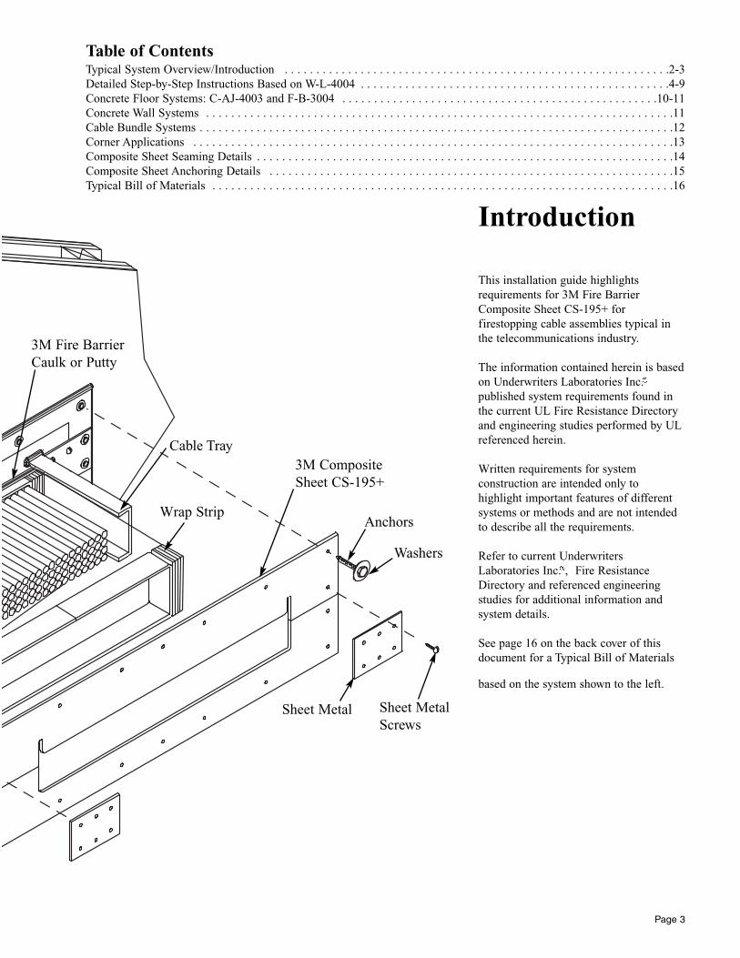
Introduction
This installation guide highlights requirements for 3M Fire BarrierComposite Sheet CS-195+ for firestopping cable assemblies typical inthe telecommunications industry.
The information contained herein is basedon Underwriters Laboratories Inc. published system requirements found inthe current UL Fire Resistance Directoryand engineering studies performed by ULreferenced herein.
Written requirements for system construction are intended only to highlight important features of differentsystems or methods and are not intendedto describe all the requirements.
Refer to current UnderwritersLaboratories Inc. ‚ Fire ResistanceDirectory and referenced engineeringstudies for additional information andsystem details.
See page 16 on the back cover of thisdocument for a Typical Bill of Materials
based on the system shown to the left.
Page 3
3M Fire BarrierCaulk or Putty
Cable Tray
Wrap Strip
Sheet Metal Sheet MetalScrews
Anchors
3M CompositeSheet CS-195+
Table of ContentsTypical System Overview/Introduction . . . . . . . . . . . . . . . . . . . . . . . . . . . . . . . . . . . . . . . . . . . . . . . . . . . . . . . . . . . . .2-3Detailed Step-by-Step Instructions Based on W-L-4004 . . . . . . . . . . . . . . . . . . . . . . . . . . . . . . . . . . . . . . . . . . . . . . . . .4-9Concrete Floor Systems: C-AJ-4003 and F-B-3004 . . . . . . . . . . . . . . . . . . . . . . . . . . . . . . . . . . . . . . . . . . . . . . . . . .10-11Concrete Wall Systems . . . . . . . . . . . . . . . . . . . . . . . . . . . . . . . . . . . . . . . . . . . . . . . . . . . . . . . . . . . . . . . . . . . . . . . . . .11Cable Bundle Systems . . . . . . . . . . . . . . . . . . . . . . . . . . . . . . . . . . . . . . . . . . . . . . . . . . . . . . . . . . . . . . . . . . . . . . . . . . .12Corner Applications . . . . . . . . . . . . . . . . . . . . . . . . . . . . . . . . . . . . . . . . . . . . . . . . . . . . . . . . . . . . . . . . . . . . . . . . . . . .13Composite Sheet Seaming Details . . . . . . . . . . . . . . . . . . . . . . . . . . . . . . . . . . . . . . . . . . . . . . . . . . . . . . . . . . . . . . . . . .14Composite Sheet Anchoring Details . . . . . . . . . . . . . . . . . . . . . . . . . . . . . . . . . . . . . . . . . . . . . . . . . . . . . . . . . . . . . . . .15Typical Bill of Materials . . . . . . . . . . . . . . . . . . . . . . . . . . . . . . . . . . . . . . . . . . . . . . . . . . . . . . . . . . . . . . . . . . . . . . . . .16
Washers
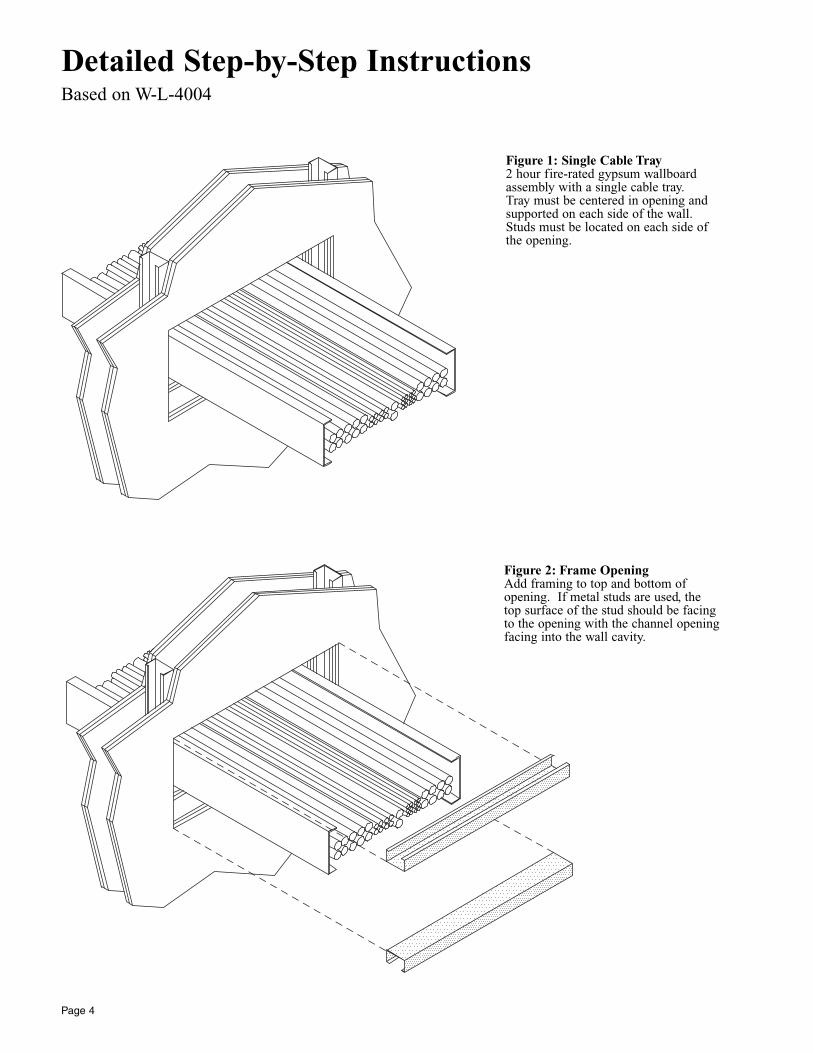
Detailed Step-by-Step InstructionsBased on W-L-4004
Figure 1: Single Cable Tray2 hour fire-rated gypsum wallboardassembly with a single cable tray. Tray must be centered in opening andsupported on each side of the wall.Studs must be located on each side ofthe opening.
Page 4
Figure 2: Frame OpeningAdd framing to top and bottom ofopening. If metal studs are used, thetop surface of the stud should be facingto the opening with the channel openingfacing into the wall cavity.
Page 5
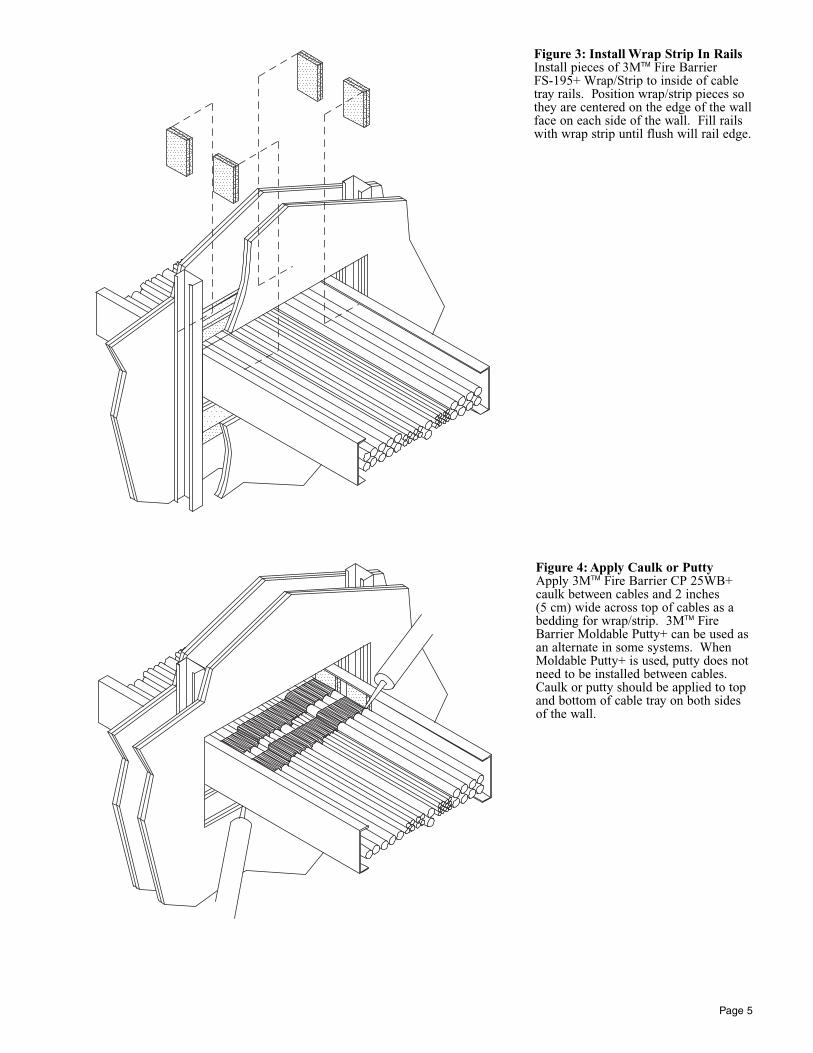
Figure 3: Install Wrap Strip In RailsInstall pieces of 3MTM Fire Barrier FS-195+ Wrap/Strip to inside of cabletray rails. Position wrap/strip pieces sothey are centered on the edge of the wallface on each side of the wall. Fill railswith wrap strip until flush will rail edge.
Figure 4: Apply Caulk or PuttyApply 3MTM Fire Barrier CP 25WB+caulk between cables and 2 inches (5 cm) wide across top of cables as abedding for wrap/strip. 3MTM FireBarrier Moldable Putty+ can be used asan alternate in some systems. WhenMoldable Putty+ is used, putty does notneed to be installed between cables.Caulk or putty should be applied to topand bottom of cable tray on both sidesof the wall.
Page 6
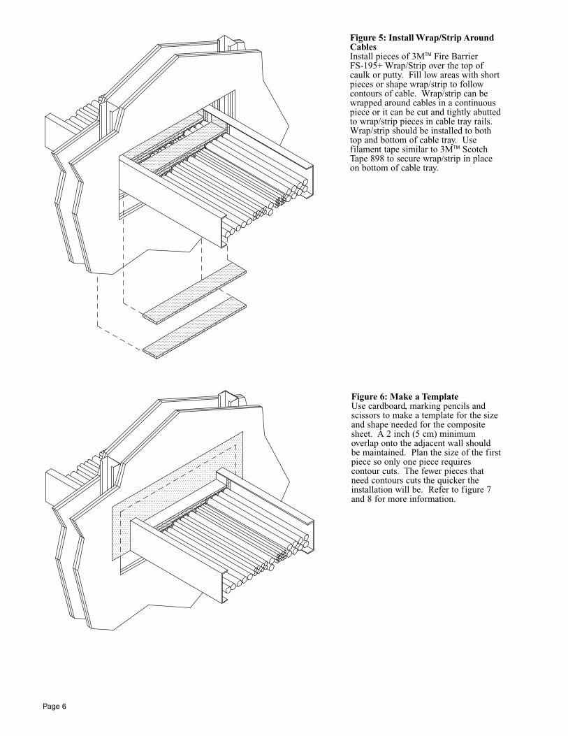
Figure 5: Install Wrap/Strip AroundCablesInstall pieces of 3MTM Fire Barrier FS-195+ Wrap/Strip over the top ofcaulk or putty. Fill low areas with shortpieces or shape wrap/strip to follow contours of cable. Wrap/strip can bewrapped around cables in a continuouspiece or it can be cut and tightly abuttedto wrap/strip pieces in cable tray rails.Wrap/strip should be installed to bothtop and bottom of cable tray. Use filament tape similar to 3MTM ScotchTape 898 to secure wrap/strip in placeon bottom of cable tray.
Figure 6: Make a TemplateUse cardboard, marking pencils andscissors to make a template for the sizeand shape needed for the compositesheet. A 2 inch (5 cm) minimum overlap onto the adjacent wall shouldbe maintained. Plan the size of the firstpiece so only one piece requires contour cuts. The fewer pieces thatneed contours cuts the quicker theinstallation will be. Refer to figure 7and 8 for more information.
Page 7
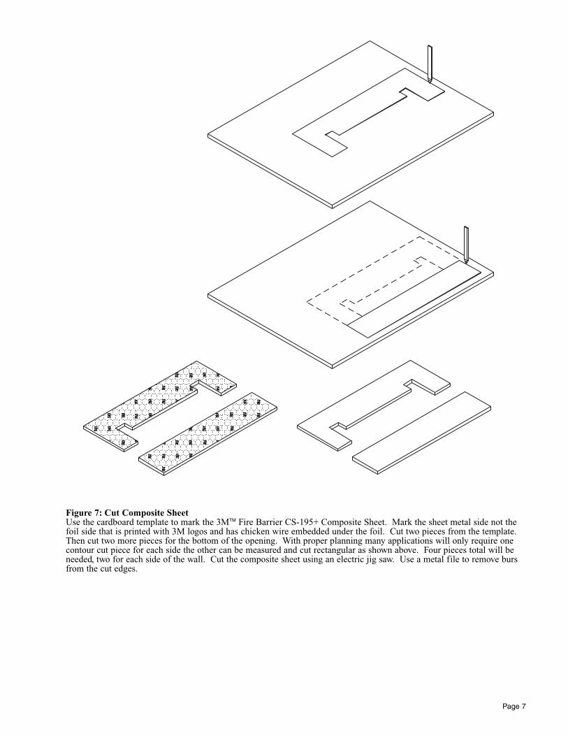
Figure 7: Cut Composite SheetUse the cardboard template to mark the 3MTM Fire Barrier CS-195+ Composite Sheet. Mark the sheet metal side not thefoil side that is printed with 3M logos and has chicken wire embedded under the foil. Cut two pieces from the template.Then cut two more pieces for the bottom of the opening. With proper planning many applications will only require onecontour cut piece for each side the other can be measured and cut rectangular as shown above. Four pieces total will beneeded, two for each side of the wall. Cut the composite sheet using an electric jig saw. Use a metal file to remove bursfrom the cut edges.
Page 8
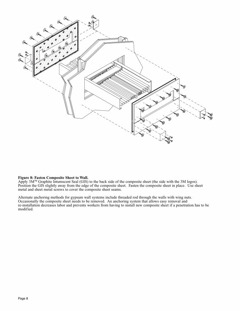
Figure 8: Fasten Composite Sheet to Wall.Apply 3MTM Graphite Intumscent Seal (GIS) to the back side of the composite sheet (the side with the 3M logos).Position the GIS slightly away from the edge of the composite sheet. Fasten the composite sheet in place. Use sheetmetal and sheet metal screws to cover the composite sheet seams.
Alternate anchoring methods for gypsum wall systems include threaded rod through the walls with wing nuts.Occasionally the composite sheet needs to be removed. An anchoring system that allows easy removal and re-installation decreases labor and prevents workers from having to install new composite sheet if a penetration has to bemodified.
Page 9
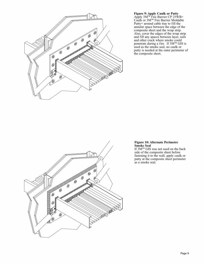
Figure 9: Apply Caulk or PuttyApply 3MTM Fire Barrier CP 25WB+Caulk or 3MTM Fire Barrier MoldablePutty+ around cable tray to fill theannular space between the edge of thecomposite sheet and the wrap strip.Also, cover the edges of the wrap stripand fill any spaces between layer, railsand other crack where smoke could penetrate during a fire. If 3MTM GIS isused as the smoke seal, no caulk orputty is needed at the outer perimeter ofthe composite sheet.
Figure 10: Alternate PerimeterSmoke SealIf 3MTM GIS was not used on the backside of the composite sheet before fastening it to the wall, apply caulk orputty at the composite sheet perimeteras a smoke seal.
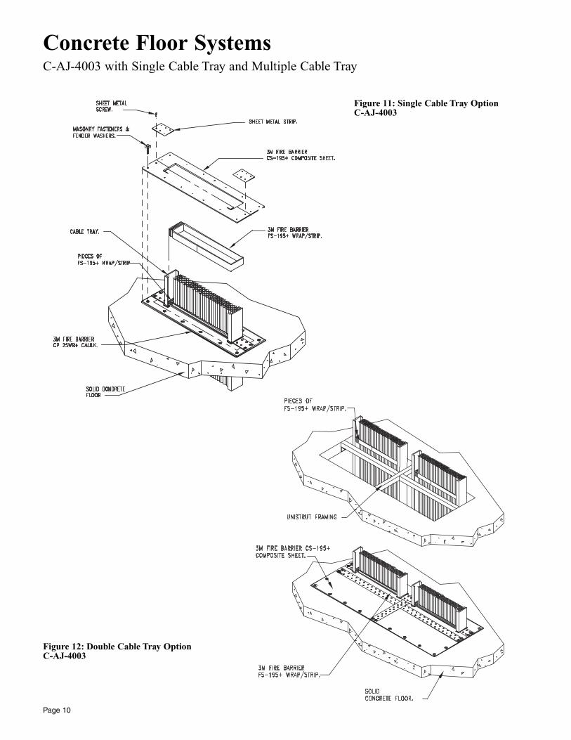
Concrete Floor SystemsC-AJ-4003 with Single Cable Tray and Multiple Cable Tray
Page 10
Figure 11: Single Cable Tray OptionC-AJ-4003
Figure 12: Double Cable Tray OptionC-AJ-4003
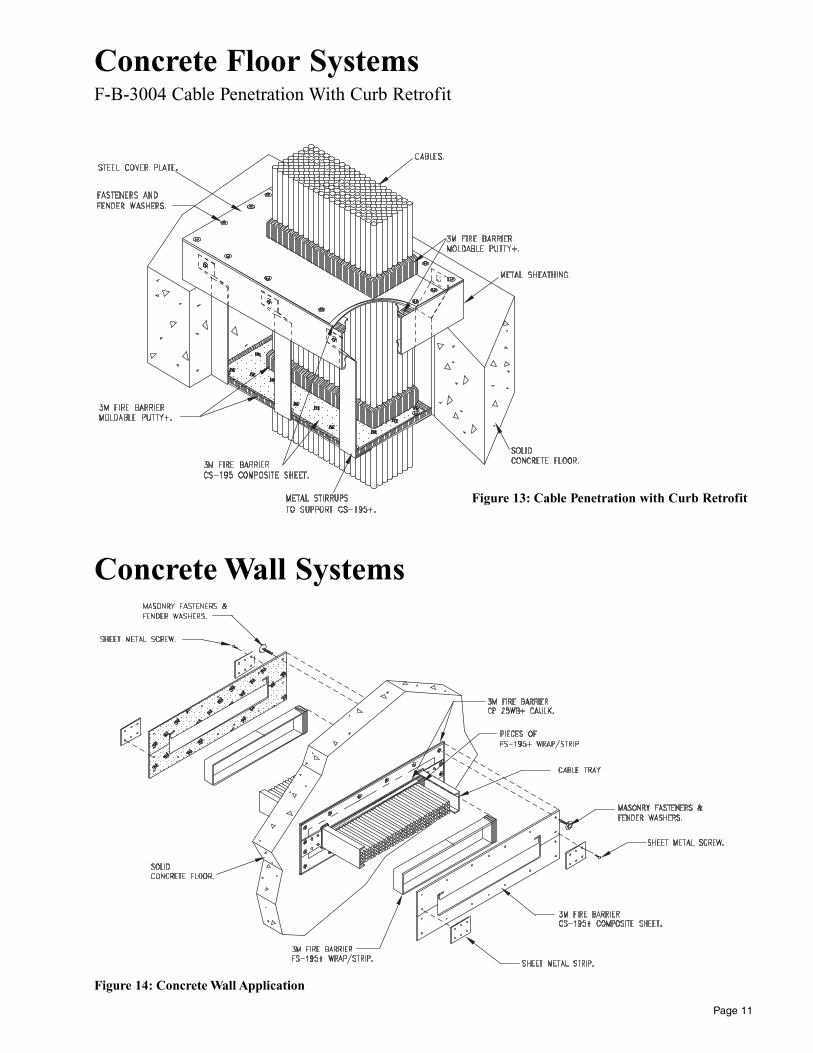
Concrete Floor SystemsF-B-3004 Cable Penetration With Curb Retrofit
Page 11
Figure 13: Cable Penetration with Curb Retrofit
Figure 14: Concrete Wall Application
Concrete Wall Systems
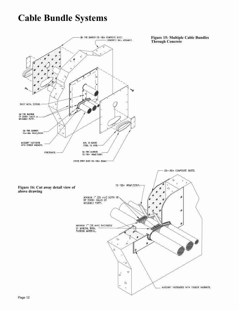
Cable Bundle Systems
Page 12
Figure 15: Multiple Cable Bundles Through Concrete
Figure 16: Cut away detail view of above drawing
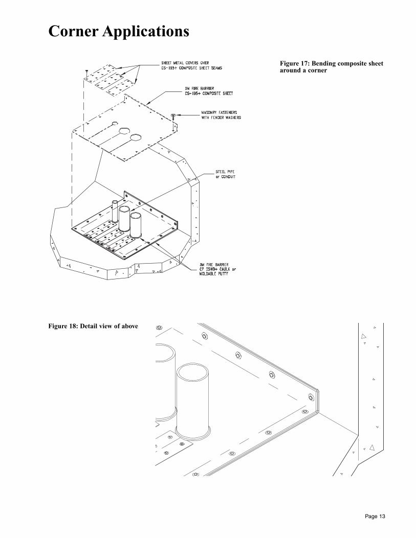
Corner Applications
Page 13
Figure 17: Bending composite sheetaround a corner
Figure 18: Detail view of above
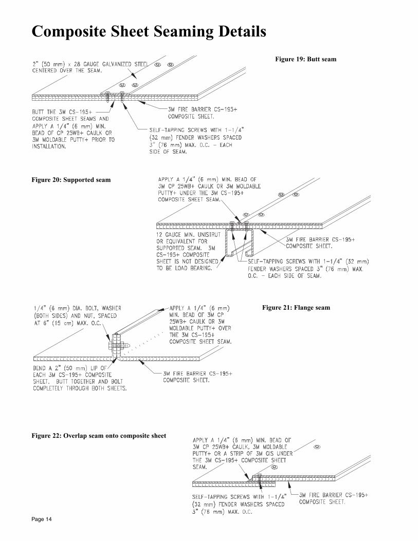
Composite Sheet Seaming Details
Page 14
Figure 19: Butt seam
Figure 20: Supported seam
Figure 21: Flange seam
Figure 22: Overlap seam onto composite sheet
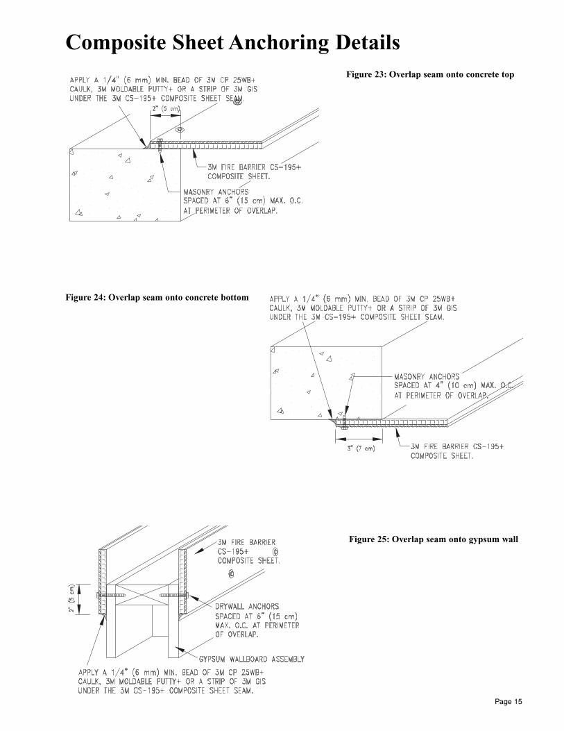
Composite Sheet Anchoring Details
Page 15
Figure 23: Overlap seam onto concrete top
Figure 24: Overlap seam onto concrete bottom
Figure 25: Overlap seam onto gypsum wall
Printed in U.S.A.
© 3M 2000 98-0400-4993-8 May 2000
Specified Constreuction Products Department
3M Center 225-4S-08St. Paul, MN 55144-1000(800) 328-1687
3
Product Size Packaging1 Each/box Bulk (Greater
than 10 each)
CS-195+ 16 in. x 28 in. X X(406.4 mm x 711.2 mm)24 in. x 36 in. X X(609.6 mm x 914.4 mm)36 in. x 36 in. X X(914.4 mm x 914.4 mm)36 in. x 41 in. X X(914.4 mm x 1041.4 mm)28 in. x 52 in. X X(711.2 mm x 1320.8 mm)
Warranty and Limited Remedy. This product will be free from defects in materials and manufacture for a period of ninety (90) days fromdate of purchase. 3M MAKES NO OTHER WARRANTIES INCLUDING, BUT NOT LIMITED TO, ANY IMPLIED WARRANTY OF MERCHANTABILITY OR FITNESS FOR A PARTICULAR PURPOSE. User is responsible for determining whether the 3M product is fitfor a particular purpose and suitable for a user’s method of application. If this 3M product is proved to be defective within the warrantyperiod stated above, your exclusive remedy and 3M’s sole obligation shall be, at 3M’s option, to replace or repair the 3M product or refundthe purchase price of the 3M product.
Limitation of Liability. Except where prohibited by law, 3M will not be liable for any loss or damages arising from the use of this3M product, whether direct, indirect, special, incidental, or consequential, regardless of the legal theory asserted, including warranty, contract, negligence or strict liability.
Product Ordering InformationTypical Bill of MaterialsBelow is a list of 3M Firestopping Products, other materials and tools needed to install 3MTM Fire Barrier CS-195+Composite Sheet systems.
All products are not used in every system. For example either 3MTM Fire Barrier CP 25WB+ Caulk or 3MTM Fire BarrierMoldable Putty+ will be used in particular system but not both. 3MTM Fire Barrier FS-195+ Wrap/Strip is used in all sys-tems. 3MTM ScotchTM Filament Tape 898 is only used to temporarily secure wrap strip to the bottom of cable trays beforecomposite sheet is installed.
Material Sold by 3M1. 3MTM Fire Barrier CS-195+ Composite Sheet2. 3MTM Fire Barrier FS-195+ Wrap/Strip3. 3MTM Fire Barrier CP 25WB+ Caulk4. 3MTM Fire Barrier Moldable Putty+ Stix (MPS-2+)5. 3MTM Graphite Intumescent Seal (GIS)6. ScotchTM Filament Tape 898
Materials Not Sold by 3M1. Sheet metal2. #10 sheet metal screws3. 1/4-20 by 1 inch H.H. cap screws4. 1-1/4 inch fender washers5. Masonry or drywall anchors6. Threaded rod and wings nuts (alternate to item 5)7. Cardboard
Tools Needed1. C-Clamp, 6 inch (15 cm)2. Contour Gage3. Scissors4. Electric Drill with 3/8 inch (9 mm) bit5. Electric nibbler6. Metal file7. Perforating punch, 7/16 inch (11 mm)8. Rachet box wrench, 9/16 inch (14 mm)9. Electric jig saw10. Safety Glasses11. Work Gloves
Product Fl. oz. Cubic Units perInches Carton
CP 25WB+ Caulk:Cartridge 10.5 (310 mL) 19.0 12Sausage 20.0 (591 mL) 36.0 10Cartridge 27.0 (798 mL) 48.7 62 Gallon 256.0 (7.57 L) 462.0 15 Gallon 640.0 (19 L) 1155.0 1
Product Size Units perCarton
GIS 1/16 in. x 1/2 in. x 51 ft. 10 rolls(1.6 mm x 12.7 mm x 15.24 m)
Product Size Units perCarton
FS-195+ 2 in. x 24 in. 10 rollsWrap/ (50.8 mm x 609.6 mm)Strip
1 in. x 24 in. 20 rolls(25.4 mm x 609.6 mm)
Product Size Cubic Units perInches Carton
MPS-2+ 1.6 in. x 11 in. 21.2 10 rolls(40.6 mm x 279 mm)


![3M Brand Fire Barrier CP-25WB173.247.243.154/~mavosystems/files/duct/SDS 3M BRAND FIRE BARR… · 1.35 [RefStd: WATER-I] Complete No Data Available Not Applicable No Data Available](https://static.fdocuments.in/doc/165x107/5b8bf66409d3f240638c2d6f/3m-brand-fire-barrier-cp-25wb173247243154mavosystemsfilesductsds-3m-brand.jpg)


