Cryopreservation Manual - Fisher...
32
Cryopreservation Manual Analyze • Detect • Measure • Control TM A Guide to Cryopreservation Techniques Dr. Kelvin G. M. Brockbank James C. Covault Dr. Michael J. Taylor
-
Upload
nguyentuyen -
Category
Documents
-
view
233 -
download
2
Transcript of Cryopreservation Manual - Fisher...
Cryopreservation Manual
Analyze • Detect • Measure • ControlTM
A Guide to Cryopreservation Techniques
Dr. Kelvin G. M. Brockbank
James C. Covault
Dr. Michael J. Taylor

iii
TABLE OF CONTENTS
ABOUT THE AUTHORS . . . . . . . . . . . . . . . . . . . . . . . . . . . . . . . . . . . . . . . . . . . . . . . . . . . . . . . . . . . . . . . . . . . . . . . . . . . . IV
PREFACE . . . . . . . . . . . . . . . . . . . . . . . . . . . . . . . . . . . . . . . . . . . . . . . . . . . . . . . . . . . . . . . . . . . . . . . . . . . . . . . . . . . . . . . V
PART 1: CRYOBIOLOGY AND CRYOPRESERVATION . . . . . . . . . . . . . . . . . . . . . . . . . . . . . . . . . . . . . . . . . . . . . . . . . . . . . . 1
Variables to Optimize . . . . . . . . . . . . . . . . . . . . . . . . . . . . . . . . . . . . . . . . . . . . . . . . . . . . . . . . 1Cryoprotective Agents . . . . . . . . . . . . . . . . . . . . . . . . . . . . . . . . . . . . . . . . . . . . . . . . . . . . . . . 2
Vitrification . . . . . . . . . . . . . . . . . . . . . . . . . . . . . . . . . . . . . . . . . . . . . . . . . . . . . . . . . . . . 2Ice Blockers . . . . . . . . . . . . . . . . . . . . . . . . . . . . . . . . . . . . . . . . . . . . . . . . . . . . . . . . . . . 3
Media for Cell and Tissue Cryopreservation . . . . . . . . . . . . . . . . . . . . . . . . . . . . . . . . . . . . . . . 3A Unified Solution System—UNISOL™. . . . . . . . . . . . . . . . . . . . . . . . . . . . . . . . . . . . . . . 4
Cooling Rate . . . . . . . . . . . . . . . . . . . . . . . . . . . . . . . . . . . . . . . . . . . . . . . . . . . . . . . . . . . . . . 4Controlled Rate Freezing Methods . . . . . . . . . . . . . . . . . . . . . . . . . . . . . . . . . . . . . . . . . . . . . . 7
Direct Temperature Feedback and Timed Pulse Methods . . . . . . . . . . . . . . . . . . . . . . . . . 7LN2 Submersion, or Plunge Freezing, Method . . . . . . . . . . . . . . . . . . . . . . . . . . . . . . . . . . 8Step Down Freezing Method . . . . . . . . . . . . . . . . . . . . . . . . . . . . . . . . . . . . . . . . . . . . . . 8
Warming Rate . . . . . . . . . . . . . . . . . . . . . . . . . . . . . . . . . . . . . . . . . . . . . . . . . . . . . . . . . . . . . 8Post-Thaw Culture . . . . . . . . . . . . . . . . . . . . . . . . . . . . . . . . . . . . . . . . . . . . . . . . . . . . . . . . . . 9
PART 2: METHODOLOGY FOR SELECTING AND OPERATING CRYOPRESERVATION EQUIPMENT . . . . . . . . . . . . . . . . . . 11
Selecting a Controlled Rate Freezer . . . . . . . . . . . . . . . . . . . . . . . . . . . . . . . . . . . . . . . . . . . . 11Controlled Rate Freezer Accessories. . . . . . . . . . . . . . . . . . . . . . . . . . . . . . . . . . . . . . . . 12
Developing Freezing Protocols . . . . . . . . . . . . . . . . . . . . . . . . . . . . . . . . . . . . . . . . . . . . . . . . 12Beginning the Freezing Operation. . . . . . . . . . . . . . . . . . . . . . . . . . . . . . . . . . . . . . . . . . . . . . 14Storing Cryopreserved Samples . . . . . . . . . . . . . . . . . . . . . . . . . . . . . . . . . . . . . . . . . . . . . . . 15
LN2 Storage Phases . . . . . . . . . . . . . . . . . . . . . . . . . . . . . . . . . . . . . . . . . . . . . . . . . . . . 15Defining Your Storage Requirements . . . . . . . . . . . . . . . . . . . . . . . . . . . . . . . . . . . . . . . 16Selecting an LN2 Storage System or Container . . . . . . . . . . . . . . . . . . . . . . . . . . . . . . . . 17Selecting an Inventory Control System . . . . . . . . . . . . . . . . . . . . . . . . . . . . . . . . . . . . . . 18
Conclusion . . . . . . . . . . . . . . . . . . . . . . . . . . . . . . . . . . . . . . . . . . . . . . . . . . . . . . . . . . . . . . . 19
PART 3: SAFETY AND QUALITY CONTROL . . . . . . . . . . . . . . . . . . . . . . . . . . . . . . . . . . . . . . . . . . . . . . . . . . . . . . . . . . . 21
Liquid Nitrogen Safety . . . . . . . . . . . . . . . . . . . . . . . . . . . . . . . . . . . . . . . . . . . . . . . . . . . . . . 21Explosion . . . . . . . . . . . . . . . . . . . . . . . . . . . . . . . . . . . . . . . . . . . . . . . . . . . . . . . . . . . . 21Contamination . . . . . . . . . . . . . . . . . . . . . . . . . . . . . . . . . . . . . . . . . . . . . . . . . . . . . . . . 21Protective Clothing . . . . . . . . . . . . . . . . . . . . . . . . . . . . . . . . . . . . . . . . . . . . . . . . . . . . . 21Safety Recommendations. . . . . . . . . . . . . . . . . . . . . . . . . . . . . . . . . . . . . . . . . . . . . . . . 21
IQ/OQ Procedures . . . . . . . . . . . . . . . . . . . . . . . . . . . . . . . . . . . . . . . . . . . . . . . . . . . . . . . . . 21Installation Qualification . . . . . . . . . . . . . . . . . . . . . . . . . . . . . . . . . . . . . . . . . . . . . . . . . 22Operational Qualification . . . . . . . . . . . . . . . . . . . . . . . . . . . . . . . . . . . . . . . . . . . . . . . . . 22
REFERENCES . . . . . . . . . . . . . . . . . . . . . . . . . . . . . . . . . . . . . . . . . . . . . . . . . . . . . . . . . . . . . . . . . . . . . . . . . . . . . . . . . . . 23
iv
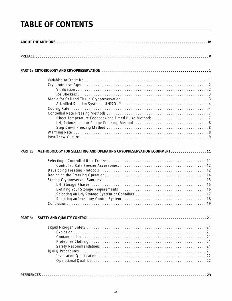
Kelvin G. M. Brockbank, PhD, is theSenior Vice President of Scientific,Clinical, and Regulatory Affairsat Organ Recovery Systems, Inc.,in Charleston, South Carolina.Organ Recovery Systems is adevelopment stage companyfocused on bringing improvedlow temperature devices and
techniques to medicine, particularly in the fieldsof cell, tissue, organ, and blood preservation.Dr. Brockbank has more than 20 years of projectmanagement experience in tissue engineering andmedical device research and development. His workhas been supported by competitive grants from theNational Institutes of Health (NIH), National Instituteof Standards and Technology (NIST) AdvancedTechnology Program, cancer foundations, theDepartment of Defense, and venture capital funds.Dr. Brockbank has served as Vice President ofResearch and Development for Baxter HealthCareCorporation and Director of Research andDevelopment for CryoLife, Inc. He is the inventor/co-inventor of clinical cryopreservation methodscurrently employed for viable meniscal allografts,allogeneic heart valves, ligaments, and vasculargrafts. Dr. Brockbank has approximately 250publications and patents. He received his PhD inExperimental Pathology from the Medical Universityof South Carolina, Charleston, South Carolina.E-mail: [email protected]
James C. Covault was formerlya Senior Product Manager atThermo Electron Corporation inMarietta, Ohio. This facility,founded in 1950, is knownworldwide as a leading manu-facturing site of controlledenvironment lab equipment. Jimbrought more than 20 years of
experience with cryopreservation and relatedcontrolled environment equipment. He held variouspositions in management for CryoMed, which waspurchased in 1991. Jim received his Bachelor’sdegree in Business Administration from WayneState University, Detroit, Michigan, and his Master’sdegree and a Certificate in Microcomputersfrom Marietta College, Marietta, Ohio.
ABOUT THE AUTHORS
Michael J. Taylor, PhD, is the VicePresident of Research andDevelopment at Organ RecoverySystems, Inc., and an AdjunctProfessor of Surgery at theMCP-Hahnemann University inPittsburgh, Pennsylvania. Beforejoining Organ Recovery Systemsin 1998, Dr. Taylor served as the
Director of the Cryobiology and HypothermicMedicine Program at Allegheny University, and until1992 he was the Senior Scientist with the MedicalResearch Council at Cambridge University, UnitedKingdom. Dr. Taylor has more than 100 publicationsand patents in the field of low temperature biologyand medicine and is a member of the editorialboards of the major journals—Cryobiology andCryoLetters—in the field. He has also servedmultiple terms on the Board of Governors for theInternational Society for Cryobiology and has heldthe offices of Secretary and Treasurer.E-mail: [email protected]
v
The Cryopreservation Manual, A Guide toCryopreservation Techniques is a practicalhandbook for scientists who are responsible foran organization’s cryopreservation program.This guide presents the following:
• Overview of the cryobiology of cell and tissue preservation
• Comprehensive methodology for selecting andoperating cryopreservation equipment
Controlled rate freezing methods aswell as controlled rate freezingequipment selection criteria areaddressed. Programming and running acryopreservation protocol is explained,detailed graphs are included, and datastorage is outlined. Various styles ofavailable storage and inventory systemsare reviewed. A checklist of questionshelps you narrow down the choices thatwill fit your research requirements.
• Guidance regarding installation and operationalqualifications, and safety required in a GoodManufacturing Practices (GMP) laboratory
You will be better prepared to do the following afterreading this guide:
• Differentiate various types of controlled ratefreezing methods and their purposes
PREFACE
• Develop a protocol for freezing a selectedsample in which the potential for cell viability is maximized
• Understand and identify sample phase changes
• Select an appropriate storage system andaccessories to meet your required protocol, facilityrestraints, and budget
• Develop an installation and operationalqualification (IQ/OQ) procedure required for aGMP laboratory
Organizations that may employ cryopreservationtechniques and find the information in this guideuseful include the following:
• Hospital Research Laboratories
• University Research Laboratories
• Government Research Laboratories
• Industrial Research Laboratories
• Pharmaceutical Research Laboratories
• Veterinary Research Laboratories
• Agricultural Research Laboratories
• Tissue Banks
• Commercial Vaccine Operations
• Blood Banks
• Biotechnology Firms

1
Cryobiology is the study of the effects of extremelylow temperatures on biological systems, such ascells or organisms. Cryopreservation—an appliedaspect of cryobiology—has resulted in methods thatpermit low temperature maintenance of a diversityof cells. The objective of cryopreservation is tominimize damage to biological materials, includingtissues, mammalian cells, bacteria, fungi, plant cells,and viruses, during low temperature freezing andstorage. Cryopreservation provides a continuoussource of tissues and genetically stable living cellsfor a variety of purposes, including research andbiomedical processes.
A basic principle of cryobiology is that the extent offreezing damage depends on the amount of freewater in the system and the ability of that water tocrystallize during freezing. Water is the majorcomponent of all living cells and must be presentfor chemical reactions to occur within a cell.During freezing, most of the water changes to ice,and cellular metabolism ceases. By followingpublished procedures, you can successfully freezemany types of isolated cells and small cellaggregates. However, obtaining reproducible resultsfor more complex tissues, such as heart valves orengineered tissue constructs, or more sensitive celltypes, requires an understanding of the majorvariables involved in tissue cryopreservation.
VARIABLES TO OPTIMIZE
Ice formation initiates in the extracellularenvironment, resulting in increased saltconcentrations as water is removed to form ice.This ice formation results in an osmotic imbalance.Water then leaves the cells by osmosis, and cellulardehydration results. Cryosubstituted cryopreservedtissues demonstrate dehydrated cells sandwichedbetween extracellular ice domains. Excessivedehydration can be detrimental to cell recovery.
Potentially detrimental effects of dehydration and icecan be minimized by doing the following:
• Controlling the cooling rate by using an appropriate controlled rate freezer
• Using cryoprotective agents in appropriatevehicle solutions
• Maintaining appropriate storage temperatures
• Controlling the rewarming rate
All of these events interact to influence the outcomeof cryopreservation. Highest survival is attained byoptimizing the series of interrelated variables listedin Table 1.
Table 1.Key Cryobiological Variables for Optimization
Type of preservation medium
Cryoprotective agents• Choice• Concentration
Pre-freeze equilibration schedule
Initiated (i.e., “seeding”) or spontaneous freezing
Cooling rate
Termination temperature of controlled rate cooling
Storage temperature
Warming rate
CPA dilution schedule• Temperature
- Serial, direct, or osmotic buffer step dilution- Presence of serum
Post-thaw culture
These interrelated variables are addressed in thefollowing sections: Cryoprotective Agents, Mediafor Cell and Tissue Cryopreservation, Cooling Rate,Warming Rate, and Post-Thaw Culture.
PART 1: CRYOBIOLOGY AND CRYOPRESERVATION
The variables known to have the most significantinfluence on cell survival are shown in bold type. Ofthese, cooling rate is especially important.
*Derived from vitri, the Greek word for glass
2
CRYOPROTECTIVE AGENTS
Cryoprotective agents (CPAs), or cryoprotectants,and their mechanisms of action have been thesubject of many excellent reviews (Karow 1981,Mazur 1984, Brockbank 1995). Glycerol and DMSOare the most commonly employed cryoprotectiveagents. Fetal bovine serum (FBS) is often used inmammalian cryopreservation solutions, but itis not a cryoprotective agent. Salts, suchas magnesium chloride, have been reportedto be cryoprotective agents (Karow and Carrier1969). Dextrans, glycols, starches, sugars,and polyvinylpyrrolidone provide considerablecryoprotection in a variety of biologic systems(Mazur 1981). Cryoprotectants protect slowly frozencells by one or more of the following mechanisms:
• Suppressing high salt concentrations
• Reducing cell shrinkage at a given temperature
• Reducing the fraction of the solution frozen at agiven temperature
• Minimizing intracellular ice formation
Combinations of cryoprotectants may result inadditive or synergistic enhancement of cell survival(Brockbank and Smith 1993, Brockbank 1992).Comparison of chemicals with cryoprotectantproperties reveals no common structural features.These chemicals are usually divided into thefollowing two classes:
• Intracellular cryoprotectants with low molecularweights that permeate cells. Intracellularcryoprotectants, such as glycerol and dimethylsulfoxide at concentrations from 0.5 to 3 molar,are effective in minimizing cell damage in manyslowly frozen biological systems.
• Extracellular cryoprotectants with relatively highmolecular weights—greater than or equal tosucrose (342 daltons)—that do not penetrate cells.Extracellular cryoprotective agents, such aspolyvinylpyrrolidone and hydroxyethyl starch, aremore effective at protecting biological systemscooled at rapid rates. These agents are oftenlarge macromolecules that affect the solution’sproperties to a greater extent than would be
expected from their osmotic pressure. Some ofthese non-permeating cryoprotective agents havedirect protective effects on the cell membrane.However, the primary mechanism of actionappears to be the induction of vitrification(extracellular glass formation).
Ice formation can be eliminated entirely, bothwithin the cells and the extracellular matrix,when cryoprotectants are used in extremely highconcentrations (i.e., at least 50% volume/volume)(Fahy 1988).
VITRIFICATION
Preventing freezing requires that the water in atissue remains liquid during cooling. However, ascooling proceeds, the molecular motions in the liquidpermeating the tissue decrease. Eventually, an“arrested liquid” state known as a glass is achieved.Vitrification* is this conversion of a liquid into aglass. Glass is a liquid that is too cold to flow.A vitrified liquid is essentially a liquid in molecularstasis. Vitrification is solidification due to increasedviscosity rather than to crystallization. The pointbelow which the vitreous material can be consideredsolid is somewhat arbitrary and depends on the timescale of interest.
Typically, a vitrified material is considered solid whenthe viscosity reaches ~1015 poise. The temperatureat which the material can be considered glass isknown as the glass transition temperature. Glasstransition is usually associated with a suddenchange in density, which may result in highmechanical stresses and material fractures.These can be avoided if the biomaterial is vitrifiedbut stored at, or just below, the glass transitiontemperature. Theoretically, vitrification does nothave any of the biologically damaging effectsassociated with freezing.
Vitrification is commonly used to preserve gametes.Vitrification techniques were successfully applied toa variety of complex biological materials—kidney,liver, and heart organ slices, and tissues (i.e., bloodvessels, cartilage, skin, cornea). Ice formation waseffectively prevented and cell viability was retained.
3
ICE BLOCKERS
A new area of research in cell and tissuepreservation is control of ice formation. Nature hasproduced several families of proteins that permitcertain animals and plants to survive in extremelycold climates. These proteins are known collectivelyas antifreeze proteins. It is believed that fish-derivedantifreeze proteins act by preferential adsorption tothe prism face or to internal planes of ice in such amanner that ice crystal growth perpendicular to theprism face is inhibited. Synthetic ice blockers thatmodify both ice crystal growth rates and form arebeing developed at Organ Recovery Systems, Inc.Synthetic ice blockers may be combinedwith naturally occurring antifreeze proteins andconventional cryoprotectants to develop improvedpreservation methods in which both the cells andthe extracellular matrices are preserved.
MEDIA FOR CELL AND TISSUECRYOPRESERVATION
Almost without exception, successful cryo-preservation methods begin with a pre-freeze, orpre-vitrification, phase in which the cells aretransferred from a physiological environment toa cryoprotective solution. The latter comprises asuitable buffer medium that contains specialCPAs essential to minimize freeze-induced injury.Invariably, this pre-freeze phase involves an initialcooling phase, often referred to as the hypothermicphase. This hypothermic phase serves two purposes:
• Slows metabolism and minimizes ischemic andhypoxic changes
• Reduces the chemical toxicity of the CPAs
Biological materials may be packaged directly in thepre-cooled cryoprotective solution—0C to 4C (32F to39.2F)—and then moved to a similarly pre-cooledcryopreservation chamber. Or, a cryopreservationdevice, such as a controlled rate freezer, may beused to cool the materials from physiological orroom temperature to 0C to 4C (32F to 39.2F).
Optimum control of the cells’ environment duringcryopreservation demands that you consider thechemical composition of the buffer medium used asa vehicle for the CPAs as well as the temperature towhich the cells are exposed. Although conventional
culture media are commonly used for this purpose,it should not be assumed that a tissue culturemedium is an ideal or optimum vehicle solution forexposing cells to low temperatures.
A variety of factors are known to influence cellsurvival during cryopreservation, but the role of thevehicle solution for the CPAs is often overlooked.It is generally assumed that conventional culturemedia used to nurture cells at physiologicaltemperatures will also provide a suitable medium forexposure at low temperatures. However, it is nowwell established in tissue and organ preservationthat the ionic and hydraulic balance in cellsduring hypothermia can be better controlled byusing solutions designed to physically restricttemperature-induced imbalances (Taylor and Hunt1985; Taylor, Elrifai, and Bailes 1996).
Preservation by cooling is achieved by striking abalance between the beneficial and harmful effectsof reducing temperature. The most beneficial effectof cooling is the slowing of chemical reactions and,therefore, the decreased demand for oxygen andother substrates and the conservation of chemicalenergy. Rapid cooling may be harmful due to thermalshock. It has been a common practice in tissuebanking to use tissue culture media as the basesolution for preservation media. However, there aregood reasons why tissue culture media, which aredesigned to maintain cellular function at normalphysiological temperatures, are inappropriate foroptimum preservation at reduced temperatures.
Maintaining the ionic and hydraulic balance withintissues during hypothermia can be better controlledin media designed to physically restrict thesetemperature-induced imbalances. This principle isembodied in the design of organ preservationsolutions used for short-term hypothermic storageof kidneys, livers, and hearts without freezing (Taylor2001) and can be applied equally to the choice ofvehicle solution for adding and removing CPAs in acryopreservation protocol.
Media designed for hypothermic preservation arebased on the premise that reducing temperature tonear the ice point (0C, or 32F) precludes the need tosupport metabolism to any significant extent.Under these conditions the correct distribution ofwater and ions between the intracellular andextracellular compartments can be maintainedby physical rather than metabolic means.This is possible because the metabolically-driven
4
membrane pumps are inactivated at suchhypothermic temperatures, and, in the absence ofmetabolism, the driving forces for transmembraneion and water fluxes can be prevented or restrictedby manipulating the extracellular environment.Such hypothermic preservation solutions are oftenreferred to as intracellular-type solutions becausethey resemble intracellular fluid in some respects.Principal design elements of the intracellular-typesolutions have been to do the following:
• Adjust the ionic balance (notably of themonovalent cations)
• Raise the osmolality by including an impermeantsolute to balance the intracellular osmoticpressure responsible for water uptake
A UNIFIED SOLUTION SYSTEM—UNISOL™
Organ Recovery Systems, Inc. developed theUNISOL concept, which is a unified solution systemfor both hypothermic storage and cryopreservationbased in part on the principle design elementsoutlined above. The base solution is used as avehicle solution for a range of additives to derive asystem of solutions that are optimized fordifferent applications. A CPA vehicle version ofUNISOL has been developed and was recentlyshown to be superior to EuroCollins solution duringthe cryopreservation of a variety of cells (Taylor,Campbell, Rutledge, and Brockbank 2001).
➢ As a practical note, it is recommended thatthe CPA vehicle solution be prepared as aconcentrated solution (typically 3x) to allowincorporation of the cryoprotective agents on aweight percentage basis before diluting tosingle strength. This preferred method avoidsdilution of the salts and buffers that otherwiseoccurs when CPAs are added to a singlestrength vehicle solution.
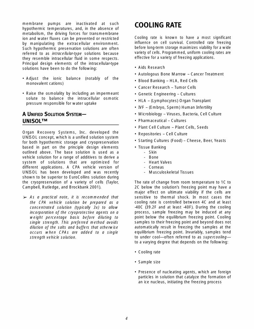
COOLING RATE
Cooling rate is known to have a most significantinfluence on cell survival. Controlled rate freezingbefore long-term storage maximizes viability for a widevariety of cells. Programmed, uniform cooling rates areeffective for a variety of freezing applications.
• Aids Research
• Autologous Bone Marrow – Cancer Treatment
• Blood Banking – HLA, Red Cells
• Cancer Research – Tumor Cells
• Genetic Engineering – Cultures
• HLA – (Lymphocytes) Organ Transplant
• IVF – (Embryo, Sperm) Human Infertility
• Microbiology – Viruses, Bacteria, Cell Culture
• Pharmaceutical – Cultures
• Plant Cell Culture – Plant Cells, Seeds
• Repositories – Cell Culture
• Starting Cultures (Food) – Cheese, Beer, Yeasts
• Tissue Banking- Skin- Bone- Heart Valves- Corneas- Musculoskeletal Tissues
The rate of change from room temperature to 1C to2C below the solution’s freezing point may have amajor effect on ultimate viability if the cells aresensitive to thermal shock. In most cases thecooling rate is controlled between 4C and at least-40C (39.2F and at least -40F). During the coolingprocess, sample freezing may be induced at anypoint below the equilibrium freezing point. Coolingsamples to their freezing point and beyond does notautomatically result in freezing the samples at theequilibrium freezing point. Invariably, samples tendto under cool—often referred to as supercooling—to a varying degree that depends on the following:
• Cooling rate
• Sample size
• Presence of nucleating agents, which are foreignparticles in solution that catalyze the formation ofan ice nucleus, initiating the freezing process
5
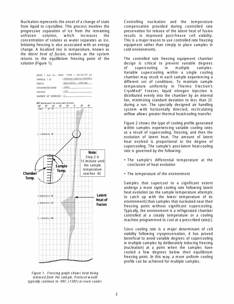
Nucleation represents the onset of a change of statefrom liquid to crystalline. This process involves theprogressive separation of ice from the remainingunfrozen solution, which increases theconcentration of solutes as water separates as ice.Initiating freezing is also associated with an energychange. A localized rise in temperature, known asthe latent heat of fusion, evolves as the systemreturns to the equilibrium freezing point of thesolution (Figure 1).
Controlling nucleation and the temperaturecompensation provided during controlled ratepreservation for release of the latent heat of fusionresults in improved post-freeze cell viability.This is a major reason to use controlled rate freezingequipment rather than simply to place samples incold environments.
The controlled rate freezing equipment chamberdesign is critical to prevent variable degreesof supercooling in multiple samples.Variable supercooling within a single coolingchamber may result in each sample experiencing adifferent set of conditions. To maintain sampletemperature uniformity in Thermo Electron’sCryoMed® Freezer, liquid nitrogen injection isdistributed evenly into the chamber by an internalfan, minimizing standard deviation to less than 2Cduring a run. The specially designed air handlingsystem with horizontally directed, recirculatingairflow allows greater thermal heat/cooling transfer.
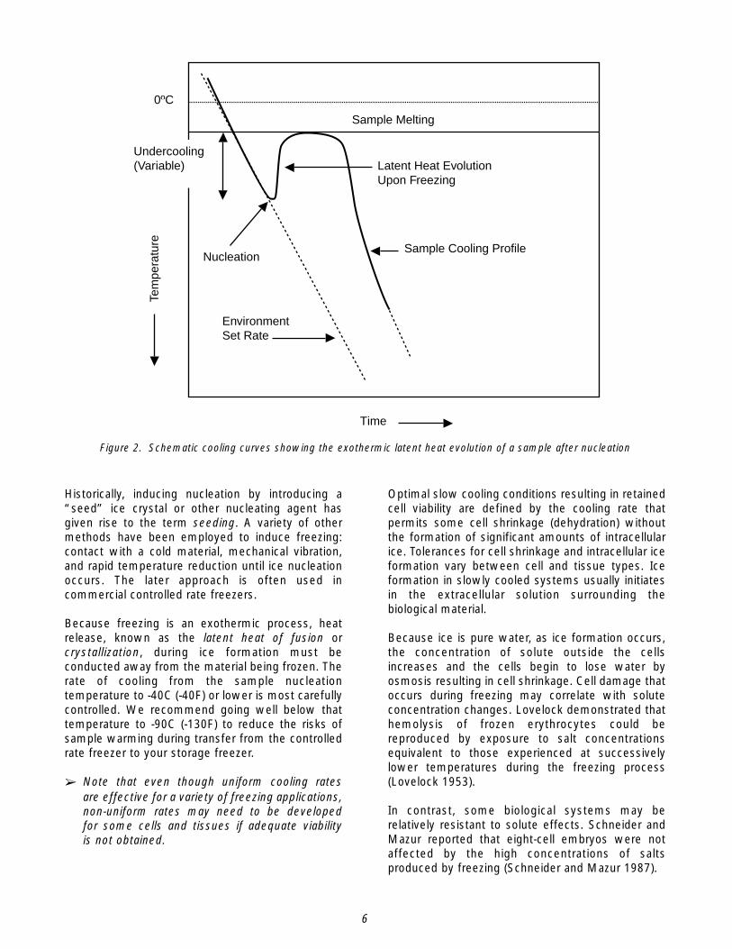
Figure 2 shows the type of cooling profile generatedwithin samples experiencing variable cooling ratesas a result of supercooling, freezing, and then theevolution of latent heat. The amount of latentheat evolved is proportional to the degree ofsupercooling. The sample’s post-latent heat-coolingrate is governed by the following:
• The sample’s differential temperature at theconclusion of heat evolution
• The temperature of the environment
Samples that supercool to a significant extentundergo a more rapid cooling rate following latentheat evolution (as the sample temperature attemptsto catch up with the lower temperature of itsenvironment) than samples that nucleated near theirfreezing point without significant supercooling.Typically, the environment is a refrigerated chambercontrolled at a steady temperature or a coolingmachine programmed to cool at a prescribed rate(s).
Since cooling rate is a major determinant of cellviability following cryopreservation, it has provedbeneficial to avoid variable degrees of supercoolingin multiple samples by deliberately inducing freezing(nucleation) at a point when the samples havecooled a few degrees below their equilibriumfreezing point. In this way, a more uniform coolingprofile can be achieved for multiple samples.
Figure 1. Freezing graph shows heat being released from the sample. Protocol would
typically continue to -90C (-130F) or even cooler.
Latent Heat ofFusion
ChamberTemp.
SampleTemp.
Note:Step 2 is
1C/minute untilthe sampletemperaturereaches -4C
6
Historically, inducing nucleation by introducing a“seed” ice crystal or other nucleating agent hasgiven rise to the term seeding. A variety of othermethods have been employed to induce freezing:contact with a cold material, mechanical vibration,and rapid temperature reduction until ice nucleationoccurs. The later approach is often used incommercial controlled rate freezers.
Because freezing is an exothermic process, heatrelease, known as the latent heat of fusion orcrystallization, during ice formation must beconducted away from the material being frozen. Therate of cooling from the sample nucleationtemperature to -40C (-40F) or lower is most carefullycontrolled. We recommend going well below thattemperature to -90C (-130F) to reduce the risks ofsample warming during transfer from the controlledrate freezer to your storage freezer.
➢ Note that even though uniform cooling ratesare effective for a variety of freezing applications,non-uniform rates may need to be developedfor some cells and tissues if adequate viabilityis not obtained.
Optimal slow cooling conditions resulting in retainedcell viability are defined by the cooling rate thatpermits some cell shrinkage (dehydration) withoutthe formation of significant amounts of intracellularice. Tolerances for cell shrinkage and intracellular iceformation vary between cell and tissue types. Iceformation in slowly cooled systems usually initiatesin the extracellular solution surrounding thebiological material.
Because ice is pure water, as ice formation occurs,the concentration of solute outside the cellsincreases and the cells begin to lose water byosmosis resulting in cell shrinkage. Cell damage thatoccurs during freezing may correlate with soluteconcentration changes. Lovelock demonstrated thathemolysis of frozen erythrocytes could bereproduced by exposure to salt concentrationsequivalent to those experienced at successivelylower temperatures during the freezing process(Lovelock 1953).
In contrast, some biological systems may berelatively resistant to solute effects. Schneider andMazur reported that eight-cell embryos were notaffected by the high concentrations of saltsproduced by freezing (Schneider and Mazur 1987).
Sample Melting
Latent Heat EvolutionUpon Freezing
Nucleation
EnvironmentSet Rate
Sample Cooling Profile
Time
0ºC
Tem
pera
ture
Undercooling(Variable)
Figure 2. Schematic cooling curves showing the exothermic latent heat evolution of a sample after nucleation
7
They suggested that cellular survival may bedetermined by the fraction of extracellular solutethat remains unfrozen, and that cellular distortionmay cause significant damage to cells. In contrast,rapid cooling is generally regarded as harmful to cellviability with certain exceptions, such as red bloodcells. Rapid cooling may conveniently be defined asa freezing rate in which little or no cell shrinkageoccurs from osmotically driven dehydration.However, at rapid cooling rates the randomformation of ultra-structural, intracellular ice occurs.Furthermore, under suboptimal rewarmingconditions this intracellular ice may grow anddestroy the cells.
Studies on the survival of various mammalian celltypes frozen at a variety of rates suggest that theoptimal cooling rate usually lies between 0.3C and10C per minute. Each cell type has a freezing“window” in which the cooling rate provides optimalcell survival. This “window” is narrow at relativelyhigh sub-zero temperatures and becomesincreasingly wider as the temperature decreases.Therefore, deviations from establishedcryopreservation protocols close to zero may be more critical for cell survival than deviations atlower temperatures.
CONTROLLED RATEFREEZING METHODS
A major reason to use controlled rate freezingequipment rather than simply to place samples incold environments is that the temperaturecompensation provided during controlled ratepreservation for release of the latent heat resultsin improved post-cryopreservation cell viability.This temperature compensation is provided bya programmed decrease in chamber temperaturethat both initiates nucleation and subsequentlycompensates for the release of the latent heatof fusion. The major variables involved are rateof chamber temperature decrease, hold temperatureand duration, the rate of temperature increase, andthe temperature at which chamber cooling is re-initiated.
The most popular methods of controlled ratefreezing on the market today are as follows:
• Liquid Nitrogen (LN2) Methods- Direct temperature feedback- Timed pulse- Liquid nitrogen submersion, or plunge freezing
• Step Down Method
The use of liquid nitrogen, either by itself or as asource of nitrogen gas, is based on the followingunique combination of features:
• Chemically inert
• Relatively low cost
• Non-toxic
• Non-flammable
• Readily available
DIRECT TEMPERATURE FEEDBACK AND
TIMED PULSE METHODS
The Direct Temperature Feedback and the TimedPulse Methods control the chamber temperature,not the sample temperature, though most controlledrate freezers may advance a program step based onthe sample temperature. In other words, when thecriteria (sample temperatures) are met, the programproceeds to the next step and new criteria.
With the Direct Temperature Feedback method, theamount of liquid nitrogen injected into the chamberis determined by Type T thermocouples controllingthe chamber and monitoring the sampletemperature while comparing actual to programchamber temperatures. The controller automaticallyadjusts for low pressure liquid nitrogen supply,faster freezing rates, or defective solenoid valves byincreasing valve cycles through two independentvalves or by turning on a heater to compensate forexcessive coolant.
Some Direct Temperature Feedback systems usedual solenoid valves. These valves provide dualinjection of liquid nitrogen, permitting faster freezingrates and providing more precise temperaturecontrol. Although solenoids wear over time, dualvalves provide a back-up for coolant injection. If onevalve fails, the failed valve should not produceaberrant results with solenoid wear. The secondvalve would serve as a back-up.
8
With the Timed Pulse method, which is oftenengineered with a microprocessor control system,a solenoid valve(s) meters a timed pulse ofliquid nitrogen into the chamber. The amount ofliquid nitrogen injected is determined by valvesize, tank pressure, valve core wear resistance,and number of solenoid openings. The numberof solenoid openings is determined by thetemperature-freezing rate programmed.
The Timed Pulse method requires use of a smallDewar flask and a liquid nitrogen Cryo pump system.The pump or heater “boils off” liquid nitrogen,providing consistent pressure and ensuring ameasured injection of coolant. This measuredamount is used in the calculation that determinesthe cycle rate of the solenoid valve providing theprogrammed freezing rate. The controller may notautomatically compensate for program deviations.
If a Timed Pulse unit has only one valve andthe operator requires faster cooling rates, themanufacturer may provide a larger orifice valve.However, this may result in temperature controlproblems at slower cooling rates. With a TimedPulse unit, different cooling curves over time whileusing the same program may become evident.Although the differences often look like a calibrationproblem, they may really be the solenoids showing wear.
LN2 SUBMERSION, OR PLUNGE
FREEZING, METHOD
The third method of controlled rate freezing is LiquidNitrogen Submersion, or Plunge Freezing. Samples areloaded into a heat block, and that block issubmerged into LN2. Then, the heater bucks, ortempers, the LN2 to obtain a controlled freezing rate.This method has been used successfully for smallnumbers of low volume straws and vials.
STEP DOWN FREEZING METHOD
Step Down Freezing is an often practiced but lessautomated freezing method. The samples are placedin a refrigerator overnight, transferred to a -70C(-94F) freezer for a period of time, and moved tonitrogen vapor. In some cases, the samples areplunged into liquid nitrogen for permanent storage.This freezing process is time consuming, difficultto repeat and document, and does not providethe controlled cooling rates and ice nucleationassociated with a true controlled rate freezer.
WARMING RATE
The rate of rewarming cryopreserved samples canalso impact the outcome (i.e., cell viability), but ingeneral this is less critical than the controlled rate ofcooling. However, cryobiological variables interact todetermine outcome, and the optimum warming rateusually depends on prior cooling conditions.
In most cryopreservation procedures the coolingrate was optimized for rapid rewarming, and in thesecircumstances slow warming reduces survival.However, successful preservation of mammalianembryos was achieved only after the discoverythat slow warming was essential for survival(Whittingham, Leibo, and Mazur 1972). It seemslikely that this was due to the cells becoming heavilyloaded with solutes, including the cryoprotectant,during slow cooling. This combined with the cells’low water permeability caused osmotic lysis uponthawing. Slow warming allowed sufficient timefor cell rehydration and gradual loss ofaccumulated solutes. Similarly, it is known thatred blood cells, which have traditionally beencryopreserved using rapid cooling and warming, canbe recovered successfully after slow cooling in thepresence of glycerol if they are also thawed slowly(Miller and Mazur 1976).
The prevalence of references to rapid warming ratesin cryopreservation publications is mostly due to thecommon decision to study the cooling rate first,keeping the warming rate constant by sampleimmersion in a warm water bath. Consequently,subsequent experiments to study warming rate,using the single cooling rate found to be optimalin the initial studies, will be bound to show rapidwarming to be optimal! It is only by studyingan extensive matrix of cooling and warming ratesthat the interaction of these two variables can beclearly seen.
Reasons for the interactions are complex. Cellspreserved by cooling at a rate optimized for use withsubsequent rapid thawing contain small intracellularice crystals. If such cryopreserved samples arewarmed slowly, the small ice crystal nuclei tend togrow by recrystallization, causing cell damage(Farrant, et al. 1977; Farrant, Lee, and Walter 1977b).
The cells can survive rapid thawing because theyaccumulated relatively little solute during rapidcooling, and recrystallization has little opportunity tooccur during rapid warming. Cooling rate andwarming rate cannot be optimized independently.

9
POST-THAW CULTURE
After thawing, the final stage of anycryopreservation procedure is to return the cells totheir normal environment—isotonic physiologicalsolutions or body fluids that lack cryoprotectiveagent. This imposes similar osmotic problems to those induced by thawing because an osmoticgradient is again established across the plasma membrane.
Balancing solute loss and water influx is essential if cell swelling is to be kept within tolerable limits. In practice, this involves either of the following methods:
• Diluting the cryoprotectant incrementally, atappropriate time intervals, to maintain cell volumebelow the threshold for damage
• Diluting the cryoprotectant in the presence of a non-permeating solute (e.g., sucrose) that prevents cell swelling as solutes diffuseout of the cells

11
This section provides guidance about selecting acontrolled rate freezer and accessories, developingfreezing protocols, and choosing a storage andinventory control system (e.g., racks, canisters).
SELECTING A CONTROLLEDRATE FREEZER
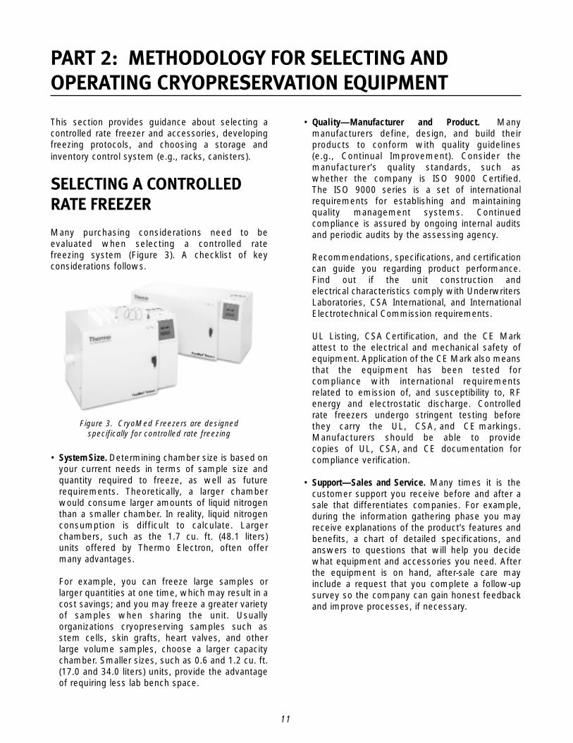
Many purchasing considerations need to beevaluated when selecting a controlled ratefreezing system (Figure 3). A checklist of keyconsiderations follows.
• System Size. Determining chamber size is based onyour current needs in terms of sample size andquantity required to freeze, as well as futurerequirements. Theoretically, a larger chamberwould consume larger amounts of liquid nitrogenthan a smaller chamber. In reality, liquid nitrogenconsumption is difficult to calculate. Largerchambers, such as the 1.7 cu. ft. (48.1 liters) units offered by Thermo Electron, often offermany advantages.
For example, you can freeze large samples orlarger quantities at one time, which may result in acost savings; and you may freeze a greater varietyof samples when sharing the unit. Usuallyorganizations cryopreserving samples such asstem cells, skin grafts, heart valves, and otherlarge volume samples, choose a larger capacitychamber. Smaller sizes, such as 0.6 and 1.2 cu. ft.(17.0 and 34.0 liters) units, provide the advantageof requiring less lab bench space.
• Quality—Manufacturer and Product. Manymanufacturers define, design, and build theirproducts to conform with quality guidelines(e.g., Continual Improvement). Consider themanufacturer’s quality standards, such aswhether the company is ISO 9000 Certified.The ISO 9000 series is a set of internationalrequirements for establishing and maintainingquality management systems. Continuedcompliance is assured by ongoing internal auditsand periodic audits by the assessing agency.
Recommendations, specifications, and certificationcan guide you regarding product performance.Find out if the unit construction andelectrical characteristics comply with UnderwritersLaboratories, CSA International, and InternationalElectrotechnical Commission requirements.
UL Listing, CSA Certification, and the CE Markattest to the electrical and mechanical safety ofequipment. Application of the CE Mark also meansthat the equipment has been tested forcompliance with international requirementsrelated to emission of, and susceptibility to, RFenergy and electrostatic discharge. Controlled rate freezers undergo stringent testing beforethey carry the UL, CSA, and CE markings.Manufacturers should be able to providecopies of UL, CSA, and CE documentation for compliance verification.
• Support—Sales and Service. Many times it is thecustomer support you receive before and after asale that differentiates companies. For example,during the information gathering phase you mayreceive explanations of the product’s features andbenefits, a chart of detailed specifications, andanswers to questions that will help you decidewhat equipment and accessories you need. Afterthe equipment is on hand, after-sale care mayinclude a request that you complete a follow-upsurvey so the company can gain honest feedbackand improve processes, if necessary.
Figure 3. CryoMed Freezers are designed specifically for controlled rate freezing
PART 2: METHODOLOGY FOR SELECTING ANDOPERATING CRYOPRESERVATION EQUIPMENT
12
Many manufacturers have distributors for theirproducts, others have a direct, factory-trainedsales force. Multiple modes of distribution aretypical. Find out if the sales personnel are readilyavailable to answer your questions and whetherthey can help set up your equipment when it arrives. Also verify that the manufacturer is ableto ship the controlled rate freezer(s) to meet your timeframe.
Everyone hopes that a product won’t requireservice. However, periodic maintenance or finetuning will keep your equipment in peakoperating condition. Therefore, ask the salesrepresentative or distributor about after-saleservice and determine the following:
- Was the unit designed for easy access tocomponents?
- Whom do you call for assistance?
- What are the hours of operation?
- Are technicians available by phone to help youtroubleshoot problems, if necessary?
- What are the warranty conditions?
- Are extended warranties and maintenanceagreements available?
• Price. Everyone wants the best deal possiblewhen making a purchase. Is the pricecompetitive? If it is not, try to identify thereason(s). Are there additional features on one unitthat are optional on another? Is the product moredependable or expected to have a longer life?Ensure that you are comparing “apples to apples.”
CONTROLLED RATE FREEZER ACCESSORIES
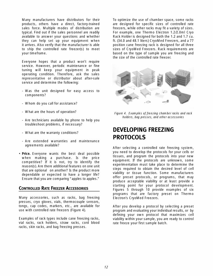
Many accessories, such as racks, bag freezingpresses, cryo gloves, vials, thermocouple sensors,tongs, cap codes, markers, etc., are available foruse with controlled rate freezers (Figure 4).
Examples of rack types include cane freezing racks,vial racks, rack holders, straw racks, cord bloodracks, skin racks, and bag freezing presses.
To optimize the use of chamber space, some racksare designed for specific sizes of controlled ratefreezers, while other racks may fit a variety of sizes.For example, one Thermo Electron 1.2/2.0ml CryoRack Holder is designed for both the 1.2 and 1.7 cu.ft. (34.0 and 48.1 liters) CryoMed Freezers, and a 77position cane freezing rack is designed for all threesizes of CryoMed Freezers. Rack requirements arebased on the type of sample you are freezing andthe size of the controlled rate freezer.
DEVELOPING FREEZINGPROTOCOLS
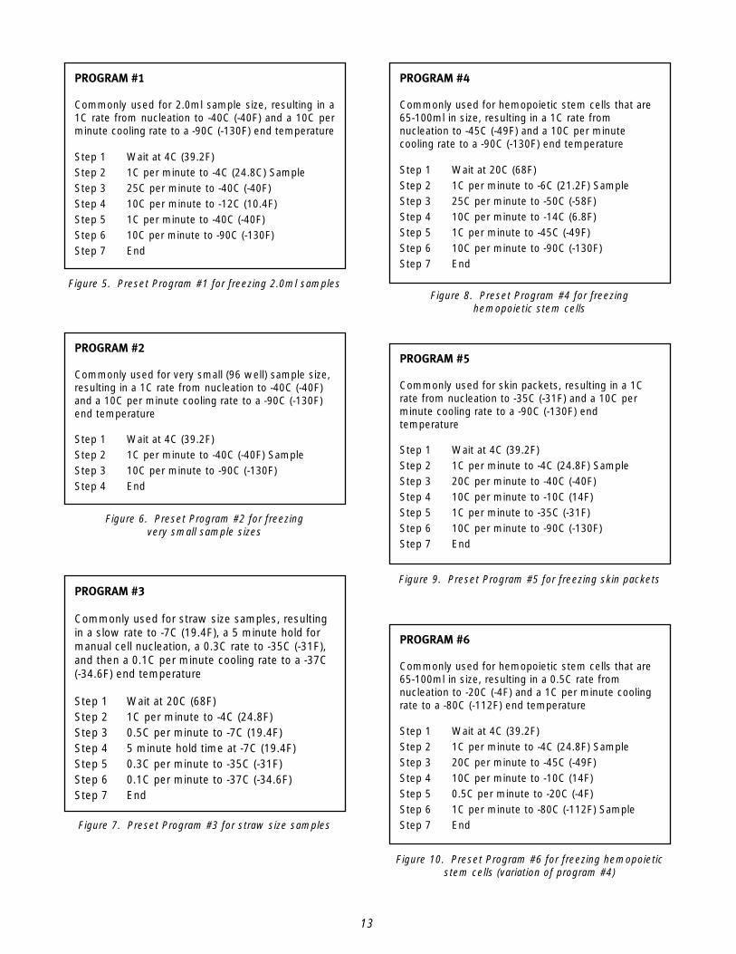
After selecting a controlled rate freezing system,you need to develop the protocols for your cells ortissues, and program the protocols into your newequipment. If the protocols are unknown, someexperimentation must take place to determine thesteps required to obtain the desired level of cellviability or tissue function. Some manufacturersoffer preset protocols, or programs, that mayproduce acceptable viability or at least provide astarting point for your protocol development. Figures 5 through 10 provide examples of sixprograms that are factory preset on ThermoElectron’s CryoMed Freezers.
After you develop a protocol by selecting a presetprogram and evaluating your individual results, or bydefining your own protocol that maximizes cellviability within your sample, you are ready to controlrate freeze your first sample batch.
Figure 4. Examples of freezing chamber racks and rack holders, bag presses, and other accessories
13
PROGRAM #3
Commonly used for straw size samples, resultingin a slow rate to -7C (19.4F), a 5 minute hold formanual cell nucleation, a 0.3C rate to -35C (-31F),and then a 0.1C per minute cooling rate to a -37C(-34.6F) end temperature
Step 1 Wait at 20C (68F)Step 2 1C per minute to -4C (24.8F)Step 3 0.5C per minute to -7C (19.4F)Step 4 5 minute hold time at -7C (19.4F)Step 5 0.3C per minute to -35C (-31F)Step 6 0.1C per minute to -37C (-34.6F)Step 7 End
Figure 7. Preset Program #3 for straw size samples
PROGRAM #1
Commonly used for 2.0ml sample size, resulting in a1C rate from nucleation to -40C (-40F) and a 10C perminute cooling rate to a -90C (-130F) end temperature
Step 1 Wait at 4C (39.2F)Step 2 1C per minute to -4C (24.8C) SampleStep 3 25C per minute to -40C (-40F)Step 4 10C per minute to -12C (10.4F)Step 5 1C per minute to -40C (-40F)Step 6 10C per minute to -90C (-130F)Step 7 End
Figure 5. Preset Program #1 for freezing 2.0ml samples
PROGRAM #2
Commonly used for very small (96 well) sample size,resulting in a 1C rate from nucleation to -40C (-40F)and a 10C per minute cooling rate to a -90C (-130F)end temperature
Step 1 Wait at 4C (39.2F)Step 2 1C per minute to -40C (-40F) SampleStep 3 10C per minute to -90C (-130F)Step 4 End
Figure 6. Preset Program #2 for freezing very small sample sizes
PROGRAM #4
Commonly used for hemopoietic stem cells that are65-100ml in size, resulting in a 1C rate fromnucleation to -45C (-49F) and a 10C per minutecooling rate to a -90C (-130F) end temperature
Step 1 Wait at 20C (68F)Step 2 1C per minute to -6C (21.2F) SampleStep 3 25C per minute to -50C (-58F)Step 4 10C per minute to -14C (6.8F)Step 5 1C per minute to -45C (-49F)Step 6 10C per minute to -90C (-130F)Step 7 End
Figure 8. Preset Program #4 for freezing hemopoietic stem cells
PROGRAM #5
Commonly used for skin packets, resulting in a 1Crate from nucleation to -35C (-31F) and a 10C perminute cooling rate to a -90C (-130F) endtemperature
Step 1 Wait at 4C (39.2F)Step 2 1C per minute to -4C (24.8F) SampleStep 3 20C per minute to -40C (-40F)Step 4 10C per minute to -10C (14F)Step 5 1C per minute to -35C (-31F)Step 6 10C per minute to -90C (-130F)Step 7 End
Figure 9. Preset Program #5 for freezing skin packets
PROGRAM #6
Commonly used for hemopoietic stem cells that are65-100ml in size, resulting in a 0.5C rate fromnucleation to -20C (-4F) and a 1C per minute coolingrate to a -80C (-112F) end temperature
Step 1 Wait at 4C (39.2F)Step 2 1C per minute to -4C (24.8F) SampleStep 3 20C per minute to -45C (-49F)Step 4 10C per minute to -10C (14F)Step 5 0.5C per minute to -20C (-4F)Step 6 1C per minute to -80C (-112F) SampleStep 7 End
Figure 10. Preset Program #6 for freezing hemopoieticstem cells (variation of program #4)

14
2. LIQUID PHASE COOLING. This is the phase duringwhich the liquid sample is cooled beforenucleation. A typical cooling rate is between0.2C per minute and 10C per minute.
3. SUPERCOOLING. This phase refers to thetemperature drop, just before the liquid-to-solidphase change, below the freezing point of thefreezing medium. Typically, it is 3C to 4C (37.5F to 39.2F) below the freezing point butmay be much lower if nucleation is allowed tooccur spontaneously.
4. PHASE CHANGE. The beginning of the liquid-to-solid phase change process is characterized by arapid increase in temperature from thesupercooled temperature to the freezingtemperature. The chamber temperature isdropped rapidly to minimize the sampletemperature rise during the phase change. The magnitude and duration of the dropdepend on the sample volume and geometry. This rapid cooling provides a heat sink for thelatent heat of fusion.
5. SOLID PHASE I FREEZING. The cooling rateselected for Solid Phase I Freezing isindependent of the liquid phase cooling rate.This rate is determined by the operator, asrequired, and is often the same as the liquidphase cooling rate of 1C per minute.
END SOLID PHASE I FREEZING. This is the finaltemperature achieved in the Solid Phase I Freezingcycle. It is usually set between -30C and -50C(-22F and -58F), as required by the operator.
The protocol freezing rate may be increased toshorten the duration of the freezing cycle afterSolid Phase I Freezing is completed. A commonlyused rate is 10C per minute to an End Solid Phase IIFreezing temperature of between -80C and -90C(-112F and -130F). This provides adequatetemperature security by preventing sample warmingabove the End Solid Phase I Freezing temperatureduring sample transfer from the controlled ratefreezer to permanent storage.
BEGINNING THE FREEZINGOPERATION
Preparing the Freezing Chamber. Liquid nitrogen onlytransfers at liquid nitrogen temperatures, -196C(-320F); therefore, it is a good practice to begincycling the chamber to cool it before initiatingthe freezing run. Pre-cool the freezer chamber to4C (39.2F), which is ice bath temperature, whilepreparing your samples for batch freeze. A differentinitial chamber temperature can be used if validatedfor your samples. The objective is to equilibrate thechamber and sample temperatures before beginningthe controlled rate freeze.
Preparing the Samples. After preparing samples inan ice bath at 4C (39.2F), transfer them tothe pre-cooled chamber. A different sampleaccumulation temperature can be used if validatedfor your samples.
Freezing the Samples. After the samples are preparedand placed in the freezing chamber, the samples andchamber must be allowed to cool to the 4C StartTemperature. When the sample temperaturereaches the start temperature or at least within 2Cof the Start Temperature, advance the program toactivate the automated steps for protocolcompletion. Preset programs stored in CryoMedFreezers begin with a Wait step. This step ensuresthat you maintain control of when the remainingsteps of the controlled rate freezing process begin(i.e., Run is pressed a second time to initiate theremaining steps). The major phases of acryopreservation program are as follows:
1. START TEMPERATURE. The start temperature isusually the same as the sample temperature,before the samples are loaded into the freezingchamber. Usually the samples are at roomtemperature—22C (71.6F)—or at ice bathtemperature—4C (39.2F). When temperaturesbelow room temperature are used, both thesamples and the chamber may warm up duringsample transfer to the controlled rate freezerchamber. The chamber and samples shouldreach the start temperature before theautomated portion of the program is initiated.
15
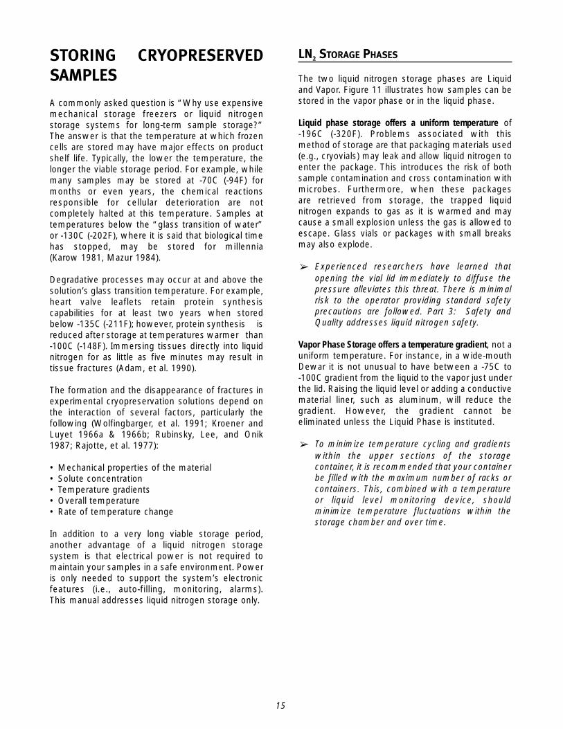
LN2 STORAGE PHASES
The two liquid nitrogen storage phases are Liquidand Vapor. Figure 11 illustrates how samples can bestored in the vapor phase or in the liquid phase.
Liquid phase storage offers a uniform temperature of-196C (-320F). Problems associated with thismethod of storage are that packaging materials used(e.g., cryovials) may leak and allow liquid nitrogen toenter the package. This introduces the risk of bothsample contamination and cross contamination withmicrobes. Furthermore, when these packages are retrieved from storage, the trapped liquidnitrogen expands to gas as it is warmed and maycause a small explosion unless the gas is allowed toescape. Glass vials or packages with small breaksmay also explode.
➢ Experienced researchers have learned thatopening the vial lid immediately to diffuse thepressure alleviates this threat. There is minimalrisk to the operator providing standard safetyprecautions are followed. Part 3: Safety andQuality addresses liquid nitrogen safety.
Vapor Phase Storage offers a temperature gradient, not auniform temperature. For instance, in a wide-mouthDewar it is not unusual to have between a -75C to-100C gradient from the liquid to the vapor just underthe lid. Raising the liquid level or adding a conductivematerial liner, such as aluminum, will reduce thegradient. However, the gradient cannot beeliminated unless the Liquid Phase is instituted.
➢ To minimize temperature cycling and gradientswithin the upper sections of the storagecontainer, it is recommended that your containerbe filled with the maximum number of racks orcontainers. This, combined with a temperatureor liquid level monitoring device, shouldminimize temperature fluctuations within thestorage chamber and over time.
STORING CRYOPRESERVEDSAMPLES
A commonly asked question is “Why use expensivemechanical storage freezers or liquid nitrogenstorage systems for long-term sample storage?”The answer is that the temperature at which frozencells are stored may have major effects on productshelf life. Typically, the lower the temperature, thelonger the viable storage period. For example, whilemany samples may be stored at -70C (-94F) formonths or even years, the chemical reactionsresponsible for cellular deterioration are notcompletely halted at this temperature. Samples attemperatures below the “glass transition of water”or -130C (-202F), where it is said that biological timehas stopped, may be stored for millennia (Karow 1981, Mazur 1984).
Degradative processes may occur at and above thesolution’s glass transition temperature. For example,heart valve leaflets retain protein synthesiscapabilities for at least two years when storedbelow -135C (-211F); however, protein synthesis isreduced after storage at temperatures warmer than-100C (-148F). Immersing tissues directly into liquidnitrogen for as little as five minutes may result intissue fractures (Adam, et al. 1990).
The formation and the disappearance of fractures inexperimental cryopreservation solutions depend onthe interaction of several factors, particularly thefollowing (Wolfingbarger, et al. 1991; Kroener andLuyet 1966a & 1966b; Rubinsky, Lee, and Onik1987; Rajotte, et al. 1977):
• Mechanical properties of the material• Solute concentration• Temperature gradients• Overall temperature• Rate of temperature change
In addition to a very long viable storage period,another advantage of a liquid nitrogen storagesystem is that electrical power is not required tomaintain your samples in a safe environment. Poweris only needed to support the system’s electronicfeatures (i.e., auto-filling, monitoring, alarms). This manual addresses liquid nitrogen storage only.
16
• What will your liquid source be? Bulk? Liquidcylinder? Dewar?
• What temperatures are required for your protocol?
• Will you require an auto-fill system (i.e., liquidnitrogen is automatically injected when it is belowa specific level in the storage system)?
• Will you monitor the system’s operation andrequire temperature documentation?
DEFINING YOUR STORAGE REQUIREMENTS
It is important to understand your needs beforedeciding what type of equipment to buy and which product features to require for optimalperformance of your cryopreservation equipment. General questions to answer are as follows:
• What products are to be stored?
• Eventually, how many samples will you have?
• Do you require a canister type or a rack type ofinventory system?
• Will you store your samples in liquid or vapor phase?
Figure 11. Examples of vapor phase and liquid phase storage in an LN2 storage system
17
Cost. A primary consideration is whether theequipment is priced competitively. If it is not,determine the reason(s), such as additionalfeatures, better quality (e.g., construction andmaterials), or uniqueness. A common method ofdetermining value is to evaluate cost per vial, whichis calculated as follows: unit price ÷ unit capacity.
Consumption. Static evaporation rate is used toevaluate a unit’s vacuum integrity after themanufacturing process. The vacuum is pumpeddown on a unit, and then liquid nitrogen is added.The boil off is allowed to stabilize overnight, and theunit is weighed. The unit is weighed again after 24 hours, allowing the evaporation rate to becalculated and the pass/fail status to be determined.Many laboratory professionals attempt to use thisfigure as their daily liquid nitrogen consumptionlevel, and they prepare their budgets based on this calculation. Those who do are usually overbudget early in the year because they havenot considered the following additional items thataffect consumption:
• New supply tanks loose approximately 2% of theirvolume daily (per manufacturing specifications).However, most tanks have been in use for awhileand may consume slightly more than 2% of theirvolume daily.
• Inventory systems and samples, which are notpresent during static evaporation testing,consume liquid nitrogen as heat is removed from them.
• The filling process consumes liquid. Becausenitrogen only transfers at nitrogen temperatures,everything in the filling path must be cooled beforeliquid transfer will result. Until then you are onlyadding warm gas.
SELECTING AN LN2 STORAGE SYSTEM OR
CONTAINER
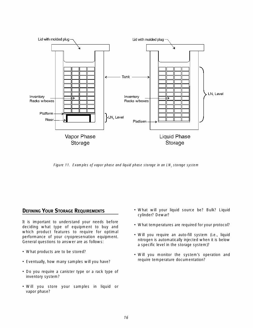
The range of liquid nitrogen storage options includesthe following:
• Complete long-term storage systems (Figure 12)with microprocessor liquid level controls andalarm systems and multiple styles of inventorycontrol systems
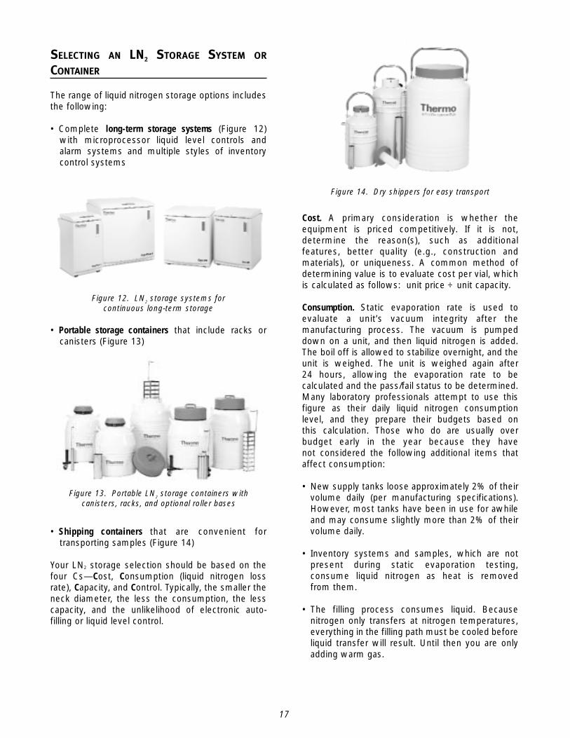
• Portable storage containers that include racks orcanisters (Figure 13)
• Shipping containers that are convenient fortransporting samples (Figure 14)
Your LN2 storage selection should be based on thefour Cs—Cost, Consumption (liquid nitrogen lossrate), Capacity, and Control. Typically, the smaller theneck diameter, the less the consumption, the lesscapacity, and the unlikelihood of electronic auto-filling or liquid level control.
Figure 14. Dry shippers for easy transport
Figure 12. LN2 storage systems for continuous long-term storage
Figure 13. Portable LN2 storage containers withcanisters, racks, and optional roller bases
18
You must weigh your own perceived value ofelectronic features, such as battery back-up and adefogger. Battery back-up allows continued liquidlevel and temperature monitoring during poweroutages for up to 72 hours. It is unclear how manytimes the battery would be able to energize thesolenoid for refilling liquid nitrogen during that 72 hour period. A defogger switch makes itpossible to clear the LN2 vapor in the storagecontainer for visibility and easy inventory retrieval.Some manufacturers include separate switches formanual fill and a defogger, while others offer both ofthese functions in one single manual fill switch.
Overall, the benefits need to be weighed against thecost of each feature because power is only requiredto support the electronic features (i.e., auto-filling,monitoring, and alarms) and is not required to safely store your samples. Power outages only demand that you revert to a manual filling modeof operation should power remain off for any lengthof time.
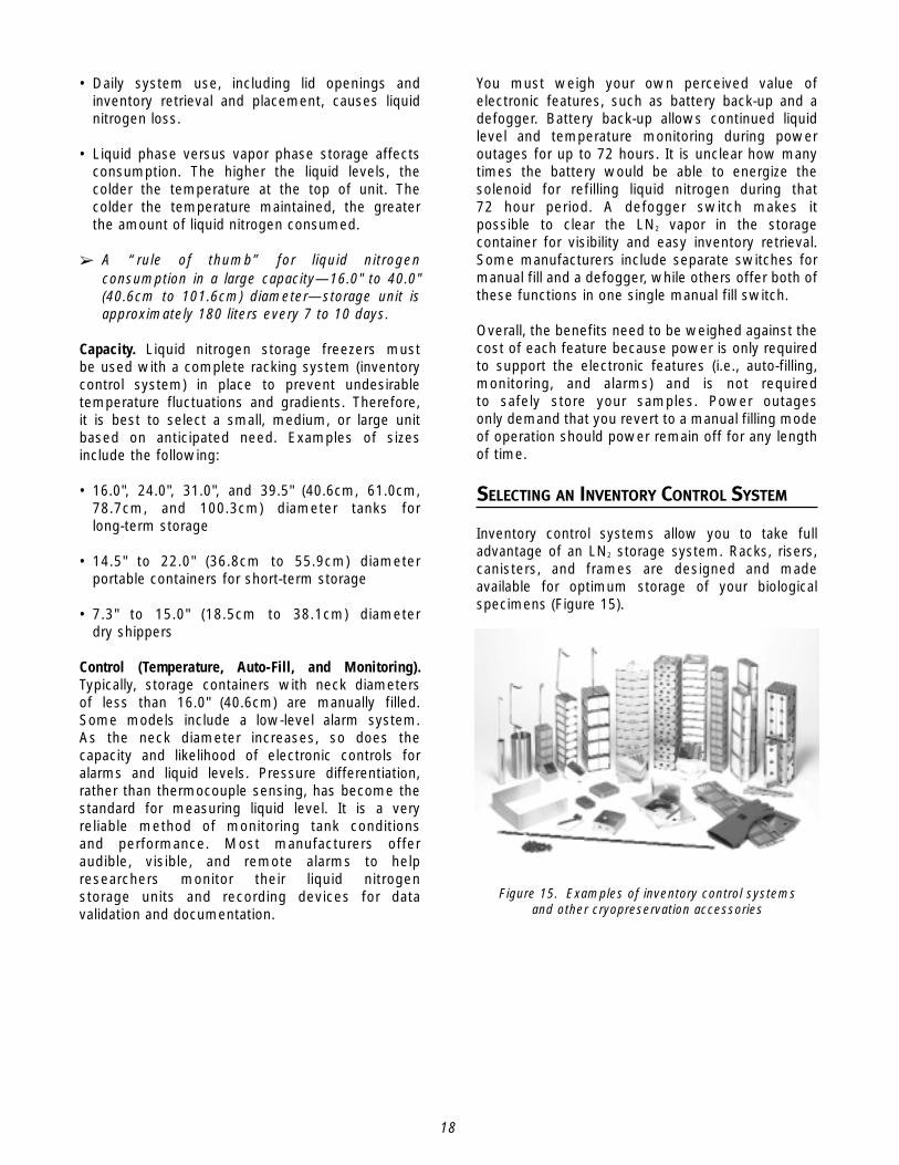
SELECTING AN INVENTORY CONTROL SYSTEM
Inventory control systems allow you to take fulladvantage of an LN2 storage system. Racks, risers,canisters, and frames are designed and madeavailable for optimum storage of your biologicalspecimens (Figure 15).
• Daily system use, including lid openings andinventory retrieval and placement, causes liquidnitrogen loss.
• Liquid phase versus vapor phase storage affectsconsumption. The higher the liquid levels, thecolder the temperature at the top of unit. Thecolder the temperature maintained, the greaterthe amount of liquid nitrogen consumed.
➢ A “rule of thumb” for liquid nitrogenconsumption in a large capacity—16.0" to 40.0"(40.6cm to 101.6cm) diameter—storage unit isapproximately 180 liters every 7 to 10 days.
Capacity. Liquid nitrogen storage freezers mustbe used with a complete racking system (inventorycontrol system) in place to prevent undesirabletemperature fluctuations and gradients. Therefore,it is best to select a small, medium, or large unitbased on anticipated need. Examples of sizesinclude the following:
• 16.0", 24.0", 31.0", and 39.5" (40.6cm, 61.0cm,78.7cm, and 100.3cm) diameter tanks forlong-term storage
• 14.5" to 22.0" (36.8cm to 55.9cm) diameterportable containers for short-term storage
• 7.3" to 15.0" (18.5cm to 38.1cm) diameter dry shippers
Control (Temperature, Auto-Fill, and Monitoring).Typically, storage containers with neck diametersof less than 16.0" (40.6cm) are manually filled.Some models include a low-level alarm system.As the neck diameter increases, so does thecapacity and likelihood of electronic controls foralarms and liquid levels. Pressure differentiation,rather than thermocouple sensing, has become thestandard for measuring liquid level. It is a veryreliable method of monitoring tank conditionsand performance. Most manufacturers offeraudible, visible, and remote alarms to helpresearchers monitor their liquid nitrogenstorage units and recording devices for datavalidation and documentation.
Figure 15. Examples of inventory control systems and other cryopreservation accessories
19
CONCLUSIONAn important general conclusion that has emergedfrom cryopreservation studies is that different typesof cells have different requirements for optimumpreservation. It is clear from the considerationsoutlined in this manual that successful, long-termcryopreservation of cells depends on developingprocedures in which optimum conditions for aconsiderable number of interrelated variables aredefined. Procedures have already been defined for awide variety of cells. However, intriguing andsometimes formidable problems still exist whenattempting to cryopreserve complex multicellulartissues. For example, extracellular ice formation,which is generally innocuous in single cellsuspensions, presents a significant hazard inmulticellular tissues but can be avoided byvitrification. Cryopreservation of multicellular tissuesis an area of ongoing research.
At this time, you should be able to preserve mostcell types and some selected tissue types bycombining the following:
• Your knowledge of, and/or experience with, thechemical control of ice formation
• The selection process for state-of-the-artequipment that effectively controls cooling andwarming conditions
• Selection and inventory configuration of reliableequipment to store your preserved samples untilthey are needed
• Knowledgeable sales associates to assist you withyour equipment selections
• Availability of process procedures to facilitate thefulfillment of regulatory requirements andimproving product quality
Most manufacturers offer inventory systems invapor or liquid phase capacities for 2.0ml, 4.0ml, and5.0ml samples. Typically, vertical racks, which allowyou to work conveniently in the vapor or liquidphase, are available in 11 or 13 box configurations,each with 100-cell dividers. Racks are commonlyshipped complete with boxes, dividers, and lockingrods. Risers are available for vapor phase storage.Custom inventory systems are often available.
Storage capacity is based on the cryo tank sizeand inventory configuration/layout. For example, a 16.0" (40.6cm) diameter CryoPlus Storage Systemcan hold 6,318 vials (2.0ml) in liquid phase storagewhen the following is selected: 6 arrowhead racks,each with 13 cardboard boxes (2.0" high) that have81 cells per divider.
13 boxes x 81 cells/divider = 1,053 cells1,053 cells x 6 racks = 6,318 cells (2.0 ml vials)
A 39.5" (100.3cm) diameter tank can store36,400 vials (2.0ml) in liquid phase storage whenthe following is selected: 28 vertical racks, eachwith 13 cardboard boxes (2.0" high) that have 100cells per divider.
13 boxes x 100 cells/divider = 1,300 cells1,300 cells x 28 racks = 36,400 cells (2.0ml vials)
Advantages of inventory rack systems include easyorganization of your samples; the ability to graspthe rack handle and pull out one rack at atime, leaving one hand free to retrieve yoursample(s); and minimizing exposure to ambienttemperature conditions.

21
This section outlines safety guidelines to followwhen using liquid nitrogen, as well as informationabout Installation and Operational Qualifications(IQ/OQ) that help you ensure proper equipmentinstallation and testing.
LIQUID NITROGEN SAFETY
The low temperature storage of biological materialspresents significant safety hazards. A littlecommon sense goes a long way when handlingliquid nitrogen, which displaces oxygen duringevaporation. Nitrogen gas is colorless, odorless, andtasteless. It cannot be detected by the humansenses and is breathed as if it were air. Breathingan atmosphere that contains less than 18% oxygencan cause dizziness and quickly lead tounconsciousness and death.
EXPLOSION
Liquid nitrogen is a cryogen with a boiling point of-196C (-320F). When removed from a liquid nitrogenatmosphere, improperly sealed sample containersmay explode. Placing containers in vapor phasenitrogen for several hours before immersing them inliquid nitrogen minimizes the risk of explosion.
CONTAMINATION
If the container being immersed in liquid nitrogencontains hazardous biological materials, thecontainer should be thawed and opened in abiological safety cabinet. Broken containers withinstorage freezers may be a risk due to contaminantsurvival. Protocols for decontamination should bedeveloped for immediate corrective action ifcontamination occurs.
PROTECTIVE CLOTHING
A protective face covering, insulated gloves, andlong sleeved clothing help prevent unnecessaryexposure to liquid nitrogen.
SAFETY RECOMMENDATIONS
Always consider the following when working withliquid nitrogen:
• Use only containers designed for low temperatureliquids.
• Do not seal or prevent liquid nitrogen fromventing.
• Use solid (never hollow) rods as measurementsticks.
• Use liquid nitrogen in well ventilated areas only.
• Do not overfill containers.
IQ/OQ PROCEDURES
Reasons to validate processes include improvingcustomer satisfaction, reducing costs, improvingproduct quality, and fulfilling regulatoryrequirements. A validated process, coupled withprocess design control can reduce developmenttime, which could lead to a faster time to market fora product. A properly validated and controlledinstallation process will yield a better performingproduct and is likely to result in fewer complaintsand recalls.
Methods and procedures for developing Installationand Operational Qualifications vary from company tocompany. While some customers follow specificformats for equipment in their institution, manymanufacturers make IQ/OQ procedures availablewith their individual equipment as a point ofcustomer service. IQ/OQ procedures are available for Thermo Electron’s CryoMed Freezersand Cryo/CryoPlus LN2 Storage Systems.These procedures, which meet the requirements ofISO 9001, include fully detailed checklists toqualify equipment setup and use. A document diskis included for easy process customization.
PART 3: SAFETY AND QUALITY CONTROL
22
INSTALLATION QUALIFICATION
Simply put, IQ answers the question “Is it installedcorrectly?” Important considerations in determiningthis qualification are as follows:
• Equipment design features (construction,cleanability, etc.)
• Installation conditions (wiring, utilities,functionality, etc.)
• Calibration, preventive maintenance, andcleaning schedules
• Safety features
• Supplier documentation, prints, drawings,and manuals
• Software documentation
• Spare parts list
• Environmental conditions (ambient temperature,exhaust requirements/oxygen supply)
Sometimes quality control activities are conductedat the manufacturer’s site before equipment isshipped. For example, equipment manufacturersmay perform test runs at their facilities and analyzethe results to determine if the equipment is readyfor delivery. These studies can be used as guidesto obtain basic data and to supplement yourinstallation qualification.
OPERATIONAL QUALIFICATION
In the OQ phase, process parameters are challengedto assure that they will result in a productthat meets defined requirements under anticipatedmanufacturing conditions. Considerations includethe following:
• Process control limits (time, temperature,pressure, linespeed, setup conditions, etc.)
• Software
• Raw material specifications
• Operating procedures
• Control procedures
• Preventive maintenance
• Training
• Cleaning
• Calibration
• Evaluations for potential failure modes and worstcase conditions
An Installation Qualification helps ensure that yourequipment is installed safely and properly. An Operational Qualification addresses equipmentuse and maintenance.
Another type of qualification procedure—aPerformance Qualification (PQ)—is specific toan individual’s or an organization’s work. Typically, PQ procedures are not provided byequipment manufacturers.
23
Kroener, C. and B. Luyet. “Discontinuous change inexpansion coefficient at the glass transitiontemperature in aqueous solutions of glycerol.”Biodynamica 10: 41-45, 1966a.
Kroener, C. and B. Luyet. “Formation of cracksduring the vitrification of glycerol solutions anddisappearance of the cracks during rewarming.”Biodynamica 10: 47-51, 1966b.
Lovelock, J. E. “The mechanism of the protectiveaction of glycerol against haemolysis by freezing andthawing.” Biochim Biophys Acta 11: 28, 1953.
Mazur, P. “Freezing of living cells: mechanisms andimplications.” Am J Physiol. 247: 125, 1984.
Mazur, P. “Fundamental cryobiology and thepreservation of organs by freezing.” In OrganPreservation for transplantation. (Eds. A. M. Karowand D. E. Pegg), Marcel Dekker, New York, pp. 143-175, 1981.
Miller, R. H. and P. Mazur. “Survival of frozen –thawed human red cells as a function of cooling andwarming velocities.” Cryobiology 13: 404-14, 1976.
Rajotte, R., T. Shnitka, E. Liburd, J. Dossetor, andW. Voss. “Histological studies on culturedcanine heart valves recovered from -196C.”Cryobiology 14: 15-22, 1977.
Rubinsky, B., C. Lee, J. Bastacky, and G. Onik. “Theprocess of freezing in the liver and the mechanismsof damage.” In Proceedings, CRYO 87-24th AnnualMeeting, 1987.
Schneider, U. and P. Mazur. “Relative influence ofunfrozen fraction and salt concentration on thesurvival of slowly frozen eight-cell mouseembryoes.” Cryobiology 24: 17-41, 1987.
Taylor, M. J. “Biology of cell survival in the cold.”9n: Eurekah and Graft, Landes Bioscience, (inPress) 2001.
Taylor, M. J., R. N. Campbell, R. N. Rutledge, andK. G. M. Brockbank. “Comparison of UNISOL withEuroCollins solution as a vehicle solution forcryoprotectants.” Transpl Proc., 33: 677-679, 2001.
Adam, M, J. F. Hu, P. Lange, and L. Wolfinbarger.“The effect of liquid nitrogen submersion oncryopreserved human heart valves.” Cryobiology 27:605-614, 1990.
Brockbank, K. G. M. “Essentials of cryobiology.”In Principles of Autologous, Allogeneic,and Cryopreserved Venous Transplantation.(Ed. K. G. M. Brockbank), RG Landes Company,Austin, TX (Medical Intelligence Unit Series) andSpringer-Verlag, 91-102, 1995.
Brockbank, K. G. M. “Method for cryopreservingblood vessels.” U.S. Patent 5,145,769, and Patent5,158,867, 1992.
Brockbank, K. G. M., J. F. Carpenter, and P. E.Dawson. “Effects of storage temperature onviable bioprosthetic heart valves.” Cryobiology 29:537, 1992.
Brockbank, K. G. M. and K. M. Smith. “Synergistic interaction of low-molecular-weightpolyvinylpyrrolidones with dimethyl sulfoxide duringcell preservation.” Transplant Proc. 25: 3185, 1993.
Fahy, G. M. “Vitrification.” In Low TemperatureBiotechnology: Emerging Applications andEngineering Contributions. (Eds. J. J. McGrathand K. R. Diller), New York: ASME, p. 113, 1988.
Farrant, J., H. Lee, and C. A. Walter. “Effects ofinteractions between cooling and rewarmingconditions on survival of cells.” In The Freezing ofMammalian Embryos. CIBA Foundation Symposium52 (new series). (Eds. K. Elliot and J. Whelan)pp. 49-67. Elsevier, Amsterdam, 1977b.
Farrant, J., C. A. Walter, H. Lee, and L. E. McGann.“Use of two-step cooling procedures toexamine factors influencing cell survivalfollowing freezing and thawing.” Cryobiology 1977;14: 273-286, 1977a.
Karow, A. M. “Biophysical and chemicalconsiderations in cryopreservation.” In OrganPreservation for Transplantation. (Eds. A. M.Karow and D. E. Pegg), Dekker, New York, p. 113,1981. Karow, A. M. and O. Carrier. “Effects ofcryoprotectant compounds on mammalian heartmuscle”. Surg Gynecol Obstet 128: 571, 1969.
REFERENCES
24
Taylor, M. J., A. M. Elrifai, and J. E. Bailes.“Hypothermia in relation to the acceptable limitsof ischemia for bloodless surgery.” In Advances inLow Temperature Biology. (Ed. Steponkus P. K.),Vol 3. pp. 1-64. JAI Press, London UK andGreenwich CT, 1996.
Taylor, M. J. and C. J. Hunt. “A new preservationsolution for storage of corneas at lowtemperatures.” Curr Eye Res 4(9): 963-973, 1985.
Whittingham, D. G., S. P. Leibo, and P. Mazur.“Survival of mouse embryos frozen to -196C and-269C.” Science, NY 178: 411-14, 1972.
Wolfinbarger L., M. Adam, P. Lange, and J. F. Hu.“Microfractures in cryopreserved heart valves: valvesubmersion in liquid nitrogen revisited.” Applicationsof Cryogenic Technology, Plenum Press,10: 227-233, 1991.


Controlled Environment EquipmentP.O. Box 649 • Marietta, OH 45750740-373-4763 • Fax: 740-373-6770Toll Free USA and Canada 866-984-3766
About Thermo
A world leader in high-tech instruments, Thermo ElectronCorporation helps life science, laboratory, and industrialcustomers advance scientific knowledge, enable drugdiscovery, improve manufacturing processes, and protectpeople and the environment with instruments, scientificequipment, services, and software solutions.
Based in Waltham, Massachusetts, Thermo Electron hasrevenues of more than $2 billion, and employsapproximately 11,000 people in 30 countries worldwide. For more information, visit www.thermo.com.
© 2004 Thermo Electron Corporation. All rights reserved. Trademarks and registered trademarks (except UNISOL) are the property of Thermo Electron Corporation and its subsidiaries. Specifications, terms, and pricingare subject to change. Not all products are available in all countries. Please consult your local sales representative for details.
Rev. 1, 5/04 2500
www.thermo.com