CROSS GEAR PUMPS/ 40 MOTORS - Northern … GEAR PUMPS/ MOTORS 40 SERIES GEAR PUMP - DELIVERY...
7
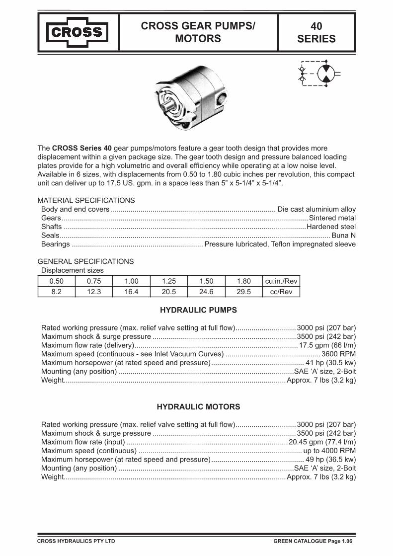
CROSS GEAR PUMPS/ MOTORS 40 SERIES The CROSS Series 40 gear pumps/motors feature a gear tooth design that provides more displacement within a given package size. The gear tooth design and pressure balanced loading plates provide for a high volumetric and overall efficiency while operating at a low noise level. Available in 6 sizes, with displacements from 0.50 to 1.80 cubic inches per revolution, this compact unit can deliver up to 17.5 US. gpm. in a space less than 5” x 5-1/4” x 5-1/4”. MATERIAL SPECIFICATIONS Body and end covers .................................................................................. Die cast aluminium alloy Gears .......................................................................................................................... Sintered metal Shafts ........................................................................................................................ Hardened steel Seals...................................................................................................................................... Buna N Bearings ................................................................. Pressure lubricated, Teflon impregnated sleeve GENERAL SPECIFICATIONS Displacement sizes 0.50 0.75 1.00 1.25 1.50 1.80 cu.in./Rev 8.2 12.3 16.4 20.5 24.6 29.5 cc/Rev HYDRAULIC PUMPS Rated working pressure (max. relief valve setting at full flow) .............................. 3000 psi (207 bar) Maximum shock & surge pressure ....................................................................... 3500 psi (242 bar) Maximum flow rate (delivery) ................................................................................. 17.5 gpm (66 l/m) Maximum speed (continuous - see Inlet Vacuum Curves) ............................................... 3600 RPM Maximum horsepower (at rated speed and pressure) .............................................. 41 hp (30.5 kw) Mounting (any position) .......................................................................................SAE ‘A’ size, 2-Bolt Weight.............................................................................................................. Approx. 7 lbs (3.2 kg) HYDRAULIC MOTORS Rated working pressure (max. relief valve setting at full flow) .............................. 3000 psi (207 bar) Maximum shock & surge pressure ....................................................................... 3500 psi (242 bar) Maximum flow rate (input) ................................................................................ 20.45 gpm (77.4 l/m) Maximum speed (continuous) ................................................................................. up to 4000 RPM Maximum horsepower (at rated speed and pressure) .............................................. 49 hp (36.5 kw) Mounting (any position) .......................................................................................SAE ‘A’ size, 2-Bolt Weight.............................................................................................................. Approx. 7 lbs (3.2 kg) CROSS HYDRAULICS PTY LTD GREEN CATALOGUE Page 1.06
Transcript of CROSS GEAR PUMPS/ 40 MOTORS - Northern … GEAR PUMPS/ MOTORS 40 SERIES GEAR PUMP - DELIVERY...
CROSS GEAR PUMPS/MOTORS
40 SERIES
The CROSS Series 40 gear pumps/motors feature a gear tooth design that provides more displacement within a given package size. The gear tooth design and pressure balanced loading plates provide for a high volumetric and overall efficiency while operating at a low noise level. Available in 6 sizes, with displacements from 0.50 to 1.80 cubic inches per revolution, this compact unit can deliver up to 17.5 US. gpm. in a space less than 5” x 5-1/4” x 5-1/4”.
MATERIAL SPECIFICATIONSBody and end covers.................................................................................. Die cast aluminium alloyGears..........................................................................................................................Sintered metalShafts ........................................................................................................................Hardened steelSeals...................................................................................................................................... Buna NBearings ................................................................. Pressure lubricated, Teflon impregnated sleeve
GENERAL SPECIFICATIONSDisplacement sizes
0.50 0.75 1.00 1.25 1.50 1.80 cu.in./Rev8.2 12.3 16.4 20.5 24.6 29.5 cc/Rev
HYDRAULIC PUMPS
Rated working pressure (max. relief valve setting at full flow)..............................3000 psi (207 bar)Maximum shock & surge pressure ....................................................................... 3500 psi (242 bar)Maximum flow rate (delivery)................................................................................. 17.5 gpm (66 l/m)Maximum speed (continuous - see Inlet Vacuum Curves) ............................................... 3600 RPMMaximum horsepower (at rated speed and pressure).............................................. 41 hp (30.5 kw)Mounting (any position) .......................................................................................SAE ‘A’ size, 2-BoltWeight..............................................................................................................Approx. 7 lbs (3.2 kg)
HYDRAULIC MOTORS
Rated working pressure (max. relief valve setting at full flow)..............................3000 psi (207 bar)Maximum shock & surge pressure ....................................................................... 3500 psi (242 bar)Maximum flow rate (input) ................................................................................ 20.45 gpm (77.4 l/m)Maximum speed (continuous) ................................................................................. up to 4000 RPMMaximum horsepower (at rated speed and pressure).............................................. 49 hp (36.5 kw)Mounting (any position) .......................................................................................SAE ‘A’ size, 2-BoltWeight..............................................................................................................Approx. 7 lbs (3.2 kg)
CROSS HYDRAULICS PTY LTD GREEN CATALOGUE Page 1.06
CROSS GEAR PUMPS/MOTORS
40 SERIES
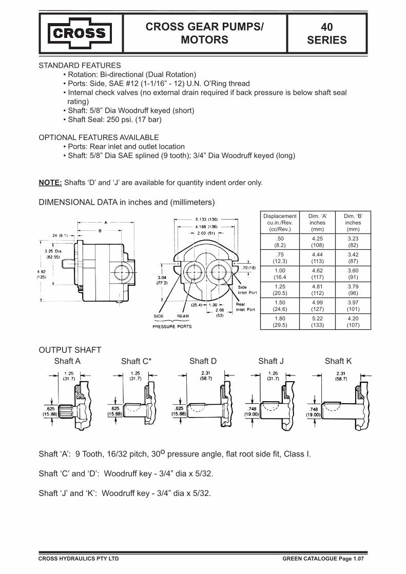
STANDARD FEATURES • Rotation: Bi-directional (Dual Rotation) • Ports: Side, SAE #12 (1-1/16” - 12) U.N. O’Ring thread • Internal check valves (no external drain required if back pressure is below shaft seal rating) • Shaft: 5/8” Dia Woodruff keyed (short) • Shaft Seal: 250 psi. (17 bar)
OPTIONAL FEATURES AVAILABLE • Ports: Rear inlet and outlet location • Shaft: 5/8” Dia SAE splined (9 tooth); 3/4” Dia Woodruff keyed (long)
NOTE: Shafts ‘D’ and ‘J’ are available for quantity indent order only.
DIMENSIONAL DATA in inches and (millimeters)Displacement
cu.in./Rev.(cc/Rev.)
Dim. ‘A’inches(mm)
Dim. ‘B’inches(mm)
.50(8.2)
4.25(108)
3.23(82)
.75(12.3)
4.44(113)
3.42(87)
1.00(16.4
4.62(117)
3.60(91)
1.25(20.5)
4.81(112)
3.79(96)
1.50(24.6)
4.99(127)
3.97(101)
1.80(29.5)
5.22(133)
4.20(107)
OUTPUT SHAFTShaft A Shaft C* Shaft D Shaft J Shaft K
Shaft ‘A’: 9 Tooth, 16/32 pitch, 30o pressure angle, flat root side fit, Class I.
Shaft ‘C’ and ‘D’: Woodruff key - 3/4” dia x 5/32.
Shaft ‘J’ and ‘K’: Woodruff key - 3/4” dia x 5/32.
CROSS HYDRAULICS PTY LTD GREEN CATALOGUE Page 1.07
CROSS GEAR PUMPS/MOTORS
40 SERIES
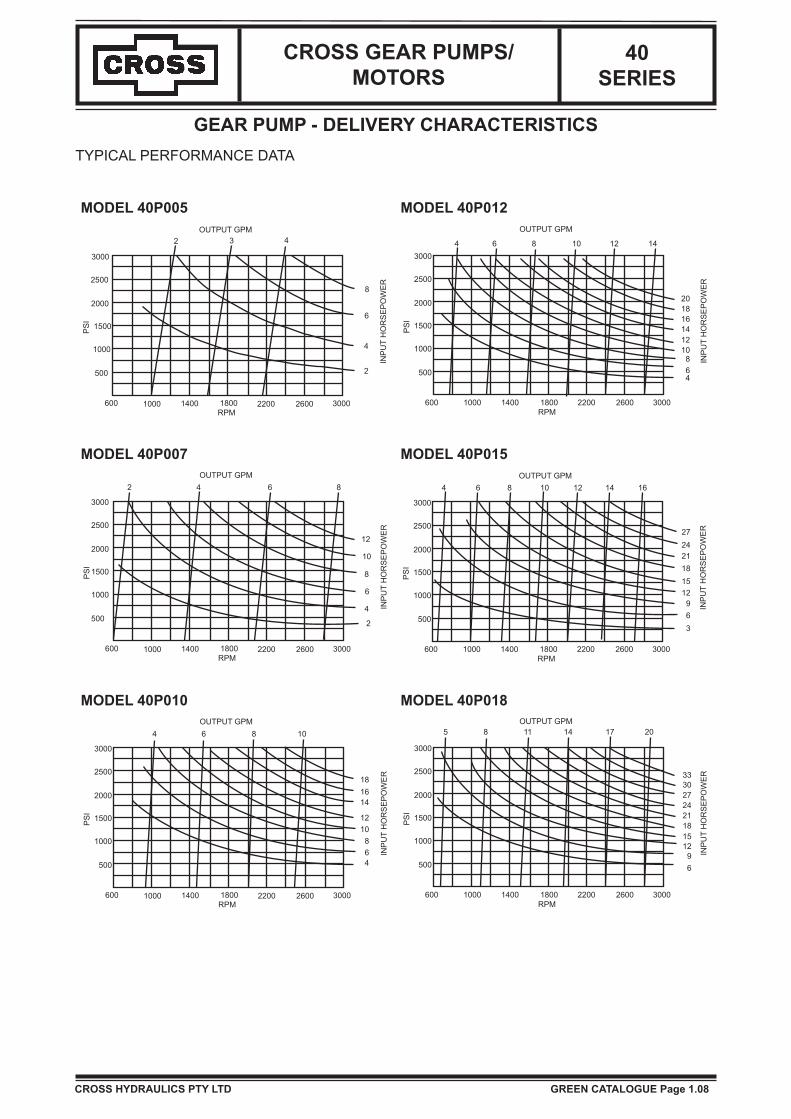
GEAR PUMP - DELIVERY CHARACTERISTICSTYPICAL PERFORMANCE DATA
CROSS HYDRAULICS PTY LTD GREEN CATALOGUE Page 1.08
MODEL 40P005 MODEL 40P012
600 1000 1400 1800 2200 2600 3000RPM
500
1000
1500
2000
2500
3000
PSI
2
OUTPUT GPM
INPUTHORSEPOWER
2 3 4
4
6
8
600 1000 1400 1800 2200 2600 3000RPM
500
1000
1500
2000
2500
3000
PSI
6
OUTPUT GPM
INPUTHORSEPOWER
4 6 8 10 12 14
4
8101214161820
MODEL 40P007 MODEL 40P015
600 1000 1400 1800 2200 2600 3000RPM
500
1000
1500
2000
2500
3000
PSI
4
OUTPUT GPM
INPUTHORSEPOWER
2 4 6 8
2
6
8
10
12
600 1000 1400 1800 2200 2600 3000RPM
500
1000
1500
2000
2500
3000
PSI
OUTPUT GPM
INPUTHORSEPOWER
4 6 8 10 12 14 16
369121518212427
MODEL 40P010 MODEL 40P018
600 1000 1400 1800 2200 2600 3000RPM
500
1000
1500
2000
2500
3000
PSI
4
OUTPUT GPM
INPUTHORSEPOWER
4 6 8 10
681012
141618
600 1000 1400 1800 2200 2600 3000RPM
500
1000
1500
2000
2500
3000
PSI
OUTPUT GPM
INPUTHORSEPOWER
5 8 11 14 17 20
691215182124273033
CROSS GEAR PUMPS/MOTORS
40 SERIES
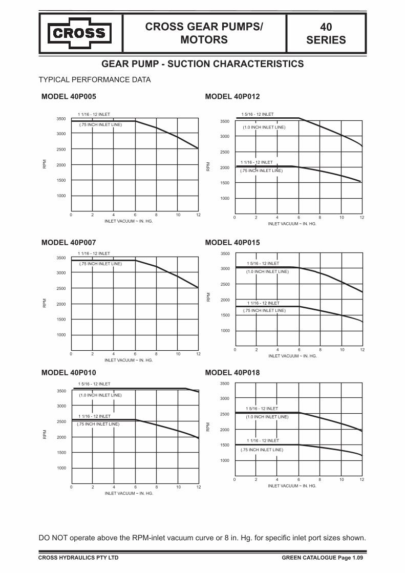
GEAR PUMP - SUCTION CHARACTERISTICSTYPICAL PERFORMANCE DATA
DO NOT operate above the RPM-inlet vacuum curve or 8 in. Hg. for specific inlet port sizes shown.
CROSS HYDRAULICS PTY LTD GREEN CATALOGUE Page 1.09
MODEL 40P005 MODEL 40P012
1000
1500
2000
2500
3000
3500
0 2 4 6 8 10 12INLET VACUUM ~ IN. HG.
1 1/16 - 12 INLET
(.75 INCH INLET LINE)
RPM
1000
1500
2000
2500
3000
3500
0 2 4 6 8 10 12INLET VACUUM ~ IN. HG.
1 5/16 - 12 INLET
(1.0 INCH INLET LINE)
RPM 1 1/16 - 12 INLET
(.75 INCH INLET LINE)
MODEL 40P007 MODEL 40P015
1000
1500
2000
2500
3000
3500
0 2 4 6 8 10 12INLET VACUUM ~ IN. HG.
1 1/16 - 12 INLET
(.75 INCH INLET LINE)
RPM
1000
1500
2000
2500
3000
3500
0 2 4 6 8 10 12INLET VACUUM ~ IN. HG.
1 5/16 - 12 INLET
(1.0 INCH INLET LINE)
RPM
1 1/16 - 12 INLET
(.75 INCH INLET LINE)
MODEL 40P010 MODEL 40P018
1000
1500
2000
2500
3000
3500
0 2 4 6 8 10 12INLET VACUUM ~ IN. HG.
1 5/16 - 12 INLET
(1.0 INCH INLET LINE)
RPM
1 1/16 - 12 INLET
(.75 INCH INLET LINE)
1000
1500
2000
2500
3000
3500
0 2 4 6 8 10 12INLET VACUUM ~ IN. HG.
1 5/16 - 12 INLET
(1.0 INCH INLET LINE)
RPM
1 1/16 - 12 INLET
(.75 INCH INLET LINE)
CROSS GEAR PUMPS/MOTORS
40 SERIES
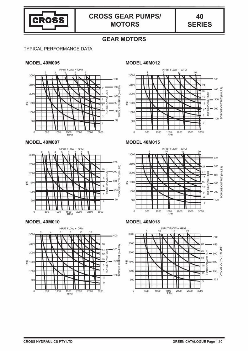
GEAR MOTORSTYPICAL PERFORMANCE DATA
CROSS HYDRAULICS PTY LTD GREEN CATALOGUE Page 1.10
MODEL 40M005 MODEL 40M012
0 500 1000 1500 2000RPM
2500 3000
1
230
603
490
51206
7 150
180
65432INPUT FLOW ~ GPM
3000
2500
2000
1500
1000
500
PSI
HORSEPOWEROUT
TORQUEOUTPUT(IN-LBS)
0
3000
2500
2000
1500
1000
500
PSI
500 1000 1500 2000RPM
2500 3000
INPUT FLOW ~ GPM
HORSEPOWEROUT
TORQUEOUTPUT(IN-LBS)
4 8 12 16
500
400
300
200
100
3
6
9
12
15
18
21
MODEL 40M007 MODEL 40M015
0 500 1000 1500 2000RPM
2500 3000
2 50
4
6
65432INPUT FLOW ~ GPM
3000
2500
2000
1500
1000
500
PSI
HORSEPOWEROUT
TORQUEOUTPUT(IN-LBS)
7 8 9
8
10
100
150
200
250
0
3000
2500
2000
1500
1000
500
PSI
500 1000 1500 2000RPM
2500 3000
INPUT FLOW ~ GPM
HORSEPOWEROUT
TORQUEOUTPUT(IN-LBS)
5 10 15 20
600
400
300
200
1003
6
9
12
15
18
21
24 500
MODEL 40M010 MODEL 40M018
0 500 1000 1500 2000RPM
2500 3000
2
4
642INPUT FLOW ~ GPM
3000
2500
2000
1500
1000
500
PSI
HORSEPOWEROUT
TORQUEOUTPUT(IN-LBS)
8 10 12400
300
200
16
1412
10
8
6
100
0
3000
2500
2000
1500
1000
500
PSI
500 1000 1500 2000RPM
2500 3000
INPUT FLOW ~ GPM
HORSEPOWEROUT
TORQUEOUTPUT(IN-LBS)
5 10 15 20
750
500
375
250
125
625
5
10
15
20
25
30

CROSS GEAR PUMPS/MOTORS
40 SERIES
GEAR MOTORS
TYPICAL PERFORMANCE DATA
STARTING ENGINE TORQUE (in. lbs.) vs. PRESSURE (PSI)
VOLUMETRIC EFFICIENCY (%) vs. RPM(TYPICAL)
CROSS HYDRAULICS PTY LTD GREEN CATALOGUE Page 1.11
0 500 1000 1500 2000 2500 3000R P M
70
75
80
85
90
95
100
VOLUMETRICEFFICIENCY~%
40M005
40M00740M010
40M012
40M01540M018
0 500 1000 1500 2000 2500 3000
PRESSURE ~ PSI
100
200
300
400
500
600
700
STARTINGTORQUE~IN.-LBS.
40M005
40M007
40M010
40M012
40M015
40M018

CROSS GEAR PUMPS/MOTORS
40 SERIES
HOW TO ORDER
Series Type SpecialOptions
Sizecu.in./rev x 0.1
Rotation Mounting ShaftSize & Type
Ports
Location Code
SizeInlet Outlet
40 P(Pump)
M(Motor)
ONone
H*250 psi
Shaft Seal
050710121518
D*Dual
RRight
LLeft
A*SAE ‘A’2-Bolt
A5/8”
SplineC*
5/8” Dia Keyed
D5/8” Dia Keyed (Long)
J3/4” Dia Keyed
K3/4” Dia Keyed (Long)
SA1-5/16”
UN O’Ring
1-1/16”UN
O’Ring
Side
SC*1-1/16”
UN O’Ring
1-1/16”UN
O’Ring
RB1-5/16”
UN O’Ring
1-1/16”UN
O’Ring
Rea
r
RD1-1/16”
UN O’Ring
1-1/16”UN
O’Ring
* Standard
EXAMPLE: 40PH10DACSCDescribes a Series 40 Gear Pump/Motor fitted with a high pressure shaft seal; a displacement of 1.0 cu.in./rev; Bi-directional rotation; SAE ‘A’ 2-Bolt Mount, 5/8” Dia keyed shaft and 1-1/16” UN O’Ring side Inlet & Outlet Ports.
NOTE: Series 40 Pumps only are stocked. Because of the high pressure shaft seal and the dual rotation feature they can be substituted where required for use as motors.When used as a motor a case drain connection is only required when the outlet/return pressure is likely to exceed 250 psi.
CROSS HYDRAULICS PTY LTD GREEN CATALOGUE Page 1.12

PART NUMBER DESCRIPTION SERIES1 4P0013001 Thrust Plate All
2
4P00120074P00120084P00120094P00120104P00120114P0012012
Driven Gear
40P/M00540P/M00740P/M01040P/M01240P/M01540P/M018
3
4P00110074P00110084P00110094P00110104P00110114P0011012
Drive Gear Assy9 Tooth Spline
40P/M00540P/M00740P/M01040P/M01240P/M01540P/M018
4P00110014P00110024P00110034P00110044P00110054P0011006
Drive Gear Assy5/8” Dia Keyed
40P/M00540P/M00740P/M01040P/M01240P/M01540P/M018
4P00110244P00110254P00110264P00110274P00110284P0011029
Drive Gear Assy3/4” Dia Keyed Long
40P/M00540P/M00740P/M01040P/M01240P/M01540P/M018
CHECK VALVESFOR DUALROTATION.
( REAR VIEW )
13
6 8 11 7 1 2
411
87153
12 10 9
VENT HOLE ON INLET( LOW PRESSURE SIDE )SINGLE ROTATION PUMPS ONLY.
A C D J K
CASE DRAIN PORT -USE WHEN BACK PRESSUREEXCEED SEAL RATING.( DUAL ROTATION ONLY )
TORQUE TO35 - 40 FT. LBS.
SERIES 40 GEAR PUMP and MOTOR Parts Exploded
PART NUMBER DESCRIPTION SERIES
4
4P00070014P00070024P00070034P0007004
Rear Cover Assy
All - RB PortingAll - RD PortingAll - SA PortingAll - SC Porting
5
4P00040014P00040024P00040034P00040044P00040054P0004006
Body
40P/M00540P/M00740P/M01040P/M01240P/M01540P/M018
6 4P0003001 Front Cover Assy All
7 5A0078 Loading Seal All
8 5A0048 Static Seal All
9 5A0081 Shaft Seal All
10 2A0466150 Retaining Ring All
11 2A0310604 Dowel Pin All
12
2A00796242A00796242A00796262A00796302A00796322A0079634
Cap Screw
40P/M00540P/M00740P/M01040P/M01240P/M01540P/M018
13 5A0067 Woodruff Key All
4P0017004 SEAL KIT All

Cross Gear Pumps & Motors
September 2007Page 8.01CROSS
CROSS CROSS
Model Gear Width Body Width
40P005 0.372” 0.779”
40P007 0.558” 0.965”
40P010 0.744” 1.151”
40P012 0.930” 1.337”
40P015 1.116” 1.523”
40P018 1.339” 1.746”
50P015 0.675” 1.082”
50P019 0.867” 1.274”
50P023 1.031” 1.438”
50P027 1.218” 1.625”
50P033 1.467” 1.874”
50P038 1.689” 2.096”
50P052 2.311” 2.718”
60P040 1.015” 1.518”
60P051 1.280” 1.783”
60P061 1.545” 2.048”
60P071 1.795” 2.298”
60P081 2.045” 2.548”
60P092 2.325” 2.828”
Field Identification:
Direction of rotation is marked on the unit. Stock number is a 6 digit starting with 3..... (date code and partial description noted as below) stamped on the flange.
Measure width of body or gears if unable to read computer stock number.
300000
CONTROL NUMBER(MAY INCLUDE DESCRIPTIVE NO.)
BODY WIDTH:MEASURE THIS AND REFERTO CHART
DIRECTION OF ROTATION= DUAL
P = PUMPM = MOTOR
DATE CODE
NO. OF WEEKS AFTERJAN 1.
YEAR
TESTERS CODE
FIRST 2 DIGITS OFDISPLACEMENT.
OMIT IF FULL DESCRIPTIVENUMBER IS USED.
23 P12 97 AB
PERFORMANCE DATA - PUMPS: GPM/RPM PERFORMANCE DATA - MOTORS: RPM/GPM
RPM 1000 1500 2000 2500 3000 GPM 5 10 15 20 30 50
MODEL GPM GPM GPM GPM GPM MODEL RPM RPM RPM RPM RPM RPM
40P00540P007
1.72.8
2.64.1
3.55.5
4.36.9
5.28.3
40M00540M007
17321155 2310
40P01040P012
3.74.9
6.57.3
7.49.7
9.212.1
11.014.6
40M01040M012
866693
17321386
25992079
40P01540P018
5.87.0
8.810.5
11.714.0
14.617.5
17.5 40M01540M018
577481
1155962
17321443
23101925 2887
50P01550P019
5.97.6
8.811.4
11.815.2
14.619.0
17.822.8
50M01550M019
684533
13681066
2052 1599
27362132
50P02350P027
9.010.7
13.616.0
18.121.4
22.626.7
27.132.0
50M02350M027
448379
896759
13441138
17921518
26882276
50P03350P03850P052
12.914.820.3
19.322.230.4
25.729.640.6
32.137.0
38.6 50M03350M03850M052
315274199
630547400
945821
12601094800
189016411199
27361999600
60P04060P051
15.820.1
23.730.1
31.640.1
39.450.2
47.360.2
60M04060M051
257202
513404
770606
1027807
15401211
25672018
60P06160P071
24.027.9
36.041.8
47.955.7
59.969.6
71.883.6
60M06160M071 169 338
291507436
676582
1014872
16901454
60P08160P092
31.836.0
47.654.1
63.572.1
79.4901
60M08160M092
255225
383337
510450
765 12751124674
Note: Above performance figures are approximate and are based on 2000 psi operating pressure. Operation on shaded areas is not recommended. Maximum speeds achievable using largest stepped port sizes. Refer to Green Catalogue page 1.02 for Pump Speed vs Port Size Limitations.

GENERAL TECHNICALThe CROSS fixed displacement, gear type pumps and motors have been designed, manufactured and tested to insure the highest quality. This manual has been prepared to assist in the application and installation in order to obtain optimum performance.
Rated working pressure................................ up to 3000 psiMaximum shock and surge pressure............ up to 3500 psiMaximum speed, continuous.............................. see chartsMinimum speed recommended.............................. 600 rpm
PERFORMANCE DATA - PUMPS: GPM/RPM PERFORMANCE DATA - MOTORS: RPM/GPMRPM 1000 1500 2000 2500 3000 GPM 5 10 15 20 30 50MODEL GPM GPM GPM GPM GPM MODEL RPM RPM RPM RPM RPM RPM40P00540P007
1.72.8
2.64.1
3.55.5
4.36.9
5.28.3
40M00540M007
17321155 2310
40P01040P012
3.74.9
6.57.3
7.49.7
9.212.1
11.014.6
40M01040M012
866693
17321386
25992079
40P01540P018
5.87.0
8.810.5
11.714.0
14.617.5
17.5 40M01540M018
577481
1155962
17321443
23101925 2887
50P01550P019
5.97.6
8.811.4
11.815.2
14.619.0
17.822.8
50M01550M019
684533
13681066
2052 1599
27362132
50P02350P027
9.010.7
13.616.0
18.121.4
22.626.7
27.132.0
50M02350M027
448379
896759
13441138
17921518
26882276
50P03350P03850P052
12.914.820.3
19.322.230.4
25.729.640.6
32.137.0
38.6 50M03350M03850M052
315274199
630547400
945821
12601094800
189016411199
27361999600
60P04060P051
15.820.1
23.730.1
31.640.1
39.450.2
47.360.2
60M04060M051
257202
513404
770606
1027807
15401211
25672018
60P06160P071
24.027.9
36.041.8
47.955.7
59.969.6
71.883.6
60M06160M071
169 338291
507436
676582
1014872
16901454
60P08160P092
31.836.0
47.654.1
63.572.1
79.4901
60M08160M092
255225
383337
510450
765 12751124674
NOTE: ABOVE PERFORMANCE FIGURES ARE APPROXIMATE AND ARE BASED ON 2000 PSI OPERATING PRESSURE. OPERATING IN SHADED AREAS IS NOT RECOMMENDED.
FOR DRIVE HP REQUIRED: Multiply flow (gpm) by pressure (psi) and divide by 1714. FOR MAX. PUMP SIZE: (for use with gas engine): Multiply rated engine HP by 1028 and divide by pressure (psi). This gives maximum flow rate (gpm). Select the nearest pump size from the above chart according to drive speed. FOR MOTOR DRIVE TORQUE: Multiply HP by 5252 and divide by RPM.
FOR HYD. MOTOR SIZE: Multiply torque (ft. lbs.) by 88 and divide by pressure (psi). This gives motor size in cu.in./rev. Select nearest motor size from the above chart. For full load starting, use a 10% larger motor size.
HP = GPM x PSI 1714
GPM = 1028 HP PSI
TORQUE = 5252 HP(ft. lbs.) RPM
DISP. = 88T PSI
CROSS GEAR PUMPS/MOTORS
CROSS HYDRAULICS PTY LTD GREEN CATALOGUE Page 1.01

CROSS GEAR PUMPS/MOTORS
OIL RECOMMENDATIONS: Premium quality anti-wear type oil with a viscosity between 100 and 200 SSU at operating temperatures. Automatic transmission fluids are acceptable. Do not use synthetic fluids.
FILTRATION: 25 micron filters are required with 10 micron preferred. If pump inlet filters are used, be certain inlet flow is not restricted. Cavitation will severely reduce pump life.
PUMP SPEED/PORT SIZE LIMITATIONS: If pumps are operated at speeds higher than shown below, cavitation and pump damage can occur.
PLUMBING SIZE RECOMMENDATIONS: The following is based on 4 ft./sec. inlet velocity and 15 ft./sec. outlet velocity.
SERIES & SIZE
PUMP INLET PORT SIZE
1-1/16 12 1-5/16 12 1-5/8 12 1-7/8 12 2” S.F.3/4” (12) 1” (16) 1-1/4” (20) 1-1/2” (24) 2”
3500 3500
40 S
ER
IES
53400 350072500 350010
12 2000 350015 1750 300018 1400 2500
50 S
ER
IES
15 3000 3000 300019 2300 3000 300023 2000 3000 3000
1700 2600 3000271400 2100 3000331200 1800 2700381000 1600 220052
60 S
ER
IES
40 2000 3000 30001750 2500 3000511400 2200 300061
71 1000 1900 300081 800 1600 260092 600 1400 2500
GPMPUMP INLET PUMP OUTLET
PIPE TUBE HOSE PIPE TUBE HOSE
5 3/4” 7/8” 3/4” 1/4” 3/8” 3/8”
10 1” 1” 1” 3/8” 1/2” 1/2”
15 1 1/4” 1 1/4” 1 1/4” 1/2” 5/8” 1/2”
20 1 1/2” 1 1/2” 1 1/2” 3/4” 3/4” 3/4”
25 1 1/2” 1 1/2” 1 1/2” 3/4” 7/8” 3/4”
30 1 3/4” 1 3/4” 1 3/4” 1” 1” 1”
35 2” 2” 2” 1” 1 1/4” 1”
40 2 1/4” 2 1/4” 2 1/4” 1 1/4” 1 1/4” 1 1/4”
50 2 1/2” 2 1/2” 2 1/2” 1 1/4” 1 1/2” 1 1/4”
75 3” 3” 3” 1 1/2” 1 3/4” 1 1/2”
Tube sizes are OD. Hose sizes are ID.Reduce plumbing size to match pump port size AT PUMP.
BASED ON INLET RESTRICTION (6” HG MAX. VACUUM)MOUNTING: Pumps an motors may be mounted in any position. DIRECT FLANGE MOUNTING: Mount directly to gear box or engine PTO, carefully inserting shaft and pilot into mating holes. Make certain that shaft size and type matches drive. FOOT MOUNT WITH COUPLING: Excessive wear and reduce life will occur due to misalignment. Minor misalignment can be compensated for by using a flexible coupling. FOOT MOUNT WITH BELT OR CHAIN DRIVE: Excessive wear will occur with misalignment.
MISALIGNMENT
ANGULAR OFF-SET(.005 T.I.R. MAX.)
ANGULAR OFF-SET
B
LOAD
RH ROTATION
INLET
A
LOAD
SIDE LOAD:
BI - DIRECTIONALROTATION
LOAD
CLOAD
L
Side loads resulting from belt or chain drives should be kept as close to the housing as possible (ie., keep dimen-sion ‘L’ to a minimum). For maximum life, loads should be applied at quadrant ‘A’ for pumps (RH), quadrant ‘B’ for motors (RH), ‘A’ for LH motors, ‘B’ for LH pumps, and ‘C’ for bi-rotational motors.
CROSS HYDRAULICS PTY LTDCROSS HYDRAULICS PTY LTD GREEN CATALOGUE Page 1.02

CROSS GEAR PUMPS/MOTORS
DIRECTION OF ROTATION:Right hand (RH) or left hand (LH) pumps or motors, if oper-ated in the wrong direction, will result in THE IMMEDIATE FAILURE of the shaft seal. Pump and motor rotation is NOT field reversible. Dual rotation (D) units may be operated in either direction.
They also can be operated as either a pump or motor. The correct direction of rotation can be determined by the model number stamped on the front cover.
DRAIN PORT CONNECTION: If the motor outlet port pressure exceeds the rating of the shaft seal (20 psi standard), the drain port must be connected directly to the reservoir. Dual rotation pumps have drain port connections for use as motors.
START-UP PROCEDURES:1. Prior to installation, check pump or motor for possible damage in shipping or handling.2. Install unit, tighten fittings and fill reservoir with clean fluid.3. Fill pump/motor with fluid through drain port connection or inlet port.4. Start engine and run at lowest speed. Check system for air (suction) leaks and oil leaks. (Use a piece of cardboard or wood when searching for possible oil leaks, DO NOT USE HANDS). Bleed air from system if necessary. Operate system at normal speed.5. Gradually increase load to normal, checking for leaks, abnormal noises, binding, etc. Operate system for 15 minutes. Shut off and check filters. Clean or replace as necessary.
MAINTENANCE:1. Clean or replace filters on a regular basis, as necessary.2. Check for presence of water in oil (cloudy or milky appearance) and for presence of air (foamy oil). A rancid odour indicates excessive heating of the oil.3. Check reservoir regularly for proper level. Fill as needed. Repair leaks.
FOR ALL PUMPS AND MOTORS, REFER TO SPECIFIC SPECIFICATION SHEETS FOR ADDITIONAL DATA AND LIST OF OPTIONS AVAILABLE.
NOTE: If chronic shaft seal failure occurs: 1. Check direction of rotation. 2. Check outlet port or drain port pressure. 3. Replace shaft seal with higher pressure rating seal. (See available seal kits)
INLETPORT
RH
CLOCKWISE
OUTLETPORT
INLETPORT
COUNTERCLOCKWISE
LH
14 18NPTF
CROSS HYDRAULICS PTY LTD GREEN CATALOGUE Page 1.03

CROSS GEAR PUMPS/MOTORS
HELPFUL NOMOGRAPHS
PUMP and MOTOR HORSEPOWER PIPE FLOW CAPACITY
HP = PSI X GPM X 0.000583
PUMP DRIVE = THL. HP : EFFICIENCYMOTOR OUTPUT = THL. HP X EFFICIENCY
AREA = GPM X 0.3208 VELOCITY (FT./SEC.)
*Recommendations are for oils having a maximum viscosity of 315 S.S.U. at 100 F operating at temperatures between 65 F and 155 F.
GPM in these NOMOGRAPHS relates to US. GPM.
1 US. GPM = 3.79 Litres
CROSS HYDRAULICS PTY LTD GREEN CATALOGUE Page 1.04

CROSS GEAR PUMPS/MOTORS
HELPFUL NOMOGRAPHS
HYDRAULIC MOTOR TORQUE HYDRAULIC MOTOR SPEED
TORQUE = DISPL. X PRESSURE 2
GPM in these NOMOGRAPHS relates to US. GPM.
1 US. GPM = 3.79 Litres
FLOW RATE = SPEED X DISPL. 231
CROSS HYDRAULICS PTY LTD GREEN CATALOGUE Page 1.05