Creation Of A Warfighting In Complex Terrain System Of ... · Creation Of A Warfighting In Complex...
8
SimTecT 2008 Refereed Creation Of A Warfighting In Complex Terrain System Of Systems Analysis Environment Shane D Arnott Technical Fellow Director – The Portal Boeing Defence UK [email protected] John Winskill Operations Analyst The Portal Boeing Defence UK [email protected] Anthony Lines Systems Engineer The Portal QinetiQ UK [email protected] Andrew McMahon Software Engineer The Portal Boeing Defence UK [email protected] Abstract. Simulation of land warfare in complex terrain (i.e. urban and semi-rural landscapes of Iraq and Afghanistan) is a difficult task, presenting new challenges beyond the “traditional” simulation area of interest of conventional warfare in the air and maritime domain. To support the United Kingdom Ministry of Defence (MoD) Future Rapid Effect System (FRES) program, just such an environment was required to assist in understanding of system of systems integration, requirements trade and concept of operations analysis activities. The requirement was for a warfighter-in-the-loop environment to enable trade-offs of vehicle mounted systems such as sensors, communications and battle management systems with their relationship to off-board sensors and effectors in order to assess the system of system impact and effectiveness of the individual and collection of systems towards increased overall force effectiveness against asymmetric and symmetric threats. The difficulties faced in creation of this environment are examined in detail including issues associated with “system of systems” assessment and the constraints of current technology on various fronts. Due to the complexity of the requirement, a novel coupling of non-traditional gaming technology was employed in-conjunction with more traditional Computer Generated Forces (CGF) to provide the tactical environment, derived from commercial sources. In order to provide the networking, battle management and analysis functions proprietary technology was required as no commercial equivalents were found to be suitable. The resulting architecture and employment on the FRES System of Systems Integrator program for analyses for the Ministry of Defence across a number of successful experiments is presented. 1 INTRODUCTION The Future Rapid Effects System (FRES) is the UK Ministry of Defence’s (MoD) programme to deliver a fleet of (up to) 3,000 wheeled and tracked armoured vehicles to the British Army that is rapidly deployable, network-enabled, capable of operating across the spectrum of operations; and protected against the most likely threats. The total FRES fleet is expected to comprise fives families of vehicles: Utility, Reconnaissance, Fires, Manoeuvre Support and a family of simpler variants known as the ‘Basic Capability Unit’. Due to the complexity of the project a System of System Integrator (SOSI) was been selected to assist the MoD in selection of the vehicles and electronic architecture. The FRES SOSI contract was awarded to a joint team of Thales and Boeing. As part of the FRES SOSI program Boeing invested in creation of an environment to enable system of system requirements trades and assessment. This paper describes the issues associated with system of systems assessment, simulation ground warfare in complex terrain and the final solution system successfully used on the FRES program. 2 SYSTEM OF SYSTEMS ANALYSIS Systems Engineering (SE) is an interdisciplinary approach and means to enable the realisation of successful systems. It is a well founded field that is traced back to 1940’s (Schlager, J.1956) with Bell laboratories being credited with the first incarnation. In response to ever growing complexity and advances in connectivity technologies, the System of Systems Engineering (SoSE) discipline has grown and is being embraced by many industries, in-particular the Defence industry (Crossley 2004), with companies such as Boeing investing in the development of processes and people in the trade It is important to note that SE is not being super seeded by SoSE, but that they are related although different fields. Whereas SE focuses on building the system right, SoSE focuses on choosing the right system(s) to satisfy the requirements.
Transcript of Creation Of A Warfighting In Complex Terrain System Of ... · Creation Of A Warfighting In Complex...

SimTecT 2008 Refereed
Creation Of A Warfighting In Complex Terrain System Of Systems Analysis Environment
Shane D Arnott Technical Fellow
Director – The Portal Boeing Defence UK
John Winskill Operations Analyst
The Portal Boeing Defence UK
Anthony Lines Systems Engineer
The Portal QinetiQ UK
Andrew McMahon Software Engineer
The Portal Boeing Defence UK
Abstract. Simulation of land warfare in complex terrain (i.e. urban and semi-rural landscapes of Iraq and Afghanistan) is a difficult task, presenting new challenges beyond the “traditional” simulation area of interest of conventional warfare in the air and maritime domain. To support the United Kingdom Ministry of Defence (MoD) Future Rapid Effect System (FRES) program, just such an environment was required to assist in understanding of system of systems integration, requirements trade and concept of operations analysis activities.
The requirement was for a warfighter-in-the-loop environment to enable trade-offs of vehicle mounted systems such as sensors, communications and battle management systems with their relationship to off-board sensors and effectors in order to assess the system of system impact and effectiveness of the individual and collection of systems towards increased overall force effectiveness against asymmetric and symmetric threats. The difficulties faced in creation of this environment are examined in detail including issues associated with “system of systems” assessment and the constraints of current technology on various fronts. Due to the complexity of the requirement, a novel coupling of non-traditional gaming technology was employed in-conjunction with more traditional Computer Generated Forces (CGF) to provide the tactical environment, derived from commercial sources. In order to provide the networking, battle management and analysis functions proprietary technology was required as no commercial equivalents were found to be suitable.
The resulting architecture and employment on the FRES System of Systems Integrator program for analyses for the Ministry of Defence across a number of successful experiments is presented.
1 INTRODUCTION The Future Rapid Effects System (FRES) is the UK Ministry of Defence’s (MoD) programme to deliver a fleet of (up to) 3,000 wheeled and tracked armoured vehicles to the British Army that is rapidly deployable, network-enabled, capable of operating across the spectrum of operations; and protected against the most likely threats. The total FRES fleet is expected to comprise fives families of vehicles: Utility, Reconnaissance, Fires, Manoeuvre Support and a family of simpler variants known as the ‘Basic Capability Unit’.
Due to the complexity of the project a System of System Integrator (SOSI) was been selected to assist the MoD in selection of the vehicles and electronic architecture. The FRES SOSI contract was awarded to a joint team of Thales and Boeing.
As part of the FRES SOSI program Boeing invested in creation of an environment to enable system of system requirements trades and assessment. This paper describes the issues associated with system of systems
assessment, simulation ground warfare in complex terrain and the final solution system successfully used on the FRES program.
2 SYSTEM OF SYSTEMS ANALYSIS Systems Engineering (SE) is an interdisciplinary approach and means to enable the realisation of successful systems. It is a well founded field that is traced back to 1940’s (Schlager, J.1956) with Bell laboratories being credited with the first incarnation.
In response to ever growing complexity and advances in connectivity technologies, the System of Systems Engineering (SoSE) discipline has grown and is being embraced by many industries, in-particular the Defence industry (Crossley 2004), with companies such as Boeing investing in the development of processes and people in the trade
It is important to note that SE is not being super seeded by SoSE, but that they are related although different fields. Whereas SE focuses on building the system right, SoSE focuses on choosing the right system(s) to satisfy the requirements.
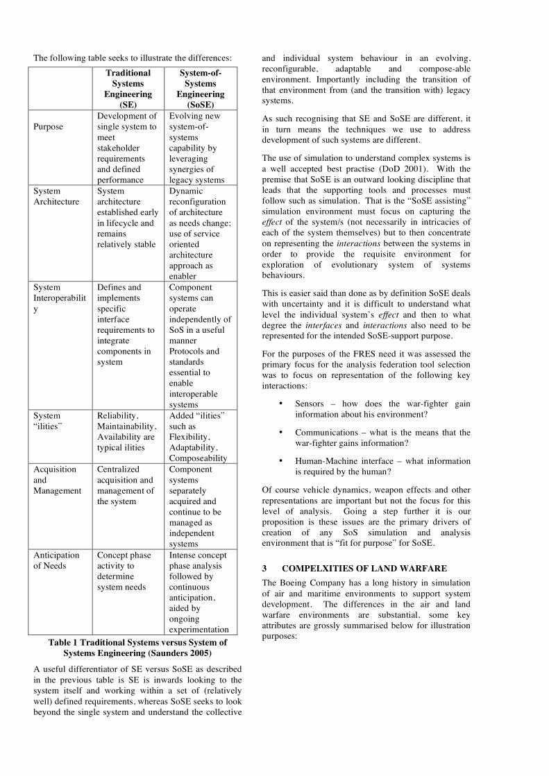
The following table seeks to illustrate the differences: Traditional
Systems Engineering
(SE)
System-of-Systems
Engineering (SoSE)
Purpose
Development of single system to meet stakeholder requirements and defined performance
Evolving new system-of-systems capability by leveraging synergies of legacy systems
System Architecture
System architecture established early in lifecycle and remains relatively stable
Dynamic reconfiguration of architecture as needs change; use of service oriented architecture approach as enabler
System Interoperability
Defines and implements specific interface requirements to integrate components in system
Component systems can operate independently of SoS in a useful manner Protocols and standards essential to enable interoperable systems
System “ilities”
Reliability, Maintainability, Availability are typical ilities
Added “ilities” such as Flexibility, Adaptability, Composeability
Acquisition and Management
Centralized acquisition and management of the system
Component systems separately acquired and continue to be managed as independent systems
Anticipation of Needs
Concept phase activity to determine system needs
Intense concept phase analysis followed by continuous anticipation, aided by ongoing experimentation
Table 1 Traditional Systems versus System of Systems Engineering (Saunders 2005)
A useful differentiator of SE versus SoSE as described in the previous table is SE is inwards looking to the system itself and working within a set of (relatively well) defined requirements, whereas SoSE seeks to look beyond the single system and understand the collective
and individual system behaviour in an evolving, reconfigurable, adaptable and compose-able environment. Importantly including the transition of that environment from (and the transition with) legacy systems.
As such recognising that SE and SoSE are different, it in turn means the techniques we use to address development of such systems are different.
The use of simulation to understand complex systems is a well accepted best practise (DoD 2001). With the premise that SoSE is an outward looking discipline that leads that the supporting tools and processes must follow such as simulation. That is the “SoSE assisting” simulation environment must focus on capturing the effect of the system/s (not necessarily in intricacies of each of the system themselves) but to then concentrate on representing the interactions between the systems in order to provide the requisite environment for exploration of evolutionary system of systems behaviours.
This is easier said than done as by definition SoSE deals with uncertainty and it is difficult to understand what level the individual system’s effect and then to what degree the interfaces and interactions also need to be represented for the intended SoSE-support purpose.
For the purposes of the FRES need it was assessed the primary focus for the analysis federation tool selection was to focus on representation of the following key interactions:
• Sensors – how does the war-fighter gain information about his environment?
• Communications – what is the means that the war-fighter gains information?
• Human-Machine interface – what information is required by the human?
Of course vehicle dynamics, weapon effects and other representations are important but not the focus for this level of analysis. Going a step further it is our proposition is these issues are the primary drivers of creation of any SoS simulation and analysis environment that is “fit for purpose” for SoSE.
3 COMPELXITIES OF LAND WARFARE The Boeing Company has a long history in simulation of air and maritime environments to support system development. The differences in the air and land warfare environments are substantial, some key attributes are grossly summarised below for illustration purposes:
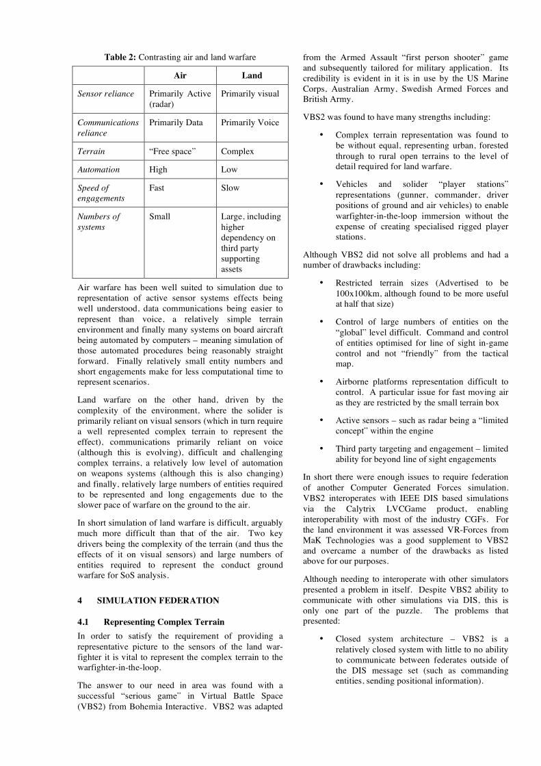
Table 2: Contrasting air and land warfare
Air Land
Sensor reliance Primarily Active (radar)
Primarily visual
Communications reliance
Primarily Data Primarily Voice
Terrain “Free space” Complex
Automation High Low
Speed of engagements
Fast Slow
Numbers of systems
Small Large, including higher dependency on third party supporting assets
Air warfare has been well suited to simulation due to representation of active sensor systems effects being well understood, data communications being easier to represent than voice, a relatively simple terrain environment and finally many systems on board aircraft being automated by computers – meaning simulation of those automated procedures being reasonably straight forward. Finally relatively small entity numbers and short engagements make for less computational time to represent scenarios.
Land warfare on the other hand, driven by the complexity of the environment, where the solider is primarily reliant on visual sensors (which in turn require a well represented complex terrain to represent the effect), communications primarily reliant on voice (although this is evolving), difficult and challenging complex terrains, a relatively low level of automation on weapons systems (although this is also changing) and finally, relatively large numbers of entities required to be represented and long engagements due to the slower pace of warfare on the ground to the air.
In short simulation of land warfare is difficult, arguably much more difficult than that of the air. Two key drivers being the complexity of the terrain (and thus the effects of it on visual sensors) and large numbers of entities required to represent the conduct ground warfare for SoS analysis.
4 SIMULATION FEDERATION
4.1 Representing Complex Terrain In order to satisfy the requirement of providing a representative picture to the sensors of the land war-fighter it is vital to represent the complex terrain to the warfighter-in-the-loop.
The answer to our need in area was found with a successful “serious game” in Virtual Battle Space (VBS2) from Bohemia Interactive. VBS2 was adapted
from the Armed Assault “first person shooter” game and subsequently tailored for military application. Its credibility is evident in it is in use by the US Marine Corps, Australian Army, Swedish Armed Forces and British Army.
VBS2 was found to have many strengths including:
• Complex terrain representation was found to be without equal, representing urban, forested through to rural open terrains to the level of detail required for land warfare.
• Vehicles and solider “player stations” representations (gunner, commander, driver positions of ground and air vehicles) to enable warfighter-in-the-loop immersion without the expense of creating specialised rigged player stations.
Although VBS2 did not solve all problems and had a number of drawbacks including:
• Restricted terrain sizes (Advertised to be 100x100km, although found to be more useful at half that size)
• Control of large numbers of entities on the “global” level difficult. Command and control of entities optimised for line of sight in-game control and not “friendly” from the tactical map.
• Airborne platforms representation difficult to control. A particular issue for fast moving air as they are restricted by the small terrain box
• Active sensors – such as radar being a “limited concept” within the engine
• Third party targeting and engagement – limited ability for beyond line of sight engagements
In short there were enough issues to require federation of another Computer Generated Forces simulation. VBS2 interoperates with IEEE DIS based simulations via the Calytrix LVCGame product, enabling interoperability with most of the industry CGFs. For the land environment it was assessed VR-Forces from MaK Technologies was a good supplement to VBS2 and overcame a number of the drawbacks as listed above for our purposes.
Although needing to interoperate with other simulators presented a problem in itself. Despite VBS2 ability to communicate with other simulations via DIS, this is only one part of the puzzle. The problems that presented:
• Closed system architecture – VBS2 is a relatively closed system with little to no ability to communicate between federates outside of the DIS message set (such as commanding entities, sending positional information).

• Terrain correlation – VBS2 strength of complex terrain representation is done in such a “revolutionary” or unorthodox (for military simulation) it makes it very difficult to correlate for a number of reasons. This issue is discussed in detail below.
4.1.1 Terrain correlation
Simulations are driven by the problem they are seeking to assist and also take a long time to be developed and accepted. As such it is not surprising that many of the warfare simulations in use today have been created or evolved from technologies and techniques over the last couple of decades, are geared towards Cold War era symmetric warfare scenarios, an example being the Fulda Gap (Faringdon 1989) on the former East German border of large armoured troop movements in open and rolling terrain between Soviet and Allied forces. As such the underlying simulation technology created to represent this “old world” has been geared towards this undulating, open and rural terrain. As dictated by the on-going Operations in Iraq and Afghanistan, the balance has shifted from a symmetric threat to focus to that of an asymmetric nature. A threat that has moved the location of the battlefield away from the open and rural to the complex terrain. That is the primary insurgent technique of force protection is via dispersion and sanctuary within complex terrain (Metz 2004), therefore in order to represent the current day fight this factor became a key driver in the technology selection process.
In traditional military focused CGF the underlying terrain engines have tended to fall into one of the two categories:
• Cell based terrain representations (such as DTED): JANUS, JTLS
• Fixed Level of Detail (LOD) polygonal terrain representations (such as OpenFlight and CTDB): ITEMS, S-Mission, VRForces, MODSAF, OneSAF
Cell based terrains fail almost completely to represent urban terrain (without a separate building/urban algorithm) due to the cell based approach not being able to represent shear faces in order to represent (the sides of ) buildings.
During the late 1990’s and early 2000’s, the simulation terrain representation evolved to a steady state of fixed level of detail (LOD) polygonal terrains with the success of OpenFlight and derived fixed LOD polygonal databases such as Compact Terrain Database (CTDB). What this enabled was (the promise of) a flexible terrain representation to represent almost any type of terrain. A specific goal of the OpenFlight format was that it was authored from the point of view that multiple simulations could read and display the terrain in a consistent way. That is the logic for generation of the terrain was kept as much in the file format itself so it could be reproduced. Many
simulations adopted such a concept of terrain representation meaning terrain correlation was achievable in that even if the file format was supported the underlying concepts were and correlation could be achieved.
VR-Forces, for example, employ a terrain representation based on a fixed LOD concept.
Enter so-called serious games such as VBS2, leveraging the “next generation” of terrain representation technology that can be summarised as various techniques of applying continuous levels of detail using parametric techniques that allow for a much more realistic looking world. Examples include the addition of procedurally generated grass and or rocks with the effects of trees swaying in the wind down to representation of leaves on trees. Whereas before such “environmental clutter” was rare and fields of barren polygonal expanses were common. This heightened detail also supported complex structures of multi-storey buildings with accompanying fixtures of doors, windows, etcetera that benefited from advanced custom clipping and collision/intersection detection routines.
A significant advantage of these next generation techniques is a much more accurate and visually pleasing representation of the complex terrain landscape from open to rural through to urban. This ability to represent complex terrain is paramount to representing the effect visual sensors in a representative way that hadn’t been achieved before (albeit without significant effort in authoring very large fixed LOD databases).
The problem of these new techniques is they shift the display logic away from the file format and into the rendering / simulation engine. What this results in is a non-standard approach to terrain representation if you wish to interoperate with other simulators. That is it is difficult to impossible to provide the same level of terrain representation, since the logic of world representation is game specific and or proprietary that other techniques such as traditional fixed LOD polygonal terrains are conceptually ill suited to achieve adequate correlation (Pajarola 2007 discusses these problems in detail).
This issue was handled (read not fully solved) by separating the types of systems represented in the federated tactical environment. The functionality boundary is illustrated below:
Table 3: Separation of federate usage by sensor and weapon system
VBS2 Other federates (VRForces etc)
Sensors Human in the loop Visual
Radar, Acoustic, CGF Visual
Weapon Systems
Line of sight Beyond line of sight

This separation by system type enabled trading on the strengths of each federate while working within the constraints, primarily due to the terrain correlation issue.
A proprietary technique worked in conjunction with Bohemia Interactive and Boeing UK enabled a method to generate DTED (elevation), ESRI shapefiles (building footprints, roads, rivers etc) and high resolution topographic maps from any VBS2 terrain. This subsequently enabled the ability to use standard terrain building tools in other federates on reverse engineered VBS2 terrains. This method enabled a good correlation between federates within the constraints of the system representations above.
It should be noted Boeing is also funding a project between Bohemia Interactive, MaK Technologies and Presagis (previously Terrex) for VBS2 and VRForces terrains to be generated in a single pipeline through TerraVista. At the time of writing the VRForces plug-in is complete with the VBS2 version to be published in the “(US) Summer release” of 2008.
4.2 Large Numbers Of Entities And Contributors The experience of transitioning simulation from air to land warfare, particularly on SoS programs such as FRES is a very large entity count and higher number of contributors to the perceived situation picture.
The large numbers of entities range from symmetric scenarios where force on force interaction requires large numbers of red and blue through to asymmetric scenarios that may not include large numbers of threat forces but large numbers of civilian population. End result is lots of entities.
The increased entity count intensifies the age old simulation issue of behaviour representation as it is rare to have enough subject matter experts available to “play” each role, artificial intelligence is key to providing the representation of the various the systems’ effect’s.
The impact of a more complex terrain (urban, building internals etc) exacerbates this problem further as the models for entity movement need to be aware of the more detailed surroundings requiring more advanced route finding techniques.
Asymmetric warfare in particular places a new emphasis on pattern of life simulation, as threats such as insurgents use techniques of blending with the civilian population to conduct their operation. Therefore representation of marketplaces, people transiting to and from places of work or worship including reaction to certain conditions is important to be represented. Noting here civilian population and combatants present different behaviour representation challenges (i.e. crowds versus squad tactics).
Both VBS2 and VRForces provide the ability to represent intelligent behaviour in computer controlled entities. Neither federate was found to excel in this area
but both were found to be adequate with a degree of operator “cajoling”. A bigger issue in this respect was using large numbers of entities external to VBS2 (release 1.18) as it was found to induce intolerable slow downs when using airborne surveillance assets such as UAVs. VBS2’s internal message passing was found to be far less intensive than DIS (via LVCGame) and as such it was found large numbers (100’s of entities) was only possible if they were represented within VBS2 with smaller numbers (10’s of entities) being represented in other federates. This technical restriction was exacerbated as VBS2 control interface was found to be restrictive for large numbers of entities. This issue was forced to be addressed by requiring highly skilled Exercise Control members (always the last choice when technology does not fit the bill).
4.3 Representing “The Situational Picture” One of the concepts under-pinning the FCS and FRES programs is “networking” of the land battlespace. A key part to this is the introduction of systems that contribute to the goal of a shared/integrated situation picture. Traditionally the land battle has had such a localised focused the main tool for communication was the voice radio and paper maps. Digitisation or networking seeks to provide the land war fighter with the same benefits of shared situation awareness that has been utilised in the air and maritime environment for a number of years albeit the first generation of such networked systems (a.k.a. battle management systems) are in operation with a number of nations Armies such as Force XXI Battle Command Brigade and Below (FBCB2) with US Army and Bowman ComBAT Infrastructure and Platform Battlefield Information System (BCIP) with British Army. The “user interface” to such systems is commonly referred to as the Battle Management System (BMS).
In order to experiment with the flow of information and how that is presented and used by the warfighter, it is often required to provide aspirational functionality beyond current functionality of fielded systems.
In order to represent this picture two proprietary federates were produced, the first a (non-Boeing) federate that represented touch screen map display to emulate the functionality of the BMS system that represented a human-in-the-loop interface including:
• APP6a/MILSTD-2525B symbology
• Blue Force Tracker/Sighting/Contact/Call for fire reports
• Graphical orders (phase lines, kill boxes etc)
• Third party engagement (Beyond Line of Sight)
The second was a Network Effects Server (NES) that implements a communications effects standard developed by Boeing Australia with Scalable Network Technologies (and now adopted by Presagis and MaK CGFs) to provide communications effects through use

of Signal and Data Interactions over a DIS or HLA RPR FOM federation. The NES implemented this standard on the FRES program and additionally interfaced with both the BMS and ASTi DIS radios to simulate voice priority to provide the effect of the network being busy during times of human speech on a given the network, slowing down the data traffic such as Blue Force Tracker.
The coupling of the experimental BMS and NES provided a representative battle management picture that was constrained by radio capabilities and network traffic such that different networking configurations and equipments could be trailed and analysed within the environment.
An additional issue with the land environment is the number of contributors to the situational picture, as such representing “the picture” through simulation becomes more of a challenge as is the experience of the authors that you rarely get enough warfighters to operate all stations for a given experiment. As such the BMS system was extended to enable the AI to enter their own reports based on sensors and detection/identification/recognition states such that certain reports would be passed to the “network” as if passed by a human. This was an important ability to represent the multitude of contributors to the land situation picture without the need of populating every station.
4.4 Analysis Of A Complex Federation The analysis of the VBS2, VRForces, BMS, ASTI voice radio and NES communication effects was conducted by the Boeing Analysis for Simulation Environment (BASE). BASE enables real time and post process visualisation of the measures of effectiveness (MOEs) in 3D, 2D, voice playback, bar/line, network, stoplight, scoreboard views.
BASE was used throughout all phases war-fighter-in-the-loop experiments was in all phases of the conduct across:
• Exercise control – real time display of success and failure criteria to enable consistent “stop exercise” determination
• Hot debrief – post experiment to provide after-action review and show real versus perceived pictures, key MOEs immediately after the runs used by both the Analysts and Command team to hot-debrief “what went right” and “what went wrong”
• Analysis – used extensively to wade through gigabytes of simulation data in order to quantatively present timelines, kill-chains, sources of success and failure through the recorded information
Figure 1: Hot debrief inside The Portal, BASE displays metric on the left and perceived picture on the middle screen
More information on the BASE tool and its flexible architecture for analysing different data sources (such as DIS, BMS and voice traffic in this federation) can be found in (Nixon 2004).
5 SOLUTION The following figures depict the resultant warfighting in complex terrain, system of systems analysis environment simulation federation: The underlying backbone was VBS2 client–server protocol and IEEE DIS version 6 with extensive use of custom Signal and SetData PDUs for the BMS and communications effects traffic.
Virtual crew
stations
Crew station
server
Voice and data
comms effects
server
Battle Management
System (BMS)
Simulation analysis
tools
Constructive
simulation model
Operational analysis
“Gods Eye ” viewer
Voice comms
units
Simulation
backbone
White Force
background
Comms delays
Blue players
Report generation
Track management
Simulation bandwidth
Health monitoring
Real time MoPs
Battle situation
Multi channel voice comms
Figure 2: Functional view of federation
BIA
VBS2 1.18 HF6
Calytrix
LVCGame 1.18
Boeing
Network Effects
Server
Battle Management
System (BMS)
DIS Monitor
MaK
VRForces 3.10
Boeing BASE
MaK Logger
ASTi
Telestra 4
IEEE
DIS v6
Entity State
Fire
Detonation
Emission
Transmitter
Signal
SetData
Entity State
Fire
Detonation
Signal
SetData
Simulation bandwidth
Health monitoring
Real time MoPs
Battle situation
Multi channel voice comms
Transmitter
SignalReceive allReceive all
Figure 3: Application view of federation
6 EXPERIMENTS
6.1 Experiment Diamondback – Utility Variant In Semi Rural Terrain
Experiment Diamondback was conduct to gain insights into requirements trades on the FRES Utility Variant vehicle “threshold” and “objective” system of system requirements (as defined in the User Requirements Document) in a focused invention operation context and their effect on force effectiveness. The two key user requirements under investigation were situation awareness and interoperability.
Figure 4: Diamondback Blue Force ORBAT
6.2 Experiment Kestrel – Formation Recce in Complex terrain
Experiment Kestrel was part of a MOD sponsored activity, within FRES Assessment Phase 2, constructed to provide insight into FRES Specialist Variant vehicles. The complete experimentation program involved Whole life Cycle costing, Force Structure trades in addition to this warfighter in the loop analysis.
Experiment Kestrel was a warfighter-in-the-loop analysis on the Formation Reconnaissance role under a medium scale power projection context, to assess the effect of changes in Situation awareness, Interoperability, Lethality within open/rural and urban terrain. The outputs were used to inform the development of the Special Variant vehicles’ User Requirements Document (URD), System Requirements Document (SRD) and FRES Concept of Use (CONUSE).
Each of the Formation Reconnaissance vehicles were created in VBS2 against the specifications in the URD and SRD. Noting that these vehicles were required to be “notional” as no systems have yet to be selected as this experiment supported FRES in the assessment phase.
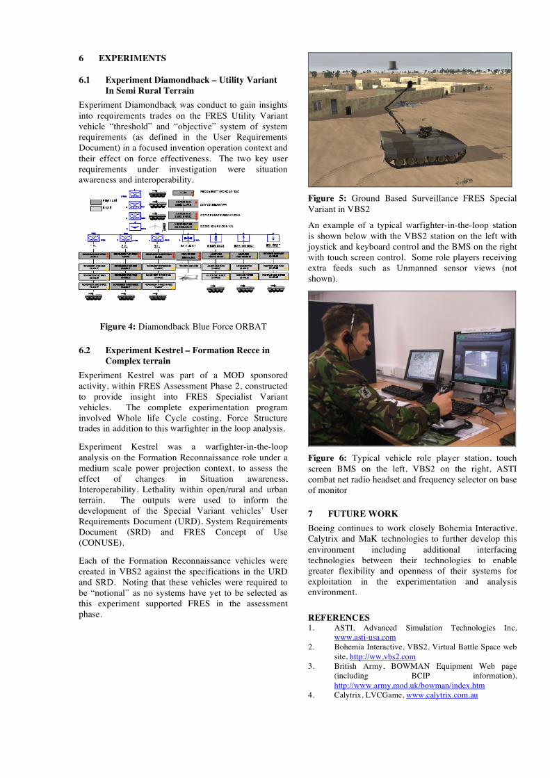
Figure 5: Ground Based Surveillance FRES Special Variant in VBS2
An example of a typical warfighter-in-the-loop station is shown below with the VBS2 station on the left with joystick and keyboard control and the BMS on the right with touch screen control. Some role players receiving extra feeds such as Unmanned sensor views (not shown).
Figure 6: Typical vehicle role player station, touch screen BMS on the left, VBS2 on the right, ASTI combat net radio headset and frequency selector on base of monitor
7 FUTURE WORK Boeing continues to work closely Bohemia Interactive, Calytrix and MaK technologies to further develop this environment including additional interfacing technologies between their technologies to enable greater flexibility and openness of their systems for exploitation in the experimentation and analysis environment.
REFERENCES 1. ASTI, Advanced Simulation Technologies Inc,
www.asti-usa.com 2. Bohemia Interactive, VBS2, Virtual Battle Space web
site, http://ww.vbs2.com 3. British Army, BOWMAN Equipment Web page
(including BCIP information), http://www.army.mod.uk/bowman/index.htm
4. Calytrix, LVCGame, www.calytrix.com.au

5. Crossley, W.A., (2004) "System of Systems: An Introduction of Purdue University Schools of Engineering's Signature Area."
6. DoD, (2001) “Systems Engineering Fundamentals”, US Department of Defence Systems Management College, Chapter 13 pp 121-126
7. Faringdon, H. (1989) “Strategic Geography: NATO, the Warsaw Pact, and the Superpowers”, Routledge, ISBN 0-415-00980-4.
8. MaK Technologies, VR-Forces web page, http://www.mak.com/products/vrforces.php
9. Metz, S. and Millen, R.A., (2004) “Insurgency and Counterinsurgency in the 21st Century: Reconceputalizing Threat and Response”, Monograph, Strategic Studies Institute, US Army.
10. Nixon, A. (2004), "A Flexible Software Architecture For Visualising Simulation Data", SimTect 2004.
11. Pajarola and Gobbetti, (2007), “Survey on Semi-Regular Multi-resolution Models for Interactive Terrain Rendering”, The Visual Computer 23(8), pp 583–605.
12. Presagis, TerraVista, http://www.presagis.com/products/content_creation/details/terra_vista/
13. US Army, FBCB2 web page, http://peoc3t.monmouth.army.mil/fbcb2/about.html
14. Sage, A.P. and C.D. Cuppan, (2001) "On the Systems Engineering and Management of Systems of Systems and Federations of Systems," Information, Knowledge, Systems Management, Vol. 2, No. 4 (2001), pp. 325-345.
15. Saunders, T. et al,(2005) “United States Air Force Scientific Advisory Board Report on System-of-Systems Engineering for Air Force Capability Development,” SAB-TR-05-04
16. Scalable Network Technologies, www.scalable-networks.com
17. Schiavone, G. A., et al (1995), “Interoperability issues for terrain databases in distributed interactive simulation”, Distributed interactive simulation systems for simulation and training in the aerospace environment; Proceedings of the Conference, Orlando. pp. 89-118. 1995
18. Schlager, J. (1956). "Systems engineering: key to modern development". IRE Transactions EM-3: pp. 64-66.