Creating Your Job File - Power Analytics · PDF file1.0 Creating a Job File ... Select the...
103
R072214 Creating Your Job File in DesignBase POWER ANALYTICS CORPORATION 16870 West Bernardo Drive, Suite 330 San Diego, CA 92127 U.S.A. © Copyright 2014 All Rights Reserved
Transcript of Creating Your Job File - Power Analytics · PDF file1.0 Creating a Job File ... Select the...

R072214
Creating Your Job File in DesignBase
POWER ANALYTICS CORPORATION 16870 West Bernardo Drive, Suite 330
San Diego, CA 92127 U.S.A.
© Copyright 2014
All Rights Reserved

Paladin DesignBase
i
Table of Contents Page
1.0 Creating a Job File – Subject Network ............................................................... 3
2.0 Creating the New Drawing File ............................................................................ 4 2.1 Setting the Master File Editor .................................................................................................................. 7 2.2 Auto-Snap Control Management ............................................................................................................ 13 2.3 Building the Single Line Diagram .......................................................................................................... 14 2.4 The Bus Counter Function ..................................................................................................................... 26 2.5 The Generator Short Circuit Model ....................................................................................................... 27 2.6 Checking for Errors in the Network ....................................................................................................... 28 2.7 Adding Operating Scenarios to the Network .......................................................................................... 29 2.8 The Data Structure Analyzer .................................................................................................................. 34
3.0 Text Back Annotation ........................................................................................ 35
4.0 Color Back Annotation ...................................................................................... 36
5.0 Copying and Pasting Network Components .................................................... 37
6.0 Locking and Unlocking a Page ......................................................................... 39
7.0 The “Make-Straight” Function .......................................................................... 40
8.0 Managing DesignBase Catalogs ....................................................................... 41 8.1 Opening & Closing DesignBase Catalogs ............................................................................................. 42 8.2 Creating & Saving Catalogs .................................................................................................................. 43 8.3 Assigning Icons to Catalogs ................................................................................................................... 44 8.4 The “Complex Components” Catalog ................................................................................................... 45
9.0 Hyperlinks to the External Files, Applications and the World Wide Web ...... 47
10.0 Multiple Page Files with Hyperlinks .................................................................. 49
11.0 Creating DesignBase Projects / Multiple Hyperlinked Drawing Files ............ 54
12.0 Locating Symbols in a Project .......................................................................... 58
13.0 The Project Manager .......................................................................................... 60

Paladin DesignBase
ii
14.0 The Database / Text Editor ................................................................................ 61
15.0 MCC & Panel Auto-Links ................................................................................... 62
16.0 Panel & MCC Schedules .................................................................................... 64
17.0 Automatic Transfer Switches ............................................................................ 70
18.0 Project Version Control ..................................................................................... 71
19.0 Security Administration Commands ................................................................ 74 19.1 User Maintenance .................................................................................................................................. 75 19.2 Access Control Maintenance .................................................................................................................. 77 19.3 Access to Protected Files ....................................................................................................................... 79 19.4 Changing Protection Settings ................................................................................................................. 80 19.5 Revision Control..................................................................................................................................... 81
20.0 Creating and Managing Project Libraries ........................................................ 85
21.0 Creating UPS Models ......................................................................................... 91 21.1 Using the Complex Components UPS Model ......................................................................................... 95
22.0 Creating Rectifier and Inverter Models ............................................................. 96 22.1 Modeling Rectifiers ................................................................................................................................ 96 22.2 Modeling Inverters ................................................................................................................................. 99 22.3 Using the Complex Component Inverter and Rectifier Models ............................................................ 102

Paladin DesignBase
3
1.0 Creating a Job File – Subject Network This document will illustrate how to create, modify and customize a single line diagram using DesignBase 5.0 graphical user interface. The system shown below will be used as an example. As the actual step by step process is explained, the user will be simultaneously introduced to a critical application called the “Master File Editor”. This tool allows the user to control base-parameters and settings that are critical during the modeling and analytical process of the job file.

Paladin DesignBase
4
2.0 Creating the New Drawing File
Step 1. Select “New Drawing File”.
Step 2. Select the “EDSA” tab and then select the “Electrical One-Line AC 3Phase.axt” template. Click “OK”.
Step 3. Name the file as indicated, and select “Open”.

Paladin DesignBase
5
Step 5. Click “ok “after filling the master file General information.
Step 4. If required, assign a password and select “OK”.

Paladin DesignBase
6
Step 6. The blank ANSI B sheet is shown here with border and default title block.
ANSI Element Catalog Section.
ANSI Bus Cat.
ANSI Branch Cat. Hyperlink Catalog. Callout Catalog.

Paladin DesignBase
7
2.1 Setting the Master File Editor
Step 4. Specify all the required base kVA, units and temperature parameters for the study.
Step 1. Select this icon to invoke the “Master File Editor”.
Step 2. Select the “General” tab, and complete the information pertaining to the job file under study.
Step 3. Select the “Network Settings” tab.

Paladin DesignBase
8
Step 7. Select the “Visibility” tab.
Step 8. Again leave all visibility fields un-selected. Select the standard for the symbols to be used (ANSI or IEC).
Step 5. Select the “AC Visibility” tab.
Step 6. Based on the studies that are required, select the specific fields that need to be displayed in the component editor-screens. In this case leave all fields de-selected. Also, specify the electrical units to be used.

Paladin DesignBase
9
Step 9. Select the “Name Management” tab.
Step 12. Define the operating scenarios as required. A detailed explanation of this function is available in further sections of this document.
Step 11. Select the “Scenarios” tab.
Step 9. Select the “Name Management” tab.
Step 12. Define the operating scenarios as required. A detailed explanation of this function is available in further sections of this document.
Step 11. Select the “Scenarios” tab.
Step 10. Specify how to construct the name of buses being copied and pasted from existing ones. In this case we have chosen to continue incrementing by 1.

Paladin DesignBase
10
Step 18. Select the “More Branch Defaults” tab.
Step 13. Select the “Bus Defaults” tab.
Step 15. Select the “AC Branch Defaults” tab.
Step 14. Define the default values of voltage, size and SCKVA for source and motor buses.
Step 16. Define the default code and size for feeders and transformers.

Paladin DesignBase
11
Step 18. Specify default codes/sizes for the remainder of the branch types as shown here.
Step 17. Select the “3P Branch Defaults” tab.
Step 20. If conducting a “Voltage Profile” load flow analysis, specify the number of time periods to be simulated in conjunction with their respective time duration.
Step 19. Select the “Time Periods” tab.
Paladin DesignBase
12
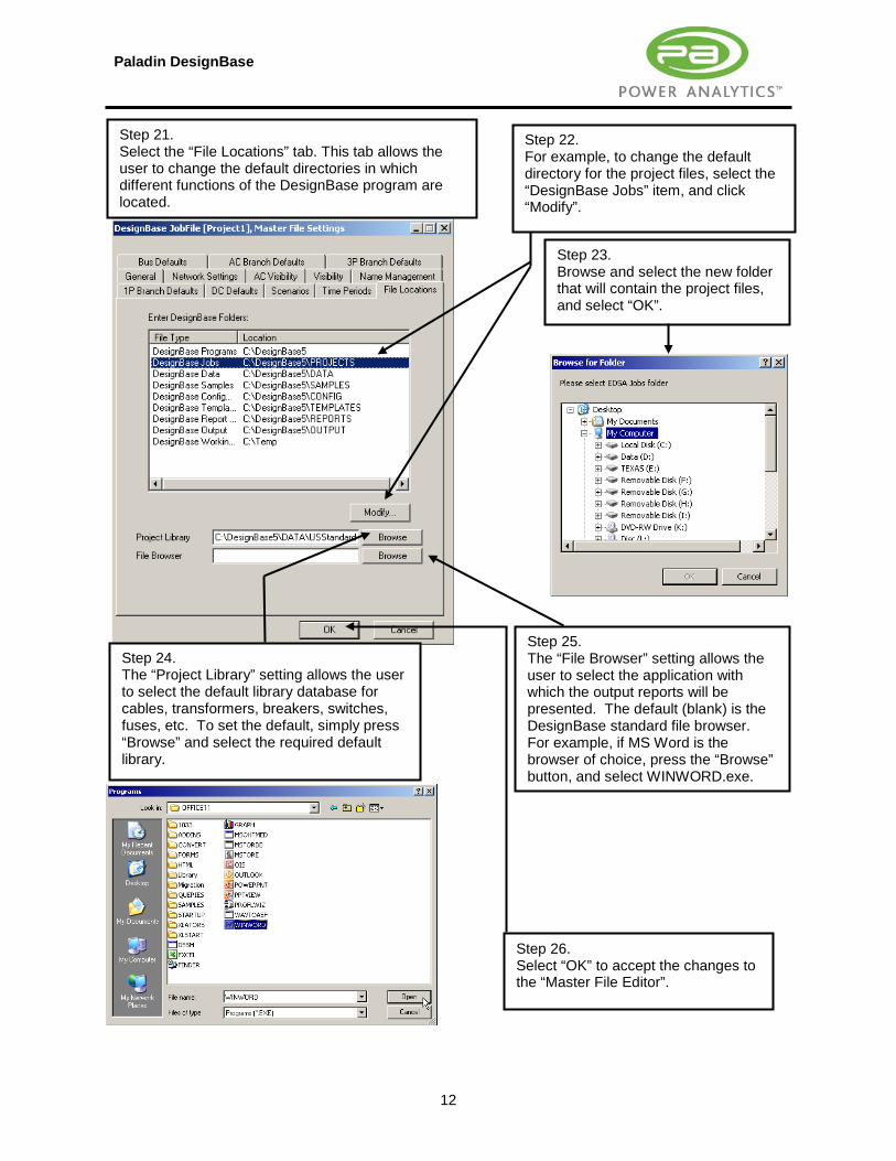
Step 21. Select the “File Locations” tab. This tab allows the user to change the default directories in which different functions of the DesignBase program are located.
Step 23. Browse and select the new folder that will contain the project files, and select “OK”.
Step 26. Select “OK” to accept the changes to the “Master File Editor”.
Step 22. For example, to change the default directory for the project files, select the “DesignBase Jobs” item, and click “Modify”.
Step 25. The “File Browser” setting allows the user to select the application with which the output reports will be presented. The default (blank) is the DesignBase standard file browser. For example, if MS Word is the browser of choice, press the “Browse” button, and select WINWORD.exe.
Step 24. The “Project Library” setting allows the user to select the default library database for cables, transformers, breakers, switches, fuses, etc. To set the default, simply press “Browse” and select the required default library.

Paladin DesignBase
13
2.2 Auto-Snap Control Management
Step 1. Select “Tools>AutoSnap”.
Step 2. The “AutoSnap” feature controls the way in which busses and branches connect to each other. Up to 10 different snap modes are available, depending on the user’s requirements. These modes are shown here.
Step 3. Since DesignBase is equipped with smart plug & socket technology, the basic and recommended snap modes are illustrated here. Press “OK” to accept.

Paladin DesignBase
14
2.3 Building the Single Line Diagram
Step 1. From the “ansibus” catalog, select the Utility Bus symbol, by holding the left mouse button down and dragging it over to the desired location.
Step 2. Once in place, release the mouse button.
Back Annotation insertion point socket. This socket can be dragged and placed anywhere.
Back Annotation as defined in the “Master File Editor”.

Paladin DesignBase
15
Step 3. Double click on the utility symbol and enter the Bus name, basic Description, Short Circuit and Load Flow information as shown here.

Paladin DesignBase
16
“From-End” smart plug. Step 4. Select the “ansibra” catalog.
Step 5. Select the “ANSI Fuse 1” symbol and drag it over to the desired location. For now, place it as indicated without connecting it to the utility bus”.
Back Annotation insertion plug.
“To-End” smart plug.

Paladin DesignBase
17
Step 6. Hold and drag the fuse over to the utility bus. Make sure that the “From-End” of the branch (from plug) meets the desired connection point on the Bus (socket).
Step 7. Once the socket turns blue in color and the message “Connect to Socket” appears, the connection has been successfully achieved. Release the mouse button to complete the operation.
Once the fuse is connected to the live bus, it will turn black indicating that it has been energized.

Paladin DesignBase
18
Step 8. Double click on the fuse symbol to edit its Branch name and electrical data.
Step 9. Click on the “Library” pick list to access the fuse database.
Step 10. Select the required ABB fuse from the library.

Paladin DesignBase
19
Step 12. Verify the basic short circuit information for the fuse.
Step 11. Decline the offer to insert the Curve at this point.
Paladin DesignBase
20
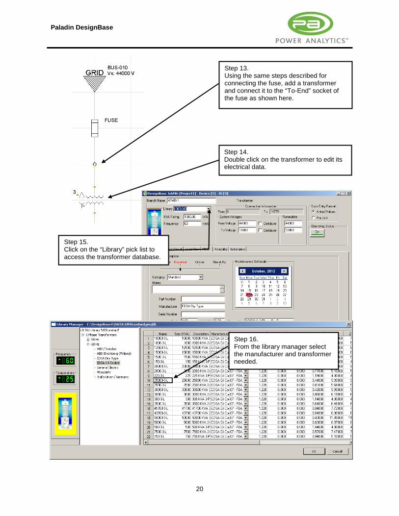
Step 13. Using the same steps described for connecting the fuse, add a transformer and connect it to the “To-End” socket of the fuse as shown here.
Step 14. Double click on the transformer to edit its electrical data.
Step 15. Click on the “Library” pick list to access the transformer database.
Step 16. From the library manager select the manufacturer and transformer needed.

Paladin DesignBase
21
Step 19. Select the primary and secondary winding configurations.
Step 20. Specify cooling type, tap settings, and impedance adjustment factors as required.
Step 18. Verify/modify the impedance information.
Step 17. Specify primary and secondary system/nameplate voltages. Click on the to voltage Distribute box.

Paladin DesignBase
22
Step 21. Following the same procedures illustrated above, add a 150 Amp breaker as shown here.
Step 22. From the “ansibus” catalog, drag and drop the “Busbar” symbol over to this position.
Step 23. Prior to adding branches to a Bus Bar, adjust its length to accommodate as many branches as required. To adjust the length of a Bus Bar, simply select it then click and drag the end sockets lengthwise as shown here. When the desired length is reached, release the mouse button.

Paladin DesignBase
23
Step 24. To add the branch breakers, drag the required breaker symbols from the “ansibra” catalog and connect them at the desired position on the Bus Bar. Once the “Connect” message appears, release the mouse button to drop the symbol in that position.

Paladin DesignBase
24
Step 25. Add a No. 4 AWG feeder from the “ansibra” catalog.
Step 27. Select the required feeder from the library. Press “OK”.
Step 26. Double click on the feeder, and select the “Library” pick-list.
Step 28. Complete the Cable/Line Data editor as shown.

Paladin DesignBase
25
Step 29. Add the 1250 HP Induction motor.
Step 30. Double click on the motor, and select the “Library” pick-list.
Step 31. Select the required motor from the library. Press “OK”.
Step 32. Complete the Short Circuit and Load Flow editors as shown here.
Paladin DesignBase
26
2.4 The Bus Counter Function
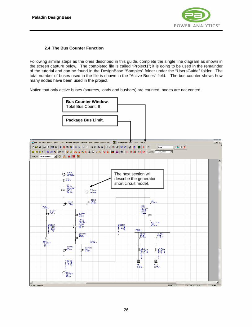
Following similar steps as the ones described in this guide, complete the single line diagram as shown in the screen capture below. The completed file is called “Project1”; it is going to be used in the remainder of the tutorial and can be found in the DesignBase “Samples” folder under the “UsersGuide” folder. The total number of buses used in the file is shown in the “Active Buses” field. The bus counter shows how many nodes have been used in the project. Notice that only active buses (sources, loads and busbars) are counted; nodes are not conted.
The next section will describe the generator short circuit model.
Package Bus Limit.
Bus Counter Window. Total Bus Count: 9

Paladin DesignBase
27
2.5 The Generator Short Circuit Model
The impedances required by the editor are explained below and are entered as a percentage of the generator’s base voltage and kVA. The X/R ratio can be calculated from the generator time constant and armature resistance information if provided. This calculation is based on equation 1. If this information is not available, the user can select “Estimate X/R ratio” and the program will add a value based on accepted IEEE standard curves. %X”dV Rated-voltage (saturated) direct-axis sub-transient reactance. It is used for first-cycle and
interrupting time calculations. %X’dV Rated-voltage (saturated) direct-axis transient reactance. It is used for time delayed currents in
relay applications. Xd Rated current unsaturated direct-axis steady state reactance. %X”2V Rated-voltage negative sequence reactance. It is used to calculate the X/R ratio and for
unbalance short circuit calculations. %X0 Zero sequence reactance. It is used in unbalanced short-circuit calculation, when dealing with
grounded generators. Ta3 Rated-voltage generator armature time constant in seconds. It is used to calculate the X/R ratio.
In some cases, the armature resistance aR may be given instead. %Ra Armature resistance. The X/R ratio is determined from the following equations:
2vEFF a3
a3
X XR 2 f T2 f T R
= ⇒ = ⋅ π ⋅ ⋅⋅ π ⋅ ⋅
(Equation No.1)

Paladin DesignBase
28
2.6 Checking for Errors in the Network
Once the network has been completed, click on the “Error Checking” icon. This will scan the database and point out any obvious modeling and connectivity errors.
Correct any errors as required and press “Done” to exit.

Paladin DesignBase
29
2.7 Adding Operating Scenarios to the Network Let’s assume that there are two scenarios under which the network modeled can operate. These two scenarios will be called “Normal Operation” and “Emergency Operation”. The screen capture shown below, indicates the status of the network components that will be affected by the operating scenarios.
Normal: ON Emergency: OFF
Normal: CLOSED Emergency: OPEN Normal: OFF
Emergency: ON
Normal: OPEN Emergency: CLOSED
Normal: CLOSED Emergency: OPEN
Step 1. Click on “Master File Editor”.

Paladin DesignBase
30
Step 2. Type “Normal Operation” here under scenario 1, and press the tab key to update the list.
Step 3. Select “New” to add the next scenario.
Step 4. Enter the second scenario number and name as indicated here. Press “OK”.
Step 5. Select scenario 1 as the “Active” scenario.

Paladin DesignBase
31
Step 6. Double click on the utility bus to access its editor.
Step 7. Click the "Status" icon.
Step 8. Define the status of the utility source as indicated and click “OK”.

Paladin DesignBase
32
Step 10. Apply the reverse states for generator and its circuit breakers.
Step 9. Repeat the steps 6-8 on fuse and circuit breaker.

Paladin DesignBase
33
Step 11. This pick list toggles between the two operating scenarios.

Paladin DesignBase
34
2.8 The Data Structure Analyzer Data Structure Analyzer examines consistency of your database and compares the database to your drawing file.
Step 1. To check for and to correct errors in your file, select the “Data Structure Analyzer” icon.
Step 2. If Devices are found in your database but not in your drawing select the “Remove Devices from database that aren’t in Drawing” button. Otherwise click “ok”.

Paladin DesignBase
35
3.0 Text Back Annotation
Step 1. Select the text “Back Annotation” tool.
Step 3. From the “Bus Input Data” and the “Branch Input Data” tabs, select the items highlighted by the circles.
Step 2. Select the Auto-Refresh box to always refresh annotation on the drawing.
Step 4. Select the preferred font type and color. Select “On” and click “OK” to return to the single line diagram. Refer to page 1 of this tutorial for the fully back annotated network.

Paladin DesignBase
36
4.0 Color Back Annotation
Step 1. Select the color “Back Annotation” tool.
The final product is shown here.
Step 2. Turn the color Back Annotation on by selecting the “On” button.
Step 3. Select the category by which the color annotation will be applied. In this example, select “Voltage Levels”.
Step 4. Modify the color settings as required and click “OK” to update.

Paladin DesignBase
37
5.0 Copying and Pasting Network Components
Step 2. Click the “Copy” command icon.
Step 3. Click the “Paste” command icon.
Step 1. Using the mouse, “fence-in” (select) the element(s) to be copied.

Paladin DesignBase
38
Also, Ctrl + C and Ctrl + V can be applied.
Step 5. Ensure that the “from” end of the breaker has been successfully connected to the bus bar. Verify that the “Connect to Geometry” message appears.
Step 4. Once the selection has been pasted, click on it and drag it over to the desired location.

Paladin DesignBase
39
6.0 Locking and Unlocking a Page Locking the page helps avoid accidental movement and/or deletion of network symbols. When selected, the user can double click on any component in order to access its editor, without the risk of altering its graphical characteristics by mistake or otherwise. Unlocking restores full graphical editing capabilities.
Page-Lock Function. Page-Unlock Function.
Paladin DesignBase
40
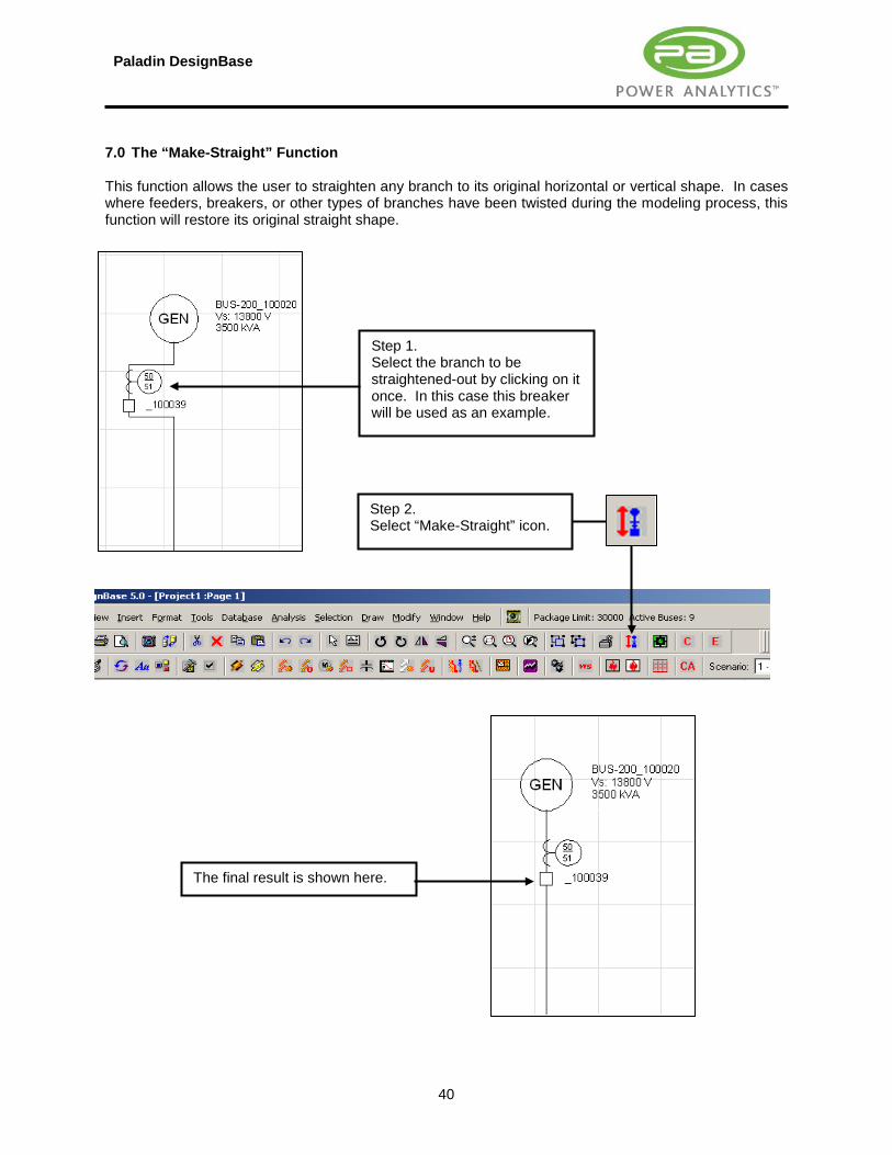
7.0 The “Make-Straight” Function This function allows the user to straighten any branch to its original horizontal or vertical shape. In cases where feeders, breakers, or other types of branches have been twisted during the modeling process, this function will restore its original straight shape.
Step 1. Select the branch to be straightened-out by clicking on it once. In this case this breaker will be used as an example.
Step 2. Select “Make-Straight” icon.
The final result is shown here.

Paladin DesignBase
41
8.0 Managing DesignBase Catalogs
To toggle the Catalog Manager in and out of sight, select “View / Content Explorer” or simply toggle the F8 key on your keyboard.
Close Catalog
New Catalog
Open Catalog
Save Catalog As
Catalogs can be managed using the commands shown here.

Paladin DesignBase
42
8.1 Opening & Closing DesignBase Catalogs
Step 1. Select “Open Catalog”.
Step 2. Select the “DesignBase/Actrix/Solutions/EDSA” folder to access all the available DesignBase catalogs. Once in the EDSA folder, select the “dc.axc” to open the DC tools catalog, and press “Open”. Step 3.
The “DC Tools” catalog is shown here, ready to be used.
Step 5. Select “Close Catalog”.
Step 4. To choose a catalog, select the catalog by clicking the appropriate tab. In this example select the “DC Tools” tab.

Paladin DesignBase
43
8.2 Creating & Saving Catalogs
Step 3. Populate the new Catalog with your own devices, by simply selecting them and dragging & dropping them into this space.
Step 2. Verify that a blank Catalog is added to the Manager.
Step 1. Select “New Catalog”.
Step 4. To save the new catalog, select the catalog’s tab and press the “Save Catalog As” icon.
Step 5. Assign a name and save the new catalog in the desired folder as indicated (DesignBase4/Actrix/Solutions/EDSA). Click “Save”.

Paladin DesignBase
44
8.3 Assigning Icons to Catalogs
Step 1. Right-Click on the Catalog’s tab to be modified.
Step 2. Select “Change Icon…”.
Step 5. Select “OK”.
Step 3. From the “Change Icon” dialog box, browse to locate the desired icon. In this case, select the “From File” option as shown here.
Step 4. Select this icon.
Step 6. The new icon is shown here. More icons can be found under C:\DesignBase4\Actrix\Solutions\EDSA

Paladin DesignBase
45
8.4 The “Complex Components” Catalog Let’s assume that we wish to create a network symbol consisting of multiple interconnected devices (busses & branches). Such a symbol can be a substation block that may be used on a regular basis. This section will illustrate how to accomplish this task, such that this new symbol can be made available from a catalog menu.
Step 1. Let’s assume that we wish to create a complex component out of the low voltage substation shown here.
Step 2. Open the “Complex Components” catalog by clicking on this icon.
Step 3. Verify that the “Complex Components” catalog has opened as shown here. Step 4.
Fence in the components from which a symbol will be created. In this case, select the entire substation as indicated here.

Paladin DesignBase
46
IMPORTANT NOTE Complex symbols such as the one shown in the preceding example, will retain connectivity (both graphical and database) only when they are stored in the “Complex Components” catalog. Storing a complex symbol into any other catalog will not work.
Step 5. Drag and drop your selection into the “Complex Components” catalog space.

Paladin DesignBase
47
9.0 Hyperlinks to the External Files, Applications and the World Wide Web DesignBase supports two types of hyperlinks. The first type allows the user to tie a network or a section of it to an external application, file, or to a specific internet site. This first type will be explained in this section. The second type of hyperlinks, allows the user to tie pages within a drawing file or within a project. This facilitates the navigation from one section of a single line diagram over to another electrically interconnected section that is located in a different page. This second type of hyperlinks will be explained in sections 10 and 11 of this manual. In this example, the file will be hyperlinked to an Excel spreadsheet file. The same procedure can be used to hyperlink to any MS Windows executable file. To access a web site on the Internet, select “URL’s” in step 5, and enter the web address.
Step 3. Double click on the hyperlink symbol to program it.
Step 2. From the “Hyperlinks” catalog, select any of the self-contained targets and drag it over to the desired section of the drawing.
Step 1. In this exercise, the transformer will be hyperlinked to its maintenance log file, which is kept in a Microsoft Excel format under C:\DesignBase5\Samples\UsersGuide. To begin, select the object (in this case the transformer) to which the hyperlink will be assigned.
Step 4. Select “Yes”.

Paladin DesignBase
48
Step 5. Select “Browse/Files”.
Step 6. Locate the file of interest, select it and click “Open”.
Step 7. Select “OK”.
Step 8. Double click on the “Hyperlink” icon to access the linked Excel file.

Paladin DesignBase
49
10.0 Multiple Page Files with Hyperlinks This section will explain, how to spread single line diagram over multiple pages while maintaining the database connectivity. The example will be based on the original Project1.axd as shown in the single line diagram below. In this case, the 2.4/0.48 kV transformer and its respective 480 V substation will be placed on a separate page.
Page No.1 Page No.2

Paladin DesignBase
50
Step 1. Create a new page, by clicking on this icon.
Step 2. Name the new page. For this example, type “Page 2”.
Step 3. Once the new blank page is added, it will immediately appear in the active pane. Return to “Page 1” by selecting it from the pick-list, as indicated here.

Paladin DesignBase
51
Step 4. Fence in the desire part of the network at Page 1. Step 5. Cut the selected part of the network. Step 6. Switch to the Page 2 and paste the network.
Paladin DesignBase
52
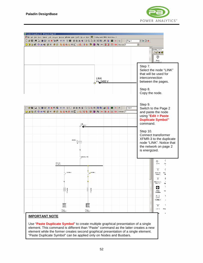
Step 7. Select the node “LINK” that will be used for interconnection between the pages. Step 8. Copy the node. Step 9. Switch to the Page 2 and paste the node using “Edit > Paste Duplicate Symbol” command. Step 10. Connect transformer XFMR-3 to the duplicate node “LINK”. Notice that the network on page 2 is energized.
IMPORTANT NOTE Use “Paste Duplicate Symbol” to create multiple graphical presentation of a single element. This command is different than “Paste” command as the latter creates a new element while the former creates second graphical presentation of a single element. “Paste Duplicate Symbol” can be applied only on Nodes and Busbars.

Paladin DesignBase
53
Step 11. Insert a hyperlink on Page 2 and connect it to node “LINK”. Step 12. Hyperlink the “LINK” to Page 1 as shown here. Step 13. Insert a hyperlink on Page 1 and connect it to node “LINK”. Step 14. Hyperlink the “LINK” to Page 2 as shown here. Step 15. Double-click on one hyperlink will open the other page and zoom on the duplicate element.

Paladin DesignBase
54
11.0 Creating DesignBase Projects / Multiple Hyperlinked Drawing Files A project may consist of a single or multiple electrically interconnected drawings. A project can be started as a single drawing file to which additional ones are added as the project progresses. When multiple drawings are electrically interconnected to each other, all the electrical data is added to a common database. This database will bear the name of the original project (usually the first drawing being created). Opening an individual drawing file that is part of a multiple drawing project will open the entire database but only that specific drawing file. On the other hand, opening the project file will open the entire database along with the drawing that is created first (the main project drawing). This section will explain how to spread a project over multiple files while maintaining the database connectivity. The example will be based on the original Project1.axd as shown in the single line diagram below. In this case, the 2.4/0.48 kV transformer and its respective 480 V substation will be placed on a separate file.
File: Project1.axd File: Project2.axd

Paladin DesignBase
55
Step 1. Let’s open the drawing file “Project1.axd”.
Step 2. Select “File > Add a New Drawing File to Project”.
Step 3. Name the new drawing as shown below. Make sure that the new drawing being added is in the same folder as the entire project.

Paladin DesignBase
56
A new drawing will open.
Step 4. Use “Window > Arrange All” if you want to view both drawings simultaneously.

Paladin DesignBase
57
Repeat the steps 4-15 from the previous section to create a network shown below.
IMPORTANT NOTE DesignBase allows use of both: multiple pages and multiple drawings. User is encouraged to use multiple drawings instead of multiple pages. Our Protective Device Coordination (PDC) software creates PDC studies as additional pages. Novice users often confuse multiple pages with PDC studies, hence the recommendation to use multiple drawings.

Paladin DesignBase
58
12.0 Locating Symbols in a Project
Step 1. Let's locate branch CB-MOT-2 which is a 250 A breaker on the BUS-90. First select the “Find” icon”.
Step 2. From the pick-lists, select CB-MOT-2 branch.

Paladin DesignBase
59
Step 3. The program finds the requested branch in its respective drawing.

Paladin DesignBase
60
13.0 The Project Manager
Master Database
This section shows a list of the drawings in the project including the pages that are part of each drawing. Click on any page to access it.
Click here to invoke the “Project Manager”.
Network components. Click once to locate the symbol in the drawing, or double click to access its editor.

Paladin DesignBase
61
14.0 The Database / Text Editor
Step 1. Select the “Text Editor” icon. Step 2.
The “Text Editor” is another way to edit the database components without using the graphic interface. The different functionalities include sorting, editing, navigating and deleting components.

Paladin DesignBase
62
15.0 MCC & Panel Auto-Links
Panel & MCC Link icons are capable of tying sections of the network across two pages automatically. When used they will create a new page, add a hyperlink and provide an MCC or Panel bus bar for adding loads.
Step 1. To add an MCC Link, click, drag and place the MCC Link symbol over to the desired location.
Step 2. This symbol represents the hyperlink between page 1 and page 2. To go to page 2, simply double click on this symbol.

Paladin DesignBase
63
Step 3. Verify that this page (Page 2) has been automatically created.
Step 4. This bus bar represents the newly added MCC. Proceed to attach all the required loads to this bus bar.
Step 5. This symbol represents the hyperlink between page 2 and page 1. To go back to page 1, simply double click on this symbol.

Paladin DesignBase
64
16.0 Panel & MCC Schedules DesignBase allows the user to enter load schedules directly from the load editor. The loads entered in this fashion can be composed of purely static loads, motor loads, or a combination of both. The reader must interpret the term static load as a load that does not contribute to short circuit currents (Lights, heaters, etc.). The key issue here is that when grouping different types of loads in the load schedule application, the user must specify what category the intended schedule falls under. From the Load Flow point of view, it is quite simple since all types of loads must be considered as demand on the system. This means that from on the Load Flow side of the load editor they will always be considered as loads. This is clearly shown in the figure below.
Load Schedule
Static Loads Only Mixed Load
Static Loads Motor Loads
Impact on Load Flow
Impact on Short Circuit

Paladin DesignBase
65
From the Short Circuit point of view, however, careful consideration must be given to the classification, since the short circuit contribution of different types of motor loads is calculated according to specifically different guidelines. The following table will guide the user on how to define the Short Circuit section of the load editor when entering different types of combinations. The next exercise will be based on the following example: System Voltage: 480 V Load Type: MCC Schedule Loads Connected: 1. Motor 1 150 HP 2. Heating Block 150 kW As it can be appreciated from this example, there are a total of 2 loads that must be considered from the Load Flow point of view, while only 1 of them will impact the Short Circuit calculations.
Step 1. Add one MCC symbol in the project.
Step 2. From the Short Circuit tab, select “MCC/Schedule”.

Paladin DesignBase
66
Step 3. From the pick-list on line 1, select “Induction Motor”.
Step 4. From the library manager, select a 460 V / 150 HP motor as shown here.

Paladin DesignBase
67
Step 6. From the pick list, select "Breaker" as the protective device.
Step 8. Select "Feeder". Select a suitable feeder for the motor from the cable library.
Step 7. Select this cell.
Step 9. Enter the "Length" of the feeder and the breakers "Amp" setting (Prot Amps).
Step 5. Select “Prot Dev/Cable” section.
Step 10. Select “Usage” section.
Paladin DesignBase
68
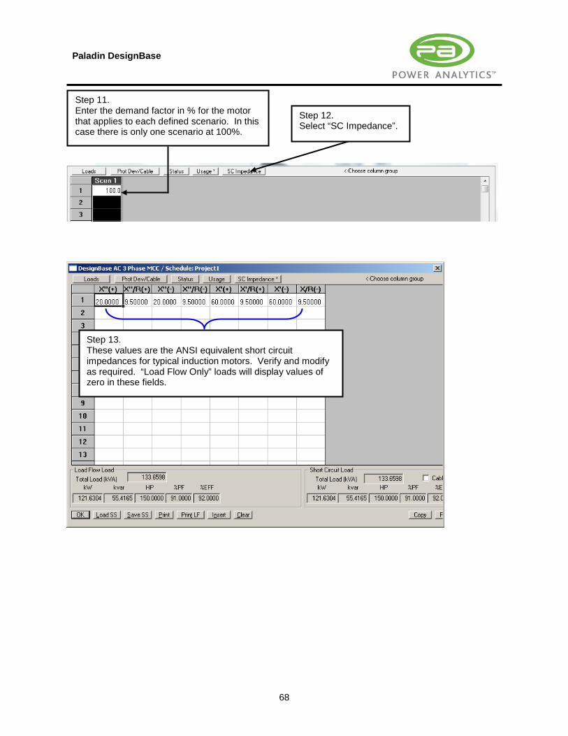
Step 11. Enter the demand factor in % for the motor that applies to each defined scenario. In this case there is only one scenario at 100%.
Step 12. Select “SC Impedance”.
Step 13. These values are the ANSI equivalent short circuit impedances for typical induction motors. Verify and modify as required. “Load Flow Only” loads will display values of zero in these fields.

Paladin DesignBase
69
Step 14. Following a similar procedure, enter the data for the “Heating Block” as shown here.
The running totals for Load Flow and Short Circuit are shown here.

Paladin DesignBase
70
17.0 Automatic Transfer Switches
Step 1. Open the file “Project1.axd”. In this example, these switches will be interlocked such that only one of them can be closed at any given time. This will serve to transfer the load of the network from the Grid over to the Generator and vice-versa.
Step 2. Double click on the generator output breaker CB-HV-2.
Step 3. Select “ATS”.
Step 4. Select the "Associated Branch." Click “OK”
Paladin DesignBase
71
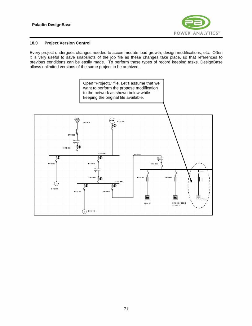
18.0 Project Version Control Every project undergoes changes needed to accommodate load growth, design modifications, etc. Often it is very useful to save snapshots of the job file as these changes take place, so that references to previous conditions can be easily made. To perform these types of record keeping tasks, DesignBase allows unlimited versions of the same project to be archived.
Open ”Project1” file. Let’s assume that we want to perform the propose modification to the network as shown below while keeping the original file available.

Paladin DesignBase
72
Step 3. Add password protection as required and press “OK”.
Step 1. Select the “Snapshot” tool.
Step 2. Enter a name for the original file and select a folder in which to archive it. Select “OK”.

Paladin DesignBase
73
Step 5. To access a previous version of the file (while working on the most recent one) select the “Roll-Back” tool.
Steps 1 to 3 can be repeated every time a new historical record is needed prior to a revision being made.
Step 4. Make the necessary changes to the file and save your work.
Step 6. From the list, select the archived version of the project to view, and select “OK”.

Paladin DesignBase
74
19.0 Security Administration Commands Topics presented in this section concern advanced administrative privileges that can be assigned to multiple users of the same project files. We advise the reader to skip this section unless he is specifically interested in this topic.
The security administration commands are accessed from the “Tools” menu as shown here.
“User Maintenance” Allows the administrator to add system users.
“Access Control Maintenance” Allows the job manager to add users to a specific job file. Users must be listed in the “User Maintenance” list.
“Change Protection” Enables or disables of the file password protection feature.

Paladin DesignBase
75
19.1 User Maintenance
Step 2. Enter the Administrator’s “User ID” and “Password” as entered during the installation process. Select “OK”.
The administrator can either modify settings for existing users by selecting them from the “User ID” pick-list, or add a new user by selecting the “New User” command. Let’s add a new user.
Step 1. Select “User Maintenance”.

Paladin DesignBase
76
Step 3. In this dialog box, the administrator can list all the users, change their access password, change access privileges and also add/delete users. To add a new user, select “New User”.
Step 4. Type the new user's “User ID”, “Full Name” and “Password”. Then define the user type as “User”. Select “OK” to complete to add the user.
Step 5. Select “Save” and then select “Done”.

Paladin DesignBase
77
19.2 Access Control Maintenance After user accounts are created, users can assign access levels to specific job files for other specific users. When a user creates a new job file (either with File – New or File – Save As), that user is considered the manager of that new job file. To be allowed to assign access levels to job files, the user must be a validated user. Thus, the user must enter a password before that user can define access levels for a new job file. Obviously this means the user account must be created by an administrator before the user can assign access privileges. User accounts are created as explained in section 19.1. The available privilege levels for job file access are: Manager, Writer, Reader, None. Any user can be assigned any access level to a job file. The creator of the job file is designated as a Manager. Managers can specify other managers, or give lower levels of privilege to other users. • Managers have full access to the job file, including changing access levels for other users. • Writers can read, write, modify, and delete data in the job file. • Readers can only read data from the job file. • None means that the user cannot access the job file. Privilege levels may be specified for as many users as the job file manager desires. These privileges specify what access is permitted for the users, thus the list of privileges is called the Access Control list. Step 1.
When a new job file is created, the user has the opportunity to specify what access controls are to be used for the job file. The user is presented with this dialog box. The user must then specify an existing “User ID” and the respective “Password”. It is important to keep in mind that this MAY NOT be the only password for the job-file. This is the password for the user managing the job-file. When done, select “OK”.

Paladin DesignBase
78
Step 2. To add a new user to this job-file, select “Access Control Maintenance” from the “Security” menu.
Step 3. Select “Add”.
Step 4. Type the “User ID” and assign the access privilege applicable to the currently open job-file. Select “Writer” and press “OK”. The user being added is “edsauser” who was previously added to the user access list in step 19.1.
Step 5. To complete the operation, select “Save” and then select “Done”.

Paladin DesignBase
79
19.3 Access to Protected Files
Step 1. Select the file to be opened.
The user must fill in the “User ID” And “Password” fields, as well as indicate what level of access is requested. The user has the option of choosing an access level below the one assigned to his/her “User ID” for that job file. For example, a user with “Writer” access may select “Reader” access when opening the job file. After selecting the desired access level press “Continue”.

Paladin DesignBase
80
19.4 Changing Protection Settings
Step 2. Enable or disable the password protection as required and press “OK”.
Step 1. Select “Change Protection” from the “Security” menu to enable or disable file password protection.

Paladin DesignBase
81
19.5 Revision Control The file used for this example, has two users; one is the job manager (ID: “manager” / Password: “manager”) and the other is a user/writer (ID: “user / Password: “user”). The example will show how the user/writer can make changes to the file and then submit them to the job manager for approval.
Step 1. Log in as “edsauser” and select “Writer” as the access level allowed.
Step 2. Double click on this transformer, and modify its wiring configuration from “Delta-Wye Grounded” to Delta-Delta.
Step 3. Invoke the “Master File Editor”

Paladin DesignBase
82
Once the user has modified the file, the manager can verify and approve the changes.
Step 4. Select “Revision History”.
Step 5. Enter a title for the report that is descriptive of the modifications performed. Press “OK”. Save the file and close it.
Step 6. Log in as “manager” and select “Manager” as the access level allowed.

Paladin DesignBase
83
Step 9. Highlight the report and select “Report” to review any modifications made by the users.
Step 7. Invoke the “Master File Editor”
Step 8. Select “Revision History”.
Step 10. Reports can be Approved or Unapproved by selecting the respective commands. Press “OK” to exit. A list of all the modifications done to the job file will be shown in the output report.

Paladin DesignBase
84
Step 11. To approve changes on an equipment by equipment basis, select the device in question and double click on it to access its editor.
Step 12. To approve, select “Approve”. Press “OK” to exit.

Paladin DesignBase
85
20.0 Creating and Managing Project Libraries
Step 1. From the “Database” menu, select “Project Libraries”.
The DesignBase "Library Manager" will appear as

Paladin DesignBase
86
Step 1. Define the units (metric or US) for the library to be created, by selecting “Change Unit System”.
Step 2. Select the required unit system and press “OK”.
Step 3. Select the display frequency and temperature by clicking on the “Change Display” icon.
Step 4. Select the required temperature & frequency and press “OK”.
Step 5. Select “Add New Item” to begin adding devices to the library.
Step 6. Select the type of device to be added. Select a “3 Phase” “Feeder”, as shown here and press “OK”.

Paladin DesignBase
87
Step 7. Enter a “Library Name” for the feeder.
Step 8. In the “Description” tab, enter the feeder’s “Manufacturer” name and a suitable “Description”.
Step 9. In the “Cable/Line Data” tab, enter the impedance values for the feeder based on 1000 feet of length.
Step 11. Enter the ampacity rating of the feeder at the different temperatures specified in the editor.
Step 10. Select the cable “Material”.

Paladin DesignBase
88
Step 13. To save the new project library file, select “Save As Library”.
Following the same steps shown here, the user can continue to build the library by adding devices such as transformers, breakers, fuses, line reactors, etc.
Step 12. The new feeder has been successfully added to the project database, and it is displayed in a categorized tree format as shown here.
Step 14. Type a name for the new library, and press “Save”.

Paladin DesignBase
89
Step 17. To assign the new library file as a default for a project, select the “Master File Editor”.
Step 15. The user also has the option of importing data from other existing libraries. To do this, open the library you want to import to, select the “Import” command.
Step 16. Select the library to import, and press “Open”.
IMPORTANT NOTE The action requested in Step 16 may last longer than expected. As there are thousands of items in that US library, it takes time to process them all. You may want to skip step 16, or have patience until it is over. Usual workflow is to create smaller library and import it in the big one.
Paladin DesignBase
90
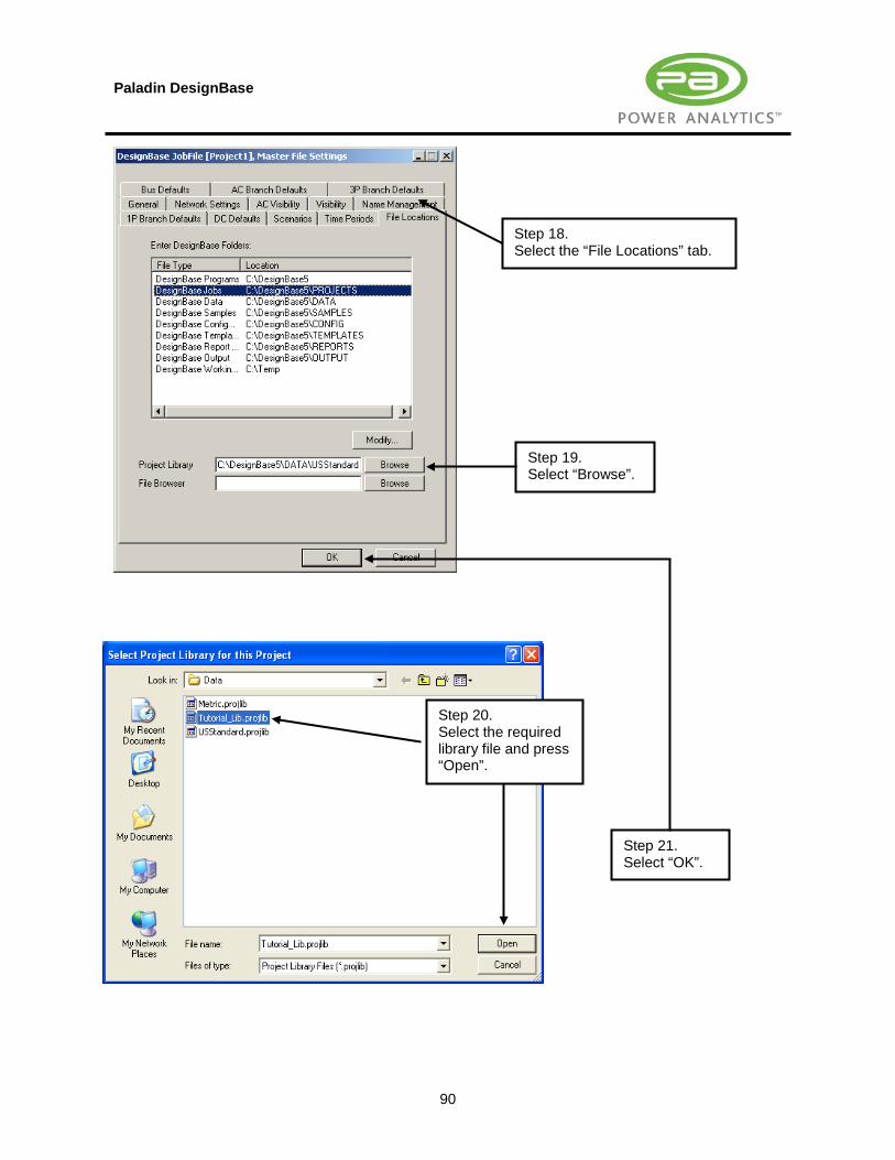
Step 18. Select the “File Locations” tab.
Step 19. Select “Browse”.
Step 21. Select “OK”.
Step 20. Select the required library file and press “Open”.

Paladin DesignBase
91
21.0 Creating UPS Models An Uninterruptible Power Supply (UPS) connected to an AC network, essentially represents an AC load (burden) on that AC system. On the other hand, the output of the UPS acts as a power supply to the loads that it is backing-up and as such it is a source of power. For a model to be accurate in every way, the loads connected to the output of the UPS must be automatically accounted for as part of the total load that the UPS input presents to the AC system feeding it. DesignBase provides three different models capable of handling any situation. These three models are: Method 1: The user enters the total kW and kVAR load represented by the UPS. This total accounts for: ● UPS Nominal Rating (kW + kVAR) ● The critical load supported by the UPS (kW + kVAR) ● The UPS recharging load (kW + kVAR) ● The UPS losses (kW + kVAR) Method 2: The user enters the load of the UPS broken down into its individual components: ● UPS Nominal Rating (kW + kVAR) ● The critical load supported by the UPS (kW + kVAR) ● The UPS recharging load (kW + kVAR) ● The UPS losses (kW + kVAR) Method 3: The user enters the following data: ● UPS Nominal Rating (kW + kVAR) ● The UPS recharging load (kW + kVAR) ● The UPS losses (kW + kVAR) The load data pertaining to the supported critical load, is automatically calculated (through a Load Flow) by the program based on the UPS power source output model. The following sections will illustrate how to model UPS’s using the DesignBase editor.

Paladin DesignBase
92
UPS Short Circuit output model.
UPS Load Flow input model.
UPS Short Circuit output model.
Step 1. To illustrate how the UPS model works, open the file “Upsexp.axd” found under: “C:\DesignBase5\Samples\AdvPF\Upsexp.exd”
Step 3. To edit the input of the UPS, double click on bus “5”.
Step 2. The UPS model is composed of two symbols as shown here.

Paladin DesignBase
93
Step 4b. Select “Method 2” to break down the details of the load represented by the UPS. Enter the data as required.
Step 4a. Select “Method 1” to model the total load represented by the UPS, and proceed to enter the data as required.
Step 4c. Select “Method 3” to link the load connected to the output of the UPS to the input total load.
Step 4e. Enter the rest of the data as required.
Step 4d. From the pick-list, select the node that represents the UPS output source model. Select bus 20.

Paladin DesignBase
94
Loads are automatically transferred to the input.
Step 5. Double click on bus 20, to edit the output of the UPS.
Step 6. From the Short Circuit tab, select the short circuit model to be used and enter the required information. Press “OK”.

Paladin DesignBase
95
21.1 Using the Complex Components UPS Model
Step 3. Set up the UPS model as required, by following the procedure shown in section 21.0.
Step 1. The “Complex Components” catalog contains a pre-modeled symbol for the input/output of the. To use it, simply invoke the “Complex Components” catalog, by clicking on this icon.
Step 2. Drag, drop, and connect the UPS symbol into the desired position.

Paladin DesignBase
96
22.0 Creating Rectifier and Inverter Models Rectifiers take AC power and convert it into DC power. Inverters take DC power and turn it into AC power. DesignBase allows these types of converters to be modeled into job files defined as hybrid files. This means that a job file of this sort is set up as an AC-DC network. Both types of converters have the capability of translating their respective output loads over to their total input load for the purposes of AC/DC load flow calculations. Conversely, each of the outputs acts as a power source for the loads being supported. The following section will illustrate how to interconnect the AC and DC nodes in order to effectively model rectifiers and inverters. The file that will be used in this example can be found in the Design Base 5.0, “Samples” folder. The specific path for the file is: C:\DesignBase5\Samples\ACDCLF\AC_DC_AC1A.AXD.
22.1 Modeling Rectifiers
Step 1. Open the file “ACDCLF\AC_DC_AC1A.AXD”.
Step 2. Identify the “Rectifier” system.

Paladin DesignBase
97
Step 3. To interlock the output DC bus (Rectifier) with the input AC bus, both the AC and DC buses must have the same ID.
This is modeled as an AC bus.
This is modeled as a Rectifier.

Paladin DesignBase
98
Step 7. Assign the same bus ID used in step 4 (“Rectifier”).
Step 8 Define the Short Circuit and Load Flow characteristics of the rectifier.
Step 4. Double click on the AC Rectifier symbol. Step 5.
Assign a bus ID. In this case use “Rectifier”.
Step 6. Double click on the DC Rectifier symbol.

Paladin DesignBase
99
22.2 Modeling Inverters
Step 1. Open the file “ACDCLF\AC_DC_AC1A.AXD”.
Step 2. Identify the “Inverter” system.

Paladin DesignBase
100
Step 3. To interlock the output AC bus with the input DC bus (Inverter), both the AC and DC buses must have the same ID.
This is modeled as an AC Bus.
This is modeled as an Inverter.

Paladin DesignBase
101
Step 5. Define the Short Circuit and Load Flow characteristics of the inverter.
Step 3. Double click on the Inverter.
Step 4. Assign a bus ID. In this case use “Inverter”.
Step 6. Double click on the AC Bus.
Step 7. Assign the same bus ID used in step 4 (“Inverter”).

Paladin DesignBase
102
22.3 Using the Complex Component Inverter and Rectifier Models
Step 3. Set up the Rectifier and/or Inverter models as required, by following the procedures shown in section 24.1 & 24.2.
Step 1. The “Complex Components” catalog contains pre-modeled symbols for the inverters and rectifiers as explained in sections 24.1 and 24.2. To use it, simply invoke the “Complex Components” catalog, by clicking on this icon.
Step 2. Drag, drop, and connect the required symbol into the desired position.