© creatas High-Wire Act - IEEE Power & Energy...
12
18 IEEE power & energy magazine november/december 2012 1540-7977/12/$31.00©2012IEEE Digital Object Identifier 10.1109/MPE.2012.2213011 Date of publication: 18 October 2012 By Ram Adapa High-Wire Act © CREATAS
Transcript of © creatas High-Wire Act - IEEE Power & Energy...

18 ieee power & energy magazine november/december 20121540-7977/12/$31.00©2012IEEE
Digital Object Identifier 10.1109/MPE.2012.2213011
Date of publication: 18 October 2012
By Ram Adapa
High-Wire Act© creatas

november/december 2012 ieee power & energy magazine 19
D
HVdc Technology: The State of the Art
DevelopeD to meet a combination of technical anD economic considerations, high-voltage dc (hvdc) was launched in 1954 with the first commercial trans-mission link between the island of Gotland and the Swedish mainland. Since then, hvdc tech-nology has advanced dramatically, and more than 100 hvdc transmission systems have been installed around the world. though each individual transmission project will claim its own set of reasons justifying the choice of hvdc, the most common arguments favoring hvdc include the following:
✔ lower overall investment cost ✔ the potential for long-distance transmission ✔ lower losses, because hvdc typically comprises active power flow only and thus causes 20% lower losses than hvac lines, which comprise active and reactive power flow
✔ the potential for asynchronous interconnection—for example, it allows the connection of 50-hz and 60-hz networks
✔ higher system controllability, with at least one hvdc link embedded in an ac grid—in the deregulated environment, the controllability feature is particularly useful where control of energy trading is needed
✔ less expensive circuit breakers and simpler bus-bar arrangements in switchgear, because hvdc links do not increase the short-circuit currents, as converters ensure that the current added never exceeds a preset value
✔ increased stability and improvements in power quality ✔ enhanced environmental solutions.
further, many countries around the world (e.g., china, india, South africa, and brazil) are building or considering building hvdc systems at voltage levels of !800 kv and above, creating a need for additional research to develop various components to operate at these ultrahigh-voltage (Uhv) levels.
another area for hvdc application that is growing steadily around the world is the inte-gration of renewable resources such as wind into the main transmission grid. hvdc over-
head lines for onshore wind integration projects and hvdc cables for offshore projects have been proposed in north america and europe for both technical and economic reasons. Dc grids with multiple voltage-source converters (vScs) are one of the techni-cal solutions for pooling offshore wind energy and transmitting it to load centers located far away onshore.
the smart grid is the most popular buzzword in the electric utility industry nowadays. Utilities around the world are under-taking smart grid projects. though early smart grid projects have been focusing on the distribution level, the trend is toward smart
transmission-level controllers as well. it is foreseen that many hvdc and flexible ac trans-mission system (factS) controllers will be installed in the transmission and distribution networks to realize the “smart” transmission and distribution network. according to a recent report from pike Research, one of the most important high-growth sectors in the utility mar-ket is hvdc transmission. the firm forecasts that annual global investment in hvdc will increase by 44% over the next five years, rising from US$8.4 billion in 2010 to US$12.1 billion in 2015. though most of the growth is foreseen in asian countries like china and india, it is also anticipated that a significant increase in hvdc applications will take place in europe and north america due to renewable resource integration.
traditionally, hvdc technology uses line-commutated converters (lccs) based on thyris-tors, though the new vSc technology using insulated gate bipolar transistors (iGbts) has both turn-on and turn-off capability and is being considered for new hvdc projects. the power rat-ings of vSc-based hvdc converters are growing and are in the range of 1,000 mW per pole. though vSc-based hvdc converters are the technology of choice for future dc grids, there
20 ieee power & energy magazine november/december 2012
figure 1. Principle of operation of the multilevel converter.
+Ud/2
-Ud/2
Vac
Vac
t
Um
figure 2. Modular multilevel converter topology.
SM
SM
SM
SM
SM
SM
SM
SM
SM
SM
SM
SM
SM
SM
SM
SM
SM
SM
Ud
IGBT1 D1
D2IGBT2
Half Bridge Phase Unit
ConverterArm
IGBT1
IGBT2
IGBT3
IGBT4D2
D1
D4
D3
Full Bridge

november/december 2012 ieee power & energy magazine 21
are technical challenges that need to be resolved to make dc grids feasible. one of the new technology requirements for dc grids is the dc circuit breaker, which is being developed by hvdc manufacturers.
this article describes the state of the art in hvdc technology and discusses the new applications of hvdc and new converter developments, such as modular multilevel vSc converters.
VSC Technology Until 1997, the only available hvdc technology was based on thyristor valves; it is also referred to as LCC, HVdc clas-sic, or conventional HVdc. lcc technology is mature and is now available at ratings of up to !800 kv and 6,000 mW per bipolar line (for overhead transmission), and it has reached a very high degree of reliability. although lcc technol-ogy still serves the transmission industry well, it has a few drawbacks.
✔ it consumes reactive power, which needs to be sup-plied through shunt capacitor banks or other reactive support devices.
✔ it is sensitive to the strength of the ac system, particu-larly at the inverter.
✔ it generates ac and dc harmonics, which require the use of ac and dc filters.
✔ it is susceptible to commutation failures (at the inverter).
in 1997, vScs were introduced to the hvdc transmis-sion market in the experimental hellsjon project at !10 kv and 3 mW. vScs utilize power electronic valves with both turn-on and turn-off capability, usually based on iGbts. although relatively new to the power transmission industry, vSc technology was used in industrial applications for sev-eral years prior to 1991. Since its introduction in 1997, vSc ratings for both voltage and power have increased steadily; ratings of up to !320 kv (500 kv in monopolar applications) and 1,000 mW are currently available.
the first generations of vSc developed were based on two- or three-level vScs using pulsewidth modula-tion (pWm) techniques with high switching frequencies (1–2 khz). this resulted in large converter losses that could reach as high as 2–3%. existing two-level or three-level converters using pWm have to switch the full dc voltage in large steps. this causes high harmonic distortion and high transient stresses, resulting in high-frequency (hf) noise.
Recently, the industry moved to a new generation of mod-ular multilevel vScs, with the first commercial project (trans bay cable in the United States, at 400 mW and !200 kv) going into commercial operation in 2010. the modular multi-level converter provides certain technical advantages, mainly lower losses (between 0.9% and 1%) and lower or no filtering requirements. the technology has evolved in recent years, and it is commercially available from a number of manufacturers.
Trans Bay Cable Project
Novato
San Rafael
Richmond
Oakland
San LeandroPleasanton
400 MW88 km
Livermore
400 MW Active Power±170 MVAr Reactive Power~88 km Submarine Cable±200 kV dc230 kV/138 kV, 60 Hz
Concord
PittsburgAntioch
Vallejo
Martinez
California
Potrero Hill
Daly City
SanFrancisco
=~
=
=~
=
figure 3. Trans Bay Cable’s VSC-based dc link.

22 ieee power & energy magazine november/december 2012
figure 4. The Yunnan–Guangdong 800-kV UHV dc link in China.
China Southern Power Grid
800 kV dc - 1418 km–5000 MW
Commercial OperationPole 1 - December 2009Pole 2 - June 2010
Reduction in CO2 : 32,9 m tons p.a.By Using Hydro Energy & HVDCtransmission vs. Local Power Supply with Energy Mix
figure 5. The North East–Agra UHV dc link in India.
Naggu
Qamdo
Lhasa
T I B E T
INDIA
Delhi
Ludhiana
Saharanpur
HIMALAYA
NEPALKathmandu
Lucknow
Jaipur
Kota
Udaipur Murwara
Allahabad
Agra
Xixabangma Peak 8012 m
Alipurduar
Biswanath Chariali
Bhopal
Vadodara
Pune
Sholapur
Aurangabad
Latur
Malegaon
Kurnool
Hyderabad
Warangal
Vishakhapatnam
Brahmapur
Bhubaneshwar
ORISSANagpur
Jamshedpur
Varanasi
PatnaShilong
Raigang
Ranchi
Sittwe
Monywa
Guwahati
Chittagong
YangonRangoon
NelloreBellary
Bangalore
Panaji
ChennaiMadras
DhakaDacca
BANGLADESH
november/december 2012 ieee power & energy magazine 23
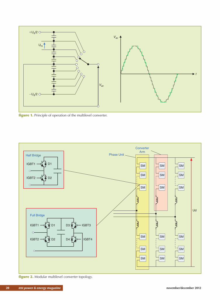
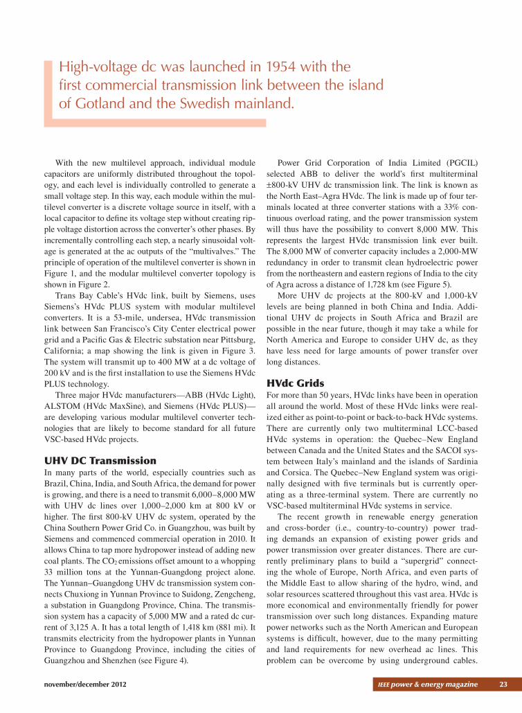
With the new multilevel approach, individual module capacitors are uniformly distributed throughout the topol-ogy, and each level is individually controlled to generate a small voltage step. in this way, each module within the mul-tilevel converter is a discrete voltage source in itself, with a local capacitor to define its voltage step without creating rip-ple voltage distortion across the converter’s other phases. by incrementally controlling each step, a nearly sinusoidal volt-age is generated at the ac outputs of the “multivalves.” the principle of operation of the multilevel converter is shown in figure 1, and the modular multilevel converter topology is shown in figure 2.
trans bay cable’s hvdc link, built by Siemens, uses Siemens’s hvdc plUS system with modular multilevel converters. it is a 53-mile, undersea, hvdc transmission link between San francisco’s city center electrical power grid and a pacific Gas & electric substation near pittsburg, california; a map showing the link is given in figure 3. the system will transmit up to 400 mW at a dc voltage of 200 kv and is the first installation to use the Siemens hvdc plUS technology.
three major hvdc manufacturers—abb (hvdc light), alStom (hvdc maxSine), and Siemens (hvdc plUS)—are developing various modular multilevel converter tech-nologies that are likely to become standard for all future vSc-based hvdc projects.
UHV DC Transmissionin many parts of the world, especially countries such as brazil, china, india, and South africa, the demand for power is growing, and there is a need to transmit 6,000–8,000 mW with Uhv dc lines over 1,000–2,000 km at 800 kv or higher. the first 800-kv Uhv dc system, operated by the china Southern power Grid co. in Guangzhou, was built by Siemens and commenced commercial operation in 2010. it allows china to tap more hydropower instead of adding new coal plants. the co2 emissions offset amount to a whopping 33 million tons at the Yunnan-Guangdong project alone. the Yunnan–Guangdong Uhv dc transmission system con-nects chuxiong in Yunnan province to Suidong, Zengcheng, a substation in Guangdong province, china. the transmis-sion system has a capacity of 5,000 mW and a rated dc cur-rent of 3,125 a. it has a total length of 1,418 km (881 mi). it transmits electricity from the hydropower plants in Yunnan province to Guangdong province, including the cities of Guangzhou and Shenzhen (see figure 4).
power Grid corporation of india limited (pGcil) selected abb to deliver the world’s first multiterminal !800-kv Uhv dc transmission link. the link is known as the north east–agra hvdc. the link is made up of four ter-minals located at three converter stations with a 33% con-tinuous overload rating, and the power transmission system will thus have the possibility to convert 8,000 mW. this represents the largest hvdc transmission link ever built. the 8,000 mW of converter capacity includes a 2,000-mW redundancy in order to transmit clean hydroelectric power from the northeastern and eastern regions of india to the city of agra across a distance of 1,728 km (see figure 5).
more Uhv dc projects at the 800-kv and 1,000-kv levels are being planned in both china and india. addi-tional Uhv dc projects in South africa and brazil are possible in the near future, though it may take a while for north america and europe to consider Uhv dc, as they have less need for large amounts of power transfer over long distances.
HVdc Gridsfor more than 50 years, hvdc links have been in operation all around the world. most of these hvdc links were real-ized either as point-to-point or back-to-back hvdc systems. there are currently only two multiterminal lcc-based hvdc systems in operation: the Quebec–new england between canada and the United States and the Sacoi sys-tem between italy’s mainland and the islands of Sardinia and corsica. the Quebec–new england system was origi-nally designed with five terminals but is currently oper-ating as a three-terminal system. there are currently no vSc-based multiterminal hvdc systems in service.
the recent growth in renewable energy generation and cross-border (i.e., country-to-country) power trad-ing demands an expansion of existing power grids and power transmission over greater distances. there are cur-rently preliminary plans to build a “supergrid” connect-ing the whole of europe, north africa, and even parts of the middle east to allow sharing of the hydro, wind, and solar resources scattered throughout this vast area. hvdc is more economical and environmentally friendly for power transmission over such long distances. expanding mature power networks such as the north american and european systems is difficult, however, due to the many permitting and land requirements for new overhead ac lines. this problem can be overcome by using underground cables.
High-voltage dc was launched in 1954 with the first commercial transmission link between the island of Gotland and the Swedish mainland.

24 ieee power & energy magazine november/december 2012
but underground ac cables can only be used for short dis-tances due to their charging current requirements. Where long distances, high power levels, and underground cables are required, hvdc transmission is the viable option. in addition, the integration of offshore wind farms will utilize both submarine cables offshore and possibly underground cables onshore. With the growing number of hvdc links in nearby areas, it is natural to think of connecting them together to provide further flexibility in power transmis-sion. When two or more of these hvdc links are connected together, the result will be a dc grid.
in a two-terminal hvdc system utilizing an lcc, power reversal is achieved by reversing the dc voltage polarity; such polarity reversal is not an issue in the two-terminal hvdc topology and can be performed on a regular basis. but in a multiterminal hvdc system, the change of power direction at any one terminal can only be achieved by utiliz-ing reversing switchgear; this is the technique that has been adopted so far. Such switchgear can run at either high speed or slow speed, depending on how fast the power reversal is intended to be. it also means that each converter must be insulated for the full dc voltage at both sides of the converter. Some have suggested using converters with antiparallel thyristors, but this technology has not been adopted in any existing schemes. in an lcc-based multiterminal system, a commutation failure at any terminal will bring down the dc
voltage in the entire system to nearly zero, and almost all the dc current will flow into the converter that failed commuta-tion. the recovery from the commutation failure is therefore time-sensitive and depends greatly on the ac system strength at the faulted terminal. commutation failures are not rare and occur for any ac fault that causes a sudden phase shift or a voltage drop of more than about 0.15 p.u. at an inverter terminal. it is generally not acceptable for a dc grid to fully stop power transmission from all terminals for a consider-able time (hundreds of milliseconds) for any ac fault near any inverter.
Realizing a dc grid utilizing lccs is therefore not practi-cally feasible because of the problems with:
✔ power reversal ✔ the impa ance of the ac system strength at each termi-nal for the complete system recovery.
in principle, realizing dc grids utilizing lcc is not an easy task. the subject of dc grids has therefore not been actively pursued in the past, although multiterminal hvdc with up to four terminals is certainly a reality.
With the introduction of the vSc, the topic of dc grids has been revived. this is the result of the following factors:
✔ change of power direction is achieved by reversing current direction for any terminal.
✔ there are no commutation failures. ✔ ac system strength at each terminal does not affect the performance of the terminal.
vSc technology is therefore the preferred option for con-nection in a multiterminal dc grid configuration.
Technical Challengesalthough a dc grid utilizing vScs is conceptually achiev-able, there are a number of technical challenges that need to be addressed. for a true dc grid to work efficiently, certain aspects must undergo further research and development:
✔ sophisticated power flow and dc voltage control strategy ✔ protection coordination ✔ fast tripping of faulted parts (branches) without affect-ing the rest of the grid
✔ backup protections (isolation failure) ✔ communication requirements and operation during communication failure
✔ supply of load after isolation of a dc grid segment ✔ future integration of other terminals from various vendors
✔ standard dc voltage levels.figure 6. (a) Topology 1 and (b) topology 2.
(b)
(a)
dc Node
ac Node
dc Line
The use of HVdc for future transmission is growing faster than ever for economic and technical reasons.

november/december 2012 ieee power & energy magazine 25
HVdc Grid Configurationsfigure 6 shows two potential topologies for connecting multiple ac nodes using hvdc links. in the topology shown in figure 6(a), the ac nodes are linked to each other using point-to-point hvdc schemes. in this topology, there are two converters for each dc line, and power flow in each line can be fully controlled. further, each link can be rated to oper-ate at a different dc voltage, and the existing dc links can therefore be easily incorporated into the grid. the common dc system protection philosophy can be used to protect each scheme separately. Since each line has converter stations at both ends, the number of converters is twice the number of links, which leads to a large number of converters. building a dc grid using such a topology will therefore be very costly. in addition, because of the large number of converters, the losses are high.
the second topology, shown in figure 6(b), represents a meshed dc system. in this case, the entire hvdc transmis-sion system is interconnected. because of these interconnec-tions, this topology has redundancy in power flow paths, i.e., power can flow along an alternate path if one of the links is out of service. the number of converters in this topology is less than the number of links. the capital cost of converters and the converter losses are both much lower than in the previous topology, and therefore this topology is more suit-able for a dc grid.
a dc grid can be built to operate in monopole or bipole mode. a monopolar system can be built with ground return, metallic return, or as a symmetrical monopole.
Protection Requirementsthe critical technical difficulty in creating a dc grid is its protection. in general, the main obstacles to overcome in providing protection to a dc system, as compared with an ac system, are as follows:
✔ a dc fault is supplied by all ac systems connected to the dc grid through the antiparallel diodes in the vScs.
✔ the fault current is limited by the highly reactive line impedance in case of an ac system. the line imped-ance is very low in case of a dc line, however; hence the rate of rise for the dc fault current is very high. therefore, a dc protection scheme has only a few mil-liseconds to come into action.
✔ Due to the low impedance of the dc grid, a short cir-cuit will cause significant voltage drop in almost the
entire network and would virtually halt the power flow in the whole dc grid. the fault therefore must be cleared very quickly to maintain the stability of the underlying ac network.
✔ Since there are no zero crossings of the dc current, breaking a dc current is significantly more difficult.
✔ as power electronic switches cannot withstand high fault currents, the converters need to be pro-tected for relatively lower fault currents as compared with ac.
in a point-to-point vSc hvdc scheme, in the event of a dc fault, the fault current is interrupted by tripping the hvdc system by the ac side breakers. this will disconnect the hvdc link from the ac terminals, which will interrupt the dc power flow and bring the dc voltage down to zero. for systems with overhead dc lines, the majority of dc faults are temporary, and the system can resume operation after clearing the fault. this process takes several hundred ms. for underground cable systems, however, the majority of dc faults are permanent, and therefore the hvdc system does not restart after the fault. in the case of a meshed dc grid, interrupting the fault current by opening the ac breakers is not a viable option, as this will cause the complete interrup-tion of the dc power flow in the entire dc grid for every dc fault. there is, therefore, a need for a reliable way of sepa-rating the faulted element from the grid in the shortest pos-sible time and with minimal impact on the power flow in the healthy parts of the dc grid.
in sum, a dc grid protection system must have almost all the features of an ac protection system, but a dc grid pro-tection system should operate and clear faults more quickly than an ac system (within a few milliseconds, and preferably within 5 ms).
DC Breaker Conceptsas highlighted previously, one of the biggest obstacles to overcome in order to make dc grids a reality is the develop-ment of a fast dc breaker capable of rapidly interrupting high dc fault currents. it is anticipated that the interruption time will need to be 5 ms or less to protect the converter equipment from damage. at present, high-speed dc switches are used in point-to point lcc hvdc systems for a variety of switching functions. Such switches are, fundamentally, single-phase ac breakers modified to withstand dc voltages across the open contacts and (in some applications) equipped with a passive-commutation circuit. the switches are used as neutral bus
The relationship of cable length to the choice of an ac or dc transmission voltage is strongly influenced by cable capacitance.

26 ieee power & energy magazine november/december 2012
switches (nbSs), neutral bus ground switches (nbGSs), metallic return transfer breakers (mRtbs), high-speed bypass switches (hSbSs) for the blocking and deblocking of series converters, and isolating switches. in most of these applications, however, the converter controls play an impor-tant role, which is not the case with a vSc hvdc system.
interrupters to break dc short-circuit currents are not often used, and their maximum interrupting currents are not that high. for example, the typical dc breaker demonstrated as reported in the literature has a maximum interrupting current of 8 ka at 250 kv, which is only 1.6 times the rated current. further, the breaking times of these breakers are on the order of tens of milliseconds (e.g., 35 ms)—not good enough for vSc-based hvdc systems.
Solid-State Circuit Breakersfigure 7 shows the schematic diagram of a solid-state circuit breaker. because the current flows through the solid-state switches during normal operation, the on-state losses are critical in this topology. thyristor-type devices like gate-commutated thyristors (Gcts) may therefore be preferred over iGbts in this application, due to their lower conduction losses. the operation of this circuit breaker is fairly straight-forward. Until a fault is detected, Gcts are conducting and the dc current flows through them; when a fault is detected, they are turned off. once the Gcts are turned off, the voltage across them increases rapidly until the varistor knee point is reached and it starts to conduct. as in the case of a hybrid circuit breaker, the knee point voltage of the varistor is set above the grid voltage to facilitate the line inductance deen-ergization. because they do not involve mechanical parts, solid-state circuit breakers provide the fastest turn-off times. their on-state losses are significantly higher compared with their mechanical and hybrid counterparts.
although the solid-state breakers are fast, they have large transfer losses that typically may be as high as 30% of the losses of a vSc station. a recent publication by abb proposes a new hybrid dc breaker topology intended to minimize the transfer losses without compromising the speed of the breaker.
the schematic diagram of the proposed hybrid breaker is shown in figure 8. During normal operation, the cur-rent is flowing through the bypass, consisting of a fast
There are many proposed HVdc overhead line and underground/underwater interconnections for integrating wind resources in North America, Europe, and other parts of the world.
figure 7. Schematic diagram of a solid-state circuit breaker.
IG IS
V
IV
VV
figure 8. Schematic diagram of a new, hybrid circuit breaker.
Fast Disconnector
Main dc Breaker
Residual dcCurrentBreaker
Auxiliary dc Breaker

november/december 2012 ieee power & energy magazine 27
disconnector and an auxiliary semiconductor-based switch (dc breaker). the current through the main circuit breaker is zero when in normal operation. When a fault is detected, the auxiliary dc breaker turns off, immediately commutat-ing the current to the main circuit breaker, and the fast disconnector opens. then the main circuit breaker breaks the fault current. after the fault is cleared by the main circuit breaker, the residual dc current breaker isolates the faulty line to protect the arrester banks from thermal overload.
at present there are many dc circuit breaker concepts being developed by vendors and in the research community. practical and reliable dc circuit breakers are expected in the near future.
Research in dc grids is gaining a lot of momentum these days because of the possible applications in offshore wind integration. professional organizations such as conference internationale des Grands Reseaux electriques (ciGRe) and ieee are also focusing on dc grids. Recently, ciGRe started five working groups to look into different aspects of dc grids. electric power Research institute (epRi) is also working on dc grid concepts and the related issues so as to help make the dc grid a reality.
HVdc Applications for Wind Power Integrationin recent years, renewable generation has received a major impetus due to ever-increasing demand for energy and depleting fossil fuel reserves. fossil fuels like coal, oil, and gas have been man’s principal energy sources for a long time. but fossil fuels are limited in supply, and the remaining reserves are concentrated in a few countries. moreover, the use of fossil fuels will increase pollution in the environment, whereas renewable resources such as wind and solar will generate green energy from natural resources.
another important factor for wind energy is that it is a clean form of energy. the greenhouse gas (GhG) emissions from wind farms, both onshore and offshore, is on the order of the equivalent of only 10–30 kg of co2 per megawatt-hour of energy produced, which is a major environmental advantage over fossil fuels like coal, gas, and oil, which emit the equivalent of 400–550 kg of co2 per megawatt-hour of energy produced. in order to reduce GhG emissions and ensure energy security, the european Union has committed to develop renewable energy sources so they contribute 20% of the energy consumed by the year 2020. a major portion of this energy is expected to be produced by wind farms, both onshore and offshore. in north america, many wind proj-ects are being implemented for the same reasons. california achieved 20% wind penetration by 2010 and is targeting 33% wind penetration by 2020. Similar targets are being put in place in other U.S. states.
Using hvdc transmission to integrate large-scale onshore and offshore wind generation systems with the electric grid
is attractive in comparison with hvac transmission, for a number of reasons. though vSc-based dc schemes have always been limited in their power transfer levels (up to 1,000 mW per pole based on current technology), vSc dc is nonetheless being proposed for many wind integration projects in europe and north america because of the ease of operating dc grids with multiple terminals compared to lcc dc.
there are many proposed hvdc overhead line intercon-nections for integrating wind resources in north america, europe, and other parts of the world. in north america, new hvdc lines are being considered to move the abundant onshore wind power in the midwest, including texas, to the eastern and western areas of the United States. many proj-ects are also under way for integrating offshore wind power using high-voltage cables. it is always a challenge to decide whether an hvdc cable or an hvac cable is the technically and economically viable option due to numerous studies required with various assumptions.
HVdc Cables Versus HVac Cablesthere are considerably more hvac underground and subma-rine cable installations in the world than hvdc installations, simply because they were less expensive in comparison. this is mainly because of the high cost of ac-dc convert-ers to transform ac into dc and back again. converter costs can exceed US$100 million each, depending on the voltage, power, and converter type. When cable lengths exceed the critical length for effective transmission of ac power, how-ever, hvdc systems become necessary.
the choice of a dc power transmission cable system in preference to the more conventional ac cable option is gener-ally made in cases where the power transfer requirement is greater than 150–300 mW and one or more of the following situations apply:
✔ there is a long (typically $ 25 mi [40 km]) sub-marine cable link or interconnection, with length limits mainly dependent on system voltage and ampacity.
✔ there are intermediate-length (typically 5–25 mi [8–40 km]) submarine cable interconnections between two large ac transmission networks where power transfer control and network stability are potentially serious problems. an hvdc cable system provides an asynchronous or flexible transmission interconnection.
✔ the cost of ac losses would be higher than hvdc cable plus converter losses.
the relationship of cable length to the choice of an ac or dc transmission voltage is strongly influenced by cable capacitance. as ac cable length and voltage increase, the capacitance and hence the ac charging current increase in proportion (charging current is equal to the line-to-ground voltage divided by the cable’s capacitive reactance, 1/j~c). at the so-called critical length, the charging current equals

28 ieee power & energy magazine november/december 2012
that of the thermal current rating of the cable, and no real active power can be transmitted. for short to medium-length ac cable systems, the charging current can be compensated for by the use of shunt reactors at the cable terminations, or in the case of submarine cables, also at intermediate islands. for very long cable systems, how-ever, this becomes impractical, and dc power transmission is necessary.
improvements in ac cable technology are also allowing longer effective ac transmission distances. for example, a recent comparison was made of dc versus 220-kv ac options for a 120-km, 400-mW link between malta and Sicily. it was concluded that with suitable reactive compensation, the hvac double-circuit cross-linked polyethylene (Xlpe) cable solution was more desirable economically and techni-cally than an hvdc system with either lccs or vScs. this was made possible by recently developed low-capacitance, low-loss, three-core ac submarine cables with Xlpe insula-tion, now available up to the 320-kv level.
figure 9 summarizes typical transmission distances and capacities for various ac and dc cable types. there are some exceptions, however. for example, the transi-tion boundary between ac and dc systems is not as distinct as shown in the figure for extruded insulation cables, as per the italy–malta ac example, which would fall into the light blue dc zone on the right of the figure. Similarly, for a
different application with possibly lower converter and dc cable costs, the transition boundary could fall further into the red zone on the left.
AC Line Conversion to DC Operation: A Way to Boost Transmission Capacity on Existing Corridorsenhancing the capability of existing ac transmission assets is of paramount concern to producers, distribu-tors, and consumers of electrical energy. many options exist for increasing transmission capacity. these include dynamic circuit ratings, voltage upgrade, factS appli-cations, series compensation, and phase shifters. these options limit the increase of line loading due to the ac system characteristics of conductors already in place. Where much larger boosts in the capability of existing circuits are called for, the conversion of selected ac cir-cuits to dc operation can achieve a boost in capability equivalent to construction of one or more new ac circuits. epRi has studied ac-to-dc line conversion concepts, including the “tripole” concept (where the three ac con-ductors can all be used as dc poles). epRi’s research work has shown that conversion to dc of an ac line that is part of a parallel ac path may, in addition to its own boost in capability, also increase the allowable loading on that ac path.
figure 9. Transmission cable system selection criteria for various cable types and capacities (courtesy of Prysmian Cables and Systems).
600
Sys
tem
Vol
tage
kV
dc Fluid FilledCable Systems
ac Fluid FilledCable Systems
ac Extruded or Fluid Filled Cable Systems
ac Extruded Insulation Cable Systems
3,500 MW
- 1,200 MW
- 600 MW
300 MWMass-Impregnated or XLPE Extruded
dc Cable Systems
Mass-Impregnated Paper/PPLdc Cable Systems
525
3,500 MW
1,250/2,400 MW
1,000 MW
750 MW
500 MW
250 MW
400
300
230
150
60
100 40
Route Length km
ac One 3-Phase System dc One Bipole
60 80 100 120 140 No Theoretical Limit for dc

november/december 2012 ieee power & energy magazine 29
figure 10. The ratio of postconversion path loading to preconversion loading.
0.00
0.50
1.00
1.50
2.00
2.50
3.00
3.50
4.00
100 200 300 400 500 600 700 800
Prior ac Voltage - kV
Pos
tcon
vers
ion/
Pre
conv
ersi
on P
ath
MW
Horizontal
Vertical
Delta
Hybrid
2 Ckt dc
DC Capability of Specific Tower and Conductor ConfigurationsepRi studied the gain in megawatt transfer that might be expected from conversion of specific example transmission lines, ranging from 115 kv to 765 kv. the dc voltage sus-tainable by a particular ac circuit will be the lesser of:
✔ the voltage above which conductor surface gradient exceeds an established criterion
✔ the voltage above which the earth surface gradient exceeds an established criterion
✔ the voltage above which inadequate insulation and clearance can be provided at the tower.
figure 10, which recognizes all dc voltage constraints, shows the boost in total path transfer achieved by conversion, in p.u. of the original megawatt rating of the circuit that was converted. it shows that extremely high multiples are achiev-able where both circuits of a double-circuit tower are con-verted to dc, though the opportunities for such conversions may be quite rare inasmuch as many such circuits have inter-mediate taps and/or different destinations. even for single-circuit lines, however, most conversions showed an increase of more than 2:1 at 138 kv and more than 1.5:1 at 230, 345, and even 500 kv. once again, the actual multiple will depend on the conductor, tower configuration, and line length.
epRi is currently talking to utilities that are interested in participating in field demonstrations of ac-to-dc line conversion.
Conclusionsthe use of hvdc for future transmission is growing faster than ever for economic and technical reasons. Uhv dc with lccs is growing in many parts of the world to accommo-date loads on the order of 6,000 mW or more. the power ratings of vSc-based hvdc are increasing, and new tech-nologies such as modular multilevel converters are making vSc hvdc increasingly attractive for renewable integration and smart grid applications.
For Further ReadingciGRe, “hvDc grid feasibility study,” Report b4-52, 2011.
ciGRe, “technological assessment of 800 kv hvDc applications,” Report b4-45, 2010.
R. adapa, l. o. barthold, and D. Woodford, “technical economic incentives for ac to Dc line conversion,” Study Committee B2 HVDC Preferential Subject, ciGRe General Session, paris, france, aug. 2010.
J. hafner and b. Jacobson, “proactive hybrid hvDc breakers—a key innovation for reliable hvDc grids,” ciGRe, bologna, 2011, paper 264.
BiographyRam Adapa is with epRi, palo alto, california.
p&e