CRE Reactor Textbook Chap5
30
Chapter 3 Ideal Reactors for a Single Reaction In this chapter we develop the performance equations for a single fluid reacting in the three ideal reactors shown in Fig. 5.1. We call these homogeneous reactions. Applications and extensions of these equations to various isothermal and noniso- thermal operations are considered in the following four chapters. In the batch reactor, or BR, of Fig. 5.la the reactants are initially charged into a container, are well mixed, and are left to react for a certain period. The resultant mixture is then discharged. This is an unsteady-state operation where composition changes with time; however, at any instant the composition throughout the reactor is uniform. The first of the two ideal steady-state flow reactors is variously known as the plug flow, slug flow, piston flow, ideal tubular, and unmixed flow reactor, and it is shown in Fig. 5.lb. We refer to it as the plugpow reactor, or PFR, and to this pattern of flow as plugpow. It is characterized by the fact that the flow of fluid through the reactor is orderly with no element of fluid overtaking or mixing with any other element ahead or behind. Actually, there may be lateral mixing of fluid in a plug flow reactor; however, there must be no mixing or diffusion along Feed Product Uniformly rn ixed Product (a) (b) (c) Figure 5.1 The three types of ideal reactors: (a) batch reactor, or BR; (b) plug flow reactor, or PFR; and (c) mixed flow reactor, or MFR.
-
Upload
remii-sojy-adeniyi -
Category
Documents
-
view
760 -
download
10
Transcript of CRE Reactor Textbook Chap5
Chapter 3
Ideal Reactors for a Single Reaction
In this chapter we develop the performance equations for a single fluid reacting in the three ideal reactors shown in Fig. 5.1. We call these homogeneous reactions. Applications and extensions of these equations to various isothermal and noniso- thermal operations are considered in the following four chapters.
In the batch reactor, or BR, of Fig. 5.la the reactants are initially charged into a container, are well mixed, and are left to react for a certain period. The resultant mixture is then discharged. This is an unsteady-state operation where composition changes with time; however, at any instant the composition throughout the reactor is uniform.
The first of the two ideal steady-state flow reactors is variously known as the plug flow, slug flow, piston flow, ideal tubular, and unmixed flow reactor, and it is shown in Fig. 5.lb. We refer to it as the plugpow reactor, or PFR, and to this pattern of flow as plugpow. It is characterized by the fact that the flow of fluid through the reactor is orderly with no element of fluid overtaking or mixing with any other element ahead or behind. Actually, there may be lateral mixing of fluid in a plug flow reactor; however, there must be no mixing or diffusion along
Feed Product
Uniformly rn ixed Product
(a) (b) (c)
Figure 5.1 The three types of ideal reactors: (a) batch reactor, or BR; (b) plug flow reactor, or PFR; and ( c ) mixed flow reactor, or MFR.

5.1 Ideal Batch Reactor 91
the flow path. The necessary and sufficient condition for plug flow is for the residence time in the reactor to be the same for all elements of fluid.'
The other ideal steady-state flow reactor is called the mixed reactor, the backmix reactor, the ideal stirred tank reactor, the C* (meaning C-star), CSTR, or the CFSTR (constant flow stirred tank reactor), and, as its names suggest, it is a reactor in which the contents are well stirred and uniform throughout. Thus, the exit stream from this reactor has the same composition as the fluid within the reactor. We refer to this type of flow as mixed pow, and the corresponding reactor the mixed pow reactor, or MFR.
These three ideals are relatively easy to treat. In addition, one or other usually represents the best way of contacting the reactants-no matter what the opera- tion. For these reasons, we often try to design real reactors so that their flows approach these ideals, and much of the development in this book centers about them.
In the treatment to follow it should be understood that the term V, called the reactor volume, really refers to the volume of fluid in the reactor. When this differs from the internal volume of reactor, then V, designates the internal volume of reactor while V designates the volume of reacting fluid. For example, in solid catalyzed reactors with voidage E we have
For homogeneous systems, however, we usually use the term V alone.
5.1 IDEAL BATCH REACTOR
Make a material balance for any component A. For such an accounting we usually select the limiting component. In a batch reactor, since the composition is uniform throughout at any instant of time, we may make the accounting about the whole reactor. Noting that no fluid enters or leaves the reaction mixture during reaction, Eq. 4.1, which was written for component A, becomes
= o = O
i d t = o d u t + disappearance + accumulation
rate of loss of reactant A rate of accumulation within reactor due to
= - ( of reactant A chemical reaction within the reactor
Evaluating the terms of Eq. 1, we find
disappearance of A moles A reacting by reaction, = (-rA)V = (volume of fluid) molesltime (time)(volume of fluid)
accumulation of A, - dNA - d[NAo(1 - XA)] - ~ X A molesltime dt dt - -NAO 7
* The necessary condition follows directly from the definition of plug flow. However, the sufficient condition-that the same residence times implies plug flow-can be established only from the second law of thermodynamics.

92 Chapter 5 Ideal Reactors for a Single Reaction
By replacing these two terms in Eq. 1, we obtain
Rearranging and integrating then gives
This is the general equation showing the time required to achieve a conversion XA for either isothermal or nonisothermal operation. The volume of reacting fluid and the reaction rate remain under the integral sign, for in general they both change as reaction proceeds.
This equation may be simplified for a number of situations. If the density of the fluid remains constant, we obtain
For all reactions in which the volume of reacting mixture changes proportionately with conversion, such as in single gas-phase reactions with significant density changes, Eq. 3 becomes
In one form or another, Eqs. 2 to 5 have all been encountered in Chapter 3. They are applicable to both isothermal and nonisothermal operations. For the latter the variation of rate with temperature, and the variation of temperature with conversion, must be known before solution is possible. Figure 5.2 is a graphical representation of two of these equations.
Constant-density systems only
Figure 5.2 Graphical representation of the performance equations for batch reactors, isothermal or nonisothermal.

5.1 Ideal Batch Reactor 93
Space-Time and Space-Velocity
Just as the reaction time t is the natural performance measure for a batch reactor, so are the space-time and space-velocity the proper performance measures of flow reactors. These terms are defined as follows:
Space-time:
time required to process one reactor volume of feed measured
S ( 6 )
at specified conditions
number of reactor volumes of feed at specified conditions which
7 (7)
can be treated in unit time
Thus, a space-velocity of 5 hr-l means that five reactor volumes of feed at specified conditions are being fed into the reactor per hour. A space-time of 2 min means that every 2 min one reactor volume of feed at specified conditions is being treated by the reactor.
Now we may arbitrarily select the temperature, pressure, and state (gas, liquid, or solid) at which we choose to measure the volume of material being fed to the reactor. Certainly, then, the value for space-velocity or space-time depends on the conditions selected. If they are of the stream entering the reactor, the relation between s and r and the other pertinent variables is
moles A entering (volume of reactor)
r = - = - - moles A entering
time (8)
- V - (reactor volume) --- v, (volumetric feed rate)
It may be more convenient to measure the volumetric feed rate at some standard state, especially when the reactor is to operate at a number of tempera- tures. If, for example, the material is gaseous when fed to the reactor at high temperature but is liquid at the standard state, care must be taken to specify precisely what state has been chosen. The relation between the space-velocity and space-time for actual feed conditions (unprimed symbols) and at standard conditions (designated by primes) is given by

94 Chapter 5 Ideal Reactors for a Single Reaction
In most of what follows, we deal with the space-velocity and space-time based on feed at actual entering conditions; however, the change to any other basis is easily made.
5.2 STEADY-STATE MIXED FLOW REACTOR
The performance equation for the mixed flow reactor is obtained from Eq. 4.1, which makes an accounting of a given component within an element of volume of the system. But since the composition is uniform throughout, the accounting may be made about the reactor as a whole. By selecting reactant A for consider- ation, Eq. 4.1 becomes
= 0
input = output + disappearance by reaction + a c c u d a t i o n (10)
As shown in Fig. 5.3, if FA, = voCAo is the molar feed rate of component A to the reactor, then considering the reactor as a whole we have
input of A, molesltime = FAo(l - XAo) = FAo
output of A, molesltime = FA = FAo(l - XA)
disappearance of A moles A reacting volume of by reaction, = (-rA)V =
molesltime ((time)(volume of fluid)) ( reactor ) Introducing these three terms into Eq. 10, we obtain
which on rearrangement becomes
Uniform 1 throughout
Figure 5.3 Notation for a mixed reactor.

5.2 Steady-State Mixed Flow Reactor 95
where XA and rA are measured at exit stream conditions, which are the same as the conditions within the reactor.
More generally, if the feed on which conversion is based, subscript 0, enters the reactor partially converted, subscript i, and leaves at conditions given by subscript f, we have
For the special case of constant-density systems XA = 1 - CA/CAo, in which case the performance equation for mixed reactors can also be written in terms of concentrations or
These expressions relate in a simple way the four terms XA, -YA, V, FAO; thus, knowing any three allows the fourth to be found directly. In design, then, the size of reactor needed for a given duty or the extent of conversion in a reactor of given size is found directly. In kinetic studies each steady-state run gives, without integration, the reaction rate for the conditions within the reactor. The ease of interpretation of data from a mixed flow reactor makes its use very attractive in kinetic studies, in particular with messy reactions (e.g., multiple reactions and solid catalyzed reactions).
Figure 5.4 is a graphical representation of these mixed flow performance equations. For any specific kinetic form the equations can be written out directly.
Figure 5.4 Graphical representation of the design equations for mixed flow reactor.
rGz&q Constant-density systems only

96 Chapter 5 Ideal Reactors for a Single Reaction
As an example, for constant density systems C,IC, = 1 - X,, thus the perfor- mance expression for first-order reaction becomes
x* - c*o - CA k T = - - for E* = 0 1 - x* c*
On the other hand, for linear expansion
C, 1 - x* - V = VO(l + and - - CAO 1 + &AX*
thus for first-order reaction the performance expression of Eq. 11 becomes
for any EA 1 - X A
For second-order reaction, A +products, -r, = k c : , E A = 0, the performance equation of Eq. 11 becomes
Similar expressions can be written for any other form of rate equation. These expressions can be written either in terms of concentrations or conversions. Using conversions is simpler for systems of changing density, while either form can be used for sytems of constant density.
;I REACTION RATE IN A MIXED FLOW REACTOR
One liter per minute of liquid containing A and B (C,, = 0.10 mollliter, CBo = 0.01 mollliter) flow into a mixed reactor of volume V = 1 liter. The materials react in a complex manner for which the stoichiometry is unknown. The outlet stream from the reactor contains A, B, and C (CAf = 0.02 mollliter, CBf = 0.03 mollliter, Ccf = 0.04 mollliter), as shown in Fig. E5.1. Find the rate of reaction of A, B, and C for the conditions within the reactor.
CA = CAS= 0.02 rnol/lit CB = 0.03 molllit Cc = 0.04 mol/lit
Liquid
1 V = 1 lit
Figure E5.1

5.2 Steady-State Mixed Flow Reactor 97
For a liquid in a mixed flow reactor E, = 0 and Eq. 13 applies to each of the reacting components, giving for the rate of disappearance:
-rA = CAo - CA = CAO - CA - -
7 Vlv = 0.08 mollliter. min
111
cBo - CB - 0.01 - 0.03 -rB = -
1 = -0.02 mollliter. min
7
C 0 - Cc - 0 - 0.04 - -rc =
1 -0.04 mollliter. min
7
L Thus A is disappearing while B and C are being formed.
KINETICS FROM A MIXED FLOW REACTOR
Pure gaseous reactant A (CAo = 100 millimollliter) is fed at a steady rate into a mixed flow reactor (V = 0.1 liter) where it dimerizes (2A + R). For different gas feed rates the following data are obtained:
Find a rate equation for this reaction.
Run number 1 2 3 4
For this stoichiometry, 2A -. R, the expansion factor is
vo, literlhr CAf, millimol/liter
and the corresponding relation between concentration and conversion is
10.0 3.0 1.2 0.5 85.7 66.7 50 33.4

98 Chapter 5 Ideal Reactors for a Single Reaction
The conversion for each run is then calculated and tabulated in column 4 of Table E5.2.
Table E5.2
Calculated Given
VOCAOXA Run V o c A X A V log CA log ( - 7 ~ )
( - T A ) =
From the performance equation, Eq. 11, the rate of reaction for each run is given by
VOCAOXA millimol (-rA) = V ' 1 liter. hr 1
These values are tabulated in column 5 of Table E5.2. Having paired values of rA and C, (see Table E5.2) we are ready to test
various kinetic expressions. Instead of separately testing for first-order (plot rA VS. C,), second-order (plot rA vs. C a ) , etc., let us test directly for nth-order kinetics. For this take logarithms of -rA = k C 1 , giving
I log(-r,) = log k + n log CA
For nth-order kinetics this data should give a straight line on a log (-r,) vs. log CA plot. From columns 6 and 7 of Table E5.2 and as shown in Fig. E5.2, the
Slope = 3.398 - 2.602 1.933 - 1.522
= 1.93 - 2
- Fit the lowest point 400 = k (33.3)'
log CA
Figure E5.2

5.2 Steady-State Mixed Flow Reactor 99
four data points are reasonably represented by a straight line of slope 2, so the rate equation for this dimerization is
liter millimol hr . millimol) " [-]
Comment. If we ignore the density change in our analysis (or put E, = 0 and use CA/CAo = 1 - XA) we end up with an incorrect rate equation (reaction order n = 1.6) which when used in design would give wrong performance predic-
I tions.
MIXED FLOW REACTOR PERFORMANCE
lementary liquid-phase reaction
with rate equation
-rA = -1. = (12.5 liter2/mo12. min)C,C; - (1.5 minW1)CR, 2 liter. min
is to take place in a 6-liter steady-state mixed flow reactor. Two feed streams, one containing 2.8 mol Alliter and the other containing 1.6 mol Blliter, are to be introduced at equal volumetric flow rates into the reactor, and 75% conversion of limiting component is desired (see Fig. E5.3). What should be the flow rate of each stream? Assume a constant density throughout.
Cia= 2.8 mol Nl i ter
U A = U B = U
Figure E5.3
100 Chapter 5 Ideal Reactors for a Single Reaction
SOLUTION
The concentration of components in the mixed feed stream is
C,, = 1.4 mollliter
CBo = 0.8 mollliter
C,, = 0
These numbers show that B is the limiting component, so for 75% conversion of B and E = 0, the composition in the reactor and in the exit stream is
CA = 1.4 - 0.612 = 1.1 mollliter
CB = 0.8 - 0.6 = 0.2 mollliter or 75% conversion
C, = 0.3 mollliter
Writing the rate and solving the problem in terms of B we have at the conditions within the reactor
= (25 mo12. liter' min ) (1.1 g) (0.2 g)' - (3 min-l)
mol mol = (1.1 - 0.9) = 0.2
liter. min liter min
For no density change, the performance equation of Eq. 13 gives
Hence the volumentric flow rate into and out of the reactor is
(6 liter)(0.2 mollliter. min) U = - - -
= 6 literlmin (0.8 - 0.6) mollliter
3 literlmin of each of the two feed streams
5.3 Steady-State Plug Flow Reactor 101
5.3 STEADY-STATE PLUG FLOW REACTOR
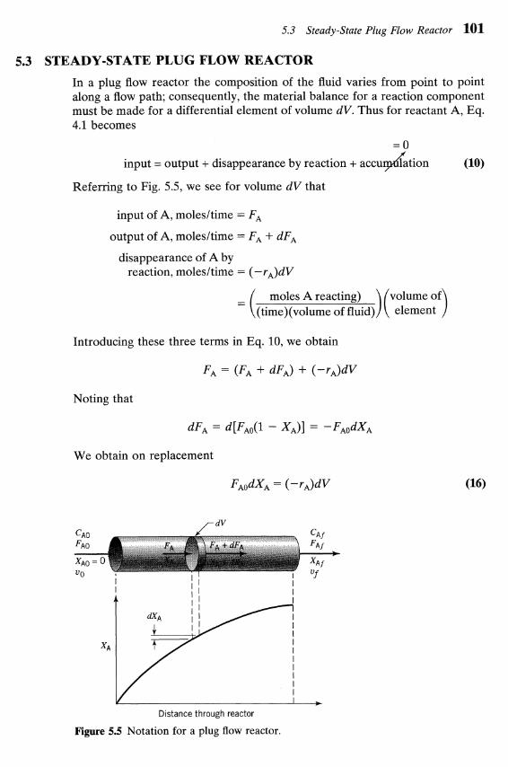
In a plug flow reactor the composition of the fluid varies from point to point along a flow path; consequently, the material balance for a reaction component must be made for a differential element of volume dV. Thus for reactant A, Eq. 4.1 becomes
= 0
input = output + disappearance by reaction + accuydation (10)
Referring to Fig. 5.5, we see for volume dV that
input of A, molesltime = FA
output of A, molesltime = FA + dFA
disappearance of A by reaction, molesltime = (-r,)dV
moles A reacting) = ((time)(volume of fluid)
Introducing these three terms in Eq. 10, we obtain
Noting that
We obtain on replacement
Distance through reactor
Figure 5.5 Notation for a plug flow reactor.
102 Chapter 5 Ideal Reactors for a Single Reaction
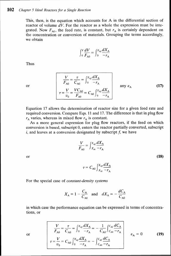
This, then, is the equation which accounts for A in the differential section of reactor of volume dV. For the reactor as a whole the expression must be inte- grated. Now FA,, the feed rate, is constant, but r, is certainly dependent on the concentration or conversion of materials. Grouping the terms accordingly, we obtain
Thus
Equation 17 allows the determination of reactor size for a given feed rate and required conversion. Compare Eqs. 11 and 17. The difference is that in plug flow rA varies, whereas in mixed flow rA is constant.
As a more general expression for plug flow reactors, if the feed on which conversion is based, subscript 0, enters the reactor partially converted, subscript i, and leaves at a conversion designated by subscript f, we have
For the special case of constant-density systems
X A = l - - ~ C A and dXA = - - C ~ o C ~ o
in which case the performance equation can be expressed in terms of concentra- tions, or

5.3 Steady-State Plug Flow Reactor 103
Figure 5.6 Graphical representation of the performance equations for plug flow reactors.
pzziq
These performance equations, Eqs. 17 to 19, can be written either in terms of concentrations or conversions. For systems of changing density it is more conve- nient to use conversions; however, there is no particular preference for constant density systems. Whatever its form, the performance equations interrelate the rate of reaction, the extent of reaction, the reactor volume, and the feed rate, and if any one of these quantities is unknown it can be found from the other three.
Figure 5.6 displays these performance equations and shows that the space- time needed for any particular duty can always be found by numerical or graphical integration. However, for certain simple kinetic forms analytic integration is possible-and convenient. To do this, insert the kinetic expression for r, in Eq. 17 and integrate. Some of the simpler integrated forms for plug flow are as follows: Zero-order homogeneous reaction, any constant E,
Constant-density systems only
First-order irreversible reaction, A + products, any constant &A,
k7=-(1+ ln (1 - x,) - 1 (21)
First-order reversible reaction, A * rR, CRdCAo = M , kinetics approximated or fitted by -r, = klCA - k2CR with an observed equilibrium conversion XAe, any constant &A,
Second-order irreversible reaction, A + B +products with equimolar feed or 2A +products, any constant E,,

104 Chapter 5 Ideal Reactors for a Single Reaction
Where the density is constant, put E , = 0 to obtain the simplified perfor- mance equation. By comparing the batch expressions of Chapter 3 with these plug flow expressions we find:
(1) For systems of constant density (constant-volume batch and constant-den- sity plug flow) the performance equations are identical, T for plug flow is equivalent to t for the batch reactor, and the equations can be used interchangeably.
(2) For systems of changing density there is no direct correspondence between the batch and the plug flow equations and the correct equation must be used for each particular situation. In this case the performance equations cannot be used interchangeably.
The following illustrative examples show how to use these expressions.
PLUG FLOW REACTOR PERFORMANCE
I A homogeneous gas reaction A -+3R has a reported rate at 215OC
-rA = 10-2C~2, [mollliter sec]
Find the space-time needed for 80% conversion of a 50% A-50% inert feed to a plug flow reactor operating at 215OC and 5 atm (CAo = 0.0625 mollliter).
Figure E5.4a
For this stoichiometry and with 50% inerts, two volumes of feed gas would give four volumes of completely converted product gas; thus
in which case the plug flow performance equation, Eq. 17, becomes
1 The integral can be evaluated in any one of three ways: graphically, numerically, or analytically. Let us illustrate these methods.

5.3 Steady-State Plug Flow Reactor 105
Table E5.4
Graphical Integration. First evaluate the function to be integrated at selected values (see Table E5.4) and plot this function (see Fig. E5.4b).
Average height = 1.7
Area 1.7(0.8) = 1.36
XA
Figure E5.4b
Counting squares or estimating by eye we find
0.8 1 + xA ' I 2 Area = lo (-) dXA = (1.70)(0.8) = - 1.36 -
Numerical Integration. Using Simpson's rule, applicable to an even number of uniformly spaced intervals on the XA axis, we find for the data of Table E5.4,
( 2 ) ' l 2 dXA = (average height)(total width)
l(1) + 4(1.227) + 2(1.528) + 4(2) + l(3) 12 I

106 Chapter 5 Ideal Reactors for a Single Reaction
Analytical Integration. From a table of integrals
0.8 1 + x* 0 -
dX*
= (arc sin XA -
The method of integration recommended depends on the situation. In this prob- lem probably the numerical method is the quickest and simplest and gives a good enough answer for most purposes.
So with the integral evaluated, Eq. (i) becomes
7 = (0.0625 m~l l l i t e r )~ '~ (1.33) = 33.2 sec
= moll"lliterl". sec)
PLUG FLOW REACTOR VOLUME
The homogeneous gas decomposition of phosphine
proceeds at 649OC with the first-order rate
What size of plug flow reactor operating at 649°C and 460 kPa can produce 80% conversion of a feed consisting of 40 mol of pure phosphine per hour?
Lv=?
Figure E5.5
I SOLUTION
Let A = pH3, R = P4, S = H,. Then the reaction becomes

5.3 Steady-State Plug Flow Reactor 107
with
I The volume of plug flow reactor is given by Eq. 21
Evaluating the individual terms in this expression gives
FA, = 40 mollhr
k = lOlhr
PAO 460 000 Pa = = (8.314 Pa. m31mol. K)(922 K)
= 60 mol/m3
hence the volume of reactor
= 148 liters
TEST OF A KINETIC EQUATION IN A PLUG FLOW REACTOR
We suspect that the gas reaction between A, B, and R is an elementary revers- ible reaction
and we plan to test this with experiments in an isothermal plug flow reactor.
(a) Develop the isothermal performance equation for these kinetics for a feed of A, B, R, and inerts.
(b) Show how to test this equation for an equimolar feed of A and B.

108 Chapter 5 Ideal Reactors for a Single Reaction
(a) Feed of A, B, R, and inerts. For this elementary reaction the rate is
At constant pressure, basing expansion and conversion on substance A,
Letting M = CBdCAo, M' = CRdCAO, we obtain
Hence, the design equation for plug flow, Eq. 17, becomes
In this expression accounts for the stoichiometry and for inerts present in the feed.
(b) Equimolar feed of A and B. For CAo = CBo, CRo = 0, and no inerts, we have M = 1, M' = 0, = -0.5; hence the expression for part a reduces to
(1 - 0.5XA)2 dXA j:f(xA)dxA (i) o klCAo(l - XA)' - kZXA(I - 0.5XA) this
Having V, v,, and XA data from a series of experiments, separately evaluate the left side and the right side of Eq. (i). For the right side, at various XA
t = V/uo
Figure E5.6

5.3 Steady-State Plug Flow Reactor 109
evaluate f (X,), then integrate graphically to give Sf (XA)dXA and then make the plot of Fig. E5.6. If the data fall on a reasonably straight line, then the suggested kinetic scheme can be said to be satisfactory in that it fits the data.
Holding Time and Space Time for Flow Reactors
We should be clearly aware of the distinction between these two measures of time, 2 and 7. They are defined as follows:
time needed to
mean residence time of flowing material ~ X A
0 ( -YA)(~ + EAXA)' [hrl (24)
in the reactor
For constant density systems (all liquids and constant density gases)
For changing density systems 7 # 7 and 2 # Vlu, in which case it becomes difficult to find how these terms are related.
As a simple illustration of the difference between 2 and 7, consider two cases of the steady-flow popcorn popper of Problem 4.7 which takes in 1 literlmin of raw corn and produces 28 literslmin of product popcorn.
Consider three cases, called X, Y, and Z, which are shown in Fig. 5.7. In the first case (case X) all the popping occurs at the back end of the reactor. In the
Case X Case Y Case Z
+ 28 literlmin 28 literlmin
1 literlmin 1 literlmin, 1 literlmin, of unpopped corn unpopped unpopped
Figure 5.7 For the same 7 value the i values differ in these three cases.
110 Chapter 5 Ideal Reactors for a Single Reaction
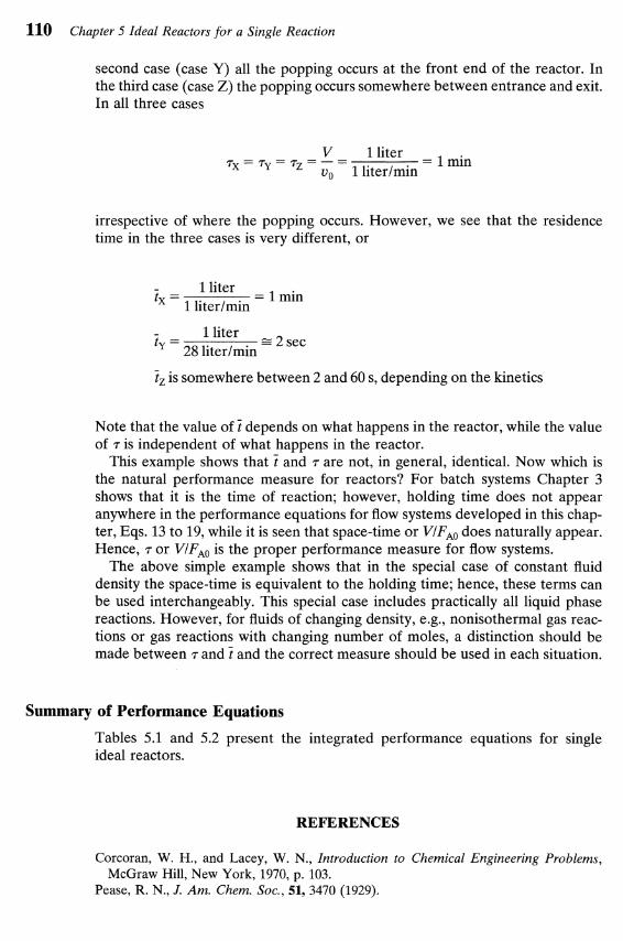
second case (case Y) all the popping occurs at the front end of the reactor. In the third case (case Z) the popping occurs somewhere between entrance and exit. In all three cases
V - 1 liter r x = r y = r z = - - = I min v, 1 literlmin
irrespective of where the popping occurs. However, we see that the residence time in the three cases is very different, or
1 liter t - - 1 literlmin
= 1 min
1 liter t - = 2 sec - 28 literlmin
7, is somewhere between 2 and 60 s, depending on the kinetics
Note that the value of t depends on what happens in the reactor, while the value of r is independent of what happens in the reactor.
This example shows that 7 and r are not, in general, identical. Now which is the natural performance measure for reactors? For batch systems Chapter 3 shows that it is the time of reaction; however, holding time does not appear anywhere in the performance equations for flow systems developed in this chap- ter, Eqs. 13 to 19, while it is seen that space-time or VIF,, does naturally appear. Hence, r or VIFAO is the proper performance measure for flow systems.
The above simple example shows that in the special case of constant fluid density the space-time is equivalent to the holding time; hence, these terms can be used interchangeably. This special case includes practically all liquid phase reactions. However, for fluids of changing density, e.g., nonisothermal gas reac- tions or gas reactions with changing number of moles, a distinction should be made between rand 7 and the correct measure should be used in each situation.
Summary of Performance Equations
Tables 5.1 and 5.2 present the integrated performance equations for single ideal reactors.
REFERENCES
Corcoran, W. H., and Lacey, W. N., Introduction to Chemical Engineering Problems, McGraw Hill, New York, 1970, p. 103.
Pease, R. N., J. Am. Chem. Soc., 51,3470 (1929).


Problems 113
PROBLEMS
5.1. Consider a gas-phase reaction 2A-R + 2s with unknown kinetics. If a space velocity of llmin is needed for 90% conversion of A in a plug flow reactor, find the corresponding space-time and mean residence time or holding time of fluid in the plug flow reactor.
5.2. In an isothermal batch reactor 70% of a liquid reactant is converted in 13 min. What space-time and space-velocity are needed to effect this conver- sion in a plug flow reactor and in a mixed flow reactor?
5.3. A stream of aqueous monomer A (1 mollliter, 4 literlmin) enters a 2-liter mixed flow reactor, is radiated therein, and polymerizes as follows:
+A t A t A A-R-S-T.. .
In the exit stream CA = 0.01 mollliter, and for a particular reaction product W, C, = 0.0002 mollliter. Find the rate of reaction of A and the rate of formation of W.
5.4. We plan to replace our present mixed flow reactor with one having double the volume. For the same aqueous feed (10 mol Alliter) and the same feed rate find the new conversion. The reaction kinetics are represented by
and present conversion is 70%.
5.5. An aqueous feed of A and B (400 literlmin, 100 mmol Alliter, 200 mmol Blliter) is to be converted to product in a plug flow reactor. The kinetics of the reaction is represented by
mol A + B + R , - rAZ200C C
A liter .min
Find the volume of reactor needed for 99.9% conversion of A to product.
5.6. A plug flow reactor (2 m3) processes an aqueous feed (100 literlmin) con- taining reactant A (CAo = 100 mmollliter). This reaction is reversible and represented by
First find the equilibrium conversion and then find the actual conversion of A in the reactor.

114 Chapter 5 Ideal Reactors for a Single Reaction
5.7. The off gas from a boiling water nuclear power reactor contains a whole variety of radioactive trash, one of the most troublesome being Xe-133 (half life = 5.2 days). This off gas flows continuously through a large holdup tank in which its mean residence time is 30 days, and where we can assume that the contents are well mixed. Find the fraction of activity removed in the tank.
5.8. A mixed flow reactor (2 m3) processes an aqueous feed (100 literlrnin) containing reactant A (C,, = 100 mmollliter). The reaction is reversible and represented by
mol A R, -7, = 0.04 CA - 0.01 CR
liter. min
What is the equilibrium conversion and the actual conversion in the reactor?
5.9. A specific enzyme acts as catalyst in the fermentation of reactant A. At a given enzyme concentration in the aqueous feed stream (25 literlmin) find the volume of plug flow reactor needed for 95% conversion of reactant A (C,, = 2 mollliter). The kinetics of the fermentation at this enzyme concentration is given by
enzyme 0.1 CA m01 A-R, -rA =
1 + 0.5 C, liter. min
5.10. A gaseous feed of pure A (2 mollliter, 100 mollmin) decomposes to give a variety of products in a plug flow reactor. The kinetics of the conversion is represented by
A -t 2.5 (products), -rA = (10 min-')C,
Find the expected conversion in a 22-liter reactor.
5.11. Enzyme E catalyses the fermentation of substrate A (the reactant) to product R. Find the size of mixed flow reactor needed for 95% conversion of reactant in a feed stream (25 literlmin) of reactant (2 mollliter) and enzyme. The kinetics of the fermentation at this enzyme concentration are given by
enzyme 0.1 cA m01 A-R, -?'A=
1 + 0.5 C, liter min
5.12. An aqueous feed of A and B (400 literlmin, 100 mmol Alliter, 200 mmol Blliter) is to be converted to product in a mixed flow reactor. The kinetics

Problems 115
of the reaction are represented by
mol A + B + R , -rA=200CACB liter min
Find the volume of reactor needed for 99.9% conversion of A to product.
5.13. At 650°C phosphine vapor decomposes as follows:
What size of plug flow reactor operating at 649°C and 11.4 atm is needed for 75% conversion of 10 mollhr of phosphine in a 213 phosphine-113 inert feed?
5.14. A stream of pure gaseous reactant A (CAo = 660 mmollliter) enters a plug flow reactor at a flow rate of FA, = 540 mmollmin and polymerizes there as follows
mmol 3A+R, -r,=54
liter min
How large a reactor is needed to lower the concentration of A in the exit stream to CAf = 330 mmollliter?
5.15. A gaseous feed of pure A (1 mollliter) enters a mixed flow reactor (2 liters) and reacts as follows:
mol 2A + R, -rA = 0.05 C i liter. sec
Find what feed rate (literlmin) will give an outlet concentration CA = 0.5 mollliter.
5.16. Gaseous reactant A decomposes as follows:
Find the conversion of A in a 50% A-50% inert feed (v, = 180 literlmin, CAo = 300 mmollliter) to a 1 m3 mixed flow reactor.
5.17. 1 literls of a 20% ozone-80% air mixture at 1.5 atm and 93°C passes through a plug flow reactor. Under these conditions ozone decomposes by homogeneous reaction
liter 20, +30,, -r,,,,, = kC~,on,, k = 0.05 -
mol . s
What size reactor is needed for 50% decomposition of ozone? This problem is a modification of a problem given by Corcoran and Lacey (1970).

116 Chapter 5 Ideal Reactors for a Single Reaction
5.18. An aqueous feed containing A (1 mollliter) enters a 2-liter plug flow reactor and reacts away (2A +R, - r , = 0.05 C2, mollliter s). Find the outlet con- centration of A for a feed rate of 0.5 literlmin.
5.19. Pure gaseous A at about 3 atm and 30°C (120 mmollliter) is fed into a 1- liter mixed flow reactor at various flow rates. There it decomposes, and the exit concentration of A is measured for each flow rate. From the following data find a rate equation to represent the kinetics of the decompo- sition of A. Assume that reactant A alone affects the rate.
v,, literlmin 0.06 0.48 1.5 8.1 A +3R C, , mmollliter 1 30 60 80 105
5.20. A mixed flow reactor is being used to determine the kinetics of a reaction whose stoichiometry is A +R. For this purpose various flow rates of an aqueous solution of 100 mmol Alliter are fed to a 1-liter reactor, and for each run the outlet concentration of A is measured. Find a rate equation to represent the following data. Also assume that reactant alone affects the rate.
v , literlmin 1 6 24 C,, mmollliter 4 20 50
5.21. We are planning to operate a batch reactor to convert A into R. This is a liquid reaction, the stoichiometry is A+R, and the rate of reaction is given in Table P5.21. How long must we react each batch for the concentra- tion to drop from C,, = 1.3 mollliter to CAf = 0.3 mollliter?
Table P5.21
C, , mollliter - rA, mollliter min
0.1 0.1 0.2 0.3 0.3 0.5 0.4 0.6 0.5 0.5 0.6 0.25 0.7 0.10 0.8 0.06 1.0 0.05 1.3 0.045 2.0 0.042
5.22. For the reaction of Problem 5.21, what size of plug flow reactor would be needed for 80% conversion of a feed stream of 1000 mol Alhr at CAo =
1.5 mollliter?
Problems 117
5.23. (a) For the reaction of Problem 5.21, what size of mixed flow reactor is needed for 75% conversion of a feed stream of 1000 mol Alhr at CAO = 1.2 mollliter?
(b) Repeat part (a) with the modification that the feed rate is doubled, thus 2000 mol Alhr at CAo = 1.2 mollliter are to be treated.
(c ) Repeat part (a) with the modification that CAo = 2.4 mollliter; however, 1000 mol Alhr are still to be treated down to CAf = 0.3 mollliter.
5.24. A high molecular weight hydrocarbon gas A is fed continuously to a heated high temperature mixed flow reactor where it thermally cracks (homoge- neous gas reaction) into lower molecular weight materials, collectively called R, by a stoichiometry approximated by A -5R. By changing the feed rate different extents of cracking are obtained as follows:
The internal void volume of the reactor is V = 0.1 liter, and at the tempera- ture of the reactor the feed concentration is CAo = 100 millimol/liter. Find a rate equation to represent the cracking reaction.
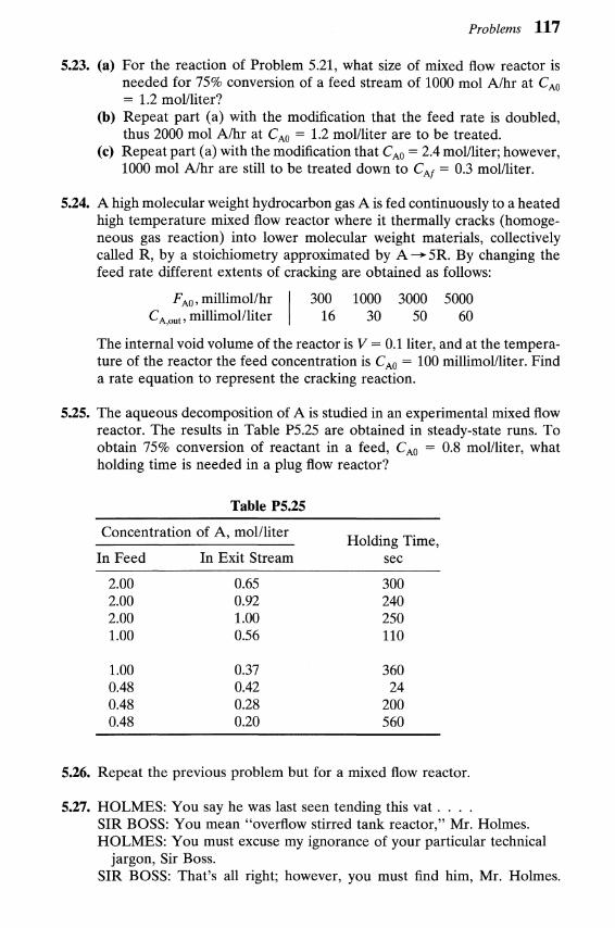
5.25. The aqueous decomposition of A is studied in an experimental mixed flow reactor. The results in Table P5.25 are obtained in steady-state runs. To obtain 75% conversion of reactant in a feed, CA, = 0.8 mollliter, what holding time is needed in a plug flow reactor?
Table P5.25
Concentration of A, mollliter Holding Time,
In Feed In Exit Stream sec
5.26. Repeat the previous problem but for a mixed flow reactor.
5.27. HOLMES: You say he was last seen tending this vat . . . . SIR BOSS: You mean "overflow stirred tank reactor," Mr. Holmes. HOLMES: You must excuse my ignorance of your particular technical
jargon, Sir Boss. SIR BOSS: That's all right; however, you must find him, Mr. Holmes.

118 Chapter 5 Ideal Reactors for a Single Reaction
Imbibit was a queer chap; always staring into the reactor, taking deep breaths, and licking his lips, but he was our very best operator. Why, since he left, our conversion of googliox has dropped from 80% to 75%.
HOLMES (tapping the side of the vat idly): By the way, what goes on in the vat?
SIR BOSS: Just an elementary second-order reaction, between ethanol and googliox, if you know what I mean. Of course, we maintain a large excess of alcohol, about 100 to 1 and . . . .
HOLMES (interrupting): Intriguing, we checked every possible lead in town and found not a single clue.
SIR BOSS (wiping away the tears): We'll give the old chap a raise-about twopence per week-if only he'll come back.
DR. WATSON: Pardon me, but may I ask a question? HOLMES: Why certainly, Watson. WATSON: What is the capacity of this vat, Sir Boss? SIR BOSS: A hundred Imperial gallons, and we always keep it filled to
the brim. That is why we call it an overflow reactor. You see we are running at full capacity-profitable operation you know.
HOLMES: Well, my dear Watson, we must admit that we're stumped, for without clues deductive powers are of no avail.
WATSON: Ahh, but there is where you are wrong, Holmes. (Then, turning to the manager): Imbibit was a largish fellow-say about 18 stone-was he not?
SIR BOSS: Why yes, how did you know? HOLMES (with awe): Amazing, my dear Watson! WATSON (modestly): Why it's quite elementary, Holmes. We have all the
clues necessary to deduce what happened to the happy fellow. But first of all, would someone fetch me some dill?
With Sherlock Holmes and Sir Boss impatiently waiting, Dr. Watson casually leaned against the vat, slowly and carefully filled his pipe, and- with the keen sense of the dramatic-lit it. There our story ends. (a) What momentous revelation was Dr. Watson planning to make, and
how did he arrive at this conclusion? (b) Why did he never make it?
5.28. The data in Table P5.28 have been obtained on the decomposition of gaseous reactant A in a constant volume batch reactor at 100°C. The
Table P5.28
t, sec PA, atm t , sec PA, atm
0 1.00 140 0.25 20 0.80 200 0.14 40 0.68 260 0.08 60 0.56 330 0.04 80 0.45 420 0.02
100 0.37
Problems 119
stoichiometry of the reaction is 2A -+ R + S. What size plug flow reactor (in liters) operating at 100°C and 1 atm can treat 100 mol Alhr in a feed consisting of 20% inerts to obtain 95% converson of A?
5.29. Repeat the previous problem for a mixed flow reactor.
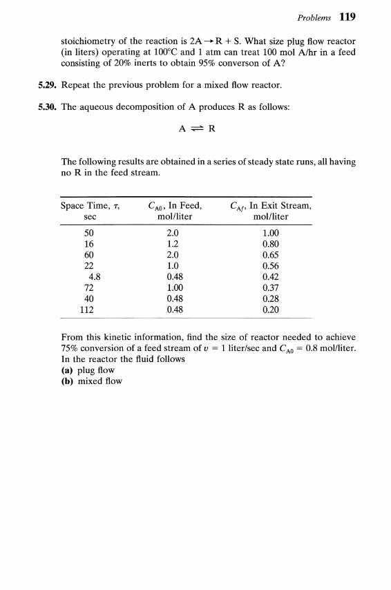
5.30. The aqueous decomposition of A produces R as follows:
The following results are obtained in a series of steady state runs, all having no R in the feed stream.
Space Time, r, C,, , In Feed, CAf, In Exit Stream, sec mollliter mollliter
From this kinetic information, find the size of reactor needed to achieve 75% conversion of a feed stream of v = 1 literlsec and C,, = 0.8 mollliter. In the reactor the fluid follows (a) plug flow (b) mixed flow